Patchmaster. Elektronik. The Pulse generator. February 2013
|
|
|
- Karin Dorsey
- 5 years ago
- Views:
Transcription

1 Patchmaster The Pulse generator Elektronik

2 Telly Galiatsatos, BS 1987: Graduated at Queens College, NY Computer Science : Instrutech Corporation IT Engineering Support Software Engineer, Sales & Support HEKA Product Specialist General Manager Since 2007: HEKA Instruments Inc, NY, USA General Manager
3 3 Overview Understanding the various controls Acquisition modes Example sequences
 Max Stim points per")
4 4 Configuration settings Memory allocation: Max Sample points per trace Max Stim traces (channels) Max Stim points per trace
 Max Stim points")

5 5 Configuration settings Memory allocation: Max Sample points per trace Max Stim traces (channels) Max Stim points per trace Auto Filter automatically sets filter based on filter factor and sample interval VC and CC stimulus scaling factors


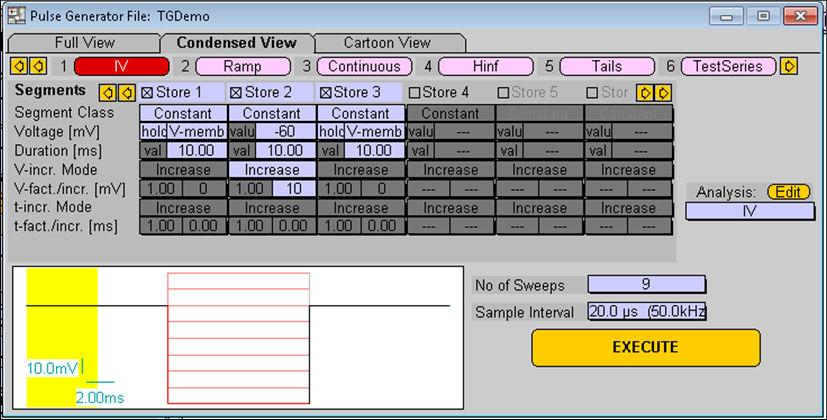
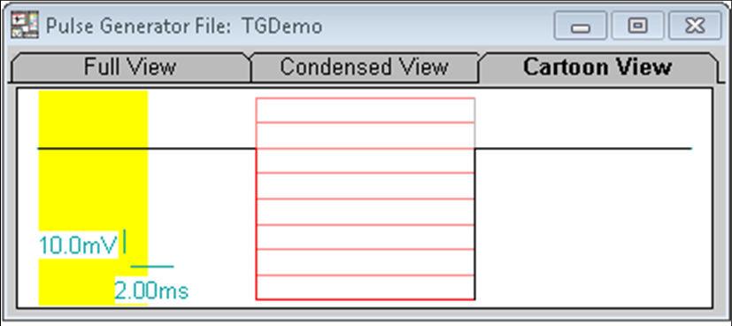
6 6 Various views Condensed Full Cartoon
7 7 Terminology PGF Pulse Generator file file that holds preprogrammed acquisition patterns Sequence Pool a collection of stimulation patterns Series A family of stimulation pulses and /or controls Sweep a single acquisition in a series File template external stimulus file PGF-parameters user variables
8 8 Sequence pool List of predefined sequences, each defined by a unique name Unlimited number of sequences per PGF file Commands for manipulating the sequences
9 9 Acquisition Modes Interactive mode: Processing and /or external controls are executed in-between sweeps Short sweep intervals will execute as fast as possible but are ultimately affected by active system tasks Longer sweep intervals will execute with accurate timing
10 10 Interactive Mode interval = 0
11 11 Interactive mode interval = 1 sec
12 12 Gap Free Mode Optimized DAQ control for gap free acquisition / stimulation Sweeps are executed without any gaps but.. all processing other than on-line analysis is disabled Real-time feedback is no longer available

13 13 Gap Free
14 14 Changing values Click and drag hold down right mouse button and drag up / down to change value Double click and enter double click on item, enter value via the keyboard in either scientific or engineering format: Tera: T / E12 Giga: G / E9 Mega: M / E6 Kilo: k or E3 - Milli: m / E-3 Micro: u / E-6 nano: n / E-9 - Pico: p / E-12 femto: f / E-15

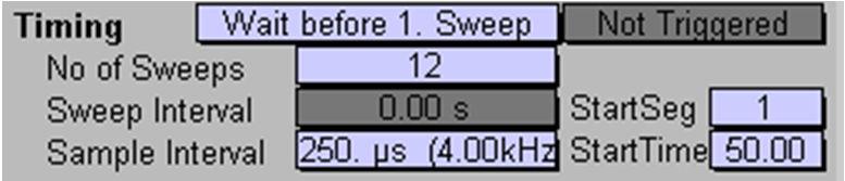
15 15 Timing Number of sweeps in a series The sweep interval: delay + sweep length Sample interval: sampling frequency of DAQ Delay the display and storing of acquired data with StartSeg and StartTime These timing parameters are common across all Input / output channels

16 16 Timing - Delay

17 17 Triggered Acquisition Initiate acquisition from an external trigger Trigger modes: Series single trigger start series Main only external trigger per sweep Main + Leaks external trigger per sweep and for each leak pulse
18 18 Input & Output channels Output channels - up to 16 D/A - Digital Word - Digital bit Input channels - up to 32 A/D Virtual - Digital Word - Digital bit Special Function: Chirp - Lock In - Imaging

19 19 D/A Output channels Scaling: Stimulus Scaling factor Output signal is relative to V- membrane Scaled by a specified factor Output values can be loaded from a file Scaled based on active extensions: LockIn, Imaging, Spectroscopy or Photometry
20 20 Digital (TTL) Output channels Digital Word: output a 16 bit word Change multiple digital outputs simultaneously Best way to control perfusion systems Digital Bit: single digital channel Control single TTL lines Easier to configure
21 21 Common settings for Input Channels: Link to a particular parent channel Link to related output channel Original current channel, e.g. LockIn Perform data compression Enable / disable storing to disk Specify segment used to calculate auto-zero If A/D input and Leak Pulses are enabled: store none, leak average or each leak pulse with data Virtual channels: Create an input by mathematical computations of other traces and inputs

22 22 Segments Arbitrary number of segments, each defined by: Class Store / No-store Voltage / Current Duration Increment mode Increment factors
23 23 Segment Class Standard segments: Constant constant amplitude Ramp from previous segments amplitude to current segments amplitude Continuous identifier for continuous acquisition not affected by stimulus buffer size Can only be last segment in pulse pattern Fixed amplitude
24 24 Segment Class Special segments have separate wave parameter definitions Sine Sine characteristics Square rectangular characteristics Chirp increasing sine wave frequency

25 25 Segment editing commands Insert Insert new segment at this location Duplicate copy this segment and insert next to this one Delete delete this segment Duplicate - duplicate x number of segments n times from this one Delete - delete x number of segments from this one


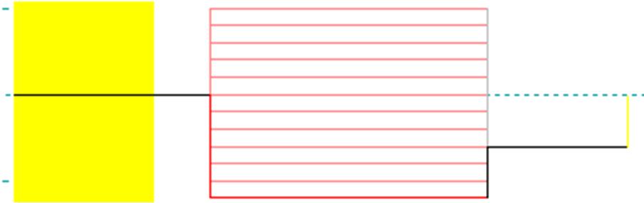
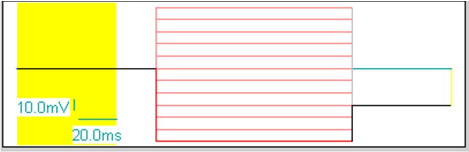
26 26 Template Preview Graphical representation of pulse patterns Display delay settings Specify Holding potential for accurate representation

27 27 P/N Leak Subtraction Arbitrary number of P/N pulses Leak pulses execute before or after main pulse Specify Lead Holding, Leak Size, or alternating polarity pulses Raw and leak corrected data can be stored


28 28 PGF Parameters Variables allow sequences to be changed without editing or creating new ones
29 29 Acquisition to Analysis
PulseCounter Neutron & Gamma Spectrometry Software Manual
 PulseCounter Neutron & Gamma Spectrometry Software Manual MAXIMUS ENERGY CORPORATION Written by Dr. Max I. Fomitchev-Zamilov Web: maximus.energy TABLE OF CONTENTS 0. GENERAL INFORMATION 1. DEFAULT SCREEN
Tutorial FITMASTER Tutorial
 Tutorial 2.20 FITMASTER Tutorial HEKA Elektronik Phone +49 (0) 6325 / 95 53-0 Dr. Schulze GmbH Fax +49 (0) 6325 / 95 53-50 Wiesenstrasse 71 Web Site www.heka.com D-67466 Lambrecht/Pfalz Email sales@heka.com
Using the HDCV Data Acquisition Program
 Using the HDCV Data Acquisition Program This manual describes HDCV.exe, the data acquisition portion of the HDCV (High Definition Cyclic Voltammetry) program suite from the University of North Carolina
Torsional vibration analysis in ArtemiS SUITE 1
 02/18 in ArtemiS SUITE 1 Introduction 1 Revolution speed information as a separate analog channel 1 Revolution speed information as a digital pulse channel 2 Proceeding and general notes 3 Application
Pre-processing of revolution speed data in ArtemiS SUITE 1
 03/18 in ArtemiS SUITE 1 Introduction 1 TTL logic 2 Sources of error in pulse data acquisition 3 Processing of trigger signals 5 Revolution speed acquisition with complex pulse patterns 7 Introduction
MTL Software. Overview
 MTL Software Overview MTL Windows Control software requires a 2350 controller and together - offer a highly integrated solution to the needs of mechanical tensile, compression and fatigue testing. MTL
ME EN 363 ELEMENTARY INSTRUMENTATION Lab: Basic Lab Instruments and Data Acquisition
 ME EN 363 ELEMENTARY INSTRUMENTATION Lab: Basic Lab Instruments and Data Acquisition INTRODUCTION Many sensors produce continuous voltage signals. In this lab, you will learn about some common methods
Analyzing and Saving a Signal
 Analyzing and Saving a Signal Approximate Time You can complete this exercise in approximately 45 minutes. Background LabVIEW includes a set of Express VIs that help you analyze signals. This chapter teaches
DDA-UG-E Rev E ISSUED: December 1999 ²
 7LPHEDVH0RGHVDQG6HWXS 7LPHEDVH6DPSOLQJ0RGHV Depending on the timebase, you may choose from three sampling modes: Single-Shot, RIS (Random Interleaved Sampling), or Roll mode. Furthermore, for timebases
PicoScope 6407 Digitizer
 YE AR PicoScope 6407 Digitizer HIGH PERFORMANCE USB DIGITIZER Programmable and Powerful 1 GHz bandwidth 1 GS buffer size 5 GS/s real-time sampling Advanced digital triggers Built-in function generator
PRELIMINARY INFORMATION. Professional Signal Generation and Monitoring Options for RIFEforLIFE Research Equipment
 Integrated Component Options Professional Signal Generation and Monitoring Options for RIFEforLIFE Research Equipment PRELIMINARY INFORMATION SquareGENpro is the latest and most versatile of the frequency
The most sensitive microelectrode array system for in vitro extracellular electrophysiology. Mobius Tutorial AMPLIFIER TYPE MED-A64MD1/MED-A64HE1
 The most sensitive microelectrode array system for in vitro extracellular electrophysiology Mobius Tutorial AMPLIFIER TYPE MED-A64MD1/MED-A64HE1 Information in this document is subject to change without
Advanced Synchronization Techniques for Data Acquisition
 Application Note 128 Advanced Synchronization Techniques for Data Acquisition Introduction Brad Turpin Many of today s instrumentation solutions require sophisticated timing of a variety of I/O functions
Agilent Parallel Bit Error Ratio Tester. System Setup Examples
 Agilent 81250 Parallel Bit Error Ratio Tester System Setup Examples S1 Important Notice This document contains propriety information that is protected by copyright. All rights are reserved. Neither the
SigPlay User s Guide
 SigPlay User s Guide . . SigPlay32 User's Guide? Version 3.4 Copyright? 2001 TDT. All rights reserved. No part of this manual may be reproduced or transmitted in any form or by any means, electronic or
PicoScope 6 Training Manual
 PicoScope 6 Training Manual DO226 PicoScope 6 Training Manual r2.docx Copyright 2014 Pico Technology CONTENTS 1 Quick guide to PicoScope 6... 1 1.1 The PicoScope way... 1 1.2 Signal view... 2 1.3 Timebase...
PicoScope 6407 Digitizer
 YE AR HIGH PERFORMANCE USB DIGITIZER Programmable and Powerful 1 GHz bandwidth 1 GS buffer size 5 GS/s real-time sampling Advanced digital triggers Built-in function generator USB-connected Signals Analysis
A low noise multi electrode array system for in vitro electrophysiology. Mobius Tutorial AMPLIFIER TYPE SU-MED640
 A low noise multi electrode array system for in vitro electrophysiology Mobius Tutorial AMPLIFIER TYPE SU-MED640 Information in this document is subject to change without notice.no part of this document
ISCEV SINGLE CHANNEL ERG PROTOCOL DESIGN
 ISCEV SINGLE CHANNEL ERG PROTOCOL DESIGN This spreadsheet has been created to help design a protocol before actually entering the parameters into the Espion software. It details all the protocol parameters
Electrical and Electronic Laboratory Faculty of Engineering Chulalongkorn University. Cathode-Ray Oscilloscope (CRO)
") 2141274 Electrical and Electronic Laboratory Faculty of Engineering Chulalongkorn University Cathode-Ray Oscilloscope (CRO) Objectives You will be able to use an oscilloscope to measure voltage, frequency
2141274 Electrical and Electronic Laboratory Faculty of Engineering Chulalongkorn University Cathode-Ray Oscilloscope (CRO) Objectives You will be able to use an oscilloscope to measure voltage, frequency
Application Note AN-708 Vibration Measurements with the Vibration Synchronization Module
 Application Note AN-708 Vibration Measurements with the Vibration Synchronization Module Introduction The vibration module allows complete analysis of cyclical events using low-speed cameras. This is accomplished
THE BERGEN EEG-fMRI TOOLBOX. Gradient fmri Artifatcs Remover Plugin for EEGLAB 1- INTRODUCTION
 THE BERGEN EEG-fMRI TOOLBOX Gradient fmri Artifatcs Remover Plugin for EEGLAB 1- INTRODUCTION This EEG toolbox is developed by researchers from the Bergen fmri Group (Department of Biological and Medical
NanoGiant Oscilloscope/Function-Generator Program. Getting Started
 Getting Started Page 1 of 17 NanoGiant Oscilloscope/Function-Generator Program Getting Started This NanoGiant Oscilloscope program gives you a small impression of the capabilities of the NanoGiant multi-purpose
Revision History. SDG2000X Firmware Revision History and Update Instructions
 Revision History Date Version Revision 2/28/2018 2.01.01.23R8 Optimized calibration and PV process on the production line. 8/29/2017 2.01.01.23R7 1. Supported system recovery from U-disk. 2. Fixed a bug
TL-2900 AMMONIA & NITRATE ANALYZER DUAL CHANNEL
 TL-2900 AMMONIA & NITRATE ANALYZER DUAL CHANNEL DATA ACQUISITION SYSTEM V.15.4 INSTRUCTION MANUAL Timberline Instruments, LLC 1880 S. Flatiron Ct., Unit I Boulder, Colorado 80301 Ph: (303) 440-8779 Fx:
System Requirements SA0314 Spectrum analyzer:
 System Requirements SA0314 Spectrum analyzer: System requirements Windows XP, 7, Vista or 8: 1 GHz or faster 32-bit or 64-bit processor 1 GB RAM 10 MB hard disk space \ 1. Getting Started Insert DVD into
Linrad On-Screen Controls K1JT
 Linrad On-Screen Controls K1JT Main (Startup) Menu A = Weak signal CW B = Normal CW C = Meteor scatter CW D = SSB E = FM F = AM G = QRSS CW H = TX test I = Soundcard test mode J = Analog hardware tune
Auxiliary states devices
 22 Auxiliary states devices When sampling using multiple frame states, Signal can control external devices such as stimulators in addition to switching the 1401 outputs. This is achieved by using auxiliary
Logic Analyzer Auto Run / Stop Channels / trigger / Measuring Tools Axis control panel Status Display
 Logic Analyzer The graphical user interface of the Logic Analyzer fits well into the overall design of the Red Pitaya applications providing the same operating concept. The Logic Analyzer user interface
User Guide & Reference Manual
 TSA3300 TELEPHONE SIGNAL ANALYZER User Guide & Reference Manual Release 2.1 June 2000 Copyright 2000 by Advent Instruments Inc. TSA3300 TELEPHONE SIGNAL ANALYZER ii Overview SECTION 1 INSTALLATION & SETUP
D-901 PC SOFTWARE Version 3
 INSTRUCTION MANUAL D-901 PC SOFTWARE Version 3 Please follow the instructions in this manual to obtain the optimum results from this unit. We also recommend that you keep this manual handy for future reference.
PS User Guide Series Seismic-Data Display
 PS User Guide Series 2015 Seismic-Data Display Prepared By Choon B. Park, Ph.D. January 2015 Table of Contents Page 1. File 2 2. Data 2 2.1 Resample 3 3. Edit 4 3.1 Export Data 4 3.2 Cut/Append Records
Oscilloscopes, logic analyzers ScopeLogicDAQ
 Oscilloscopes, logic analyzers ScopeLogicDAQ ScopeLogicDAQ 2.0 is a comprehensive measurement system used for data acquisition. The device includes a twochannel digital oscilloscope and a logic analyser
1 Synchronising Xsens with the Delsys Trigno EMG System
 1 Synchronising Xsens with the Delsys Trigno EMG System The steps described below show how to configure Xsens systems to control start and stop of a recording of the Delsys Trigno EMG system, and how to
What s New in Raven May 2006 This document briefly summarizes the new features that have been added to Raven since the release of Raven
 What s New in Raven 1.3 16 May 2006 This document briefly summarizes the new features that have been added to Raven since the release of Raven 1.2.1. Extensible multi-channel audio input device support
Effective Test Procedures for Installing and Maintaining RF Transmitter Sites
 Product: Hand Held Spectrum Analyzer R&S FSH3 Effective Test Procedures for Installing and Maintaining RF Transmitter Sites This application note describes an effective method for generating test setups,
Figure 30.1a Timing diagram of the divide by 60 minutes/seconds counter
 Digital Clock The timing diagram figure 30.1a shows the time interval t 6 to t 11 and t 19 to t 21. At time interval t 9 the units counter counts to 1001 (9) which is the terminal count of the 74x160 decade
Please feel free to download the Demo application software from analogarts.com to help you follow this seminar.
 Hello, welcome to Analog Arts spectrum analyzer tutorial. Please feel free to download the Demo application software from analogarts.com to help you follow this seminar. For this presentation, we use a
2 MHz Lock-In Amplifier
 2 MHz Lock-In Amplifier SR865 2 MHz dual phase lock-in amplifier SR865 2 MHz Lock-In Amplifier 1 mhz to 2 MHz frequency range Dual reference mode Low-noise current and voltage inputs Touchscreen data display
HST Neural Coding and Perception of Sound. Spring Cochlear Nucleus Unit Classification from Spike Trains. M.
 Harvard-MIT Division of Health Sciences and Technology HST.723: Neural Coding and Perception of Sound Instructor: Bertrand Delgutte HST.723 - Neural Coding and Perception of Sound Spring 2004 Cochlear
Tiptop audio z-dsp.
 Tiptop audio z-dsp www.tiptopaudio.com Introduction Welcome to the world of digital signal processing! The Z-DSP is a modular synthesizer component that can process and generate audio using a dedicated
EASY-MCS. Multichannel Scaler. Profiling Counting Rates up to 150 MHz with 15 ppm Time Resolution.
 Multichannel Scaler Profiling Counting Rates up to 150 MHz with 15 ppm Time Resolution. The ideal solution for: Time-resolved single-photon counting Phosphorescence lifetime spectrometry Atmospheric and
Transmitter Interface Program
 Transmitter Interface Program Operational Manual Version 3.0.4 1 Overview The transmitter interface software allows you to adjust configuration settings of your Max solid state transmitters. The following
ECE438 - Laboratory 4: Sampling and Reconstruction of Continuous-Time Signals
 Purdue University: ECE438 - Digital Signal Processing with Applications 1 ECE438 - Laboratory 4: Sampling and Reconstruction of Continuous-Time Signals October 6, 2010 1 Introduction It is often desired
The high-end network analyzers from Rohde & Schwarz now include an option for pulse profile measurements plus, the new R&S ZVA 40 covers the
 GENERAL PURPOSE 44 448 The high-end network analyzers from Rohde & Schwarz now include an option for pulse profile measurements plus, the new R&S ZVA 4 covers the frequency range up to 4 GHz. News from
WaveView. and. WaveCal
 WaveView and WaveCal WaveView Introduction 1 Software Startup & Sample Acquisition 3 Startup WaveView 3 Configure Channels 5 Configure Acquisition 6 Collect and View Data 6 Store Data [and View File Data]
Quick Reference Manual
 Quick Reference Manual V1.0 1 Contents 1.0 PRODUCT INTRODUCTION...3 2.0 SYSTEM REQUIREMENTS...5 3.0 INSTALLING PDF-D FLEXRAY PROTOCOL ANALYSIS SOFTWARE...5 4.0 CONNECTING TO AN OSCILLOSCOPE...6 5.0 CONFIGURE
The BAT WAVE ANALYZER project
 The BAT WAVE ANALYZER project Conditions of Use The Bat Wave Analyzer program is free for personal use and can be redistributed provided it is not changed in any way, and no fee is requested. The Bat Wave
This guide gives a brief description of the ims4 functions, how to use this GUI and concludes with a number of examples.
 Quick Start Guide: Isomet ims Studio Isomet ims Studio v1.40 is the first release of the Windows graphic user interface for the ims4- series of 4 channel synthezisers, build level rev A and rev B. This
HBI Database. Version 2 (User Manual)
") HBI Database Version 2 (User Manual) St-Petersburg, Russia 2007 2 1. INTRODUCTION...3 2. RECORDING CONDITIONS...6 2.1. EYE OPENED AND EYE CLOSED CONDITION....6 2.2. VISUAL CONTINUOUS PERFORMANCE TASK...6
HBI Database Version 2 (User Manual) St-Petersburg, Russia 2007 2 1. INTRODUCTION...3 2. RECORDING CONDITIONS...6 2.1. EYE OPENED AND EYE CLOSED CONDITION....6 2.2. VISUAL CONTINUOUS PERFORMANCE TASK...6
Fig. 1. The Front Panel (Graphical User Interface)
") ME 4710 Motion and Control Data Acquisition Software for Step Excitation Introduction o These notes describe LabVIEW software that can be used for data acquisition. The overall software characteristics
ME 4710 Motion and Control Data Acquisition Software for Step Excitation Introduction o These notes describe LabVIEW software that can be used for data acquisition. The overall software characteristics
WAVES Cobalt Saphira. User Guide
 WAVES Cobalt Saphira TABLE OF CONTENTS Chapter 1 Introduction... 3 1.1 Welcome... 3 1.2 Product Overview... 3 1.3 Components... 5 Chapter 2 Quick Start Guide... 6 Chapter 3 Interface and Controls... 7
Agilent PN Time-Capture Capabilities of the Agilent Series Vector Signal Analyzers Product Note
 Agilent PN 89400-10 Time-Capture Capabilities of the Agilent 89400 Series Vector Signal Analyzers Product Note Figure 1. Simplified block diagram showing basic signal flow in the Agilent 89400 Series VSAs
EDL8 Race Dash Manual Engine Management Systems
 Engine Management Systems EDL8 Race Dash Manual Engine Management Systems Page 1 EDL8 Race Dash Page 2 EMS Computers Pty Ltd Unit 9 / 171 Power St Glendenning NSW, 2761 Australia Phone.: +612 9675 1414
The Measurement Tools and What They Do
 2 The Measurement Tools The Measurement Tools and What They Do JITTERWIZARD The JitterWizard is a unique capability of the JitterPro package that performs the requisite scope setup chores while simplifying
4 MHz Lock-In Amplifier
 4 MHz Lock-In Amplifier SR865A 4 MHz dual phase lock-in amplifier SR865A 4 MHz Lock-In Amplifier 1 mhz to 4 MHz frequency range Low-noise current and voltage inputs Touchscreen data display - large numeric
16 Stage Bi-Directional LED Sequencer
 16 Stage Bi-Directional LED Sequencer The bi-directional sequencer uses a 4 bit binary up/down counter (CD4516) and two "1 of 8 line decoders" (74HC138 or 74HCT138) to generate the popular "Night Rider"
SEM- EDS Instruction Manual
 SEM- EDS Instruction Manual Double-click on the Spirit icon ( ) on the desktop to start the software program. I. X-ray Functions Access the basic X-ray acquisition, display and analysis functions through
SpikePac User s Guide
 SpikePac User s Guide Updated: 7/22/2014 SpikePac User's Guide Copyright 2008-2014 Tucker-Davis Technologies, Inc. (TDT). All rights reserved. No part of this manual may be reproduced or transmitted in
Pseudorandom Stimuli Following Stimulus Presentation
 BIOPAC Systems, Inc. 42 Aero Camino Goleta, CA 93117 Ph (805) 685-0066 Fax (805) 685-0067 www.biopac.com info@biopac.com Application Note AS-222 05.06.05 Pseudorandom Stimuli Following Stimulus Presentation
EAN-Performance and Latency
 EAN-Performance and Latency PN: EAN-Performance-and-Latency 6/4/2018 SightLine Applications, Inc. Contact: Web: sightlineapplications.com Sales: sales@sightlineapplications.com Support: support@sightlineapplications.com
LeCroy Digital Oscilloscopes
 LeCroy Digital Oscilloscopes Get the Complete Picture Quick Reference Guide QUICKSTART TO SIGNAL VIEWING Quickly display a signal View with Analog Persistence 1. Connect your signal. When you use a probe,
Lab experience 1: Introduction to LabView
 Lab experience 1: Introduction to LabView LabView is software for the real-time acquisition, processing and visualization of measured data. A LabView program is called a Virtual Instrument (VI) because
Operating Instructions
 Operating Instructions HAEFELY TEST AG KIT Measurement Software Version 1.0 KIT / En Date Version Responsable Changes / Reasons February 2015 1.0 Initial version WARNING Introduction i Before operating
TcCalc. Drastic Time Code Calculator
 TcCalc Drastic Time Code Calculator Table of Contents Overview...3 Features...3 Supported Platforms...3 Reference...4 Main Interface...4 Keyboard Shortcuts...6 User Guide...7 Calculate Between Video Standards...7
Manual Supplement. This supplement contains information necessary to ensure the accuracy of the above manual.
 Manual Title: 9500B Users Supplement Issue: 2 Part Number: 1625019 Issue Date: 9/06 Print Date: October 2005 Page Count: 6 Version 11 This supplement contains information necessary to ensure the accuracy
CDHD Servo Drive. Technical Training Manual. Manual Revision: 2.0 Firmware Version: 1.3.x Software Version: 1.3.x.x
 CDHD Servo Drive Technical Training Manual Manual Revision: 2.0 Firmware Version: 1.3.x Software Version: 1.3.x.x CDHD Introduction Revision History Document Revision Date Remarks 1.0 June 2012 Initial
Virtual instruments and introduction to LabView
 Introduction Virtual instruments and introduction to LabView (BME-MIT, updated: 26/08/2014 Tamás Krébesz krebesz@mit.bme.hu) The purpose of the measurement is to present and apply the concept of virtual
RICHLAND COLLEGE School of Engineering Business & Technology Rev. 0 W. Slonecker Rev. 1 (8/26/2012) J. Bradbury
 J. Bradbury") RICHLAND COLLEGE School of Engineering Business & Technology Rev. 0 W. Slonecker Rev. 1 (8/26/2012) J. Bradbury INTC 1307 Instrumentation Test Equipment Teaching Unit 8 Oscilloscopes Unit 8: Oscilloscopes
RICHLAND COLLEGE School of Engineering Business & Technology Rev. 0 W. Slonecker Rev. 1 (8/26/2012) J. Bradbury INTC 1307 Instrumentation Test Equipment Teaching Unit 8 Oscilloscopes Unit 8: Oscilloscopes
!Ill ~ 168. Model490 Dual Input, Dual Trace Automatic Peak Power Meter
 Model490 Dual Input, Dual Trace Automatic Peak Power Meter No other power meter can offer you these features: Help Mode: A Help Mode feature has been added to the Model 490 Automatic Peak Power Meter.
PYROPTIX TM IMAGE PROCESSING SOFTWARE
 Innovative Technologies for Maximum Efficiency PYROPTIX TM IMAGE PROCESSING SOFTWARE V1.0 SOFTWARE GUIDE 2017 Enertechnix Inc. PyrOptix Image Processing Software v1.0 Section Index 1. Software Overview...
SC26 Magnetic Field Cancelling System
 SPICER CONSULTING SYSTEM SC26 SC26 Magnetic Field Cancelling System Makes the ambient magnetic field OK for electron beam tools in 300 mm wafer fabs Real time, wideband cancelling from DC to > 9 khz fields
Oscilloscope Guide Tektronix TDS3034B & TDS3052B
 Tektronix TDS3034B & TDS3052B Version 2008-Jan-1 Dept. of Electrical & Computer Engineering Portland State University Copyright 2008 Portland State University 1 Basic Information This guide provides basic
User Manual. English. Sequencer Control Option BE3200. I en HBM: public
 User Manual English Sequencer Control Option BE3200 I2702-1.2 en HBM: public Document version 1.2 - July 2016 References made to the Perception software are for version 7.00 or higher For HBM's Terms and
Brain-Computer Interface (BCI)
") Brain-Computer Interface (BCI) Christoph Guger, Günter Edlinger, g.tec Guger Technologies OEG Herbersteinstr. 60, 8020 Graz, Austria, guger@gtec.at This tutorial shows HOW-TO find and extract proper signal
Brain-Computer Interface (BCI) Christoph Guger, Günter Edlinger, g.tec Guger Technologies OEG Herbersteinstr. 60, 8020 Graz, Austria, guger@gtec.at This tutorial shows HOW-TO find and extract proper signal
invr User s Guide Rev 1.4 (Aug. 2004)
") Contents Contents... 2 1. Program Installation... 4 2. Overview... 4 3. Top Level Menu... 4 3.1 Display Window... 9 3.1.1 Channel Status Indicator Area... 9 3.1.2. Quick Control Menu... 10 4. Detailed
Contents Contents... 2 1. Program Installation... 4 2. Overview... 4 3. Top Level Menu... 4 3.1 Display Window... 9 3.1.1 Channel Status Indicator Area... 9 3.1.2. Quick Control Menu... 10 4. Detailed
NOTICE: This document is for use only at UNSW. No copies can be made of this document without the permission of the authors.
 Brüel & Kjær Pulse Primer University of New South Wales School of Mechanical and Manufacturing Engineering September 2005 Prepared by Michael Skeen and Geoff Lucas NOTICE: This document is for use only
A Matlab toolbox for. Characterisation Of Recorded Underwater Sound (CHORUS) USER S GUIDE
 USER S GUIDE") Centre for Marine Science and Technology A Matlab toolbox for Characterisation Of Recorded Underwater Sound (CHORUS) USER S GUIDE Version 5.0b Prepared for: Centre for Marine Science and Technology Prepared
Centre for Marine Science and Technology A Matlab toolbox for Characterisation Of Recorded Underwater Sound (CHORUS) USER S GUIDE Version 5.0b Prepared for: Centre for Marine Science and Technology Prepared
Contents. 1. System Description 3. Overview 3 Part Names 3 Operating Conditions 7 Start-up Procedure 7. 2.
 Rigel 1550 Terahertz Spectrometer User Manual Contents info@tetechs.com 1. System Description 3 Overview 3 Part Names 3 Operating Conditions 7 Start-up Procedure 7 2. Safety 9 Laser Safety 9 Electrical
Using different reference quantities in ArtemiS SUITE
 06/17 in ArtemiS SUITE ArtemiS SUITE allows you to perform sound analyses versus a number of different reference quantities. Many analyses are calculated and displayed versus time, such as Level vs. Time,
PicoScope 9300 Series migration guide
 sampling oscilloscopes since 2009 The 9300 Series is a leading-edge product family resulting from a long program of product development. From late 2017, in the process of adding new 15 GHz and 25 GHz models,
Import and quantification of a micro titer plate image
 BioNumerics Tutorial: Import and quantification of a micro titer plate image 1 Aims BioNumerics can import character type data from TIFF images. This happens by quantification of the color intensity and/or
DT9834 Series High-Performance Multifunction USB Data Acquisition Modules
 DT9834 Series High-Performance Multifunction USB Data Acquisition Modules DT9834 Series High Performance, Multifunction USB DAQ Key Features: Simultaneous subsystem operation on up to 32 analog input channels,
Technology Control Technology
 L e a v i n g C e r t i f i c a t e Technology Control Technology P I C A X E 1 8 X Prog. 1.SOUND Output Prog. 3 OUTPUT & WAIT Prog. 6 LOOP Prog. 7...Seven Segment Display Prog. 8...Single Traffic Light
Reference. TDS7000 Series Digital Phosphor Oscilloscopes
 Reference TDS7000 Series Digital Phosphor Oscilloscopes 07-070-00 0707000 To Use the Front Panel You can use the dedicated, front-panel knobs and buttons to do the most common operations. Turn INTENSITY
NI-DAQmx Device Considerations
 NI-DAQmx Device Considerations January 2008, 370738M-01 This help file contains information specific to analog output (AO) Series devices, C Series, B Series, E Series devices, digital I/O (DIO) devices,
External Hardware Trigger Settings for RICOH Stereo Cameras
 External Hardware Trigger Settings for RICOH Stereo Cameras User s Guide RICOH Industrial Solutions Inc. 1/10 Contents 1. FUNCTIONAL OVERVIEW... 3 [Timing Diagram]... 3 2. POWER CONNECTOR... 4 [Connector
Digital Lock-In Amplifiers SR850 DSP lock-in amplifier with graphical display
 Digital Lock-In Amplifiers SR850 DSP lock-in amplifier with graphical display SR850 DSP Lock-In Amplifier 1 mhz to 102.4 khz frequency range >100 db dynamic reserve 0.001 degree phase resolution Time constants
WaveMaker III Gartech Enterprises Inc. 12/17/2012
 WaveMaker III Gartech Enterprises Inc. 12/17/2012 1 Preface: WaveMaker III standalone unit is produced for those desiring a flexible wave form generator. This unit is capable of providing selectable waveform
Understanding VFD. Variable Frequency Drive. nfi. nfi
 Understanding VFD Variable Frequency Drive Practical Demonstration of VFD Delta- M Series 1.5 KW I/P: 230V 1/3 Phase O/P: 230 3 Phase VFD Status Screen Motor OFF Command Freq. Parameters Direction Amperes
Tutorial 3 Normalize step-cycles, average waveform amplitude and the Layout program
 Tutorial 3 Normalize step-cycles, average waveform amplitude and the Layout program Step cycles are defined usually by choosing a recorded ENG waveform that shows long lasting, continuos, consistently
PicoScope. User guide. Copyright 2005 Pico Technology Limited. All rights reserved. PSW044 v1.5
 PicoScope User guide I PicoScope User Guide Table of Contents 1 Introduction...3...3 1 What is PicoScope?...3 2 Why use PicoScope?...4 3 Screen layout...4 4 Display area...5 5 Customisation...5 6 Exporting
EEC 116 Fall 2011 Lab #5: Pipelined 32b Adder
 EEC 116 Fall 2011 Lab #5: Pipelined 32b Adder Dept. of Electrical and Computer Engineering University of California, Davis Issued: November 2, 2011 Due: November 16, 2011, 4PM Reading: Rabaey Sections
OPERATIVE GUIDE P.I.T. PILE INTEGRITY TEST
 OPERATIVE GUIDE P.I.T. PILE INTEGRITY TEST 1 Echotest procedure / PIT Pile Integrity test with MAE ETBT instrument Generals Theory notes Pile Integrity Test (PIT) is a simple non destructive test which
PicoScope for Windows user guide Chapter 1: Overview Chapter 2: Views Chapter 3: How To.. Chapter 4: Menus Chapter 5: Dialogs
 PicoScope for Windows user guide This user guide contains over a hundred pages of information about the PicoScope for Windows program. Please take a few minutes to read chapters 1 and 2, as this will quickly
SC24 Magnetic Field Cancelling System
 SPICER CONSULTING SYSTEM SC24 SC24 Magnetic Field Cancelling System Makes the ambient magnetic field OK for the electron microscope Adapts to field changes within 100 µs Touch screen intelligent user interface
HCImage Live Getting Started Guide
 HCImage Live Getting Started Guide Release 4.4 December 2017 This guide, as well as the software described in it, is covered under license agreement and may be used or copied only in accordance with the
Application Note 11 - Totalization
 Application Note 11 - Totalization Using the TrendView Recorders for Totalization The totalization function is normally associated with flow monitoring applications, where the input to the recorder would
TV Synchronism Generation with PIC Microcontroller
 TV Synchronism Generation with PIC Microcontroller With the widespread conversion of the TV transmission and coding standards, from the early analog (NTSC, PAL, SECAM) systems to the modern digital formats
Scanning Electron Microscopy (FEI Versa 3D Dual Beam)
") Scanning Electron Microscopy (FEI Versa 3D Dual Beam) This operating procedure intends to provide guidance for basic measurements on a standard sample with FEI Versa 3D SEM. For more advanced techniques
Scanning Electron Microscopy (FEI Versa 3D Dual Beam) This operating procedure intends to provide guidance for basic measurements on a standard sample with FEI Versa 3D SEM. For more advanced techniques