WDK-2500-STROBE. User Guide
|
|
|
- Martina Simpson
- 5 years ago
- Views:
Transcription

1 WDK-2500-STROBE User Guide
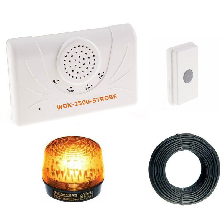
2 Warning: This device complies with Part 15 of the FCC rules, operation of this device is subject to the following conditions: 1. This device may not cause harmful interference. 2. This device must accept any interference, including interference that may cause undesired operation. introduction: The WDK-2500-STROBE is a long range doorbell/entry alert kit designed for businesses, warehouses, shops, etc. There are two major components of the kit and that is the UT-2500 transmitter and the DCR-2500 receiver. The other two pieces of the kit are accessories, an amber colored strobe light and bellwire to connect the strobe to the receiver. operation: The first part of this manual will cover the two major components of the kit. The DCR-2500 plug-in receiver and the UT-2500 transmitter (push button or door/window contact). 1. Connect the end of the power supply to the receiver (Figure 1-1). 2. Plug the power supply into a wall outlet 3. Locate the off/on switch and move to the on position (Figure 1-2). 2

3 Figure For maximum range between the transmitter and receiver, the receiver should be mounted horizontally on a wall and as high off the floor as possible. Although the maximum range is about ½ mile, things such as hills, trees, metal siding and stucco can all reduce the range. 3
4 Coding the receiver: 1. Open the receiver case by inserting a small screw driver into one of the pry notches on the side of the case. 2. Gently lift off the front cover. 3. Locate the 8 dip switches on the receiver (Figure 1-3) and make sure they are set identical to the first 8 dip switches on the transmitter. Note: If more than one transmitter is used with the receiver, the first 8 dip switches of all transmitters must match the 8 dip switches of the receiver. NOTE: Whenever a change is made to the jumpers or the dip switches, the receiver must be turned OFF and then back ON to operate properly. Coding the transmitter: 1. Locate the dip switches in the 2500 series transmitter. (refer to transmitter manual) 2. The first 8 dip switches are for the frequency setting (256 combinations). Set the first 8 switches to match the 8 switches in the receiver. 3. Switches 9 & 10 are for the zone/channel setting on the transmitter. The four zones are as follows: 4 Switch 9 Switch 10 Channel Tune On On 1 Classical Off On 2 Westminster On Off 3 Ding Dong Off Off 4 Whistle
5 Tone, relay and voltage output: 1. Each of the four transmitter zones (selectable by switch 9 & 10) will sound a tone and activate the corresponding relay on the receiver. 2. The form C relays are rated for 24 VDC at 3 Amp maximum current. 3. The 12 VDC output has a maximum current capacity of 400mA. To select the zone(s) that will activate the 12 VDC output, locate the jumper J1 (Figure 1-4) and set the jumper to cover both pins on the selected zones. If the pins are not connected by the jumper, that zone will not activate the 12VDC output. 4. The relays and voltage can be set to activate for 1 second, 10 seconds, 60 seconds or 10 minutes. To change the output duration, locate the jumper J4 (Figure 1-7) and move it to the desired time. Note: This jumper only changes the duration of the relay activation. The tone will only sound for several seconds regardless of how the jumper is set. HOW TO CONNECT THE STROBE TO THE RECEIVER The strobe connects to the receiver using the live 12VDC output. See step 3 above. 1. The included bundle of bellwire may be used to expand the distance of the strobe from the receiver. It is completely acceptable to use the wire leads on the strobe and not use the included bellwire if the length is acceptable. 2. If you want to use the bellwire, you will need to cut two equal lengths, one for the positive (+) lead and one for the negative (-). 3. See FIGURE 1 above. Use the BLACK wire on the strobe light for the (-) and the RED wire for the (+). 4. The relays and voltage can be set to activate for 1 second, 10 seconds, 60 seconds or 10 minutes. To change the output duration, locate the jumper J4 (Figure 1-7) and move it to the 5 desired time. Note: This jumper only changes the duration of the relay activation. The tone will only sound for several seconds regardless of how the jumper is set.
6 Zone Lights: The receiver has a red led light for each of the four zones. The lights can be set to blink for every activation up to ten and then repeat or turn on once for ten seconds when a signal is received. 1. To have the leds flash once for ten seconds push the C button (Figure 1-8) for 0.5 seconds and release. The four leds will flash once and the zone led will turn on for ten seconds when a signal is received. 2. To have the zone led flash for each signal received (up to ten) and then repeat, press the C button for 0.5 seconds a second time and the four leds will flash twice. 3. To reset the flashing leds press and hold the C button for 2 seconds. The four leds will light for three seconds and the flashing will stop until the next signal is received. Reminder Beep: The receiver has a reminder beep that can be set to beep every 15 minutes after a signal is received. The reminder can be set with the A button (Figure 1-10). 1. The reminder beep will only sound if the zone light is set to flash (see previous section on Zone Lights). 2. To activate the reminder beep press and hold the A button for 2 seconds. You will hear one beep. 3. To deactivate the reminder beep press and hold the A button for two seconds and you will hear two beeps. 6
7 4. To cancel the reminder beep press the A button for 0.5 seconds. 5. You can also use jumper J2 (Figure 1-5) in the receiver to select which zones will have the reminder beep. If the jumper covers both pins for a zone, that zone will have the reminder beep. If the jumper is on only one pin, the zone will not have the reminder beep. Exit Delay: The receiver can be programmed to have a 5 minute exit delay where it will not receive a signal from selected transmitters. 1. The jumper J3 (Figure 1-6) can be used to determine which zone(s) you would like to use with the exit delay. To use the exit delay set the jumper to cover both pins for the desired zone(s). 2. To start the exit delay press the B button (Figure 1-9) for 0.5 seconds and release. The green led will flash for 5 minutes and during this time no signals will be received from the selected zones. NOTE: Whenever a change is made to the jumpers or the dip switches, the receiver must be turned OFF and then back ON to operate properly. Frequency: MHz Operating voltage: 12VDC 12 volt DC output current: 400 ma maximum Relay rating: 24VDC at 3 Amp 7
8 8

 or normally closed (N/C) input.")
 for a few seconds, or")
 2. Install the CR-2 battery in the holder 3. Set the dip switches 1-8 on the transmitter module to match the receiver. 4.")
9 UT-2500 Universal Transmitter Owner s Manual Warnings This device complies with Part 15 of the FCC rules, Operation of this device is subject to the following conditions: 1. This device may not cause harmful interference. 2. This device must accept any interference, including interference that may cause undesired operation. Introduction The UT-2500 transmitter is compatible with the DCR-2500 receiver. The UT-2500 has several methods of activation. First, it has a push button that can be used as a panic button or doorbell. The UT-2500 also has terminals for a normally open (N/O) or normally closed (N/C) input. These inputs can be used with any detector contacts. There is also a magnetic contact that can be used for doors or windows. When the transmitter is activated, it will send a signal to the receiver which will sound one of four different tones (Classical, Westminster Chime, Ding Dong, or Whistle) for a few seconds, or activate the relay outputs. Operation: (Always test unit prior to installation) 1. Remove the four screws on the back of the case and open to find the battery compartment and dip switches. (Figure 1) 2. Install the CR-2 battery in the holder 3. Set the dip switches 1-8 on the transmitter module to match the receiver. 4. Set dip switches 9 and 10 to control the desired zone, tune, and relay output. (See Coding the transmitter for info on setting the dip switches.) Installing the battery: (Figure 1) 1. Use only a CR-2, 3 Volt Lithium battery. 2. Be sure to observe proper polarity when installing the battery. LED indicator light in button: 1. The default setting is for the LED indicator to light up for two seconds when the UT-2500 is activated. 2. To deactivate the LED, press and hold the push button while installing the battery. 3. To return to the default LED setting remove the battery and then re-install the battery. Coding the transmitter: 1. Open the transmitter. 2. Locate the 10 dip switches in the transmitter (Figure 2). (Figure 2) 3. The first eight dip switches are for the frequency setting (256 combinations). Set switches 1-8 to match the eight switches in the receiver. 4. Switches 9-10 are for the zone/channel setting on the transmitter. The four zones are as follows: Switch 9 Switch 10 Channel Tune On On 1 Classical Off On 2 Westminster On Off 3 Ding Dong Off Off 4 Whistle 5. After any changes are made to the dip switches, the battery must be disconnected and then reconnected for changes to take effect. Connecting an exterior detector: The UT-2500 can be activated by any type of detector which provides a normally open (N/O) or normally closed (N/C) output. 1. Locate the terminals at the bottom of the case. (Figure 3) 2. Insert the wires through the silicone gasket and make the connections on the terminals. Note: a 22 AWG solid wire can be used to easily pierce the silicone gasket. If t e r m i n a l s using a lighter wire you may need to (Figure 3) pierce the gasket with a paper clip or small needle. 3. For a normally closed (N/C) connection, connect the wires to the NC and Common (center) terminals. 4. For a normally open (N/O) connection, connect the wires between the NO and Common (center)terminals. UT2500 manual.indd 1 1/3/2013 4:18:50 PM
 with the screws provided. 3. After mounting the magnet on the door snap the cover on the magnet case. (Figure 4) 4.")
 Using multiple detectors: If multiple normally closed (N/C) contacts are to be used, they should be run in series to the N/C contacts.")
10 Using the magnetic contact: The magnetic contact can be used on most doors/windows with a gap of less than ½ inch. 1. Mount the push button on the door jam with the screws provided. 2. Mount the magnet on the door (within ½ of the push button) with the screws provided. 3. After mounting the magnet on the door snap the cover on the magnet case. (Figure 4) 4. The magnetic contact can be used on either side of the push button. (Figure 4) Using multiple detectors: If multiple normally closed (N/C) contacts are to be used, they should be run in series to the N/C contacts. If multiple normally open (N/O) contacts are used, they should be run in parallel to the N/O contacts. Note: Both N/O and N/C contacts can be used simultaneously along with the magnetic contact and push button. Mounting the transmitter: The transmitter can be mounted to any wall using the mounting bracket. (Figure 5) The mounting bracket is located on the back of the UT-2500 and can be removed by simply sliding it off. Position the bracket were you would like it and place two screws in the holes provided. To place the UT-2500 back simply slide it over the bracket. ut back cover (Figure 5) mounting bracket If mounting the UT-2500 outdoors it is recommended to place the silicone plugs in the screw holes at the back of the case to prevent moisture from entering the case. Coding the receiver: 1. Open the receiver case by inserting a small screwdriver into one of the pry notches on the side of the case (refer to receiver manual) and gently lift off the front cover. 2. Locate the eight dip switches on the receiver and make sure they are set identically to dip switches 1-8 on the transmitter. Note: If more than one transmitter is used with the receiver, the first eight dip switches of all transmitters must match the eight dip switches of the receiver. Note: Whenever a change is made to the time jumper or the dip switches, the receiver must be turned OFF and then back ON to operate properly. TECHNICAL SUPPORT If you encounter any difficulty in the operation of this product after reading the manual, please contact us. You can reach us by phone at from 8:30 AM to 5:00 PM Monday through Friday (Central Standard Time). We will be happy to answer your questions and help you in any way we can. WARRANTY Dakota Alert warrants this product to be free of defects in material and workmanship for a period of one year from the date of purchase. This warranty does not cover damage resulting from accident, abuse, act of God or improper operation. If this product does become defective, simply return it to Dakota Alert. Please include a note describing the troubles along with your name and return address as well as the original sales receipt. If the product is covered under warranty it will be repaired or replaced at no charge. If it is not covered by warranty, you will be notified of any charges before work is done. Dakota Alert, Inc E. Main Street Elk Point, SD Phone: (605) Fax: (605)
TAC1 Telephone Entry System
 TAC1 Telephone Entry System 1 4 7 2 3 5 6 8 9 0 INSTALLATION MANUAL For more information: www.devancocanada.com or call toll free at 855-931-3334 SPECIFICATIONS >> CABLE REQUIREMENTS, DIMENSIONS AND CARTON
For use with QED and hardwired control panels ONLY!
 K3129-5 10/98 6128WL Keypad/Receiver INSTALLATION INSTRUCTIONS For use with QED and hardwired control panels ONLY! General Information The 6128WL Keypad/Receiver is a combination unit. It replaces a 6128
GRANT RF CONTROL CENTER INSTALLATION INSTRUCTIONS Always disconnect battery while servicing or modifying the electrical system of the vehicle.
 GRANT RF CONTROL CENTER INSTALLATION INSTRUCTIONS Always disconnect battery while servicing or modifying the electrical system of the vehicle. You will need standard hand tools, a Test Light and a Digital
Access Control Keypad for MK-DV, JB-DV
 #91173 0406 Access Control Keypad for MK-DV, JB-DV - INSTRUCTIONS - The KVI is a surface mount electronic access control keypad for use with Aiphone s MK-DV or JB-DV video door station. Designed with the
Junior Max (JR Max ) Controller
 Controller") Get more done TM Junior Max (JR Max ) Controller stations Operating Instructions Thank you for purchasing this advanced, highly featured Irritrol Junior MAX controller. The Junior MAX is the latest addition
Get more done TM Junior Max (JR Max ) Controller stations Operating Instructions Thank you for purchasing this advanced, highly featured Irritrol Junior MAX controller. The Junior MAX is the latest addition
ST8-WiFi Timer. Installation Guide and Operations Manual. English MIN M D YYYY
 ST8-WiFi Timer Installation Guide and Operations Manual AM M D YYYY English Contents ST8-WiFi Timer Installation Guide and Operations Manual Introduction Welcome to Rain Bird... 1 Timer Features... 1 Controls
2000 Series Weather Stations Analog Temperature / RH Sensor Upgrade Kit PRODUCT MANUAL KIT # 3613WDU
 2000 Series Weather Stations Analog Temperature / RH Sensor Upgrade Kit PRODUCT MANUAL KIT # 3613WDU 1 The 3613WDU Analog Temperature / RH Sensor Upgrade Kit is used to upgrade Watchdog 2000 Series Weather
By CHANNEL VISION. Flush Mount Amplifier A0350
 Spkrs Local In IR In 24VDC A0350 10 The A0350 can be used with Channel Vision s CAT5 audio hubs to provide a powerful 50Watts per channel in the listening zone. Alternatively, the A0350 can be added to
VNS2200 Amplifier & Controller Installation Guide
 VNS2200 Amplifier & Controller Installation Guide VNS2200 Amplifier & Controller Installation 1. Determine the installation location for the VNS2200 device. Consider the following when determining the
A. Section Includes: Division 1 applies to this section. Provide GPS wireless clock system, complete.
 SPECIFICATIONS GPS Wireless Clock System Section 16730 TIME SYSTEM PART 1 - GENERAL 1.01 SUMMARY A. Section Includes: Division 1 applies to this section. Provide GPS wireless clock system, complete. B.
SBL Series Wireless Clock Installation Manual (V2) Table of Contents
 Table of Contents") MOUNTING Table of Contents Wall Mount Installation... Page 2 Double Mount Installation...... Page 3-4 WIRING AND JUMPERS Wiring Information and Jumper Settings... Page 5 FREQUENTLY ASKED QUESTIONS SBL
MOUNTING Table of Contents Wall Mount Installation... Page 2 Double Mount Installation...... Page 3-4 WIRING AND JUMPERS Wiring Information and Jumper Settings... Page 5 FREQUENTLY ASKED QUESTIONS SBL
Single Station Waterproof Timer
 Single Station Waterproof Timer Installation and Programming Guide Features Up to four irrigation cycles per day Easy installation and programming Battery powered Waterproof and weather resistant 1234
AB-114 / AB-202 AB-404 / AB-301 AB-T2454 Multi-room audio distribution system AB-202
 by By C HANNEL V ISION system AB-114 / AB-404 / AB-01 AB-T2454 Multi-room audio distribution system IN OUT 1 2 4 WHT/ WHT/ L AUDIO R 12VDC A-BUS OUTPUT IR IR EMITTERS C HANNEL V ISION 24 Fischer Avenue
COMFORT COMFORT CALL OWNER S MANUAL CALL SYSTEM P/N P BASE STATION & RF WIRELESS MODULE. Complete Control from TOTALINE
 OWNER S MANUAL COMFORT CALL SYSTEM P/N P374-0433 COMFORT BASE STATION & RF WIRELESS MODULE CALL TOTALINE REMOTE THERMOSTAT ACCESS Compatible with thermostat models: P374-700, P374-800, P374-900, P374-2700,
Table of contents. Opening the Overhead Monitor... 4 Precautions Care And Maintenance... 5 Operating OHM102/153 Monitor...
 Warning! The Clarion OHM102/OHM153 overhead monitor systems are designed for strictly for rear seat entertainment. Viewing the monitor while operating a motor vehicle can result in serious injury and/or
Installation Instructions
 SuperBus 2000 Concord 4 GSM Module 466-2262A October 2006 Copyright 2006, GE Security Inc. Introduction This is the GE SuperBus 2000 Concord 4 GSM Module Installation Instructions for part number 600-1053.
2 CHANNEL RECEIVER DISPLAY POTENTIOMETER COM2 NC2 NO2
 2 CHANNEL RECEIVER RECTSHIVE915-DX Please read this manual carefully before installing the product. 1 DESCRIPTION Receiver Rolling Code, 2 channels with dry contact relay output 20A a 12 Vdc. Programming
Automotive 72 Exterior Smart Lighting Kit
 PACKAGE CONTENTS Automotive 72 Exterior Smart Lighting Kit 36 36 8 x Wire Mounting Bracket 16 x Screws 60" Extension Cable 24 ON / OFF 60 Exterior Kit can also function as interior lighting Instruction
M150SP USER S AND INSTALLER S MANUAL. v2.0 REV. 03/2017
 M150SP USER S AND INSTALLER S MANUAL v2.0 REV. 03/2017 00. CONTT 01. SAFETY INSTRUCTIONS INDEX 01. SAFETY INSTRUCTIONS STANDARDS TO FOLLOW 02. THE DEVICE TECHNICAL SPECIFICATIONS VISUAL ASPECT CONNECTORS
Installation Instructions
 Bell Ringer OVERVIEW Thank you for choosing a TimeTrax Sync 5300 Bell Ringer. The TimeTrax Sync 5300 directs bells and horns (sold separately) to promote accountability, productivity and punctuality with
TIMETRAX SYNC RF WIRELESS DIGITAL CLOCK Installation Instructions
 Installation Instructions OVERVIEW Thank you for choosing a TimeTrax Sync RF Wireless Clock System. The TimeTrax RF Wireless Clock System receives dependable, accurate time from the TimeTrax Sync RF Wireless
Expand Your Factory Radio add Satellite Radio Harness Connection
 Expand Your Factory Radio Harness Connection add Satellite Radio Dip Switches Port 1 Port 2 (See Manual) USB Honda/Acura Owner s Manual GateWay Owner s Manual Media ISSR12 GateWay PXAMG 01-22-13 Table
Electronic 1-Circuit 7-Day Time Switch With 100-Hour Backup
 MODELS ET2705C, ET2705CR, ET2705CP Installation and Setup Instructions Electronic 1-Circuit 7-Day Time Switch With 100-Hour Backup WARNING Risk of Fire or Electric Shock Disconnect power at the circuit
Chapter 1 : FCC Radiation Norm...3. Chapter 2 : Package Contents...4. Chapter 3 : System Requirements...5. Chapter 4 : Hardware Description...
 Table of Contents Chapter 1 : FCC Radiation Norm...3 Chapter 2 : Package Contents...4 Chapter 3 : System Requirements...5 Chapter 4 : Hardware Description...6 Chapter 5 : Charging Your Video Watch...7
VNS2210 Amplifier & Controller Installation Guide
 VNS2210 Amplifier & Controller Installation Guide VNS2210 Amplifier & Controller Installation 1. Determine the installation location for the VNS2210 device. Consider the following when determining the
VMA ACTIVE MATRIX TFT COLOR LCD MONITOR OWNER S MANUAL INSTALLATION GUIDE
 VMA6491 6.4 ACTIVE MATRIX TFT COLOR LCD MONITOR OWNER S MANUAL INSTALLATION GUIDE OWNER S MANUAL WARNING! THE CLARION VMA6491 LCD MONITOR IS DESIGNED FOR REAR SEAT PASSENGER VIEWING ONLY. THIS PRODUCT
ULTRA-TRAC APL INSTRUCTION MANUAL. Read and understand instructions before use. Patented. 851 Transport Drive Valparaiso, IN
 ULTRA-TRAC APL A C O U S T I C P I P E L O C A T O R INSTRUCTION MANUAL Read and understand instructions before use. Patented MADE IN USA 851 Transport Drive Valparaiso, IN 46383-8432 Phone: 888 4SENSIT
MWT-FM. Operation Manual. FM Single Channel Transmitter. man_mwtfm.
 MWT-FM FM Single Channel Transmitter Operation Manual man_mwtfm www.myeclubtv.com CONTENTS FCC COMPLIANCE STATEMENT. 3 INDUSTRY CANADA COMPLIANCE 3 MWT-FM ORIENTATION. 4 SAFETY PRECAUTIONS 5 FINDING FM
Scale Track System. 21 Century y Signal System 2-Rail Manual
 Scale Track System st 21 Century y Signal System 2-Rail Manual TABLE OF CONTENTS Introduction...2-3 Road Signal Board Diagram and Definitions...4-6 Tips for Handling the Circuit Board...6 2-Rail Detector
Doorphone Video Intercom
 HOME SERIES INSTRUCTION MANUAL Doorphone Video Intercom with Colour 4.3 LCD Monitor EN Getting to know your LCD Screen (Front) 1 2 3 4 5 6 1) LCD Screen - This is where you view your visitor that the intercom
VGA Extender over Single CAT 6 Cable with Audio Support. Model Extend both video and audio up to 1000 feet
 VGA Extender over Single CAT 6 Cable with Audio Support Model 103004 Extend both video and audio up to 1000 feet Utilize a Cat 6 cable instead of a bulky VGA cable Supports a local monitor and local speakers
TITLE BOX PAGE ONLY. DO NOT MAKE FILM DO NOT PRINT
 REV DESCRIPTION INT: REV. DATE APPROVED 1 ECO# CO1790 MJS 9/27/06 CG 2 ECO# 02412 DR 10/3/07 CG 3 ECO# 03170 MJS TITLE BOX PAGE ONLY. DO NOT MAKE FILM DO NOT PRINT MATERIAL: White 16lb (60g/m sq), uncoated,
USER MANUAL FOR THE ANALOGIC GAUGE FIRMWARE VERSION 1.0
 by USER MANUAL FOR THE ANALOGIC GAUGE FIRMWARE VERSION 1.0 www.aeroforcetech.com Made in the USA! WARNING Vehicle operator should focus primary attention to the road while using the Interceptor. The information
RT505TX Programmable. The RT505TX can be used with any of these receivers RXBC605 RXWBC605 RXVBC605 RXST MHz
 RT505TX T RT505 T505TX TX RT505TX RT505TX RT505TX 5TX Programmable Room o Thermostat RXBC605 RXRT505 RXWBC605 RXST625 RXVBC605 The RT505TX can be used with any of these receivers 868MHz RT505TX RT505TX
AES-402 Automatic Digital Audio Switcher/DA/Digital to Analog Converter
 Broadcast Devices, Inc. AES-402 Automatic Digital Audio Switcher/DA/Digital to Analog Converter Technical Reference Manual Broadcast Devices, Inc. Tel. (914) 737-5032 Fax. (914) 736-6916 World Wide Web:
Electronic 2-Circuit 24-Hour Time Switch With 100-Hour Backup
 MODELS ET2125C, ET2125CR, ET2125CP Installation and Setup Instructions Electronic 2-Circuit 24-Hour Time Switch With 100-Hour Backup WARNING Risk of Fire or Electric Shock Disconnect power at the circuit
OWNER S MANUAL MOTORIZED 7 WIDE TFT LCD COLOR MONITOR CNT-701
 OWNER S MANUAL PW MOTORIZED 7 WIDE TFT LCD COLOR MONITOR CNT-701 ANY CHANGES OR MODIFICATIONS IN CONSTRUCTION OF THIS UNIT DEVICE WHICH IS NOT APPROVED BY THE PARTY RESPONSIBLE FOR COMPLIACE COULD VOID
USER MANUAL FOR THE ANALOGIC GAUGE FIRMWARE VERSION 1.1
 by USER MANUAL FOR THE ANALOGIC GAUGE FIRMWARE VERSION 1.1 www.aeroforcetech.com Made in the USA! WARNING Vehicle operator should focus primary attention to the road while using the Interceptor. The information
Multi-Zone Programmable RGB ColorPlus LED Touch Controller (Remote Control) and RGB ColorPlus LED Touch Controller (Receiver)
 and RGB ColorPlus LED Touch Controller (Receiver)") 11235 West Bernardo Court, Suite 102 San Diego, CA 92127 888-880-1880 Fax: 707-281-0567 EnvironmentalLights.com Multi-Zone Programmable RGB ColorPlus LED Touch Controller (Remote Control) and RGB ColorPlus
11235 West Bernardo Court, Suite 102 San Diego, CA 92127 888-880-1880 Fax: 707-281-0567 EnvironmentalLights.com Multi-Zone Programmable RGB ColorPlus LED Touch Controller (Remote Control) and RGB ColorPlus
HD Digital Set-Top Box Quick Start Guide
 HD Digital Set-Top Box Quick Start Guide Eagle Communications HD Digital Set-Top Box Important Safety Instructions WARNING TO REDUCE THE RISK OF FIRE OR ELECTRIC SHOCK, DO NOT EXPOSE THIS PRODUCT TO RAIN
INSTALLATION INSTRUCTIONS FOR. MODEL 2230LED
 INSTALLATION INSTRUCTIONS FOR MODEL 2230LED www.sportablescoreboards.com 1 Table of Contents MODEL 2230LED... 3 8 X 4 INDOOR SCOREBOARD... 3 THE SCOREBOARD SYSTEM SHOULD INCLUDE THE FOLLOWING PARTS:...
RD RACK MOUNT DIMMER OWNERS MANUAL VERSION /09/2011
 RD - 122 RACK MOUNT DIMMER OWNERS MANUAL VERSION 1.3 03/09/2011 Page 2 of 14 TABLE OF CONTENTS UNIT DESCRIPTION AND FUNCTIONS 3 POWER REQUIREMENTS 3 INSTALLATION 3 PLACEMENT 3 POWER CONNECTIONS 3 OUTPUT
FPV PRO RACE EDITION TRI-DIVERSITY VIDEO CONTROLLER
 DIVERSITY DEMON FPV PRO RACE EDITION TRI-DIVERSITY VIDEO CONTROLLER Diversity Demon is a video controller that is used to bridge three wireless video receivers together. Multiple receivers are used to
Quick Start Guide ABOUT THE CAMERA
 User Manual Quick Start Guide ABOUT THE CAMERA A Record Status B Record Switch C Rotating Lens D Battery Slot E Battery Latch F Card Format Button G USB H Format Switch I MicroSD card J Memory Status K
ROUGH DRAFT. Guide. Installation. Signal Booster. Wilson. AG Pro 75 Smart Technology In-Building Wireless 800/1900 Signal Booster.
 Signal Booster Installation Guide Contents: AG Pro 75 Smart Technology In-Building Wireless 800/1900 Signal Booster Before Getting Started.... 1 Antenna Options & Accessories.................... 1 Easy
RemotePoint. Navigator. User s Manual VP4150
 RemotePoint Navigator User s Manual VP4150 LASER Safety Statement CAUTION: Use of controls or adjustments or performance of procedures other than those specified herein may result in hazardous radiation
TV55. Owner s Manual. Indoor/Outdoor Amplified TV Antenna
 Owner s Manual Indoor/Outdoor Amplified TV Antenna Safety Precautions Warning! Use extreme caution when installing or removing an outdoor antenna that is located close to overhead wires such as power lines,
Model Extend HDMI audio and video connections up to 300 feet. Add up to 8 additional receivers with a dedicated network switch
 HDMI Extender over Single CAT 6 Cable with IR Control Model 103002 Extend HDMI audio and video connections up to 300 feet Utilize existing Cat 6 wiring for an easy installation Add up to 8 additional receivers
VGA Extender LR EXT-VGA-141LR. User s Manual
 VGA Extender LR EXT-VGA-141LR User s Manual ASKING FOR ASSISTANCE Technical Support: Telephone (818) 772-9100 (800) 545-6900 Fax (818) 772-9120 Technical Support Hours: 8:00 AM to 5:00 PM Monday thru
ARS x4 MATRIX SWITCHER Instruction Manual
 ARS-8400 8x4 MATRIX SWITCHER Instruction Manual Thank you for purchasing one of our products. Please read this manual before using this product. When using this product, always follow the instructions
Concord 4 GSM Module Installation Sheet
 600-1053-3 Concord 4 GSM Module Installation Sheet Description Component Function The module interfaces with the Concord panel data bus and is powered by the panel battery or an auxiliary 12 VDC power
Conference Speaker Timing System. Operating Instruction Manual
 Conference Speaker Timing System Operating Instruction Manual December 2006 Table of Contents Overview... 2 The Master Station... 2 The Slave Station... 2 Warning Lights... 3 Radio-Controlled Clock...
Read all precautions and instructions in this manual before you begin using this equipment. Please keep this manual for future reference.
 Indoorcycling Group GmbH Happurger Strasse 84-88 90482 Nuernberg Germany info@indoorcycling.com Wireless Commercial Computer - PRO 1.0 Articel no. ST 020120 Articel no. 020120 Caution! Read all precautions
Guide. Installation. Signal Booster. Wilson. DB Pro Adjustable Gain 800/1900 MHz In-Building Wireless Smart Technology
 Signal Booster Installation Guide DB Pro Adjustable Gain 800/1900 MHz In-Building Wireless Smart Technology Signal Booster DB Pro Contents: How it Works... 1 Quick Install Overview.... 2 Installation Diagram....
Bell and Light System tm RF Remote Control
 Bell and Light System tm RF Remote Control Copyright 2017, Professional Sound Corp. All Rights Reserved Thank you for purchasing the Professional Sound Corporation Bell and Light System RF Remote Control.
VGA Extender over Cat 6 with Audio Support. Model Extend both video and audio up to 300 meters
 VGA Extender over Cat 6 with Audio Support Model 103004 Extend both video and audio up to 300 meters Utilize a Cat 6 cable instead of a bulky VGA cable Supports a local monitor and local audio Easy installation
ACCESSORIES MANUAL PART NUMBER: TNP500. Universal Tilt N Plug Interconnect Box USER'S GUIDE
 MANUAL PART NUMBER: 400-0091-003 TNP500 Universal Tilt N Plug Interconnect Box USER'S GUIDE INTRODUCTION Your purchase of the TNP100 Tilt N Plug Interconnect Box is greatly appreciated. We are sure you
ENG-44 Field Portable Audio Mixer. Operator s Manual. SignVideo SE Gideon Street - Portland, Oregon
 Field Portable Audio Mixer Operator s Manual SignVideo - 1226 SE Gideon Street - Portland, Oregon 97202 503.236.0000 www.signvideo.com Safety Warning Protect your ears. Always turn down the headphone volume
INSTRUCTION MANUAL. Heart Rate Monitor. English. Model HR-100CAN ST/SP SET MODE TIME
 INSTRUCTION MANUAL Heart Rate Monitor Model HR-100CAN ST/SP SET MODE TIME English TABLE OF CONTENTS Before Using the Monitor Introduction...3 Components and Functions...4 Your Personal Data Maximum Heart
QUICK START GUIDE SL-6. Powering and Wireless System for the 688 Field Production Mixer
 QUICK START GUIDE Powering and Wireless System for the 688 Field Production Mixer Welcome Thank you for purchasing the, the powering and wireless system that simplifies interconnection between the 688
900-Lumen Portable LED Projector Part #: User manual
 900-Lumen Portable LED Projector Part #: 21797 User manual 900-Lumen LED Projector Manual Page 2 of 14 900-Lumen LED Projector Manual Page 3 of 14! SAFETY WARNINGS AND CAUTIONS WARNING: To reduce the risk
User Manual. SWIT ELECTRONICS CO., LTD Model: S-4904P Wireless HD Transmission System(with Panel Receiver) Ver:A
 Ver:A") SWIT ELECTRONICS CO., LTD Model: S-4904P Wireless HD Transmission System(with Panel Receiver) User Manual Ver:A Please read this User Manual throughout before using Preface 1. All internal technologies
SWIT ELECTRONICS CO., LTD Model: S-4904P Wireless HD Transmission System(with Panel Receiver) User Manual Ver:A Please read this User Manual throughout before using Preface 1. All internal technologies
K9123, K9134, K9135 Remote Programming Instructions and Specifications
 K9123, K9134, K9135 Remote Programming Instructions and Specifications 12 Volt Signal Ground Signal Plug Door Push & Hold K9123 K9134 K9135 Before pairing the receiver to the remotes, the receiver must
SR - 516D DESK TOP DMX REMOTE STATION. Version: Date: 05/16/2013
 SR - 516D DESK TOP DMX REMOTE STATION Version: 1.10 Date: 05/16/2013 Page 2 of 10 TABLE OF CONTENTS DESCRIPTION 3 POWER REQUIREMENTS 3 INSTALLATION 3 CONNECTIONS 3 POWER CONNECTIONS 3 DMX CONNECTIONS 3
Owner's Manual DIGITAL TO ANALOG BROADCAST CONVERTER WITH REMOTE CONTROL. Model: CVD508 PLEASE READ BEFORE OPERATING THIS EQUIPMENT.
 Size: 148.5(W) x 210(H)mm (A5) DIGITAL TO ANALOG BROADCAST CONVERTER WITH REMOTE CONTROL Owner's Manual PLEASE READ BEFORE OPERATING THIS EQUIPMENT. Model: CVD508 FCC NOTICE: To assure continued compliance,
Fully ly Automaticti. Motorised Satellite t TV System. User s manual REV
 REV. 1.0 Fully ly Automaticti Motorised Satellite t TV System User s manual Customer Help Line: 1300 139 255 Support Email: support@satkingpromax.com.au Website: www.satkingpromax.com.au www.satkingpromax.com.au
Manual No: Revision: D. IQ Box. Software Upgrade Instructions
 Manual No: 577013-834 Revision: D IQ Box Software Upgrade Instructions Notice Veeder-Root makes no warranty of any kind with regard to this publication, including, but not limited to, the implied warranties
WCM-758G. user MANUAL
 SKYVISION WCM-758G WIRELESS 7" MONITOR user MANUAL 2 INTRODUCTION Thank you for choosing Elvid. The Elvid WCM-758G SkyVision is a wireless monitor designed to receive signal from your 5.8 GHz composite
AES-404 Digital Audio Switcher/DA/Digital to Analog Converter
 Broadcast Devices, Inc. AES-404 Digital Audio Switcher/DA/Digital to Analog Converter Technical Reference Manual Broadcast Devices, Inc. Tel. (914) 737-5032 Fax. (914) 736-6916 World Wide Web: www.broadcast-devices.com
Evolution Digital HD Set-Top Box Important Safety Instructions
 Evolution Digital HD Set-Top Box Important Safety Instructions 1. Read these instructions. 2. Keep these instructions. 3. Heed all warnings. 4. Follow all instructions. 5. Do not use this apparatus near
Touch Panel RGB LED Controller Part No. touch-panel-rgb
 11235 West Bernardo Court, Suite 102 San Diego, CA 92127 888-880-1880 Fax: 707-281-0567 EnvironmentalLights.com Touch Panel RGB LED Controller Part No. touch-panel-rgb The Touch Panel RGB LED Controller
User Manual. Snowsport Speedometer. Snowsport Speedometer. Snowsport Speedometer. Table of Contents: 1. Quick Start Guide
 Table of Contents: User Manual 1. Quick Start Guide READ THIS FIRST If at any point in these instructions you have questions, please call +49 (0)89 30725599 or write an e-mail to service@microsport.de.
INSTALLATION INSTRUCTIONS MODEL VSBX-236 LED 3 X 8 INDOOR SCOREBOARD
 1 INSTALLATION INSTRUCTIONS MODEL VSBX-236 LED 3 X 8 INDOOR SCOREBOARD NOTE TO INSTALLERS: PLEASE RETURN THIS MANUAL TO THE INDIVIDUAL IN CHARGE OF THE SCOREBOARD UPON COMPLETION OF INSTALLATION. The scoreboard
USER MANUAL. 22" Class Slim HD Widescreen Monitor L215DS
 USER MANUAL 22" Class Slim HD Widescreen Monitor L215DS TABLE OF CONTENTS 1 Getting Started Package Includes Installation 2 Control Panel / Back Panel Control Panel Back Panel 3 On Screen Display 4 Technical
A0325. ARIA Audio Streaming Source Receiver with a built in Bluetooth 4.2 Module. ARIA Audio
 A0325 ARIA Audio Streaming Source Receiver with a built in Bluetooth 4.2 Module ARIA Audio by 2017 Model A0325 Channel Vision s ARIA Audio Streaming Receiver is equipped with a Blue tooth 4.2 module, users
Operating Instructions DCI-50-CT Cable Identifier
 Operating Instructions DCI-50-CT Cable Identifier 1 CAUTION The equipment covered in these operating instructions should be used by qualified employees, trained in and familiar with the safety-related
USER S MANUAL. Deuce HD User's Manual WORLD HEADQUARTERS
 USER S MANUAL WORLD HEADQUARTERS Artel Video Systems 5B Lyberty Way Westford, MA 01886 Tel: (978) 263-5775 Fax: (978) 263-9755 Email: info@artel.com Web: www.artel.com P/N 1219 Rev. F Copyright 2016 USER
Operating Instructions DCI-50-CT Cable Identifier
 Operating Instructions DCI-50-CT Cable Identifier 1 CAUTION The equipment covered in these operating instructions should be used by qualified employees, trained in and familiar with the safety-related
INSTALLATION INSTRUCTIONS FOR
 INSTALLATION INSTRUCTIONS FOR MODEL 2240LED www.sportablescoreboards.com 1 Table of Contents 8 X 7 INDOOR SCOREBOARD... 3 THE SCOREBOARD SYSTEM SHOULD INCLUDE THE FOLLOWING PARTS:... 3 INSTRUCTIONS FOR
CAUTION RISK OF ELECTRIC SHOCK NO NOT OPEN
 Evolution Digital HD Set-Top Box Important Safety Instructions 1. Read these instructions. 2. Keep these instructions. 3. Heed all warnings. 4. Follow all instructions. 5. Do not use this apparatus near
TP HDMI OVER ANYWIRE RECEIVER (DC)
") HDMI OVER ANYWIRE RECEIVER (DC) Welcome! Everyone at Altinex greatly appreciates your purchase of the TP315 106. We are confident that you will find it to be reliable and simple to use. If you need support,
HDMI OVER ANYWIRE RECEIVER (DC) Welcome! Everyone at Altinex greatly appreciates your purchase of the TP315 106. We are confident that you will find it to be reliable and simple to use. If you need support,
LBS-1 (Lowrance Broadband Sounder)
") Pub. 988-0170-001 LBS-1 (Lowrance Broadband Sounder) Installation Instructions The LBS-1 is a digital sonar optimizer designed to enhance sonar echo clarity. The broadband sounder was created to deliver
Pub. 988-0170-001 LBS-1 (Lowrance Broadband Sounder) Installation Instructions The LBS-1 is a digital sonar optimizer designed to enhance sonar echo clarity. The broadband sounder was created to deliver
HDMI 5x1 Switch B-240-HDSWTCH-5X1 INSTALLATION MANUAL
 HDMI 5x1 Switch B-240-HDSWTCH-5X1 INSTALLATION MANUAL IMPORTANT SAFETY INSTRUCTIONS To reduce the risk of fire or electric shock, read and follow all instructions and warnings in this manual. Keep this
 Register your product and get support at www.philips.com/welcome SDV8625T/27 User manual Contents 1 Important 4 Safety 4 For indoor use 4 For outdoor use 4 Notice for USA 4 Notice for Canada 5 Recycling
OWNER'S MANUAL SIGNAL COMMANDER
 OWNER'S MANUAL SIGNAL COMMANDER THIS MANUAL CONTAINS INSTRUCTIONS FOR: LPDA 100 - INSTALLATION - OPERATION - TROUBLESHOOTING - EXPLODED PARTS DIAGRAM - WARRANTY AntennaTek, Inc. 425 S. Bowen, # 4 Longmont,
USERS GUIDE MCX-HTS. HDMI to 3G SDI Converter. Manual Number:
 USERS GUIDE MCX-HTS HDMI to 3G SDI Converter i Manual Number: 151226 SAFETY INSTRUCTIONS Please review the following safety precautions. If this is the first time using this model, then read this manual
How do I delete a. Remove Here
 2 3 4 5 6 Q. A. Frequently Asked Questions Please read before calling Customer Service. Does your system run repeatedly? Q. How do I delete a start time? Q. Where do I leave the LARGE dial? Do NOT set
Elite Silvermax Series
 Electric Projection Screen Elite Silvermax Series USER S GUIDE IMPORTANT SAFETY INSTRUCTIONS Please read this guide prior to installation. Make sure the current rating is equal to the appliance rating
Guide. Installation. Mobile Wireless Amplifier Kit with Phone Cradle. Contents:
 Amplifier Kit Installation ti Guide Mobile Wireless Amplifier Kit with Phone Cradle Contents: Guarantee and Warranty 1 How it Works 2 Before Getting Started 3 Installing the Magnet Mount Antenna 4 Installing
Arbor Scientific PO Box 2750 Ann Arbor, Michigan (800) Timer & Photogates 2.0 P Owners Manual
 Timer & Photogates 2.0 P Owners Manual") Arbor Scientific PO Box 2750 Ann Arbor, Michigan 48108 www.arborsci.com (800) 367-6695 Timer & Photogates 2.0 P4-1450 Owners Manual Stopwatch 0.01 second resolution to 999999.99 seconds Count FCC Compliance
Arbor Scientific PO Box 2750 Ann Arbor, Michigan 48108 www.arborsci.com (800) 367-6695 Timer & Photogates 2.0 P4-1450 Owners Manual Stopwatch 0.01 second resolution to 999999.99 seconds Count FCC Compliance
VLC-3 USER'S MANUAL. Light Program Controller. M rev. 04 K rev. 00 & ( ( 5, 352*5$0 1 : $ 2 ' 6(77,1*6 )81&7,216
81&7,216") Light Program Controller VLC-3 USER'S MANUAL +50,1 +50,1 1 : $ ' 2 7. 6 8 ' 5, 7 6 6. $ ( 3 352*5$0 0,16(& )81&7,216 6(77,1*6 & 8 5 5 ( 1 7 3 ( 5, 2 ' M 890-00189 rev. 04 K 895-00406 rev. 00 GENERAL...
Light Program Controller VLC-3 USER'S MANUAL +50,1 +50,1 1 : $ ' 2 7. 6 8 ' 5, 7 6 6. $ ( 3 352*5$0 0,16(& )81&7,216 6(77,1*6 & 8 5 5 ( 1 7 3 ( 5, 2 ' M 890-00189 rev. 04 K 895-00406 rev. 00 GENERAL...
USER S MANUAL. Save this manual for future reference. For a digital version of this manual, visit
 TM USER S MANUAL Save this manual for future reference. For a digital version of this manual, visit www.mylifter.com/installation. 4 5 TABLE OF CONTENTS 4 INSTALLING THE PULLEY SYSTEM FOR LIFTING 100
FlexiScan. Impro FlexiScan 4-Channel Controller INSTALLATION MANUAL
 MODEL NUMBER: HCM991-0-0-GB-XX FlexiScan SPECIFICATIONS Impro FlexiScan 4-Channel Controller INSTALLATION MANUAL Working Environment... Security... Input Voltage... The Impro FlexiScan is designed to work
SIR-GM1 GM CLASS-2 BUS COMPATIBLE SIRIUS SATELLITE RADIO TUNER
 SIR-GM1 GM CLASS-2 BUS COMPATIBLE SIRIUS SATELLITE RADIO TUNER Installation Guide Congratulations on your purchase of the SIR-GM1 the GM Compatible SIRIUS Satellite Radio Tuner! Your SIR-GM1 is designed
H270 LED MONITOR USER MANUAL
 H270 LED MONITOR USER MANUAL In order to continue serving our customers and providing the best products, our product information including our user manuals may receive updates from time to time. Please
VGA Extender LR EXT-VGA-141LR. User s Manual
 VGA Extender LR EXT-VGA-141LR User s Manual Congratulations on your purchase of the VGA Extender LR. Your complete satisfaction is very important to us. Gefen Gefen delivers innovative, progressive computer
VGA Extender SRN. EXT-VGA-141SRN User Manual.
 VGA Extender SRN EXT-VGA-141SRN User Manual www.gefen.com ASKING FOR ASSISTANCE Technical Support: Telephone (818) 772-9100 (800) 545-6900 Fax (818) 772-9120 Technical Support Hours: 8:00 AM to 5:00 PM
USER MANUAL. Kramer Electronics, Ltd. Models:
 Kramer Electronics, Ltd. USER MANUAL Models: 707, Video Audio Line Transmitter 708, Video Audio Line Receiver 709, Y/C Line Transmitter 710, Y/C Line Receiver 711xl, Video-Audio Line Transmitter 712xl,
Programmable Room Thermostat With RF
 Salus RT500RF Manual:89 10/7/10 23:43 Page 1 Programmable Room Thermostat With RF Instruction Manual Model No RT500RF 2 Salus RT500RF Manual:89 10/7/10 23:43 Page 2 PRODUCT COMPLIANCE This product complies
Extender w/ RS-232 and 2-way IR
 Extender w/ RS-232 and 2-way IR GTB-UHD2IRS-ELRPOL-BLK User Manual Release A3 Important Safety Instructions 1. Read these instructions. 2. Keep these instructions. 3. Heed all warnings. 4. Follow all instructions.