FIP-400B Series. Fiber Inspection Probe and ConnectorMax2. User Guide
|
|
|
- Kelley Barrett
- 5 years ago
- Views:
Transcription

1 FIP-400B Series Fiber Inspection Probe and ConnectorMax2 User Guide
2 Copyright EXFO Inc. All rights reserved. No part of this publication may be reproduced, stored in a retrieval system or transmitted in any form, be it electronically, mechanically, or by any other means such as photocopying, recording or otherwise, without the prior written permission of EXFO Inc. (EXFO). Information provided by EXFO is believed to be accurate and reliable. However, no responsibility is assumed by EXFO for its use nor for any infringements of patents or other rights of third parties that may result from its use. No license is granted by implication or otherwise under any patent rights of EXFO. EXFO s Commerce And Government Entities (CAGE) code under the North Atlantic Treaty Organization (NATO) is 0L8C3. The information contained in this publication is subject to change without notice. Trademarks EXFO s trademarks have been identified as such. However, the presence or absence of such identification does not affect the legal status of any trademark. Units of Measurement Units of measurement in this publication conform to SI standards and practices. Patents Feature(s) of this product is/are protected by pending design patents. Version number: ii FIP-400B Series
3 Contents Contents Certification Information... vi 1 Introducing the FIP-400B Series Fiber Inspection Probe and ConnectorMax Probe...1 Available Models...3 Probe Tips...4 LED Indicators...5 ConnectorMax2 Software...8 Technical Specifications...9 Conventions Safety Information Other Safety Symbols on Your Unit...12 Electrical Safety Information Setting up Your Fiber Inspection Probe and ConnectorMax Connecting or Disconnecting the Wireless Probe...17 Changing the Fiber Inspection Probe Tip...20 Adjusting Brightness...21 Setting up Autonaming...23 Managing and Selecting Test Configurations...31 Editing the Power Meter Test Configurations...50 Reverting to Factory Settings...52 Changing Fiber Information of Existing Captures...53 Fiber Inspection Probe iii
4 Contents 4 Inspecting Fiber Ends...55 Inspecting Fiber Ends (Single Fiber and Transceiver - Fiber Receptacles)...55 Setting Up Multifiber Inspection...59 Displaying Multifiber Connector Overlay...60 Inspecting Fiber Ends (Multifiber)...61 Retesting a Fiber (Multifiber)...68 Saving Files...70 Opening and Closing Files...73 Analyzing Captures...74 Displaying or Hiding the Power Meter and VFL Controls...79 Clearing Power Meter Measurements Automatically...80 Measuring Power or Insertion Loss...81 Viewing Power Meter Results...82 Identifying Fiber Faults Visually with the VFL...83 Creating Reports...84 Updating the Firmware and Software Maintenance...91 General Maintenance...91 Recycling and Disposal (Applies to European Union Only)...91 Recharging the Battery (FIP-425B and FIP-435 Models Only)...92 Replacing the Battery (FIP-425B and FIP-435 Models Only) Troubleshooting...97 Solving Common Problems...97 Contacting the Technical Support Group Viewing Information About ConnectorMax Viewing Online Help Transportation Warranty General Information Liability Exclusions Certification Service and Repairs EXFO Service Centers Worldwide Fiber Inspection Probe Tip Compatibility Chart iv FIP-400B Series
5 Contents A Working With the Fiber Inspection Probe in TestFlow Supported Models in TestFlow LED Indicators Connecting or Disconnecting the Wireless Probe Inspecting Fiber Ends Analyzing Captures Updating the Firmware Solving Common Problems in TestFlow Viewing Information About the FIP Index Fiber Inspection Probe v
6 Certification Information Certification Information North America Regulatory Statement This unit was certified by an agency approved in both Canada and the United States of America. It has been evaluated according to applicable North American approved standards for product safety for use in Canada and the United States. Electronic test and measurement equipment is exempt from FCC part 15, subpart B compliance in the United States of America and from ICES-003 compliance in Canada. However, EXFO Inc. makes reasonable efforts to ensure compliance to the applicable standards. The limits set by these standards are designed to provide reasonable protection against harmful interference when the equipment is operated in a commercial environment. This equipment generates, uses, and can radiate radio frequency energy and, if not installed and used in accordance with the user guide, may cause harmful interference to radio communications. Operation of this equipment in a residential area is likely to cause harmful interference in which case the user will be required to correct the interference at his own expense. Modifications not expressly approved by the manufacturer could void the user's authority to operate the equipment. vi FIP-400B Series
7 Certification Information The wireless probe comes with an internal wireless module and antenna for which the following information applies: This equipment has been tested and found to comply with the limits for a Class A digital device, pursuant to Part 15 of the FCC Rules. Operation is subject to the following two conditions: (1) This device may not cause harmful interference, and (2) this device must accept any interference received, including interference that may cause undesired operation. This device complies with Industry Canada license-exempt RSS standard(s). Operation is subject to the following two conditions: (1) this device may not cause interference, and (2) this device must accept any interference, including interference that may cause undesired operation of the device. This device complies with the US/Canada portable RF exposure limit set forth for an uncontrolled environment and is safe for intended operation as described in this user documentation. The further RF exposure reduction can be achieved if the device can be kept as far as possible from the user s body. This device does not contain any user-serviceable components. Any unauthorized product changes or modifications will invalidate warranty and all applicable regulatory certifications and approvals. Fiber Inspection Probe vii
8 Certification Information European Community Declaration of Conformity Warning: This is a class A product. In a domestic environment, this product may cause radio interference in which case the user may be required to take adequate measures. Hereby, EXFO declares that the radio equipment type Wide Band Data Transmission is in compliance with Directive 2014/53/EU. An electronic version of the complete declaration of conformity for your product is available on our website at Refer to the product s page on the Web site for details. The information about the Wi-Fi frequency bands is as follows: Between the frequencies MHz MHz. The maximum output power is 15 dbm. This device is a 2.4 GHz wideband transmission system (transceiver), intended for use in all EU member states and EFTA countries, except in France and Italy where restrictive use applies. In Italy, the end-user should apply for a license at the national spectrum authorities in order to obtain authorization to use the device for setting up outdoor radio links and/or for supplying access to telecommunications and/or network services. This device may not be used for setting up radio links in France, and in some areas the RF output power may be limited to 10 mw EIRP in the frequency range of MHz. For detailed information, the end-user should contact the national spectrum authority in France. viii FIP-400B Series

9 Certification Information Japanese Technical Conformity Mark for Radio Law Technical parameters: Standards: IEEE b/g/n Operation Frequency: 2412 ~ MHz Throughput: 150 Mbps, 1T1R R Fiber Inspection Probe ix
10
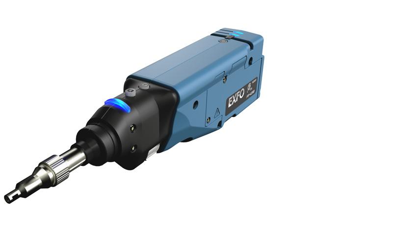
11 1 Introducing the FIP-400B Series Fiber Inspection Probe and ConnectorMax2 The FIP-400B Series Fiber Inspection Probe is a portable video microscope used to inspect fiber ends. Unlike traditional microscopes, the FIP-400B Series facilitates the examination of patchcord connectors and also hard-to-reach connectors on the back of patch panels and bulkhead adapters. Probe The FIP-400B Series is designed to be an intuitive, easy-to-use piece of equipment. This video microscope is used for inspecting fiber ends. Capture control Magnification control Status LED Retaining nut Interchangeable adapter tips Focus FIP-410B/420B/430B Fiber Inspection Probe 1
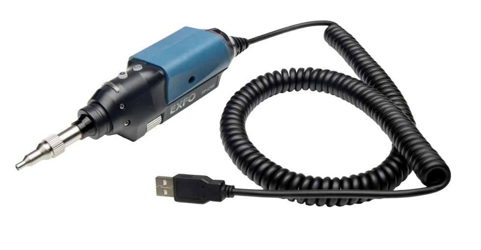
12 Introducing the FIP-400B Series Fiber Inspection Probe and ConnectorMax2 Probe Magnification control Capture control Battery LED Wi-Fi LED Status LED Micro USB adapter connector Retaining nut Battery compartment door Interchangeable adapter tips Focus FIP-425B/435B The focus knob can be turned in either direction to focus the image. The magnification control button allows you to shift between three levels of magnification. When pressed for one second, it activates the auto focus. The capture control button allows you to capture an image, perform an analysis, or return to the Live Video mode. The retaining nut holds tips securely in place, ensuring they are always fastened in the correct position. The status LED gives you information about the probe or the analysis results. The interchangeable adapter tips give you the possibility to use various tips depending on the type of connector you are inspecting. Note: This applies to the FIP-425B and FIP-435B models only. 2 FIP-400B Series
13 Introducing the FIP-400B Series Fiber Inspection Probe and ConnectorMax2 Available Models The micro USB adapter connector recharges the battery of the probe when it is low. You can recharge the battery with the provided USB cable and the adapter/charger that you connect to a power outlet. You can also use the provided USB cable alone that you connect to a USB port of a computer. When the probe is connected to a power outlet or to a USB port, it still works via Wi-Fi. The battery compartment door is for battery replacement. The probe comes equipped with a protective cap that fits over basic tips; therefore, you do not need to remove the tip before putting the cap on. Available Models The features available for your probe are automatically detected when you connect it to your unit. The table below shows which feature is available for each model. Models Inspection Auto analysis Auto centering Auto focus Auto capture Wireless FIP-410B X FIP-420B X X X FIP-425B X X X - - X FIP-430B X X X X X - FIP-435B X X X X X X Note: The auto capture is not available in multifiber mode. Note: When the internal temperature of the FIP-430B and FIP-435B is too low, the probe performs a warm-up that can last up to a minute. Fiber Inspection Probe 3
14 Introducing the FIP-400B Series Fiber Inspection Probe and ConnectorMax2 Probe Tips Probe Tips The FIP-400B Series comes with two interchangeable tips included in two different packages (UPC or APC). Additional models are also available. UPC package: FIPT-400-FC-SC: FC-SC Bulkhead tip FIPT-400-U25M: Universal patchcord tip (2.5 mm ferrule) APC package: FIPT-400-SC-APC: SC APC tip for bulkhead adapter FIPT-400-U25MA: Universal patchcord tip for 2.5 mm ferrules Other tip models are available for various bulkhead adapters and patchcord connectors. For more information about tips and their use, see the Fiber Inspection Probe Tip Compatibility Chart on page 107, or visit the EXFO Web site. 4 FIP-400B Series
15 Introducing the FIP-400B Series Fiber Inspection Probe and ConnectorMax2 LED Indicators LED Indicators The LEDs located on the probe give you information about the probe or the analysis results. FIP-410B/FIP-420B/FIP-430B Status LED LED Status Flashing blue Detection of the probe in progress Analysis in progress Waiting mode. The auto focus process starts automatically when you insert an optical fiber connector (FIP-430B only) Auto focus in progress (FIP-430B only) Probe is initializing Flashing red There is a major problem preventing the probe from functioning properly Blue Probe detected and ready On a computer, the USB port is in suspend mode Red In Capture mode, current FIP result status is Fail (FIP-420B and FIP-430B) Green In Capture mode, current FIP result status is Pass (FIP-420B and FIP-430B) Fiber Inspection Probe 5
16 Introducing the FIP-400B Series Fiber Inspection Probe and ConnectorMax2 LED Indicators Battery LED FIP-425B/ FIP-435B Wi-Fi LED Status LED Status LED Status Flashing blue Processing in progress Flashing red There is a problem with the probe. Follow the instructions on screen. The auto focus is in timeout There is an analysis error Blue The probe is ready and operational Red In Capture mode, current FIP result status is Fail. Green In Capture mode, current FIP result status is Pass. 6 FIP-400B Series
17 Introducing the FIP-400B Series Fiber Inspection Probe and ConnectorMax2 LED Indicators Battery LED Flashing blue Blue Red Flashing yellow Yellow Not lit Status USB connected, battery charging USB connected, battery fully charged Battery error (only visible when connected to a USB cable) USB connected, battery not charging because the battery temperature does not allow the battery to charge USB not connected, critical battery level USB not connected, battery above low level Wi-Fi LED Status Blue Ready to transmit Wireless transmission in progress Red Transmission error Not lit Probe is off OR Probe is initializing Fiber Inspection Probe 7
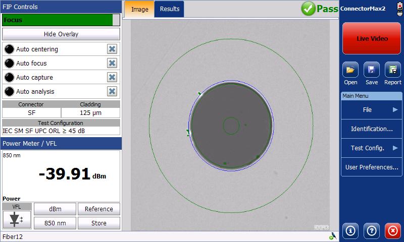
18 Introducing the FIP-400B Series Fiber Inspection Probe and ConnectorMax2 ConnectorMax2 Software ConnectorMax2 Software ConnectorMax2 is the application used to view the fiber inspections. You can also use specific test configurations and analyze the fibers automatically upon capturing a picture. This application is available on the MAX-FIP Viewer. All platforms except FTB-200v2 Focus indicator Image, Results, and Power Meter tabs Global status (Power meter and current connector (SF) or all fibers (MF)) Features Test configuration Capture/Live mode button Button bar Power meter controls and results/vfl Viewing area Probe connection status and connection mode (USB or Wi-Fi) 8 FIP-400B Series
 or all fibers (MF)) Features Capture/Live mode button Test configuration Button bar Power meter controls and results/vfl Shows or hides the FIP control panel Viewing area Probe")
19 Introducing the FIP-400B Series Fiber Inspection Probe and ConnectorMax2 Technical Specifications FTB-200v2 only Focus indicator Image, Results, and Power Meter tabs Global status (Power meter and current connector (SF) or all fibers (MF)) Features Capture/Live mode button Test configuration Button bar Power meter controls and results/vfl Shows or hides the FIP control panel Viewing area Probe connection status Technical Specifications To obtain this product s technical specifications, visit the EXFO Web site at Fiber Inspection Probe 9

20 Introducing the FIP-400B Series Fiber Inspection Probe and ConnectorMax2 Conventions Conventions Before using the product described in this guide, you should understand the following conventions: WARNING Indicates a potentially hazardous situation which, if not avoided, could result in death or serious injury. Do not proceed unless you understand and meet the required conditions. CAUTION Indicates a potentially hazardous situation which, if not avoided, may result in minor or moderate injury. Do not proceed unless you understand and meet the required conditions. CAUTION Indicates a potentially hazardous situation which, if not avoided, may result in component damage. Do not proceed unless you understand and meet the required conditions. IMPORTANT Refers to information about this product you should not overlook. Note: The appearance of the application may vary for other operating systems and units. Note: In this documentation, the words tap and double-tap (related to the use of a touchscreen) replace the words click and double-click. 10 FIP-400B Series

21 2 Safety Information WARNING Do not install or terminate fibers while a light source is active. Never look directly into a live fiber and ensure that your eyes are protected at all times. WARNING The use of controls, adjustments and procedures, namely for operation and maintenance, other than those specified herein may result in hazardous radiation exposure or impair the protection provided by this unit. IMPORTANT When you see the following symbol on your unit, make sure that you refer to the instructions provided in your user documentation. Ensure that you understand and meet the required conditions before using your product. IMPORTANT Other safety instructions relevant for your product are located throughout this documentation, depending on the action to perform. Make sure to read them carefully when they apply to your situation. CAUTION Do not use the fiber probe outdoors in wet locations. Fiber Inspection Probe 11


22 Safety Information Other Safety Symbols on Your Unit Other Safety Symbols on Your Unit One or more of the following symbols may also appear on your unit. Symbol Direct current Alternating current Meaning The unit is equipped with an earth (ground) terminal. The unit is equipped with a protective conductor terminal. The unit is equipped with a frame or chassis terminal. On (Power) Off (Power) OR On/Off (Power) Fuse 12 FIP-400B Series
23 Safety Information Electrical Safety Information Electrical Safety Information If you need to ensure that the unit is completely turned off, disconnect the power cable and remove the battery. WARNING Use the external electrical power supply indoors only. Position the unit so that the air can circulate freely around it. Operation of any electrical instrument around flammable gases or fumes constitutes a major safety hazard. To avoid electrical shock, do not operate the unit if any part of the outer surface (covers, panels, etc.) is damaged. Only authorized personnel should carry out adjustments, maintenance or repair of opened units under voltage. A person qualified in first aid must also be present. Do not replace any components while the power cable and battery are connected. Capacitors inside the unit may be charged even if the unit has been disconnected from its electrical supply. Use only the listed and certified AC adapter/charger provided by EXFO with your unit. It provides reinforced insulation between primary and secondary, and is suitably rated for the country where the unit is sold. Fiber Inspection Probe 13
24 Safety Information Electrical Safety Information Equipment Ratings for FIP-410B/FIP-420B/FIP-430B Temperature Operation Storage Relative humidity Maximum operation altitude Pollution degree Overvoltage category Equipment Ratings -10 C to 50 C (14 F to 122 F) -40 C to 70 C (-40 F to 158 F) 0 % to 95 % non-condensing 2000 m (6562 ft) 3 a I a. Equipment should be normally protected against exposure to direct sunlight, precipitations and full wind pressure. 14 FIP-400B Series
25 Safety Information Electrical Safety Information Equipment Ratings for FIP-425B/FIP-435B Temperature Operation Equipment Ratings Unit powered by batteries: -10 C to 40 C (14 F to 104 F) Unit connected to USB adapter: 0 C to 40 C (32 F to 104 F) Storage Unit without batteries: -40 C to 70 C (-40 F to 158 F) Unit with batteries: -20 C to 60 C (-4 F to 140 F) Relative humidity a unit: 95 % non-condensing USB adapter: 5 % to 95 % for storage and 8 % to 90 % for operating temperature Maximum operation altitude 2000 m (6562 ft) (unit connected to USB adapter) 3000 m (9843 ft) (unit operated from batteries) Pollution degree 2 (unit connected to external power supply) 3 (unit operated from batteries) b Overvoltage category unit: I AC adapter: II Measurement category Not rated for measurement categories II, III, or IV Input power c unit: 5 VDC; 1.8 A USB adapter: Vac; 50 Hz to 60 Hz; 0.4 A Max a. Measured in 0 C to 31 C (32 F to 87.8 F) range, decreasing linearly to 50 % at 40 C (104 F). b. Equipment must be normally protected against exposure to direct sunlight, precipitation and full wind pressure. c. Not exceeding ± 10 % of the nominal voltage. Fiber Inspection Probe 15
26
27 3 Setting up Your Fiber Inspection Probe and ConnectorMax2 You can change various settings in ConnectorMax2, such as the default storage location or the automated file name. These settings are stored for each user and kept for future work sessions. Connecting or Disconnecting the Wireless Probe IMPORTANT Working with a wireless probe is not possible on FTB-200v2 and IQS platforms. On supported platforms, the Wi-Fi option must be installed and the wireless communication must be enabled if you want to work with a wireless probe. For more information, refer to the corresponding user guide. The probes are identified by their serial numbers and type. It is also possible to disconnect the probe if you want to perform the following: Work with another probe Work with another platform Note: Once a connection has been established with a wireless probe, the latter remains connected as long as you do not disconnect it. However, when the application is in standby mode, the connection is lost. The application will try to reconnect automatically when the image reappears on screen. Fiber Inspection Probe 17

28 Setting up Your Fiber Inspection Probe and ConnectorMax2 Connecting or Disconnecting the Wireless Probe To connect the wireless probe: 1. Turn on the probe by pressing the ON button. 2. Ensure the Wi-Fi is activated on your platform. 3. Start the ConnectorMax2 application. 4. Select the wireless probe you want to work with and tap Connect. Note: The probes are identified by their serial numbers and types. 18 FIP-400B Series
 2. Select Disconnect. Fiber Inspection Probe 19")
29 Setting up Your Fiber Inspection Probe and ConnectorMax2 Connecting or Disconnecting the Wireless Probe To disconnect the wireless probe: 1. From the main window, tap. Battery status (appears only when a probe is connected by Wi-Fi) 2. Select Disconnect. Fiber Inspection Probe 19


30 Setting up Your Fiber Inspection Probe and ConnectorMax2 Changing the Fiber Inspection Probe Tip Changing the Fiber Inspection Probe Tip You can use various tips depending on the type of connector you are inspecting. For more information about tips you can use, see the Fiber Inspection Probe Tip Compatibility Chart on page 107, or contact your vendor for additional information. To change a tip: 1. Untighten the tip s retaining nut. 2. Remove the tip. 3. Insert a new tip. 4. Adjust the tip to the notch. 5. Retighten the retaining nut. 20 FIP-400B Series

31 Setting up Your Fiber Inspection Probe and ConnectorMax2 Adjusting Brightness Adjusting Brightness Once the probe is connected to a fiber, you can adjust brightness in order to better view the fiber under inspection. The default brightness value is 50 %. This corresponds to the automatic brightness mode. The brightness automatically returns to 50 %: when you exit the application and the probe is still connected when the application is open and you plug and unplug the probe when the platform is in suspend or resume mode when you lock or unlock a session (except on a MAX-700B) when you log in or log out of a session (except on a MAX-700B) To adjust brightness: 1. In Live video mode, tap the button to switch to video settings mode. Brightness button Fiber Inspection Probe 21

32 Setting up Your Fiber Inspection Probe and ConnectorMax2 Adjusting Brightness 2. Use the brightness slider to set the levels to suit your needs. Note: The application returns to the FIP controls default mode after 10 seconds of inactivity. Note: To optimize the analysis of the connector, EXFO recommends to set the brightness to Auto most of the time. When the brightness level is different than 50 %, the Automatic button appears. Tapping on the Automatic button resets the brightness value to 50 %. The Automatic button disappears when the brightness level equals 50 %. 22 FIP-400B Series
33 Setting up Your Fiber Inspection Probe and ConnectorMax2 Setting up Autonaming Setting up Autonaming The autonaming feature is useful to make a relevant naming scheme for your tests. This also ensures that you do not overwrite files by mistake. You can select which item goes in the file name (appears at the bottom of the window), as well as the type of separator you want to use in between. A preview is available to show you the final output of the file name. The file name is made of one or more static parts (alphanumeric) and one or more variable parts (numeric) that will be incremented or decremented, according to your selection, as follows: If you choose incrementation... Variable part increases until it reaches the highest possible value with the selected number of digits, then restarts at 1. If you choose decrementation... Variable part decreases until it reaches 1, then restarts at the highest possible value with the selected number of digits. Note: To decrement values, the start number must be higher than the stop number. The file name can be incremented using one or more identifiers. Selecting a single identifier will follow the incrementation (or decrementation) value you have set. Fiber Inspection Probe 23
34 Setting up Your Fiber Inspection Probe and ConnectorMax2 Setting up Autonaming For single fibers (SF or Transceivers), when selecting more than one identifier, the latter appear sequentially in the order that you have set, and the incrementation will start with the last item in the list (the one with the farthest indentation). For example, if you have a file name with the Location, Cable and Fiber identifiers, in that order, the first item to be incremented is the Fiber identifier, then Cable, then Location: Location 1, Cable 1, Fiber 1 Location 1, Cable 1, Fiber 2 Location 1, Cable 2, Fiber 1 Location 1, Cable 2, Fiber 2 and so forth. For multifibers, when several identifiers for the filename are selected, they appear sequentially in the order you have set. However, only one increment can be used to create a multifiber set of captures. If several increments are selected, only the most indented identifier will be used as the increment. If no auto increment is defined, the identifier Frame is used (whether or not it is selected for the file name). After a result is saved, you have to return to the Live video mode so that the application prepares the next file name by incrementing (or decrementing) the suffix. Note: If you choose not to save a particular file, the suggested file name remains available for the next capture. This applies to all type of connectors. 24 FIP-400B Series
35 Setting up Your Fiber Inspection Probe and ConnectorMax2 Setting up Autonaming This function is particularly useful when testing multiple-fiber cables. If you deactivate the automatic file naming function, the application displays a Save As window and no default file name is suggested. The autonaming parameters can be set only for files that have not been saved yet. You will only see the parameters for the current and next capture (when the test is done but not saved yet), or for the next capture only (test is not done yet). Otherwise, the parameters will not be displayed. It is also possible to revert the settings to their default values. To configure the automatic file naming: 1. From the Main Menu, tap Identification. Fiber Inspection Probe 25
36 Setting up Your Fiber Inspection Probe and ConnectorMax2 Setting up Autonaming 2. From the Apply to list, ensure that Next capture or Current and Next capture is selected. 3. Enter all the information as follows: 3a. Locate the row corresponding to the identifier that you want to modify. If an identifier is marked with an icon, a predefined list with choices is available. If you select None, it disables the field from the list (Next capture and Current and Next capture). Note: When in Current capture, the identifiers set to None disappear from the list. Note: The identifiers marked with an icon are fields that can be customized and edited. The name of the identifier and its value can be modified. 3b. Tap the Value column corresponding to the desired identifier. 3c. Enter the information. Note: You cannot edit the information in the dark gray boxes. 26 FIP-400B Series
37 Setting up Your Fiber Inspection Probe and ConnectorMax2 Setting up Autonaming 4. If you want to increment automatically the cable ID, the fiber ID, the location (A and/or B), the Connector ID, or the Frame, proceed as follows: 4a. Tap the Increment button. 4b. In the Increment window, select the Auto Increment check box corresponding to the identifier you want to increment. Fiber Inspection Probe 27

38 Setting up Your Fiber Inspection Probe and ConnectorMax2 Setting up Autonaming 4c. Enter the start, stop and increment values as desired. Note: The identifiers are processed in order, from the one with the largest indentation to the one with the smallest. For a given identifier, when the increment value reaches the stop value, the incrementation automatically switches to the next identifier. The order of the identifiers in the increment window (and thereby the order of increment) follows the order of the identification window. Note: An identifier set to None will not appear in the increment window. Note: To decrement values, the start number must be higher than the stop number. 4d. Tap OK to return to the Identification window. 28 FIP-400B Series
39 Setting up Your Fiber Inspection Probe and ConnectorMax2 Setting up Autonaming 5. Select the desired identifiers to include in the file name. You can change the order of appearance of the highlighted component with the up and down arrow buttons. Items that can be included in the file name To modify the order of appearance of the selected identifiers in the file name This preview is updated automatically as you make your selections To select the separator in the automatic numbering section 6. Tap OK to confirm your new settings and to return to the main window. The new settings will apply the next time you perform a capture. Fiber Inspection Probe 29
40 Setting up Your Fiber Inspection Probe and ConnectorMax2 Setting up Autonaming To clear the values: 1. From the Main Menu, tap Identification. 2. In the Apply to list, select Next capture. 3. Tap the Clear Values button. 4. Tap OK to return to the main window. All values in the Value column are erased from the white boxes. 30 FIP-400B Series
41 Setting up Your Fiber Inspection Probe and ConnectorMax2 Managing and Selecting Test Configurations Managing and Selecting Test Configurations You can create and select specific test configurations according to the type of fiber you are analyzing, the connector type you are using or the type of anomaly you are looking for. Note: If you have the FIP-420B or FIP-430B probe, some test configurations as per IEC and IPC standards, and other configurations with an enlarged adhesive C zone are available by default. Creating custom test configurations is done through duplicating an existing configuration, and then modifying the desired criteria. If you create configurations on one unit or computer, and want to transfer them to another unit or computer, you can do so. To select a test configuration: 1. From the Main Menu, select Test Config. Fiber Inspection Probe 31
42 Setting up Your Fiber Inspection Probe and ConnectorMax2 Managing and Selecting Test Configurations 2. Select FIP. 3. If necessary, in the Apply to list, select Next capture. 4. Choose the type of connector you want to use and tap the button at the end of the row. 32 FIP-400B Series

43 Setting up Your Fiber Inspection Probe and ConnectorMax2 Managing and Selecting Test Configurations 5. In the list of available test configurations, select the configuration you want to use and tap OK. To create a test configuration: 1. From the Main Menu, select Test Config. Fiber Inspection Probe 33
44 Setting up Your Fiber Inspection Probe and ConnectorMax2 Managing and Selecting Test Configurations 2. Select FIP. 3. If necessary, in the Apply to list, select Next capture. 4. Choose the type of connector you want to use and tap the button at the end of the row. 34 FIP-400B Series

45 Setting up Your Fiber Inspection Probe and ConnectorMax2 Managing and Selecting Test Configurations 5. Select the row corresponding to the configuration that is the closest to the one you want to create, then tap Duplicate. 6. If you want to modify the general information, proceed as follows: 6a. In the Configuration Details window, tap the button at the end of the Properties row. 6b. Modify the parameters as needed. Configuration name: the application suggests a name for the configuration. You can change it as needed (maximum 256 characters), but if you select a name that already exists, a suffix will automatically be added so as not to overwrite files. Connector type: Select which type of connector you are using for your inspection. Fiber type: Select whether you are inspecting singlemode or multimode fibers. Polishing type: Select the type of polishing for the fibers between APC, PC or UPC. Fiber Inspection Probe 35

46 Setting up Your Fiber Inspection Probe and ConnectorMax2 Managing and Selecting Test Configurations Analysis mode: Select the type of analysis between Outside plant (selected by default) and Manufacturing. The manufacturing mode is more sensitive for scratches and defects detection. Cladding diameter: This value is set at 125 μm by default. Zone diameters: You can change the zone dimension for single fiber connectors and Transceiver fiber receptacles. Note: Zone C (adhesive) cannot be removed and the superior diameter of zone D cannot exceed 280 μm. Note: When a multifiber connector is selected, zone D is not available. Note: When you duplicate and edit a test configuration, you cannot change the connector type field. 6c. Tap OK to confirm your choice and close the window. OR Use the Config. Details arrow to go back to the Configuration Details window and configure other parameters. 36 FIP-400B Series

47 Setting up Your Fiber Inspection Probe and ConnectorMax2 Managing and Selecting Test Configurations 7. If you want to modify the information about the inspection zones, proceed as follows: 7a. Tap the button corresponding to the desired inspection zones. 7b. Modify the parameters as needed to indicate whether you want to be notified of scratches, defects or both for each zone in the fiber, then set thresholds for each item you select. You can set up to 3 criteria per zone, and per anomaly type (scratches or defects). The thresholds are divided into three categories: Any: this enables the next criterion, which requires a specific value. 1 to 10: the next criterion is automatically filled out to show the infinity symbol ( ) and 0 as a threshold. 0: the criterion definition is complete. Note: Zone C, as well as zone dimensions cannot be modified, as they are set as per IEC and IPC recommendations. Fiber Inspection Probe 37
48 Setting up Your Fiber Inspection Probe and ConnectorMax2 Managing and Selecting Test Configurations 7c. Tap OK to confirm your choice and close the window. OR Use the Config. Details arrow to go back to the Configuration Details window and configure other parameters. 8. If necessary, use the Config. Details arrow to go back to the Configuration Details window and tap OK to close the window. OR Use the FIP Config. arrow to go back to the FIP configuration list. 38 FIP-400B Series
49 Setting up Your Fiber Inspection Probe and ConnectorMax2 Managing and Selecting Test Configurations To edit a test configuration: 1. From the Main Menu, select Test Config. 2. Select FIP. Fiber Inspection Probe 39

50 Setting up Your Fiber Inspection Probe and ConnectorMax2 Managing and Selecting Test Configurations 3. If necessary, in the Apply to list, select Next capture. 4. Choose the type of connector you want to use and tap the button at the end of the row. 5. Select the configuration you want to edit and tap the button at the end of the row. Note: You cannot edit standard test configurations. 6. Change the criteria as required. For details, see the section on creating a test configuration. 40 FIP-400B Series
51 Setting up Your Fiber Inspection Probe and ConnectorMax2 Managing and Selecting Test Configurations To delete a test configuration: 1. From the Main Menu, select Test Config. 2. Select FIP. Fiber Inspection Probe 41
52 Setting up Your Fiber Inspection Probe and ConnectorMax2 Managing and Selecting Test Configurations 3. If necessary, in the Apply to list, select Next capture. 4. Choose the type of connector you want to use and tap the button at the end of the row. IMPORTANT The application will not prompt you for confirmation before deleting a configuration. 42 FIP-400B Series

53 Setting up Your Fiber Inspection Probe and ConnectorMax2 Managing and Selecting Test Configurations 5. Select the row corresponding to the configuration you want to remove, then tap Delete. Note: You cannot delete standard test configurations. Fiber Inspection Probe 43
54 Setting up Your Fiber Inspection Probe and ConnectorMax2 Managing and Selecting Test Configurations To import test configurations: 1. From the Main Menu, select Test Config. 2. Select FIP. 44 FIP-400B Series
55 Setting up Your Fiber Inspection Probe and ConnectorMax2 Managing and Selecting Test Configurations 3. Choose the type of connector you want to use and tap the button at the end of the row. 4. From the FIP Configuration window, tap Import. Fiber Inspection Probe 45

56 Setting up Your Fiber Inspection Probe and ConnectorMax2 Managing and Selecting Test Configurations 5. From the Open dialog box, select the file you want to import. 6. Tap OK to close the window. 46 FIP-400B Series
57 Setting up Your Fiber Inspection Probe and ConnectorMax2 Managing and Selecting Test Configurations To export test configurations: 1. From the Main Menu, select Test Config. 2. Select FIP. Fiber Inspection Probe 47

58 Setting up Your Fiber Inspection Probe and ConnectorMax2 Managing and Selecting Test Configurations 3. Choose the type of connector you want to use and tap the button at the end of the row. 4. From the FIP Configuration window, select the row corresponding to the test configuration you want to export. Note: You cannot export standard test configurations. 5. Tap Export. 48 FIP-400B Series

59 Setting up Your Fiber Inspection Probe and ConnectorMax2 Managing and Selecting Test Configurations 6. From the Save As dialog box, select the folder where you want to export your file. 7. If desired, modify the file name. 8. Tap OK to close the window. Fiber Inspection Probe 49
60 Setting up Your Fiber Inspection Probe and ConnectorMax2 Editing the Power Meter Test Configurations Editing the Power Meter Test Configurations You can activate and set pass/fail threshold parameters for your power meter measurements. You can set thresholds for absolute power and insertion loss. You can set different pass/fail thresholds for each available test wavelength, or apply the same thresholds to all wavelengths. Values that are greater than the predefined thresholds are displayed in white on a red background. Values that are pass are displayed in green. To edit the power meter test configurations: 1. From the Main Menu, select Test Config. 50 FIP-400B Series
61 Setting up Your Fiber Inspection Probe and ConnectorMax2 Editing the Power Meter Test Configurations 2. Select Power Meter. 3. In the Apply to list, select Next capture. 4. Select the desired wavelength. 5. Set the pass/fail thresholds for the selected wavelength. Note: You can apply the settings to all wavelengths. Fiber Inspection Probe 51
62 Setting up Your Fiber Inspection Probe and ConnectorMax2 Reverting to Factory Settings 6. Choose the absolute power units. 7. If you want to see the pass/fail status, check the Apply thresholds (Pass/Fail status) option. Reverting to Factory Settings At any time in the application, you can revert to factory settings in your menus. However, the Restore to Factory Settings button is valid only for the window or tab where you use it. 52 FIP-400B Series

63 Setting up Your Fiber Inspection Probe and ConnectorMax2 Changing Fiber Information of Existing Captures Changing Fiber Information of Existing Captures It is possible to modify the information for an existing capture. This information is provided by the automatic file naming. The procedure is almost the same as the one for autonaming but the changes apply to the current capture only. To change fiber information: 1. From the Main Menu, tap Identification. 2. From the Apply to list, ensure that Current capture is selected. 3. Set the parameters as needed. For more information, see Setting up Autonaming on page 23. Fiber Inspection Probe 53
64
65 4 Inspecting Fiber Ends Viewing the fiber inspection is done using ConnectorMax2. You can start the application before or after connecting the probe, and the view on-screen will be automatically updated. WARNING Never look directly into a live fiber. It could cause serious eye damage. Always use your FIP-400B Series Fiber Inspection Probe. Inspecting Fiber Ends (Single Fiber and Transceiver - Fiber Receptacles) When you connect the FIP-400B Series Fiber Inspection Probe to your unit, you can view and inspect fiber ends right away. This direct viewing mode is known as the Live Video mode. Since the available controls depend on the probe that is connected, if you disconnect the probe, the application will show an empty window. The controls become available again as soon as you reconnect the probe (no need to restart the application). Note: When the internal temperature of the FIP-430B and FIP-435B is too low, the probe performs a warm-up that can last up to a minute. You can also capture images of your inspections to include in reports, or save them for future analyses. This is known as the Capture mode. Note: A digital watermark is added to the images generated by the application. This also applies to ConnectorMax1 files converted to the ConnectorMax2 format. Fiber Inspection Probe 55
66 Inspecting Fiber Ends Inspecting Fiber Ends (Single Fiber and Transceiver - Fiber Receptacles) The focus indicator, which is displayed in the upper left part of the main window, indicates whether the current view is optimized for a capture. A green indicator shows a picture that can be captured and analyzed. Analysis will be more difficult with a yellow indicator, and impossible with a red indicator. A vertical black bar displays the peak focus level. Note: The peak focus level is shown only when the auto focus sequence is complete. For more information on analysis, see Analyzing Captures on page 74. To inspect fiber ends (single fiber) in Live mode: 1. Install a probe tip (see Changing the Fiber Inspection Probe Tip on page 20). 2. Insert the fiber into the probe tip. 3. Connect your Fiber Inspection Probe to a computer or your unit. On an FTB-500, connect the probe to the lower USB port located on the front of the unit. 56 FIP-400B Series
67 Inspecting Fiber Ends Inspecting Fiber Ends (Single Fiber and Transceiver - Fiber Receptacles) 4. Start ConnectorMax2 if it is not already started. 5. Ensure to configure the automatic file naming (see Setting up Autonaming on page 23). 6. Choose whether you are using an SF or Transceiver connector. 7. Choose the type of connector you want to use between Standard, LC APC, or E2000. Fiber Inspection Probe 57
68 Inspecting Fiber Ends Inspecting Fiber Ends (Single Fiber and Transceiver - Fiber Receptacles) 8. Depending on the probe you are using, proceed as follows: If you have an FIP-420B, activate the auto centering, then adjust the magnification level and the image focus to have the best view of the fiber end. If you have an FIP-430B, activate the auto centering and the auto focus. For more information, see Analyzing Captures on page If the fiber end is dirty, remove it from the probe, clean it and reinspect it. 10. Once you are satisfied with the inspection, when in high magnification level, press Capture. OR Press the Fiber Inspection Probe handset button. 11. Go to the next connector or close the application. 58 FIP-400B Series

69 Inspecting Fiber Ends Setting Up Multifiber Inspection Setting Up Multifiber Inspection Inspecting and analyzing multifiber connectors can be done separately for each fiber, or as a batch. When the inspection and the analysis are done separately, there is a transition between the Live Video mode and the Capture mode after an image is captured. To speed up the process of inspecting and analyzing connectors and fibers, you can use the batch inspection feature. With this feature, all fibers are captured and previewed one after the other for a configured period of time. Then the analysis is launched when all fibers are inspected. To use the batch inspection and analysis process: 1. From the main window, select User Preferences. 2. Select the MF Connector tab. 3. Choose Use batch inspection or analysis process (applies to the next capture). This enables the preview duration time box. 4. Enter the time you want the preview to last. 5. Tap OK to confirm your choice and close the window. Fiber Inspection Probe 59
70 Inspecting Fiber Ends Displaying Multifiber Connector Overlay Displaying Multifiber Connector Overlay By default, ConnectorMax2 displays the multifiber overlay only in high magnification. The overlay is used to see which of the connectors in a multifiber connector is being inspected. It is possible to see four fibers at a time when the overlay is displayed. Note: The FIP-410B probe does not display the overlay in multifiber. To display the multifiber connector overlay: 1. From the main window, select User Preferences. 2. Select the MF Connector tab. 3. Choose Include multifiber connector overlay. 4. Tap OK to confirm your choice and close the window. 60 FIP-400B Series
71 Inspecting Fiber Ends Inspecting Fiber Ends (Multifiber) In the main window, a blue arrow now indicates the fiber under test. Inspecting Fiber Ends (Multifiber) The multifiber inspection with a FIP-430B probe allows you to see multiple fibers at a time. You can also capture images of your inspections to include in reports, or save them for future analyses. This is known as the Capture mode. A digital watermark is added to the images generated by the application. This also applies to ConnectorMax1 files converted to the ConnectorMax2 format. Fiber Inspection Probe 61

72 Inspecting Fiber Ends Inspecting Fiber Ends (Multifiber) The focus indicator, which is displayed in the upper left part of the main window, indicates whether the current view is optimized for a capture. A green indicator shows a picture that can be captured and analyzed. Analysis will be more difficult with a yellow indicator, and impossible with a red indicator. A vertical black bar displays the peak focus level. Note: The peak focus level is shown only when the auto focus sequence is complete. To speed up the process of inspecting and analyzing connectors and fibers, you can use the batch inspection feature. With this feature, all fibers are captured and previewed one after another for a configured period of time. Then the analysis is launched when all fibers are inspected. For more information on analysis, see Analyzing Captures on page FIP-400B Series
73 Inspecting Fiber Ends Inspecting Fiber Ends (Multifiber) To inspect fiber ends (multifiber) in Live mode: 1. Install a probe tip (see Changing the Fiber Inspection Probe Tip on page 20). 2. Insert the fiber into the probe tip. 3. Insert replaceable APC or UPC nozzle in and tighten it (turn clockwise). 4. For patchcord inspection, insert a mating tip. 5. Connect your Fiber Inspection Probe to a computer or your unit. On an FTB-500, connect the probe to the lower USB port located on the front of the unit. Fiber Inspection Probe 63
74 Inspecting Fiber Ends Inspecting Fiber Ends (Multifiber) 6. Start ConnectorMax2 if it is not already started. 7. Ensure to configure the automatic file naming (see Setting up Autonaming on page 23). 8. Choose MF. OR Tap File, then New. 64 FIP-400B Series
75 Inspecting Fiber Ends Inspecting Fiber Ends (Multifiber) 9. Choose the type of connector you want to use between MPO/MTP (selected by default) or OptiTip. 10. Depending on the probe you are using, proceed as follows: If you have an FIP-420B, activate the auto centering. If you have an FIP-430B, activate the auto centering and the auto focus. For more information, see Analyzing Captures on page Set the probe to Low Magnification and locate the first fiber. Fiber Inspection Probe 65

76 Inspecting Fiber Ends Inspecting Fiber Ends (Multifiber) 12. Set the probe to High Magnification. Note: The FIP-420B and FIP-430B probes show a low magnification connector image in the overlay. 13. Center the appropriate connector in the array: For multi-row tips, use the Y wheel to select the required fiber row. For multi-row and single-row tips, use the X wheel to select the required fiber. X wheel Y wheel 66 FIP-400B Series
. OR Adjust focus manually. 15.")
77 Inspecting Fiber Ends Inspecting Fiber Ends (Multifiber) 14. View results on screen. Note: The auto focus starts automatically only for the first fiber (FIP-430B only). Hold the magnification control button located on the probe for one second to reactivate the auto focus process (FIP-430B only). OR Adjust focus manually. 15. If the fiber end is dirty, remove it from the probe, clean it and reinspect it. 16. When in high magnification level, press Capture. OR Press the Fiber Inspection Probe handset button. 17. If you are not using the batch inspection feature, return to Live Video mode. Repeat steps 13 to 17 until you reach the end of the connector. 18. If you are using the batch inspection feature, press Process. OR To continue the current connector inspection, return to Live Video mode. 19. To inspect a new connector, tap File, then New. Fiber Inspection Probe 67

78 Inspecting Fiber Ends Retesting a Fiber (Multifiber) Retesting a Fiber (Multifiber) Sometimes, a capture will show a fail status, but it could only be because the fiber is dirty and you want to clean it and test it again. However, if you have saved the file, the next capture you take will be incremented instead of replacing the current file. In order to avoid this incrementation and end up with unwanted files, you can test a fiber again. To retest a fiber in Live Video mode: 1. Use the list to navigate between the captured fibers. 2. Tap Capture. 68 FIP-400B Series

79 Inspecting Fiber Ends Retesting a Fiber (Multifiber) To retest a fiber in Capture mode: 1. Use the list to navigate between the captured fibers. To minimize or maximize the navigation toolbar To retest a fiber Pass/Fail status for current SF and power meter To view next fiber To view previous fiber 2. Tap Reset. Fiber Inspection Probe 69
80 Inspecting Fiber Ends Saving Files Saving Files In Capture mode, you can save the acquisition files manually for future reference. You can also set ConnectorMax2 so that it saves the capture automatically only if the result is Pass, or regardless of the status. Note: Saving a file automatically after a capture is not possible in multifiber mode. Note: When you return to the Live Video mode, your file name structure will be automatically incremented or decremented so that you do not overwrite your work. To save files automatically, or automatically only when the status is set to Pass: 1. From the main window, select User Preferences. 70 FIP-400B Series
81 Inspecting Fiber Ends Saving Files 2. Select the General tab. 3. Select whether you want the capture to be automatically saved regardless of the result (all models), saved if the result of the analysis is pass (only available with the FIP-420B and FIP-430B models), or select the manual save option if you only want to save specific files. 4. If you want to change the default location where the files will be saved, you can do so by using the button. 5. Tap OK to confirm your choice. Fiber Inspection Probe 71
82 Inspecting Fiber Ends Saving Files To save a file: From the main window, tap the button. OR Select the File menu, then Save to overwrite an existing file. OR Select the File menu, then Save As to change the file name or location. Note: If you change the location for saving the files, this location will remain as the default location for the remainder of the work session, or until you change the location again. IMPORTANT If you have enabled the Generate report on save option, the new report file will automatically overwrite the old one without notifying you. 72 FIP-400B Series
83 Inspecting Fiber Ends Opening and Closing Files Opening and Closing Files You can open captured files directly from the application to view them. You can either open current.cmax2 files,.cmax files (not supported by MAX-700B and MAX-FIP), or a legacy image file taken from a previous fiber inspection. The.cmax files, when saved with the ConnectorMax 2 application, are compatible with any EXFO applications. However, the.cmax2 files can be opened with the ConnectorMax 2 application only. Note: The accepted image formats for legacy files are.bmp,.jpg and.gif. Note: Sample files are available on the platform. To open a file: 1. From the main window, select File, and then Open. 2. Select the desired file, and then tap OK. Fiber Inspection Probe 73
84 Inspecting Fiber Ends Analyzing Captures Analyzing Captures With the capture analysis option (FIP-420B/FIP-425B and FIP-430B/FIP-435B), you can perform automated pass/fail analyses according to the criteria you have set. Note: Analysis is not available for the FIP-410B. Depending on the fiber probe that you have, you may have access to the following features: Auto centering: displays the fiber in the middle of the image. It is compatible with all connector types and fibers with a cladding of 125 μm. The auto centering is enabled only in high magnification. Working with the auto centering feature can be useful with standard connectors. When inspecting special connectors, it is also possible to uncheck the auto centering check box. Auto focus: focuses on the connector image. It is enabled if the auto centering is activated and only in high magnification. The auto focus is only possible in Live Video mode, and if the focus is not done manually. It starts automatically when you insert an optical fiber connector. For more information, see Fiber Inspection Probe Tip Compatibility Chart on page 107. Auto capture: is possible with an acceptable focus level. It is enabled if the auto centering and auto focus are activated. The auto capture is possible only in high magnification. For the FIP-430B probe, the auto capture is not displayed when a multifiber connector is selected. Auto analysis: displays 4 inspection zones: core, cladding, adhesive, and contact. It is enabled only in high magnification and with a good focus. When a multifiber connector is selected, the auto analysis is available for zone A and B only. 74 FIP-400B Series
85 Inspecting Fiber Ends Analyzing Captures An indicator is located at the left of the available features. The color of this indicator shows the status of the feature: Grey Green Color Meaning The item is not selected The item is selected and the conditions allow the analysis. Black The item is selected but the conditions do not allow the analysis. The auto focus process was aborted by the user. Red The application is in timeout state because it is unable to complete the auto focus process. There are three ways to reapply the auto focus: Clear the auto focus check box and select it again Press the FIP-400B Series magnification button for 1second From Capture mode, return to Live video mode Fiber Inspection Probe 75

.")
86 Inspecting Fiber Ends Analyzing Captures To select the analysis features: Select the features you need for the capture. The analysis results are available as soon as you tap Process or when you press the capture button on the probe. Fibers are analyzed sequentially. The process time depends on the number of fibers to be analyzed. The global status is displayed in the upper right part of the window after an analysis.the Image and Results tabs are displayed when a capture is made (using the button from the button bar or on the probe). When you are ready to inspect another fiber, you have to return to the Live Video mode first. To disable the analysis features: Clear the check box next to the corresponding features. The results are available as an image or in a detailed table. 76 FIP-400B Series
 found on the fiber endface.")

87 Inspecting Fiber Ends Analyzing Captures The Image tab shows the snapshot of the fiber when you captured it. You can see all the anomalies that have been detected. The overlay shows the status of the analysis, the status per zone, the analysis zones, any anomaly (defects, scratches) found on the fiber endface. The color of the circles shows the status of the analysis zone: Green: pass Blue: no analysis was performed or the function is disabled Red: fail Note: You can change the diameter of the analysis zones. For more information, see Managing and Selecting Test Configurations on page 31. By default, the overlay is shown after an analysis, but you can hide it using the Hide Overlay button. Fiber Inspection Probe 77

88 Inspecting Fiber Ends Analyzing Captures The Results tab shows detailed information for scratches and defects detected in each test zone and the corresponding test status. Note: When there is no analysis, the Results tab does not appear. 78 FIP-400B Series
89 Inspecting Fiber Ends Displaying or Hiding the Power Meter and VFL Controls Displaying or Hiding the Power Meter and VFL Controls By default, the power meter and VFL controls are displayed in the left side bar of the main window. However, you can hide them. This option is present on all platforms even if no power meter or VFL is available, except on computers. To display or hide the power meter and VFL controls: 1. From the main window, select User Preferences. 2. Select the General tab. 3. Under Display, select Display power meter/vfl controls. 4. Tap OK to confirm your choice and close the window. Fiber Inspection Probe 79
90 Inspecting Fiber Ends Clearing Power Meter Measurements Automatically Clearing Power Meter Measurements Automatically Measurements can be automatically erased from memory upon returning to the Live video mode. This option is present on all platforms even if no power meter is available, except on computers. To clear power meter measurements automatically: 1. From the main window, select User Preferences. 2. Select the General tab. 3. Under Stored Measurements, select Clear power meter measurements upon switching to live video. 4. Tap OK to confirm your choice and close the window. 80 FIP-400B Series
91 Inspecting Fiber Ends Measuring Power or Insertion Loss Measuring Power or Insertion Loss If your unit is equipped with a power meter, ConnectorMax2 provides power meter measurements. The power meter view displays current power and loss measurements. This view is available either in Live mode or Capture mode. For the MAX-700B platform, you can either perform measurements manually and select each wavelength yourself, or you can use the auto-wavelength and auto-switching modes of your source. Note: When there is a selected wavelength and the source is in Auto mode, the power meter switches automatically to Auto mode. The correction factors and the offset nulling are not supported by ConnectorMax2. For more information on your power meter, refer to the corresponding user guide. Fiber Inspection Probe 81
. The global pass/fail status also takes the power meter measurements into account. To view power or insertion loss measurements: Select the Power Meter tab.")
92 Inspecting Fiber Ends Viewing Power Meter Results Viewing Power Meter Results You can view the power meter results stored in memory in a separate tab (see Measuring Power or Insertion Loss on page 81). The global pass/fail status also takes the power meter measurements into account. To view power or insertion loss measurements: Select the Power Meter tab. All your measurements are displayed in the order they were performed. Switches between current measurement and stored measurement 82 FIP-400B Series
93 Inspecting Fiber Ends Identifying Fiber Faults Visually with the VFL Identifying Fiber Faults Visually with the VFL Your unit can be equipped with an optional visual fault locator (VFL) to help you identify bends, faulty connectors, splices and other causes of signal loss. It can also help the person at the other end of the link to identify the fiber under test, which could be particularly useful when working with cables containing many fibers. From its dedicated port, the VFL emits a red signal which becomes visible at the location of a fault on the fiber. This signal can be continuous (CW) or blinking (1 Hz). The VFL is available either in Live mode or Capture mode. It can be switched from one state to another (on, off or blink). WARNING When the VFL is active, the VFL port emits visible laser radiation. Avoid exposure and do not stare directly into the beam. Protect any unused port with a cap. Fiber Inspection Probe 83
94 Inspecting Fiber Ends Creating Reports Creating Reports You can create a report based on the current inspection and analysis results. This report can be saved in the following formats: PDF, HTML and MHTML. However, HTML and MHTML reports are not supported on the MAX-700B and MAX-FIP platforms. Note: The report creation is available only in Capture mode. Note: The report may include the OPM results or not. Even if there are no OPM results, the report title still mentions OPM results and the global pass/fail includes both FIP and OPM results. If you have selected the Generate report on save option, a report is automatically created when you save your capture. IMPORTANT Your application has been designed for optimal viewing of the fonts shown in reports in all supported languages. Ensure the language settings for Non-Unicode applications remains to English (United States). 84 FIP-400B Series

95 Inspecting Fiber Ends Creating Reports To activate automated report creation: 1. From the main window, select User Preferences. 2. Select the General tab. 3. Under File Functionalities, select Generate report on save. 4. Tap OK to confirm your choice and close the window. Fiber Inspection Probe 85
96 Inspecting Fiber Ends Creating Reports To create a report manually: 1. From the main window, tap. OR Select the File menu, then Report. 2. From the Save As dialog box, select a folder or create one to save your file. 86 FIP-400B Series
97 Inspecting Fiber Ends Updating the Firmware and Software 3. If desired, modify the file name. 4. Tap OK to close the window. You can now open the report with PDF reader from the location where the file was saved. The HTML and MHTML reports are compatible with Internet Explorer (IE 7 and latest), and the latest software release of FireFox and Google Chrome. Updating the Firmware and Software The FIP-400B Series is designed to provide automatic software update notifications and firmware updates whenever necessary. This allows you to benefit from the updates of your unit each time you use it. The firmware and software updates can be recommended or required. To notify you, a message box appears each time a firmware or software update is recommended. When a firmware update is required, the application shows an error if you choose not to update the FIP-400B Series. If a firmware update fails, ConnectorMax2 performs a fault recovery procedure the next time the FIP-400B Series is connected. The FIP-400B Series becomes unavailable if a software update is required or when a firmware update is in progress. The Live video button becomes disabled in capture view and in video view, the capture button becomes disabled as well. CAUTION Do not disconnect the probe or turn off the unit when an update is in progress. Fiber Inspection Probe 87
98 Inspecting Fiber Ends Updating the Firmware and Software Once an update is started, follow the indications to complete the process. IMPORTANT During the automatic upgrade of the firmware of your FIP-400B Series probe, you may be prompted to install USB drivers for your instrument. In that case, you need to map your fiber inspection probe with the necessary driver. To be notified of the firmware or software updates automatically: 1. From the main window, select User Preferences. 2. Select the General tab. 3. Under Display, choose the appropriate option. 4. Tap OK to confirm your choice and close the window. Note: By default, both check boxes are selected. 88 FIP-400B Series


99 Inspecting Fiber Ends Updating the Firmware and Software To configure the USB driver for your fiber inspection probe: 1. Confirm the firmware upgrade when ConnectorMax2 prompts you. 2. During the upgrade process, the Found New Hardware wizard can be displayed. In this case, if the application prompts you to connect to Windows Update to search for software, select No, not this time, and then click Next. 3. Make sure that the Install the software automatically (Recommended) option is selected, and click Next. Fiber Inspection Probe 89

100 Inspecting Fiber Ends Updating the Firmware and Software 4. The wizard may display a warning message indicating that the hardware has not passed Windows Logo testing. In this case, since it has been verified that the drivers work with Windows, click Continue Anyway. 5. Follow the on-screen instructions, and then click Finish when the installation is complete. 6. When the application displays an error message indicating that the FIP firmware update has failed, click OK to close the message. The automatic upgrade process will continue normally since the driver has been associated with your fiber inspection probe already. Note: If the application continues to display the firmware update error message even after the driver has been associated correctly with your fiber inspection probe, contact technical support. 90 FIP-400B Series
101 5 Maintenance General Maintenance To help ensure long, trouble-free operation: Always inspect fiber-optic connectors before using them and clean them if necessary. Keep the unit free of dust. Clean the unit casing with a cloth slightly dampened with water. Store unit at room temperature in a clean and dry area. Keep the unit out of direct sunlight. Avoid high humidity or significant temperature fluctuations. Avoid unnecessary shocks and vibrations. If any liquids are spilled on or into the unit, turn off the power immediately, disconnect from any external power source, remove the batteries and let the unit dry completely. WARNING The use of controls, adjustments and procedures, namely for operation and maintenance, other than those specified herein may result in hazardous radiation exposure or impair the protection provided by this unit. Recycling and Disposal (Applies to European Union Only) For complete recycling/disposal information as per European Directive WEEE 2012/19/UE, visit the EXFO Web site at Fiber Inspection Probe 91
102 Maintenance Recharging the Battery (FIP-425B and FIP-435 Models Only) Recharging the Battery (FIP-425B and FIP-435 Models Only) The battery in your Fiber Inspection Probe is a Li-ion polymer battery with three-cell format. The charge status is shown with the LEDs on the Fiber Inspection Probe. The ConnectorMax2 software application also indicates the charge status. CAUTION Only charge the battery with the USB cable and adapter/charger provided by EXFO with your unit. You can purchase a new battery from EXFO. IMPORTANT The battery is not charged at the factory. You must fully charge it before using the unit for the first time. The battery is fully charged after a few hours or when the battery LED indicator stops flashing. The charge cycle starts and stops automatically. The time required to charge the battery depends on various factors such as the ambient temperature. To ensure that the battery functions or charges properly, keep it within operation and storage temperature range. The micro USB adapter connector recharges the battery of the probe when it is low. You can recharge the battery with the provided USB cable and the adapter/charger that you connect to a power outlet. You can also use the provided USB cable alone that you connect to a USB port of a computer. When the probe is connected to a power outlet or to a USB port, it still works via Wi-Fi. It is possible to recharge the battery of the probe when it is connected to the USB port of a computer (500 ma). 92 FIP-400B Series
103 Maintenance Replacing the Battery (FIP-425B and FIP-435 Models Only) Replacing the Battery (FIP-425B and FIP-435 Models Only) Your probe is powered by a Li-ion polymer rechargeable battery. WARNING Your unit uses a three-cell battery that has been especially designed for EXFO. For this reason, you can only replace it with a battery of the same type and model. The use of other batteries may damage your unit and compromise your safety. Battery replacement should only be done by a qualified technician with the appropriate tools on an electronic bench or similar environment. Do not throw the battery into fire or water and do not short-circuit the battery electrical contacts. Do not disassemble. CAUTION To avoid irremediable damage to the battery, always remove the battery compartment door carefully, ensuring that the battery does not fall. Fiber Inspection Probe 93

104 Maintenance Replacing the Battery (FIP-425B and FIP-435 Models Only) To replace the battery: 1. Turn off the probe. 2. Unplug any power cable. 3. Using a screwdriver, remove the two screws that are located on the side of the probe. Screws Battery compartment door 4. Remove the battery compartment door. CAUTION Gently pull on the battery to avoid damaging the wires. 94 FIP-400B Series
105 Maintenance Replacing the Battery (FIP-425B and FIP-435 Models Only) 5. Remove the battery. Wires Battery 6. Replace the battery, respecting the polarity (black, yellow, and red wires). 7. Close the battery compartment door. 8. Using a screwdriver, put the screws that you have removed at step 3 back in place. Fiber Inspection Probe 95
106
107 6 Troubleshooting Solving Common Problems The table below presents common problems and their solutions. Problem I cannot analyze an image I cannot see the fiber on-screen The FIP internal temperature is too high The FIP has encountered a critical internal error Violation of EXFO embedded software copyright Solution The image is not focused properly; use the focus knob on the probe until the focus indicator displays the best value available. Yellow indicates an acceptable range, and green shows the preferred range. Ensure that the probe is connected properly. Ensure that the connector is aligned properly. Ensure that the focus value is sufficient to perform the analysis. Ensure that you are using a high magnitude level. Connect the probe to the USB port of the unit. Verify the probe connection status to see if ConnectorMax2 is detecting the probe properly. If the probe is connected properly, close ConnectorMax2 and open it again. If you are working with a FTB-500, ensure that the probe is connected to the lower USB port located in front of the unit. Ensure that the Wi-Fi is on. Ensure that the probe is on. Let the FIP cool down. Contact EXFO for technical support. Contact EXFO for technical support. Fiber Inspection Probe 97
108 Troubleshooting Solving Common Problems Problem The auto centering does not function properly The analysis was interrupted before it was completed FIP_ERROR_CODE_101 A connection error occurred An APC fiber is connected to an FIP-430B or FIP-435B probe, the blue LED is blinking and the motor is not running Solution Clean the connector. Adjust the image focus. When working with MF connectors, ensure to choose the appropriate connector between MPO/MTP or OptiTip. Ensure that the Live video mode is selected. Adjust the image settings. Ensure that the probe is not currently in use by another application. On a MAX-700B, ensure that the Wi-Fi communication with the probe is not encrypted in the platform settings. For more information on how to define manual configurations, refer to the MaxTester Series user guide. You will find the information in the section about connecting to a wireless network, in the procedure about manual configurations. On a MAX-700B, ensure that the connection with the probe was made as explained in Connecting or Disconnecting the Wireless Probe on page 17, and not through the Wi-Fi connection of the platform. The probe may be outside of the working range. Try to connect the probe again. Try to put the fiber back in place. 98 FIP-400B Series
109 Troubleshooting Solving Common Problems Problem Refresh rate is very low Ensure that the CPU throttling is not in degrade mode. The FIP status LED blinks red for 2 seconds in Live Video mode and turns from back to blue (auto focus timeout) The FIP LED blinks red for 2 seconds in Capture mode and no analysis results are available On a computer, in Live video mode, the probe no longer works when it loses its focus The firmware update fails when the driver installation process is too long. On a Dell computer, the same image is displayed twice, one on top of the other, when the Dell Webcam Central software is installed and the Show Original Video option is enabled. Solution Choose another power scheme which is not Max Battery. For more information about power scheme, refer to the power management options section in your platform user guide. Reduce the number of probes operating in the vicinity. Try to put the fiber back in place. There was an analysis error. Repeat the inspection process. Tap anywhere in the application window to bring it back to the front. Disconnect the probe and try to connect it again. Ensure to disable the Show Original Video option. Fiber Inspection Probe 99
110 Troubleshooting Solving Common Problems Problem An error message regarding the initialization of the application may appear when starting the ConnectorMax2 application. The list of available FIPs is empty. A probe is no longer listed among the list of available FIPs for connection. You must install.net Framework 3.5 SP1 or higher on your unit. Solution Ensure that the Wi-Fi is on. Ensure that the probe is on. Wait a few minutes for the probe to appear in the list of available FIPs. Connect the Wi-Fi probe with a USB cable. Restart the platform. 100 FIP-400B Series
111 Troubleshooting Contacting the Technical Support Group Contacting the Technical Support Group To obtain after-sales service or technical support for this product, contact EXFO at one of the following numbers. The Technical Support Group is available to take your calls from Monday to Friday, 8:00 a.m. to 7:00 p.m. (Eastern Time in North America). Technical Support Group 400 Godin Avenue Quebec (Quebec) G1M 2K2 CANADA (USA and Canada) Tel.: Fax: support@exfo.com For detailed information about technical support, and for a list of other worldwide locations, visit the EXFO Web site at If you have comments or suggestions about this user documentation, you can send them to customer.feedback.manual@exfo.com. To accelerate the process, please have information such as the name and the serial number (see the product identification label), as well as a description of your problem, close at hand. Fiber Inspection Probe 101
112 Troubleshooting Viewing Information About ConnectorMax2 Viewing Information About ConnectorMax2 You can view information about ConnectorMax2 such as the version number and contact information for technical support in the About window. To view ConnectorMax2 information: From the main window, tap. Viewing Online Help You can view the online help for ConnectorMax2 at any time. To view the online help: From the main window, tap. Transportation Maintain a temperature range within specifications when transporting the unit. Transportation damage can occur from improper handling. The following steps are recommended to minimize the possibility of damage: Pack the unit in its original packing material when shipping. Avoid high humidity or large temperature fluctuations. Keep the unit out of direct sunlight. Avoid unnecessary shocks and vibrations. 102 FIP-400B Series

113 7 Warranty General Information EXFO Inc. (EXFO) warrants this equipment against defects in material and workmanship for a period of one year from the date of original shipment. EXFO also warrants that this equipment will meet applicable specifications under normal use. During the warranty period, EXFO will, at its discretion, repair, replace, or issue credit for any defective product, as well as verify and adjust the product free of charge should the equipment need to be repaired or if the original calibration is erroneous. If the equipment is sent back for verification of calibration during the warranty period and found to meet all published specifications, EXFO will charge standard calibration fees. IMPORTANT The warranty can become null and void if: unit has been tampered with, repaired, or worked upon by unauthorized individuals or non-exfo personnel. warranty sticker has been removed. case screws, other than those specified in this guide, have been removed. case has been opened, other than as explained in this guide. unit serial number has been altered, erased, or removed. unit has been misused, neglected, or damaged by accident. THIS WARRANTY IS IN LIEU OF ALL OTHER WARRANTIES EXPRESSED, IMPLIED, OR STATUTORY, INCLUDING, BUT NOT LIMITED TO, THE IMPLIED WARRANTIES OF MERCHANTABILITY AND FITNESS FOR A PARTICULAR PURPOSE. IN NO EVENT SHALL EXFO BE LIABLE FOR SPECIAL, INCIDENTAL, OR CONSEQUENTIAL DAMAGES. Fiber Inspection Probe 103
114 Warranty Liability Liability EXFO shall not be liable for damages resulting from the use of the product, nor shall be responsible for any failure in the performance of other items to which the product is connected or the operation of any system of which the product may be a part. EXFO shall not be liable for damages resulting from improper usage or unauthorized modification of the product, its accompanying accessories and software. Exclusions EXFO reserves the right to make changes in the design or construction of any of its products at any time without incurring obligation to make any changes whatsoever on units purchased. Accessories, including but not limited to fuses, pilot lamps, batteries and universal interfaces (EUI) used with EXFO products are not covered by this warranty. This warranty excludes failure resulting from: improper use or installation, normal wear and tear, accident, abuse, neglect, fire, water, lightning or other acts of nature, causes external to the product or other factors beyond the control of EXFO. IMPORTANT In the case of products equipped with optical connectors, EXFO will charge a fee for replacing connectors that were damaged due to misuse or bad cleaning. Certification EXFO certifies that this equipment met its published specifications at the time of shipment from the factory. 104 FIP-400B Series
115 Warranty Service and Repairs Service and Repairs EXFO commits to providing product service and repair for five years following the date of purchase. To send any equipment for service or repair: 1. Call one of EXFO s authorized service centers (see EXFO Service Centers Worldwide on page 106). Support personnel will determine if the equipment requires service, repair, or calibration. 2. If equipment must be returned to EXFO or an authorized service center, support personnel will issue a Return Merchandise Authorization (RMA) number and provide an address for return. 3. If possible, back up your data before sending the unit for repair. 4. Pack the equipment in its original shipping material. Be sure to include a statement or report fully detailing the defect and the conditions under which it was observed. 5. Return the equipment, prepaid, to the address given to you by support personnel. Be sure to write the RMA number on the shipping slip. EXFO will refuse and return any package that does not bear an RMA number. Note: A test setup fee will apply to any returned unit that, after test, is found to meet the applicable specifications. After repair, the equipment will be returned with a repair report. If the equipment is not under warranty, you will be invoiced for the cost appearing on this report. EXFO will pay return-to-customer shipping costs for equipment under warranty. Shipping insurance is at your expense. Routine recalibration is not included in any of the warranty plans. Since calibrations/verifications are not covered by the basic or extended warranties, you may elect to purchase FlexCare Calibration/Verification Packages for a definite period of time. Contact an authorized service center (see EXFO Service Centers Worldwide on page 106). Fiber Inspection Probe 105
116 Warranty EXFO Service Centers Worldwide EXFO Service Centers Worldwide If your product requires servicing, contact your nearest authorized service center. EXFO Headquarters Service Center 400 Godin Avenue Quebec (Quebec) G1M 2K2 CANADA EXFO Europe Service Center Winchester House, School Lane Chandlers Ford, Hampshire S053 4DG ENGLAND (USA and Canada) Tel.: Fax: support@exfo.com Tel.: Fax: support.europe@exfo.com EXFO Telecom Equipment (Shenzhen) Ltd. 3rd Floor, Building C, Tel: +86 (755) FuNing Hi-Tech Industrial Park, No. 71-3, Fax: +86 (755) Xintian Avenue, support.asia@exfo.com Fuyong, Bao An District, Shenzhen, China, To view EXFO's network of partner-operated Certified Service Centers nearest you, please consult EXFO's corporate website for the complete list of service partners: exfo-service-centers. 106 FIP-400B Series
117 8 Fiber Inspection Probe Tip Compatibility Chart With some tips that include lenses, and before performing an automatic focus, you must adjust the focus manually for the first inspection. Note: The tips for which the probe requires a manual focus before the first inspection are listed in the table below. To reach the focus level manually: 1. Bring the focus manually close to the focal point. 2. Activate the auto focus or press the magnification control button on the probe and hold it down until the auto focus is activated again. The table below establishes the Fiber Inspection Probe tip compatibility with the different operations: fiber inspection, auto analysis (option), auto focus (option), and auto detection (option) provided with the ConnectorMax2 application: Tip Description Uni.2.5mm for PC connector Uni.2.5mm for APC connector Uni.1.25mm for PC Connector Uni.1.25mm for APC connector FC APC tip for bulkhead adapter Tip Code Inspection (all models) Analysis (FIP-420B/ FIP-425B/ FIP-430B/ FIP-435B) Auto focus (FIP-430B/ FIP-435B) Connector Auto detection (FIP-430B/ FIP-435B) FIPT-400-U25M OK OK OK OK FIPT-400-U25MA OK OK OK OK FIPT-400-U12M OK OK OK OK FIPT-400-U12MA OK OK OK OK FIPT-400-FC-APC OK OK OK OK Fiber Inspection Probe 107
118 Fiber Inspection Probe Tip Compatibility Chart Tip Description FC and SC tip for bulkhead adapter ST for UPC bulkhead adapter E-2000 for PC bulkhead E-2000 for APC bulkhead adapter FIPT-400-FC-SC-A6 bulkhead adapter MU for UPC bulkhead adapter MU-L for UPC bulkhead adapter 149 mm, Extended MU tip for PC bulkhead adapter ODC 4 Pin Plug (female) Guide tip ODC Socket (male) tip ODC Universal Guide tip ODC 2 Pin Plug (female) Guide tip Tip Code FIPT-400-FC-SC OK OK OK OK FIPT-400-ST OK OK OK OK FIPT-400-E2000 OK OK OK NO FIPT-400-E2000- APC FIPT-400-FC-SC- A6 OK NO OK NO OK OK OK NO FIPT-400-MU OK OK OK OK FIPT-400-MU-L OK OK OK OK FIPT-400-MU-L- 149 FIPT-400-ODC- 4PIN-P OK OK OK a NO OK OK OK OK FIPT-400-ODC-S OK OK OK OK FIPT-400-ODC-U OK OK OK OK FIPT-400-ODC- 2PIN-P Inspection (all models) Analysis (FIP-420B/ FIP-425B/ FIP-430B/ FIP-435B) Auto focus (FIP-430B/ FIP-435B) Connector Auto detection (FIP-430B/ FIP-435B) OK OK OK OK 108 FIP-400B Series
119 Fiber Inspection Probe Tip Compatibility Chart Tip Description D4 bulkhead adapter FIPT-400-U20M2 is for male ferule connector FIPT-400-Lemo for bulkhead adapter OptiTap for APC bulkhead adapter MT/APC type OptiTip and OptiTap multifiber adapter for male and female connectors FIPT-400-D4 OK OK OK OK FIPT-400-U20M2 OK OK OK OK FIPT-400-Lemo OK OK OK OK FIPT-400-OTAP- APC FIPT-400-OTAP- MTP-APC OK NO NO NO OK OK OK OK LC for PC bulkhead FIPT-400-LC OK OK OK OK LC for APC bulkhead adapter FIPT-400-LC-APC OK OK OK OK LC for bulkhead adapter 60 Degree Angled Extended LC tip for PC bulkhead adapter 137 mm, Extended LC tip for PC bulkhead adapter Tip Code FIPT-400-LC-A6 OK OK OK NO FIPT-400-LC-L OK OK OK a NO FIPT-400-LC-L- 137 Inspection (all models) Analysis (FIP-420B/ FIP-425B/ FIP-430B/ FIP-435B) Auto focus (FIP-430B/ FIP-435B) Connector Auto detection (FIP-430B/ FIP-435B) OK OK OK a NO Fiber Inspection Probe 109
120 Fiber Inspection Probe Tip Compatibility Chart Tip Description LX5 for UPC bulkhead adapter LX5 for APC bulkhead adapter MTP/APC Tip for bulkhead adapter - Extended & Improved FIPT-400-MTP2 bulkhead adapter Bulkhead adapter Westover SMA bulkhead adapter SMA male connector Uni. 1.6 for PC connector MTRJ bulkhead adapter SC APC for bulkhead Extended SC tip for PC bulkhead adapter Tip Code FIPT-400-LX.5 OK OK OK OK FIPT-400-LX5- APC OK NO OK OK FIPT-400-MTPA2 OK OK OK OK FIPT-400-MTP2 OK OK OK OK FIPT-400- ADAPTER Inspection (all models) Analysis (FIP-420B/ FIP-425B/ FIP-430B/ FIP-435B) Auto focus (FIP-430B/ FIP-435B) Connector Auto detection (FIP-430B/ FIP-435B) OK N/A N/A N/A FIPT-400-SMA OK NO OK b OK b FIPT-400-SMAM OK NO OK b OK b FIPT-400-U16M OK NO OK OK FIPT-400-MTRJ OK NO NO NO FIPT-400-SC-APC OK OK OK OK FIPT-400-SC-L OK OK OK a NO 110 FIP-400B Series
121 Fiber Inspection Probe Tip Compatibility Chart Tip Description 149 mm Extended SC tip for PC bulkhead adapter SC for APC bulkhead adapter extended Tip Code FIPT-400-SC-L- 149 FIPT-400-SC- APC-L Inspection (all models) Analysis (FIP-420B/ FIP-425B/ FIP-430B/ FIP-435B) Auto focus (FIP-430B/ FIP-435B) Connector Auto detection (FIP-430B/ FIP-435B) OK OK OK a NO OK NO OK NO a. A manual focus is required for the first inspection. b. Only with a 125 μm ferrule. Contact your vendor for additional information regarding the most recent Fiber Inspection Probe tips that are not listed above. Fiber Inspection Probe 111
122
123 A Working With the Fiber Inspection Probe in TestFlow You can perform FIP captures and analyses with the Fiber Inspection Probe when it is used with the TestFlow application. Note: TestFlow may not be available on all platforms. Supported Models in TestFlow The table below shows which models of probes are supported in TestFlow. Models Supported in TestFlow FIP-410B No FIP-420B Yes FIP-425B FTB-1: USB cable only FTB-1v2: USB cable or Wi-Fi FIP-430B Yes FIP-435B FTB-1: USB cable only FTB-1v2: USB cable or Wi-Fi Fiber Inspection Probe 113

124 Working With the Fiber Inspection Probe in TestFlow LED Indicators LED Indicators The LEDs located on the probe gives you information about the probe or the analysis results. FIP-420B and FIP-430B Status LED Status LED Status Flashing blue Detection of the probe in progress Analysis in progress Waiting mode. The auto focus process starts automatically when you insert an optical fiber connector (FIP-430B and FIP-435B only) Auto focus in progress (FIP-430B and FIP-435B only) Probe is initializing Flashing red There is a major problem preventing the probe from functioning properly Blue Probe detected and ready Red In Capture mode, current FIP result status is Fail (except for FIP-410B models) Green In Capture mode, current FIP result status is Pass (except for FIP-410B models) 114 FIP-400B Series

125 Working With the Fiber Inspection Probe in TestFlow LED Indicators Battery LED FIP-425B and FIP-435B Wi-Fi LED Status LED Status LED Status Flashing blue Processing in progress Flashing red There is a problem with the probe. Follow the instructions on screen. The auto focus is in timeout There is an analysis error Blue The probe is ready and operational Red In Capture mode, current FIP result status is Fail. Green In Capture mode, current FIP result status is Pass. Fiber Inspection Probe 115
126 Working With the Fiber Inspection Probe in TestFlow LED Indicators Battery LED Flashing blue Blue Red Flashing yellow Yellow Not lit Status USB connected, battery charging USB connected, battery fully charged Battery error (only visible when connected to a USB cable) USB connected, battery not charging because the battery temperature does not allow the battery to charge USB not connected, critical battery level USB not connected, battery above low level Wi-Fi LED Status Blue Ready to transmit Wireless transmission in progress Red Transmission error Not lit Probe is off OR Probe is initializing 116 FIP-400B Series
127 Working With the Fiber Inspection Probe in TestFlow Connecting or Disconnecting the Wireless Probe Connecting or Disconnecting the Wireless Probe When your wireless probe is detected by the application, it is added to the list of the available probes. The probes are identified by their serial numbers and types. Note: Once a connection has been established with a wireless probe, the latter remains connected as long as you do not disconnect it. However, if the connection is lost, the probe is automatically disconnected. You have to reselect a probe in the list of available probes to establish a new connection. You may want to disconnect a specific probe if you want to perform the following: Work with another probe Work with another platform Fiber Inspection Probe 117

128 Working With the Fiber Inspection Probe in TestFlow Connecting or Disconnecting the Wireless Probe To connect the wireless probe: 1. Turn on the probe by pressing the ON button. 2. Ensure the Wi-Fi is activated on your platform. 3. Select the Probe tab. 4. Select the wireless probe you want to work with and tap Connect. 118 FIP-400B Series
129 Working With the Fiber Inspection Probe in TestFlow Connecting or Disconnecting the Wireless Probe To disconnect the wireless probe: 1. In Live Video mode, select the Probe tab. 2. Tap Disconnect. Fiber Inspection Probe 119
130 Working With the Fiber Inspection Probe in TestFlow Inspecting Fiber Ends Inspecting Fiber Ends Note: When the internal temperature of the FIP-430B and FIP-435B is too low, the probe performs a warm-up that can last up to a minute. When you connect the FIP-400B Series Fiber Inspection Probe to your unit, you can view and inspect fiber ends right away. This direct viewing mode is known as the Live Video mode. Note: If the connection between the probe and the unit is lost, it may take a few seconds for the Live Video to return once the probe is reconnected. You can also capture images of your inspections to save them for future analyses. This is known as the Capture mode. A digital watermark is added to the images generated by the application. The focus indicator, which is displayed in the left part of the main window, indicates whether the current view is optimized for a capture. A green indicator shows a picture that can be captured and analyzed. Analysis will be more difficult with a yellow indicator, and impossible with a red indicator. Focus level indicator 120 FIP-400B Series
131 Working With the Fiber Inspection Probe in TestFlow Inspecting Fiber Ends To inspect fiber ends (single fiber) in Live mode: 1. Install a probe tip (see Changing the Fiber Inspection Probe Tip on page 20). 2. Insert the fiber into the probe tip. 3. Connect your Fiber Inspection Probe to your unit. 4. Choose the test configuration you want to use. Fiber Inspection Probe 121
132 Working With the Fiber Inspection Probe in TestFlow Inspecting Fiber Ends 5. You can adjust the brightness by enabling or disabling the Auto checkbox. When the Auto checkbox is disabled, use the brightness slider to set the levels to suit your needs. Note: The brightness feature is set to 50 % by default. 122 FIP-400B Series
133 Working With the Fiber Inspection Probe in TestFlow Inspecting Fiber Ends 6. Depending on the fiber probe that you have, you can enable the auto capture, the auto focus, the auto analysis and the auto centering features to perform your inspection. Note: As soon as a capture is made, the Settings tab appears. This tab allows you to select the features you want to enable for the next inspection. Fiber Inspection Probe 123
134 Working With the Fiber Inspection Probe in TestFlow Inspecting Fiber Ends 7. Choose the magnification level between the three levels available (low, medium, high). 8. If the fiber end is dirty, remove it from the probe, clean it and reinspect it. 9. Once you are satisfied with the inspection, when in high magnification level, tap Capture. OR Press the Fiber Inspection Probe handset button. 124 FIP-400B Series

135 Working With the Fiber Inspection Probe in TestFlow Analyzing Captures 10. Go to the next connector or start a new task. If you want to enable the auto capture, the auto focus, the auto analysis or the auto centering features for the next capture, select the Settings tab. Analyzing Captures With the capture analysis option, you can perform automated pass/fail analyses according to the criteria you have set. Depending on the fiber probe that you have, you may have access to the following features: Auto centering: displays the fiber in the middle of the image. It is compatible with all connector types and fibers with a cladding of 125 μm. The auto centering is enabled only in high magnification. Working with the auto centering feature can be useful with standard connectors. When inspecting special connectors, you may want to disable the auto centering. In some cases, special connectors have alignment pins that can be mistakenly taken for the core of the fiber. Fiber Inspection Probe 125
136 Working With the Fiber Inspection Probe in TestFlow Analyzing Captures Auto focus: focuses on the connector image. It is enabled if the auto centering is activated and only in high magnification. The auto focus is only possible in Live Video mode, and if the focus is not done manually. It starts automatically when you insert an optical fiber connector. For more information, see Fiber Inspection Probe Tip Compatibility Chart on page 107. Auto capture: is possible with an acceptable focus level. It is enabled if the auto centering and auto focus are activated. The auto capture is possible only in high magnification. Note: Depending on the sequence used, the auto capture feature may be enabled by default. Auto analysis: displays 4 inspection zones: core, cladding, adhesive, and contact. It is enabled only in high magnification. An indicator is located at the left of the available features. The color of this indicator shows the status of the feature: Grey Green Color Meaning The item is not selected The item is selected and the conditions allow the analysis. Black The item is selected but the conditions do not allow the analysis. The auto focus process was aborted by the user. 126 FIP-400B Series
137 Working With the Fiber Inspection Probe in TestFlow Analyzing Captures To select the analysis features: In Live Video mode, select the features you need for the capture. Connector type Test configuration Brightness Magnification level (low/medium/high) The analysis results are available as soon as you tap Capture or when you press the capture button on the probe. Note: When there is no analysis, the Results tab does not appear. The Image and Results tabs are displayed when a capture is made (using the button from the button bar or on the probe). When you are ready to inspect another fiber, you have to return to the Live Video mode first. Fiber Inspection Probe 127
 one with the overlay (on the right) Live video The overlay shows: the status of the analysis the status per zone the analysis zones any")
138 Working With the Fiber Inspection Probe in TestFlow Analyzing Captures The Image tab shows the snapshot of the fiber when you captured it. You can see all the anomalies that have been detected. Two images are displayed: one without the overlay (on the left) one with the overlay (on the right) Live video The overlay shows: the status of the analysis the status per zone the analysis zones any anomaly (defects, scratches) found on the fiber endface The color of the circles shows the status of the analysis zone: Green: pass Blue: no analysis was performed Red: fail 128 FIP-400B Series

139 Working With the Fiber Inspection Probe in TestFlow Analyzing Captures The Results tab shows detailed information for scratches and defects detected in each test zone and the corresponding test status. Note: When there is no analysis, the Results tab does not appear. Fiber Inspection Probe 129
140 Working With the Fiber Inspection Probe in TestFlow Updating the Firmware Updating the Firmware The FIP-400B Series is designed to provide firmware updates whenever necessary. This allows you to benefit from the updates of your unit each time you use it. The firmware updates can be recommended or required. Recommended firmware updates can be performed directly when the probe is connected to the platform using a USB cable or with a Wi-Fi connection. You can still use the probe with the TestFlow application even if you do not perform the firmware update. Depending on the probe used, required firmware updates are performed when the probe is connected directly to the platform using a USB cable. It is mandatory to perform the firmware update if you still want to use the probe with the TestFlow application. The table below shows how to perform the firmware update depending on the model you are using. Model Recommended Update Required Update FIP-410B FIP-420B FIP-425B Model not supported in TestFlow Probe connected directly to the platform using a USB cable Probe connected directly to the platform using a USB cable or with a Wi-Fi connection Model not supported in TestFlow Probe connected directly to the platform using a USB cable Probe connected directly to the platform using a USB cable 130 FIP-400B Series
141 Working With the Fiber Inspection Probe in TestFlow Updating the Firmware Model Recommended Update Required Update FIP-430B FIP-435B Probe connected directly to the platform using a USB cable Probe connected directly to the platform using a USB cable or with a Wi-Fi connection Probe connected directly to the platform using a USB cable Probe connected directly to the platform using a USB cable You will be notified of firmware updates through a message box in your application. You cannot select a probe in the TestFlow application when a firmware update is underway or if the update failed. CAUTION Do not disconnect the probe or turn off the unit when an update is in progress. Once an update is started, follow the indications to complete the process. To perform a recommended or required update: When the application prompts you, follow the instructions on screen. Fiber Inspection Probe 131
142 Working With the Fiber Inspection Probe in TestFlow Solving Common Problems in TestFlow Solving Common Problems in TestFlow The table below presents common problems and their solutions. Problem I cannot analyze an image There is a problem preventing the probe from functioning properly Solution The image is not focused properly; use the focus knob on the probe until the focus indicator displays the best value available. Yellow indicates an acceptable range, and green shows the preferred range. Ensure that the probe is connected properly. Ensure that the connector is aligned properly. Ensure that the focus value is sufficient to perform the analysis. Ensure that you are using a high magnitude level. Try to connect the probe again and start a new test sequence 132 FIP-400B Series

143 Working With the Fiber Inspection Probe in TestFlow Viewing Information About the FIP Viewing Information About the FIP You can view information about the FIP such as the model, serial number, firmware version, and battery level of the wireless probe at any time. To view information about the FIP: In Live Video mode, select the Probe tab. Signal quality of the selected Wi-Fi probe Remaining battery time of the selected Wi-Fi probe Fiber Inspection Probe 133
OLS Series Light Sources, OPM Series Optical Power Meters, and Related Test Kits User s Guide
 OLS Series Light Sources, OPM Series Optical Power Meters, and Related Test Kits User s Guide Limited Warranty One Year Limited Warranty All Noyes products are warranted against defective material and
OptEnet OC48 Regenerator Module User Manual
 OptEnet OC48 Regenerator Module User Manual Content Page INTRODUCTION............................................................................. 1 Revision History........................................................................
TV Connector user guide
 TV Connector user guide Thank you Thank you for choosing the TV Connector. The intended use of the TV Connector is to connect your hearing aids directly to your TV or audio source. Your TV Connector Hearing
TV Connector user guide
 TV Connector user guide Thank you Thank you for choosing the TV Connector. The intended use of the TV Connector is to connect your hearing aids directly to your TV or audio source. Your TV Connector Hearing
DDW36C Advanced Wireless Gateway - Safety and Installation Product Insert. Federal Communications Commission (FCC) Interference Statement
 Interference Statement") DDW36C Advanced Wireless Gateway - Safety and Installation Product Insert Federal Communications Commission (FCC) Interference Statement This equipment has been tested and found to comply with the limits
DDW36C Advanced Wireless Gateway - Safety and Installation Product Insert Federal Communications Commission (FCC) Interference Statement This equipment has been tested and found to comply with the limits
CAUTION RISK OF ELECTRIC SHOCK NO NOT OPEN
 Evolution Digital HD Set-Top Box Important Safety Instructions 1. Read these instructions. 2. Keep these instructions. 3. Heed all warnings. 4. Follow all instructions. 5. Do not use this apparatus near
VGA to DVI Extender over Fiber SET
 VGA to DVI Extender over Fiber SET Model #: FO-VGA-DVI 2011 Avenview Inc. All rights reserved. The contents of this document are provided in connection with Avenview Inc. ( Avenview ) products. Avenview
Evolution Digital HD Set-Top Box Important Safety Instructions
 Evolution Digital HD Set-Top Box Important Safety Instructions 1. Read these instructions. 2. Keep these instructions. 3. Heed all warnings. 4. Follow all instructions. 5. Do not use this apparatus near
2.4 GHz WIRELESS SURVEILLANCE SYSTEM
 2.4 GHz WIRELESS SURVEILLANCE SYSTEM Operating Instructions Tested Comply With FCC Standards Model # TBM-18 BEFORE OPERATING THIS PRODUCT, READ, UNDERSTAND, AND FOLLOW THESE INSTRUCTIONS. Be sure to save
OPERATING INSTRUCTIONS TOM-0431IP
 OPERATING INSTRUCTIONS TOM-0431IP Table of Contents FCC Information -------------------------------------------------------------------- 2 Safety and Environmental Precautions ------------------------------------------------
USER MANUAL. 27 Full HD Widescreen LED Monitor L27ADS
 USER MANUAL 27 Full HD Widescreen LED Monitor L27ADS TABLE OF CONTENTS 1 Getting Started 2 Control Panel/ Back Panel 3 On Screen Display 4 Technical Specs 5 Care & Maintenance 6 Troubleshooting 7 Safety
HD Digital Set-Top Box Quick Start Guide
 HD Digital Set-Top Box Quick Start Guide Eagle Communications HD Digital Set-Top Box Important Safety Instructions WARNING TO REDUCE THE RISK OF FIRE OR ELECTRIC SHOCK, DO NOT EXPOSE THIS PRODUCT TO RAIN
USER MANUAL. 22" Class Slim HD Widescreen Monitor L215DS
 USER MANUAL 22" Class Slim HD Widescreen Monitor L215DS TABLE OF CONTENTS 1 Getting Started Package Includes Installation 2 Control Panel / Back Panel Control Panel Back Panel 3 On Screen Display 4 Technical
CFMFFxxxx-2xx User s Guide Slide-in-Module Media Converter Fast Ethernet, ATM, SONET, or Gigabit
 CFMFF1317-210 SC, 1300 nm multimode CFMFF1717-210 60 km (37.2 miles) CFMFFxxxx-2xx User s Guide Slide-in-Module Media Converter Fast Ethernet, ATM, SONET, or Gigabit Transition Networks CFMFFxxxx-2xx series
Compact live fiber identifier with integrated optical power meter
 FI-Series Live Fiber Identifier Compact live fiber identifier with integrated optical power meter User Manual ZP-PKG-0535 REV 1 Notice Copyright Trademarks Every effort was made to ensure that the information
FIP-400B Fiber Inspection Probe FULLY AUTOMATED INSPECTION TOOL WITH EMBEDDED ANALYSIS
 FULLY AUTOMATED INSPECTION TOOL WITH EMBEDDED ANALYSIS 2014 ANALYSIS SOFTWARE GLOBAL PORTABLE FIBER OPTIC TEST EQUIPMENT MARKET LEADERSHIP AWARD This intelligent and automated test tool transforms fiber
AEROTRAK PORTABLE AIRBORNE PARTICLE COUNTER MODEL 9110 QUICK START GUIDE
 AEROTRAK PORTABLE AIRBORNE PARTICLE COUNTER MODEL 9110 QUICK START GUIDE Thank you for purchasing a TSI AeroTrak Model 9110 Portable Airborne Particle Counter (particle counter). This guide will help you
EN - English Washington Street Melrose, MA Phone Toll Free Revision 4 20/06/17
 - English... 1 Instruction Manual Vortex Mixer, Mini Fix Speed, VXMNFS Vortex Mixer, Mini Analog, VXMNAL Vortex Mixer, Mini Digital, VXMNDG Vortex Mixer, Mini Pulsing, VXMNPS 99 Washington Street Melrose,
VIP-35 Manual. Video Inspection Probe
 VIP-35 Manual Video Inspection Probe Foreword Thank you for purchasing our products. Before assembly and use, make certain that all of the parts you have ordered are present. Check the packaging carefully
Perle Fast Ethernet Fiber to Fiber Media Converter Module. Installation Guide. P/N (Rev D)
") Perle Fast Ethernet Fiber to Fiber Media Converter Module Installation Guide C-100MM-XXXXX CM-100MM-XXXXX Unmanaged Module Managed Module P/N 5500313-10 (Rev D) Overview This document contains instructions
Perle Fast Ethernet Fiber to Fiber Media Converter Module Installation Guide C-100MM-XXXXX CM-100MM-XXXXX Unmanaged Module Managed Module P/N 5500313-10 (Rev D) Overview This document contains instructions
TV Connector. User Guide
 TV Connector User Guide Contents 1. Welcome 2. Getting to know your TV Connector 3. Getting started 3.1 Setting up the power supply 3.2 Supported audio connections 3.3 Connecting to an audio device 3.4
2.4GHz Digital Wireless Video Door Phone User Manual
 2.4GHz Digital Wireless Video Door Phone User Manual Thank you for purchasing our product. For better taking advantage of the prior functions please carefully read user manual for correct installation
USER MANUAL. 27 Full HD Widescreen LED Monitor L270E
 USER MANUAL 27 Full HD Widescreen LED Monitor L270E TABLE OF CONTENTS 1 Getting Started 2 Control Panel/ Back Panel 3 On Screen Display 4 Technical Specs 5 Care & Maintenance 6 Troubleshooting 7 Safety
Small Form-Factor Pluggable (SFP) Module Installation Guide
 Module Installation Guide") Silver Peak Systems Small Form-Factor Pluggable (SFP) Module Installation Guide April 2018 201294-001 Rev A Contents Introduction... 2 Laser Compliance... 2 Federal Communications Commission Notice...
Silver Peak Systems Small Form-Factor Pluggable (SFP) Module Installation Guide April 2018 201294-001 Rev A Contents Introduction... 2 Laser Compliance... 2 Federal Communications Commission Notice...
AW900mT. User s Manual. Point-to-multipoint. Industrial-grade, ultra-long-range 900 MHz non-line-of-sight wireless Ethernet systems
 User s Manual Point-to-multipoint Industrial-grade, ultra-long-range 900 MHz non-line-of-sight wireless Ethernet systems User s Manual Non-line-of-sight :: 900 MHz Thank you for your purchase of the multipoint
2nd Edition. Quick Start Guide. getawair.com
 2nd Edition Quick Start Guide getawair.com Stay Healthy Awair tracks toxins and chemicals in your air and gives you personalized recommendations to help you stay safe and healthy. Sensors Fine Dust (PM2.5)
PM-240-MTP Multifiber Optical Power Meter INSTRUCTION MANUAL
 PM-240-MTP Multifiber Optical Power Meter INSTRUCTION MANUAL Revision:1.0 is registered trademark of OPTOKON, a.s. Other names and trademarks mentioned herein may be the trademarks of their respective
USER MANUAL Full HD Widescreen LED Monitor L215IPS
 USER MANUAL 21.5 Full HD Widescreen LED Monitor L215IPS TABLE OF CONTENTS 1 Getting Started 2 Control Panel/ Back Panel 3 On Screen Display 4 Technical Specs 5 Care & Maintenance 6 Troubleshooting 7 Safety
User Instructions. 16 SCB Sync Station.
 User Instructions 16 SCB Sync Station Contents Overview... 1 Specifications... 1 Compliance and approvals... 2 Safety instructions... 3 Set up... 4 How to charge multiple devices... 4 How to synchronize
GE Interlogix Fiber Options S700V & S702V. Instruction Manual FIBER-OPTIC VIDEO TRANSMISSION SYSTEM
 g GE Interlogix Fiber Options Instruction Manual S700V & S702V FIBER-OPTIC VIDEO TRANSMISSION SYSTEM Federal Communications Commission and Industry Canada Radio Frequency Interference Statements This equipment
FTE6100 Tunable Laser Source User's Guide
 FTE6100 Tunable Laser Source User's Guide Revision A 05/2017 Information contained in this manual is believed to be accurate and reliable. However, no responsibility is assumed by Terahertz Technologies
FIP-400B Fiber Inspection Probe FULLY AUTOMATED INSPECTION TOOL WITH EMBEDDED ANALYSIS
 FULLY AUTOMATED INSPECTION TOOL WITH EMBEDDED ANALYSIS ANALYSIS SOFTWARE 2014 GLOBAL PORTABLE FIBER OPTIC TEST EQUIPMENT MARKET LEADERSHIP AWARD This intelligent ent and automated test tool transforms
MONOPRICE. BitPath AV VGA Wireless Transmitter & Receiver Kit, 200m. User's Manual P/N 16224
 MONOPRICE BitPath AV VGA Wireless Transmitter & Receiver Kit, 200m P/N 16224 User's Manual SAFETY WARNINGS AND GUIDELINES Please read this entire manual before using this device, paying extra attention
RemotePoint. Navigator. User s Manual VP4150
 RemotePoint Navigator User s Manual VP4150 LASER Safety Statement CAUTION: Use of controls or adjustments or performance of procedures other than those specified herein may result in hazardous radiation
USER MANUAL Full HD Widescreen LED Monitor L215ADS
 USER MANUAL 21.5 Full HD Widescreen LED Monitor L215ADS TABLE OF CONTENTS 1 Getting Started 2 Control Panel/ Back Panel 3 On Screen Display 4 Technical Specs 5 Care & Maintenance 6 Troubleshooting 7 Safety
DC162 Digital Visualizer. User Manual. English - 1
 DC162 Digital Visualizer User Manual English - 1 Table of Contents CHAPTER 1 PRECAUTIONS... 5 CHAPTER 2 PACKAGE CONTENT... 7 CHAPTER 3 PRODUCT OVERVIEW... 8 3.1 PRODUCT INTRODUCTION... 8 3.2 I/O CONNECTION...
Power Injector 1520 Series
 Power Injector 1520 Series Technical Specifications Input voltage 100 to 240 VAC Output voltage 56.0 VDC Voltage range tolerance 54 VDC to 57 VDC Maximum current 1.43 A No load current 15 ma 56VDC@0.71A
One (1) fiber Detachable HDMI Extender
 fiber Detachable HDMI Extender") ㅕ Manual Contents Manual Contents 1-0 Welcome! Product Description 1-1 System Requirements for Setup 1-2 Installation 1-3 Troubleshooting 1-5 Maintenance, Technical Support 1-6 Product Specifications 1-7
ㅕ Manual Contents Manual Contents 1-0 Welcome! Product Description 1-1 System Requirements for Setup 1-2 Installation 1-3 Troubleshooting 1-5 Maintenance, Technical Support 1-6 Product Specifications 1-7
Gigabit Multi-mode SX to Single Mode LX Converter. User s Manual NGF-728 Series. Warning COPYRIGHT
 COPYRIGHT Gigabit Multi-mode SX to Single Mode LX Converter User s Manual NGF-728 Series All rights reserved. No part of this publication may be reproduced, stored in a retrieval system, or transmitted
User Guide. Single-Link DVI Active Cable Extender. DVI-7171c
 User Guide Single-Link DVI Active Cable Extender DVI-7171c TABLE OF CONTENTS SECTION PAGE PRODUCT SAFETY...1 PRODUCT LIABILITY...1 1.0 INTRODUCTION...2 2.0 SPECIFICATIONS...3 3.0 PACKAGE CONTENTS...4 4.0
USER MANUAL. 27" 2K QHD LED Monitor L27HAS2K
 USER MANUAL 27" 2K QHD LED Monitor L27HAS2K TABLE OF CONTENTS 1 Getting Started 2 Control Panel/ Back Panel 3 On Screen Display 4 Technical Specs 5 Troubleshooting 6 Safety Info & FCC warning 1 GETTING
MONOPRICE. BitPath AV 4K HDMI Wireless Transmitter & Receiver Kit, 200m. User's Manual P/N 16223
 MONOPRICE BitPath AV 4K HDMI Wireless Transmitter & Receiver Kit, 200m P/N 16223 User's Manual SAFETY WARNINGS AND GUIDELINES Please read this entire manual before using this device, paying extra attention
AXS-200/350 OPTICAL LOSS TEST SET. part of the SharpTESTER Line LAN Applications
 OPTICAL LOSS TEST SET AXS-200/350 part of the SharpTESTER Line LAN Applications NETWORK TESTING OPTICAL Features/Benefits Straightforward step-by-step loss testing wizard Clear, LED-based pass/fail assessment
User Guide. Centrex Recording Interface
 User Guide Centrex Recording Interface Table of Contents Introduction... 2 The Meridian Business Set... 3 Key Numbering Plan (18 button add-on)... 4 Key Numbering Plan (36 button add-on)... 5 Key Numbering
USER MANUAL Full HD Widescreen LED Monitor L236VA
 USER MANUAL 23.6 Full HD Widescreen LED Monitor L236VA TABLE OF CONTENTS 1 Getting Started 2 Control Panel/ Back Panel 3 On Screen Display 4 Technical Specs 5 Care & Maintenance 6 Troubleshooting 7 Safety
TV Connector. User Guide. Manufacturer: Sonova AG Laubisrütistrasse 28 CH-8712 Stäfa Switzerland
 TV Connector User Guide Manufacturer: Sonova AG Laubisrütistrasse 28 CH-8712 Stäfa Switzerland www.phonak.com 029-0515-02/V1.00/2017-03/na Sonova AG All rights reserved Contents 1. Welcome 4 2. Getting
ZXV10 B760H ZXV10 B760E RichMedia Box User Guide
 ZTE CORPORATION NO.55,Hi-techRoadSouth,ShenZhen,P.R.China Postcode:518057 Tel: (86) 755 26771900 800-9830-9830 Fax: (86) 755 26772236 URL: http://support.zte.com.cn E-mail: doc@zte.com.cn ZXV10 B760H ZXV10
Instructions for use. TV Adapter 2.0
 Instructions for use TV Adapter 2.0 Thank you Thank you for choosing our product as your means to better hearing. To support your efforts, we have put great care and attention into making sure that your
Datasheet: SimpliFiber Pro
 Datasheet: SimpliFiber Pro Datasheet: SimpliFiber Pro SimpliFiber Pro makes testing simple Fluke Networks' SimpliFiber Pro Optical Power Meter incorporates new and innovative features to give technicians
VNS2200 Amplifier & Controller Installation Guide
 VNS2200 Amplifier & Controller Installation Guide VNS2200 Amplifier & Controller Installation 1. Determine the installation location for the VNS2200 device. Consider the following when determining the
User Guide. Interton TV Streamer
 User Guide Interton TV Streamer Welcome Congratulations on your purchase of a Interton TV Streamer. Interton TV Streamer will provide you with high quality streamed audio from your TV, HiFi stereo, personal
User s Guide TN-GB-SM512. Gigabit Interface Converter (GBIC) Transceiver Modules
 Transceiver Modules") Part Number TN-GB-MM5 TN-GB-ESX5 TN-GB-ESX6 TN-GB-SM5 TN-GB-SM53 TN-GB-SM55 TN-GB-SM58 TN-GB-SM512 User s Guide TN-GB-xM5x Gigabit Interface Converter (GBIC) Transceiver Modules The Transition Networks
Part Number TN-GB-MM5 TN-GB-ESX5 TN-GB-ESX6 TN-GB-SM5 TN-GB-SM53 TN-GB-SM55 TN-GB-SM58 TN-GB-SM512 User s Guide TN-GB-xM5x Gigabit Interface Converter (GBIC) Transceiver Modules The Transition Networks
Installation. Step 1 Carefully unpack the package contents.
 Installation Important: Please follow the installation procedure below. Improper operation may result if the start-up sequence is not correctly followed. Step 1 Carefully unpack the package contents. Step
Camera 220C Document Camera User s Guide
 Camera 220C Document Camera User s Guide #401-220C-00 Table of Contents TABLE OF CONTENTS... 0 TABLE OF CONTENTS... 1 COPYRIGHT INFORMATION... 2 CHAPTER 1 PRECAUTIONS... 3 CHAPTER 2 PACKAGE CONTENT...
CGA0101 Wireless Cable Gateway Quick Installation Guide
 Package Contents CGA0101 cable modem * 1 Quick Installation Guide * 1 RJ-45 CAT 5e cable * 1 Rear Panel and Hardware Connection 12 V/1.5 A Power Adaptor * 1 Telephone cord * 1 This chapter describes the
PL2410W LCD Monitor USER'S GUIDE.
 PL2410W LCD Monitor USER'S GUIDE www.planar.com Content Operation Instructions...1 Safety Precautions...2 First Setup...3 Front View of the Product...4 Rear View of the Product...5 Quick Installation...6
Installation Guide. Cellular Plug-in for Inverters with SetApp. Version 1.1
 Installation Guide Cellular Plug-in for Inverters with SetApp Version 1.1 2 Version History Version 1.0 (initial release)- January 2019 Version 1.1- January 2019 Modified Technical Specifications modem
MONOPRICE. BitPath AV SDI Wireless Transmitter & Receiver Kit, 200m. User's Manual P/N 16225
 MONOPRICE BitPath AV SDI Wireless Transmitter & Receiver Kit, 200m P/N 16225 User's Manual SAFETY WARNINGS AND GUIDELINES Please read this entire manual before using this device, paying extra attention
Commander 384. w w w. p r o l i g h t. c o. u k U S E R M A N U A L
 Commander 384 w w w. p r o l i g h t. c o. u k U S E R M A N U A L 1, Before you begin 1.1: Safety warnings...2 3 1.2: What is included...4 1.3: Unpacking instructions...4 2, Introduction 2.1: Features...4
BY-HPE11KTA. Operating Instructions. Coaxial - LAN Converter with PoE function. Indoor Use Only. Model No. Attached Installation Guide
 Operating Instructions Coaxial - LAN Converter with PoE function Model No. Indoor Use Only BY-HPE11KTA Attached Installation Guide Before attempting to connect or operate this product, please read these
Owner s Manual. 10/100 Media Converters. Models: N SC-MM (850nm), N SC-15 (1310nm) 10/100/1000 Media Converters
, N SC-15 (1310nm) 10/100/1000 Media Converters") Owner s Manual 10/100 Media Converters Models: N784-001-SC-MM (850nm), N784-001-SC-15 (1310nm) 10/100/1000 Media Converters Models: N785-001-LC-MM (850nm), N785-001-SC-MM (850nm), N785-001-SC (1310nm)
Owner s Manual 10/100 Media Converters Models: N784-001-SC-MM (850nm), N784-001-SC-15 (1310nm) 10/100/1000 Media Converters Models: N785-001-LC-MM (850nm), N785-001-SC-MM (850nm), N785-001-SC (1310nm)
Connevans.info. DeafEquipment.co.uk. This product may be purchased from Connevans Limited secure online store at
 Connevans.info Solutions to improve the quality of life Offering you choice Helping you choose This product may be purchased from Connevans Limited secure online store at www.deafequipment.co.uk DeafEquipment.co.uk
ALPHA Personal Priority Display User Manual
 ALPHA Personal Priority Display User Manual PERSONAL PRIORITY DISPLAY 1997 Adaptive Micro Systems Form No. 9708-5002 12/10/97 i NOTE: Due to continuing product innovation, specifications in this document
Universal Wireless HDTV Adapter
 Universal Wireless HDTV Adapter F7D4555v1 User Manual Table of Contents CHAPTER 1 INTRODUCTION... 1 Package Contents... 1 Features... 1 LEDs... 2 CHAPTER 2 INITIAL INSTALLATION... 4 Requirements... 4 Procedure...
OLP-87/87P. SmartClass Fiber PON Power Meter and Microscope
 OLP-87/87P SmartClass Fiber PON Power Meter and Microscope The Viavi Solutions OLP-87 is an FTTx/PON power meter for use in qualifying, activating, and troubleshooting B-PON, E-PON, G-PON, and next-generation,
C-MAX. CMM-9301-V3.1S Bluetooth 4.0 Single Mode HCI Module. Description. 1.1 Features
 Description This Module is limited to OEM installation ONLY The module is a Bluetooth SIG qualified, miniaturised BLE controller module based on EM Microelectronic's low power fully integrated single-chip
Two (2) fibers Detachable DisplayPort Extender
 fibers Detachable DisplayPort Extender") ㅕ Two (2) fibers Detachable DisplayPort Extender Manual Contents Manual Contents 1-0 Welcome! Product Description 1-1 System Requirements for Setup 1-2 Installation 1-3 Troubleshooting 1-5 Maintenance,
ㅕ Two (2) fibers Detachable DisplayPort Extender Manual Contents Manual Contents 1-0 Welcome! Product Description 1-1 System Requirements for Setup 1-2 Installation 1-3 Troubleshooting 1-5 Maintenance,
HP Presentation Scanner. Quick Reference Guide
 HP Presentation Scanner Quick Reference Guide 2011 Hewlett-Packard Development Company, L.P. Microsoft, Windows, and Windows Vista are either trademarks or registered trademarks of Microsoft Corporation
USER MANUAL. KW-11T Wireless High Definition Transmitter. KW-11R Wireless High Definition Receiver MODELS: P/N: Rev 9
 KRAMER ELECTRONICS LTD. USER MANUAL MODELS: KW-11T Wireless High Definition Transmitter KW-11R Wireless High Definition Receiver P/N: 2900-300194 Rev 9 Contents 1 Introduction 1 2 Getting Started 2 2.1
MP-7424 Football Scoreboard with MP5000 Console
 MP-7424 Football Scoreboard with MP5000 Console With additional instructions for Track and Soccer Operator s Manual Volume VII Rev. 10/17/07 Table of Contents Table of Contents...2 1.0 Keypad Console...3
PLL2210MW LED Monitor
 PLL2210MW LED Monitor USER'S GUIDE www.planar.com Content Operation Instructions...1 Safety Precautions...2 First Setup...3 Front View of the Product...4 Rear View of the Product...5 Quick Installation...6
Installation. SAPTF33xx-1xx in the Network. Standard Configuration
 SAPTF33xx-1xx in the Network Standard Configuration One Unit A device (SAPTF33xx-100) and one device () are required for the standard configuration. The Unit A device is connected to the while the device
VideoSplitter HDMI 4K PT
 VideoSplitter HDMI 4K PT 4K HDMI Splitter Pigtail Type Installation and Operation Manual 10707 Stancliff Road Houston, Texas 77099 Phone: (281) 933-7673 tech-support@rose.com LIMITED WARRANTY Rose Electronics
Single cable multiswich programmer PC102W
 Single cable multiswich programmer PC102W 1. Product description The PC102W - single cable multiswich programmer (in the text - programmer) is useful instrument while configuring and troubleshooting SAT
HD Digital MPEG2 Encoder / QAM Modulator
 HD Digital MPEG2 Encoder / QAM Modulator YPrPb VGA In QAM Out series Get Going Guide ZvPro 600 Series is a one or two-channel Component or VGA-to-QAM MPEG 2 Encoder/ Modulator, all in a compact package
ACCESSORIES MANUAL PART NUMBER: TNP500. Universal Tilt N Plug Interconnect Box USER'S GUIDE
 MANUAL PART NUMBER: 400-0091-003 TNP500 Universal Tilt N Plug Interconnect Box USER'S GUIDE INTRODUCTION Your purchase of the TNP100 Tilt N Plug Interconnect Box is greatly appreciated. We are sure you
2013, 2014 Hewlett-Packard Development Company, L.P.
 User Guide 2013, 2014 Hewlett-Packard Development Company, L.P. The only warranties for HP products and services are set forth in the express warranty statements accompanying such products and services.
SpectraPulse Ultra Wideband Wireless Microphone System
 SpectraPulse Ultra Wideband Wireless Microphone System rcu104 Receiver Coordinator Unit rcu104 RECEIVER COORDINATOR UNIT POWER ON OFF DRM1 DRM2 DRM3 DRM4 s p e c t r a p u l s e Set-up and Operation 2
OccupEye User Manual. Region 1 Revision 1.0
 OccupEye User Manual Region 1 Revision 1.0 Contents Contents... 2 Introduction... 3 Commissioning... 4 Operation... 5 Support... 6 FCC Warning Statement... 7 OccupEye Page 2 of 8 Introduction OccupEye
Noise Detector ND-1 Operating Manual
 Noise Detector ND-1 Operating Manual SPECTRADYNAMICS, INC 1849 Cherry St. Unit 2 Louisville, CO 80027 Phone: (303) 665-1852 Fax: (303) 604-6088 Table of Contents ND-1 Description...... 3 Safety and Preparation
CrystalView DVI Micro-DL Extender
 CrystalView DVI Micro-DL Extender Quick Start Guide CrystalView DVI Micro Dual-Link Fiber Extender Rose Electronics 10707 Stancliff Road Houston, Texas 77099 Phone (281) 9337673 Limited Warranty Rose Electronics
In-Line or 75 Ohm In-Line
 or 5 Ohm 1dB Adjustable Gain 800/1900 Smart Technology Contents: Quick Install Overview.... 2 Installation Diagram.... Understanding the Lights... 9 Warnings and Recommendations....11 Appearance of device
Instruction Manual Fixed Speed Vortex Mixer Analog Vortex Mixer Digital Vortex Mixer Pulsing Vortex Mixer
 Instruction Manual Fixed Speed Vortex Mixer Analog Vortex Mixer Digital Vortex Mixer Pulsing Vortex Mixer Table of Contents Package Contents............ 1 Warranty............ 1 Installation............
USER GUIDE 8-CHANNEL DMX CONTROLLER December 2013 Version 1.0 CHASE / STROBE SPEED FADE SPEED RED GREEN BLUE WHITE AMBER DIMMER INSERT
 8-CHANNEL DMX CONTROLLER RED GREEN BLUE YELLOW 1 2 3 4 5 6 CYAN ORANGE PURPLE WHITE RED GREEN BLUE WHITE AMBER DIMMER RECORD INSERT DELETE TAP CLEAR MANUAL MUSIC 1 2 3 5 6 7 AUTO CHASE / STROBE SPEED 4
DV6819 Quick Reference Guide V1.0. Smart TV Box. Quick Reference Guide. Please do read user manual before you operate the TV box.
 DV6819 Quick Reference Guide V1.0 Smart TV Box Quick Reference Guide Please do read user manual before you operate the TV box. ~ 1 ~ DV6819 Quick Reference Guide V1.0 Safety instruction Please keep the
Ambient Weather WS-01 Intelligent Color Changing Temperature Night Light with Ambient Backlight User Manual
 Ambient Weather WS-01 Intelligent Color Changing Temperature Night Light with Ambient Backlight User Manual Table of Contents 1 Introduction... 1 2 Warnings... 2 3 Getting Started... 2 3.1 Parts List...
FOCIS WiFi2 Fiber Optic Connector Inspection System User Guide
 Test & Inspection FOCIS WiFi2 Fiber Optic Connector Inspection System User Guide www.aflglobal.com or (800) 321-5298, (603) 528-7780 Table of Contents Safety Information....4 Standards Compliance Information....5
ATTACHING & REMOVING THE BASE
 TV53DB ATTACHING & REMOVING THE BASE 1. To install or remove the neck, screw in or remove the 4 screws indicated in the picture. 2. To install the base, place the display unit flat on a table. Afterwards
DSG1 Lite User Manual
 DSG1 Lite User Manual v 1.1 / 2016.04.08 Part No. 100-00010-001 This document provides information proprietary to Effigis and cannot be used or disclosed without Effigis s written authorization. Effigis
User Manual MagniLink Mira
 User Manual MagniLink Mira LVI Low Vision International Verkstadsgatan 5 Tel: +46 470 727700 E-mail: info@lvi.se 352 46 Växjö SWEDEN Fax: +46 470 727725 Internet: www.lvi.se CONTENTS 1. GENERAL INFORMATION...
AP61 Hardware Installation Guide
 Overview The Mist AP61 is an IP67 rated outdoor access point which delivers 4x4 MIMO with four spatial streams when operating in multi-user (MU) or singleuser (SU) mode that supports the IEEE 802.11ac
THD601DC Set-top box
 THD601DC Set-top box Contents 1. Safety... 1 2. Appearance... 2 3. Rear Panel Connection... 3 4. Remote... 4 5 First Time Set-Up... 7 6. Network Settings... 8 6.1 Available Networks and Checking Current
SLS-50 Stabilized Laser Source. User s Manual. Shineway Technologies, Inc. All rights reserved.
 SLS-50 Stabilized Laser Source User s Manual Shineway Technologies, Inc. All rights reserved. Safety Instructions The WARNING sign denotes a hazard. It calls attention to a procedure, practice, or the
Two (2) fibers Detachable DisplayPort 1.2 Extender. User s Manual for the DPFX-200-TR. Manual Contents
 fibers Detachable DisplayPort 1.2 Extender. User s Manual for the DPFX-200-TR. Manual Contents") Manual Contents Two (2) fibers Detachable DisplayPort 1.2 Extender Manual Contents 1-0 Welcome! Product Description 1-1 System Requirements for Setup 1-2 Installation 1-3 Connection with DPAX 1-5 Troubleshooting,
Manual Contents Two (2) fibers Detachable DisplayPort 1.2 Extender Manual Contents 1-0 Welcome! Product Description 1-1 System Requirements for Setup 1-2 Installation 1-3 Connection with DPAX 1-5 Troubleshooting,
SAFETY WARNINGS AND GUIDELINES INTRODUCTION CUSTOMER SERVICE
 SAFETY WARNINGS AND GUIDELINES Prior to operation, check the unit and power cord for physical damage. Do not use if physical damage has occurred. Before plugging the unit into a power outlet, ensure that
VGA / Audio Extender Single CAT5 / CAT6 with RGB Delay Control & EQ
 VGA / Audio Extender Single CAT5 / CAT6 with RGB Delay Control & EQ Model #: VGA-C5A-SET 2010 Avenview Inc. All rights reserved. The contents of this document are provided in connection with Avenview Inc.
User Guide. HDMI Active Cable Extender. DVI-7370c
 User Guide HDMI Active Cable Extender DVI-7370c TABLE OF CONTENTS SECTION PAGE PRODUCT SAFETY...1 PRODUCT LIABILITY STATEMENT........................ 1 1.0 INTRODUCTION...2 2.0 SPECIFICATIONS...3 3.0 PACKAGE
DVI Rover 700 User Guide
 DVI Rover 700 User Guide Featuring ExtremeDVI Technology DVI Rover 700 This document applies to Part Numbers: 00-00106 through 00-00141 inclusive. FCC Radio Frequency Interference Statement Warning The
17 19 PROFESSIONAL LCD COLOUR MONITOR ART
 17 19 PROFESSIONAL LCD COLOUR MONITOR ART. 41657-41659 Via Don Arrigoni, 5 24020 Rovetta S. Lorenzo (Bergamo) http://www.comelit.eu e-mail:export.department@comelit.it WARNING: TO REDUCE THE RISK OF FIRE
Satellite Radio. Expand Your Factory Radio ISSR bit & 29-bit LAN. Owner s Manual Gateway. add. Harness Connection USB. Port 1 Port.
 Expand Your Factory Radio Harness Connection add Satellite Radio Dip Switches Port 1 Port 2 (See Manual) USB GM 11-bit & 29-bit LAN Owner s Manual Gateway ISSR12 Table of Contents 1. Introduction 2. Precautions