Part 1: Introduction to Computer Graphics
|
|
|
- Sybil Allison
- 5 years ago
- Views:
Transcription
1 Part 1: Introduction to Computer Graphics 1. Define computer graphics? The branch of science and technology concerned with methods and techniques for converting data to or from visual presentation using computers. - Create an image. - Store the image in the memory. - Display the image on display device. - Make a processing on the images. - Interact with the image. 2. What are the applications of computer graphics? 1. Computer Aided Design 2. Graphical User Interface 3. Entertainment 4. Simulation and Training 5. Education and Presentation 6. Computer Generated Art 7. Scientific Visualization 8. Image Processing 9. Virtual reality 3. What can the programmer do in computer graphics? Develop the geometric model for objects of the images. Assemble these objects into an appropriate geometric space. Specify how the scene is to be displayed on the graphic device. Define some animation for the image. Design a ways for the user to interact with the scene as it is presented. 4. How can the computer graphics used in solving problems? GC can solve a lot of problems: Identifying a problem.


2 Building the model. Represent the problem geometrically and create an image. Use the image to understand the problem and try find a possible solution. 5. Define Graphics API? Is a set of tools and functions that: - Allow a programmer to write computer graphics without dealing with system details. - Perform a set of related operations such as drawing images and 3D surfaces into windows on the screen. 6. What do you mean by GUI? - GUI stands for Graphical user interface. - Consists of a window manager that allows a user to display multiple-window areas. - Simply click in a window to make it active. - Using of menus and icons for fast selection of processing options or parameter values. 7. What does it mean by RGB? - The RGB is a color model. - Red, Green, and Blue light are added together to reproduce a different array of colors.

. 10.")

3 8. Define refresh buffer/frame buffer? - A memory area used to store Picture definition. - It stores the set of intensity values for all the screen points. 9. Define Pixel. Each screen point is referred to as a pixel or pel (Picture element). 10. Define bitmap. On a black and white system with one bit per pixel, the frame buffer is commonly known as a bitmap. 11. What is the role of a video controller? - Used to control the operation of the display device. - Copy the content of the frame buffer to refresh the screen.


4 12. What is the function of Graphics controller /Display controller/display processor? - Used to free the CPU from graphic chores. - Digitizing a picture definition given in an application program into a set of pixel intensity values for storage in the frame buffer. - This digitization is called scan conversion 13. Memory mapping The status of each pixel on the screen was stored in a memory location (memory mapped display). - Each pixel is numbered sequentially. - By writing values to the correct locations in memory the appearance of the screen can be con - Find out if a trolled by a programmer. - A program can pixel is turned on or off Give an example of memory mapping for 5 X 5 resolution color display device?

5 15. Describe the Basic Components of computer graphics system? A computer graphics system is a computer system; that have all the components of a general-purpose computer system. Input devices Central Processing Unit Graphics Processing Unit Memory Frame buffer Output devices 16. What is the difference between raster storage image and vector storage image? Raster Image: The images is considered as rectangular arrays of pixels, each pixel have different colors stored as three numbers, for RGB. In a Monochrome system [black-and-white], each screen point is either on (a bit value of 1) or off (a bit value of 0), so only one bit per pixel is needed to store the intensity of screen positions. Random scan Image: The image is stored as a set of instructions for displaying the. Are often used for text, diagrams, mechanical drawings, and other applications where precision are important and photographic images and complex shading aren t needed.
6 17. List the operating characteristics for the video display systems based on the CRT technology? - A beam of electrons emitted by an electron gun, passes through focusing System and deflection systems that direct the beam toward specified positions on the phosphorcoated screen. - The phosphor-coated screen then emits a small spot of light at each position contacted by the electron beam. - The light emitted by the phosphor fades very rapidly, the picture is redrawn by quickly directing the electron beam back over the same points. This type of display is called a refresh CRT. 18. Define persistence in terms of CRT Phosphorous. Persistence is the one of the major property of phosphorous used in CRT s. It means how long they continue to emit light after the electron beam is removed. 19. Define resolution. The maximum number of points that can be displayed without overlap on a CRT monitor. 20. What do you mean by an aspect ratio? Aspect ratio is the ratio of vertical points to horizontal points necessary to produce equal length lines in both directions on the screen. An aspect ratio of ¾ means that a vertical line plotted with three points has same length as a horizontal line plotted with 4 points. 21. What are the different properties of phosphorus? 1. Color 2. Persistence 22. What do you mean by retracing? Define horizontal as well as vertical retracing. - Retracing: At the end of each scan line, the electron beam returns to the left side of the screen to begin displaying the next scan line. - Horizontal retrace The return to the left of the screen, after refreshing each scan line.

7 - Vertical retrace At the end of each frame, the electron beam returns to the top left corner of the screen to begin the next frame. 23. What do you mean by interlacing? It is the method of incrementally displaying a visual on a CRT. On some raster scan systems, each frame is displayed in two passes using an interlaced refresh procedure. In the first pass, the beam seeps across every other scan line from top to bottom. Then after the vertical retrace, the beam sweeps out the remaining scan lines. 24. What is a Beam penetration method? A technique is used in random scan display systems. -Two layers of phosphor (red and green) are coated onto the inside of the CRT screen. -The displayed colors depends on how the electron beam penetrates into the phosphors layers. - A slow electron beam excites only the outer red layer. - A very fast electron beam penetrates trough the red layer and hence excites the green layer. - An average electron beam gives the combination of red and green color. That is yellow and orange. 25. Define shadow masking. This technique is used in raster scan display devices. - Gives more colors than a beam penetration method. - A shadow Mask CRT has three phosphor color dots at each pixel location (red light, green light and blue light. - This type of CRT also has three electron guns one for each color dot. A shadow mask grid is installed just behind the phosphor coated screen.
8 When the three beams pass through a hole in the shadow mask, they activate a dot triangle, which appears as a small color spot on the screen. More than 17 million different colors can be obtained in a full color system. 26. What are the different types of Flat-Screens, and what is the difference between them? - light-emitting diodes (LEDs) - light-emitting diodes that can be turned on and off - liquid-crystal displays (LCDs) - polarization of the liquid crystals in the middle panel - plasma panels - voltages on the grids to energize gases - Similarities: - All use a two-dimensional grid to address individual light-emitting elements. - The two outside plates each contain perpendicular parallel grids of wires. - Sending electrical signals to a wire in each grid, generates electrical field at the Intersection of two wires, can control the corresponding element in the middle plate. 27. What are the popular image storage formats? - Jpeg format. This Lossy format compresses image blocks based on thresholds in the human visual system. This format works well for natural images. - Tiff format. This format is most commonly used to hold binary images or lossless compressed 8- or 16-bit RGB although many other options exist. - Ppm format. a lossless, uncompressed format is most often used for 8-bit RGB images although many options exist. - Png format. This is a set of lossless formats with a good set of open source management tools. 28. Consider three different raster systems with resolutions of 640 x 480, 1280 x 1024, and 2560 x a. What size is frame buffer (in bytes) for each of these systems to store 12 bits per pixel? Because eight bits constitute a byte, frame-buffer sizes of the systems are as follows: 640 x 480 x 12 bits / 8 = 450KB; 1280 x 1024 x 12 bits / 8 = 1920KB; 2560 x 2048 x 12 bits / 8 = 7680KB; b. How much storage (in bytes) is required for each system if 24 bits per pixel are to be stored? Similarly, each of the above results is just doubled for 24 (12 2) bits of storage per pixel. 29. Q33.Consider two raster systems with the resolutions of 640 x 480 and 1280 x 1024.
9 a. How many pixels could be accessed per second in each of these systems by a display controller that refreshes the screen at a rate of 60 frames per second? Since 60 frames are refreshed per second. Each frame consists of 640 x 480 pixels, - The access rate of such a system = (640 x 480) * 60 = x 107 pixels/second. For the 1280 x 1024 system, - The access rate is (1280 x 1024) * 60 = x 107 pixels/second. b. What is the access time per pixel in each system? The access time per pixel = 1/ access rate. The access time is around 54 nanoseconds/pixel for the 640 x 480 system, The access time is around 12.7 nanoseconds/pixel for the system. 30. Consider a raster system with the resolution of 1024 x 768 pixels and the color palette calls for 65,536 colors. What is the minimum amount of video RAM that the computer must have to support the above-mentioned resolution and number of colors? No of Colors = 65,536 colors Number of bits per pixel = log 2 (65,536) =16-bit color. The display s resolution is 1024X768 pixels Total Number of pixels = 786,432 ( ) pixels. The total number of bits required = 786, = 12,582,912 Bits = 1,572,864 bytes = 1,536 KB = 1.5 MB 31. How Many k bytes does a frame buffer needs in a 600 x 400 pixel? 32. Q38. How much time is spent scanning across each row of pixels during screen refresh on a raster system with resolution of 1280 X 1024 and a refresh rate of 60 frames per second? Resolution = 1280 X 1024 That means system contains 1024 scan lines and each scan line contains 128 pixels Refresh rate = 60 frame/sec. 1 frame takes = 1/60 sec = sec. 1 frame buffer consist of 1024 scan lines (It means then 1024 scan lines takes sec) 1 1 scan line takes = /1024 = 10.6 μsec
10 33. Suppose RGB raster system is to be designed using on 8 inch X 10 inch screen with a resolution of 100 pixels per inch in each direction. If we want to store 6 bits per pixel in the frame buffer, how much storage (in bytes) do we need for frame buffer? Resolution = 8 inch X 10 inch (100 pixels per inch) Resolution = 8 X 100 by 10 X 100 pixel = 800 X 1000 pixel 1 pixel can be stored in 6 bits Frame buffer size = 800 X 100 X 6 bits = 100 X 100 X 6 Byte 34. Find out the aspect ratio of the raster system using 8 x 10 inches screen and 100 pixel/inch. 35. Consider three different raster systems with resolutions of 640 by 480, 1280 by 1024, and 2560 by What size frame buffer (in bytes) is needed for each of these systems to store 12 bits per pixel? How much storage is required for each system if 24 bits per pixel are to be stored? Frame-buffer size for each of the systems is bits 8 bits per byte = 450 KB bits 8 bits per byte = 1920 KB bits 8 bits per byte = 7680 KB For 24 bits of storage per pixel, each of the above values is doubled. 900 KB & 3840 KB & KB 36. How long does it take to load a 640-by-480 frame buffer with 12 bits per pixel, if 10 5 bits can be transferred per second? Let X the time that will be taken to load a 640-by-480 frame buffer with 12 bits per pixel. Number of bits = 640 * 480 * 12 = bits 1 sec X 105 bits X sec(s) X bits Then X = /105 = second 37. How much time is spent in scanning across each row of pixels during screen refresh on a raster system with a resolution of 1280 by 1024 and refresh rate of 60 frames per second? The time required for scanning one frame is 1/60 = One frame has 1024 The time of scanning on row = / 1024 = * 10-5 sec

11 38. Suppose we have a video monitor with a display area with 12 inches width and 9.6 inches high. If the resolution is 1280 X 1024 and the aspect ratio is 1, what are the width and the height of each point on the screen? 39. How long would it take to load a 640-by-480 frame buffer with 12 bits per pixel, if 105 bits can be transferred per second? How long would it take to load a 24-bit-perpixel frame buffer with a resolution of 1280 by 1024 using this same transfer rate? Total number of bits for the frame = 640 x 480 x 12 bits = bits The time needed to load the frame buffer = / 10 5 sec = sec Total number of bits for the frame = 1280 x 1024 x 24 bits = bits The time needed to load the frame buffer = / 10 5 sec = sec 40. Suppose an RGB raster system is to be designed using an 8-inch by 10-inch screen with a resolution of 100 pixels per inch in each direction. If we want to store 6 bits per pixel in the frame buffer, how much storage bytes do we need for the frame buffer? 41. Describe scan conversion?
: Gets the color at the pixel at position (x, y). 3. For the brute force line drawing algorithm: Analyze the Basic concept of drawing a line using the brute force algorithm?")
12 Part 2: Graphics Primitives (Line) 1. How can an application program actually draw something on screen? 2. Describe what is performed by the following functions: Setpixel(x, y, color) - Sets the pixel at position (x, y) to the given color. Getpixel(x, y): Gets the color at the pixel at position (x, y). 3. For the brute force line drawing algorithm: Analyze the Basic concept of drawing a line using the brute force algorithm? y = mx + c where m is the gradient of the line: m = y x = y from y to x from x to and c is its intercept of the y-axis c = y from m x from 4. Write pseudo code for applying the algorithm. 5. Using the Brute force algorithm to digitize a line with end points (20, 10) and (26, 14).
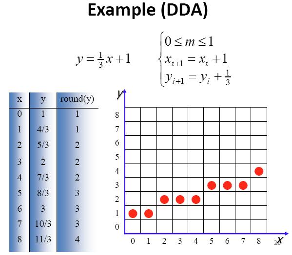
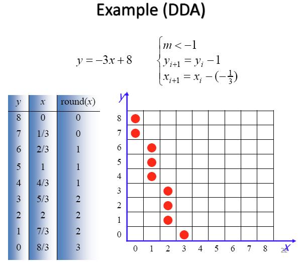
13 6. Digitize a line with end points (20, 10) and (30, 18). 7. Write the algorithm of the line drawing algorithm using Digital Differential Analyzer (DDA). 8. Using the DDA algorithm digitize a line with end points (10,15) and (15,30). 9. Digitize a line with end points (20, 10) and (30, 18) using DDA line drawing Algorithm.
.")
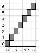
14 10. Implement the DDA algorithm to draw a line from (0,0) to (6,6). M=(6-0)/(6-0)=6/6 =1 XK+1=Xk+1 YK+1=Yk+m = Yk+1 Xk=0 Yk=0
15
16
17 11. Fill in the blanks (a) Sampling of the line at unit interval is carried out in one coordinate and corresponding integer value for the other coordinate is calculated. (b) Bresenham's line drawing algorithm is an accurate and efficient raster-line generating algorithm using only incremental integer calculations. 12. Compare DDA and Bresenham's line drawing algorithm. 13. Explain briefly the DDA line drawing algorithm. 14. Explain the Bresenham s line drawing algorithm with example.
18

19 Part 2: Graphics Primitives (Circle) 1. The process of drawing circle using Brute force method can be enhanced by taking greater advantage of the symmetry in a circle. Write the complete algorithm used to apply this enhancement. Mid-Point Circle Drawing Algorithm
, and obtain the first point on the circumference of a circle centered on the origin as (x 0, y 0 ) = (0, r) 2.")
20 2. Write the algorithm of drawing a circle using Midpoint Circle Algorithm 1. Input radius r and circle center (x c, y c ), and obtain the first point on the circumference of a circle centered on the origin as (x 0, y 0 ) = (0, r) 2. Calculate the initial value of the decision parameter as p 0 = ( 5 4 ) r 3. At each x k position, starting at k = 0, perform the following test: If p 0 < 0 the next point along the circle centered on (0,0) is (x k+1, y k ) and p k+1 = p k + 2(x k+1 ) + 1 Otherwise, the next point along the circle is (x k+1, y k 1 ) and p k+1 = p k + 2(x k + 1) + 1-2(y k + 1) 4. Determine symmetry points in the other seven octants. 5. Move each calculated pixel position (x, y) onto the circular path centered on(x c, y c ) and plot the coordinate values: x = x + x c, y = y + y c 6. Repeat steps 3 through 5 until x y.
 using midpoint")
21 3. Draw the circle or radius r=10 and center is at (3, 4) using midpoint algorithm
22
23 - Give three representations of circle, also give their equations. - Fill in the blanks In midpoint circle drawing algorithm if f (x, y) < 0 means (x, y) is inside the circle f ( x, y) = 0 means (x, y) is on the circle f (x, y) > 0 means (x, y) is outside the circle - Discuss scan conversion of circle with Bresenham s and midpoint circle algorithms.
Part 1: Introduction to computer graphics 1. Describe Each of the following: a. Computer Graphics. b. Computer Graphics API. c. CG s can be used in
 Part 1: Introduction to computer graphics 1. Describe Each of the following: a. Computer Graphics. b. Computer Graphics API. c. CG s can be used in solving Problems. d. Graphics Pipeline. e. Video Memory.
Types of CRT Display Devices. DVST-Direct View Storage Tube
 Examples of Computer Graphics Devices: CRT, EGA(Enhanced Graphic Adapter)/CGA/VGA/SVGA monitors, plotters, data matrix, laser printers, Films, flat panel devices, Video Digitizers, scanners, LCD Panels,
CS2401-COMPUTER GRAPHICS QUESTION BANK
 SRI VENKATESWARA COLLEGE OF ENGINEERING AND TECHNOLOGY THIRUPACHUR. CS2401-COMPUTER GRAPHICS QUESTION BANK UNIT-1-2D PRIMITIVES PART-A 1. Define Persistence Persistence is defined as the time it takes
Computer Graphics: Overview of Graphics Systems
 Computer Graphics: Overview of Graphics Systems By: A. H. Abdul Hafez Abdul.hafez@hku.edu.tr, 1 Outlines 1. Video Display Devices 2. Flat-panel displays 3. Video controller and Raster-Scan System 4. Coordinate
Comp 410/510. Computer Graphics Spring Introduction to Graphics Systems
 Comp 410/510 Computer Graphics Spring 2018 Introduction to Graphics Systems Computer Graphics Computer graphics deals with all aspects of 'creating images with a computer - Hardware (PC with graphics card)
B. TECH. VI SEM. I MID TERM EXAMINATION 2018
 B. TECH. VI SEM. I MID TERM EXAMINATION 2018 BRANCH : COMPUTER SCIENCE ENGINEERING ( CSE ) SUBJECT : 6CS4A COMPUTER GRAPHICS & MULTIMEDIA TECHNIQUES Q 1. Write down mid point ellipse drawing algorithm.
Downloads from: https://ravishbegusarai.wordpress.com/download_books/
 1. The graphics can be a. Drawing b. Photograph, movies c. Simulation 11. Vector graphics is composed of a. Pixels b. Paths c. Palette 2. Computer graphics was first used by a. William fetter in 1960 b.
2.2. VIDEO DISPLAY DEVICES
 Introduction to Computer Graphics (CS602) Lecture 02 Graphics Systems 2.1. Introduction of Graphics Systems With the massive development in the field of computer graphics a broad range of graphics hardware
Computer Graphics Prof. Sukhendu Das Dept. of Computer Science and Engineering Indian Institute of Technology, Madras Lecture - 5 CRT Display Devices
 Computer Graphics Prof. Sukhendu Das Dept. of Computer Science and Engineering Indian Institute of Technology, Madras Lecture - 5 CRT Display Devices Hello everybody, welcome back to the lecture on Computer
PTIK UNNES. Lecture 02. Conceptual Model for Computer Graphics and Graphics Hardware Issues
 E3024031 KOMPUTER GRAFIK E3024032 PRAKTIK KOMPUTER GRAFIK PTIK UNNES Lecture 02 Conceptual Model for Computer Graphics and Graphics Hardware Issues 2014 Learning Objectives After carefully listening this
1. Introduction. 1.1 Graphics Areas. Modeling: building specification of shape and appearance properties that can be stored in computer
 1. Introduction 1.1 Graphics Areas Modeling: building specification of shape and appearance properties that can be stored in computer Rendering: creation of shaded images from 3D computer models 2 Animation:
Objectives: Topics covered: Basic terminology Important Definitions Display Processor Raster and Vector Graphics Coordinate Systems Graphics Standards
 MODULE - 1 e-pg Pathshala Subject: Computer Science Paper: Computer Graphics and Visualization Module: Introduction to Computer Graphics Module No: CS/CGV/1 Quadrant 1 e-text Objectives: To get introduced
Computer Graphics. Raster Scan Display System, Rasterization, Refresh Rate, Video Basics and Scan Conversion
 Computer Graphics Raster Scan Display System, Rasterization, Refresh Rate, Video Basics and Scan Conversion 2 Refresh and Raster Scan Display System Used in Television Screens. Refresh CRT is point plotting
Monitor and Display Adapters UNIT 4
 Monitor and Display Adapters UNIT 4 TOPIC TO BE COVERED: 4.1: video Basics(CRT Parameters) 4.2: VGA monitors 4.3: Digital Display Technology- Thin Film Displays, Liquid Crystal Displays, Plasma Displays
CS 4451A: Computer Graphics. Why Computer Graphics?
 CS 445A: Computer Graphics z CCB, TT 9:3- Why Computer Graphics? z Fun! z Lots of uses: y Art, entertainment y Visualizing complex data/ideas y Concise representation of actions/commands/state y Design/task
Reading. 1. Displays and framebuffers. History. Modern graphics systems. Required
 Reading Required 1. Displays and s Angel, pp.19-31. Hearn & Baker, pp. 36-38, 154-157. OpenGL Programming Guide (available online): First four sections of chapter 2 First section of chapter 6 Optional
3. Displays and framebuffers
 3. Displays and framebuffers 1 Reading Required Angel, pp.19-31. Hearn & Baker, pp. 36-38, 154-157. Optional Foley et al., sections 1.5, 4.2-4.5 I.E. Sutherland. Sketchpad: a man-machine graphics communication
Displays. History. Cathode ray tubes (CRTs) Modern graphics systems. CSE 457, Autumn 2003 Graphics. » Whirlwind Computer - MIT, 1950
 Modern graphics systems. CSE 457, Autumn 2003 Graphics. » Whirlwind Computer - MIT, 1950") History Displays CSE 457, Autumn 2003 Graphics http://www.cs.washington.edu/education/courses/457/03au/» Whirlwind Computer - MIT, 1950 CRT display» SAGE air-defense system - middle 1950 s Whirlwind II
History Displays CSE 457, Autumn 2003 Graphics http://www.cs.washington.edu/education/courses/457/03au/» Whirlwind Computer - MIT, 1950 CRT display» SAGE air-defense system - middle 1950 s Whirlwind II
Display Systems. Viewing Images Rochester Institute of Technology
 Display Systems Viewing Images 1999 Rochester Institute of Technology In This Section... We will explore how display systems work. Cathode Ray Tube Television Computer Monitor Flat Panel Display Liquid
CMPE 466 COMPUTER GRAPHICS
 1 CMPE 466 COMPUTER GRAPHICS Chapter 2 Computer Graphics Hardware Instructor: D. Arifler Material based on - Computer Graphics with OpenGL, Fourth Edition by Donald Hearn, M. Pauline Baker, and Warren
These are used for producing a narrow and sharply focus beam of electrons.
 CATHOD RAY TUBE (CRT) A CRT is an electronic tube designed to display electrical data. The basic CRT consists of four major components. 1. Electron Gun 2. Focussing & Accelerating Anodes 3. Horizontal
Computer Graphics : Unit - I
 Computer Graphics Unit 1 Introduction: Computer Graphics it is a set of tools to create, manipulate and interact with pictures. Data is visualized through geometric shapes, colors and textures. Video Display
Computer Graphics Hardware
 Computer Graphics Hardware Kenneth H. Carpenter Department of Electrical and Computer Engineering Kansas State University January 26, 2001 - February 5, 2004 1 The CRT display The most commonly used type
2.4.1 Graphics. Graphics Principles: Example Screen Format IMAGE REPRESNTATION
 2.4.1 Graphics software programs available for the creation of computer graphics. (word art, Objects, shapes, colors, 2D, 3d) IMAGE REPRESNTATION A computer s display screen can be considered as being
MODULE I MCA COMPUTER GRAPHICS ADMN APPLICATIONS OF COMPUTER GRAPHICS
 MODULE 1 1. APPLICATIONS OF COMPUTER GRAPHICS Computer graphics is used in a lot of areas such as science, engineering, medicine, business, industry, government, art, entertainment, advertising, education
Display Technologies CMSC 435. Slides based on Dr. Luebke s slides
 Display Technologies CMSC 435 Slides based on Dr. Luebke s slides Recap: Transforms Basic 2D Transforms: Scaling, Shearing, Rotation, Reflection, Composition of 2D Transforms Basic 3D Transforms: Rotation,
Introduction to Computer Graphics
 Introduction to Computer Graphics R. J. Renka Department of Computer Science & Engineering University of North Texas 01/16/2010 Introduction Computer Graphics is a subfield of computer science concerned
Computer Graphics. Introduction
 Computer Graphics Introduction Introduction Computer Graphics : It involves display manipulation and storage of pictures and experimental data for proper visualization using a computer. Typically graphics
Reading. Displays and framebuffers. Modern graphics systems. History. Required. Angel, section 1.2, chapter 2 through 2.5. Related
 Reading Required Angel, section 1.2, chapter 2 through 2.5 Related Displays and framebuffers Hearn & Baker, Chapter 2, Overview of Graphics Systems OpenGL Programming Guide (the red book ): First four
Reading. Display Devices. Light Gathering. The human retina
 Reading Hear & Baker, Computer graphics (2 nd edition), Chapter 2: Video Display Devices, p. 36-48, Prentice Hall Display Devices Optional.E. Sutherland. Sketchpad: a man-machine graphics communication
Overview of Graphics Systems
 CHAPTER - 2 Overview of Graphics Systems Video Display Devices Instructions are stored in a display memory display file display list Modes: immediate each element is processed and displayed retained objects
VGA Port. Chapter 5. Pin 5 Pin 10. Pin 1. Pin 6. Pin 11. Pin 15. DB15 VGA Connector (front view) DB15 Connector. Red (R12) Green (T12) Blue (R11)
 DB15 Connector. Red (R12) Green (T12) Blue (R11)") Chapter 5 VGA Port The Spartan-3 Starter Kit board includes a VGA display port and DB15 connector, indicated as 5 in Figure 1-2. Connect this port directly to most PC monitors or flat-panel LCD displays
Chapter 5 VGA Port The Spartan-3 Starter Kit board includes a VGA display port and DB15 connector, indicated as 5 in Figure 1-2. Connect this port directly to most PC monitors or flat-panel LCD displays
Module 1: Digital Video Signal Processing Lecture 3: Characterisation of Video raster, Parameters of Analog TV systems, Signal bandwidth
 The Lecture Contains: Analog Video Raster Interlaced Scan Characterization of a video Raster Analog Color TV systems Signal Bandwidth Digital Video Parameters of a digital video Pixel Aspect Ratio file:///d
L14 - Video. L14: Spring 2005 Introductory Digital Systems Laboratory
 L14 - Video Slides 2-10 courtesy of Tayo Akinwande Take the graduate course, 6.973 consult Prof. Akinwande Some modifications of these slides by D. E. Troxel 1 How Do Displays Work? Electronic display
UNIT 1 INTRODUCTION TO COMPUTER
 UNIT 1 INTRODUCTION TO COMPUTER Introduction to Computer Structure 1.1 Introduction Objectives 1.2 Display Devices 1.2.1 Cathode Ray Tube Technology (CRT) 1.2.2 Random Scan Display 1.2.3 Raster Scan Display
Design of VGA Controller using VHDL for LCD Display using FPGA
 International OPEN ACCESS Journal Of Modern Engineering Research (IJMER) Design of VGA Controller using VHDL for LCD Display using FPGA Khan Huma Aftab 1, Monauwer Alam 2 1, 2 (Department of ECE, Integral
Computer Graphics NV1 (1DT383) Computer Graphics (1TT180) Cary Laxer, Ph.D. Visiting Lecturer
 Computer Graphics (1TT180) Cary Laxer, Ph.D. Visiting Lecturer") Computer Graphics NV1 (1DT383) Computer Graphics (1TT180) Cary Laxer, Ph.D. Visiting Lecturer Today s class Introductions Graphics system overview Thursday, October 25, 2007 Computer Graphics - Class 1
Computer Graphics NV1 (1DT383) Computer Graphics (1TT180) Cary Laxer, Ph.D. Visiting Lecturer Today s class Introductions Graphics system overview Thursday, October 25, 2007 Computer Graphics - Class 1
An Efficient SOC approach to Design CRT controller on CPLD s
 A Monthly Peer Reviewed Open Access International e-journal An Efficient SOC approach to Design CRT controller on CPLD s Abstract: Sudheer Kumar Marsakatla M.tech Student, Department of ECE, ACE Engineering
Video Display Unit (VDU)
") Video Display Unit (VDU) Historically derived from Cathode Ray Tube (CRT) technology Based on scan lines Horizontal flyback Vertical flyback Blank Active video Blank (vertical flyback takes several line
Video Display Unit (VDU) Historically derived from Cathode Ray Tube (CRT) technology Based on scan lines Horizontal flyback Vertical flyback Blank Active video Blank (vertical flyback takes several line
Elements of a Television System
 1 Elements of a Television System 1 Elements of a Television System The fundamental aim of a television system is to extend the sense of sight beyond its natural limits, along with the sound associated
Television History. Date / Place E. Nemer - 1
 Television History Television to see from a distance Earlier Selenium photosensitive cells were used for converting light from pictures into electrical signals Real breakthrough invention of CRT AT&T Bell
Display Devices & its Interfacing
 Display Devices & its Interfacing 3 Display systems are available in various technologies such as i) Cathode ray tubes (CRTs), ii) Liquid crystal displays (LCDs), iii) Plasma displays, and iv) Light emitting
Start with some basics: display devices
 Output Concepts Start with some basics: display devices Just how do we get images onto a screen? Most prevalent device: CRT Cathode Ray Tube AKA TV tube 2 Cathode Ray Tubes Cutting edge 1930 s technology
1 Your computer screen
 U.S.T.H.B / C.E.I.L Unit 7 Computer science L2 (S2) 1 Your computer screen Discuss the following questions. 1 What type of display do you have? 2 What size is the screen? 3 Can you watch TV on your PC
Graphics Concepts. David Cairns
 Graphics Concepts David Cairns Introduction The following material provides a brief introduction to some standard graphics concepts. For more detailed information, see DGJ, Chapter 2, p23. Display Modes
8/30/2010. Chapter 1: Data Storage. Bits and Bit Patterns. Boolean Operations. Gates. The Boolean operations AND, OR, and XOR (exclusive or)
") Chapter 1: Data Storage Bits and Bit Patterns 1.1 Bits and Their Storage 1.2 Main Memory 1.3 Mass Storage 1.4 Representing Information as Bit Patterns 1.5 The Binary System 1.6 Storing Integers 1.8 Data
Chapter 1: Data Storage Bits and Bit Patterns 1.1 Bits and Their Storage 1.2 Main Memory 1.3 Mass Storage 1.4 Representing Information as Bit Patterns 1.5 The Binary System 1.6 Storing Integers 1.8 Data
Screens; media that use additive primaries
 Image display Display is the final stage in the image processing pipeline: Continuous scenes are acquired and digitally processed. The display process essentially converts the discrete image back to continuous
Design and Implementation of an AHB VGA Peripheral
 Design and Implementation of an AHB VGA Peripheral 1 Module Overview Learn about VGA interface; Design and implement an AHB VGA peripheral; Program the peripheral using assembly; Lab Demonstration. System
Understanding Multimedia - Basics
 Understanding Multimedia - Basics Joemon Jose Web page: http://www.dcs.gla.ac.uk/~jj/teaching/demms4 Wednesday, 9 th January 2008 Design and Evaluation of Multimedia Systems Lectures video as a medium
Introduction & Colour
 Introduction & Colour Eric C. McCreath School of Computer Science The Australian National University ACT 0200 Australia ericm@cs.anu.edu.au Overview Computer Graphics Uses Basic Hardware and Software Colour
Chapter 3 Fundamental Concepts in Video. 3.1 Types of Video Signals 3.2 Analog Video 3.3 Digital Video
 Chapter 3 Fundamental Concepts in Video 3.1 Types of Video Signals 3.2 Analog Video 3.3 Digital Video 1 3.1 TYPES OF VIDEO SIGNALS 2 Types of Video Signals Video standards for managing analog output: A.
High Performance Raster Scan Displays
 High Performance Raster Scan Displays Item Type text; Proceedings Authors Fowler, Jon F. Publisher International Foundation for Telemetering Journal International Telemetering Conference Proceedings Rights
CHAPTER 4 OSCILLOSCOPES
 CHAPTER 4 OSCILLOSCOPES 4.1 Introduction The cathode ray oscilloscope generally referred to as the oscilloscope, is probably the most versatile electrical measuring instrument available. Some of electrical
IMS B007 A transputer based graphics board
 IMS B007 A transputer based graphics board INMOS Technical Note 12 Ray McConnell April 1987 72-TCH-012-01 You may not: 1. Modify the Materials or use them for any commercial purpose, or any public display,
Link download full: Test Bank for Business Data Communications Infrastructure Networking and Security 7th Edition by William
 Link download full: Test Bank for Business Data Communications Infrastructure Networking and Security 7th Edition by William https://digitalcontentmarket.org/download/test-bank-for-business-datacommunications-infrastructure-networking-and-security-7th-edition-by-william-andtom/
Chapter 3. Display Devices and Interfacing
 Chapter 3 Display Devices and Interfacing Monitor Details Collection of dots Matrix of dots creates character Monochrome monitor screen is collection of 350 *720 350 rows and each rows having 720 dots
decodes it along with the normal intensity signal, to determine how to modulate the three colour beams.
 Television Television as we know it today has hardly changed much since the 1950 s. Of course there have been improvements in stereo sound and closed captioning and better receivers for example but compared
VARIOUS DISPLAY TECHNOLOGIESS
 VARIOUS DISPLAY TECHNOLOGIESS Mr. Virat C. Gandhi 1 1 Computer Department, C. U. Shah Technical Institute of Diploma Studies Abstract A lot has been invented from the past till now in regards with the
CATHODE RAY OSCILLOSCOPE. Basic block diagrams Principle of operation Measurement of voltage, current and frequency
 CATHODE RAY OSCILLOSCOPE Basic block diagrams Principle of operation Measurement of voltage, current and frequency 103 INTRODUCTION: The cathode-ray oscilloscope (CRO) is a multipurpose display instrument
Hitachi Europe Ltd. ISSUE : app084/1.0 APPLICATION NOTE DATE : 28/04/99
 APPLICATION NOTE DATE : 28/04/99 Design Considerations when using a Hitachi Medium Resolution Dot Matrix Graphics LCD Introduction Hitachi produces a wide range of monochrome medium resolution dot matrix
TV Character Generator
 TV Character Generator TV CHARACTER GENERATOR There are many ways to show the results of a microcontroller process in a visual manner, ranging from very simple and cheap, such as lighting an LED, to much
Module 7. Video and Purchasing Components
 Module 7 Video and Purchasing Components Objectives 1. PC Hardware A.1.11 Evaluate video components and standards B.1.10 Evaluate monitors C.1.9 Evaluate and select appropriate components for a custom
MULTIMEDIA TECHNOLOGIES
 MULTIMEDIA TECHNOLOGIES LECTURE 08 VIDEO IMRAN IHSAN ASSISTANT PROFESSOR VIDEO Video streams are made up of a series of still images (frames) played one after another at high speed This fools the eye into
An Overview of Video Coding Algorithms
 An Overview of Video Coding Algorithms Prof. Ja-Ling Wu Department of Computer Science and Information Engineering National Taiwan University Video coding can be viewed as image compression with a temporal
Technology White Paper Plasma Displays. NEC Technologies Visual Systems Division
 Technology White Paper Plasma Displays NEC Technologies Visual Systems Division May 1998 1 What is a Color Plasma Display Panel? The term Plasma refers to a flat panel display technology that utilizes
Lecture Flat Panel Display Devices
 Lecture 13 6.111 Flat Panel Display Devices Outline Overview Flat Panel Display Devices How do Displays Work? Emissive Displays Light Valve Displays Display Drivers Addressing Schemes Display Timing Generator
Lossless Compression Algorithms for Direct- Write Lithography Systems
 Lossless Compression Algorithms for Direct- Write Lithography Systems Hsin-I Liu Video and Image Processing Lab Department of Electrical Engineering and Computer Science University of California at Berkeley
Time Varying Signals Part A Chemistry 838
 Part A Chemistry 838 Thomas V. Atkinson, Ph.D. Senior Academic Specialist Department of Chemistry Michigan State University East Lansing, MI 88 Table of Contents TABLE OF CONTENTS... TABLE OF TABLES...
Power Consumption Trends in Digital TVs produced since 2003
 Power Consumption Trends in Digital TVs produced since 2003 Prepared by Darrell J. King And Ratcharit Ponoum TIAX LLC 35 Hartwell Avenue Lexington, MA 02421 TIAX Reference No. D0543 for Consumer Electronics
To discuss. Types of video signals Analog Video Digital Video. Multimedia Computing (CSIT 410) 2
 2") Video Lecture-5 To discuss Types of video signals Analog Video Digital Video (CSIT 410) 2 Types of Video Signals Video Signals can be classified as 1. Composite Video 2. S-Video 3. Component Video (CSIT
Video Lecture-5 To discuss Types of video signals Analog Video Digital Video (CSIT 410) 2 Types of Video Signals Video Signals can be classified as 1. Composite Video 2. S-Video 3. Component Video (CSIT
Video Graphics Array (VGA)
") Video Graphics Array (VGA) Chris Knebel Ian Kaneshiro Josh Knebel Nathan Riopelle Image Source: Google Images 1 Contents History Design goals Evolution The protocol Signals Timing Voltages Our implementation
Video Graphics Array (VGA) Chris Knebel Ian Kaneshiro Josh Knebel Nathan Riopelle Image Source: Google Images 1 Contents History Design goals Evolution The protocol Signals Timing Voltages Our implementation
RICHLAND COLLEGE School of Engineering Business & Technology Rev. 0 W. Slonecker Rev. 1 (8/26/2012) J. Bradbury
 J. Bradbury") RICHLAND COLLEGE School of Engineering Business & Technology Rev. 0 W. Slonecker Rev. 1 (8/26/2012) J. Bradbury INTC 1307 Instrumentation Test Equipment Teaching Unit 8 Oscilloscopes Unit 8: Oscilloscopes
RICHLAND COLLEGE School of Engineering Business & Technology Rev. 0 W. Slonecker Rev. 1 (8/26/2012) J. Bradbury INTC 1307 Instrumentation Test Equipment Teaching Unit 8 Oscilloscopes Unit 8: Oscilloscopes
CATHODE-RAY OSCILLOSCOPE (CRO)
") CATHODE-RAY OSCILLOSCOPE (CRO) I N T R O D U C T I O N : The cathode-ray oscilloscope (CRO) is a multipurpose display instrument used for the observation, measurement, and analysis of waveforms by plotting
CATHODE-RAY OSCILLOSCOPE (CRO) I N T R O D U C T I O N : The cathode-ray oscilloscope (CRO) is a multipurpose display instrument used for the observation, measurement, and analysis of waveforms by plotting
Ch. 1: Audio/Image/Video Fundamentals Multimedia Systems. School of Electrical Engineering and Computer Science Oregon State University
 Ch. 1: Audio/Image/Video Fundamentals Multimedia Systems Prof. Ben Lee School of Electrical Engineering and Computer Science Oregon State University Outline Computer Representation of Audio Quantization
Chapter 2. RECORDING TECHNIQUES AND ANIMATION HARDWARE. 2.1 Real-Time Versus Single-Frame Animation
 Chapter 2. RECORDING TECHNIQUES AND ANIMATION HARDWARE Copyright (c) 1998 Rick Parent All rights reserved 2.1 Real-Time Versus Single-Frame Animation 2.2 Film Technology 2.3 Video Technology 2.4 Animation
7thSense Design Delta Media Server
 7thSense Design Delta Media Server Channel Alignment Guide: Warping and Blending Original by Andy B Adapted by Helen W (November 2015) 1 Trademark Information Delta, Delta Media Server, Delta Nano, Delta
CHAPTER 3 OSCILLOSCOPES AND SIGNAL GENERATOR
 CHAPTER 3 OSCILLOSCOPES AND SIGNAL GENERATOR OSCILLOSCOPE 3.1 Introduction The cathode ray oscilloscope (CRO) provides a visual presentation of any waveform applied to the input terminal. The oscilloscope
Implementation of an MPEG Codec on the Tilera TM 64 Processor
 1 Implementation of an MPEG Codec on the Tilera TM 64 Processor Whitney Flohr Supervisor: Mark Franklin, Ed Richter Department of Electrical and Systems Engineering Washington University in St. Louis Fall
DISPLAY TECHNOLOGIES. Group 6: Steve Lenhart, Ryan King, Ramsey Akl, and Andrew Scheib
 DISPLAY TECHNOLOGIES Group 6: Steve Lenhart, Ryan King, Ramsey Akl, and Andrew Scheib DISPLAY TECHNOLOGIES Group 6: Steve Lenhart, Ryan King, Ramsey Akl, and Andrew Scheib Introduction First computers
Multimedia. Course Code (Fall 2017) Fundamental Concepts in Video
 Fundamental Concepts in Video") Course Code 005636 (Fall 2017) Multimedia Fundamental Concepts in Video Prof. S. M. Riazul Islam, Dept. of Computer Engineering, Sejong University, Korea E-mail: riaz@sejong.ac.kr Outline Types of Video
Course Code 005636 (Fall 2017) Multimedia Fundamental Concepts in Video Prof. S. M. Riazul Islam, Dept. of Computer Engineering, Sejong University, Korea E-mail: riaz@sejong.ac.kr Outline Types of Video
F250. Advanced algorithm enables ultra high speed and maximum flexibility. High-performance Vision Sensor. Features
 High-performance Vision Sensor Advanced algorithm enables ultra high speed and maximum flexibility Features Inspection and positioning that was difficult with previous vision sensors is now surprisingly
Lab Determining the Screen Resolution of a Computer
 Lab 1.3.3 Determining the Screen Resolution of a Computer Objectives Determine the current screen resolution of a PC monitor. Determine the maximum resolution for the highest color quality. Calculate the
Television brian egan isnm 2004
 Introduction Mechanical early developments. Electrical how it works. Digital advantages over analogue. brian egan isnm Mechanical television First televisions were mechanical based on revolving disc, first
TechNote: MuraTool CA: 1 2/9/00. Figure 1: High contrast fringe ring mura on a microdisplay
 Mura: The Japanese word for blemish has been widely adopted by the display industry to describe almost all irregular luminosity variation defects in liquid crystal displays. Mura defects are caused by
Lecture 2 Video Formation and Representation
 2013 Spring Term 1 Lecture 2 Video Formation and Representation Wen-Hsiao Peng ( 彭文孝 ) Multimedia Architecture and Processing Lab (MAPL) Department of Computer Science National Chiao Tung University 1
Contents Circuits... 1
 Contents Circuits... 1 Categories of Circuits... 1 Description of the operations of circuits... 2 Classification of Combinational Logic... 2 1. Adder... 3 2. Decoder:... 3 Memory Address Decoder... 5 Encoder...
Data Representation. signals can vary continuously across an infinite range of values e.g., frequencies on an old-fashioned radio with a dial
 Data Representation 1 Analog vs. Digital there are two ways data can be stored electronically 1. analog signals represent data in a way that is analogous to real life signals can vary continuously across
Import and quantification of a micro titer plate image
 BioNumerics Tutorial: Import and quantification of a micro titer plate image 1 Aims BioNumerics can import character type data from TIFF images. This happens by quantification of the color intensity and/or
* This configuration has been updated to a 64K memory with a 32K-32K logical core split.
 398 PROCEEDINGS-FALL JOINT COMPUTER CONFERENCE, 1964 Figure 1. Image Processor. documents ranging from mathematical graphs to engineering drawings. Therefore, it seemed advisable to concentrate our efforts
THE OPERATION OF A CATHODE RAY TUBE
 THE OPERATION OF A CATHODE RAY TUBE OBJECT: To acquaint the student with the operation of a cathode ray tube, and to study the effect of varying potential differences on accelerated electrons. THEORY:
THE CAPABILITY to display a large number of gray
 292 JOURNAL OF DISPLAY TECHNOLOGY, VOL. 2, NO. 3, SEPTEMBER 2006 Integer Wavelets for Displaying Gray Shades in RMS Responding Displays T. N. Ruckmongathan, U. Manasa, R. Nethravathi, and A. R. Shashidhara
High-resolution screens have become a mainstay on modern smartphones. Initial. Displays 3.1 LCD
 3 Displays Figure 3.1. The University of Texas at Austin s Stallion Tiled Display, made up of 75 Dell 3007WPF LCDs with a total resolution of 307 megapixels (38400 8000 pixels) High-resolution screens
General Items: Reading Materials: Miscellaneous: Lecture 8 / Chapter 6 COSC1300/ITSC 1401/BCIS /19/2004. Tests? Questions? Anything?
 General Items: Tests? Questions? Anything? Reading Materials: Miscellaneous: F.Farahmand 1 / 14 File: lec7chap6f04.doc What is output? - A computer processes the data and generates output! - Also known
Multimedia Systems Video I (Basics of Analog and Digital Video) Mahdi Amiri April 2011 Sharif University of Technology
 Mahdi Amiri April 2011 Sharif University of Technology") Course Presentation Multimedia Systems Video I (Basics of Analog and Digital Video) Mahdi Amiri April 2011 Sharif University of Technology Video Visual Effect of Motion The visual effect of motion is due
Course Presentation Multimedia Systems Video I (Basics of Analog and Digital Video) Mahdi Amiri April 2011 Sharif University of Technology Video Visual Effect of Motion The visual effect of motion is due
CHAPTER 7 BASIC GRAPHICS, EVENTS AND GLOBAL DATA
 VERSION 1 BASIC GRAPHICS, EVENTS AND GLOBAL DATA CHAPTER 7 BASIC GRAPHICS, EVENTS, AND GLOBAL DATA In this chapter, the graphics features of TouchDevelop are introduced and then combined with scripts when
The BAT WAVE ANALYZER project
 The BAT WAVE ANALYZER project Conditions of Use The Bat Wave Analyzer program is free for personal use and can be redistributed provided it is not changed in any way, and no fee is requested. The Bat Wave
Revision: August 11, E Main Suite D Pullman, WA (509) Voice and Fax. 8 LEDs. Doc: page 1 of 9
 Voice and Fax. 8 LEDs. Doc: page 1 of 9") Digilent DIO4 Peripheral Board Reference Manual www.digilentinc.com Revision: August 11, 2004 215 E Main Suite D Pullman, WA 99163 (509) 334 6306 Voice and Fax Overview The DIO4 circuit board provides
Digilent DIO4 Peripheral Board Reference Manual www.digilentinc.com Revision: August 11, 2004 215 E Main Suite D Pullman, WA 99163 (509) 334 6306 Voice and Fax Overview The DIO4 circuit board provides
So far. Chapter 4 Color spaces Chapter 3 image representations. Bitmap grayscale. 1/21/09 CSE 40373/60373: Multimedia Systems
 So far. Chapter 4 Color spaces Chapter 3 image representations Bitmap grayscale page 1 8-bit color image Can show up to 256 colors Use color lookup table to map 256 of the 24-bit color (rather than choosing
Graphics Devices and Visual Perception. Human Vision. What is visual perception? Anatomy of the Eye. Spatial Resolution (Rods) Human Field of View
 Human Field of View") Graphics Devices and Visual Perception Human Vision and Perception CRT Displays Liquid Crystal Displays Video Controllers Display Controllers Input Devices Human Vision Eye + Retinal Receptors in eye provide
Graphics Devices and Visual Perception Human Vision and Perception CRT Displays Liquid Crystal Displays Video Controllers Display Controllers Input Devices Human Vision Eye + Retinal Receptors in eye provide
Pivoting Object Tracking System
 Pivoting Object Tracking System [CSEE 4840 Project Design - March 2009] Damian Ancukiewicz Applied Physics and Applied Mathematics Department da2260@columbia.edu Jinglin Shen Electrical Engineering Department