Digital (5hz to 500 Khz) Frequency-Meter
|
|
|
- Augustus Atkinson
- 5 years ago
- Views:
Transcription

1 Digital (5hz to 500 Khz) Frequency-Meter Posted on April 4, 2008, by Ibrahim KAMAL, in Sensor & Measurement, tagged Based on the famous AT89C52 microcontroller, this 500 Khz frequency-meter will be enough to trace and debug most of your circuits, to adjust 555 timers frequency and perform all kind of frequency measurements in Digital circuits. And once you have this tool between your hand, you will get used to it to the point of no-return! and you will say remember the days we adjusted the frequency by trial and error till we get it..! some basic notions about microcontrollers and general electronics skills. Note: This tutorial assumes you already have To understand the block diagram below, you should recall the simplest definition of frequency: the number of occurrences within a given time period. What we are trying to do is to count the number of electric pulses during a time of one second. To do this we need a counter, to count the pulses, and a timer so that every 1000 milliseconds, the processor stop counting, calculate the frequency and display it, then start counting again from zero. Below (figure 1) this is the principle of operation of a frequency meter, however, to build a reliable frequency meter, we will need to do some more mathematical operations. For example: Some operations will accurately predict the frequency before waiting for a whole second to elapse, which will also increase the refresh rate. Another minor upgrade is to to display the average of the last 5 reading rather than displaying the frequency instantaneously (which can cause lot of display flickering if the frequency being measured is not very stable).
2 figure 1 This project will be discussed in two Parts, the Hardware and the Software. PART 1: HARDWARE The Hardware Parts Lets start by this easy part,to make the project look far-or-less like a profession lab equipment, well I simply built it in an old Avo-Meter, one of those you find in stores for less than $5! (god bless china!), and then painted it all in black. (it was originally yellow!) and by the way, after I hacked that poor Avo-Meter, I also used the same leads for our frequency meter.
.")


3 As you can notice in the picture, there are four seven segments display. Finally you can also notice the two connections for the leads (Blue shaded area). Those connectors are standard for the test leads of most AVO meters and testing devices. The Display Before Getting into the electronics, here is a final trick: To make the display look even neater and Protect it from dust and scratches, simply add a thin plastic film on top of it (it will be firmly held in its place when the frequency meter is reassembled). The electronics

4 I am sure that you understand that to accomplish this project, we will need to perform some mathematical operations, as mentioned before, to increase the performance of the device. Thus we will rely on an AT89C52 microcontroller to perform all the required tasks in this project. The Display system
5 While being very simple (as you can see in this diagram), the display system can seem complicated due to the high number of connections (as you can see in the schematic below). The main idea for this display system, is to connect all the 7-segment cells together in parallel, but only power one of them in the same time. For example, here is the sequence to show the number 1984 : 1-Send the number 1 though the data lines 2-Energize the first cell while all other cells are off 3-wait for a short time delay (in my code i paused for 0.6 Millisecond) 4-Send the number 9 though the data lines 5-Energize the second cell while all other cells are off 6-wait for a short time delay.. 7-Send the number 8 though the data lines 8-Energize the third cell while all other cells are off 9-wait for a short time delay 10-Send the number 4 though the data lines 11-Energize the fourth cell while all other cells are off 12-wait for a short time delay 13-Start over from the step No: 1. Believe it or not, the human eye wont notice anything wrong, because, with the given delays the display will refresh at the rate of 375 cycles per second (375 Hz!) and the human eye can hardly notice some flickering in a display refreshing at 24 Hz.

 Input leads connections Nothing really critical about this part, since we only intend to measure TTL frequencies,")
6 Now That you understand the display process, you should be able to easily follow the schematic above. Here is a brief description Q 1,Q 2,Q 3,Q 4 2N2222 switching transistors to drive the 7-segment displays. DD1 to DD4 R 21 to R 24 R 35 to R 38 7-segmets display, common Anode type. Note that it is called 7 segments, but actually each cell contain 8 leds (7 leds for the digit, and 1 led for the decimal point) 1 Kohm pull up resistors 100Kohm pull down resistors U1 The AT89C52 Micro-Controller (actually you can only see the Port 0 and the 4 used pins of PORT 1) Input leads connections Nothing really critical about this part, since we only intend to measure TTL frequencies, the input is directly fed to the T O pin of the AT89C52, which will be used as a counter (more details about this in the software part).p 1 and P 2 are simply the two connections for the test leads. Note that in order to make any
7 kind of measurements on another circuit, the ground of the Measurement device and of the circuit being tested must be connected together, this is why there are at least two leads in any testing device (one for the Ground and one for the measured signal). Power Supply, clock generator, and reset button The Power supply here is not critical either, because the device will be powered from a 9V alkaline battery, so we don t need any filter capacitors, we just need to reduce 9V to 5V, and this is simply the job of the IC 7805 (Usually we add decoupling and filter capacitors when there is a lot of disturbance like in motor controllers, or AC to DC power supplies) This part is standard in any circuit containing an AT89C52 The switch SW 1 will reset the micro-controller and start the program from the beginning. C 1 and C 2 are 27 pf, any nearby value between 20 and 40 pf will work just fine. X is a 24 Mhz crystal. it is imperative to use a crystal of this frequency, which is the maximum frequency the AT89C52 can respond to. using a 12 Mhz crystals will result in maximum measurable frequency of 250 Khz instead of 500 Khz. Don t forget to connect the PIN 31 to the 5V, otherwise the micro controller wont work. PART 2: SOFTWARE NOTE: While I tried to make things as clear as i could, this is not a tutorial to explain to beginners what is a microcontroller and how to use it Now you have to bear in mind the simple block diagram of a frequency meter shown at the top of the page. You can download the whole code in one file here, but even a professional programmer would easily get lost in someone s else code, so my advice is to try to understand how it is working, and then write your own version of the code. The Main loop
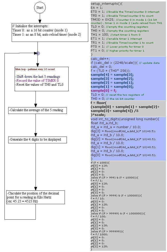
8 Now, here is a simplified flow chart of the main loop. Next to each box, you can see the corresponding source code, this can help you to understand how each step is programmed.
9
10 The Counter and the Timer The function count_pulses(), which is linked to the Interrupt 1, will be executed each time the TIMER 0 overflows. Actually this should never happen, because the counting registers are emptied every 1/5 second (if scale = 5, by default), but in case the timer overflows, we should increase the variable: scale, hence the counting variables will be emptied every 1/6 second, and if the the TIMER 0 still overflows, scale will be increased to 7, and so on, until the system stabilizes at a point where the counting registers are being emptied fast enough, then the calculated frequency is correct. count_pulses() interrupt 1 //counter 0 interrupt { if (scale < 200) scale++; } calc_and_disp() interrupt 3 { The function calc_and_disp() will be executed every 0.66 millisecond (this is defined by the variable TH1 in the setup_interrrupts() function) Each time this function is executed, one of the 4 7-segments is energized, and a corresponding digit is being sent, then, next time the function is called, the next digit is energized to show the next corresponding number And the sequence goes on as explained before in the display system. Note: dcnt is the variable used to select on of the 4 display cells. P0 = (bcd[dig[3- dcnt]] - pt[3- dcnt]) ; P1 = ord[3-dcnt]; dcnt++; if(dcnt > 3){ dcnt = 0; } } Now you should be able to build your own Frequency meter. To help you a litle more, I m giving you a zip file containing the full schematic, the PCB design and the source code. Source:
Digital Clock. Perry Andrews. A Project By. Based on the PIC16F84A Micro controller. Revision C
 Digital Clock A Project By Perry Andrews Based on the PIC16F84A Micro controller. Revision C 23 rd January 2011 Contents Contents... 2 Introduction... 2 Design and Development... 3 Construction... 7 Conclusion...
ECB DIGITAL ELECTRONICS PROJECT BASED LEARNING PROJECT REPORT ON 7 SEGMENT DIGITAL STOP WATCH USING DECODER
 ECB2212 - DIGITAL ELECTRONICS PROJECT BASED LEARNING PROJECT REPORT ON 7 SEGMENT DIGITAL STOP WATCH USING DECODER SUBMITTED BY ASHRAF HUSSAIN (160051601105) S SAMIULLAH (160051601059) CONTENTS >AIM >INTRODUCTION
Laboratory 8. Digital Circuits - Counter and LED Display
 Laboratory 8 Digital Circuits - Counter and Display Required Components: 2 1k resistors 1 10M resistor 3 0.1 F capacitor 1 555 timer 1 7490 decade counter 1 7447 BCD to decoder 1 MAN 6910 or LTD-482EC
8 PIN PIC PROGRAMMABLE BOARD (DEVELOPMENT BOARD & PROJECT BOARD)
") ESSENTIAL INFORMATION BUILD INSTRUCTIONS CHECKING YOUR PCB & FAULT-FINDING MECHANICAL DETAILS HOW THE KIT WORKS LEARN ABOUT PROGRAMMING WITH THIS 8 PIN PIC PROGRAMMABLE BOARD (DEVELOPMENT BOARD & PROJECT
ESSENTIAL INFORMATION BUILD INSTRUCTIONS CHECKING YOUR PCB & FAULT-FINDING MECHANICAL DETAILS HOW THE KIT WORKS LEARN ABOUT PROGRAMMING WITH THIS 8 PIN PIC PROGRAMMABLE BOARD (DEVELOPMENT BOARD & PROJECT
SWITCH: Microcontroller Touch-switch Design & Test (Part 2)
") SWITCH: Microcontroller Touch-switch Design & Test (Part 2) 2 nd Year Electronics Lab IMPERIAL COLLEGE LONDON v2.09 Table of Contents Equipment... 2 Aims... 2 Objectives... 2 Recommended Timetable... 2
SWITCH: Microcontroller Touch-switch Design & Test (Part 2) 2 nd Year Electronics Lab IMPERIAL COLLEGE LONDON v2.09 Table of Contents Equipment... 2 Aims... 2 Objectives... 2 Recommended Timetable... 2
Design and Implementation of Timer, GPIO, and 7-segment Peripherals
 Design and Implementation of Timer, GPIO, and 7-segment Peripherals 1 Module Overview Learn about timers, GPIO and 7-segment display; Design and implement an AHB timer, a GPIO peripheral, and a 7-segment
EECS145M 2000 Midterm #1 Page 1 Derenzo
 UNIVERSITY OF CALIFORNIA College of Engineering Electrical Engineering and Computer Sciences Department EECS 145M: Microcomputer Interfacing Laboratory Spring Midterm #1 (Closed book- calculators OK) Wednesday,
Published in A R DIGITECH
 Design of propeller clock by using 8051 Microcontroller Ahmed H. Al-Saadi*1 *1 (B.Sc. of Computer Engineering in Al Hussein University College of Engineering, Iraq) ah9@outlook.com*1 Abstract The propeller
Laboratory 11. Required Components: Objectives. Introduction. Digital Displays and Logic (modified from lab text by Alciatore)
") Laboratory 11 Digital Displays and Logic (modified from lab text by Alciatore) Required Components: 2x lk resistors 1x 10M resistor 3x 0.1 F capacitor 1x 555 timer 1x 7490 decade counter 1x 7447 BCD to
Laboratory 11 Digital Displays and Logic (modified from lab text by Alciatore) Required Components: 2x lk resistors 1x 10M resistor 3x 0.1 F capacitor 1x 555 timer 1x 7490 decade counter 1x 7447 BCD to
Reaction Game Kit MitchElectronics 2019
 Reaction Game Kit MitchElectronics 2019 www.mitchelectronics.co.uk CONTENTS Schematic 3 How It Works 4 Materials 6 Construction 8 Important Information 9 Page 2 SCHEMATIC Page 3 SCHEMATIC EXPLANATION The
TV Synchronism Generation with PIC Microcontroller
 TV Synchronism Generation with PIC Microcontroller With the widespread conversion of the TV transmission and coding standards, from the early analog (NTSC, PAL, SECAM) systems to the modern digital formats
6-DIGIT FREQUENCY METER, TACHOMETER, RATE METER, TIMER, PULSE TOTALIZER, PROCESS METER & TOTALIZER WITH RS-232 PENTA P6000
 6-DIGIT FREQUENCY METER, TACHOMETER, RATE METER, TIMER, PULSE TOTALIZER, PROCESS METER & TOTALIZER WITH RS-232 PENTA P6000 NEWPORT PRODUCT INFO MANUAL (HTML) - (PDF Version) P6000A/P5000 - INPUT OPTIONS
SignalTap Plus System Analyzer
 SignalTap Plus System Analyzer June 2000, ver. 1 Data Sheet Features Simultaneous internal programmable logic device (PLD) and external (board-level) logic analysis 32-channel external logic analyzer 166
VGA to PAL and NTSC converter
 VGA to PAL and NTSC converter Design and copyright by Tomi Engdahl 1996,1999 NOTE: There are few mistakes on the dawings shown on this page. I have recieved lots of questions related to them and I don't
University of Pennsylvania Department of Electrical and Systems Engineering. Digital Design Laboratory. Lab8 Calculator
 University of Pennsylvania Department of Electrical and Systems Engineering Digital Design Laboratory Purpose Lab Calculator The purpose of this lab is: 1. To get familiar with the use of shift registers
A MISSILE INSTRUMENTATION ENCODER
 A MISSILE INSTRUMENTATION ENCODER Item Type text; Proceedings Authors CONN, RAYMOND; BREEDLOVE, PHILLIP Publisher International Foundation for Telemetering Journal International Telemetering Conference
EE 367 Lab Part 1: Sequential Logic
 EE367: Introduction to Microprocessors Section 1.0 EE 367 Lab Part 1: Sequential Logic Contents 1 Preface 1 1.1 Things you need to do before arriving in the Laboratory............... 2 1.2 Summary of material
DIGITAL ELECTRONICS: LOGIC AND CLOCKS
 DIGITL ELECTRONICS: LOGIC ND CLOCKS L 6 INTRO: INTRODUCTION TO DISCRETE DIGITL LOGIC, MEMORY, ND CLOCKS GOLS In this experiment, we will learn about the most basic elements of digital electronics, from
XTAL Bank DDS Version 0.02 Sept Preliminary, highly likely to contain numerous errors
 XTAL Bank DDS Version 002 Sept 7 2012 Preliminary, highly likely to contain numerous errors The photo above shows the fully assembled Xtal Bank DDS with 2 DDS modules installed (The kit is normally only
UNIT V 8051 Microcontroller based Systems Design
 UNIT V 8051 Microcontroller based Systems Design INTERFACING TO ALPHANUMERIC DISPLAYS Many microprocessor-controlled instruments and machines need to display letters of the alphabet and numbers. Light
Experiment 7 Fall 2012
 10/30/12 Experiment 7 Fall 2012 Experiment 7 Fall 2012 Count UP/DOWN Timer Using The SPI Subsystem Due: Week 9 lab Sessions (10/23/2012) Design and implement a one second interval (and high speed 0.05
PHYSICS 5620 LAB 9 Basic Digital Circuits and Flip-Flops
 PHYSICS 5620 LAB 9 Basic Digital Circuits and Flip-Flops Objective Construct a two-bit binary decoder. Study multiplexers (MUX) and demultiplexers (DEMUX). Construct an RS flip-flop from discrete gates.
Copyright 2011 by Enoch Hwang, Ph.D. and Global Specialties. All rights reserved. Printed in Taiwan.
 Copyright 2011 by Enoch Hwang, Ph.D. and Global Specialties All rights reserved. Printed in Taiwan. No part of this publication may be reproduced, stored in a retrieval system or transmitted, in any form
Chapter 3: Sequential Logic Systems
 Chapter 3: Sequential Logic Systems 1. The S-R Latch Learning Objectives: At the end of this topic you should be able to: design a Set-Reset latch based on NAND gates; complete a sequential truth table
V6118 EM MICROELECTRONIC - MARIN SA. 2, 4 and 8 Mutiplex LCD Driver
 EM MICROELECTRONIC - MARIN SA 2, 4 and 8 Mutiplex LCD Driver Description The is a universal low multiplex LCD driver. The version 2 drives two ways multiplex (two blackplanes) LCD, the version 4, four
CSCB58 - Lab 4. Prelab /3 Part I (in-lab) /1 Part II (in-lab) /1 Part III (in-lab) /2 TOTAL /8
 /1 Part II (in-lab) /1 Part III (in-lab) /2 TOTAL /8") CSCB58 - Lab 4 Clocks and Counters Learning Objectives The purpose of this lab is to learn how to create counters and to be able to control when operations occur when the actual clock rate is much faster.
CSCB58 - Lab 4 Clocks and Counters Learning Objectives The purpose of this lab is to learn how to create counters and to be able to control when operations occur when the actual clock rate is much faster.
Display for the Virginia Museum of Science Digital Communications
 Display for the Virginia Museum of Science Digital Communications Date Submitted: 6 October 00 Independent Research Project EE 49 Digital Communications Cadets: Joseph Wunder Brian Holt I. Introduction
EXPERIMENT #6 DIGITAL BASICS
 EXPERIMENT #6 DIGITL SICS Digital electronics is based on the binary number system. Instead of having signals which can vary continuously as in analog circuits, digital signals are characterized by only
Chapter 4. Logic Design
 Chapter 4 Logic Design 4.1 Introduction. In previous Chapter we studied gates and combinational circuits, which made by gates (AND, OR, NOT etc.). That can be represented by circuit diagram, truth table
Technology Control Technology
 L e a v i n g C e r t i f i c a t e Technology Control Technology P I C A X E 1 8 X Prog. 1.SOUND Output Prog. 3 OUTPUT & WAIT Prog. 6 LOOP Prog. 7...Seven Segment Display Prog. 8...Single Traffic Light
Tutorial Introduction
 Tutorial Introduction PURPOSE - To explain how to configure and use the in common applications OBJECTIVES: - Identify the steps to set up and configure the. - Identify techniques for maximizing the accuracy
Traffic Light Controller
 Traffic Light Controller Four Way Intersection Traffic Light System Fall-2017 James Todd, Thierno Barry, Andrew Tamer, Gurashish Grewal Electrical and Computer Engineering Department School of Engineering
Review : 2 Release Date : 2019 Last Amendment : 2013 Course Code : SKEE 2742 Procedure Number : PK-UTM-FKE-(0)-10
-10") School Course Name : : ELECTRICAL ENGINEERING 2 ND YEAR ELECTRONIC DESIGN LAB Review : 2 Release Date : 2019 Last Amendment : 2013 Course Code : SKEE 2742 Procedure Number : PK-UTM-FKE-(0)-10 School of
School Course Name : : ELECTRICAL ENGINEERING 2 ND YEAR ELECTRONIC DESIGN LAB Review : 2 Release Date : 2019 Last Amendment : 2013 Course Code : SKEE 2742 Procedure Number : PK-UTM-FKE-(0)-10 School of
16 Stage Bi-Directional LED Sequencer
 16 Stage Bi-Directional LED Sequencer The bi-directional sequencer uses a 4 bit binary up/down counter (CD4516) and two "1 of 8 line decoders" (74HC138 or 74HCT138) to generate the popular "Night Rider"
N3ZI Digital Dial Manual For kit with Backlit LCD Rev 4.00 Jan 2013 PCB
 N3ZI Digital Dial Manual For kit with Backlit LCD Rev 4.00 Jan 2013 PCB Kit Components Item Qty Designator Part Color/Marking PCB 1 LCD Display 1 LCD 1602 Volt Regulator 1 U1 78L05, Black TO-92 Prescaler
Spring 2011 Microprocessors B Course Project (30% of your course Grade)
") Course Project guidelines Spring 2011 Microprocessors B 17.384 Course Project (30% of your course Grade) Overall Guidelines Design a fairly complex system that contains at least one microcontroller (the
Course Project guidelines Spring 2011 Microprocessors B 17.384 Course Project (30% of your course Grade) Overall Guidelines Design a fairly complex system that contains at least one microcontroller (the
Flexible Counter Series in DIN size 24 x 48 mm
 Flexible Counter Series in DIN size 24 x 48 mm high contrast 8-digit LCD display or brilliant 6-digit LED display different supply voltages available: independent of mains supply with lithium battery or
16-BIT LOAD CELL/DUAL STATUS INPUT
 16-BIT LOAD CELL/DUAL STATUS INPUT On-board Excitation. +5VDC, (120mA). State-of-the-art Electromagnetic Noise Suppression Circuitry. Ensures signal integrity even in harsh EMC environments. Optional Excitation
Data Sheet. Electronic displays
 Data Pack F Issued November 0 029629 Data Sheet Electronic displays Three types of display are available; each has differences as far as the display appearance, operation and electrical characteristics
N3ZI Digital Dial Manual For kit with Serial LCD Rev 3.04 Aug 2012
 N3ZI Digital Dial Manual For kit with Serial LCD Rev 3.04 Aug 2012 Kit properly assembled and configured for Standard Serial LCD (LCD Not yet connected) Kit Components Item Qty Designator Part Color/Marking
Lesson Sequence: S4A (Scratch for Arduino)
") Lesson Sequence: S4A (Scratch for Arduino) Rationale: STE(A)M education (STEM with the added Arts element) brings together strands of curriculum with a logical integration. The inclusion of CODING in STE(A)M
Lesson Sequence: S4A (Scratch for Arduino) Rationale: STE(A)M education (STEM with the added Arts element) brings together strands of curriculum with a logical integration. The inclusion of CODING in STE(A)M
Objectives: Learn how LED displays work Be able to output your name on the display
 Objectives: Learn how LED displays work Be able to output your name on the display By the end of this session: You will know how simple LED displays work and be able to make them give a useful output.
Microcontrollers. Outline. Class 4: Timer/Counters. March 28, Timer/Counter Introduction. Timers as a Timebase.
 Microcontrollers Class 4: Timer/Counters March 28, 2011 Outline Timer/Counter Introduction Timers as a Timebase Timers for PWM Outline Timer/Counter Introduction Timers as a Timebase Timers for PWM Outline
7 SEGMENT LED DISPLAY KIT
 ESSENTIAL INFORMATION BUILD INSTRUCTIONS CHECKING YOUR PCB & FAULT-FINDING MECHANICAL DETAILS HOW THE KIT WORKS CREATE YOUR OWN SCORE BOARD WITH THIS 7 SEGMENT LED DISPLAY KIT Version 2.0 Which pages of
( stored on ) also accessible from
 also accessible from") ( stored on http://www.stealthskater.com/articles/walkietalkie.doc ) also accessible from http://www.stealthskater.com/articles.htm ) Two walkie-talkies can be put to good use on a camping trip by keeping
( stored on http://www.stealthskater.com/articles/walkietalkie.doc ) also accessible from http://www.stealthskater.com/articles.htm ) Two walkie-talkies can be put to good use on a camping trip by keeping
Keyboard Controlled Scoreboard
 Universities Research Journal 2011, Vol. 4, No. 4 Keyboard Controlled Scoreboard Kyaw Hlaing 1 and Win Swe 2 Abstract The objective of this research work is to design a keyboard controlled scoreboard that
The Micropython Microcontroller
 Please do not remove this manual from the lab. It is available via Canvas Electronics Aims of this experiment Explore the capabilities of a modern microcontroller and some peripheral devices. Understand
Report on 4-bit Counter design Report- 1, 2. Report on D- Flipflop. Course project for ECE533
 Report on 4-bit Counter design Report- 1, 2. Report on D- Flipflop Course project for ECE533 I. Objective: REPORT-I The objective of this project is to design a 4-bit counter and implement it into a chip
ECE 372 Microcontroller Design
 E.g. Port A, Port B Used to interface with many devices Switches LEDs LCD Keypads Relays Stepper Motors Interface with digital IO requires us to connect the devices correctly and write code to interface
EPROM pattern generator with "Genlock"
 EPROM pattern generator with "Genlock" This generator uses an EPROM to store several pictures that can then be selected by means of a thumb-wheel switch. Alternatively, if the pictures stored are in a
M i N T the refreshing technologies
 School of Engineering Science Burnaby, BC V5A1S6 http://www.sfu.ca/~sschang/mint 340-2001@sfu.ca Sept 6, 2001 Dr. Andrew Rawicz School of Engineering Science Simon Fraser University Burnaby, British Columbia
TV Character Generator
 TV Character Generator TV CHARACTER GENERATOR There are many ways to show the results of a microcontroller process in a visual manner, ranging from very simple and cheap, such as lighting an LED, to much
PHYS 3322 Modern Laboratory Methods I Digital Devices
 PHYS 3322 Modern Laboratory Methods I Digital Devices Purpose This experiment will introduce you to the basic operating principles of digital electronic devices. Background These circuits are called digital
Digital Circuits I and II Nov. 17, 1999
 Physics 623 Digital Circuits I and II Nov. 17, 1999 Digital Circuits I 1 Purpose To introduce the basic principles of digital circuitry. To understand the small signal response of various gates and circuits
Triple RTD. On-board Digital Signal Processor. Linearization RTDs 20 Hz averaged outputs 16-bit precision comparator function.
 Triple RTD SMART INPUT MODULE State-of-the-art Electromagnetic Noise Suppression Circuitry. Ensures signal integrity even in harsh EMC environments. On-board Digital Signal Processor. Linearization RTDs
Experiment # 4 Counters and Logic Analyzer
 EE20L - Introduction to Digital Circuits Experiment # 4. Synopsis: Experiment # 4 Counters and Logic Analyzer In this lab we will build an up-counter and a down-counter using 74LS76A - Flip Flops. The
University of Illinois at Urbana-Champaign
 University of Illinois at Urbana-Champaign Digital Electronics Laboratory Physics Department Physics 40 Laboratory Experiment 3: CMOS Digital Logic. Introduction The purpose of this lab is to continue
SDA 3302 Family. GHz PLL with I 2 C Bus and Four Chip Addresses
 GHz PLL with I 2 C Bus and Four Chip Addresses Preliminary Data Features 1-chip system for MPU control (I 2 C bus) 4 programmable chip addresses Short pull-in time for quick channel switch-over and optimized
IT T35 Digital system desigm y - ii /s - iii
 UNIT - III Sequential Logic I Sequential circuits: latches flip flops analysis of clocked sequential circuits state reduction and assignments Registers and Counters: Registers shift registers ripple counters
CPE 200L LABORATORY 3: SEQUENTIAL LOGIC CIRCUITS UNIVERSITY OF NEVADA, LAS VEGAS GOALS: BACKGROUND: SR FLIP-FLOP/LATCH
 CPE 200L LABORATORY 3: SEUENTIAL LOGIC CIRCUITS DEPARTMENT OF ELECTRICAL AND COMPUTER ENGINEERING UNIVERSITY OF NEVADA, LAS VEGAS GOALS: Learn to use Function Generator and Oscilloscope on the breadboard.
Computer Systems Architecture
 Computer Systems Architecture Fundamentals Of Digital Logic 1 Our Goal Understand Fundamentals and basics Concepts How computers work at the lowest level Avoid whenever possible Complexity Implementation
7 SegmneDisplay Unit With High Bright Characters (D1SC-N : W32 H57mm, D1SA Series: W11 H22mm)
") SC-N/SA Series 7 Segment Display Unit 7 SegmneDisplay Unit With High Bright Characters (SC-N : W32 H57mm, SA Series: W H22mm) Features Selectable decimal (0 to 9) or hexadecimal (0 to 9, A to F) indication
SC-N/SA Series 7 Segment Display Unit 7 SegmneDisplay Unit With High Bright Characters (SC-N : W32 H57mm, SA Series: W H22mm) Features Selectable decimal (0 to 9) or hexadecimal (0 to 9, A to F) indication
Be a part of the circuit. Brick'R'knowledge. Set overview.
 Be a part of the circuit. Brick'R'knowledge Set overview www.brickrknowledge.com (Rx) SDA SCL 5V GND (10:1) I2C, max 20V (Tx) GPIO0 RESET int, max 10V GND 1 5V GND 1 2 5V 5V GND 1 2 3 Brick R knowledge
Bill of Materials: Super Simple Water Level Control PART NO
 Super Simple Water Level Control PART NO. 2169109 Design a simple water controller in which electrodes are required to sense high and low water levels in a tank. Whenever the water level falls below the
MODULAR DIGITAL ELECTRONICS TRAINING SYSTEM
 MODULAR DIGITAL ELECTRONICS TRAINING SYSTEM MDETS UCTECH's Modular Digital Electronics Training System is a modular course covering the fundamentals, concepts, theory and applications of digital electronics.
MICROMASTER Encoder Module
 MICROMASTER Encoder Module Operating Instructions Issue 01/02 User Documentation Foreword Issue 01/02 1 Foreword Qualified Personnel For the purpose of this Instruction Manual and product labels, a Qualified
Lab 3: Timer and Clock
 CS4101 Introduction to Embedded Systems Lab 3: Timer and Clock Prof. Chung-Ta King Department of Computer Science, Taiwan Introduction In this lab, we will learn more advanced timer operations and clocking
International Journal of scientific research and management (IJSRM) Volume 1 Issue 6 Pages Website: ISSN (e):
 Volume 1 Issue 6 Pages Website: ISSN (e):") International Journal of scientific research and management (IJSRM) Volume 1 Issue 6 Pages 346-351 2013 Website: www.ijsrm.in ISSN (e): 2321-3418 Design and Development of a 6-Digit Microcontroller Based
International Journal of scientific research and management (IJSRM) Volume 1 Issue 6 Pages 346-351 2013 Website: www.ijsrm.in ISSN (e): 2321-3418 Design and Development of a 6-Digit Microcontroller Based
EEM Digital Systems II
 ANADOLU UNIVERSITY DEPARTMENT OF ELECTRICAL AND ELECTRONICS ENGINEERING EEM 334 - Digital Systems II LAB 3 FPGA HARDWARE IMPLEMENTATION Purpose In the first experiment, four bit adder design was prepared
WINTER 15 EXAMINATION Model Answer
 Important Instructions to examiners: 1) The answers should be examined by key words and not as word-to-word as given in the model answer scheme. 2) The model answer and the answer written by candidate
Decade Counters Mod-5 counter: Decade Counter:
 Decade Counters We can design a decade counter using cascade of mod-5 and mod-2 counters. Mod-2 counter is just a single flip-flop with the two stable states as 0 and 1. Mod-5 counter: A typical mod-5
Alice EduPad Board. User s Guide Version /11/2017
 Alice EduPad Board User s Guide Version 1.02 08/11/2017 1 Table OF Contents Chapter 1. Overview... 3 1.1 Welcome... 3 1.2 Launchpad features... 4 1.3 Alice EduPad hardware features... 4 Chapter 2. Software
35058-TE. PLJ-6LED-A LED Frequency Display Module Manual
 35058-TE 6-digit LED Frequency Counter Module GREEN DISPLAY LED Frequency Display Module Manual Three Swords Studio Light Rongsheng 2013, March Guangxi Nanning Longan Information including Links and Code
Introduction to Digital Electronics
 Introduction to Digital Electronics by Agner Fog, 2018-10-15. Contents 1. Number systems... 3 1.1. Decimal, binary, and hexadecimal numbers... 3 1.2. Conversion from another number system to decimal...
Marks and Grades Project
 Marks and Grades Project This project uses the HCS12 to allow for user input of class grades to determine the letter grade and overall GPA for all classes. Interface: The left-most DIP switch (SW1) is
Laboratory 10. Required Components: Objectives. Introduction. Digital Circuits - Logic and Latching (modified from lab text by Alciatore)
") Laboratory 10 Digital Circuits - Logic and Latching (modified from lab text by Alciatore) Required Components: 1x 330 resistor 4x 1k resistor 2x 0.F capacitor 1x 2N3904 small signal transistor 1x LED 1x
Laboratory 10 Digital Circuits - Logic and Latching (modified from lab text by Alciatore) Required Components: 1x 330 resistor 4x 1k resistor 2x 0.F capacitor 1x 2N3904 small signal transistor 1x LED 1x
A/D and D/A convertor 0(4) 24 ma DC, 16 bits
 24 ma DC, 16 bits") A/D and D/A convertor 0(4) 24 ma DC, 6 bits ZAT-DV The board contains independent isolated input A/D convertors for measurement of DC current signals 0(4) ma from technological convertors and sensors and
A/D and D/A convertor 0(4) 24 ma DC, 6 bits ZAT-DV The board contains independent isolated input A/D convertors for measurement of DC current signals 0(4) ma from technological convertors and sensors and
TSIU03, SYSTEM DESIGN. How to Describe a HW Circuit
 TSIU03 TSIU03, SYSTEM DESIGN How to Describe a HW Circuit Sometimes it is difficult for students to describe a hardware circuit. This document shows how to do it in order to present all the relevant information
Evaluation Board For ADF Integrated VCO & Frequency Synthesizer
 a Evaluation Board For ADF4360-1 Integrated VCO & Frequency Synthesizer EVAL-ADF4360-1EB1 FEATURES Self-Contained Board for generating RF frequencies Flexibility for Reference Input, Output frequency,
Arbor Scientific PO Box 2750 Ann Arbor, Michigan (800) Timer & Photogates 2.0 P Owners Manual
 Timer & Photogates 2.0 P Owners Manual") Arbor Scientific PO Box 2750 Ann Arbor, Michigan 48108 www.arborsci.com (800) 367-6695 Timer & Photogates 2.0 P4-1450 Owners Manual Stopwatch 0.01 second resolution to 999999.99 seconds Count FCC Compliance
Arbor Scientific PO Box 2750 Ann Arbor, Michigan 48108 www.arborsci.com (800) 367-6695 Timer & Photogates 2.0 P4-1450 Owners Manual Stopwatch 0.01 second resolution to 999999.99 seconds Count FCC Compliance
An Enhanced MM MHz Generator
 An Enhanced MM5369-60 MHz Generator Author: OVERVIEW Jim Nagy London Ontario email: nagy@wwdc.com I call my idea an 'MM5369E' as it represents the equivalent of a 5369 IC plus all the 'glue' necessary
Improved Synchronization System for Thermal Power Station
 Improved Synchronization System for Thermal Power Station Lokeshkumar.C 1, Logeshkumar.E 2, Harikrishnan.M 3, Margaret 4, Dr.K.Sathiyasekar 5 UG Students, Department of EEE, S.A.Engineering College, Chennai,
DIY KIT MHZ 8-DIGIT FREQUENCY METER
 This kit is a stand-alone frequency meter capable of measuring repetitive signals up to a frequency of 50MHz. It has two frequency ranges (15 and 50 MHz) as well as two sampling rates (0.1 and 1 second).
uresearch GRAVITECH.US GRAVITECH GROUP Copyright 2007 MicroResearch GRAVITECH GROUP
 GRAVITECH.US uresearch GRAVITECH GROUP Description The I2C-7SEG board is a 5-pin CMOS device that provides 4-digit of 7-segment display using I 2 C bus. There are no external components required. Only
LED Array Board.
 LED Array Board www.matrixtsl.com EB087 Contents About This Document 2 General Information 3 Board Layout 4 Testing This Product 5 Circuit Description 6 Circuit Diagram 7 About This Document This document
1. Synopsis: 2. Description of the Circuit:
 Design of a Binary Number Lock (using schematic entry method) 1. Synopsis: This lab gives you more exercise in schematic entry, state machine design using the one-hot state method, further understanding
Entry Level Tool II. Reference Manual. System Level Solutions, Inc. (USA) Murphy Avenue San Martin, CA (408) Version : 1.0.
 Murphy Avenue San Martin, CA (408) Version : 1.0.") Entry Level Tool II Reference Manual, Inc. (USA) 14100 Murphy Avenue San Martin, CA 95046 (408) 852-0067 http://www.slscorp.com Version : 1.0.3 Date : October 7, 2005 Copyright 2005-2006,, Inc. (SLS) All
Entry Level Tool II Reference Manual, Inc. (USA) 14100 Murphy Avenue San Martin, CA 95046 (408) 852-0067 http://www.slscorp.com Version : 1.0.3 Date : October 7, 2005 Copyright 2005-2006,, Inc. (SLS) All
WELDING CONTROL UNIT: TE 450 USER MANUAL
 j WELDING CONTROL UNIT: TE 450 USER MANUAL RELEASE SOFTWARE No. 1.50 DOCUMENT NUMBER: MAN 4097 EDITION: MARCH 1998 This page is left blank intentionally. 2 / 34 TABLE OF CONTENTS SUBJECTS PAGE WELDING
USER'S MANUAL. Getting started with ALEXAN ATMEL AT89C2051/AT89C4051 Training Module - 1
 USER'S MANUAL Getting started with ALEXAN ATMEL AT89C05/AT89C405 Training Module - Version.0 Copyright 006 Ace Electronic Technology Inc. All Rights Reserved Alexan 05/405 TM- v..0 Page of 7 About This
Digital Stopwatch Timer Circuit Using 555timer and CD4033
 Digital Stopwatch Timer Circuit Using 555timer and CD4033 Kokila.C 1, Kousalya.J.R 2, Madhumitha.K 3, Nandhini.P 4 and Mr.Martin Joel Ratnam 5 UG Scholar, Department of ECE, Adhiyamaan College of Engineering,
DDS VFO CONSTRUCTION MANUAL. DDS VFO Construction Manual Issue 1.1 Page 1
 DDS VFO CONSTRUCTION MANUAL DDS VFO Construction Manual Issue 1.1 Page 1 Important Please read before starting assembly STATIC PRECAUTION The DDS VFO kit contains the following components which can be
Preliminary Design Report. Remote Fencing Scoreboard Gator FenceBox
 EEL 4924 Electrical Engineering Design (Senior Design) Preliminary Design Report 2 February 2012 Remote Fencing Scoreboard Gator FenceBox Team Members: Adrian Montero Team Antero Alexander Quintero Project
Chapter 5 Flip-Flops and Related Devices
 Chapter 5 Flip-Flops and Related Devices Chapter 5 Objectives Selected areas covered in this chapter: Constructing/analyzing operation of latch flip-flops made from NAND or NOR gates. Differences of synchronous/asynchronous
FLIP-FLOPS AND RELATED DEVICES
 C H A P T E R 5 FLIP-FLOPS AND RELATED DEVICES OUTLINE 5- NAND Gate Latch 5-2 NOR Gate Latch 5-3 Troubleshooting Case Study 5-4 Digital Pulses 5-5 Clock Signals and Clocked Flip-Flops 5-6 Clocked S-R Flip-Flop
Lab #5: Design Example: Keypad Scanner and Encoder - Part 1 (120 pts)
") Nate Pihlstrom, npihlstr@uccs.edu Lab #5: Design Example: Keypad Scanner and Encoder - Part 1 (120 pts) Objective The objective of lab assignments 5 through 9 are to systematically design and implement
Nate Pihlstrom, npihlstr@uccs.edu Lab #5: Design Example: Keypad Scanner and Encoder - Part 1 (120 pts) Objective The objective of lab assignments 5 through 9 are to systematically design and implement
Experimental Study to Show the Effect of Bouncing On Digital Systems
 Journal Name, Vol. 1, Journal of Networks and Telecommunication Systems, Vol. 1 (1), 28-38, September, 2015 ISSN: Pending,, Published online: www.unitedscholars.net/archive Experimental Study to Show the
Flip Flop. S-R Flip Flop. Sequential Circuits. Block diagram. Prepared by:- Anwar Bari
 Sequential Circuits The combinational circuit does not use any memory. Hence the previous state of input does not have any effect on the present state of the circuit. But sequential circuit has memory
Christmas LED Snowflake Project
 Christmas LED Snowflake Project Version 1.1 (01/12/2008) The snowflake is a follow-on from my Christmas star project from a few years ago. This year I decided to make a display using only white LEDs, shaped
DSO138mini Troubleshooting Guide
 DSO138mini Troubleshooting Guide Applicable main board: 109-13800-00I Applicable analog board: 109-13801-00H 1. Frequently Found Problems 1) LCD completely dark. No backlight 2) LCD lights up but no display
Digital Effects Pedal Description Ross Jongeward 10 December 2014
 Digital Effects Pedal Description Ross Jongeward 10 December 2014 1 Contents Section Number Title Page 1.1 Introduction..3 2.1 Project Electrical Specifications..3 2.1.1 Project Specifications...3 2.2.1