Coherent Receiver for L-band
|
|
|
- Susanna Nicholson
- 5 years ago
- Views:
Transcription
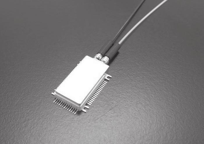
1 INFOCOMMUNICATIONS Coherent Receiver for L-band Misaki GOTOH*, Kenji SAKURAI, Munetaka KUROKAWA, Ken ASHIZAWA, Yoshihiro YONEDA, and Yasushi FUJIMURA As a solution to the rapidly increasing optical traffic, 1 Gbit/s transmission systems using the digital coherent optical communication technology has been adopted in high-speed and large-capacity optical transmission. Optical transceivers are required to be operable in the long wavelength band (L-band) in addition to the conventional band (C-band). Based on the design of C-band receivers, we have developed compact optical receivers for the L-band operation. This paper presents the design and typical characteristics of the new optical receivers Keywords: L-band, coherent receiver, 9 hybrid 1. Introduction Recently, the demand for diverse networks has been increasing rapidly due to the widespread use of the Internet of Things (IoT) technology in various fields, high-definition video distribution services, and new cloud computing applications. To meet the demand, large-capacity transmission systems that use digital coherent optical communication technologies, such as Dual-Polarization Quadrature Phase Shift Keying (DP-QPSK)* 1 and have transmission speed exceeding 1 Gbit/s have been widely deployed for metro networks and long haul networks around the world. The data traffic on these networks is expected to increase in speed and volume, and therefore multiplexing using the L-band (in addition to the conventional C-band) will be necessary to increase the symbol rate and enhance multilevel encoding. Notably, the transmission capacity can be doubled by expansion to the L-band where two bands are used in parallel on existing fiber optics, enabling the transmission capacity to be increased more easily compared to other means. We previously developed a compact coherent receiver (Micro-ICR) (1) as an optical receiver that can be installed in CFP2 optical transceivers for the C-band, and obtained satisfactory characteristics. We have developed a compact coherent receiver with high responsivity characteristics for the L-band. This paper reports on the results. 2. Configuration of the Coherent Receiver 2-1 Configuration of the coherent receiver module Photo 1 shows the appearance of the coherent receiver, and Fig. 1 shows the configuration diagram. The package size is mm. As in the case of the Micro-ICR for the C-band, the coherent receiver conforms to the Micro-ICR Type 1 standard (2) of the Optical Internetworking Forum (OIF),* 2 and can be installed in CFP2 optical transceivers. Receivers for digital coherent optical communication are designed to separate phase-modulated, polarization-multiplexed signal light into a horizontally polarized wave (Y-polarization) and vertically polarized wave (X-polarization), which then interfere Local light (PMF) Signal light (SMF) Photo 1. Appearance of the coherent receiver Polarizer MPD BS VOA Mirror PBS BS SC Half-wave plate Mirror with the local light to detect the in-phase (I) and quadrature (Q) components of each polarization to achieve conversion into four pairs of high-speed differential electric signals (///). Each component must be separated accurately, and the amplitude and phase between separated signals must be maintained stably to convert light to electricity. SC Photodetectors monolithically integrated with the 9 hybrid X polarization 9deg Hybrid Mixer Y polarization 9deg Hybrid Mixer Fig. 1. Configuration diagram TIA 48 Coherent Receiver for L-band

2 9 hybrid pin-pd (a) Top view 2 4 MMI 45 phase shifter 4.1 mm 2 2 MMI (b) Functional block diagram pin-pd 1.6 mm This device was designed using our high-integration and high-density implementation technologies as for the Micro-ICR for the C-band. An incident signal light passes through the beam splitter (BS) for the power monitor PD (MPD) and the variable optical attenuator (VOA). The X- and Y- polarized waves are then separated by the polarizing beam splitter (PBS). The Y-polarized wave passes through the skew correction device (SC) that compensates for the optical path difference between the two polarized waves, and is concentrated into the input waveguide of the 9 hybrid integrated photodetector. Meanwhile, the X-polarized wave is reflected by a mirror, passes through the half-wave plate that aligns the polarization direction, and is concentrated into the input waveguide of another 9 hybrid integrated photodetector. The local light passes through the polarizer that aligns the polarization direction, is separated by the BS into two optical paths, and is concentrated into the input waveguide of respective 9 hybrid integrated photodetectors. The signal light interferes with the local light in the 9 hybrid integrated photodetectors, and is separated into respective components and then converted from light into current with the balanced photodiode (PD), which multiplexes the two PD outputs. Subsequently, the current is subject to voltage conversion and amplification with the transimpedance amplifier (TIA) and is output from the high-frequency terminal. The basic configuration is the same as that of the coherent receiver for the C-band. To receive the L-band, the transmission and reflection characteristics of the 9 hybrid integrated photodetectors and optical parts were optimized for the L-band. 2-2 Photodetectors monolithically integrated with the 9 hybrid The 9 hybrid integrated photodetectors, which were developed using our proprietary InP-based photonic integrated technology, are the key devices that determine the characteristics of a coherent receiver. The top view of the 9 hybrid integrated photodetector is shown in Fig. 2 (a), and the block diagram is shown in Fig. 2 (b). The 9 hybrid and four waveguide type pin-pds are integrated as a single chip on an InP substrate. The 9 hybrid section is comprised of the 2 4 MMI* 3 working as a 18 hybrid for in-phase relation, the 45 phase shifter, and the 2 2 MMI working for quadrature phase relation. This structure makes it possible to avoid crossing the output waveguides and to connect to the PD of each channel, thereby eliminating optical loss and crosstalk. (3) In the waveguide type pin-pd section, the core layer (i-gainasp) of the 9 hybrid output waveguide is buttjointed with the optical absorption layer (i-gainas) of the PD. This structure is advantageous for achieving high responsivity. (3) The responsivity characteristics of the 9 hybrid integrated photodetector are determined by the product of the transmittance of the 9 hybrid and the responsivity of the PD section. These factors need to be optimized for photodetection over the L-band wavelength range. Regarding the 9 hybrid section, the dimensions of the two MMIs and the 45 phase shifter were optimized to maximize the transmittance at the center of the wavelength range. The center wavelength of the C-band was set to 155 nm, while that of the L-band was set to 1587 nm. The normalized transmittance spectra of the fabricated 9 hybrid are shown in Fig. 3. The transmittance at the center wavelength of the L-band was comparable to that of the C-band. Regarding the waveguide type pin-pd section, the optical signal in the L-band is photodetected at the wavelength range close to the absorption end of GaInAs. Therefore, under low temperature, the sudden drop of responsivity may be caused because the absorption coefficient of GaInAs changes significantly with a temperature variation. To compensate for a decrease in the absorption Normalized transmittance 9 hybrid Fig. 2. Photodetectors monolithically integrated with the 9 hybrid Designed for the C-band Designed for the L-band Fig. 3. Normalized transmittance spectra of the 9 hybrid I Q SEI TECHNICAL REVIEW NUMBER 87 OCTOBER
3 coefficient in a low-temperature environment, the PD was optimized by making it long in the waveguide direction (in terms of the length of the absorption layer in the propagation direction of light). We fabricated an independent element that incorporated only the pin-pd section (i.e., without the 9 hybrid section). Figure 4 shows the temperature characteristics (at 5, 25, and 85 C) of responsivity (normalized at 25 C and wavelength of 1615 nm) from the C-band up to the L-band. We confirmed that the decrease in responsivity under low temperature was suppressed in the L-band. (4) Normalized responsivity C 25 C 85 C Fig. 4. Normalized responsivity of the waveguide type pin-pd without the 9 hybrid 4. Characteristics of the Coherent Receiver 4-1 Responsivity characteristics The coherent receiver s wavelength dependence of signal light responsivity in the L-band is shown in Fig. 5 (a), and the wavelength dependence of local light responsivity is shown in Fig. 5 (b). Responsivity of more than.6 A/W was attained within the operating wavelength range for both the signal light and local light, achieving the target characteristics. The characteristics are considered to be highly favorable with minimal deviation between the channels. Responsivity characteristics were equivalent to those of our coherent receiver for the C-band, indicating that the 9 hybrid integrated photodetector optimized for the L-band was fabricated as designed. Responsivity [A/W] (a) Signal light (25 C) 3. Development Target Specifications Table 1 shows the development target specifications of the L-band coherent receiver. To enable expansion from the C-band to the L-band based on the OIF s Micro-ICR Class 2 standard, we aimed to achieve equivalent characteristics (except for the band) to those of our coherent receiver for the C-band. Table 1. Development target characteristics Item Condition Min. Max. Unit Operating temperature Operating frequency Operating wavelength Responsivity Polarization extinction ratio L-band C THz nm Local light.5.1 Signal light.5.1 A/W 2 db Phase Error deg Bandwidth -3dB 2 GHz Common-mode rejection ratio (CMRR) Signal light Local light DC -2 ~2GHz -16 DC -16 ~2GHz -14 db Responsivity [A/W] (b) Local light (25 C) Fig. 5. Wavelength dependence of responsivity The temperature dependence of responsivity is shown in Fig. 6: (a) indicates the temperature dependence of signal light and (b) indicates the temperature dependence of local light. For responsivity, the mean value of all the channels was used. We confirmed that the changes in responsivity were very small within the operating temperature range. To receive signals in the L-band, the multilayer film of the optical parts was optimized for the L-band. In particular, the PBS needs to separate the X- polarization and Y- polarization accurately in the L-band as well. 5 Coherent Receiver for L-band
4 Responsivity [A/W] Responsivity [A/W] C.2 85 C -5 C (a) Signal light.4 25 C.2 85 C -5 C (b) Local light Fig. 6. Temperature dependence of responsivity Figure 7 shows the wavelength dependence of the polarization extinction ratio (PER) at 25 C. We confirmed that the ratio was 25 db or more in all the bands, thus meeting the target characteristics and stably separating the polarized waves in the L-band. PER [db] X-polarization 5 Y-polarization Fig. 7. Wavelength dependence of polarization extinction ratio (25 C) 4-2 Phase characteristics Figure 8 indicates the wavelength dependence of the I-Q phase error in the X- and Y-polarization. Phase Error [deg] The ideal phase angle difference between the I-Q outputs is 9. The deviation from 9 constitutes a phase error. If the phase error is, the I-Q phase angle difference is 9, and the constellation* 4 is completely symmetrical from the origin. The greater the phase error from, the greater the I-Q imbalance, resulting in a non-square constellation and abnormal demodulation. We measured the phase between the I-Q outputs for X- and Y-polarization at 25 C to check the deviation from 9. The deviation was within ±2 for both X- and Y-polarization. The characteristics were adequate for proper demodulation. 4-3 High-frequency characteristics The frequency dependence of the light-electricity conversion gain (normalized for the low-frequency band) is shown in Fig. 9. The measured wavelength was 159 nm. For the 3 db band, the difference between the channels was small. The results met the target. The characteristics were adequate for receiving the modulated signals at the symbol rate of 32 GBaud. Normalized logmagnitude [db] X-Polarization Y-Polarization Fig. 8. Wavelength dependence of I-Q phase error (25 C) Frequency [GHz] Fig. 9. Frequency dependence SEI TECHNICAL REVIEW NUMBER 87 OCTOBER
5 Figure 1 shows the frequency dependence of the common-mode rejection ratio (CMRR), which indicates the influence of the in-phase signals. CMRR was 2 db or less for both the signal light and local light, showing that the characteristics were favorable and equivalent to those of our coherent receiver for the C-band. CMRR [db] Frequency [GHz] Technical Terms *1 Dual-polarization quadrature phase shift keying (DP-QPSK): Two-bit data can be allocated to horizontally and vertically polarized waves in four phases at intervals of 9. The polarized waves can be transmitted at the same time, enabling transmission of four bits of information in total. *2 Optical internetworking forum (OIF): An industry group of optical network technologies that works on standardization. It compiles the results of its reviews as Implementation Agreements (IAs) (i.e., standardization documents). *3 Multi mode interference (MMI): A waveguide technology that achieves an N N combination/ separation waveguide, among others, by utilizing the multimode light interference in a waveguide. *4 Constellation: A diagram that presents the amplitude and phase information on a two-dimensional complex plane. In-phase components are plotted on the horizontal axis and orthogonal components on the vertical axis. (a) Signal light CMRR [db] Frequency [GHz] (b) Local light References (1) M. Takechi et al., Compact Optical Receivers for Coherent Optical Communication, SEI Technical Review, No. 85 (Oct 217) (2) Implementation Agreement for Micro Intradyne Coherent Receivers IA # OIF-DPC-MRX-2. (June 21, 217) (3) N. Inoue et al., InP-based Photodetector Monolithically Integrated with 9 Hybrid for 1 Gbit/s Compact Coherent Receivers, SEI Technical Review, No. 79 (Oct 214) (4) T. Okimoto et al., InP-based Waveguide Photodetector Monolithically Integrated with 9 Hybrid Having High-responsivity Characteristics over the L-band Wavelength Range, The 217 IEICE Electronics Society(C-4-11) Fig. 1. Common mode rejection ratio 5. Conclusion We have developed a high- responsivity and wideband coherent receiver that can function in the L-band. It can be installed in CFP2-ACO. Responsivity of.6 A/W or more was achieved in the wavelength range between 1565 nm and 1612 nm by optimizing the 9 hybrid integrated photodetectors for the L-band. The characteristics were confirmed to be equivalent to those of our coherent receiver for the C-band. 52 Coherent Receiver for L-band
. M.")


6 Contributors The lead author is indicated by an asterisk (*). M. GOTOH* Sumitomo Electric Device Innovations, Inc. K. SAKURAI Sumitomo Electric Device Innovations, Inc. M. KUROKAWA Assistant Manager,Transmission Devices Laboratory K. ASHIZAWA Manager, Sumitomo Electric Device Innovations, Inc. Y. YONEDA Senior Manager, Sumitomo Electric Device Innovations, Inc. Y. FUJIMURA Group Manager, Transmission Devices Laboratory SEI TECHNICAL REVIEW NUMBER 87 OCTOBER
SHF Communication Technologies AG
 SHF Communication Technologies AG Wilhelm-von-Siemens-Str. 23D 12277 Berlin Germany Phone ++49 30 772 051-0 Fax ++49 30 753 10 78 E-Mail: sales@shf.de Web: http://www.shf.de Datasheet SHF 46121 C Optical
Multi Core fibers and other fibers for the future.
 Multi Core fibers and other fibers for the future. Ole Suhr Senior Account Manager. FIA Summer Seminar, June 2017 1 Your Optical Fiber Solutions Partner Copyright OFS 2017 Market for optical fibers: Recently
LaserPXIe Series. Tunable Laser Source PRELIMINARY SPEC SHEET
 -1002 1000 Series Tunable Laser Source PRELIMINARY SPEC SHEET Coherent Solutions is a Continuous Wave (CW), tunable laser source offering high-power output, narrow 100 khz linewidth and 0.01 pm resolution
ModBox-1310nm-1550nm-NRZ 1310nm & 1550 nm, 28 Gb/s, 44 Gb/s Reference Transmitters
 Fiber The series is a family of Reference Transmitters that generate at 1310 nm and 1550 nm excellent quality NRZ optical data streams up to 28 Gb/s, 44 Gb/s. These Tramsitters offer very clean eye diagram
100G-FR and 100G-LR Technical Specifications
 100G-FR and 100G-LR Technical Specifications 100G Lambda MSA Rev 1.0 January 9, 2018 Chair Mark Nowell, Cisco Systems Co-Chair - Jeffery J. Maki, Juniper Networks Marketing Chair - Rang-Chen (Ryan) Yu,
We will look first at the cable, and then the transceivers (which act as both transmitter and receiver on each end of the fiber cable).
.") Nuclear Sensors & Process Instrumentation Fiber Cable Basics Fiber-optic communication is a method of transmitting information from one place to another by sending light through an optical fiber. The light
Nuclear Sensors & Process Instrumentation Fiber Cable Basics Fiber-optic communication is a method of transmitting information from one place to another by sending light through an optical fiber. The light
40G SWDM4 MSA Technical Specifications Optical Specifications
 40G SWDM4 MSA Technical Specifications Specifications Participants Editor David Lewis, LUMENTUM The following companies were members of the SWDM MSA at the release of this specification: Company Commscope
400G-FR4 Technical Specification
 400G-FR4 Technical Specification 100G Lambda MSA Group Rev 1.0 January 9, 2018 Chair Mark Nowell, Cisco Systems Co-Chair - Jeffery J. Maki, Juniper Networks Marketing Chair - Rang-Chen (Ryan) Yu Editor
MULTIDYNE INNOVATIONS IN TELEVISION TESTING & DISTRIBUTION DIGITAL VIDEO, AUDIO & DATA FIBER OPTIC MULTIPLEXER TRANSPORT SYSTEM
 MULTIDYNE INNOVATIONS IN TELEVISION TESTING & DISTRIBUTION INSTRUCTION MANUAL DVM-1000 DIGITAL VIDEO, AUDIO & DATA FIBER OPTIC MULTIPLEXER TRANSPORT SYSTEM MULTIDYNE Electronics, Inc. Innovations in Television
Lensed Fibers & Tapered Ends Description:
 Lensed Fibers & Tapered Ends Description: LaseOptics Corporation ( LaseOptics ) has been producing next generation optical lensed fibers. LaseOptics Lensed Optical Fibers technology is proprietary integrated
6ch LC duplex QSFP Receiver ROSA (4ch x 6Gbps) + μ-bosa (2.5Gbps) (2km) FVQ2-4R1B-SM2
 + μ-bosa (2.5Gbps) (2km) FVQ2-4R1B-SM2") 6ch LC duplex QSFP Receiver ROSA (4ch x 6Gbps) + μ-bosa (2.5Gbps) (2km) FVQ2-4R1B-SM2 Product Features Video-dedicated transceiver Hot-pluggable QSFP+ form factor One LR4 ROSA and μ-bosa inside package
6ch LC duplex QSFP Receiver ROSA (4ch x 6Gbps) + μ-bosa (2.5Gbps) (2km) FVQ2-4R1B-SM2 Product Features Video-dedicated transceiver Hot-pluggable QSFP+ form factor One LR4 ROSA and μ-bosa inside package
City-1 equipment was designed for wideband TV and/or IP broadcasting in urban areas. City-1 operates in mm-wave frequencies, from 40.5 to 95 GHz.
 ELVA-1 Ltd. 46 Robezu str., LV-1004 Riga, Latvia T: +371-7-065100 F: +371-7-065102 Mm-wave Division in St. Petersburg, Russia T: +7-812-326-5924, F: +7-812-326-1060 City-1 TV/IP broadcasting system December,
Agilent 81600B Tunable Laser Source Family
 Agilent 81600B Tunable Laser Source Family Technical Specifications August 2007 The Agilent 81600B Tunable Laser Source Family offers the full wavelength range from 1260 nm to 1640 nm with the minimum
40GBASE-ER4 optical budget
 40GBASE-ER4 optical budget Pete Anslow, Ciena SMF Ad Hoc, 21 August 2012 1 Introduction The Next Generation 40 Gb/s and 100 Gb/s Optical Ethernet Study Group has an adopted objective: Define a 40 Gb/s
Headend Optics Platform (CH3000)
") arris.com Headend Optics Platform (CH3000) HT3540H Series Double-Density Full Spectrum DWDM Transmitter System FEATURES DWDM transmitter: up to 40 wavelengths on ITU grid Hot plug in/out, individually
arris.com Headend Optics Platform (CH3000) HT3540H Series Double-Density Full Spectrum DWDM Transmitter System FEATURES DWDM transmitter: up to 40 wavelengths on ITU grid Hot plug in/out, individually
Advanced Sensor Technologies
 Advanced Sensor Technologies Jörg Amelung Fraunhofer Institute for Photonics Microsystems Name of presenter date Sensors as core element for IoT Next phase of market grow New/Advanced Requirements based
Spectroscopy Module. Vescent Photonics, Inc E. 41 st Ave Denver, CO Phone: (303) Fax: (303)
 Fax: (303)") Spectroscopy Module Vescent Photonics, Inc. www.vescentphotonics.com 4865 E. 41 st Ave Denver, CO 80216 Phone: (303)-296-6766 Fax: (303)-296-6783 General Warnings and Cautions The following general warnings
Spectroscopy Module Vescent Photonics, Inc. www.vescentphotonics.com 4865 E. 41 st Ave Denver, CO 80216 Phone: (303)-296-6766 Fax: (303)-296-6783 General Warnings and Cautions The following general warnings
Features. For price, delivery, and to place orders, please contact Hittite Microwave Corporation:
 HMC-C1 Typical Applications The HMC-C1 is ideal for: OC-78 and SDH STM-25 Equipment Serial Data Transmission up to 5 Gbps Short, intermediate, and long haul fiber optic applications Broadband Test and
Agilent 81600B Tunable Laser Source Family Technical Specifications August New model: nm, low SSE output!
 New model: 1260 1375 nm, low SSE output! Agilent Tunable Laser Source Family Technical Specifications August 2004 The Agilent Tunable Laser Source Family offers the from 1260 nm to 1640 nm with the minimum
40G SWDM4 MSA Technical Specifications Optical Specifications
 40G SWDM4 MSA Technical Specifications Specifications Participants Editor David Lewis, LUMENTUM The following companies were members of the SWDM MSA at the release of this specification: Company Commscope
10Gbps SFP+ Optical Transceiver, 10km Reach
 10Gbps SFP+ Optical Transceiver, 10km Reach Features Optical interface compliant to IEEE 802.3ae 10GBASE-LR Electrical interface compliant to SFF-8431 Hot Pluggable 1310nm DFB transmitter, PIN photo-detector
Technical Feasibility of Single Wavelength 400GbE 2km &10km application
 Technical Feasibility of Single Wavelength 400GbE 2km &10km application IEEE 802.3bs 400GbE Task Force Interim Meeting, Norfolk, VA May 12 14, 2014 Fei Zhu, Yangjing Wen, Yanjun Zhu, Yusheng Bai Huawei
EVLA Fiber Selection Critical Design Review
 EVLA Fiber Selection Critical Design Review December 5, 2001 SJD/TAB 1 Fiber Selection CDR Decision about what fiber to install Select cable Jan 2002 Order cable Jan 2002 Receive cable May 2002 Start installation
DESIGN OF VISIBLE LIGHT COMMUNICATION SYSTEM
 DESIGN OF VISIBLE LIGHT COMMUNICATION SYSTEM *Vishakh B V, **Mohammed Kamal Khwaja *School of Electronics Engineering, VIT University, Vellore, India ** School of Electronics Engineering, VIT University,
Emcore SITU2831 Externally Modulated RF Amplified Fiber Optic Transmitter and SIRU3000 Fiber Optic Receiver
 PRELIMINARY Applications RF and microwave antenna signal distribution EW Systems Broadband delay-line and signal processing systems Frequency distribution systems Radar system calibration Phased array
ModBox-1310nm-1550nm-28Gbaud-PAM nm & 1550 nm, 28 Gbaud PAM-4 Reference Transmitter
 -1310nm-1550nm-28Gbaud-PAM4 The -1310nm-1550nm-28Gbaud-PAM4 is a dual wavelength 1310 nm and 1550 nm Linear Reference Transmitter that generates excellent quality optical data streams PAM-4 up to 28 Gbaud
1 Gang-sized Multi-format video to Optical DVI Converter, MVDF DATA SHEET
 1 Gang-sized Multi-format video to Optical DVI Converter, MVDF DATA SHEET Contents Description 1) Key Features 2) Applications 3) Technical Specifications 4) Absolute Maximum Ratings 5) Operating Conditions
OPERATOR MANUAL OSD390 SERIES 4 CHANNEL VIDEO/AUDIO/DATA FIBER OPTIC TRANSMISSION SYSTEM
 PTY. LTD A.B.N. 83 003 020 504 OPERATOR MANUAL OSD390 SERIES 4 CHANNEL VIDEO/AUDIO/DATA FIBER OPTIC TRANSMISSION SYSTEM OSD390 SERIES 4 CHANNEL VIDEO/AUDIO/DATA FIBER OPTIC TRANSMISSION SYSTEM Document
ModBox-CBand-NRZ series C-Band, 28 Gb/s, 44 Gb/s, 50 Gb/s Reference Transmitters
 light.augmented ModBox-CBand-NRZ series The -CBand-NRZ series is a family of Reference Transmitters that generate excellent quality NRZ optical data streams up to 28 Gb/s, 44 Gb/s, 50 Gb/s in the C-band.
High gain L-band erbium-doped fiber amplifier with two-stage double-pass configuration
 PRAMANA cfl Indian Academy of Sciences Vol. 61, No. 1 journal of July 2003 physics pp. 93 97 High gain L-band erbium-doped fiber amplifier with two-stage double-pass configuration S W HARUN Λ, N TAMCHEK,
PowerBit F10. Data Sheet Gb/s Intensity Modulator with Low Drive Voltage. Features:
 PowerBit F1 1 12.5 Gb/s Intensity Modulator with Low Drive Voltage Features: Oclaro intensity modulators are based on the Mach-Zehnder Interferometer architecture. They are manufactured using the highly
RX40_V1_0 Measurement Report F.Faccio
 RX40_V1_0 Measurement Report F.Faccio This document follows the previous report An 80Mbit/s Optical Receiver for the CMS digital optical link, dating back to January 2000 and concerning the first prototype
SPECIAL SPECIFICATION :1 Video (De) Mux with Data Channel
 Mux with Data Channel") 1993 Specifications CSJ 0924-06-223 SPECIAL SPECIFICATION 1160 8:1 Video (De) Mux with Data Channel 1. Description. This Item shall govern for furnishing and installing an 8 channel digital multiplexed
1993 Specifications CSJ 0924-06-223 SPECIAL SPECIFICATION 1160 8:1 Video (De) Mux with Data Channel 1. Description. This Item shall govern for furnishing and installing an 8 channel digital multiplexed
Application OCT. Dimensions (mm) Weight (g) Operating temperature* 1 Storage temperature* 1 λ=1.55 μm (V) (mw)
 Weight (g) Operating temperature* 1 Storage temperature* 1 λ=1.55 μm (V) (mw)") Balanced detectors with reduced multiple reflections These are differential amplification type photoelectric conversion modules containing two Hamamatsu photodiodes with balanced characteristics. The photodiodes
Balanced detectors with reduced multiple reflections These are differential amplification type photoelectric conversion modules containing two Hamamatsu photodiodes with balanced characteristics. The photodiodes
7100 Nano ROADM. Compact ROADM-on-a-Blade with Colorless/ Directionless Add/drop Options COMPACT, INTEGRATED ROADM-ON-A-BLADE DATASHEET
 DATASHEET Compact ROADM-on-a-Blade with Colorless/ Directionless Add/drop Options As the demand for cloud, video, and data center interconnect services drives significant bandwidth growth, creates less
CATHODE RAY OSCILLOSCOPE. Basic block diagrams Principle of operation Measurement of voltage, current and frequency
 CATHODE RAY OSCILLOSCOPE Basic block diagrams Principle of operation Measurement of voltage, current and frequency 103 INTRODUCTION: The cathode-ray oscilloscope (CRO) is a multipurpose display instrument
A LOW COST TRANSPORT STREAM (TS) GENERATOR USED IN DIGITAL VIDEO BROADCASTING EQUIPMENT MEASUREMENTS
 GENERATOR USED IN DIGITAL VIDEO BROADCASTING EQUIPMENT MEASUREMENTS") A LOW COST TRANSPORT STREAM (TS) GENERATOR USED IN DIGITAL VIDEO BROADCASTING EQUIPMENT MEASUREMENTS Radu Arsinte Technical University Cluj-Napoca, Faculty of Electronics and Telecommunication, Communication
A LOW COST TRANSPORT STREAM (TS) GENERATOR USED IN DIGITAL VIDEO BROADCASTING EQUIPMENT MEASUREMENTS Radu Arsinte Technical University Cluj-Napoca, Faculty of Electronics and Telecommunication, Communication
Cisco ONS Exposed Faceplate Mux/Demux 48-Channel Extended Bandwidth Patch Panel and Splitter Coupler Module
 Cisco ONS 15216 Exposed Faceplate Mux/Demux 48- Extended Bandwidth Patch Panel and Splitter Coupler Module Product Overview The Cisco ONS 15216 Exposed Faceplate Mux/Demux 48- Extended Bandwidth Patch
White Paper. Fibre Optic Technologies for Satellite Communication and Broadcast Industries. By Tom Lacey Applications Engineering Group PPM Ltd, UK
 White Paper Fibre Optic Technologies for Satellite Communication and Broadcast Industries By Tom Lacey Applications Engineering Group PPM Ltd, UK Abstract The satellite communications and broadcast industries
Practical Application of the Phased-Array Technology with Paint-Brush Evaluation for Seamless-Tube Testing
 ECNDT 2006 - Th.1.1.4 Practical Application of the Phased-Array Technology with Paint-Brush Evaluation for Seamless-Tube Testing R.H. PAWELLETZ, E. EUFRASIO, Vallourec & Mannesmann do Brazil, Belo Horizonte,
Draft Baseline Proposal for CDAUI-8 Chipto-Module (C2M) Electrical Interface (NRZ)
 Electrical Interface (NRZ)") Draft Baseline Proposal for CDAUI-8 Chipto-Module (C2M) Electrical Interface (NRZ) Authors: Tom Palkert: MoSys Jeff Trombley, Haoli Qian: Credo Date: Dec. 4 2014 Presented: IEEE 802.3bs electrical interface
Draft Baseline Proposal for CDAUI-8 Chipto-Module (C2M) Electrical Interface (NRZ) Authors: Tom Palkert: MoSys Jeff Trombley, Haoli Qian: Credo Date: Dec. 4 2014 Presented: IEEE 802.3bs electrical interface
Winning Metro 100G. 100G Price Challenge. Daryl Inniss, PhD. ECOC 2013, Market Focus. 23 September 2013
 100G Price Challenge Winning Metro 100G Daryl Inniss, PhD daryl.inniss@ovum.com ECOC 2013, Market Focus 23 September 2013 1 Copyright Ovum. All rights reserved. Ovum is a subsidiary of Informa plc. Outline
Cladding Pumped Amplifier Using Seven-core EDF
 Cladding Pumped Amplifier Using Seven-core EDF Koichi Maeda *1, Shigehiro Takasaka *1, Ryuichi Sugizaki *1, Yukihiro Tsuchida *2, Kengo Watanabe *2, Tsunetoshi Saito *3 We have developed a multicore erbium
MXAN-LN series 1550 nm band Analog Intensity Modulators
 Fiber 1 nm band Analog Intensity s The are high bandwidth intensity modulators specially designed for the transmission of analog signals over optical fibers. The MXAN-LN s performance parameters meet the
PM Couplers (Polarization Maintaining Couplers)
") 1/6 PM Couplers (Polarization Maintaining Couplers) Fujikura PM Couplers are produced by Fujikura fused taper technology and knowhow of PANDA fiber. Fujikura PM couplers are qualified with Telcordia GR-1221-CORE
1/6 PM Couplers (Polarization Maintaining Couplers) Fujikura PM Couplers are produced by Fujikura fused taper technology and knowhow of PANDA fiber. Fujikura PM couplers are qualified with Telcordia GR-1221-CORE
LambdaFLEX Zero Chirp Tunable XFP Module TL8800ZPCND
 LambdaFLEX Zero Chirp Tunable XFP Module TL8800ZPCND www.lumentum.com Data Sheet The Lumentum LambdaFLEX tunable XFP module is a high performance tunable pluggable transceiver for use in the C-band window
SPATIAL LIGHT MODULATORS
 SPATIAL LIGHT MODULATORS Reflective XY Series Phase and Amplitude 512x512 A spatial light modulator (SLM) is an electrically programmable device that modulates light according to a fixed spatial (pixel)
Silicon Double Balanced HMIC TM Mixer, MHz V2
 Silicon Double Balanced HMIC TM Mixer, 3500 4500 MHz MA4EXP400H1277T Features + 24 dbm Typical Input IP3 7.7 db Typical Conversion Loss + 13 to + 19 dbm LO Drive Fully Balanced Passive Mixer NO External
O-to-E and E-to-O Converters
 O-to-E and E-to-O Converters Our line of Optical-to-Electrical and Electrical-to- Optical converters is ideal for bench research applications where low-cost, high-speed interface for a scope is desired.
Development of Simple-Matrix LCD Module for Motion Picture
 Development of Simple-Matrix LCD Module for Motion Picture Kunihiko Yamamoto* Shinya Takahashi* Kouki Taniguchi* * A1203 Project Team Abstract A simple-matrix LCD module (12.1-in. SVGA) has been developed
Critical Benefits of Cooled DFB Lasers for RF over Fiber Optics Transmission Provided by OPTICAL ZONU CORPORATION
 Critical Benefits of Cooled DFB Lasers for RF over Fiber Optics Transmission Provided by OPTICAL ZONU CORPORATION Cooled DFB Lasers in RF over Fiber Optics Applications BENEFITS SUMMARY Practical 10 db
DVM-3000 Series 12 Bit DIGITAL VIDEO, AUDIO and 8 CHANNEL BI-DIRECTIONAL DATA FIBER OPTIC MULTIPLEXER for SURVEILLANCE and TRANSPORTATION
 DVM-3000 Series 12 Bit DIGITAL VIDEO, AUDIO and 8 CHANNEL BI-DIRECTIONAL FIBER OPTIC MULTIPLEXER for SURVEILLANCE and TRANSPORTATION Exceeds RS-250C Short-haul and Broadcast Video specifications. 12 Bit
o-microgigacn Data Sheet Revision Channel Optical Transceiver Module Part Number: Module: FPD-010R008-0E Patch Cord: FOC-CC****
 o-microgigacn 4-Channel Optical Transceiver Module Part Number: Module: FPD-010R008-0E Patch Cord: FOC-CC**** Description Newly developed optical transceiver module, FUJITSU s o-microgigacn series supports
Using the MAX3656 Laser Driver to Transmit Serial Digital Video with Pathological Patterns
 Design Note: HFDN-33.0 Rev 0, 8/04 Using the MAX3656 Laser Driver to Transmit Serial Digital Video with Pathological Patterns MAXIM High-Frequency/Fiber Communications Group AVAILABLE 6hfdn33.doc Using
! "#$ ' % & % & ' ( )!' *!+, ( *-"(! './ 0 / 0/ $ 1/ 2$3 1
!' *!+, ( *-(! './ 0 / 0/ $ 1/ 2$3 1") ! "#$ ' %& %& ' ()!' *!+, (*- "(!'./0/0/ $1/2$3 1 1550 Fiber Transmitters 1550 nm External Modulation 4CHT8500AC (40~1GHz) 4CHT8500A 40~870 MHz) 1550nm External Modulation CATV Optic Transmitter Product
! "#$ ' %& %& ' ()!' *!+, (*- "(!'./0/0/ $1/2$3 1 1550 Fiber Transmitters 1550 nm External Modulation 4CHT8500AC (40~1GHz) 4CHT8500A 40~870 MHz) 1550nm External Modulation CATV Optic Transmitter Product
Optical Channel Analyzer
 Optical Channel Analyzer Dedicated field test solution for installation and troubleshooting of CWDM access network Slide 1 CWDM background WDM: technology to increase bandwidth capacity Transmit different
DEVELOPMENT OF WDM OPTICAL TRANSMISSION SYSTEM OVER GI-POF PAIR CABLE FOR TELEVISION RF, GIGABIT-ETHERNET, AND HDMI/DVI
 Proceedings of 23rd International Conference on Plastic Optical Fibers (ICPOF2014, Yokohama, Japan Oct.8-10,2014) DEVELOPMENT OF WDM OPTICAL TRANSMISSION SYSTEM OVER GI-POF PAIR CABLE FOR TELEVISION RF,
Wavelength selective electro-optic flip-flop
 Wavelength selective electro-optic flip-flop A. P. Kanjamala and A. F. J. Levi Department of Electrical Engineering University of Southern California Los Angeles, California 989-1111 Indexing Terms: Wavelength
MXAN-LN series 1550 nm band Analog Intensity Modulators
 1 nm band Analog Intensity s The MXAN-LN series are high bandwidth intensity modulators specially designed for the transmission of analog signals over optical fibers. The MXAN-LN s performance parameters
GPON ONU Triplexer Transceiver
 GPON ONU Triplexer Transceiver Features Single Fiber Triplexer 1.25Gbps data upstream /2.5Gbps data downstream /45~1002MHz CATV analog signal downstream Burst mode transmission with 1310nm DFB laser Continuous
MODE FIELD DIAMETER AND EFFECTIVE AREA MEASUREMENT OF DISPERSION COMPENSATION OPTICAL DEVICES
 MODE FIELD DIAMETER AND EFFECTIVE AREA MEASUREMENT OF DISPERSION COMPENSATION OPTICAL DEVICES Hale R. Farley, Jeffrey L. Guttman, Razvan Chirita and Carmen D. Pâlsan Photon inc. 6860 Santa Teresa Blvd
NCTA Technical Papers
 EXPANDED BANDWIDTH REQUIREMENTS IN CATV APPLICATIONS DANIEL M. MOLONEY DIRECTOR, SUBSCRIBERMARKETING JOHN SCHILLING DIRECTOR, RESIDENTIAL EQUIPMENT ENGINEERING DANIELMARZ SENIOR STAFF ENGINEER JERROLD
COE Group plc. Contents
 CWDM Supplement COE Group plc COE develops and supplies analogue and digital video surveillance (CCTV) systems for complex and robust applications. These end to end systems include fibre transmission,
DATA SHEET. Two (2) fibers Detachable DisplayPort 1.2 Extender, DPFX-200-TR
 fibers Detachable DisplayPort 1.2 Extender, DPFX-200-TR") DATA SHEET Two (2) fibers Detachable DisplayPort 1.2 Extender, DPFX-200-TR Contents Description Features Applications Technical Specifications Connection with DPAX Operating Conditions Drawing of Module
DATA SHEET Two (2) fibers Detachable DisplayPort 1.2 Extender, DPFX-200-TR Contents Description Features Applications Technical Specifications Connection with DPAX Operating Conditions Drawing of Module
Technical Article MS-2714
 . MS-2714 Understanding s in the JESD204B Specification A High Speed ADC Perspective by Jonathan Harris, applications engineer, Analog Devices, Inc. INTRODUCTION As high speed ADCs move into the GSPS range,
SPECIAL SPECIFICATION 6735 Video Optical Transceiver
 2004 Specifications CSJ 0924-06-244 SPECIAL SPECIFICATION 6735 Video Optical Transceiver 1. Description. This Item governs the furnishing and installation of Video optical transceiver (VOTR) in field location(s)
In support of 3.5 db Extinction Ratio for 200GBASE-DR4 and 400GBASE-DR4
 In support of 3.5 db Extinction Ratio for 200GBASE-DR4 and 400GBASE-DR4 Dazeng Feng and Piers Dawe Mellanox Technologies 1 Supporters Jonathan King Oded Wertheim Finisar Mellanox 2 Introduction In Jonathan
DATA SHEET. Two (2) fibers Detachable HDMI 2.0 Extender,
 fibers Detachable HDMI 2.0 Extender,") DATA SHEET Two (2) fibers Detachable HDMI 2.0 Extender, HDFX-300-TR Contents Description Features Applications Technical Specifications Operating Conditions Drawing of Module Drawing of Cable Connection
DATA SHEET Two (2) fibers Detachable HDMI 2.0 Extender, HDFX-300-TR Contents Description Features Applications Technical Specifications Operating Conditions Drawing of Module Drawing of Cable Connection
INTEGRATED ASSEMBLIES MICROWAVE SOLUTIONS FROM TELEDYNE COUGAR
 INTEGRATED ASSEMBLIES MICROWAVE SOLUTIONS FROM TELEDYNE COUGAR INTEGRATED ASSEMBLIES MICROWAVE SOLUTIONS FROM TELEDYNE COUGAR Teledyne Cougar offers full first-level integration capabilities, providing
Introduction. Fiber Optics, technology update, applications, planning considerations
 2012 Page 1 Introduction Fiber Optics, technology update, applications, planning considerations Page 2 L-Band Satellite Transport Coax cable and hardline (coax with an outer copper or aluminum tube) are
Video Signals and Circuits Part 2
 Video Signals and Circuits Part 2 Bill Sheets K2MQJ Rudy Graf KA2CWL In the first part of this article the basic signal structure of a TV signal was discussed, and how a color video signal is structured.
S op o e p C on o t n rol o s L arni n n i g n g O bj b e j ctiv i e v s
 ET 150 Scope Controls Learning Objectives In this lesson you will: learn the location and function of oscilloscope controls. see block diagrams of analog and digital oscilloscopes. see how different input
OSICS 8-Channel Modular Platform for DWDM Testing
 OSICS 8-Channel Modular Platform for DWDM Testing www.nettest.com ONE INSTRUMENT FULFILLS ALL NEEDS OF DWDM SYSTEMS >Full control of 8 modules in a 19 mainframe > Sophisticated electronics and user friendly
L-Band Fiber Optic Links
 L-Band Fiber Optic Links Features & Benefits L-Band: 950 3000MHz Up to 10Km distance Wide input power suitable for both Uplink and Downlink applications Powerful management capabilities via a front panel
CHP Max Headend Optics Platform CHP CORWave II
 CHP Max Headend Optics Platform CHP CORWave II 1 GHz C Band DWDM Forward Transmitters FEATURES Consolidation or elimination of OTNs and node splitting by harvesting plant assets with up to 16 full spectrum
Dual & Single Fiber DWDM Mux Demux
 Data Center & Cloud Computing DATASHEET Dual & Single Fiber DWDM Mux Demux Data Center & Cloud Computing Infrastruture Solutions REV.1.0 2018 DWDM Mux Demux 01 1 Introduction FS.COM designs and offers
Parameter Symbol Units MIN MAX. RF Input Power (CW) Pin dbm +20. LO Input Power (CW) Pin dbm +27
 Pin dbm +20. LO Input Power (CW) Pin dbm +27") AMT-X0103 6 GHz to 10 GHz RF/LO IMAGE REJECT MIXER Data Sheet Features RF/LO Frequency Range 6 to 10 GHz Image Rejection 30 db Typical Typical Conversion loss 6 db LO-RF Isolation 36 db LO-IF Isolation
AMT-X0103 6 GHz to 10 GHz RF/LO IMAGE REJECT MIXER Data Sheet Features RF/LO Frequency Range 6 to 10 GHz Image Rejection 30 db Typical Typical Conversion loss 6 db LO-RF Isolation 36 db LO-IF Isolation
Emerging Subsea Networks
 TECHNOLOGY FOR C+L UNDERSEA SYSTEMS Stuart Abbott, Alexei Pilipetskii, Dmitri Foursa, Haifeng Li (TE SubCom) Email: sabbott@subcom.com TE SubCom, 250 Industrial Way West, Eatontown, NJ 07724, USA Abstract:
Fiber Optic Transmission Systems
 TM Fiber Optic Transmission Systems SHORT FORM CATALOG For cost-effective, interference-free transmission of analog and digital signals by means of modern optical technology. Since 1977 the people of Liteway
LambdaFLEX Tunable XFP Module
 LambdaFLEX Tunable XFP Module Features: The Oclaro LambdaFLEX TM Tunable XFP module is a high performance tunable pluggable transceiver for use in the C- band window covering 1528nm to 1566nm. The module
TECHNICAL SPECIFICATION ERC 1340
 Page 1 sur 9 TECHNICAL SPECIFICATION ERC 1340 Date Indice Nature des modifications Rédaction Nom/visa 19/05/2007 0 Première rédaction BF Vérification Nom/visa Approbation Nom/visa Page 2 sur 9 CONTENT
Intensity Modulator with Low Drive Voltage F10
 Intensity Modulator with Low Drive Voltage F10 www.lumentum.com Data Sheet Lumentum intensity modulators are based on the Mach-Zehnder interferometer architecture. They are manufactured using the highly
Prisma Optical Networks Ancillary Modules
 Optoelectronics Prisma Optical Networks Ancillary Modules Description The Prisma platform is capable of utilizing a combination of modules which address a variety of revenue generating applications. The
Overcoming Nonlinear Optical Impairments Due to High- Source Laser and Launch Powers
 Overcoming Nonlinear Optical Impairments Due to High- Source Laser and Launch Powers Introduction Although high-power, erbium-doped fiber amplifiers (EDFAs) allow transmission of up to 65 km or more, there
DIGITAL COMMUNICATION
 10EC61 DIGITAL COMMUNICATION UNIT 3 OUTLINE Waveform coding techniques (continued), DPCM, DM, applications. Base-Band Shaping for Data Transmission Discrete PAM signals, power spectra of discrete PAM signals.
Hands-On Real Time HD and 3D IPTV Encoding and Distribution over RF and Optical Fiber
 Hands-On Encoding and Distribution over RF and Optical Fiber Course Description This course provides systems engineers and integrators with a technical understanding of current state of the art technology
11 GHz MDD FIBER OPTIC LINK FEATURES TYPICAL APPLICATIONS
 11 GHz MDD FIBER OPTIC LINK FEATURES Small size Bandwidth to 11 GHz Plug-in optical connector No external control circuits required Transimpedance amplifier in both transmitter and receiver Custom transmitter
ModBox-850nm-NRZ-series
 The -850nm-NRZ series is a family of Reference Transmitters that generate excellent quality NRZ optical data streams up to 28 Gb/s, 44 Gb/s, 50 Gb/s at 850 nm. These transmitters produce very clean eye
PRE-QSFP-LR4L 100G QSFP 28 Dual Range Optical Transceiver, 10km. Product Features: General Product Description:
 Product Features: -100 Gigabit Ethernet (100GbE) 100GBASE-LR4 & ITU-T G.959.1 4I1-9D1F Dual Rate Transceiver -103.125 & 111.810 Gbit/s Dual Rate Capability -Compliant to IEEE 802.3ba 100GBASE-LR4 [1] and
100GBASE-DR2: A Baseline Proposal for the 100G 500m Two Lane Objective. Brian Welch (Luxtera)
") 100GBASE-DR2: A Baseline Proposal for the 100G 500m Two Lane Objective Brian Welch (Luxtera) Supporters Rob Stone (Broadcom) IEEE 802.3cd Task Force, July 2016 2 100G-DR2 Configuration: A 2x50 Gb/s parallel
100GBASE-DR2: A Baseline Proposal for the 100G 500m Two Lane Objective Brian Welch (Luxtera) Supporters Rob Stone (Broadcom) IEEE 802.3cd Task Force, July 2016 2 100G-DR2 Configuration: A 2x50 Gb/s parallel
Product Guide. WaveAnalyzer High-Resolution Optical Spectral Analysis
 Product Guide WaveAnalyzer High-Resolution Optical Spectral Analysis WaveAnalyzer High Resolution Optical Spectral Analysis The WaveAnalyzer 15S Optical Spectrum Analyzer is a real-time, very-high-resolution
Long Distance L-Band Fiber Optic Links
 Long Distance L-Band Fiber Optic Links Product Description Features & Benefits L-Band: 950 3000MHz Transmission distance up to 100Km Optimized version for Uplink and Downlink applications Powerful management
INSTRUCTION MANUAL FOR MODEL IOC534 LOW LATENCY FIBER OPTIC TRANSMIT / RECEIVE MODULE
 210 South Third Street North Wales, PA USA 19454 (T) 215-699-2060 (F) 215-699-2061 INSTRUCTION MANUAL FOR LOW LATENCY FIBER OPTIC TRANSMIT / RECEIVE MODULE i TO THE CUSTOMER Thank you for purchasing this
SingMai Electronics SM06. Advanced Composite Video Interface: HD-SDI to acvi converter module. User Manual. Revision 0.
 SM06 Advanced Composite Video Interface: HD-SDI to acvi converter module User Manual Revision 0.4 1 st May 2017 Page 1 of 26 Revision History Date Revisions Version 17-07-2016 First Draft. 0.1 28-08-2016
Crosstalk in WDM optical networks
 4 Crosstalk in WDM optical networks Authors: M. AvattaneoO, E. Iannone*, R. Sabellao Ericsson Telecomunicazioni, Research & Development Division, Rome, Italy * Fondazione Ugo Bordoni, Rome, Italy Reference
Agilent 86120B, 86120C, 86122A Multi-Wavelength Meters Technical Specifications
 Agilent 86120B, 86120C, 86122A Multi-Wavelength Meters Technical Specifications March 2006 Agilent multi-wavelength meters are Michelson interferometer-based instruments that measure wavelength and optical
Introduction to Fiber Optic Cable Technology Jerry Bednarczyk, PE Course Content
 Introduction to Fiber Optic Cable Technology Jerry Bednarczyk, PE Course Content Page 1 of 10 GENERAL A fiber optic cable system is very similar to a copper wire system in that it is used to transmit data
10Gb/s SFP+ ER 1550nm Cooled EML with TEC, PIN Receiver 40km transmission distance
 Feature 10Gb/s serial optical interface compliant to 802.3ae 10GBASE-ER/EW Electrical interface compliant to SFF-8431 specifications for enhanced 8. and 10 Gigabit small form factor pluggable module SFP+
PROFESSIONAL D-ILA PROJECTOR DLA-G11
 PROFESSIONAL D-ILA PROJECTOR DLA-G11 A new digital projector that projects true S-XGA images with breakthrough D-ILA technology Large-size projection images with all the sharpness and clarity of a small-screen
LTX Optical Distribution Panels. Ordering Guide
 Contents LTX Optical Distribution Panels... 1... 1 Section One: LTX Overview... 3 1RU and 2RU Panels... 3 4RU Panels... 3 Patch Panels... 3 Combination Panels Patch and Splice... 4 Section Two: Unloaded