DL-AR2 Technical Specifications Universal HDMI Adapter Ring Rev
|
|
|
- Russell Phillips
- 5 years ago
- Views:
Transcription


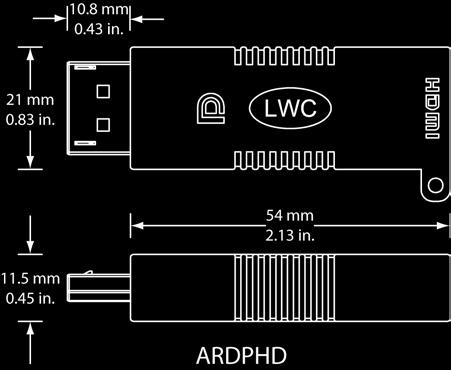
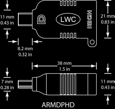
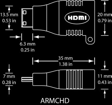
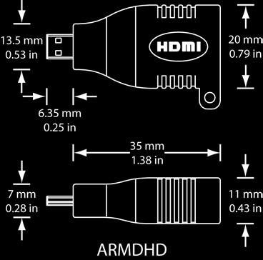
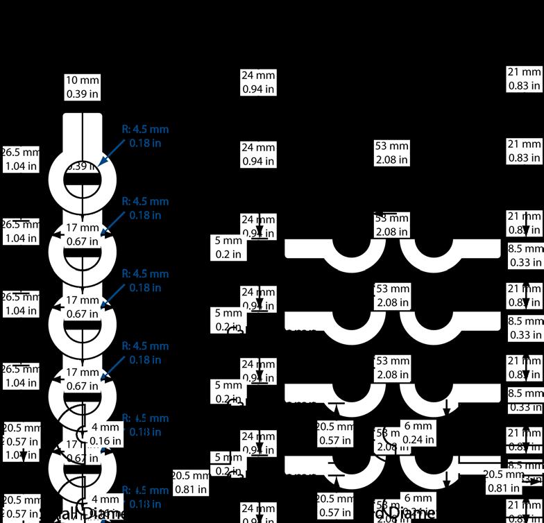
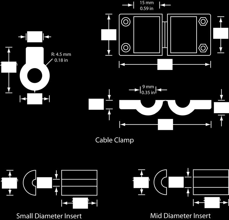
1 DL-AR2 Technical Specifications Universal HDMI Adapter Ring Rev The DL-AR2 Digital Adapter Keychain was developed to support the rising proliferation of mobile devices used in presentation systems. Most presentation infrastructures only support one or two input formats, usually HDMI for Digital and VGA for Analog. This product permits the presenter easy access to the appropriate adapter for connection to the HDMI infrastructure. Laptops, tablets, smart phones, digital cameras, and net books all have varying connections to display their content. This simple and effective ring of adapters permits the owner of the infrastructure to support mobile device content and keep the adapters secure and in place for the next presenter. The full DL-AR2 unit includes the following adapters in the basic format: (1) DisplayPort male to HDMI female, (1) Mini-DisplayPort male to HDMI female, (1) Mini-HDMI C male to HDMI female, and (1) Micro-HDMI D to HDMI female. The adapters are molded with a very strong eyelet that attach to the aircraft-grade steel cable. The main clamp is ABS and it can connect to HDMI cables up to 11mm in diameter. Two sets of foam rubber inserts for differing cable sizes are included. The security features of the ring are two staged. The clamp cannot be opened or installed without a Torx T10 Pin driver. This security screw has the raised pin in the center of the star to prevent standard Torx drivers from use. Inside the clamp is a second security feature, a steel ring with a 1.5mm hex set screw that locks the ends of the cables together. The unit is shipped with four Torx Pin screws and nuts. Two are extra in case of loss. Liberty item T10PD is a simple tool kit of a T10 pin driver and a 1.5mm hex wrench. The T10PD is sold separately.

2
3
4 DisplayPort Adapter (ARDPHD) Mini DisplayPort Adapter (ARMDPHD) Mini HDMI Adapter (ARMCHD) Micro HDMI Adapter (ARMDHD) Cable and Clamp Assembly (DL-CL) Security Cable Material Security Cable Length Cable Clamp Dimensions (closed) Cable Clamp Inner Diameter Cable Clamp Material Mid Insert Diameter Small Insert Diameter Mid, Small Insert Material Other Warranty Included Accessories Optional Toolkit Technical Specifications Male full size DisplayPort connector DisplayPort 1.1 for 1.62 and 2.7 Gbps Male mini DisplayPort connector DisplayPort 1.1 for 1.62 and 2.7 Gbps Male mini HDMI type C connector Male micro HDMI type D connector Steel with black polyethylene sheath 450 mm (17.72 in) 17 mm x 24 mm x 26.5 mm (0.67 in x 0.94 in x 1.04 in.) 9 mm (0.35 in.) Black ABS plastic 6 mm (0.24 in.) 4 mm (0.16 in.) Foam rubber 2 years Four T-10 screws, Four M3 nuts, one retaining ring, one 1.5 mm hex retaining screw T10PD
 comes with the 5")


 PATENT PENDING UNIVERSAL HDMI ADAPTER RING STEP-BY-STEP INSTRUCTIONS FIVE")


5 TWO FOAM INSERTS FOR HDMI CABLES COUPLER TWO SETS OF NUTS & SCREWS HDMI CABLE CLAMP TENSILE AIRCRAFT STRENGTH SECURITY RING The complete assembly (DL-AR) comes with the 5 most popular display adapters used in presentations. Adapters are also available separately so that you can create your own custom assembly! (HDMI CABLE SOLD SEPARATELY) Note: You will need a Torx T-10 Pin Driver and a 1.5mm Hex Key wrench to install and/or modify the DL-AR. Liberty tool kit T10PD contains both tools. T-10 TORX PIN DRIVER & 1.5MM HEX KEY WRENCH TOOL KIT T10PD If you are changing out any of the adapters, remove the coupler to open the security ring. Ensure the adapters you want are loaded on the security ring. a. The security ring coupler has a 1.5mm hex set screw holding the two ends of the security cable locked together. 2) PATENT PENDING UNIVERSAL HDMI ADAPTER RING STEP-BY-STEP INSTRUCTIONS FIVE PRESENTATION ADAPTERS 1) DL-AR b. Loosen and back out the set screw to release the cable c. Replace, remove or add adapters as needed for your particular configuration d. Feed the security ring back into the coupler. Ring ends can overlap. Determine the diameter size of the HDMI cable you are using and place the correct foam inserts into the clamp. Several HDMI cable options are available at Smallest Foam insert is for Micro cables 5mm or less in diameter Large Foam insert is for most standard cables up to 9mm in diameter No insert needed for really large HDMI cables above 9mm in diameter e. Tighten set screw in coupler to secure your adapters and hold the ring together. For more info on the adapters and ordering info, go to or scan the code to go directly to the DL-AR web page. SCAN QR CODE FOR MORE INFO


 A helpful hint is to bend the two exiting wires")


6 DL-AR PATENT PENDING 3) 4) Position the Cable Clamp onto the HDMI cable and close shut with your fingers. Position the Cable Clamp so you can feed the HDMI cable into the ends of the adapters comfortably without stressing the connection. Usually this is within 2-3 inches of the end of the HDMI connector molding. UNIVERSAL HDMI ADAPTER RING STEP-BY-STEP INSTRUCTIONS (Continued From Other Side) a. Position the coupler into the space between the two molded screw holes. b) A helpful hint is to bend the two exiting wires straight down; this will enable correct positioning of the wire clamp into the cable clamp cavity. Secure the nuts and screws in the clamp to hold the HDMI cable to the security loop. A looser insert can be used if you want your cable to slide, permitting it to be placed away when using HDMI only. a. Place the nuts into the hex shaped holes. b. Holding them in place with your finger, turn clamp over and then place the Torx screws into the holes and tighten down with the Torx Pin Driver. The DL-AR assembly is now ready for use! The HDMI cable will stay connected to the security ring, and the variety of adapters for the next presenter will stay put and never get lost or go missing. More adapters are in development! Connect for all the latest updates
AUDIO ROOF KIT P/N , , APPLICATION BEFORE YOU BEGIN KIT CONTENTS. Instr Rev Page 1 of 6
 AUDIO ROOF KIT P/N 2882064, 2882065, 2882066 APPLICATION Verify accessory fitment at Polaris.com. BEFORE YOU BEGIN Read these instructions and check to be sure all parts and tools are accounted for. Please
FOSC-600 C and D I N S T A L L A T I O N I N S T R U C T I O N
 FOSC-600 C and D I N S T A L L A T I O N I N S T R U C T I O N In-line and butt version Cold applied re-usable fiber optic closure Contents 1 Introduction 1.1 Product description 1.2 Capacity 2 General
FIST-GCOG2-Dx6. Follow all local safety regulations related to optical fiber plant elements.
 FIST-GCOG2 I N S T A L L A T I O N I N S T R U C T I O N TC-986-IP Rev A, Mar 2017 www.commscope.com FIST-GCOG2-Dx6 Content 1 Introduction 2 General 2.1 Abbreviations 2.2 Kit contents 2.3 Tools 2.4 Accessories
TeamWork Installation Guide
 C G G 00-0V/ A MAX TX RX +V APARATUS US 0 TeamWork Installation Guide TeamWork TeamWork is a fully customizable collaboration system comprised of an switcher, Show Me cables, a control processor, and a
2000i. Projector Replacement Guide. for Projector Replacement Kits. NEC MT1060R ( ) and NEC MT860R ( ) Interactive Whiteboard
 and NEC MT860R ( ) Interactive Whiteboard") 2000i Interactive Whiteboard Projector Replacement Guide for Projector Replacement Kits NEC MT1060R (03-00043) and NEC MT860R (03-00041) 99-00496-00 Rev A0 FCC Warning This equipment has been tested and
2000i Interactive Whiteboard Projector Replacement Guide for Projector Replacement Kits NEC MT1060R (03-00043) and NEC MT860R (03-00041) 99-00496-00 Rev A0 FCC Warning This equipment has been tested and
SLiC Fiber Aerial Closure System
 3 SLiC Fiber Aerial Closure System SLFC 533-SP SLFC 533-TS SLFC 733-SP Instructions May 2005 78-8135-4502-3-B N C H E S R A N G E M IL L IM E T E R S.4 10.6.8 A B C 15 20 I 1.0 Kit Contents Note: Examine
THE $1,000 HUDDLE ROOM Deploy a Display Deploy Liberty, DONE!
 THE $1,000 HUDDLE ROOM Deploy a Display Deploy Liberty, DONE! Total RETAIL price under $1,000! Huddle Rooms are one of the more popular trends in corporate AV. Wainhouse Research puts the market potential
TeamWork Kits Installation Guide
 TX 0 RX COM +5V APARATUS US TeamWork Kits Installation Guide TeamWork 400 and TeamWork 600 Kits The TeamWork 400 and TeamWork 600 kits consist of an HDMI switcher, system controller, Cable Cubby, and cables
FOSC 450 C6 and D6 Closures
 FOSC 450 C6 and D6 Closures I N S T A L L A T I O N I N S T R U C T I O N Fiber Optic Splice Closure 1. General Product Information The FOSC 450 C6 and D6 fiber optic splice closures use compressed gel
Cellular Signal Booster
 Drive 4G-X Cellular Signal Booster THE ALUMINUM CASING OF YOUR SIGNAL BOOSTER!! WILL ADJUST TO THE TEMPERATURE OF ITS ENVIRONMENT, BUT IS DESIGNED TO PROTECT THE SIGNAL BOOSTER TECHNOLOGY. FOR EXAMPLE,
HCS - HES Cabling Systems
 HCS - HES Cabling Systems Installation Manual for HCS High-Capacity Fiber-Optic Rack-Mount Cabinets Be sure to read and completely understand this procedure before applying product. Be sure to select the
REQUIRED TOOLS. Wire cutters Razor blade Soldering iron Pliers 11/16 Wrench for Tube 18mm Wrench for Ring
 S9122 PWS BNC MALE CABLE MOUNT COMPRESSION CONNECTOR S9022 PWS N TYPE MALE CABLE MOUNT COMPRESSION CONNECTOR S9322 PWS TNC MALE CABLE MOUNT COMPRESSION CONNECTOR The PWS S9122 is a BNC male cable mount
Service Parts Diagrams. For Model: 10/20/09 Service Parts Diagrams for the Rear Projection SMART Board 3000i-DV Interactive Whiteboard 1
 Service Parts Diagrams For Model: 000i-DV with the serial NEC MT060 numbers Serial greater numbers than 000 000i-DV-09000 to 0999 0/0/09 Service Parts Diagrams for the Rear Projection SMART Board 000i-DV
2100, 2200, 4100, 6200, MPB Series Side Mount Drive Package for Light Load 60 Hz Gearmotors
 00, 00, 400, 600, MPB Series Side Mount Drive Package for Light Load 60 Hz Gearmotors Installation, Maintenance & Parts Manual DORNER MFG. CORP. INSIDE THE USA OUTSIDE THE USA P.O. Box 0 975 Cottonwood
Gel-sealed in-line fiber optic closure
 SCIL-C Gel donut INSTALLATION INSTRUCTION TC-1363-1-IP Rev A, Oct 2017 www.commscope.com Gel-sealed in-line fiber optic closure Contents 1 General 2 Sizing and product kit information 3 Installation conditions
Ultra-Grip 2 Crimp Connector Hand Tool Kit for Coaxial Cable Connectors, Powerpole Connectors, Insulated and Non-Insulated Crimp Terminals
 Ultra-Grip 2 Crimp Connector Hand Tool Kit for Coaxial Cable Connectors, Powerpole Connectors, Insulated and Non-Insulated Crimp Terminals DXE-UT-KIT-CRMP2 DXE-UT-KIT-CRMP-INS-Revision 0a DX Engineering
Medium Box for Cable Termination
 FIST-MB2-T I N S T A L L A T I O N I N S T R U C T I O N Medium Box for Cable Termination Contents 1 Introduction 1.1 Product description. 2 General 2.1 Tools 2.2 Kit contents 3 Installation and pre assembling
Direct-Connect DVI Cables
 Direct-Connect DVI Cables Shielded for maximum EMI/RFI protection Dual-link resolutions/bandwidth up to 2560 x 1600 / 9.9 Gbps Single-link resolutions/bandwidth up to 1920 x 1080 / 4.95 Gbps P560-xxx Series
FIST-MB2-S. FIST Medium Box for Cable Splicing Only. 4 Cable installation. 1 Introduction. Contents. 2 General. 5. Fiber routing to individual trays
 FIST-MB2-S I N S T A L L A T I O N I N S T R U C T I O N FIST Medium Box for Cable Splicing Only Contents 1 Introduction 1.1 Product description 2 General 2.1 Tools 2.2 Kit contents 3 Installation and
Ultra-Grip Crimp Connector Hand Tool Kit for Coaxial Cable and Powerpole Connectors
 Ultra-Grip Crimp Connector Hand Tool Kit for Coaxial Cable and Powerpole Connectors DXE-UT-KIT-CRIMP DXE-UT-KIT-CRIMP-INS-Revision 2b DX Engineering 2014 1200 Southeast Ave - Tallmadge, OH 44278 USA Phone:
LWX-1. Satellite Weather Radio Module Installation Instructions A
 LWX-1 Satellite Weather Radio Module Installation Instructions 988-0158-13A Copyright 2009 Navico All rights reserved. No part of this manual may be copied, reproduced, republished, transmitted or distributed
All-In-One. Connector System PODIUMS AUDITORIUMS FLY PACKS MOBILE - TRUCKS PANELS CORPORATE FLOOR POCKETS RENTAL & STAGING RACKS
 DATA 2 CONTROL 1 A 5 B 6 C 7 8 9 G 13 J 15 L 19 P All-In-One E 10 16 M 20 R Connector System F 11 12 H K 17 14 18 N 21 22 T 26 PODIUMS AUDITORIUMS FLY PACKS VIDEO 4 AUDIO 3 D MOBILE - TRUCKS PANELS CORPORATE
Instruction manual. KUZMA 4POINT 14 inch TONEARM Serial Number:
 Instruction manual KUZMA 4POINT 14 inch TONEARM Serial Number:.. 2016-09 1 KUZMA LTD INSTRUCTION MANUAL FOR 4POINT 14 tonearm The 4POINT 14 tonearm is a very precisely engineered piece of equipment, however,
TECHNICAL GUIDE. TOUGH GUN ThruArm G1 Series Robotic MIG Guns for Motoman Robots EA1400N, EA1900N and SSA2000
 TECHNICAL GUIDE TOUGH GUN ThruArm G1 Series Robotic MIG Guns for Motoman Robots EA1400N, EA1900N and SSA2000 INSTALLATION MAINTENANCE TECHNICAL DATA OPTIONS EXPLODED VIEW & PARTS LIST ORDERING INFORMATION
INSTALLATION INSTRUCTIONS
 INSTALLATION INSTRUCTIONS PARTS REQUIRED Parts in the box Single monitor Dual monitor M2 M8 M/Flex + (package contents will depend on configuration ordered) Tools required for installation 6.0 mm Hex Key
Installing a Wire Mesh Pulling Grip on All-Dielectric DX Armored Fiber Optic Cables
 revision history Issue Date Reason for Change Related literature SRP-004-136 Accessing All-Dielectric DX Armored Fiber Optic Cables Admonishments 1. General This procedure provides instructions for installing
ASSEMBLY, INSTALLATION, AND REMOVAL OF CONTACTS AND MODULES
 ASSEMBLY, INSTALLATION, AND REMOVAL OF CONTACTS AND MODULES FOR 75 OHM AND 75 OHM HD COAXIAL CONTACTS AND MODULES Table of Contents SECTION 1 RECEIVER CONTACT ASSEMBLY INSTRUCTIONS SECTION 2 ITA CONTACT
KRAMER ELECTRONICS LTD. USER MANUAL MODEL: RTBUS-12 Round Table Connection Bus. P/N: Rev 1
 KRAMER ELECTRONICS LTD. USER MANUAL MODEL: RTBUS-12 Round Table Connection Bus P/N: 2900-300099 Rev 1 Contents 1 Introduction 1 2 Getting Started 2 2.1 Achieving the Best Performance 2 3 Overview 3 3.1
Optical Distribution Box 300 Installation Guide. Version : R0.0
 Optical Distribution Box 300 Installation Guide Document No. : OD16-546-L-01 Version : R0.0 Date: 21-Mar-2018 IMPORTANT INSTRUCTIONS When using fiber optic equipment, basic precautions should always be
Troubleshooting Guide 9630 Series
 Troubleshooting Guide 9630 Series Satellite Solutions for Mobile Markets 11200 Hampshire Avenue South, Bloomington, MN 55438-2453 Phone: (800) 982-9920 Fax: (952) 922-8424 www.kingcontrols.com 1305-SEMI
3 SLiC Aerial Closure with Rubber End Seal
 3 Aerial Closure with Rubber End Seal Instructions 1.0 General 1.1 This instruction bulletin describes the assembly of the 3M Aerial Closure with external bonding hanger brackets. These closures are suitable
8753E, 8753ET, and 8753ES Network Analyzer Option 1D5 High Stability Frequency Reference Upgrade Kit. Applicable Upgrade Kit Model Number
 Installation Note 8753E, 8753ET, and 8753ES Network Analyzer Option 1D5 High Stability Frequency Reference Upgrade Kit Network Analyzer Model Number 8753E 8753ET 8753ES Applicable Upgrade Kit Model Number
MODULAR A/V CABLING SOLUTIONS MODULAR A/V CABLING SOLUTIONS
 RapidRun is the most complete audio/video cabling system built to save installation time, accommodate changes, and reduce the likelihood of return service calls due to faulty field terminations. RapidRun
TECHNICAL GUIDE. TOUGH GUN ThruArm Series Robotic MIG Guns for MOTOMAN EA1400N, EA 1900N and SSA2000 Robots
 TECHNICAL GUIDE TOUGH GUN ThruArm Series Robotic MIG Guns for MOTOMAN EA1400N, EA 1900N and SSA2000 Robots INSTALLATION MAINTENANCE TECHNICAL DATA OPTIONS EXPLODED VIEW & PARTS LIST ORDERING INFORMATION
3. Electronics and MMU2 unit assembly
 Written By: Jakub Dolezal 2018 manual.prusa3d.com/ Page 1 of 34 Step 1 Tools necessary for this chapter Please prepare tools for this chapter: 2.5mm Allen key for M3 screws 2mm Allen key for nut alignment
2100/2200/4100/6200 & MPB Series Bottom Mount Drive Pack. for Standard Load Parallel Shaft 60 Hz Gearmotors
 00/00/400/600 & MPB Series Bottom Mount Drive Pack. for Standard Load Parallel Shaft 60 Hz Gearmotors Installation, Maintenance & Parts Manual DORNER MFG. CORP. INSIDE THE USA OUTSIDE THE USA P.O. Box
M2 Antenna Systems, Inc. Model No: 23CM35
 M2 Antenna Systems, Inc. Model No: 23CM35 SPECIFICATIONS: Model... 23CM35 Frequency Range... 1250 To 1300 MHz *Gain... 20.94 dbi Front to back... 25 db Typical Beamwidth... E=17 H=18 Feed type... Folded
2178-L/S Series Fiber Optic Splice Case with Gasket
 2178-L/S Series Fiber Optic Splice Case with Gasket Instructions for: 2178-S Splice Case 2178-LS Splice Case 2178-LL Splice Case 2181-LS Cable Addition Kit May 1997 34-7041-9949-5-A 1 Table of Contents
CONNECTING THE FUTURE 19" LINXS LIGHTWAVE INTEGRATED CROSS-CONNECT SYSTEM USER MANUAL
 CONNECTING THE FUTURE 19" LINXS LIGHTWVE INTEGRTED CROSS-CONNECT SYSTEM USER MNUL 109003 Issue Rev 2 19" Lightwave Integrated Cross-Connect System (LINXS) User Manual Document Number 109003 Issue Rev 2
Coyote popup features
 Coyote popup features The Coyote popup display system combines strength, reliablility, and style in a lightweight and easy to use system. It is fully magnetic, making it simple to assemble and disassemble,
National Wire and Cable and National Cable Molding Headquarters Los Angeles California
 National Wire and Cable and National Cable Molding Headquarters Los Angeles California CAPABILITIES Medical Business Machines Communications Equipment Computer Equipment Audio Systems General Instrumentation
INSTRUCTION MANUAL. H4 PV Cable Connector Series Dual Approval (UL+IEC/TUV)
") H4 PV Cable Connector Series Dual Approval (UL+IEC/TUV) REVISION RECORD REV DESCRIPTION DATE A FIRST RELEASE July/28/2011 B IMPROVED LAYOUT Sep/6/2011 C UPDATE TORQUE Nov/3/2011 D UPDATE THE S&F REQUIREMENT
H4 PV Cable Connector Series Dual Approval (UL+IEC/TUV) REVISION RECORD REV DESCRIPTION DATE A FIRST RELEASE July/28/2011 B IMPROVED LAYOUT Sep/6/2011 C UPDATE TORQUE Nov/3/2011 D UPDATE THE S&F REQUIREMENT
Bionic Elephant Trunk. Assembly Instructions
 Bionic Elephant Trunk Assembly Instructions Equipment and Supplies Required items from the Bionics Kit and/or Materials Pack: 1. Tail fin (small) assembled 2 see Start Here for tail fin assembly instructions
Automatic Connector MHV Connectors MHV Introduction MHV series connectors Contents Polarized mating interfaces Anti-Rock mating interfaces
 Automatic s 2004 Automatic. All rights reserved. pdf 1.0 3-18-04 Contents Specifications........................... 2 Straight Cable Plugs...................... 3 Right Angle Cable Plugs...................
Aerospace Fiber Optics
 Aerospace Fiber Optics AFO 101, Session 2 Fiber Optic Assembly Everett Community College. All rights reserved. 1 Session Learning Objectives After completing this session you should be able to: Work safely
Unipole and Multipole Connectors
 Unipole and Multipole Connectors Miniature Cylindrical Connectors With Push-Pull-Locking Shenzhen Medplus Connector Co.,Limited. 2 th Floor,Ming An Street,GongMing Town, Baoan District, Shenzhen, China
Operating Manual. Automated Gear. Apollo Design Technology, Inc Fourier Drive Fort Wayne, IN USA
 Operating Manual Automated Gear Apollo Design Technology, Inc. 4130 Fourier Drive Fort Wayne, IN 46818 USA PH: +01(260)497-9191 FX: +01(260)497-9192 www.apollodesign.net 11-25-09 5-6 POWERING UP THE RIGHT
Distributed Design Series
 D10SUB 10-INCH FEATURES Powerful, high-impact bass response Internal passive low-pass crossover Spring loaded Drop-Stop installation assistant tabs support the back can on the included rails and C-ring
24-Fiber LANLINXS (Model # ) 48-Fiber LANLINXS (Model # ) User Manual
 48-Fiber LANLINXS (Model # ) User Manual") 24-Fiber LANLINXS (Model # 055-8632-5000) 48-Fiber LANLINXS (Model # 055-8832-5000) User Manual 24-Fiber LANLINXS (Model # 055-8632-5000) 48-Fiber LANLINXS (Model # 055-8832-5000) User Manual, Part Number
24-Fiber LANLINXS (Model # 055-8632-5000) 48-Fiber LANLINXS (Model # 055-8832-5000) User Manual 24-Fiber LANLINXS (Model # 055-8632-5000) 48-Fiber LANLINXS (Model # 055-8832-5000) User Manual, Part Number
CANNON STANDARD page 1 of 18. Cm5 MOTOR CONNECTOR
 CANNON STANDARD page 1 of 18 1 General Information... 2 1.1 Scope... 2 2 Ordering Code... 3 2.1 Housing / Motor Side... 3 2.2 Cable Side... 3 3 Explosion Drawing... 3.1 Explosion Complete Assembly... 3.2
2178 Fiber Optic Splice Case and 2181 Cable Addition Kit
 2178 Fiber Optic Splice Case and 2181 Cable Addition Kit Instructions January 1994 Issue 1, 34-7029-6387-6 1 2 Contents: 1.0 General... 4 2.0 Specifications... 4 3.0 Kit Contents... 5 SECTION 1: 2178 Splice
3M Distribution Box (DDB)
") 3M Distribution Box (DDB) Merged Copper and Fiber Pole/Post Mount Enclosure Installation Instructions November 2015 78-0015-2736-1-A 2 November 2015 78-0015-2736-1-A Contents 1.0 General 2.0 Enclosure
3M Distribution Box (DDB) Merged Copper and Fiber Pole/Post Mount Enclosure Installation Instructions November 2015 78-0015-2736-1-A 2 November 2015 78-0015-2736-1-A Contents 1.0 General 2.0 Enclosure
Keysight Noise Figure Measurement Capability Upgrade Kit
 Keysight Noise Figure Measurement Capability Upgrade Kit To Upgrade PNA-X N5244A or N5245A with Option 423, N5244B Option 422 or Option 423, N5245B Option 422 or Option 423 to include Option 029 Upgrade
3M Pressurized Closure System 2-Type 505
 Communication Markets Division 3M Pressurized Closure System 2-Type 505 The 3M Pressurized Closure System 2-Type 505 is a complete, pressuretight, re-enterable closure system for enclosing spliced connections
E4200 Antenna Installation Instructions: 1. Soldering required (here is the list of tools you will need)
") Thank you for purchasing the 6 Antenna Mod Kit for your Linksys router. First we will show you how to install the antennas for your router. Next we will teach you how to setup the DD-WRT firmware which
Thank you for purchasing the 6 Antenna Mod Kit for your Linksys router. First we will show you how to install the antennas for your router. Next we will teach you how to setup the DD-WRT firmware which
Installation instructions, accessories. Subwoofer. Volvo Car Corporation Gothenburg, Sweden. Page 1 / 29
 Installation instructions, accessories Instruction No 30752136 Version 1.1 Part. No. 30752135 Subwoofer Volvo Car Corporation Subwoofer- 30752136 - V1.1 Page 1 / 29 Equipment A0000162 A0000161 A0801178
OFDC-B8-72. Outdoor fiber distribution closure. 6 Closing. Content 1 Introduction. 7 Re-entry. 2 Kit content. 3 Closure preparation
 OFDC-B8-72 I N S T A L L A T I O N I N S T R U C T I O N Outdoor fiber distribution closure Content 1 Introduction 2 Kit content 3 Closure preparation 4 Cable preparation 4.1 Feeder cable 4.2 Drop cable
Ultra-Grip 2 Crimp Connector Hand Tool Kit for Crimp Coaxial Cable Connectors, Powerpole Connectors, Insulated and Non-Insulated Crimp Terminals
 Ultra-Grip 2 Crimp Connector Hand Tool Kit for Crimp Coaxial Cable Connectors, Powerpole Connectors, Insulated and Non-Insulated Crimp Terminals DXE-UT-KIT-CRMP2 DXE-UT-KIT-CRMP-INS-Revision 0d DX Engineering
3 Closure preparation 3.1 Work-stand 3.2. Opening FIST-GCOG2-Dx Preparing drop cable with micro-tubes
 FIST-GCOG2-Dx24 I N S T A L L A T I O N I N S T R U C T I O N FTTH closure for micro-tubes and micro-cables Content 1 Introduction 2 Kit content 3 Closure preparation 3.1 Work-stand 3.2. Opening FIST-GCOG2-Dx24
Vibratory Deck Sieves 15 in. (380 mm)
") Instruction Sheet P/N 1604433-01 Vibratory Deck Sieves 15 in. (380 mm) Introduction This instruction sheet covers the vibratory deck sieves listed in the following tables. 15-Inch Deck Sieves with 2.5
Instruction Sheet P/N 1604433-01 Vibratory Deck Sieves 15 in. (380 mm) Introduction This instruction sheet covers the vibratory deck sieves listed in the following tables. 15-Inch Deck Sieves with 2.5
Instructions. Cable with Armor F CAUTION. October Rev A
 3M Single Conductor Accessory Breakout Kits (BOK's) for use with 3M Cable Accessories (Terminations, T-Bodies and Push-On Elbows) For Use With Single Conductor Accessories On Three-Core Conductor Cables
IP-LINX. Installation Guide
 Installation Guide Installation Guide, 146653-4 Copyright 2017, Telect, Inc. All Rights Reserved Telect and Connecting the Future are registered trademarks of Telect, Inc. 22425 East Appleway Ave. # 11
General Wiring and Installation Guidelines. Typical Mounting Installations Electrical Connections General Guidelines Common Questions & Answers
 General Wiring and Installation Guidelines Typical Mounting Installations Electrical Connections General Guidelines Common Questions & Answers Congratulations on your purchase of a Dynapar brand encoder.
3M Scotchcast Reenterable Signal and Control Cable Splicing Kits 78-R Series
 3M Scotchcast Reenterable Signal and Control Cable Splicing Kits 78-R Series Instructions Voltage Rating: 1000 V, Temperature Rating: 90 C Kit Contents 78-R1 78-R2 78-R3 78-R4 78-R5 Sleeve Set 1 1 1 1
Connecting an Intel based Macintosh laptop to a TV
 Connecting an Intel based Macintosh laptop to a TV Scenario 1: TV has a PC input on it 1. Look for the VGA connector on the back of your TV. It may also be labeled PC or RGB. 2. Make sure you have the
NewScope-7A Operating Manual
 2016 SIMMCONN Labs, LLC All rights reserved NewScope-7A Operating Manual Preliminary May 13, 2017 NewScope-7A Operating Manual 1 Introduction... 3 1.1 Kit compatibility... 3 2 Initial Inspection... 3 3
Satellite Dish Installation Manual (Ver. 2) 1
 1") Satellite Dish Installation Manual Provided by DiscoverNet, Inc. Satellite Dish Installation Manual (Ver. 2) 1 Table of Contents Section 1: Introduction Page 3 Section 2: Recommended Tools and Materials
Satellite Dish Installation Manual Provided by DiscoverNet, Inc. Satellite Dish Installation Manual (Ver. 2) 1 Table of Contents Section 1: Introduction Page 3 Section 2: Recommended Tools and Materials
Safety Rules Parts Check Lists and Photos Cable Diagrams for Various Crane Configurations Step by Step Instructions Tips for Packaging and Storage
 EZ CRANE USER MANUAL INCLUDED INSIDE Safety Rules Parts Check Lists and Photos Cable Diagrams for Various Crane Configurations Step by Step Instructions Tips for Packaging and Storage WATCH THE INSTRUCTIONAL
Check what you have received against the component checklist and hardware above.
 SSS SSPW SSW SSPB SSB Component Checklist Installation Instructions SYSTEMA Systema Monitor Spring Arm HARDWARE Display Mounting Spacers (x4) 3/4mm Allen Keys Display Mounting Screws M4 x 14mm (x1) Silver
NC-1000 INSTALLATION MANUAL NC-1000 FIBRE OPTIC CROSS-CONNECTION SYSTEM
 NC-1000 INSTALLATION MANUAL NC-1000 FIBRE OPTIC CROSS-CONNECTION SYSTEM Content 1. General 5 2. The products of NC-1000 system 6 3. Mounting of the frame 8 4. Earthing of the frame 8 NC-1000 FIBRE OPTIC
MP Maker Pro Mk.1. Quick Start Guide
 MP Maker Pro Mk.1 P/N 33013 Quick Start Guide ONLINE SUPPORT Monoprice is pleased to provide free online support. For order related issues, contact the Customer Service department through the Live Chat
Assembly Instructions
 Assembly Instructions REP Series Environmentally - Sealed Rectangular Plastic Connectors Hypertac S.A. January 2014 Assembly Instructions REP Series January 2014 1 Table of Contents I. Introduction A.
18mm ECAM Cable Entry Port
 18mm ECAM Cable Entry Port Instructions October 2006 1.0 Introduction The 3M 18mm ECAM (External Cable Assembly Module) Cable Entry Port Kit is designed to accept fiber optic cables with external diameters
Turret Replacement Instruction Manual
 Automatic Multi-Satellite TV Antenna Turret Replacement Instruction Manual for models RPSKLGL, RPSKSML, SK-LG00, SK-SM00, & RP-SWM For help, email help@winegard.com or call -800-788-7 568 Raising the Antenna
Kramer Electronics, Ltd. USER MANUAL. Wall Plate Models: SV-301 SV-302 SV-303 SV-304 SV-305
 Kramer Electronics, Ltd. USER MANUAL Wall Plate Models: SV-301 SV-302 SV-303 SV-304 SV-305 Contents Contents 1 Introduction 1 2 Getting Started 1 3 Overview 2 4 Defining the Wall Plates (for the United
CSM Color sensors. Color sensors for the detection of a single color in restricted space conditions
 CSM Color sensors Color sensors for the detection of a single color in restricted space conditions Due to its compact design, the CSM can be used in the most confined of spaces. The choice of color tolerance
TECHNICAL GUIDE. TOUGH GUN ThruArm G1 Series Robotic MIG Guns for FANUC Robots 100iC, 100iC-12, 100iC-6L, 100iC-7L, 120iC, 120iC-10L, 120iC-12L
 TECHNICAL GUIDE TOUGH GUN ThruArm G1 Series Robotic MIG Guns for FANUC Robots 100iC, 100iC-12, 100iC-6L, 100iC-7L, 120iC, 120iC-10L, 120iC-12L INSTALLATION MAINTENANCE TECHNICAL DATA OPTIONS EXPLODED VIEW
Assembling and Mounting the Presentation Display, Speakers, Speaker Screens, and Table Door
 CHAPTER 8 Assembling and Mounting the Presentation Display, Speakers, Speaker Screens, and Table Door July 13, 2012, This document provides you with the procedures you perform to assemble and mount the
Crimp & Cleave Termination Instructions for SEL ST Connectors
 Your Optical Fiber Solutions Partner Crimp & Cleave Termination Instructions for SEL ST Connectors For Use With: ST Termination Kit (SEL, Part Number BT05402-01) 200 µm HCS Fiber-Optic Cable ST Crimp &
TracVision 95W LNB Installation
 TracVision 95W LNB Installation To enable a TracVision system to receive DIRECTV international programming from the linear satellite located at 95W, a 95W LNB must be installed in a secondary M7SK or M9
KUZMA 4POINT TONEARM
 KUZMA 4POINT TONEARM Instruction manual 2008-6 Serial Number:.. 1 KUZMA LTD INSTRUCTION MANUAL FOR 4POINT tonearm The 4POINT tonearm is a very precisely engineered piece of equipment, however, the construction
Look No Further... Materials & Finishes. Specifically made for all your: Gigabit Ethernet, HDMI, USB 2.0/3.0 Needs! onnectors
 1 Look No Further... Specifically made for all your: Gigabit Ethernet, HDMI, US 2.0/3.0 Needs! Amphenol Aerospace now offers a connector series that can be used for all of your multi-media needs. This
Main Products. Cable Assemblies Wire Harnesses Raw Cables. Connectors
 About BMA BMA technology Ltd was found in Hong Kong in 2009. Our factory is located in Guangdong, China. With the 10,000m 2 production area, we are able to hold 500 workers during the peak season. Our
Lynx Broadband Installation Manual for Residential Packages with a 35 db Amp Quick Start Guide (first 3 pages)
") Lynx Broadband Installation Manual for Residential Packages with a 35 db Amp Quick Start Guide (first 3 pages) 1. Be sure that your kit includes all the parts shown in the Check the Equipment section in
Lynx Broadband Installation Manual for Residential Packages with a 35 db Amp Quick Start Guide (first 3 pages) 1. Be sure that your kit includes all the parts shown in the Check the Equipment section in
lumenalpha spot Specification Sheet
 Client Project name Order# Type Qty FEATURES AND BENEFITS Physical Housing material: extruded aluminum Available in or 8 sections Finish: black or white Ceiling mounting: surface or recessed Wall mounting:
Fiber Optic Splice Closure GPJ Instruction Manual
 Fiber Optic Splice Closure GPJ09-9401 Instruction Manual 1. Brief Introduction GPJ09-9401 type of Fiber Optic Splice Closure is a member in dome series, the main function is to provice direct pass, branch
HN Connectors. Automatic Connector. Introduction. Contents. 631/ FAX 631/
 Connectors Introduction 2004 Automatic Connector. All rights reserved. pdf 1.0 4-13-04 Contents Specifications........................... 2 Straight Cable Plugs...................... 3 Right Angle Cable
Channel Cable Tray - Accessories
 Splice Plate The Splice Plate has the standard 4-hole pattern for all cable channel. Provided with straight sections and fittings. 9(*)-1043 3 (76) 9(*)-1044 4 (101) 9(*)-1044-6 6 (152) Horizontal Adjustable
Industrial Monitor Update Kit
 Industrial Monitor Update Kit (Bulletin Number 6157) Installation Instructions 2 Table of Contents Table of Contents Industrial Monitor Update Kit... 3 Overview... 3 Part 1 - Initial Preparation... 5 Part
Optical. HDMI series NEW PRODUCTS 2019
 Optical HDMI series NEW PRODUCTS 2019 HDMI AT THE SPEED OF LIGHT HDMI 2.0 cables are great for transferring large amounts of data, therefore they are used in 4K@60Hz Ultra HD video applications like home
Service Parts Diagrams. For Model: SRS-LYNC-L-G5. (with SBID8065i-G5 display)
") Service Parts Diagrams SRS-LYNC-L-G5 For Model: (with SBID8065i-G5 display) Service Parts Diagrams Revision History Revision - May, 05 New document Standard Warranty Terms Base product: Two-year limited
Service Parts Diagrams SRS-LYNC-L-G5 For Model: (with SBID8065i-G5 display) Service Parts Diagrams Revision History Revision - May, 05 New document Standard Warranty Terms Base product: Two-year limited
COYOTE CLOSURE FOR UNDERGROUND, AERIAL, AND BURIED SPLICES 6.0" x 22" 8.5" x 22" (15.24 cm x cm cm x cm)
") OCTOBER 2004 COYOTE CLOSURE FOR UNDERGROUND, AERIAL, AND BURIED SPLICES 6.0" x 22" 8.5" x 22" (15.24 cm x 55.88 cm 21.59 cm x 55.88 cm) Be sure to read and completely understand this procedure before applying
OCTOBER 2004 COYOTE CLOSURE FOR UNDERGROUND, AERIAL, AND BURIED SPLICES 6.0" x 22" 8.5" x 22" (15.24 cm x 55.88 cm 21.59 cm x 55.88 cm) Be sure to read and completely understand this procedure before applying
Control cabinet interface and cable entry systems
 Modlink MPV Control cabinet interface The Modlink MPV control cabinet interface provides the connection from the control cabinet to the fieldbus environment (outside) in a simple way. Durable connection
RAIL D-SUB BACKSHELLS
 RAIL D-SUB BACKSHELLS FOR D-SUBMINIATURE CONNECTORS D-SUB BACK SHELLS /// DATA SHEET RAIL D-SUB BACKSHELLS FOR D-SUBMINIATURE CONNECTORS TE Connectivity (TE) provide a comprehensive range of ruggedized
TECHNICAL GUIDE. TOUGH GUN ThruArm G1 Series Robotic MIG Guns for KUKA Robots KR 5 arc HW
 TECHNICAL GUIDE TOUGH GUN ThruArm G1 Series Robotic MIG Guns for KUKA Robots KR 5 arc HW Effective September 2010 QUICK LOAD Liners Standard on all TOUGH GUN Robotic MIG Guns INSTALLATION MAINTENANCE TECHNICAL
MCT Multi-Compression Tools
 MCT-101 Universal plunger tips support all connector types. 360-degree connector support ensures uniform compression and prevents misalignment. Efficient self-releasing dogs facilitate easy, one-handed
INSTALLATION INSTRUCTIONS
 INSTALLATION INSTRUCTIONS BEFORE INSTALLING OR ADJUSTING THIS PRODUCT, PLEASE READ THESE INSTRUCTIONS CAREFULLY. PLEASE KEEP THIS GUIDE FOR FUTURE REFERENCE FIBER OPTIC SWING-OUT PATCH PANEL INSTRUCTION
VT VGA TFT NEMA 4/12 Flat Panel Monitor. User s Guide
 VT1040 10.4 VGA TFT NEMA 4/12 Flat Panel Monitor User s Guide 301040(A) (was document no. 920A0001 version 1.1), revised 01/98 Viewtronix Viewtronix reserves the right to make changes in specifications
TECHNICAL GUIDE. TOUGH GUN ThruArm G2 Series Robotic MIG Guns for FANUC Robots 100iC, 100iC-6L, 120iC, 120iC-10L INSTALLATION MAINTENANCE
 TECHNICAL GUIDE TOUGH GUN ThruArm G2 Series Robotic MIG Guns for FANUC Robots 100iC, 100iC-6L, 120iC, 120iC-10L INSTALLATION MAINTENANCE TECHNICAL DATA OPTIONS EXPLODED VIEW & PARTS LIST ORDERING INFORMATION
MUK REAR PANEL ASSEMBLY ASSEMBLY INSTRUCTIONS
 Rev B. 13 August 2017 ASSEMBLY INSTRUCTIONS The Midnight Ultimate Keyer (MUK) consists of two functional assemblies: Rear Panel containing the interface and power connectors. Front Panel containing the