Expressive Motion Synthesis for Robot Actors in Robot Theatre
|
|
|
- Cory Patrick
- 6 years ago
- Views:
Transcription
1 Portland State University PDXScholar Dissertations and Theses Dissertations and Theses Expressive Motion Synthesis for Robot Actors in Robot Theatre Mathias I. Sunardi Portland State University Let us know how access to this document benefits you. Follow this and additional works at: Recommended Citation Sunardi, Mathias I., "Expressive Motion Synthesis for Robot Actors in Robot Theatre" (2010). Dissertations and Theses. Paper /etd.720 This Thesis is brought to you for free and open access. It has been accepted for inclusion in Dissertations and Theses by an authorized administrator of PDXScholar. For more information, please contact
2 Expressive Motion Synthesis for Robot Actors in Robot Theatre by Mathias I. Sunardi A thesis submitted in partial fulfillment of the requirements for the degree of Master of Science in Electrical and Computer Engineering Thesis Committee: Marek A. Perkowski, Chair Douglas V. Hall Xiaoyu Song Portland State University 2010
3 ABSTRACT Lately, personal and entertainment robotics are becoming more and more common. In this thesis, the application of entertainment robots in the context of a Robot Theatre is studied. Specifically, the thesis focuses on the synthesis of expressive movements or animations for the robot performers (Robot Actors). The novel paradigm emerged from computer animation is to represent the motion data as a set of signals. Thus, preprogrammed motion data can be quickly modified using common signal processing techniques such as multiresolution filtering and spectral analysis. However, manual adjustments of the filtering and spectral methods parameters, and good artistic skills are still required to obtain the desired expressions in the resulting animation. Music contains timing, timbre and rhythm information which humans can translate into affect, and express the affect through movement dynamics, such as in dancing. Music data is then assumed to contain affective information which can be expressed in the movements of a robot. In this thesis, music data is used as input signal to generate motion data (Dance) and to modify a sequence of pre-programmed motion data (Scenario) for a custom-made Lynxmotion robot and a KHR-1 robot, respectively. The music data in MIDI format is parsed for timing and melodic information, which are then mapped to joint angle values. Surveys were done to validate the usefulness and contribution of music signals to add expressiveness to the movements of a robot for the Robot Theatre application. i
4 Table of Contents ABSTRACT...i List of Tables...iv List of Figures...v Chapter 1 Introduction...1 Chapter 2 Related Works in Expressive Animations of Humanoid Robots Interactive Humanoid Robots Signal-based Animations Motion-driven Music Performing Arts Theories in Computer Animation...13 Chapter 3 Goals, Hypothesis, and Evaluation Methodology Goals Hypothesis Evaluation Methodology Measurement Issue...21 Chapter 4 Designing a Robot Actor for Robot Theatre Animation of a Robot Actor Experiment with Signal Processing Techniques for Creating Affective Robot Motion Experiment for Emotion and Attitude Identification in Dynamic (Moving) Gestures and Static Gestures (Poses) The Physical Design of a Robot Actor...32 Chapter 5 Design of The Melodic Motion System System Overview Input Sound Gesture Library Gesture Representation Gesture Transition Processes Sound Parsing First Stage XML to Beat-Indexed Python List The Second Stage Information Extraction Time Markers Timed Events Melodic Surface and Rests Information Extraction Summary Scenario Creation...81 ii
5 5.3.3 Free Mode Planning Scenario Execution (Scenario Mode) Gesture Mode Putting Everything Together Hardware ASC Kondo KHR-1 Humanoid Robot Custom Lynxmotion Robot Timing Motion Execution on ASC Chapter 6 Experiments The Experiments The Results Survey 1: Motion Generated from Music Data Timing Expressing the Music Overall Performance Preference The Results Survey 2: Scenario + Music Data Timing Expressions in the Scenario Overall Performance Preference Discussion / Result Summary Chapter 7 Contributions, Conclusions, and Future Works Contributions Conclusions Future Works REFERENCES Appendix A Dance Survey Form Appendix B Scenario Survey Form Appendix C Comments from Survey Participants on the Dance and Scenario Performances iii
6 List of Tables Table 5.1 Table 5.2 Table 5.3 Table 5.4 Table 5.5 Table 5.6 Table 5.7 Table 6.1 Time Markers result (first five time markers)...68 Example of generating Pos and Acc values for each note event...73 Constraints for the movements of the Lynxmotion robot...85 Generated motion data...86 Motion data mapped to Time Markers...86 KHR-1 servo assignment on ASC Custom Lynxmotion robot servo assignment on ASC KHR-1 Gestures iv
7 List of Figures Figure 2.1: Kismet...6 Figure 2.2: WE-4RII...7 Figure 2.3: The Public Anemone...8 Figure 2.4: icat...9 Figure 2.5: Perlin Noise...11 Figure 2.6: Animation of Luxo Jr...15 Figure 2.7: Kinesphere...16 Figure 4.1: Oscar...34 Figure 5.1: The block diagram of the proposed system...35 Figure 5.2: Transition Function...49 Figure 5.3: A snippet of the.med format...53 Figure 5.4: A sampled sound segment and the same segment looped...58 Figure 5.5: The looped sample from Figure 5.4 modulated with the ADSR envelope...59 Figure 5.6: Music information parsing stages...61 Figure 5.7: Excerpt of <event /> information from Figure Figure 5.8: Output of stage 1 of the Sound Parsing process...62 Figure 5.9: Structure of the output of Stage Figure 5.10: Stage 1 of the parsing process...64 Figure 5.11: Process to obtain the Time Markers list...66 Figure 5.12: Generating the acceleration and displacement values from note events...71 Figure 5.13: Melodic Surface information...77 Figure 5.14: Rest information...78 Figure 5.15: Melodic surface and rest information...79 Figure 5.16: Contents of the 'notes' attribute of the first melodic surface from the example in Figure Figure 5.17: Configuration of the custom Lynxmotion robot...84 Figure 5.18 Plot of generated motion data for a) Joint 1,4, b) Joint 2,3(from Table 5.5) of the Lynxmotion robot using MIDI data shown in Figure Figure 5.19: Applying Time Markers and Timed Events to Scenario data...88 Figure 5.20: Process of mapping Scenario data with music timing and transformation data...90 Figure 5.21: The effect of one music data to the Scenario data of one joint...93 Figure 5.22: Modified Scenario data is mapped to time markers (in seconds)...94 Figure 5.23: The complete system...95 Figure 5.24: The ASC16 servo controller board...97 Figure 5.25: Kondo KHR-1 humanoid robot...99 Figure 5.26: RCB-1 string format to send servo positions manually Figure 5.27: The custom Lynxmotion robot Figure 5.28: Timed execution of commands/motion data Figure 6.1: Survey 1 Timing results Figure 6.2: Survey 1 Expressiveness results v
8 Figure 6.3: The Lynxmotion robot pose dancing to Mozart Sonata No Figure 6.4: Survey 1 Overall performance results Figure 6.5: Survey 1 Participants' preference Figure 6.6: Survey 2 Timing performance results Figure 6.7: Survey 2 Expression performance results Figure 6.8: Survey 2 Overall performance results Figure 6.9: Survey 2 Participants' preference Figure 6.10: Average performance scores for each robot in the Dance survey (Survey 1) Figure 6.11: Average performance scores for each robot in the Scenario survey (Survey 2) vi
9 Chapter 1 Introduction There is a growing number of researches on humanoid robots. Many groups have developed highly articulated humanoid robots for research [1], [2], [3], [4], [5], and many companies developed small humanoid robots for hobbyists like KHR-1, Bioloid, isobot, RoboSapien, and Robonova. The research topics on humanoid robots ranges from the bipedal walking, running [1], [2] dextrous object manipulation using human-like hands [4], behavior modeling and socially interactive robotics [5], [6], autism therapy [7], [8], facial expressions [5], [3], procedural animation [9] and other applications. We are particularly interested in human-robot interactions using non-verbal modalities such as gestures and prosody. The motivation of our approach is similar to that of Cynthia Breazeal's with her robot, Kismet [5]. Kismet can interact with a person using garbled voices with prosodic qualities to respond, and shows facial expressions depending on its 'mood' which is determined from the interaction with the person, or lack thereof. We extend the concept of Kismet; from expressing/ communicating solely through facial expressions, to expressing/communicating through the whole body gestures of head, arms, and torso. In contrast to Kismet, the puppets in The Muppets Show and Sesame Street are able to convey many expressions through their body gestures, yet their facial expressions do not change much, or do not change at all. How the puppeteers in The Muppets Show are able to animate the puppets so well, that the puppets become believably alive, is intriguing to us. We know for sure it is not in that the puppets are 1
10 human-like in appearance, but rather, we believe, in their body gestures and character or perceived personality. Similarly, animated movies and films, either in 2 or 3 dimensions, can 'fool' the audience that the characters seen on screen do exist and believably alive [10]. Well-known animation methods such as Disney Animation Principles, and movement theories such as Laban Movement Analysis provide an extensive guideline for creating believable animations for animators1. One particular concept from Laban Movement Analysis (LMA) is called phrasing. Phrasing in LMA is described as similar to phrases in music, and deals with where and how movement of the actor starts and stops, also how movement components (other LMA concepts) are combined together. In music, a song is divided in phrases. There is a classic musical rhythm of AABA, where a phrase pattern 'A' is repeated two times, followed by a different phrase pattern 'B', and ended with phrase pattern 'A'. Each phrase has some melody, which is variations of pitches (i.e. notes). The rhythm is the variation of the timing of the variation of pitches. We generalize these concepts for robot animation. Each phrase pattern is a gesture. Each phrase pattern (gesture) has observable spectral characteristics such as pitch and intensity in its joint angle data, which are mapped to range of motion and acceleration of the animation, respectively. The idea of applying spectral analysis on motion data is not new. Unuma et. al [13] used 1 For more details on the Disney Animation Principles and Laban Movement Analysis, interested readers are encouraged to refer to these excellent sources: The Illusion of Life: Disney Animation by Thomas et. al. [11] and Laban for Actors and Dancers by Newlove [12]. 2
11 Fourier Analysis to interpolate or morph between two periodically-similar motion data, and to extract the characteristic function of an emotional motion. The characteristic function is extracted by taking the difference between an emotional motion (e.g. tired walk) with the neutral variant (e.g. walk) in the frequency domain. The characteristic function can then be applied to a different motion (e.g. run) to exhibit the same emotional characteristics (e.g. tired run). Similarly, Amaya et. al. [14] used motion capture data to 'extract' emotional transforms for speed and spatial amplitude but without using Fourier transform. Spectral analysis is also used in motion laboratories in hospitals to diagnose anomalies in a patient's musculoskeletal system, and simulate surgery results. Also, in the medical field, spectral analysis is used to give prognosis on diseases such as Parkinson's disease by analyzing tremors in the patient's movements [15]. Going beyond spectral analysis, Bruderlin and Williams showed that filtering methods and other common signal processing methods can be used to quickly modify or prototype motion characteristics such as exaggeration, and blending two motions together [16]. Our goal is to find a formalized method to create expressive robot behaviors without having to program the motion data manually for each behavior (i.e. gesture). We hypothesize that it is possible by taking inspiration from techniques used in logic synthesis, signal processing, natural language processing (such as Regular Expressions), linguistics, music, and performing art. We are inspired by techniques from logic synthesis and Regular Expressions to generate the motion 'phrases.' The structure/grammar for the phrase generation will be influenced by the concept of phrases in music. Next, melodic 3
12 information (e.g. pitch, intensity, tone, tempo, holds) is extracted from a music file, and then mapped to their animation counterparts (e.g. acceleration/deceleration, range of motion, repetitions, pauses) to modify the motion phrases. We create a library of gestures and program each gesture off-line based on the taxonomy of gestures from McNeills [17]. Each motion phrase will consists of a sequence of gestures from the gesture library. The ideas above are implemented in the context of Robot Theatre. The robot which we applied our method of synthesizing gesture to is called the Robot Actor. The sequence of gestures is referred to as Scenario. In this context, there is no feedback from the audience or user to the robot. The main contributions of this thesis are: 1. A system to extract affective information from music data (in MIDI format). 2. A model that is able to convert the affect information in music information (timing, note pitch, note-on velocity, note duration) into motion properties (timing, range of motion, direction, acceleration). 3. In addition to affect information, structure and patterns in the music such as repetitions and melodic phrases are also apparent in the motions of the robots. 4. Demonstrated that the extracted affect information can effectively be used to control the execution of motion data such that the executed motions exhibit affect. 5. Demonstrated that music information can be used to generate motion data which 4
13 when executed with the extracted affect information exhibits matching dynamic qualities and affect as in the music the motion data was derived from. In Chapter 1, a brief introduction to our problem, and a glimpse at the contribution of this thesis are presented. Chapter 2 will review some researches on expressive robotics and related researches in motion synthesis for performance robotics. Chapter 3 describes the hypothesis, goals, and methodology of this thesis. Chapter 4 discusses the animation and physical design aspects of a Robot Actor. The proposed system and each component of the system is described in Chapter 5. We present our experiments and their results in chapter 6. Finally, conclusions and future directions are presented in Chapter 7. 5
![Chapter 2 2.1 Related Works in Expressive Animations of Humanoid Robots Interactive Humanoid Robots Figure 2.1: Kismet Kismet (Figure 2.12) is a robotic head developed by Cynthia Breazeal at MIT [18].](/docs-images/75/72377002/images/14-0.jpg "Breazeal used Kismet mainly as a platform to model social interaction behaviors, and in particular, emotive effects in social interactions.")
14 Chapter Related Works in Expressive Animations of Humanoid Robots Interactive Humanoid Robots Figure 2.1: Kismet Kismet (Figure 2.12) is a robotic head developed by Cynthia Breazeal at MIT [18]. Breazeal used Kismet mainly as a platform to model social interaction behaviors, and in particular, emotive effects in social interactions. The behavior model used in Breazeal's seminal work was that of a child. The robot was programmed to always seeking attention/interaction. For example: the robot becomes 'happy' when a person is playing/interacting with it, and becomes 'sad' when nobody is interacting with it, or when it is being ignored. Kismet perceives user interactions through cameras (for face detection and object tracking), touch sensors, and prosody recognition. In return, Kismet responds by executing pre-programmed emotive facial expressions and prosodic voices without semantic language. Kismet was also used to model interaction norms such as turntakings, gaze direction, and personal space [19]. 2 Image source: 6
![Figure 2.2: WE-4RII The WE-4RII robot (Figure 2.23) was developed by the Takanishi Lab at Waseda University, Japan [4].](/docs-images/75/72377002/images/15-0.jpg "The WE-4RII robot has a face which is capable of many emotional expressions comparable to Kismet, a torso, and a pair of humanoid arms and hands.")
15 Figure 2.2: WE-4RII The WE-4RII robot (Figure 2.23) was developed by the Takanishi Lab at Waseda University, Japan [4]. The WE-4RII robot has a face which is capable of many emotional expressions comparable to Kismet, a torso, and a pair of humanoid arms and hands. The robot is capable of many behaviors, those similar to Kismet's, such as object tracking, emotional facial expressions accompanied by speech/voice. Many other features include a pair of artificial 'lungs' for smell/chemical detection, Electro-Luminiscent sheets on its cheeks that changes colors, pressure sensitive grip, voice localization, and some touch sensing. Like Kismet, WE-4RII was also programmed with a mental model. The mental model for WE-4RII was derived from behavioral psychology theories such as Maslov's Hierarchy of Needs and C. L. Hull's behavior theory [20]. The speed of the movements of the robot is affected by the amount of 'drive' levels from its emotional states, while the kind of expressive responses are chosen from a set of pre-programmed expressions. Hull was a psychologist who developed a theory that all living creatures' behaviors are based on motivations to satisfy basic biological needs such as hunger, thirst, pleasure, and pain avoidance. 3 Image source: 7
![Figure 2.3: The Public Anemone The Public Anemone (Figure 2.34 the robot is in the middle of the stage) is an animallike (sea anemone) robot developed by MIT [21].](/docs-images/75/72377002/images/16-0.jpg "The Public Anemone itself is actually a Robot Theatre, where the anemone robot does a set of pre-programmed behaviors which repeat indefinitely in some kind of a stage.")
16 Figure 2.3: The Public Anemone The Public Anemone (Figure 2.34 the robot is in the middle of the stage) is an animallike (sea anemone) robot developed by MIT [21]. The Public Anemone itself is actually a Robot Theatre, where the anemone robot does a set of pre-programmed behaviors which repeat indefinitely in some kind of a stage. The audience, however, can interact with the robot and trigger the robot to perform some gestures. The whole stage is equipped with several cameras to detect the presence and positions of the audience (e.g. the number of people in the audience, skin tone tracking). For example: by approaching the anemone robot (e.g. trying to reach the robot with a hand), the anemone robot will perform a 'recoiling' gesture by moving away from the hand and shaking as if in fear/defensive. Once the hand is moved away, (as if the robot no longer feels threatened) the robot goes back to doing its 'daily routine.' The motions of the Public Anemone are created by first simulating them in a 3D computer graphics tool, and the resulting animation data is applied to the robot. 4 Image source: 8
![Figure 2.4: icat The robot icat (Figure 2.45) is a robot head which was designed to look like a cartoon cat character, built by Albert van Breemen et. al. at the Philips Research Laboratory [22].](/docs-images/75/72377002/images/17-0.jpg "The icat robot is capable of many facial expressions (e.g.")
17 Figure 2.4: icat The robot icat (Figure 2.45) is a robot head which was designed to look like a cartoon cat character, built by Albert van Breemen et. al. at the Philips Research Laboratory [22]. The icat robot is capable of many facial expressions (e.g. sleepy, angry, happy, surprised), synchronized lip movements with speech, input through speech (speech recognition), vision (face and object detection), and touch. In many ways, the idea behind icat is very similar to the Cynthia Breazeal's vision for Kismet: a research platform for human-robot social interaction. Of particular interest is the animation system for icat. To animate icat, a motion library is used, and each motion in the library was handcrafted using the Disney Animation Principles [11]. The animation of the robot is managed using five Animation Channels, a merging logic, and transition filter [23]. 5 Image source: 9
18 2.2 Signal-based Animations All of the robots mentioned above used a set of pre-programmed motions as their response. The biggest issue with the pre-programmed motion libraries is that the robot can quickly become boring. This is because often there are only a few ready motions in the library, and there are few circumstances the robot can respond to. Thus, the results are seemingly repetitive responses and the perception of limited interaction. Researchers in the animation field try to find ways to enable real-time response generation for virtual agents (e.g. video game characters). Bruderlin and Williams showed that by representing motion data as signals, common signal processing techniques such as multiresolution filtering, waveshaping, timewarping, and interpolation can be applied to the motion data [16]. As signals, motion data can be manipulated in real-time to be exaggerated, subdued, or blended with other motions while maintaining the characteristics of the original motion. Unuma et. al. used Fourier Analysis to create transitions between two periodic motions using normalized coefficients [0,1] between the Fourier coefficients of the two motions [13]. Also, Unuma showed by using Fourier Analysis, characteristic functions (e.g. 'tiredness') can be extracted by calculating the difference between the coefficients of a 'neutral' motion (e.g. walk), and its variation (e.g. tired walk). The extracted characteristic function can then be applied to other motion (e.g. run) to create a similar characteristic on the other motion (e.g. tired run). 10
19 Figure 2.5: Perlin Noise The Perlin noise (the bottom signal) is the result of the sum of the six signals above it 6. Ken Perlin developed a method to generate pseudo-random noises that can be used for creating noise in animation (one-dimension) to animated solid textures (four-dimensions) [24]. Perlin's noise-generating method (popularly known as Perlin Noise) have been used to create noise in the movement of a virtual character [25] or robot [26], [27] to simulate those little movements such as breathing, blinking, fidgeting, or sways. Originally, Perlin Noise is often used to create and animate movements of textures in nature such as water, clouds, fire, and other elements [28], [28]. Perlin Noise is generated by creating a 6 Image source: 11
20 sequence of random noise (Figure 2.5). The sequence of noise usually starts with a smoothed (i.e. interpolated) low frequency noise to n number of higher frequency noise, where each subsequent noise frequency is an octave higher than the last (fn = 2*fn-1). The sequence of noise is then added together, with the contribution of each random noise decreases as the frequency of the noise signal increases (noises with higher octave have less contribution than the lower octave noises to the final Perlin Noise). The Perlin Noise is especially useful to alleviate the 'static look' when a virtual character or robot is idle; instead of being still without any movement, the little movements (i.e. noise) give an impression of breathing or heartbeats, thus giving the illusion that the agent is 'alive.' Sergey Levine demonstrated a coordinated synthesis of prosody in speech with beat gestures [29]. The beat gestures (e.g. moving the hands up and down) and their mappings to certain prosodic characteristics are done using Hidden Markov Model (HMM). Levine used motion capture data synchronized with speech, and made his system learn the probabilities of observing a beat gesture given a prosodic characteristic is detected. Using the derived model, the prosodic characteristics from an arbitrary speech input (e.g. internet chat) are used to synthesize the beat gestures on the 3D human model arms and hands, such that the arm and hand gestures complement the speech by giving gestural stresses and emphasis, as indicated by McNeill [17]. Others used prosodic information of pitch and intensity to control the animation of a 3D head model [30], [31]. All these prosody-driven animation methods used a very similar 12
21 approach. The mappings of prosody and head gesture of a person is learned using HMM, then the learned mappings are applied to arbitrary speech and the animation of a 3D head model. 2.3 Motion-driven Music Camurri et.al. [32] used information from motion to control the dynamics in music, such as tempo, pitch, and intensity. A user's motion is captured by camera, and the dynamics of the motion (such as: acceleration/deceleration and breaks/pauses) are analyzed using a technique called Silhouette Motion Images (SMI). SMI calculates a sum of a series of the person's silhouettes minus the current silhouette (a variation of Motion History Images) and extracts motion information such as sequences of pause and motion (stroke) phases, motion qualities (e.g. hesitation, fluency, rigidness, contraction, expansion, directness). The motion information is then mapped to certain controls of musical notes, such as pauses or duration of the note, the note pitch, and intensity or loudness (volume). 2.4 Performing Arts Theories in Computer Animation Many approaches for humanoid robot animation rely on canned (pre-programmed) animations which are carefully created by skilled animators. When certain states or conditions occur, a corresponding animation is then invoked to simulate the robot's response to the stimuli. Recently, computer animation and robotics researchers take motion theories from the area of performing arts into consideration. 13
22 John Lasseter, the head of Pixar Animation Studios, showed how the classical Disney Animation Principles (DAP) are still relevant and can be applied in computer animation [33]. The Principles are: Staging, Anticipation, Stretch and Squash, Exaggeration, Follow Through and Overlap, Timing, Slow-In/Slow-Out, Arcs, Secondary Action, Appeal, and Solid Drawing. Staging refers to preparing the set of actor(s), position of actors, environment, to shape the expectation of the audience of what is going to happen. Anticipation describe how the initiation of a movement indicates the type of action that is going to occur. Stretch and Squash is the change of shape of the animated object/character to emulate showing of force exertion and absorption in nature. Exaggeration is the principle of creating comedic and cartoon effects. The Follow Through and Overlap principle describes the continuation of movement. Follow Through is about how a movement continues and does not stop abruptly, for example: when throwing a ball, after the hand releases the ball, the arm does not abruptly stop but instead smoothly decelerate and returns to its resting position or pose. Overlap is about the continuation of transition between two movements: the next movement should begin before the first movement comes to a complete stop. Timing refers to the control of the timing of events and subsequently the speed of the movements to indicate the amount of force in the action. The Slow-In/Slow-Out principle basically refers to applying appropriate accelerations and decelerations to a movement. The Arcs principle indicates that to look natural, the paths of the movements of the actors should be in an arc as opposed to straight lines. The Secondary Action principles are applied to other 14
23 movements beside the main action of the actor, such as the actor's hair and clothes. Appeal refers to making sure the design of the actors look interesting and appealing to the audience. Solid Drawing refers to maintaining consistency in the drawing of each frame of the animation. Lasseter argued that even when dealing with rigid body animation such as in computer animation, the traditional principles can still be applied such as in the animation of a desk-lamp character, Luxo Jr. as seen in Figure 2.67 which exemplifies Stretch and Squash. While Pixar animators have been successful in applying these principles into practice, the application of the principles is still done manually, and depends on the artistic skills of the animators. Figure 2.6: Animation of Luxo Jr. 7 Image source: [10] 15
.")
24 Figure 2.7: Kinesphere The icosahedron is constructed by the Horizontal plane (RB-RF-LF-LB), vertical plane (HR-HLDL-DR), and sagittal plane (FH-FD-BD-BH)8. Norman Badler and his research group have been looking into developing a computational model for Laban Movement Analysis (LMA). LMA is a movement analysis theory developed by Rudolf Laban, a dance choreographer, among other things. Unlike the DAP which is more of a guideline, LMA consists of concepts that are more parametrized and each concept or a combination of multiple concepts are related to some psychological expressions or a person's intentions. For example: the Kinesphere, Effort, and Shape concepts. The Kinesphere concept (Figure 2.7) describes the direction and location of a person's action. The Effort concept describes the dynamics in a person's behavior in terms of Weight, Space, Time, and Flow parameters. The Shape concept relates the shape created by a person's body as an expression of certain psychological states. Chi, et al. [35] developed the EMOTE system to model the Effort and Shape parameters of LMA. The authors showed that using an empirical model developed with 8 Image source: [34] 16
25 the help of a certified LMA Practitioner, they can modify shape and movement of the animation of a 3D computer character by adjusting the values of the Weight, Space, Time, and Flow parameters of LMA's Effort parameter.. 17
26 Chapter Goals, Hypothesis, and Evaluation Methodology Goals The main issue addressed by this thesis is on the animation of robots for interaction or entertainment purposes such as in a Robot Theatre. In particular, in the matter of alleviating the 'mechanical' movement qualities in robots, where the movements are mainly executed with constant speed or abrupt transitions (e.g. during change of directions), or complete motionless/rigidness when no motion is provided - how to make the movement of the robot look and feel natural. In other words, the goal of this thesis is to improve the quality of the movements of a robot from 'mechanical' to 'organic.' Thus, some of the criteria of achieving this goal are: to have both variable and constant speed, abrupt or smooth transitions, at the appropriate contexts, and some amount of ambient movements (e.g. breathing-like movements) when the robot has no motion to execute. 3.2 Hypothesis The following is the hypothesis of this thesis: Music data contains affect information which can be extracted as a characteristic function and can be used to generate robot motion (Dance) or modify a pre-programmed motion data such that the same affect can be perceived in the motion of the robot by human observers. Affect is defined as the capacity to invoke or evoke emotions in people, or to 18
27 communicate his/her/its internal state (e.g. emotion, mental, physical) [36]. From literature research, manipulation of expressive qualities in motion has been shown to be possible by representing the motion data as signals, using common signal processing methods [16], [13], [14]. Also, the idea of the relationship between symbolic and prosodic qualities in sound and motion is found to hold a big potential in improving human-robot interaction experience. Prosody has been shown to give enough affective (e.g. emotional) effects in communication [18], and an even better interaction experience when prosody is complemented with gestures [29], [30], [31]. In most verbal conversations, gestures are often done synchronized with the prosody in the speech to create emphasis, clarify by adding illustration, and so forth. Levine [29] focused on the synchronization of prosody in speech to beat gestures using hand/arm motion. [30], [31] focused on the control of the head gesture also synchronized with prosody from speech. Breazeal showed that using prosody in human-computer interaction is enough to create affect, although the prosody information is not directly matched to the motions of Kismet [18]. Except for Kismet, all the above experiments are done using computer-generated 3-D model/graphics. This thesis tries to generalize the aforementioned concepts in three directions. First, mapping melodic information to other types of gestures such as iconic, metaphoric, and deictic, in addition to the beat gestures, or any combination of the gesture types from McNeill's gesture taxonomy [17]. Second, using melodic information from music such 19
28 as: pitch and intensity information, rhythm phrasing, or information of patterns. And third, applying prosody-controlled animation concept from computer-generated 3-D models to a physical, humanoid robot. 3.3 Evaluation Methodology To test our hypothesis, several video clips of the robot is shown to an audience, and the audience is asked to give their feedback on the performance of the robot in a survey. The robot will perform two tasks: 'dancing' to music, and performing a Scenario. For the first task, the robot will perform movements while a MIDI music is being played, which the motion data is created directly from the music data. The goal of this experiment is to evaluate if the proposed system can produce motion data that is comparable to a manually-created motion data, in terms of: if the movements appear mechanical or organic, if there is any appeal to the performance of the robot, and how well the movements of the robot match the music in terms of timing and expression. The audience will provide their response using a 5-point Lichter scale. The survey questionnaire for this first experiment is shown in Appendix A. In the second task, the The robot will perform the gesture (or gestures) in the context of a Robot Theatre - as if the robot is acting a scene in a theatrical play. We limit the duration of Scenario to be relatively short (about 10 seconds) [37], so the audience can remember most of the robot's performance. A video of the robot performing the Scenario without 20
29 the music information (melodic surface) will be shown. Similar to the first experiment, a second video of the robot performing the same Scenario with the melodic surface information is played side-by-side with the former. The goal of this experiment is to verify if the music information adds expressiveness or make the performance of the Scenario more interesting. The audience will rate the performances using a 5-point Lichter scale (1 = very bad, 5 = very good). The survey questionnaire for the second experiment is shown in Appendix B. 3.4 Measurement Issue In the area of performance robotics, there is still a large, open discussion for a standardized, objective, and quantitative measure of the robot's performance. For the sake of clarity in the context of this thesis, 'performance robotics' refers to robots in the following categories: socially interactive, social robots (not necessarily interactive), robot actors (robots used in performing arts), androids, and personal robotics. Essentially, robots which primary function is to interact, communicate, and entertain with people using human communication modalities (e.g. speech, gestures). In many studies in the field of performance robotics, the objective of the research is often on how the robot can create affect. Affect refers to the ability of the robot to express its own 'emotions' and also invoke and evoke emotions of people [36], such as: Kismet, WE4RII, Zeno, icat, AIBO. In other words, the quality of these types of robots is measured 21
30 by the quality of their human-robot interaction capabilities, in particular using human communication modalities. The difficulty comes from the different (i.e. subjective) ways people perceive communication cues, depending on culture, social norms, context, and other factors. For example, Brezeal used a questionairre form to evaluate the correctness of Kismet's facial expressions - how well people are able to recognize the emotional facial expressions of Kismet. Breazeal and her team also performed interaction evaluation to evaluate the interaction dynamics between a person and Kismet. For the interaction evaluation, an observer (or a group of observers) records the interaction between Kismet and the person, and the notes were discussed between the observers [6]. A study of preference of personalities on icat was done by interview [22]. A group of children interacts with an icat, each time the icat was programmed with different personalities. The group of children was then interviewed on which personality they liked best. The WE4-RII from Waseda University was also evaluated for the recognition of facial and body emotional expression using a survey [4]. Scholtz suggested that the evaluation of the quality of human-robot interaction depends on the role of the human in his/her interaction with the robot [38]. Scholtz defined five roles: supervisor, operator, mechanic, bystander, and teammate. As a supervisor, the person oversees one or more robots while the robot(s) is working autonomously. The role of the person is then to make sure the robot(s) is doing its job, and only intervenes when 22
31 there are changes to the tasks or problems with the robot, but does not directly control the robot. The role of the operator is to directly manipulate the robot, such as giving waypoints, programming trajectories, or controlling the robot's manipulators to perform a particular task. The mechanic is responsible to perform hardware-related assessment and repair, such as on the robot's actuators and sensors. The teammate is a person who works together with the robot(s) to perform a particular task (or tasks). Finally, as a bystander, the person works and exists in the same environment as the robot, but has no knowledge or training of the robot. The bystander has then to learn about the behaviors of the robot by him/herself. The role of the person/people with respect to the type of robot in this thesis falls into the category of bystander, where the person can simply observe the behaviors/actions of the robot. For the bystander role, Scholtz suggested the metrics: predictability of behavior, capability awareness, interaction awareness, and user satisfaction. 'Predictibility of behavior' measures user's expectations to the actual behavior of the robot. For example: when the user asks the robot a question, will the robot respond with an answer to the question, or do something irrelevant to the question? 'Capability awareness' refers to the degree of match between user's expectations of what the robot can do and what the actual capabilities of the robot. For example: if the robot is humanoid biped, users may expect the robot to be able to walk. 'Interaction awareness' measures the match between the user's mental model of the robot's interaction ability and the robot's actual abilities. For example: if the robot is dog-like (e.g. AIBO), does it 23
32 respond to a pat on the head or stroke on its back like a dog? 'User satisfaction' measures user's interaction experience with the robot. 24
33 Chapter 4 Designing a Robot Actor for Robot Theatre In this chapter, the following design aspects of a Robot Actor are discussed: animation, appearance/embodiment, and character. While this thesis is only focused on an approach for creating more interesting and appealing animations for a Robot Actor, we feel the importance to at least discuss the appearance/embodiment and character aspects in order to design an interesting, appealing, and ultimately, a believable Robot Actor as a whole. 4.1 Animation of a Robot Actor The problem of the animation of a Robot Actor poses a set of different challenges from the problem of programming the movement of a robot in the classical sense such as an industrial robot. The movement of an industrial robot is concerned about efficiency and precision; how to get the end effector in the shortest time or path, avoiding obstacles along the way, and to position the end effector on target, to name a few. In contrast, the animation of a Robot Actor is concerned more about the qualitative aspects of movement such as: the shape of the path, the shape of the body of the robot during the movement, and the variation of the movement dynamics such as speed, acceleration, and range of motion. In other words, much of the artistic aspects of movement. Appendix A gives a brief introduction to both the classical robot motion control method and the more novel approaches for the animation of entertainment robots such as a Robot Actor. 25
34 To understand the nature of the issue of the animation of the Robot Actor, animation and movement theories from the performing arts field were studied. Two prominent theories used in the entertainment industry are the Disney Animation Principles (DAP) and Laban Movement Analysis (LMA). DAP is mostly used by animators of cartoon and computergenerated animations on television or movies. DAP consists of twelve principles (i.e. concepts): Staging, Stretch and Squash, Anticipation, Exaggeration, Arcs, Slow-in/Slowout, Follow through and Overlapping, Timing, Secondary Action, Pose-toPose/Straightforward Animation, Appeal, and Solid Drawing [11]. These principles are originally used to maintain animation consistency, simulating physical phenomenons, and creating realistic or comical behaviors. DAP was created when animations were all done in hand drawing. Lasseter [10]showed that DAP can also be applied to 3-D computer (i.e. rigid bodies) animation, and in fact important for creating good quality 3-D computer animations. A more in-depth discussion of each principle is provided in Appendix B. The LMA is a theory of movement originated from Rudolf Laban, a dance choreographer. Laban created very detailed description of movements; from the coordination of body parts that create the movement, the shape that is created by the body and the movement itself, the dynamics of the movement and other aspects of movement. He associated these aspects of movement to the state of mind of the mover, such as intentions. A brief introduction to LMA concepts are given in Appendix C. Researches for using LMA in computer animation has been done by Chi [35], and Zhao [39]. 26
35 Functionally, a Robot Actor is a robot which purpose is to act to make the audience believe that the robot is behaving as a character in a Robot Theatre play. As a character, the Robot Actor is required to be able to express the character's thoughts (i.e. internal states) such as mental or physical states. For example, the Robot Actor may need to express happiness, sadness, excitement, anger, and other emotions. In other instances, the character may be tired, energetic, or lethargic. To achieve these expressions, many robots have been designed with complex facial gestures such as Kismet [5], and WE-4RII [4] with fifteen degrees of freedom (DOF), and twenty two DOFs (not including neck), respectively. And less complex robots such as Sparky [27], and icat [9] with four and eleven DOFs, respectively. Our observation on the Muppet Show and Sesame Street television show revealed that many of the puppets used in the show do not have as complex facial articulations as the robots mentioned above. Most of the time, the puppets are only visible from the upper half of their torsos to their heads. On most of the puppets there is only one DOF for the mouth, and no other DOFs for the face. Since the puppets were controlled directly by human hands, the puppets have many DOFs from the neck down. In the show, the puppets were 'animated' to express many different emotions and attitudes, such that the audience believe that these puppets are truly intelligent and alive, despite having very limited facial expressions. This indicates that expressing internal states such as emotions and attitudes can be achieved through other means beside facial expressions, such as: voice and whole body gestures. If it were through body gestures, then the gestures must 27
36 be performed according to some rules such as DAP and LMA which have been proved to be standard in the performing arts industry. In addition to body gestures, an inanimate object appears animated (alive) when performing subtle movements that imitates breathing, such as the case with the puppets of Muppet Show and Sesame Street. The Sparky robot mentioned above used a technique called Perlin Noise [24] to create pseudo-random noise in its movement, as to create the impression that Sparky is breathing or having a heart that beats. Perhaps then, it is no surprise that I find Sparky to be at least as expressive as the other robots mentioned above. The reason for this seems to lie in the clever physical design of Sparky instead of its articulations, which will be discussed in the next section on the physical design aspect of the Robot Actor. More sophisticated approach to life-like computer animation is to use dynamics simulation [40]. With dynamics simulation, a model of the object's physical dynamics (e.g. biomechanical model of a human) are used to simulate how the object will react to a force acting upon it internally (e.g. self-initiated) or externally (e.g. disturbance from the environment). For example, how a human body will fall and how will it react upon impact. The dynamics simulation approach has been used in the latest video games such as Grand Theft Auto 4 and Star Wars: Force Unleashed. 28
37 In the earlier research stage of this thesis, two experiments were done to evaluate how human observers perceive the motions of a KHR-1 robot which: 1. Manually-created pre-programmed KHR-1 motions were modified using a set of signal processing techniques: Kochanek-Bartels interpolation, multiresolution filtering, and resampling. 2. A set of pre-programmed dynamic (moving) gestures and static gestures (poses) were chosen to represent different emotions: anger, sadness, fear, and happiness. In addition, some dynamic and static gestures were also used to validate the Shape concept from LMA Experiment with Signal Processing Techniques for Creating Affective Robot Motion The experiment with signal processing techniques tried to recreate the results presented by Bruderlin and Williams in [16]. In addition, I attempted to draw a relationship between the parameters for multiresolution filtering (i.e. frequency band gains), Kochanek-Bartels interpolation parameters (i.e. Bias, Tension, Continuity), reasampling rate, and emotional levels from an emotional model inspired by Plutchik's emotional model [41]. A system was created where human users can interact with the robot through a simple text-based conversation agent. The text responses from the user and the agent was analyzed using simple mappings of keywords with associated emotion categories. When a keyword is detected, the level of the emotion category is then modified according to the impact level of the keyword (e.g. weak, medium, strong). An empirical model was 29
38 created which associates the values of the emotion categories with the parameters of the signal processing techniques mentioned above. The model was also supposed to implement DAP and LMA concepts, but the idea remains conceptual. For example: emotion category happy will trigger the gain of the low frequency band to be increase to exaggerate the motion to have bigger range of motion. Ultimately, the goal was a generic model of motion modifier that can be applied to any kind of pre-programmed motion data which parameters correspond to the four emotion categories. The concept was shown using a KHR-1 robot in front of a group of students in a senior/graduate-level engineering class. A set of a combination of parameter values for the signal processing techniques were selected which was considered to reflect certain emotions in the motion of the KHR-1 robot. A pre-programmed push-up motion and an arm-waving motion were chosen to be the 'basic motion' to be modified. In their feedback, most of the students expressed difficulty in determining what kind of emotions were exhibited by the different executions of the push-up and arm-waving motions. In one of the demonstrations of the push-up motion, the original push-up motion was modified such that the robot appeared to be struggling in doing the push-up. The original push-up motion ended with the robot standing back up from the push-up position. However, in the modified motion, the robot was not able to get into the standing position and instead dropped its body on the ground from the push-up position with some seemingly random arm and leg movements. To this demonstration, the students joked that the robot was dying. The other students burst into laughter and the rest of the class 30
39 referred to that demonstration as the robot 'dying.' This reaction lead to the idea that perhaps specific emotions cannot be perceived in just any motion by simply modifying some properties (e.g. range of motion) of the motion. Instead, perhaps there are certain gestures that are widely accepted to have specific meanings, such as expressing specific emotions. This result leads to the next experiment emotion and attitude identification using specific gestures Experiment for Emotion and Attitude Identification in Dynamic (Moving) Gestures and Static Gestures (Poses) In this experiment, a set consisting of dynamic and static gestures was created manually by a person (myself). Both dynamic and static gestures were selected to exhibit a set of emotions (happy, angry, sad, fear) and the set of attitudes that LMA suggested can be perceived by the shapes created by the performer's body. The gestures were shown to a different group of students than in the above experiment. The results of this experiment showed that it is easier for the human observer to associate certain movements with certain emotions and attitudes. However, the results also showed that facial expressions can easily change the meaning of a gesture. A gesture that in the beginning was identified as 'angry gesture' by the majority of the students, when executed with a picture of a smiling face drawn on the face of the KHR-1 robot was then identified as 'happy gesture' by the majority of the students. The results of these two experiments suggested to change the approach of trying to 31
40 identify certain emotions or attitude in the motions of the robot. Instead, the focus is now on whether or not there exists any expressions of emotions or attitudes (i.e. affect) in the motion of the robot without trying to specify the emotion or attitude. The experiment described in Section indicates that it is difficult to specify the set of parameter values which will yield affect in the motions of the robot. However, it has been shown that affect can be represented as characteristic functions that can be added to any motion data [13] Since music is known to have affect to its listeners and is also a form of signal, music information seems to be an appropriate source of affective characteristic functions. 4.2 The Physical Design of a Robot Actor The Uncanny Valley is a hypothesis by Masahiro Mori that proposed an explanation between the relationship of human-likeness of objects and their degree of familiarity to humans [42]. According to Mori, the more an object is made human-like, the more human perceives familiarity with the object. However, Mori stated that there is a point where the object that looks and behaves human-like but not quite yet, the perception becomes greatly negative, eerie, or zombie-like. The Uncanny Valley is indeed an interesting phenomenon since it also applies to virtual (i.e. 3-D) human models. I observed 3-D models of human; particularly the realistic ones with correct anatomy. When the model is static, the model appears great. The first thing to come to mind when observing a detailed, static 3-D model of a human is how great and 32
41 artistic the modeler is at recreating the intricate details of the human body, clothes, accessories, hair, skin textures, and other details on the model. However, when the model is moving, or animated, there is always a sense of awkwardness, and life-lessness, regardless of how much detail the model has. Is it in the way it holds an object? Or is it in the way it stares and look? Or maybe is it in the way it moves its lips when it talks? Something still does not feel right. It looks human, but it is not human. Mori also postulated that the degree of familiarity/unfamiliarity of the Uncanny Valley is magnified when the object is moving (i.e. animated). To my observation, this eerie effect is less when the model is not human, such as: cartoon humans, animals, robots, and other nonhuman creatures. The psychological relationship between the robot's embodiment, the robot's actual behavior and capability, and the human's acceptance or comfort around the robot is beyond the scope of this thesis. But from a design perspective, there seem to be some kind of expectations from the human observer according to the type of embodiment of the robot [43]. For example: if the robot appears like a cat, the human observer expects the robot to behave and move like a cat. If the robot appears like a human, the human observer expects the robot to behave, move, and think like a human does. In turn, the embodiment of the robot also determines the person's attitude towards the robot and how he/she will interact with the robot. When these expectations are not met it creates a confusion on the person as to how he/she should interact with the robot. 33
 in the show is a creature who lives in a trash can with a grumpy and cynical personality.")
42 The puppets in the television children show Sesame Street are some good examples of matching embodiment design with the role/character of the puppets. The character Oscar (Figure 4.2) in the show is a creature who lives in a trash can with a grumpy and cynical personality. Oscar is green with long unruly 'fur' and thick eyebrows which are shaped so Oscar's eyes seem to have an angry stare all the time. By looking at the Oscar puppet, one can almost immediately perceive that Oscar is not a neat and cheerful character. Figure 4.1: Oscar (Image source: ) 34
43 Chapter Design of The Melodic Motion System System Overview Similar to the works that inspired this thesis [29], [18], [30], [31], the system presented here takes one or more sound files as its input, and outputs a set of movement instructions for the robot. Figure 5.1 presents a high-level view of the system. Gesture Library Scenarios Sound (MIDI file) Sound Parsing (pitch, note, intensity, beat, breaks, timing, etc.) Time, beat, melodic information Plan Scenario execution Movement instructions/ codes to robot To robot (servo controller) Figure 5.1: The block diagram of the proposed system The central idea of the system is to have the robot gestures executed according to the dynamics in a sound input such as music and speech, but music/song in particular. Essentially, to see if affect in music can be translated to motion with the same kind of affect. Dynamics in the sound input may be indicated by sound events such as: start of a note beats in a song, the end/stop of a note, the intensity of the note, the change of the intensity of a note, the change in a sequence of notes (i.e. melody), the timing of the beats, the patterns of the note or beat (e.g. rhythm), the unvoiced parts (i.e. 'rests'), and 35
44 finally, the transition to a note or rest and the quality of the transition (e.g. sudden or gradual). For example: when a note abruptly stops (i.e. a 'strong' rest), the dancer also stops her movement abruptly. This example also shows that in addition to the synchronized timing of the stop, the quality of the stop of the movement is also synchronized with the quality of the stop of the note. If the event is a gradual change such as of intensity, or pitch, a 'hit' may also be perceived as when the dynamics in the movement change according to the event. For example: when the intensity goes from low to high (e.g. crescendo), the dancer may gradually increase the velocity of her movement. Naturally, such reaction (i.e. expression) to the events in the sound is often a subjective interpretation of the person or performer. Thus, the system presented here mainly concerns with the time synchronization between the sound events. Since music is a structured arrangements of sound signals, which generates some affect for the listener (in most cases), and with some indication that motion can be thought of as signals, would it be possible to create motion signals with the similar structure and pleasing qualities as in the music? In a sense, this hypothesis is a variation of Unuma's work in [13]: if characteristic functions can be extracted from motion data and represented as a signal, is it possible to use music signal as the characteristic function for a motion data? Also, music has been used to control in real-time coordinated execution of special effects in live entertainment (e.g. concerts, parades) such as through the MIDI 36
45 Show Control (MSC) protocol [44]. Can this concept be extended to execute or synthesize motion? And finally, if sound events such as in speech can be detected and synchronized with the execution of gestures such as in [30], [31] to add expressiveness, would a richer sound information such as in music provide a more powerful expressive control of gestures? The idea is then to take/extract information from a music piece, and use the information to create or manipulate robot motion. The sound input is parsed to extract the musical information in the sound such as: timing, pitch (the note), amplitude/intensity, sustains, rests, and tempo. Timing refers to the points in time when a note event occurs (i.e. when a note is being played). Pitch refers to the frequency components that appears at a certain time window in the sound. For example: in speech sound, pitch information can indicate the pronunciation of certain vowels or consonants using formants. In music, pitch indicates musical notes, and timbre (sound characteristics of different music instruments). Amplitude/intensity simply refers to the loudness of the sound at a certain point in time. 'Sustain' is defined in this thesis as the event when a note is played and sustained for a period of time. 'Rest' is the event when no sound appears either in the song. Similar to 'note holds', 'rest' is an event and has duration information. 'Tempo' indicates the timing of the sound, measured in the number of beats per minute (bpm), and only applicable to songs. A second input to the system are gestures, or a sequence of gestures called Scenarios. A set of gestures is created off-line and stored in a Gesture Library. The gestures in the 37
46 Gestures Library are selected to be representative gestures for McNeill's gesture taxonomy. The Gesture Library is discussed in more depth in Section The user is provided with a graphical user interface (GUI) and have the freedom to select any number of gestures from the Gesture Library, and arrange the gestures in the desired order to create a Scenario. For example: using the GUI, the user may select the following sequence of gestures: Gesture: [point up, draw a box, nod, look right] and add them to the Scenario List. Then, the user may re-arrange the order of the gestures in the Scenario List to be: Re-arranged gesture: [look right, nod, point up, draw a box]. Once the user is satisfied with the arrangement of the gestures, the Scenario List is saved to a file. Then, the melodic information from the sound file is used to control the execution of the Scenario. For example: changes in pitch (i.e. musical note) will proportionally change the range of motion of the gestures; the higher the pitch, the bigger the range of motion of the gesture. Another example: when a rest in the sound is detected, the whole movement stops according to the time and duration of the rest in the sound. In the event of a note hit 38
47 (i.e. when a note or beat appears in the song), the next phase of the gesture is executed. These are just a few examples of how the information from the sound input can be used to control the execution of the Scenarios. The design details and full implementation of the system are explained below Input Sound As mentioned above, the sound input of the system can either be a speech sound or music. Currently, this study focused on music, and uses only sounds recorded as digital files in the MIDI (.mid) format. In this study, instead of real-time listening and processing of sound, a digital sound file is used and analyzed off-line to extract the melodic information. The MIDI (Musical Instrument Digital Interface) is a standard that allows electronic musical instruments to be connected and synchronized to an ordinary personal computer (PC) [45]. Incidentally, using MIDI, musical elements can be created digitally directly from the PC, especially periodic ones such as percussions. Music stored in digital files using the MIDI format (.mid) is mostly stored as event messages such as: note on, note off (or release), the note itself, aftertouch, control change, program change, channel pressure, and pitch wheel. 'Note-on' is the event which indicates the start when a note is being played on the musical instrument. This also sometimes referred to as 'onset'. Conversely, 'note off' indicates 39
48 when a note stopped being played. 'Note off' may also referred to as 'release'. The note information is coded in MIDI as a function of the frequency of the note (i.e. pitch number) by MIDI convention, which is defined as [46]: m=69 12 log 2 f /440 (5.1) It is much easier to think of the note in terms of its frequency with respect to the pitch number: f =440 2 m (5.2) Where m is the MIDI code for the note which ranges from 0 to 127, f is the frequency of the note, 440 is the reference frequency of the note A above the middle C note, and 69 refers to the code for the note A. The number 12 refers to the twelve sub-intervals of the octave in the Western musical scale, i.e.: c, c#, d, d#, e, f, f#, g, g# a, a#, b. In this MIDI convention, the middle C (C4) note is assigned to pitch number 60 (f=261.63hz). Because all these information are already explicitly recorded in the MIDI sound file, the MIDI format is convenient to use to extract melodic information from a song, and incidentally, as control signals. 'Aftertouch' refers to the amount of pressure applied to a key (key press) after the note-on event, such as on an electronic keyboard. Aftertouch, then indicates the dynamics of the 40
49 note. A strong pressure usually creates a loud sound (forte), while a soft pressure creates a quieter sound (piano). A gradual increase or decrease of pressure makes the note being played increasingly louder (crescendo) or quieter (decrescendo), respectively. 'Control change' is the message which indicates a change of MIDI controller or device that will synthesize the sounds. 'Program change' indicates a the program being played by a MIDI device (i.e. an electronic music instrument). 'Channel pressure' denotes the average pressure being applied to a MIDI channel. While aftertouch only corresponds to individual key presses, channel pressure indicates the average pressure level for all the keys (e.g. of an electronic piano) at a given moment. For example: a musician might not apply the same amount of pressure to all keys as he plays the music on an electronic piano. At every instance of time, channel pressure automatically calculate the average pressure, and applies the the difference to all the keys so they sounded like being played with equal amount of pressure. 'Pitch wheel' indicates when a note pitch is being 'slided' up or down. So for example: a middle C note with the pitch wheel increased (up), may sound like the note middle E. These last five MIDI features are currently not used in the proposed system here. The usefulness of these features in creating expressive animation needs to be explored in future studies Gesture Library The Gesture Library is a database of gestures. The gestures in the Gesture Library are categorized into iconic gestures, deictic gestures, and beat gestures based on McNeill's taxonomy of gestures [17]. For each iconic, deictic, and beat gesture category, several 41
50 gestures are created manually and off-line. For the iconic gesture category there are two gestures: (drawing a) box gesture, and a 'Starburst' gesture. In the deictic gesture category, all the gestures are pointing gestures in six directions: up, down, left, right, forward, and back. And for the beat gesture category there are: up-down, left-right, and forward-back gestures. Originally, McNeill's taxonomy of gestures consists of five categories. In addition to the three aforementioned gestures, there are also metaphoric gestures, and cohesives. However, metaphoric gestures and cohesives can be performed using either iconic, deictic, or beat gestures. What determines a gesture is metaphoric instead of, say, an iconic gesture, is the context in the conversation where the gesture is performed. For example: clapping the hands together. When the gesture is performed to illustrate an impact (a concrete action), the gesture is considered an iconic gesture. When the gesture is performed to illustrate togetherness (an abstract concept), the gesture is considered a metaphoric gesture. Cohesives, on the other hand, is more of an event, where a speaker interrupts his/her story to give some extra illustration or clarification (using gestures) to the listener. For example: a speaker is telling a story how her friend is trying to unlock his locker: he tried to unlock his locker's lock... you know, the round one <making a C shape with the index finger and thumb an iconic gesture> where you turn the knob dial to enter the code <making a pinching and twisting gesture>... and the knob fell off... In that story, the part where the speaker goes off to illustrate the lock, is the cohesive part. Notice that the gestures she made are all iconic gestures. Since the robot will not speak 42
51 or respond with speech/sentence output, thus no speech-dependent contexts, the metaphoric and cohesive categories are excluded from the Gesture Library Gesture Representation Each gesture constitutes of three phases: Preparation phase, Stroke phase, and Recovery phase9. The Preparation phase is the initial movement of the gesturing part (e.g. end effector such as hand) from a rest (or Home) position to the gesture space where the Stroke phase will take place. Next, the Stroke phase is where the actual gesture takes place, such as drawing a circle. And finally, the Recovery phase is when the gesturing part moves back to its home position. For example: a person is to do a circular gesture over his head with his hand. Assume the home position of the person's right hand is on his right side. The person then has to move his right hand above his head (the preparation phase). Once his right hand is above his head, he draws the circle (the stroke phase). After he has done the circling gesture, he puts down his right hand back to his right side/home position (the recovery phase). Let's represent the preparation phase with the bold capital P, the stroke phase as S, and the recovery phase as R. Therefore, a gesture G can be represented as a string of characters: G=P S R (5.3) Each character representation of the gesture phases (P, S, and R) assumes one stroke (i.e. 9 The first letters of the names of the phases of gestures are written in capital letters to differentiate it for normal use. 43
52 movement in one direction, no change of direction). Each stroke may consist of one movement of one joint, or simultaneous movements of multiple joints. Naturally, a gesture may involve more than one stroke. To clarify: there are three phases in a gesture: Preparation, Stroke, and Recovery phases. Each of those three phases has at least one movement of one or multiple joints, which is referred to as a stroke; not to be confused with the Stroke phase. The Preparation and Recovery phases can be assumed to always involve only one movement (from and to the Home position, respectively). Therefore, a little modification to equation 5.3: G=P S R (5.4) Equation 5.4 is the general form of a gesture representation, which takes into account the possibility of having more than one stroke in the stroke phase, represented by the symbol S+. The superscript '+' following S indicates there should be at least one stroke or more in the Stroke phase. For example: a gesture of drawing a box would have four strokes in the Stroke phase: up, left, down, right; each represent one side of the box. The box gesture may be written symbolically as: G box = P box S box R box Where Sbox consists of four strokes (in order) S0box, S1box, S2box, and S3box. The superscripts indicates the index of the strokes in the Stroke phase, while the subscript indicates the 44
53 name of the gesture S box =S box S box S box S box Thus: G box = P box S box S box S box S box Rbox Another example is a deictic (pointing) gesture. Deictic gestures are considered a special case in the stroke representation since the stroke phase does not involve additional movements such in the case of the box gesture. Instead, the 'stroke' of a deictic gesture is often just a delay. Therefore, a deictic gesture may be represented as: G deictic =P deictic S t deictic Rdeictic (5.5) The subscript 'deictic' is supposed to be the name of a deictic gesture, such as: point up, point down, and so on. The stroke phase is now a function of time (i.e. delay) t. When the gesture is executed, the gesturing part will first execute the Preparation phase (Pdeictic), then the end position of the Preparation phase will be held for time t. After time t has elapsed, the recovery stroke (Rdeictic) is executed, and the gesturing part is returned to its Home position. If t=0 (i.e. no delay), the stroke phase is ignored, and the gesture is represented as: G deictic =P deictic Rdeictic (5.6) 45
54 Which means the gesture only consists of two strokes: the Preparation and Recovery phases. Using this representation, a Scenario can be quickly and easily created by adding gesture after gestures into one list. The Home position is represented as a separate gesture consisting of only one stroke. This is done so the Home position can be added to any gesture as a Preparation or Recovery phase Gesture Transition A gesture may be followed by another gesture. To create a smooth transition from one gesture to the next, let's assume that the Recovery phase of the first gesture and the Preparation phase of the next gesture will be blended using some transition T. Suppose there are two gestures that are to be executed in sequence: G1 and G2. Also, let's suppose gesture G1 has two strokes in the Stroke phase, and gesture G2 has three strokes in the Stroke phase G 1=P 1 S 1 S 1 R1 and G 2=P 2 S 2 S 2 S 2 R2 The transition T is defined as a function of the recovery stroke of G1 (R1), and the Preparation phase of G2 (P2). The problem now is to define what the transition function is. Van Breemen used a transition filter which happens within a certain time window (t1, t1 + tt] after the end of the first motion, at the beginning of the second motion [23]. Therefore, the first motion will always be executed until the last position, while some of 46
55 the early parts of the second motion is interpolated from that last position. The transition is calculated from that last position of the first motion, using a scaling coefficient α, to interpolate to the second motion. The transition filter is shown in equation 5.7 (from [23]). { s ia t t t t B A si t = t si t 1 t s i t t 1 t t 1 t t s Bi t t t 1 t t (5.7) Where si(t) is the position of transition at time t, sai(t) is the position of motion A at time t, tt is the start time of the transition window, t1 is the time of the end of motion A, α(t) is the scaling coefficient which is a function of time t, and sbi(t) is the position of motion B at time t. Van Breemen noted regarding the transition filter: The scalar α linearly depends on the time; making it depend exponentially on the time will make the interpolation even smoother. Therefore, per Van Breemen's suggestion, the sigmoid function is chosen to be the function for the scaling coefficient α(w). w = 1 1 e w (5.8) 47
56 The transition function T is slightly different to Van Breemen's transition filter. Instead of doing the transition after the first motion (i.e. gesture) is finished, where the transition function is only being applied to the second gesture, the transition starts slightly before the end of the first gesture. The transition is now being applied to both gestures, for a transition window w = [-5, +5)10. The scaling coefficient applied on the first gesture is an inverted sigmoid where the sigmoid function decays to zero, while for the second gesture a non-inverted sigmoid function (increasing to one) is used. The complete transition is a function of time of the sum of the product between the inverted sigmoid with the position data of the Recovery phase of the first gesture, and the product of the sigmoid function with the Preparation phase of the second gesture. The transition window parameter is added to the transition function. Or: T w = 1 w Ri w P i 1 for -5 < w < 5 (5.9) Using the transition function in equation 5.9, the two gestures are 'blended' by gradually nullifying the Recovery phase of the first gesture (i.e. will never reach the Home position), while at the same time gradually increasing the contribution of the Preparation phase of the second gesture. The result is a gradual transition from the first signal to the second signal which the transition gradually begins before the first signal ends. Figure 5.2 illustrates the effect of the transition function between two arbitrary signals. Signal 1 10 [-5, +5) is the range where the value of the sigmoid function approaches 0 and 1, respectively [ ref to Wolfram Alpha on Sigmoid ]. 48
57 x Signal Signal 1 Signal 2 Transition 5 0 Transition x Figure 5.2: Transition Function Also notice in Figure 5.2, that Signal 1 ends with 0, and Signal 2 starts with 0. This is to illustrate the convention that is used in the proposed system: every pre-programmed gesture has to start and ends with the Home position. This transition behavior is also aligned with a principle in the Disney Animation Principle about motion transition called overlapping. The overlapping principle says that to create continuation between movements, the second movement must already started before the first movement is completely finished [33]. In the current system, this feature was not able to be implemented in time, but will be reserved for future studies and the next versions of the proposed system. 5.3 Processes There are four main processes in the system: parsing melodic information from the sound input, arrangement of gestures into Scenarios, scheduling/timing/planning the execution of the gestures in the Scenario based on the melodic information, and finally translating the execution plan into instructions for the servo controller board. Each of these 49
58 processes are explained below Sound Parsing Sound parsing is the process to extract melodic information11 from a sound input. This process can be thought of as the listening and analyzing process. Robert Rowe created the Cypher software to analyze and synthesize music in MIDI format [47]. The sound parsing process presented here is analogous to the listening component in Rowe's Cypher. The listening component in Cypher 'listens' to sound input and try to extract feature information from the input such as register (pitch information), density (simultaneous events), and dynamics (changes in tempo, loudness), which is the same task the sound parsing process tries to achieve here. In this thesis, the information of interest are: time of note-on/note-off, pitch (note), note duration (sustain), note-on velocity, beat, tempo, and rests. Note-on or note-off is the MIDI terminology for the event when a certain note is struck or released, respectively. The time of these note-on or note-off events are of interest for timing of the robot's motion. Pitch refers to the detection of a fundamental frequency in a time window of the sound (e.g. a particular musical note). In MIDI, each note is represented by a note code which corresponds to the frequency of the note (see Equation 5.2). It will be shown later that using the note code is sufficient without having to convert the code into its 11 Prosodic and melodic information refers to mostly pitch, intensity, rhythm (contour) information from sound. The only difference is 'prosody' is the term used for speech sound or vocal, while in this thesis, 'melodic' information refers to the same set of information but in a song/music. 50
59 corresponding frequency value. Note duration (or sustain) refers to how long the note is being played. Note-on velocity is also a MIDI terminology, which refers to the 'strength' the note is being played at note-on. Note-on velocity most commonly translates as the loudness of the note as the note is struck. In this thesis, note-on velocity is used to indicate the prominent note (or notes). Tempo determines the period of the beats (in beats per minute or bpm). Rests refers to unvoiced parts in the sound. Extracting prosodic information from speech, and melodic information from a song are often done using spectral analysis such as Fourier transform, and sometimes using functions in time domain. For example, in [31], pitch information is obtained by analyzing the sound in the time domain using the autocorrelation method. The autocorrelation method is a pattern-finding method which also has been applied in the financial field. Autocorrelation measures the similarity of a signal with several delayed versions of itself. The pattern is found at the delay where the measured energy between the matched signals is the highest. The autocorrelation method also has been used to analyze a song to find beats [48], but only works well on a select few types of music where the bass sound is prominent. While the tempo of the beat can be approximated, the phase (e.g. start) of the beat cannot be determined using only autocorrelation. Eric Scheirer presented an algorithm that detect beats and the phase of the beats (when the beats happen) using frequency filterbanks, envelope extractors, half-wave rectifiers, and comb filters [49] 51
60 Ideally, it is desired to be able to extract all the above melodic information from arbitrary sound input in real-time (e.g. listening through microphone). The Musical Marionette project detects two frequency bands (20 100Hz and 400Hz and beyond) using Butterworth filters by 'listening' to a song in real-time [ ref to Musical Marionette ]. The 'listening' is achieved by directly connecting the audio output line to the filters, and subsequently to an ADC. This way, ambient noise from the environment is prevented from disturbing the song signal which would make the filtering and detection more complicated, such in the case of taking the song input from a microphone. The Musical Marionette experiment illustrates one of the challenges of extracting information from sound in real-time, which is noise. Using MIDI files, most of the music information are stored as events, which can be extracted using simple parsing. The MIDI files used as inputs are formatted as XML files, and not directly the.mid files. The.mid files were read by the Muse program (Linux only) into Muse projects, and it is this Muse projects that are saved as Muse file format (.med or.mpt) in XML form. Other programs such as MF2T12 can 'dump' a the contents of a MIDI file (.mid) into a plain text (.txt) format. The main part being extracted from the.med file is as follows: 12 In the future, the MF2T program is preferred as it works under Windows and Linux platforms, and returns the MIDI information in a plain text format (.txt) which can easily be read and parsed using simple regular expressions. 52
61 <muse version= 2.0 >... <!-- Additional setting information (non-musical) --> <song>... <!-- Additional setting information (non-musical) --> <miditrack>... <!-- Additional setting information (non-musical) --> <part> <name>lullaby of Birdland</name> <poslen tick="0" len="218042" /> <selected>1</selected> <color>0</color> <event tick="1152" type="1" a="262145" /> <event tick="1152" type="1" a="7" b="100" /> <event tick="1152" type="1" a="10" b="64" /> <event tick="1156" type="1" a="11" b="105" /> <event tick="1156" type="1" a="91" b="80" /> <event tick="1156" type="1" a="93" /> <event tick="1532" len="568" a="92" b="110" c="64" /> <event tick="1534" len="568" a="80" b="89" c="64" /> <event tick="1540" len="558" a="56" b="85" c="64" /> <event tick="1542" len="550" a="55" b="98" c="64" /> <event tick="1542" len="554" a="60" b="89" c="64" /> <event tick="2196" len="96" a="92" b="110" c="64" />... <!-- shortened --> <event tick="215692" <event tick="215694" <event tick="215696" <event tick="215700" </part> </miditrack>... </song> </muse> len="2342" len="2336" len="2330" len="2334" a="55" a="51" a="48" a="32" b="98" b="89" b="89" b="89" c="64" c="64" c="64" c="64" /> /> /> /> Figure 5.3: A snippet of the.med format. Notice that in the first few rows of the <event /> items, instead of 'len,' the second parameter after 'tick' is 'type.' The 'type' parameter indicates other MIDI control events such as Pitchbend, Control Change, Program Change, and other controls. Those control events are currently unused in the current proposed system, and so those lines can be ignored for now. Future study may utilize these control events to possibly achieve more powerful motion control systems. For the purpose of this thesis, only the note events are of interest, which are indicated by the <event /> items with the 'len' parameters in them. 53
62 The 'tick' parameter (refer to Figure 5.3) indicates the time of the events in units of 'ticks.' After some observations from the data in the Muse software and other MIDI sequencer softwares (e.g. Spacetoads), it was found that the convention used by the standard MIDI practice is: one beat = 384 ticks Therefore, to calculate the position of each beat in number of ticks, one can simply multiply the beat number by 384. For example: to find beat number 5, simply multiply: 5 * 384 = Note events that happen within one beat (i..e. between the start of a beat and the start of the next beat) are collected in one list element, indexed by the start time of the beat. The tempo information is important to determine the duration of one beat in seconds. The value of tempo is in beats per minute (bpm). The duration of a beat (beat_duration) in units of seconds is calculated as in Equation beat duration= 60 Tempo (5.10) For example: a tempo of 120 bpm means the duration of each beat is: beat duration= 60 seconds =0.5 seconds/beat 120 beats 54
63 The actual time of a note event can be calculated as: time in seconds = tick beat duration 384 (5.11) For example: for tick = 1532, and assumed tempo = 120 bpm, the elapsed time in seconds is: =1.99 seconds 384 The 'len' parameter indicates the duration of the note is being played in units of ticks. The 'a' parameter in the <event /> tag in Figure 5.3 corresponds to the actual note (in MIDI code) which is being played for an event. For example: from the event list in Figure 5.5 at tick=1532, a = 92. This value means the note being played is g#6 or note g# at octave number 6. The 'b' parameter inside the <events /> tags denotes the note-on velocity of the note, which indicates the amount of force applied to the keys (e.g. on an electronic keyboard) at the moment the note was struck. Note-on velocity corresponds to the loudness of the note at strike; the stronger the strike, the higher the note-on velocity value, and the louder the note will be played. The opposite is true with weaker force. The value of note-on velocity ranges from 0 to 127, with 0 being the least amount of force (or considered as note-off event), and 127 as the most force (loudest). The 'c' parameter is the parameter for the note-off velocity of the note, which indicates how quickly a note is to be released 55
64 (i.e. 'decays') with a range of: 0 (slowest) to 127 (fastest) [45]. If not specified, the default value for the note-off velocity is 64. In the General MIDI standard, note-off velocity is almost never used explicitly to reduce the number of bytes that must be transmitted. For each note-on and note-off event, three bytes must be sent: the first byte indicates the event (note-on or note off), the second byte is the note number, and the third byte is the velocity value. Suppose there are three notes being played. If both note-on and note-off messages must be sent, there are a total of six bytes to send. The recommended practice in the General MIDI standard is that note-on velocity of value 0 is equivalent to a note-off message. Therefore, the improved message format is to only send the note-on byte once, and the remaining bytes are evaluated in pairs (every two bytes) as note-on messages until a new event type byte is received. By reducing the number of bytes to be sent, the messages become more compact, and communications between MIDI devices become more efficient. This is important to note as to take account for MIDI input files that may or may not use the General MIDI where note-off information may not always appear. When no note-off value is provided, the MIDI standard gives the default value of 64, which is about in the middle of the velocity range. There is a confusion as to what physical quantity the note-on velocity actually correspond to. According to the MIDI specification, note-on and note-off velocities determine the volume the note should be played at strike and release, respectively [45]. However, it has 56
65 been reported that the actual output volume on which the note is played varies depending on the master volume and/or design of the MIDI output device [44]. Therefore, it seems reasonable to treat the velocity value [0,127] as some kind of a relative scaling coefficient instead of absolute volume values. Treating the note-on/off velocity value as a scaling coefficient makes it convenient to use as a modifying parameter, like for acceleration, for example. Moreover, the term 'loudness' is considered to be a subjective psychological quality that differ from person to person [50]. For this reason, 'loudness' is normally measured in db which does not give an absolute value of loudness (but may be inferred), but instead gives the change in magnitude from a reference level of 'loudness'. Perhaps note-on and note-off velocities can be associated to the amplitude of the sound signal. Associating the note-on and note-off velocities with amplitude has several advantages. First, now there is a direct association of note events with a physical quantity in actual sound signals, instead of subjective quality of 'loudness'. Consequently, suppose the sound input is a sampled sound (e.g..mp3,.wav) instead of MIDI, the amplitude of the sampled sound can directly be read hence the amplitude information needed by the proposed system in this thesis. Second, the motion data of the robot can be thought of as a set of signals, each for one degree of freedom. These so-called 'motion signals' represent motion as position or joint angles (i.e. range of motion) over time [16]. Since the motion can be represented as signals with the amplitude representing the range of motion, the amplitude of a sound input may be directly correlated to the amplitude of the sound signal proportionally, for example. 57
66 Lastly, the note-on and note-off velocities are directly related to the shape of the attack and release phase of the MIDI attack-decay-sustain-release (ADSR) envelope. In particular, note-on velocity determines the 'attack' rate (i.e. how fast to reach its maximum peak amplitude), and note-off velocity determines the 'release' rate (i.e. how fast to reach amplitude of zero). A sound in MIDI is created from a library of sampled sound. The sound is played by looping the sampled sound according to the duration defined by the user or MIDI controller (Figure 5.4). In Figure 5.5, the ADSR envelope is used to synthesize the MIDI events into sound by modulating the note signal with the ADSR envelope, thus creating a sound which runs in four phases: from zero to the initial peak amplitude (attack), followed by a decrease in amplitude to the desired level (decay), maintain the desired amplitude level for some time (sustain), and finally reduce the amplitude back to zero (release). Figure 5.4: A sampled sound segment and the same segment looped Image source: 58
67 Assuming that the MIDI velocity parameter corresponds to amplitude, then the change of velocity over time in increasing (louder) or decreasing (quieter) manner in musical terminology are called crescendo and decrescendo, respectively. Therefore, to capture crescendo or decrescendo in the music, the amplitude information is recorded as the instantaneous amplitude at note strike (vnote-on), and the amplitude gradient: Ai t = v inote off t t ilen v inote on t t ilen (5.12) Figure 5.5: The looped sample from Figure 5.4 modulated with the ADSR envelope 14. Where Ai t is the gradient (rate of change) of the amplitude of note i which starts at time t, over the duration of note i ( t ilen ). v inote off is the note-off velocity of note i, and v inote on is the note on velocity of note i. When Ai t > 1 then the amplitude 14 Image source: 59
68 increases over time (crescendo), i A t < 1 is decrescendo, and i A t = 1 means the amplitude level stays the same. A MIDI file may contain multiple tracks. Each track usually contains information of different musical instrument. For example: in a MIDI music file the first track may be the Grand Piano instrument, the second track may be the Bass, and the third track is the Drum instrument. When the MIDI file is played, the tracks are played together, creating a full musical ensemble. For this thesis, only the track that contains the main melodic sound is used for analysis. This is because the main observation aimed in this thesis is how well the robot can move to match the melody, or how melody information can help the robot move more expressively. And often the nuance of a song is determined by the key the melody of the song is played. For example: minor keys usually give a 'sad' or 'somber' nuance, while major keys give a more 'bright' or 'cheerful' nuance to the song15. No doubt the other tracks may contain some interesting rhythm and melody information as well. Further study can be done in detecting the key of a melodic track, and exploring the use of multiple tracks for the movement of the robot. For example: interleaving information from different tracks from time to time, and using different track information on different joints of the robot. The sound is parsed in two stages as shown in Figure 5.6. In the first stage, the XML format of the sound information from the.med file is converted into a beat-indexed 15 A good demonstration of the difference between the minor and major keys can be observed here: 60

69 Python lists structure. The second stage consists of several different structures. In this thesis, four structures were created in the second stage: Time Markers, Timed Events, Melodic Surface, and Rests. The processes in each stage is explained in the next section. Figure 5.6: Music information parsing stages First Stage XML to Beat-Indexed Python List The XML format from the.med file needs to be converted into integers in Python lists to allow data manipulation. The most important components from the MIDI data at this stage are the ones in the <event /> tags (see Figure 5.3). At stage 1, the list of <event /> 61
70 information is to be converted from the format seen in Figure 5.7, to the format in Figure 5.8. The structure of the output can be seen in Figure 5.9. To parse the XML format, the Python MiniDOM library is used to get to the <event /> node. Once the <event /> node is reached, simple Python regular expression is used to parse the string at the node (i.e. contents of the <event /> node). <event <event <event <event <event <event tick="1532" tick="1534" tick="1540" tick="1542" tick="1542" tick="2196" len="568" a="92" b="110" c="64" /> len="568" a="80" b="89" c="64" /> len="558" a="56" b="85" c="64" /> len="550" a="55" b="98" c="64" /> len="554" a="60" b="89" c="64" /> len="96" a="92" b="110" c="64" /> Figure 5.7: Excerpt of <event /> information from Figure 5.3 [[0,0,[]], [384,0,[]], [768,0,[]], [1152,2,[[1532,568,92,110,64], [1534,568,80,89,64]]] [1536,3,[[1540,558,56,85,64], [1542,550,55,98,64], [1542,554,60,89,64]]], [1920,0,[]],... ] # Beat 1 # Beat 2 # Beat 3 # Beat 4 # Beat 5 # Beat 6 Figure 5.8: Output of stage 1 of the Sound Parsing process (only the contents of the first six beats are shown) 62
71 Beat 1 Beat 2 Beat start (ticks): (Beat 4) Number of note events: 2 [1532, 568, 92, 110, 64] Beat n List of note events: [1534, 568, 80, 89, 64] Figure 5.9: Structure of the output of Stage 1 The structure of the result of the first stage (Figure 5.8) is shown in Figure 5.9. The output data is a list of beat-indexed element (top row). In each beat-indexed element, there are three elements: the beat start time, the number of note events in the beat, and the note events that happens in that beat (middle row). Finally, all the note event information is recorded as a list within the 'List of note events' element (middle and bottom rows). Each note event is a list of values in the following order: [start_time, duration, note_code, note-on_velocity, note-off_velocity] For example: the first element in the bottom row of Figure 5.9 is as follows: start_time duration note_code note-on_ velocity note-off_ velocity
72 Notice that the order is the same as the order of the information in the <event /> tag. The music information is now in a computation-friendly format (for Python). Using this format, the music info can now be processed in stage 2 for timing markers, Timed Events, Event Dictionary, melodic surface, and rests. Because the output of this first stage will be referred to many times in the following subsections, let's call the output as S1_out. In this first stage, the information in the.med file is analyzed on every one beat unit. There is only one rule applied in this stage: Collect the earliest note events within the beat. The process of the first level of sound parsing is shown in Figure Note_event_per_beat = [] 2 For i in number_of_beats_in_the_song: 3 Temp_events = [] 4 For each MIDI_event: 5 If start_of_midi_event >= start_of_beat_i AND start_of_midi_event < start_of_beat_i+1: 6 Temp_events.append(MIDI_event) 7 Note_event_per_beat.append([start_of_beat_i, len(temp_events), Temp_events]) 8 return Note_event_per_beat Figure 5.10: Stage 1 of the parsing process The process in Figure 5.10 is as follows: Line 1: Create a temporary container (Note_event_per_beat) for the per-beat events. 64
73 Line 2: For each beat, analyze the event list for events that happens within the beat. Line 3: Create a temporary container (Temp_events)for the events that may happen within the beat. Line 4: For each event in the list... Line 5: If the start time of the event is equal or after the start time of this current beat (go to Line 6) Line 6: Collect the event in the Temp_events container. Repeat processes in Lines 5 and 6 for every MIDI event. Line 7: If no more events for this beat, collect the following events information for this beat: Start time of this beat The number of note events in this beat The note events within this beat Line 8: Once all beats have been analyzed, return the list of the per-beat events. This output would be S1_out The Second Stage Information Extraction Now that the MIDI data is formatted into a list of note events per beat from the first stage, in the second stage, useful timing, melodic, and other information can be extracted from the values of the MIDI data. The following sub-sections discusses the information 65
74 extraction processes in the second stage: Time Markers, Timed Events, Event Dictionary, and Melodic Surface and Rests Time Markers Recall that in S1_out the note events are organized per beat. The 'Time Markers' is a list of points in time (in seconds) when first note event happen in every beat. If a beat does not contain any note event, then no value is added to the list. The beat which contains at least one note event will be referred to as the event_beat. The process to obtain the Time Markers list is shown in Figure 5.9. For notation, Time Markers (with uppercase letters) refers to the list, while 'time marker' (with lower case letters) refers to each element in the Time Markers list. 1 time_markers = [] 2 For each in S1_out: 3 if event_beat 4 note_start = min([time of note events]) 5 Time_mark = note_start / 384. * beat_duration time_markers.append(time_mark) time_markers list 7 evaluate the next beat 8 # Eq # add to the return time_markers Figure 5.11: Process to obtain the Time Markers list The process in Figure 5.11 goes as follows: 66
75 Line 1: Create an empty container for the Time Markers (time_markers) Line 2: For each element in S1_out: Line 3: If the element is an event_beat: Line 4: The start time (note_start) is the minimum value of the start time between the note events in the event_beat Line 5: Convert the start time from ticks to seconds using Equation Note that the value of beat_duration depends on the Tempo of the music, calculated using Equation The unit for Tempo is in number of beats per minute (bpm) and the unit for beat_duration is in seconds. Line 6: Collect the time mark in the time_markers container Line 7: Evaluate the next element in S1_out and repeat processes in Lines 3 through 6. Line 8: Return the Time Markers list The Time Markers information for each entry in S1_out is shown in Table 5.1, assuming a Tempo of 120 bpm. Also note that the time markers are the elapsed time since the beginning of the music. 67
76 Table 5.1 Time Markers result (first five time markers) Time marker (in ticks) Time marker (in seconds) Timed Events The Timed Events list is a list of events which each event has a one-to-one correspondence to each of the Time Markers elements. To generate the Timed Events list, three bits of information are used: the note durations, the note-on velocities, and the note codes of the note events. Similar to the Time Markers list, each value of the note durations, note-on velocities, and note codes is obtained from every event_beat. Should there be more than one note events in one event_beat, only the note duration and note code values of the one note event is selected. An example of the application this policy is shown on the third entry in Table 5.2. The note event is selected in two steps (in order): 1. Select the note event with the earliest start time in the event_beat. If there is only one note event, then the note event is found. Otherwise, 2. If there are more than one note event candidates which start times are the earliest in the event_beat, select the one with the highest note-on velocity value. 68
77 Timed Events consists of two information: a list of acceleration data, and a list of displacement data. The acceleration is generated from the note duration data (Equation 5.13), and the displacement data is generated from the note code data of the selected note event (Equation 5.14). The duration of the note event with the highest note-on velocity is used as a parameter to change the acceleration of the movement for that event. Using Equation 5.13, the longer the note duration is, the higher the value for the acceleration will be. acceleration= note duration maxnote on velocity max acceleration 384 (5.13) The max_acceleration is a parameter for the maximum allowable value for the acceleration parameter of the ASC16 servo controller board used in the experiment (see Section 5.4.1). The value for acceleration will always be a positive integer. From our observations, acceleration values beyond 50 do not give any visible difference in the movement of the robot (see Section 5.. For the experiments, the value for max_acceleration is set to 30. As will be discussed in Chapter 6 regarding the experiments, this value is enough to allow dynamic-looking movements on the robot. Displacement data is obtained by first selecting the note event within an event_beat with the highest note-on velocity. Once the note event with the highest note-on velocity is identified, the note code of that note event is used to calculate the next displacement 69
78 (i.e. movement) for the robot relative to the Home position of the joint. The Home position of the robot is mapped to the basenote variable. The displacement value is calculated using Equation displacement= note code max note on velocity basenote max note code basenote 1 maxrange (5.14) The note_code variable is the note code of the selected note event. Basenote is a constant which value is 60 and corresponds to the MIDI note code for the middle C note, or the middle of the Western musical scale. Max(note code) is the highest note code between the note events in the event_beat. Max_range is the constraint for maximum allowable movement range. Equation 5.14 is designed so that if the selected note event (i.e. note event with highest note-on velocity) is also the note with the highest pitch (i.e. note code), then the generated displacement range should be close to the biggest allowed displacement (maxrange). Most of the melodic notes in musical scores are always played near or around the middle scale. Under this assumption, the Home position of each joint is mapped to the basenote so that the generated displacements are always relative to the Home position of the joint in order to prevent the joint to overextend or getting in awkward positions. Therefore, if the selected note is equal the basenote, then the displacement is zero (i.e. in the Home position). In the experiments, we only allow a range of approximately 60 degrees, which is equivalent to 1400 in ASC16 convention. The additional +1 at the 70
79 denominator is to avoid division by zero when the max(note code) is equal to basenote. Positive or negative displacement values may indicate the direction of the displacement. The displacements must be carefully applied depending on the constraints of each joint because of the configuration of the robot. For this reason, only the absolute displacement values are calculated. The application of the displacement value to each joint of the robot will depend on the constraints on the robot, which is shown in Section and The acceleration and displacement values are calculated for every event_beat and are collected into a list for each of them. 1 def findnotes(note_events, basenote=60, max_range=1400, max_acc = 30): 2 max_note = max([note code of note events]) 3 max_note-on = max([note-on velocities of note events]) 4 max_index = [note-on velocities of note events].index(max_note-on) 5 # select duration of note event with max note-on velocity note_len = note_duration[max_index] 6 # select note code of note event with max note-on velocity note = note_codes[max_index] 7 Pos = abs(note-basenote)/(abs(max_note-basenote)+1) * max_range # Eq Acc = abs(note_len/384. * max_acc) return Pos, Acc # Eq 5.13 Figure 5.12: Generating the acceleration and displacement values from note events 71
80 The process in Figure 5.12 goes as follows: Line 1: Function definition. The parameters for calculating displacement and acceleration for an event_beat are: note_events: the note events in the event_beat basenote=60: the code of the base note (middle C) max_range=1400: the maximum allowable displacement (in ASC16 convention). In this case, 1400 in ASC16 count is approximately equal to 60 degrees. max_acc =30: The maximum acceleration value16 (the value is in ASC16 convention). Line 2: Find the highest note code value among the note events in this event_beat (max_note). Line 3: Find the highest note-on velocity value among the note events in this event_beat (max_note-on). Line 4: Find the index of the note event with the highest note-on velocity value (max_index). Line 5: Find the note duration of the note event with the highest note-on velocity value (using max_index). Line 6: Find the note code of the note event with the highest note-on velocity value (using max_index). 16 Because of how Equation 5.12 works, the final acceleration value can go beyond
81 Line 7: Calculate for displacement (Pos) using Equation 5.13 for this event_beat. Line 8: Calculate for acceleration (Acc) using Equation 5.12 for this event_beat. Line 9: Return the value of displacement (Pos) and acceleration (Acc). The function findnotes() is called for every event_beat. Table 5.2 shows an example of the generated displacement and acceleration values from the first five lines of S1_out. Table 5.2 Example of generating Pos and Acc values for each note event Note events Highest note-on velocity Highest note in the event_beat Selected note Selected note duration Pos Acc [1532, 568, 92, 110,64] [1540, 558, 56, 85, 64] [2196, 96, 92, 110, 64] [2970, 120, 83, 110, 64] [3242, 64, 83, 98, 64], [3446, 102, 82, 98, 64]
82 Melodic Surface and Rests Although the Melodic Surface and Rests structures are not used in the final experiment, they are discussed here to show how the output from the Stage 1 parsing S1_out can be structured differently. Melody information involves the changes of pitch and duration/ transition of the notes in the measure or phrase. Melucci and Orio presented a method to classify and search musical data based on the melodic contents in the music using a feature called melodic surface [51]. A melodic surface is a short melodic segment in a music, which Melucci and Orio analogize with a keyword in a sentence. Thus, a melodic surface is a short melody segment that listeners can use to identify the musical piece. To segment the music piece into melodic surfaces, a segmentation method is required. Melucci and Orio used a weighting method proposed by Cambouropoulos called Local Boundaries Detection Model (LBDM) [52]. LBDM identifies the boundaries between two melodic surfaces by evaluating each note and give weights on the note transitions based on the relationships of musical intervals, note durations, and musical rests between the note with the notes before and after it. The weighting scheme is as follows: Musical intervals: The weight of the transition with the larger interval is added by 2, and the smaller interval by 1. Otherwise, if the interval does not change, the weight does not change. Note durations: If the duration of the previous note is longer than the duration of the 74
83 next note, then the transitions with the previous and next note is added by 4 and 1, respectively. If the duration of the previous note is shorter than the duration of the next note, then the transitions with the previous and next note is added by 3 and 2, respectively. If the duration are the same, no weight is added. Musical rests: If there is a musical rest (rest), a weight of 4 is added to the transition between the note and the musical rest. The boundaries are detected by examining the trend of the weights and looking for the local maxima. Suppose a simplified form of Cambouropoulos' method is used. A melodic surface boundary is detected based only on the rest events between melodic surfaces. When there exists a rest event following a series of note-on events, then the start of the rest event marks the end of a melodic surface. Consequently, the end of a rest event is signaled by a new note-on event following the rest period, which also marks the beginning of a new melodic surface. For each melodic surface, the following information is recorded: Beginning of the surface End of the surface Duration of the surface 75
84 The melodic surface amplitudes The timing of the melodic surface The energy of the melodic surface In addition to the melodic surface, the rest information is also preserved. Melucci and Orio ignored the rest phases since rest information is of no use in their proposed application. Rests information will be used to determine when to start or stop the robot's motion, and hence is preserved. The rest information consists of: Beginning of the rest period End of rest period Duration of rest period The Melodic Surface is created by evaluating each beat in the surface. For each beat, the value of the prominent note in the beat is taken as the surface amplitude. In the case that there are multiple notes simultaneously occur in a beat, the note with the highest note-on velocity value is selected as the surface amplitude. The time of the note-on events of the selected notes is recorded to be the timing of the melodic surface. For the case of multiple simultaneous note events, a better approach may be to analyze the possible chords created by such event. Chords create various harmonics between the notes, and often used as the basic structure in musical notation. Further study can be done to explore how to analyze for chords, and the use of chords to synthesize robot motion. In a sense, this format of the Melodic Surface is like a compilation of the Time Markers and Timed 76
85 Events structures from Section and Using the Melodic Surface structure described here, the Time Markers and Timed Events information are grouped as Melodic Surfaces, and each group is separated by Rest information. Phrase Phrase_sta Phrase_e Phrase_l Contour_ Contour_ Contour_ Notes rt nd ength amplitud time energy es Figure 5.13: Melodic Surface information Each Melodic Surface and Rest information is stored in a Python dictionary data structure. Each piece of information in the Melodic Surface structure: Phrase, Phrase_start, Phrase_end, Phrase_length, Contour_amplitudes, Contour_time, Contour_energy, and Notes are indexes (i.e. equivalent to column headers in a database table). The Melodic Surface and Rest dictionaries are stored in order of occurrence in a regular Python list. The information in the Melodic Phrase structure are (Figure 5.13): Phrase: Melodic phrase/rest flag. True if this structure is a melodic phrase, False if it is a rest. Phrase_start: time of the first note-on event in the phrase Phrase_end: time of the last note-off event in the phrase (i.e. start of rest segment) Phrase_length: length of the melodic phrase Contour_amplitudes: the amplitudes of the melodic phrase surface 77
86 Contour_timing: the time positions of the contour amplitudes Contour_energy: the energy of each contour points If there is only one note: the energy is the note-on velocity of the note If there are more than one notes: contour energy= 1 N i=n 1 0 note on velocity i 2 Notes: the list of the notes in the phrase And for the rests structure is represented in Figure 5.14: Phrase Rest_start Rest_end Rest_duration Rest_energy Figure 5.14: Rest information Information in the Rest structure are (Figure 5.14): Phrase: same as in the melodic phrase structure Rest_start: time of the start of the rest segment Rest_end: time of the end of the rest segment (i.e. beginning of new melodic phrase) Rest_duration: duration of the rest segment, in number of beats. Rest_energy: the note-off velocity at the end of the last melodic phrase In the Melodic Surface example in Figure 5.15 below, only five pieces of information are shown: two melodic surface information, and three rest information. The first line shows 78
87 a rest information, indicated by the value of 'phrase' equals False. The rest segment starts at tick 768 ('rest_start': 768), ends at tick 1536 ('rest_end': 1536), the duration is two beats ('rest_duration': 2), and the energy is zero ('rest_energy': 0). The rest energy is equal zero because this segment is at the beginning of the song, and the segment is not preceded by any note, hence no note-off velocity information. [{'rest_end': 1536, 'phrase': False, 'rest_duration': 2, 'rest_energy': 0, 'rest_start': 768}, {'contour_energy': [10010, 8250, 8954], 'phrase_length': 1140, 'contour_amplitudes': [92, 55, 92], 'phrase': True, 'notes': [[[1532, 568, 92, 110, 64], [1534, 568, 80, 89, 64]], [[1540, 558, 56, 85, 64], [1542, 550, 55, 98, 64], [1542, 554, 60, 89, 64]], [[2196, 96, 92, 110, 64], [2196, 44, 80, 89, 64], [2198, 40, 56, 89, 64], [2200, 26, 60, 85, 64], [2204, 22, 55, 98, 64]]], 'phrase_end': 2292, 'contour_time': [1532, 1540, 2196], 'phrase_start': 1152}, {'rest_end': 2688, 'phrase': False, 'rest_duration': 1, 'rest_energy': 8954, 'rest_start': 2304}, {'contour_energy': [9568, 6525, 7929, 7779], 'phrase_length': 1856, 'contour_amplitudes': [53, 89, 52, 80], 'phrase': True, 'notes': [[[2970, 120, 83, 110, 64], [2972, 90, 89, 98, 64], [2972, 84, 53, 93, 64], [2974, 80, 59, 89, 64]], [[3076, 64, 84, 51, 64], [3092, 136, 89, 73, 64], [3168, 88, 84, 76, 64], [3242, 64, 83, 98, 64], [3346, 32, 77, 79, 64], [3446, 102, 82, 98, 64]], [[3530, 142, 83, 98, 64], [3732, 428, 82, 93, 64], [3736, 410, 58, 79, 64], [3740, 394, 52, 85, 64]], [[4230, 254, 80, 98, 64], [4502, 42, 77, 98, 64], [4506, 32, 56, 82, 64], [4508, 22, 60, 79, 64], [4512, 18, 55, 82, 64]]], 'phrase_end': 4544, 'contour_time': [2970, 3076, 3530, 4230], 'phrase_start': 2688}, {'rest_end': 4992, 'phrase': False, 'rest_duration': 1, 'rest_energy': 7779, 'rest_start': 4608},... ] Figure 5.15: Melodic surface and rest information The next line is the first melodic surface information. This is indicated by 'phrase': True. Similar with the rest information above it, the first thing to notice is the start of the melodic surface at tick 1152 ('phrase_start': 1152), it ends at tick 2292 ('phrase_end': 2292), and the duration of the surface is = 1140 ticks ('phrase_duration': 1140). Next, the melodic surface is defined by three data 79
88 points: 'contour_amplitudes': [92, 55, 92]. The location in time for the surface data points are defined in: 'contour_time': [1532, 1540, 2196], and the energy for the surface data points are: 'contour_energy': [10010, 8250, 8954]. The final bit of information is the 'notes' attribute. In this particular melodic surface, there is a total of ten notes involved. The ten notes do not happen at the same time, of course. Instead, they happen in three beats that constitutes the melodic surface. In the first beat, there are two notes, three notes in the second beat, and five notes in the third beat. Notice the value 'notes' attribute is a threedimensional list as shown in Figure 'notes': [ (first beat) [[1532, 568, 92, 110, 64], [1534, 568, 80, 89, 64]], (second beat) [[1540, 558, 56, 85, 64], [1542, 550, 55, 98, 64], [1542, 554, 60, 89, 64]], (third beat) 96, 92, 110, 64], 44, 80, 89, 64], 40, 56, 89, 64], 26, 60, 85, 64], 22, 55, 98, 64]] ] [[2196, [2196, [2198, [2200, [2204, Figure 5.16: Contents of the 'notes' attribute of the first melodic surface from the example in Figure 5.15 The 'notes' attribute is only used as an indicator to keep track of the notes that contribute to the melodic surface. Observing the following melodic surface information, it can be seen that the length of the melodic surface corresponds to the number of beats in the 80
89 surface, and not to the number of notes. This is because simultaneous note events in one note is consolidated into one value per beat. Although some note information is lost by the consolidation, the approach captures the timing information in the 'contour_time' attribute with enough detail. Because of the time it takes to send the data to the ASC16, and the time for ASC16 to process the commands, the timing information cannot be too fine (e.g. to the miliseconds), but should still be enough to capture musical timings such as eighth note (half beat), or sixteenth note (quarter beat). This issue is discussed further in next chapter on the experiments. The subsequent rest and melodic surface information can be read in the same manner as the examples above Information Extraction Summary In Section the processes of extracting useful information from the S1_out was described. The information extracted were on timing (Time Markers) and dynamic (Timed Events) information. The subsequent sections will describe how the dynamic information, in particular, is used to generate motion data, and to modify a Scenario (sequence of pre-programmed gestures). In addition, Section showed how the information in S1_out can be analyzed differently as Melodic Surfaces Scenario Creation First of all, let's define the term 'Scenario'. In the context of this thesis, a 'Scenario' is defined as; A sequence of gestures arranged in a particular order of execution 81
90 The purpose of the Scenario is to facilitate the Robot Theatre project. A Scenario is analogous to a directed, planned scene such as the one in a theatrical play, which is a particular order of actions of the actor/s to convey a story. Note that a Scenario can also consists only of one gesture or motion. The sound information will be used to control the execution of the Scenario and each gesture in the Scenario. For example: timing (start/end) of each gesture. A gesture in the Scenario may be executed in one musical phrase, one beat, half of a phrase, and so forth depending on the dynamics information, for instance. Again, more details on how this is done is explained in Section A user-interface (UI) is provided to users to create and arrange a Scenario. The Scenario creation process is straightforward: 1. Open up the Scenario Editor UI. 2. The UI automatically loads all the available gestures from the Gesture Library from a default location (if the user created another gesture library, he/she can change the location of the desired Gesture Library). 3. Select a gesture from the Gesture Library. 4. Click the '+' (add) button to add the selected gesture to the Scenario list. 5. The user is provided with some options: 1. Repeat the gesture in the list 2. Invert the motion sequence of the gesture 82
91 3. Re-arrange the sequence of gestures in the Scenario list 6. Once the user is satisfied with the Scenario, save the Scenario Free Mode In Free Mode, the music data is directly converted into motion data. Specifically, using Timed Events, the displacement information is used to create the motion data, while the acceleration information is used to set the acceleration of the movements. Keep in mind that each displacement and acceleration information correspond to one time marker information in Time Markers. Currently, the Free Mode is only applied to our custom Lynxmotion robot, which will be described in Section There are two main reasons for this: 1. The configuration of the robot is relatively simple compared to our second robot, the KHR-1 (described in Section 5.4.2). Because of the humanoid form of the KHR-1 robot, there are many positions that can cause the robot arms or legs get caught with other parts of its body. This has the danger of potentially damaging the servo motors. With the simplified configuration of the Lynxmotion robot, there are less opportunity for the robot getting stuck in positions that could damage the servo motors. 2. The robot as a testbed to validate if the model used to create the motions is good enough to create the desired effects in the movements. Fewer degrees of freedom 83

92 with non-humanoid form will help to keep from being distracted or biased into looking for human-like gestures. In other words, to see if the system is able to emulate characteristic function concept, and if the concept is applicable to nonhumanoid forms Figure 5.17: Configuration of the custom Lynxmotion robot. The configuration of the Lynxmotion robot is shown in Figure The robot has four degrees of freedom (DOFs): one at the base to turn left and right, one directly on top of the base, one at the 'elbow', and one at the end of the 'neck'/'arm' as the 'face'/'hand.' The Home position of the base DOF is at the center and has enough freedom to turn approximately 90 degrees in either left or right directions (the bottom two-directional arrows in the Top View in Figure 5.17). The second DOF is limited to a range of about 115 degrees because of the construction with its Home position at 115 degree. The third DOF has a full range of motion of 180 degrees with Home position at 180 degree. And the Home position of the fourth DOF is at the center, thus the DOF can be rotated 90 84
93 degrees to either left or right. Because of this configuration, some constraints are applied when generating the motion data for the robot. For simplicity, the term 'DOF' will be used interchangeably with the term 'joint' from this point on. The displacement values are used to create absolute position values for the servos. To calculate the position values, the displacements are added or subtracted from the Home position of each joint. Thus, to generate position data for each joint, only certain movements (i.e. displacement from the Home position) is allowed as shown in Table 5.3. Because the first and fourth joint can be moved to either direction, in the current system, the generated motion data for these joints are alternated between added to and subtracted from the Home position. Table 5.3 Constraints for the movements of the Lynxmotion robot Degree of Freedom / Joint Allowable Movement 1 (Base) Home + displacement, OR Home displacement 2 Home displacement 3 Home displacement 4 (Face/Hand) Home + displacement, OR Home displacement Table 5.4 shows the motion data generated using the displacement data under the constraints in Table 5.3. Each line in Table 5.4 mapped to a time marker for a synchronized execution of the motion with the music data. The mapping of the motion data with the time markers is shown in Table 5.5. In the demonstrations, the movement 85
94 of each joint is limited to between 1000 (+ 45 degrees) and 2660 (+120) to avoid 'wild' movements. Table 5.4 Generated motion data Pos Acc Joint 1 (base) Joint 2 Joint 3 Joint 4 Home = 1636 Home = 2560 Home = 2560 Home = Table 5.5 Motion data mapped to Time Markers Time marker Joint 1 (base) Joint 2 Joint 3 Joint 4 Home = 1636 Home = 2560 Home = 2560 Home = Figure 5.18 shows the plot of the generated motion data for Joint 1, 2, 3,and 4 from Table 5.5 of the Lynxmotion robot (shown up to 20 data points, for the MIDI data from Figure 5.3, with 17 Since the ASC16 servo controller board used only support a value up to 4000, and to constraint the range of motion of the robot, in the experiments, the Pos value is capped at maximum=2660, and at minimum=
95 Tempo = 120 bpm). a) b) Figure 5.18 Plot of generated motion data for a) Joint 1,4, b) Joint 2,3(from Table 5.5) of the Lynxmotion robot using MIDI data shown in Figure 5.3. (x-axis = time (seconds), y-axis = position (in ASC16 convention)) Planning Scenario Execution (Scenario Mode) At the heart of the whole system, is the planning-scenario-execution process. Here, all the information extracted from the sound input is used to control the timing and execution 87

96 of a Scenario data without re-arranging the sequence of gestures in the Scenario. Specifically, the timing information from Time Markers, and displacement and acceleration information from Timed Events will be used to alter each stroke of each gesture in the Scenario. In addition to the Time Markers and Timed Events, a parameter called factor is introduced to act as a weighting factor to control the influence of the Timed Events information to the original stroke18 values. Figure 5.19: Applying Time Markers and Timed Events to Scenario data Figure 5.19 shows the basic idea of applying information in Time Markers and Timed Events (i.e. Acceleration and Displacement) to a Scenario data. When a Scenario is provided as input, the Time Markers and Timed Events are used as follows: 1. The execution time of each gesture stroke is determined by a time marker (t). 2. The acceleration of a gesture stroke is determined by the Acceleration value (Acc) 18 Recall from Section a 'stroke' can be in the Preparation, Stroke, or Recovery phase of a gesture, and is one position data, which could involve one or more joints. 88
97 which correspond to the time marker for that stroke. 3. The range of motion of any stroke of the gesture is modified (either subtracted or added) by the value of the Displacement (Pos) which correspond to the time marker for the stroke (similar to number 2 above), multiplied by Factor. 4. The Acceleration (Acc) and Displacement (Pos) are applied to all joints that are involved in the stroke. The lengths of the Time Markers and Timed Events are always the same, but do not necessarily the same as the length of the Scenario. Suppose the Scenario consists of M gestures with different number of strokes for different gestures. Then suppose the total number of strokes in the Scenario is S. Therefore, if the Time Markers and Timed Events are of length N, and the Scenario consists of S strokes, only S number of Time Markers and Timed Events information is used. In most cases the number of strokes S is far less than the length of Time Markers/Timed Events N. Currently, the system will fail if S is larger than N because there are no more Time Marker/Timed Events information to apply. A possible solution is to go back to the beginning of the Time Markers/Timed Events list and add each value of Time Markers with the last time marker (repeat the pattern). The movement of the robot starts at every time marker. The system takes priority of each stroke to be executed on time (according to the assigned time marker) over completion of the stroke. Therefore, if there is enough time between time markers, a stroke can be 89
98 completed. Otherwise, if a stroke is not yet complete but the next time marker has arrived, then the current stroke is interrupted by executing the next stroke. The process of mapping the Scenario data with the music information is described in Figure scenario_time = [] # container for Scenario timing information 2 new_scenario = [] # container for new/modified Scenario data 3 gesture_tmp = [] # temporary container for processing gesture data 4 stroke_dof = [] 5 For each gesture in Scenario: 6 For each stroke in gesture: # temporary container for processing stroke data 7 scenario_time.append(the next time marker) 8 If stroke is move command: 9 For each degree of freedom (DOF): 10 check constraints of the current DOF 11 position = current_position +/- (transformation * factor) 12 restrict(position) 13 stroke_dof.append(position) 14 gesture_tmp.append(stroke_dof) 15 stroke_dof = [] 16 evaluate next stroke 17 Else: ignore, evaluate next stroke 18 new_scenario.append(gesture_tmp) 19 gesture_tmp = [] 20 evaluate next gesture 21 return scenario_time, new_scenario Figure 5.20: Process of mapping Scenario data with music timing and transformation data. 90
99 The process in Figure 5.20 is as follows: Line 1 through 4: Create temporary containers for scenario timing (scenario_time), the new/modified scenario (new_scenario), and temporary containers for gesture (gesture_tmp) and DOF data (stroke_dof). Line 5 through 7: For each stroke in the Scenario, first, assign a time marker for the stroke. Line 8: If the stroke consists of one or more move command... Line 9: For each DOF involved in the stroke: Line 10: Check the allowable movements (i.e. constraints) for the DOF Line 11: Depending on the constraints of the DOF, add or subtract Displacement (Pos * factor) from the original stroke data for the DOF. Line 12: Cap the resulting position data to not exceed a certain range (user defined). Line 13: Collect the calculated position data into the temporary container (stroke_dof) and repeat Line 10 through 12 for the remaining DOFs involved in the stroke. Line 14: After every DOF involved in the stroke is evaluated, collect the stroke in the temporary container (gesture_tmp) 91
100 Line 15: Reset/empty the temporary container stroke_dof. Line 16: Repeat the processes in Line 7 through 15 for the the next stroke in the gesture. Line 17: If the stroke is not a move command (e.g. it may contain acceleration command for ASC16), ignore and evaluate the next stroke. Line 18: If every stroke in the gesture has been evaluated, the gesture is done being modified, so add the gesture into the new_scenario container. Line 19: Reset/empty the temporary container gesture_tmp. Line 20: Evaluate the next gesture and repeat processes in Line 6 through 19. Line 21: After all gestures in the Scenario has been evaluated, return the value of the Scenario timing information (scenario_time) and the new scenario information (new_scenario). In the experiments, the KHR-1 robot was used to test the Scenario mode. This is because the gestures are more recognizable when executed by a humanoid robot like KHR-1 rather than an 'arm-like' robot such as the Lynxmotion robot. The KHR-1 robot and the Lynxmotion robots are described in Section and 5.4.3, respectively. In the Scenario mode, the Displacement (Pos) information is used to modify the a stroke data, but scaled by a factor s, where s < 1.0. The scaling is necessary to make sure that the original gesture is preserved, and still recognizable. Figure 5.21 shows the comparison of two 92
101 Scenario data for one joint of the robot (tilting up-down (nod) movement of the head). The graph with the dashed line is the original Scenario data for the joint, while the graph with the solid line is same Scenario data modified by using the information from the song Beethoven Symphony No. 5. In this case, the effect of adding the music data appears to be the reduction of the range of motion at a few strokes. Notice that the number of data points remains the same. In addition to the changes to some of the position values, each data points in the modified data in Figure 5.21 is also mapped to a time marker (Figure 5.22). Original Data vs. Modified Data (w/ Beethoven Symphony No. 5) Position Original data Modified data Stroke Figure 5.21: The effect of one music data to the Scenario data of one joint. (Original data: dashed line, modified data: solid line) 93
102 Modified Scenario Data (w/ Beethoven Symphony No. 5) Position Time (second) Figure 5.22: Modified Scenario data is mapped to time markers (in seconds) Gesture Mode Gesture Mode works similar to Scenario Mode, where the music information is used to modify how selected gestures are being executed. The main difference, in Gesture Mode the sequence of gestures is selected based on the musical events, and not pre-selected as a Scenario by a user. In other words, the system selects its own sequence of gestures to be executed. Similar to the Scenario Mode, the execution of a gesture is associated with a melodic surface. Therefore, in Gesture Mode, the execution of the gesture is influenced by the qualities in the melodic surface (timing, dynamics), and the gesture to be executed is selected based on the characteristic of the melodic surface. This feature has not yet been implemented in the final version of the system at the time this thesis is presented. 94

103 5.3.6 Putting Everything Together... The system has three modes of operation: Free mode, Scenario mode, and Gestural mode. In the Free mode, the sound information is converted directly into position values. In Scenario mode, the sound information is used to arrange the timing execution of the gestures in the Scenario, and apply some modifications. In Gestural mode, the system selects gestures based on events in the sound information essentially, creating its own Scenario, and applying modifications to the selected gestures as in Scenario mode. Figure 5.23: The complete system (Note: the Gesture Mode is not yet implemented but for future reference) 95
104 5.4 Hardware There are three hardware components used in this thesis: an ASC16 servo controller board, and two robots: Kondo KHR-1 and a custom-made arm robot assembled using components from Lynxmotion ASC16 Among the key features of the ASC16 servo controller board is as follows (from the ASC16 manual): Supports 34 instruction codes in binary codes such as: Move Absolute, Move Relative, Set Acceleration, Set Speed, Get Position, Wait, Delay. Up to 256 ASC16 modules can be connected together and activated individually. Each ASC16 board can drive up to 16 servos count position resolution. 128 bytes of cache for instruction and data. Individual instruction for each servo. 96

105 Figure 5.24: The ASC16 servo controller board19. To communicate with the ASC16 board, a TTL-to-RS232 converter was used, and connected to a PC laptop via a USB-to-RS232 converter. The host PC communicates with the ASC16 at a baud rate of 9600, each data or instruction code is 8 bits long, with one stop bit and no parity. The ASC16 was chosen for both KHR-1 and the custom Lynxmotion robot due to its robust instruction set. The ASC16 instruction set allows control of individual servo position, motion, acceleration, and speed. In contrast, the instruction set of the RCB-1 servo controller board originally used in the KHR-1 does not allow control of the speed of individual servo. In RCB-1, each time a position data is to be sent to the board ('move' instruction), the position data for all available channels on the board must be sent as one instruction. In the instruction, the value of the speed parameter must be given which is 19 Image source: ASC16 manual. 97
106 applied to the speed of all servos in the instruction. A desired feature is to be able to control the movement of individual servos separately, thus the speed of the individual servo as well. ASC16 allows this feature, and thus was used to execute the motion data in the experiments Kondo KHR-1 Humanoid Robot The KHR-1 robot has a total of 17 degrees of freedom (DOF, i.e. servos): two DOFs on each left and right shoulder, one DOF on each elbow, one DOF for the 'head/neck', two DOFs on each hip, one DOF on each knee, and two DOFs one each ankle. The servos for the DOFs are controlled by two RCB-1 servo controller boards that are coupled together. The first RCB-1 board controls the upper half of the robot, which includes both arms and head/neck (7 DOFs total). The second RCB-1 controls the lower half of the robot, which consists of both legs (10 DOFs total). Each DOF is moved by one KRS786 ICS servo motor from Kondo. Each RCB-1 can drive up to twelve servos. Each RCB-1 uses a PIC16F873A microcontroller, and has 128kbit on-board memory (EEPROM). The RCB1 board communicates with a PC through a RS232 serial port, using special commands. The commands can be seen in the RCB-1 Command Reference documentation which can be found online, or on the RoboSavvy.com website. The memory is used to store 'motions' and 'scenarios' which can be called by their index numbers. For the experiment, one DOF was added to the head to allow tilting up and down movement, and two DOFs, one for each elbow, to allow rotation of the lower arm. The extra DOFs were added to 98
 at a point in time.")
107 allow greater movement ability that allows better expressive ability, which was discovered after the pilot experiment described in Section Figure 5.25: Kondo KHR-1 humanoid robot20. In Kondo's terminologies, a 'motion' is a series of rows of servo positions. A row in a motion has the information of the position of all the servos (e.g. in this case, the position of up to 24 servos) at a point in time. In animation terminologies, a row can be considered as a 'keyframe' in animation, and thus a 'motion' consists of a series of keyframes. Each 'motion' can have up to 100 keyframes. A 'scenario' is a series of 'motions,' which can consists of up to 200 'motions' in one 'scenario.' Our KHR-1 has only one one-axis gyroscope sensor KRG-2, which is manufactured by Kondo for their KHR-series robot. The KRG-2 is connected between the RCB-1 and two servos for lateral motion of the left and right ankles. When a tilt to the side is detected, 20 Image source: 99
108 the KRG-2 will compensate the given joint angle of the ankle if the tilt is beyond a certain threshold. The threshold value of the KRG-2 can be adjusted using a potentiometer located on the KRG-2. At this point, we are not using any information from the KRG-2 sensor in our system. Each line of motion is sent to the RCB-1 as a string of byte. The string to manually send servo positions to the RCB-1 has the format shown in Figure 5.26: Bytes: CMD ID SPD CH1 CH2... CH12 CHKSUM Figure 5.26: RCB-1 string format to send servo positions manually. Where: CMD = Command byte (FDh for manually sending servo positions) ID = ID number for the RCB-1 boards (ID=0 for upper body, ID=1 for lower body/legs) SPD = Servo speed [0, 7], where: 0 = fastest, 7 = slowest. CH1 CH12 = The twelve channels a RCB-1 can drive CHKSUM = (CMD + ID + SPD + CH CH12) & 7Fh In an initial testing to manipulate the motion data for speed, the SPD parameter in the byte string of the RCB-1 command presented some challenges. If the SPD is set too low, 100
109 each line of motion is executed fast, and with stops in between, resulting in sudden movements. If the SPD is set too high, the motion becomes too slow to look dynamic. In the experiments, the servos of the KHR-1 were controlled using the ASC16 board. Table 5.6 shows how the servos are connected to the ASC16 channels. Table 5.6 KHR-1 servo assignment on ASC16 Servo # / Function ASC16 Channel 1 / Head tilt up-down 1 2 / Head pan left-right 2 3 / Left shoulder swing forward-up 3 4 / Left shoulder swing outward left-up 4 5 / Left elbow roll in-out 5 6 / Left elbow bend 6 7 / Right shoulder swing forward-up 7 8 / Right shoulder swing outward right-up 8 9 / Right elbow roll in-out 9 10 / Right elbow bend 10 Custom Lynxmotion Robot The robot was assembled based on the design provided by Lynxmotion on their AL5A robot arm (URL: The robot has four degrees of freedom (DOFs). Table 5.7 shows the assignments of the DOFs to the channels on the ASC16 board. The first DOF is located at the base to allow turning left and right. The second DOF is located on top of the base to allow front and back 101

110 movements. The third DOF is connected by a 3-inch arm/link to the second DOF which axis is parallel to the second DOF. Finally, the fourth DOF is connected to the third DOF via a 3-inch arm/link and its axis allows left and right rolling movements of the head/face. The first, third, and fourth DOFs are moved using HiTec HS-422 standard servos. The second DOF is moved using the larger HiTec HS-755HB servo to provide enough torque to move the whole arm structure above the base. This Lynxmotion robot was used primarily to test out the motion data generated by the proposed system. Figure 5.27: The custom Lynxmotion robot Table 5.7 Custom Lynxmotion robot servo assignment on ASC16 Servo # / Function ASC16 Channel 1 / Base pan left-right 1 2 / Base forward-up-back 2 3 / 'Elbow' bend 3 4 / 'Head/face' roll left-right 4 102
111 The anthropomorphic structure of the KHR-1 makes it dangerous for the robot to perform some movements. For example: certain movements can cause the arm to easily get stuck to the hip of the KHR-1, in which case may eventually damage the servos. Hence, the Lynxmotion robot which has less complex structure was used. To make the robot move, servos (i.e. DOF) 1 through 4 of the robot are connected to channels 1 through 4 on the ASC16, respectively. 5.5 Timing Motion Execution on ASC16 For the experiments, the robots are recorded on video to execute their movements accompanied by the music the motion data was derived from or used to modify the Scenario being executed. Currently, the program that executes the motion data and the program that plays the music file are two different programs. The motion data is executed by the main program, while the music file is played by calling an external program from the main program. Thus, there is an issue on how to run both programs at the same time. During testing, it was observed that the delays between the moment the movement starts and the music starts often varies, with the motion being executed first followed by the music playing. The main cause of this delay, I suspect, is the amount of processes being handled by the operating system at the time of execution. In particular: the time to read, and load the music file, and the video capture software running on the same PC to record the performance21. For this reason, the call to the external program to 21 At this point, the identification of the possible causes here is just an educated guess. Further investigation to identify the source of this issue and to find better solutions must be done to improve the timing performance. 103
112 play the music is called first, a delay is added before the function that executes the motion data is called. For the experiment, only performances in which the robot starts to move at the same time the music starts are used. The delay added between the execution of the two processes varies between 6 to 8 seconds. The timing of the music is not altered. There are two ways to time the gesture execution: tell the ASC16 to wait before executing the next move command, or tell the program to wait before sending a move command to ASC16. The ASC16 has a 'wait' value range [0,255], where each unit correspond to 10mS. Therefore, the the range of wait period of the ASC16 is 0 to 2550mS. On the other hand, using the sleep function in the program, the delay accuracy can be within 1miliseconds. When delay commands are sent to ASC16, then the system will have to rely on the buffering behavior of the ASC16. The ASC16 can buffer up to 128 bytes of data (command and parameter values). However, the amount of data to be executed is much bigger than 128 bytes. This causes two issues: a) if the ASC16 is not told to wait22 for the current move command to be completed, when the next command arrives, the ASC16 will try to execute the new command. This often results no or very few/small movements because each current command will be overridden by the next one. b) If the ASC16 is told to wait for the current move command to be completed, it is difficult to calculate when the move command will be 22 ASC16 has a 'Wait' command which suspend the execution of the next command in its buffer until the current command (usually 'Move' command) is completed. In case of a 'Move' command, a completion is when the servo reaches the given position value. 104
113 completed. Consequently, it is very difficult to guarantee that the execution of the next command will be on-time. In the end, we decided that the timing would be controlled by the program, instead of by ASC16. By doing the timing in software, delays between timed events are more easily controlled and checked. In addition, now the system does not need to rely on the buffer of ASC16. For the above reasons, timing for command execution is done in software. The program will run a timer, and loop through the Time Markers data (Figure 5.28). For each loop, a time marker is evaluated. In the loop, the current time is constantly checked until it reaches a certain time-distance from the current time marker. If the current time is within the time-distance threshold, then the program breaks from the loop and the timed events that correspond to that time marker is executed. The process is repeated for each time marker and position data (i.e. stroke). 1 Time_distance = beatduration # e.g. tempo = 120bpm, beatduration=60/120=0.5 2 start_time = time.time() 3 Current_time = 0 4 For i in range(len(time_markers)): # start the time counter While Time_Markers[i] Current_time > Time_distance: # update Current_time Current_time = time.time() - start Send motion command! Figure 5.28: Timed execution of commands/motion data 105
114 The process in Figure 5.28 is as follows: Line 1: Set a threshold value (Time_distance). Currently, the duration of a beat is used (from Equation 5.10). Line 2: Mark the current time. The time.time() function is a Python function that retrieve the current time according to the internal clock of the computer system. Line 3: Set Current_time to 0 Line 4: For each time marker do processes in Lines 5 through 7. Line 5 through 7: Evaluate the elapsed time (Current_time) vs. the time marker (Time_Markers[i] Current_time). If the elapsed time is more than Time_distance away from the time marker, update Current_time (Line 6), and repeat Line 5. Otherwise, send the move command to the ASC16 (Line 7) and evaluate the next time marker (to Line 4). 106
115 Chapter 6 Experiments To validate the main hypothesis of this thesis, two surveys were done. Two videos were shown to an audience, one for each survey. The first video is used to evaluate the audience's perception on the timing and dynamic qualities of the robot's movements with respect to four different songs. The second set of videos is done to evaluate the audience's perception on the contribution of timing and melodic information in music data to the timing and dynamic qualities in the execution of a sequence of preprogrammed robot gestures (i.e. a Scenario). Because it is often difficult to articulate the dynamic qualities in music and motion, and their perceived effect on people, the experiments only assert the participants to whether or not there exists affect and did not try to specify what type of affect it is. In other words, the experiments are designed to try to capture whether or not the robot motions generated by the proposed system using information from music data have effect. 6.1 The Experiments There were 31 participants in this survey who were all students in a 200-level undergraduate, electrical and computer engineering class. None of the participants' name was recorded to maintain confidentiality. The majority of the participants are male (28 out of 31), and of the age ranges between 21 through 30 years of age (20 out of 31). Two 107
116 participants are younger than 20 years old, five participants are between 31 and 40 years old, two participants are older than 41 years old, and one did not specify. The first video shows five segments of the custom-made Lynxmotion robot. In each segment, the robot is moving to the motion data generated directly from a MIDI music file. The MIDI music files are: Beethoven's Symphony No. 5, Mozart Sonata No. 16, Lullaby of Birdland [53], and the Pink Panther Theme song [54]. In the fifth segment, the robot is moving to a motion data I generated manually to the Beethoven's Symphony No. 5 music. In the survey, each segment is referred to Robot A, Robot B, Robot C, Robot D, and Robot E in the following order: Beethoven's Symphony No. 5 (automatically- generated motion data), Mozart Sonata No. 16, Lullaby of Birdland, the Pink Panther Theme song, and Beethoven's Symphony No.5 (with manually-created motion data). In the survey, participants were asked to rate in a 5-point Lichter scale the following questions: 1. How well do the robot's movements match the timing of the music? This question is asked to verify whether or not the timing algorithm used in the system is good. 2. How well do the robot's movements express the music? This question asks the participants perception on the movements of the robot in terms how well the movement dynamics (i.e. speed, range of motion, transitions/continuity, variety of motions) the participant's 108
117 interpretation of the nuance of the music. 3. Overall, how do you like the performance of the robot? This question asks the participant's perception on the performance as a whole. In addition to the three questions above, the participants are asked to choose which robot performance they like best. The participants are allowed to choose more than one robot performance. Finally, the participants were encouraged to give the reasons why they choose a particular robot performance as the one they like, and also to give general comments on the both experiments. In the second video, four segments of the KHR-1 robot performing to one Scenario were shown to the audience. There are six gestures executed in the Scenario, all of them performed at least once in the Scenario. The gestures are shown in Table 6.1. The Scenario consists of eighteen sequence of gestures in the following order: [khr1_home + khr1_box_gesture + khr1_point_up_right_gesture + khr1_home + khr1_starburst_gesture + khr1_box_gesture + khr1_box_gesture + khr1_point_up_right_gesture + khr1_home + khr1_head_updown_gesture + khr1_head_updown_gesture + khr1_head_leftright_gesture + khr1_point_up_right_gesture + khr1_head_leftright_gesture + khr1_head_leftright_gesture + khr1_starburst_gesture + khr1_box_gesture + khr1_home] 109


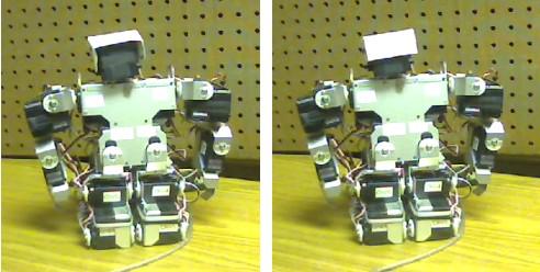
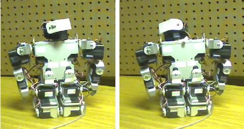
118 Table 6.1 KHR-1 Gestures Gesture name Gesture strokes khr1_home khr1_box_gesture khr1_point_up_ri ght_gesture khr1_starburst_g esture khr1_head_updown _gesture khr1_head_leftri ght_gesture 110
119 The first segment shows the KHR-1 robot execute the Scenario without modification from any music data. The remaining three segments show the KHR-1 robot executing the same Scenario with the addition of three music data (in order): Beethoven's Symphony No. 5, Lullaby of Birdland, and the Pink Panther Theme song. The same set of questions as above is used for the survey of this second experiment. The survey questionnaires can be seen in Appendix A and B for the Dance and Scenario performances, respectively. Survey participants' comments are compiled in Appendix C verbatim, with minor spelling corrections. The next section will discuss the result of the two surveys. The results of each question item are discussed first, then followed by a summary and afterthoughts on the results The Results Survey 1: Motion Generated from Music Data Timing As mentioned above, the first question on the survey is about how the movements of the robot match the timing of the music, and is rated on a 5-point Lichter scale (1: Very Bad, 2: Bad, 3: OK, 4: Good, 5: Very Good). To analyze the results, the average score of each robot performance is calculated. The total score from all participants are calculated then divided by the number of participants that submitted scores for the particular robot23. The results on timing for all five performances are shown in Figure Some participants did not enter any score for one or more of the robot performances. Robot A: N=28, Robot B: N=29, Robot C: N=28, Robot D: N=29, Robot E: N=28 111
120 Dance Survey Q1: How well do the robot's movements match the timing of the music? Robot E 1.75 Robot D 2.76 Robot C 2.89 Robot B 3.34 Robot A Average Score (total score/queries) Figure 6.1: Survey 1 Timing results. On average, participants rated Performance A and Performance B above OK (at 3.18 and 3.34 average, respectively) while Performance C and D are close to OK, (at 2.89 and 2.76 average, respectively) and Performance E was rated close to Bad. (at 1.75) This result indicates that the timing scheme on the program works fairly well. Note that during the videotaping, the music and the motion execution was done using two separate processes which made it difficult to make the music to start on-time with the music. This issue might contribute to the robot to appear not moving on-time with the music; lagging in particular. However, the results indicate that most of the performances were perceived by the audience to be following the timing of the music fairly well, although do not always perfectly match. Approximately ten participants commented that Performance B has good timing, sync with the music, or other similar statements (see Section ). 112
121 The performance of Performance E, which was created by hand, scored lower than the other four performances which was generated automatically. This indicates that, either: a) The author of performance of Performance E had difficulty (or incompetent) in creating the timing for the movements, b) The timing of the execution of a motion sequence of such length cannot be specified completely in the ASC16 command format some additional timing control from the sending program is required, or c) The proposed system is able to perform better in controlling timing than the average human author. At this point, it can be said that the system performed well in terms of controlling the timing of the movements, but no conclusions can be drawn yet on whether or not the system performs better than human authors on average. In future studies, given enough time, a different and/or better author may able to produce similar or better timing on the performance. One thing for sure is that the human author will need more time to create good timing for the performance than the proposed system Expressing the Music The scores for the robot's musical expression were calculated in the same way as the Timing performance above (Section ). The results are shown in Figure
122 Dance Survey Q2: How well do the robot's movements express the music? Robot E 1.96 Robot D 2.41 Robot C 2.61 Robot B 3.41 Robot A Average Score (total score/queries) Figure 6.2: Survey 1 Expressiveness results. The result indicates that among all the performances, Performance B has the best expressiveness score (on average) at 3.41, which is above OK. Performance A is rated second to Performance B. Performance C and D are rated slightly better than Bad, and Performance E got the lowest score at (almost) Bad. Overall, the results are similar to the results on Timing above. This result indicates that the model used in the system to describe the relationship between the contents of note events: timing, pitch, note-on velocities, note duration of the music with movement properties: timing, direction, speed, and range of the movements (see Section 5.3.4) is appropriate. In other words, this result seems to confirm that expressive motions can indeed be derived from music information. Interestingly, some of the movements generated on Performance A, B, C, and D appeared like beat gestures, i.e. repeating movements, such as: left-right, up-down. The beat 114
123 gestures are especially apparent in Performance D which the robot generates the motion data from the Pink Panther Theme song. In the 30-seconds clip that was shown of Performance D, the robot moved only to left and right from the base joint, and tilting left and right on the end joint ('face'). This movement is repeated throughout the clip. The track used from this particular song has highly repeated melody patterns. The Pink Panther Theme song itself presents a sense of sneakiness, and mysteriousness yet playful, which appropriately expresses the movie the song represents24. Therefore it seems to make sense that the generated motion data exhibit repetitions. Also, Performance D has very few movements because there are many pauses with fairly long durations (roughly seconds) in the track. In contrast, Performance B which 'danced' to the Mozart Sonata No. 16 exhibits very many movements because of the continuous melody in the song with very little or few pauses in between. The Mozart Sonata No. 16 is a very upbeat song, and present a happy, cheerful, or 'bright' feeling. In the beginning of the song, the pose of Performance B gradually extends upwards (Figure 6.3). Performance B performed the 'dance' in a very extended upwards pose in most of the 30-seconds segment shown. The range of motion of the movements of Performance B tends to be very small, and very beat-gesture-like (i.e. left-right, up-down, front-back). The small range of motion is caused by the short time distance between one note event and the next in the song. Consequently, before each timed event (i.e. position data) can reach its end position, the next timed event is already sent to the ASC16 and is executed. However, there is enough time in between the timed events for each timed event to be executed. 24 The Pink Panther movie is a comedy about a clumsy police inspector investigating a famous cat-burglar who always managed to escape the police. 115

124 Figure 6.3: The Lynxmotion robot pose dancing to Mozart Sonata No. 16. The combination of extended upwards pose and the frequent, albeit small movements of Performance B to the nuance of the song is in conjunction with the Effort concept in LMA. The Effort concept of LMA describes the relationships between the dynamics in a person's movement and his/her intentions. LMA states that movements with light Weight Effort quality tends to be upwards, away from the ground as if defying gravity [12] Overall Performance Again, the scores for the robot's overall performance were calculated in the same way as the Timing (Section ) and Expression (Section ) performances. The overall performance result is shown in Figure
Shimon: An Interactive Improvisational Robotic Marimba Player
 Shimon: An Interactive Improvisational Robotic Marimba Player Guy Hoffman Georgia Institute of Technology Center for Music Technology 840 McMillan St. Atlanta, GA 30332 USA ghoffman@gmail.com Gil Weinberg
Expressive information
 Expressive information 1. Emotions 2. Laban Effort space (gestures) 3. Kinestetic space (music performance) 4. Performance worm 5. Action based metaphor 1 Motivations " In human communication, two channels
Development of extemporaneous performance by synthetic actors in the rehearsal process
 Development of extemporaneous performance by synthetic actors in the rehearsal process Tony Meyer and Chris Messom IIMS, Massey University, Auckland, New Zealand T.A.Meyer@massey.ac.nz Abstract. Autonomous
Sound visualization through a swarm of fireflies
 Sound visualization through a swarm of fireflies Ana Rodrigues, Penousal Machado, Pedro Martins, and Amílcar Cardoso CISUC, Deparment of Informatics Engineering, University of Coimbra, Coimbra, Portugal
Application of a Musical-based Interaction System to the Waseda Flutist Robot WF-4RIV: Development Results and Performance Experiments
 The Fourth IEEE RAS/EMBS International Conference on Biomedical Robotics and Biomechatronics Roma, Italy. June 24-27, 2012 Application of a Musical-based Interaction System to the Waseda Flutist Robot
Laboratory Assignment 3. Digital Music Synthesis: Beethoven s Fifth Symphony Using MATLAB
 Laboratory Assignment 3 Digital Music Synthesis: Beethoven s Fifth Symphony Using MATLAB PURPOSE In this laboratory assignment, you will use MATLAB to synthesize the audio tones that make up a well-known
AN ARTISTIC TECHNIQUE FOR AUDIO-TO-VIDEO TRANSLATION ON A MUSIC PERCEPTION STUDY
 AN ARTISTIC TECHNIQUE FOR AUDIO-TO-VIDEO TRANSLATION ON A MUSIC PERCEPTION STUDY Eugene Mikyung Kim Department of Music Technology, Korea National University of Arts eugene@u.northwestern.edu ABSTRACT
Computer Coordination With Popular Music: A New Research Agenda 1
 Computer Coordination With Popular Music: A New Research Agenda 1 Roger B. Dannenberg roger.dannenberg@cs.cmu.edu http://www.cs.cmu.edu/~rbd School of Computer Science Carnegie Mellon University Pittsburgh,
Empirical Evaluation of Animated Agents In a Multi-Modal E-Retail Application
 From: AAAI Technical Report FS-00-04. Compilation copyright 2000, AAAI (www.aaai.org). All rights reserved. Empirical Evaluation of Animated Agents In a Multi-Modal E-Retail Application Helen McBreen,
EMERGENT SOUNDSCAPE COMPOSITION: REFLECTIONS ON VIRTUALITY
 EMERGENT SOUNDSCAPE COMPOSITION: REFLECTIONS ON VIRTUALITY by Mark Christopher Brady Bachelor of Science (Honours), University of Cape Town, 1994 THESIS SUBMITTED IN PARTIAL FULFILLMENT OF THE REQUIREMENTS
Authors: Kasper Marklund, Anders Friberg, Sofia Dahl, KTH, Carlo Drioli, GEM, Erik Lindström, UUP Last update: November 28, 2002
 Groove Machine Authors: Kasper Marklund, Anders Friberg, Sofia Dahl, KTH, Carlo Drioli, GEM, Erik Lindström, UUP Last update: November 28, 2002 1. General information Site: Kulturhuset-The Cultural Centre
DAT335 Music Perception and Cognition Cogswell Polytechnical College Spring Week 6 Class Notes
 DAT335 Music Perception and Cognition Cogswell Polytechnical College Spring 2009 Week 6 Class Notes Pitch Perception Introduction Pitch may be described as that attribute of auditory sensation in terms
MAKING INTERACTIVE GUIDES MORE ATTRACTIVE
 MAKING INTERACTIVE GUIDES MORE ATTRACTIVE Anton Nijholt Department of Computer Science University of Twente, Enschede, the Netherlands anijholt@cs.utwente.nl Abstract We investigate the different roads
MELODIC AND RHYTHMIC CONTRASTS IN EMOTIONAL SPEECH AND MUSIC
 MELODIC AND RHYTHMIC CONTRASTS IN EMOTIONAL SPEECH AND MUSIC Lena Quinto, William Forde Thompson, Felicity Louise Keating Psychology, Macquarie University, Australia lena.quinto@mq.edu.au Abstract Many
Analysis, Synthesis, and Perception of Musical Sounds
 Analysis, Synthesis, and Perception of Musical Sounds The Sound of Music James W. Beauchamp Editor University of Illinois at Urbana, USA 4y Springer Contents Preface Acknowledgments vii xv 1. Analysis
Toward a Computationally-Enhanced Acoustic Grand Piano
 Toward a Computationally-Enhanced Acoustic Grand Piano Andrew McPherson Electrical & Computer Engineering Drexel University 3141 Chestnut St. Philadelphia, PA 19104 USA apm@drexel.edu Youngmoo Kim Electrical
Robert Alexandru Dobre, Cristian Negrescu
 ECAI 2016 - International Conference 8th Edition Electronics, Computers and Artificial Intelligence 30 June -02 July, 2016, Ploiesti, ROMÂNIA Automatic Music Transcription Software Based on Constant Q
Embodied music cognition and mediation technology
 Embodied music cognition and mediation technology Briefly, what it is all about: Embodied music cognition = Experiencing music in relation to our bodies, specifically in relation to body movements, both
TOWARD AN INTELLIGENT EDITOR FOR JAZZ MUSIC
 TOWARD AN INTELLIGENT EDITOR FOR JAZZ MUSIC G.TZANETAKIS, N.HU, AND R.B. DANNENBERG Computer Science Department, Carnegie Mellon University 5000 Forbes Avenue, Pittsburgh, PA 15213, USA E-mail: gtzan@cs.cmu.edu
UNIVERSITY OF DUBLIN TRINITY COLLEGE
 UNIVERSITY OF DUBLIN TRINITY COLLEGE FACULTY OF ENGINEERING & SYSTEMS SCIENCES School of Engineering and SCHOOL OF MUSIC Postgraduate Diploma in Music and Media Technologies Hilary Term 31 st January 2005
SYNTHESIS FROM MUSICAL INSTRUMENT CHARACTER MAPS
 Published by Institute of Electrical Engineers (IEE). 1998 IEE, Paul Masri, Nishan Canagarajah Colloquium on "Audio and Music Technology"; November 1998, London. Digest No. 98/470 SYNTHESIS FROM MUSICAL
Environment Expression: Expressing Emotions through Cameras, Lights and Music
 Environment Expression: Expressing Emotions through Cameras, Lights and Music Celso de Melo, Ana Paiva IST-Technical University of Lisbon and INESC-ID Avenida Prof. Cavaco Silva Taguspark 2780-990 Porto
Universal Event and Motion Editor for Robots Theatre. Aditya Bhutada. A thesis submitted in partial fulfillment of the requirements for the degree of
 Universal Event and Motion Editor for Robots Theatre by Aditya Bhutada A thesis submitted in partial fulfillment of the requirements for the degree of Master of Science in Electrical and Computer Engineering
2. AN INTROSPECTION OF THE MORPHING PROCESS
 1. INTRODUCTION Voice morphing means the transition of one speech signal into another. Like image morphing, speech morphing aims to preserve the shared characteristics of the starting and final signals,
Doctor of Philosophy
 University of Adelaide Elder Conservatorium of Music Faculty of Humanities and Social Sciences Declarative Computer Music Programming: using Prolog to generate rule-based musical counterpoints by Robert
Musical Entrainment Subsumes Bodily Gestures Its Definition Needs a Spatiotemporal Dimension
 Musical Entrainment Subsumes Bodily Gestures Its Definition Needs a Spatiotemporal Dimension MARC LEMAN Ghent University, IPEM Department of Musicology ABSTRACT: In his paper What is entrainment? Definition
Sentiment Extraction in Music
 Sentiment Extraction in Music Haruhiro KATAVOSE, Hasakazu HAl and Sei ji NOKUCH Department of Control Engineering Faculty of Engineering Science Osaka University, Toyonaka, Osaka, 560, JAPAN Abstract This
Music Performance Panel: NICI / MMM Position Statement
 Music Performance Panel: NICI / MMM Position Statement Peter Desain, Henkjan Honing and Renee Timmers Music, Mind, Machine Group NICI, University of Nijmegen mmm@nici.kun.nl, www.nici.kun.nl/mmm In this
Extreme Experience Research Report
 Extreme Experience Research Report Contents Contents 1 Introduction... 1 1.1 Key Findings... 1 2 Research Summary... 2 2.1 Project Purpose and Contents... 2 2.1.2 Theory Principle... 2 2.1.3 Research Architecture...
However, in studies of expressive timing, the aim is to investigate production rather than perception of timing, that is, independently of the listene
 Beat Extraction from Expressive Musical Performances Simon Dixon, Werner Goebl and Emilios Cambouropoulos Austrian Research Institute for Artificial Intelligence, Schottengasse 3, A-1010 Vienna, Austria.
Walt Stanchfield 03 Notes from Walt Stanchfield s Disney Drawing Classes
 Walt Stanchfield 03 Notes from Walt Stanchfield s Disney Drawing Classes Action Analyisis by Walt Stanchfield PDF produced by www.animationmeat.com 1 FOR THE ACTION ANALYSIS CLASS Here is a sheet of figures
GENERAL WRITING FORMAT
 GENERAL WRITING FORMAT The doctoral dissertation should be written in a uniform and coherent manner. Below is the guideline for the standard format of a doctoral research paper: I. General Presentation
ADJUDICATION SHEET CRAFTS
 CRAFTS NAME ZONE: JUNIOR PRIMARY AGE 1. Originality 2. Craftsmanship/Degree of Difficulty 3. Creative use of media 4. Presentation 5. Composition and design 6. Interpretation of theme 7. Detail 8. Requirements
The Tone Height of Multiharmonic Sounds. Introduction
 Music-Perception Winter 1990, Vol. 8, No. 2, 203-214 I990 BY THE REGENTS OF THE UNIVERSITY OF CALIFORNIA The Tone Height of Multiharmonic Sounds ROY D. PATTERSON MRC Applied Psychology Unit, Cambridge,
About Giovanni De Poli. What is Model. Introduction. di Poli: Methodologies for Expressive Modeling of/for Music Performance
 Methodologies for Expressiveness Modeling of and for Music Performance by Giovanni De Poli Center of Computational Sonology, Department of Information Engineering, University of Padova, Padova, Italy About
PEP-I1 RF Feedback System Simulation
 SLAC-PUB-10378 PEP-I1 RF Feedback System Simulation Richard Tighe SLAC A model containing the fundamental impedance of the PEP- = I1 cavity along with the longitudinal beam dynamics and feedback system
Speech Recognition and Signal Processing for Broadcast News Transcription
 2.2.1 Speech Recognition and Signal Processing for Broadcast News Transcription Continued research and development of a broadcast news speech transcription system has been promoted. Universities and researchers
Music Representations
 Lecture Music Processing Music Representations Meinard Müller International Audio Laboratories Erlangen meinard.mueller@audiolabs-erlangen.de Book: Fundamentals of Music Processing Meinard Müller Fundamentals
Follow the Beat? Understanding Conducting Gestures from Video
 Follow the Beat? Understanding Conducting Gestures from Video Andrea Salgian 1, Micheal Pfirrmann 1, and Teresa M. Nakra 2 1 Department of Computer Science 2 Department of Music The College of New Jersey
Computational Parsing of Melody (CPM): Interface Enhancing the Creative Process during the Production of Music
: Interface Enhancing the Creative Process during the Production of Music") Computational Parsing of Melody (CPM): Interface Enhancing the Creative Process during the Production of Music Andrew Blake and Cathy Grundy University of Westminster Cavendish School of Computer Science
Computational Parsing of Melody (CPM): Interface Enhancing the Creative Process during the Production of Music Andrew Blake and Cathy Grundy University of Westminster Cavendish School of Computer Science
Seminar CHIST-ERA Istanbul : 4 March 2014 Kick-off meeting : 27 January 2014 (call IUI 2012)
") project JOKER JOKe and Empathy of a Robot/ECA: Towards social and affective relations with a robot Seminar CHIST-ERA Istanbul : 4 March 2014 Kick-off meeting : 27 January 2014 (call IUI 2012) http://www.chistera.eu/projects/joker
project JOKER JOKe and Empathy of a Robot/ECA: Towards social and affective relations with a robot Seminar CHIST-ERA Istanbul : 4 March 2014 Kick-off meeting : 27 January 2014 (call IUI 2012) http://www.chistera.eu/projects/joker
Interacting with a Virtual Conductor
 Interacting with a Virtual Conductor Pieter Bos, Dennis Reidsma, Zsófia Ruttkay, Anton Nijholt HMI, Dept. of CS, University of Twente, PO Box 217, 7500AE Enschede, The Netherlands anijholt@ewi.utwente.nl
MONITORING AND ANALYSIS OF VIBRATION SIGNAL BASED ON VIRTUAL INSTRUMENTATION
 MONITORING AND ANALYSIS OF VIBRATION SIGNAL BASED ON VIRTUAL INSTRUMENTATION Abstract Sunita Mohanta 1, Umesh Chandra Pati 2 Post Graduate Scholar, NIT Rourkela, India 1 Associate Professor, NIT Rourkela,
Multimodal databases at KTH
 Multimodal databases at David House, Jens Edlund & Jonas Beskow Clarin Workshop The QSMT database (2002): Facial & Articulatory motion Clarin Workshop Purpose Obtain coherent data for modelling and animation
Laugh when you re winning
 Laugh when you re winning Harry Griffin for the ILHAIRE Consortium 26 July, 2013 ILHAIRE Laughter databases Laugh when you re winning project Concept & Design Architecture Multimodal analysis Overview
Processing. Electrical Engineering, Department. IIT Kanpur. NPTEL Online - IIT Kanpur
 NPTEL Online - IIT Kanpur Course Name Department Instructor : Digital Video Signal Processing Electrical Engineering, : IIT Kanpur : Prof. Sumana Gupta file:///d /...e%20(ganesh%20rana)/my%20course_ganesh%20rana/prof.%20sumana%20gupta/final%20dvsp/lecture1/main.htm[12/31/2015
Thursday, April 28, 16
 Drama Unit Learning Targets I can analyze the development of a theme over the course of a text. I can analyze how a drama s form or structure contributes to its meaning. I can compare and contrast a written
Usability of Computer Music Interfaces for Simulation of Alternate Musical Systems
 Usability of Computer Music Interfaces for Simulation of Alternate Musical Systems Dionysios Politis, Ioannis Stamelos {Multimedia Lab, Programming Languages and Software Engineering Lab}, Department of
QUALITY OF COMPUTER MUSIC USING MIDI LANGUAGE FOR DIGITAL MUSIC ARRANGEMENT
 QUALITY OF COMPUTER MUSIC USING MIDI LANGUAGE FOR DIGITAL MUSIC ARRANGEMENT Pandan Pareanom Purwacandra 1, Ferry Wahyu Wibowo 2 Informatics Engineering, STMIK AMIKOM Yogyakarta 1 pandanharmony@gmail.com,
Brain.fm Theory & Process
 Brain.fm Theory & Process At Brain.fm we develop and deliver functional music, directly optimized for its effects on our behavior. Our goal is to help the listener achieve desired mental states such as
6.UAP Project. FunPlayer: A Real-Time Speed-Adjusting Music Accompaniment System. Daryl Neubieser. May 12, 2016
 6.UAP Project FunPlayer: A Real-Time Speed-Adjusting Music Accompaniment System Daryl Neubieser May 12, 2016 Abstract: This paper describes my implementation of a variable-speed accompaniment system that
VivoSense. User Manual Galvanic Skin Response (GSR) Analysis Module. VivoSense, Inc. Newport Beach, CA, USA Tel. (858) , Fax.
 Analysis Module. VivoSense, Inc. Newport Beach, CA, USA Tel. (858) , Fax.") VivoSense User Manual Galvanic Skin Response (GSR) Analysis VivoSense Version 3.1 VivoSense, Inc. Newport Beach, CA, USA Tel. (858) 876-8486, Fax. (248) 692-0980 Email: info@vivosense.com; Web: www.vivosense.com
VivoSense User Manual Galvanic Skin Response (GSR) Analysis VivoSense Version 3.1 VivoSense, Inc. Newport Beach, CA, USA Tel. (858) 876-8486, Fax. (248) 692-0980 Email: info@vivosense.com; Web: www.vivosense.com
A System for Generating Real-Time Visual Meaning for Live Indian Drumming
 A System for Generating Real-Time Visual Meaning for Live Indian Drumming Philip Davidson 1 Ajay Kapur 12 Perry Cook 1 philipd@princeton.edu akapur@princeton.edu prc@princeton.edu Department of Computer
Understanding PQR, DMOS, and PSNR Measurements
 Understanding PQR, DMOS, and PSNR Measurements Introduction Compression systems and other video processing devices impact picture quality in various ways. Consumers quality expectations continue to rise
CM3106 Solutions. Do not turn this page over until instructed to do so by the Senior Invigilator.
 CARDIFF UNIVERSITY EXAMINATION PAPER Academic Year: 2013/2014 Examination Period: Examination Paper Number: Examination Paper Title: Duration: Autumn CM3106 Solutions Multimedia 2 hours Do not turn this
A prototype system for rule-based expressive modifications of audio recordings
 International Symposium on Performance Science ISBN 0-00-000000-0 / 000-0-00-000000-0 The Author 2007, Published by the AEC All rights reserved A prototype system for rule-based expressive modifications
Introduction to Musical theatre: Musical Theatre Foundations I Session Design by: Kimberly Lamping and Molly Cameron Revised by: Kimberly Lamping
 Introduction to Musical theatre: Musical Theatre Foundations I Session Design by: Kimberly Lamping and Molly Cameron Revised by: Kimberly Lamping LEARNING OBJECTIVES Content Standards Utah Music Standard
1 Overview. 1.1 Nominal Project Requirements
 15-323/15-623 Spring 2018 Project 5. Real-Time Performance Interim Report Due: April 12 Preview Due: April 26-27 Concert: April 29 (afternoon) Report Due: May 2 1 Overview In this group or solo project,
Anthropomorphism. the rationalization of animal or system behavior through superposing aspects of the human observer.
 Wizard of Oz Anthropomorphism the rationalization of animal or system behavior through superposing aspects of the human observer. Having a naturalistic embodiment is often cited as necessary for meaningful
Lecture 1: What we hear when we hear music
 Lecture 1: What we hear when we hear music What is music? What is sound? What makes us find some sounds pleasant (like a guitar chord) and others unpleasant (a chainsaw)? Sound is variation in air pressure.
Essential Question: Where do choreographers get ideas for dances?
 Dance 2: Creating Process Component: Explore Anchor Standard 1: Generate and conceptualize artistic ideas and work. Enduring Understanding: Choreographers use a variety of sources as inspiration and transform
GUIDELINES FOR PREPARATION OF ARTICLE STYLE THESIS AND DISSERTATION
 GUIDELINES FOR PREPARATION OF ARTICLE STYLE THESIS AND DISSERTATION SCHOOL OF GRADUATE AND PROFESSIONAL STUDIES SUITE B-400 AVON WILLIAMS CAMPUS WWW.TNSTATE.EDU/GRADUATE September 2018 P a g e 2 Table
Pitch correction on the human voice
 University of Arkansas, Fayetteville ScholarWorks@UARK Computer Science and Computer Engineering Undergraduate Honors Theses Computer Science and Computer Engineering 5-2008 Pitch correction on the human
ONLINE ACTIVITIES FOR MUSIC INFORMATION AND ACOUSTICS EDUCATION AND PSYCHOACOUSTIC DATA COLLECTION
 ONLINE ACTIVITIES FOR MUSIC INFORMATION AND ACOUSTICS EDUCATION AND PSYCHOACOUSTIC DATA COLLECTION Travis M. Doll Ray V. Migneco Youngmoo E. Kim Drexel University, Electrical & Computer Engineering {tmd47,rm443,ykim}@drexel.edu
CHILDREN S CONCEPTUALISATION OF MUSIC
 R. Kopiez, A. C. Lehmann, I. Wolther & C. Wolf (Eds.) Proceedings of the 5th Triennial ESCOM Conference CHILDREN S CONCEPTUALISATION OF MUSIC Tânia Lisboa Centre for the Study of Music Performance, Royal
Pitch Perception. Roger Shepard
 Pitch Perception Roger Shepard Pitch Perception Ecological signals are complex not simple sine tones and not always periodic. Just noticeable difference (Fechner) JND, is the minimal physical change detectable
PS User Guide Series Seismic-Data Display
 PS User Guide Series 2015 Seismic-Data Display Prepared By Choon B. Park, Ph.D. January 2015 Table of Contents Page 1. File 2 2. Data 2 2.1 Resample 3 3. Edit 4 3.1 Export Data 4 3.2 Cut/Append Records
OBJECTIVE EVALUATION OF A MELODY EXTRACTOR FOR NORTH INDIAN CLASSICAL VOCAL PERFORMANCES
 OBJECTIVE EVALUATION OF A MELODY EXTRACTOR FOR NORTH INDIAN CLASSICAL VOCAL PERFORMANCES Vishweshwara Rao and Preeti Rao Digital Audio Processing Lab, Electrical Engineering Department, IIT-Bombay, Powai,
Musical Creativity. Jukka Toivanen Introduction to Computational Creativity Dept. of Computer Science University of Helsinki
 Musical Creativity Jukka Toivanen Introduction to Computational Creativity Dept. of Computer Science University of Helsinki Basic Terminology Melody = linear succession of musical tones that the listener
D-Lab & D-Lab Control Plan. Measure. Analyse. User Manual
 D-Lab & D-Lab Control Plan. Measure. Analyse User Manual Valid for D-Lab Versions 2.0 and 2.1 September 2011 Contents Contents 1 Initial Steps... 6 1.1 Scope of Supply... 6 1.1.1 Optional Upgrades... 6
National Coalition for Core Arts Standards. Music Model Cornerstone Assessment: General Music Grades 3-5
 National Coalition for Core Arts Standards Music Model Cornerstone Assessment: General Music Grades 3-5 Discipline: Music Artistic Processes: Perform Title: Performing: Realizing artistic ideas and work
LAUGHTER IN SOCIAL ROBOTICS WITH HUMANOIDS AND ANDROIDS
 LAUGHTER IN SOCIAL ROBOTICS WITH HUMANOIDS AND ANDROIDS Christian Becker-Asano Intelligent Robotics and Communication Labs, ATR, Kyoto, Japan OVERVIEW About research at ATR s IRC labs in Kyoto, Japan Motivation
Expressive performance in music: Mapping acoustic cues onto facial expressions
 International Symposium on Performance Science ISBN 978-94-90306-02-1 The Author 2011, Published by the AEC All rights reserved Expressive performance in music: Mapping acoustic cues onto facial expressions
An Indian Journal FULL PAPER ABSTRACT KEYWORDS. Trade Science Inc.
 [Type text] [Type text] [Type text] ISSN : 0974-7435 Volume 10 Issue 15 BioTechnology 2014 An Indian Journal FULL PAPER BTAIJ, 10(15), 2014 [8863-8868] Study on cultivating the rhythm sensation of the
Automatic Construction of Synthetic Musical Instruments and Performers
 Ph.D. Thesis Proposal Automatic Construction of Synthetic Musical Instruments and Performers Ning Hu Carnegie Mellon University Thesis Committee Roger B. Dannenberg, Chair Michael S. Lewicki Richard M.
AUTOMATIC ACCOMPANIMENT OF VOCAL MELODIES IN THE CONTEXT OF POPULAR MUSIC
 AUTOMATIC ACCOMPANIMENT OF VOCAL MELODIES IN THE CONTEXT OF POPULAR MUSIC A Thesis Presented to The Academic Faculty by Xiang Cao In Partial Fulfillment of the Requirements for the Degree Master of Science
Getting Started with the LabVIEW Sound and Vibration Toolkit
 1 Getting Started with the LabVIEW Sound and Vibration Toolkit This tutorial is designed to introduce you to some of the sound and vibration analysis capabilities in the industry-leading software tool
The Musicat Ptaupen: An Immersive Digitat Musicat Instrument
 The Musicat Ptaupen: An Immersive Digitat Musicat Instrument Gil Weinberg MIT Media Lab, Cambridge, MA, USA Abstract= A digital musical instrument, the "Musical Playpen", was developed in an effort to
12/7/2018 E-1 1
 E-1 1 The overall plan in session 2 is to target Thoughts and Emotions. By providing basic information on hearing loss and tinnitus, the unknowns, misconceptions, and fears will often be alleviated. Later,
Take a Break, Bach! Let Machine Learning Harmonize That Chorale For You. Chris Lewis Stanford University
 Take a Break, Bach! Let Machine Learning Harmonize That Chorale For You Chris Lewis Stanford University cmslewis@stanford.edu Abstract In this project, I explore the effectiveness of the Naive Bayes Classifier
Zooming into saxophone performance: Tongue and finger coordination
 International Symposium on Performance Science ISBN 978-2-9601378-0-4 The Author 2013, Published by the AEC All rights reserved Zooming into saxophone performance: Tongue and finger coordination Alex Hofmann
Sudoku Music: Systems and Readymades
 Sudoku Music: Systems and Readymades Paper Given for the First International Conference on Minimalism, University of Wales, Bangor, 31 August 2 September 2007 Christopher Hobbs, Coventry University Most
Extracting vital signs with smartphone. camera
 Extracting vital signs with smartphone camera Miguel García Plo January 2016 PROJECT Department of Electronics and Telecommunications Norwegian University of Science and Technology Supervisor 1: Ilangko
Speaking in Minor and Major Keys
 Chapter 5 Speaking in Minor and Major Keys 5.1. Introduction 28 The prosodic phenomena discussed in the foregoing chapters were all instances of linguistic prosody. Prosody, however, also involves extra-linguistic
Building a Better Bach with Markov Chains
 Building a Better Bach with Markov Chains CS701 Implementation Project, Timothy Crocker December 18, 2015 1 Abstract For my implementation project, I explored the field of algorithmic music composition
APPLICATIONS OF A SEMI-AUTOMATIC MELODY EXTRACTION INTERFACE FOR INDIAN MUSIC
 APPLICATIONS OF A SEMI-AUTOMATIC MELODY EXTRACTION INTERFACE FOR INDIAN MUSIC Vishweshwara Rao, Sachin Pant, Madhumita Bhaskar and Preeti Rao Department of Electrical Engineering, IIT Bombay {vishu, sachinp,
Topic 10. Multi-pitch Analysis
 Topic 10 Multi-pitch Analysis What is pitch? Common elements of music are pitch, rhythm, dynamics, and the sonic qualities of timbre and texture. An auditory perceptual attribute in terms of which sounds
Chapter. Arts Education
 Chapter 8 205 206 Chapter 8 These subjects enable students to express their own reality and vision of the world and they help them to communicate their inner images through the creation and interpretation
A Bayesian Network for Real-Time Musical Accompaniment
 A Bayesian Network for Real-Time Musical Accompaniment Christopher Raphael Department of Mathematics and Statistics, University of Massachusetts at Amherst, Amherst, MA 01003-4515, raphael~math.umass.edu
OCTAVE C 3 D 3 E 3 F 3 G 3 A 3 B 3 C 4 D 4 E 4 F 4 G 4 A 4 B 4 C 5 D 5 E 5 F 5 G 5 A 5 B 5. Middle-C A-440
 DSP First Laboratory Exercise # Synthesis of Sinusoidal Signals This lab includes a project on music synthesis with sinusoids. One of several candidate songs can be selected when doing the synthesis program.
Expressive arts Experiences and outcomes
 Expressive arts Experiences and outcomes Experiences in the expressive arts involve creating and presenting and are practical and experiential. Evaluating and appreciating are used to enhance enjoyment
Wednesday, November 7, 12
 Drama Unit Learning Targets I can analyze the development of a theme over the course of a text. I can analyze how particular elements of a drama interact. I can analyze how a drama s form or structure
The Effects of Humor Therapy on Older Adults. Mariah Stump
 The Effects of Humor Therapy on Older Adults Mariah Stump Introduction Smiling, laughing, and humor is something that individuals come across everyday. People watch humorous videos, listen to comedians,
SRV02-Series. Rotary Pendulum. User Manual
 SRV02-Series Rotary Pendulum User Manual Table of Contents 1. Description...3 2. Purchase Options...3 2.1 Modular Options...4 3. System Nomenclature and Components...5 4. System Configuration and Assembly...6
How to Combat Eye Fatigue Right Now
 How to Combat Eye Fatigue Right Now Change your work environment by changing how you use your monitor A brief guide that introduces survey results about PC usage and eye fatigue and what to do about it.
PSYCHOACOUSTICS & THE GRAMMAR OF AUDIO (By Steve Donofrio NATF)
") PSYCHOACOUSTICS & THE GRAMMAR OF AUDIO (By Steve Donofrio NATF) "The reason I got into playing and producing music was its power to travel great distances and have an emotional impact on people" Quincey
PSYCHOACOUSTICS & THE GRAMMAR OF AUDIO (By Steve Donofrio NATF) "The reason I got into playing and producing music was its power to travel great distances and have an emotional impact on people" Quincey
Breathe Life Into Your Conducting Dr. Erica Neidlinger DePaul University. Breathing as a Player vs. Breathing as a Conductor
 Breathe Life Into Your Conducting Dr. Erica Neidlinger DePaul University Breathing as a Player vs. Breathing as a Conductor 1. Breathing as a player is different than breathing as a conductor. Wind players
Smooth Rhythms as Probes of Entrainment. Music Perception 10 (1993): ABSTRACT
: ABSTRACT") Smooth Rhythms as Probes of Entrainment Music Perception 10 (1993): 503-508 ABSTRACT If one hypothesizes rhythmic perception as a process employing oscillatory circuits in the brain that entrain to low-frequency
Smooth Rhythms as Probes of Entrainment Music Perception 10 (1993): 503-508 ABSTRACT If one hypothesizes rhythmic perception as a process employing oscillatory circuits in the brain that entrain to low-frequency
Connecticut Common Arts Assessment Initiative
 Music Composition and Self-Evaluation Assessment Task Grade 5 Revised Version 5/19/10 Connecticut Common Arts Assessment Initiative Connecticut State Department of Education Contacts Scott C. Shuler, Ph.D.
vision and/or playwright's intent. relevant to the school climate and explore using body movements, sounds, and imagination.
 Critical Thinking and Reflection TH.K.C.1.1 TH.1.C.1.1 TH.2.C.1.1 TH.3.C.1.1 TH.4.C.1.1 TH.5.C.1.1 TH.68.C.1.1 TH.912.C.1.1 TH.912.C.1.7 Create a story about an Create a story and act it out, Describe