INTRODUCTION IMPORTANT SAFTEY INSTRUCTIONS
|
|
|
- Dylan Golden
- 5 years ago
- Views:
Transcription
1


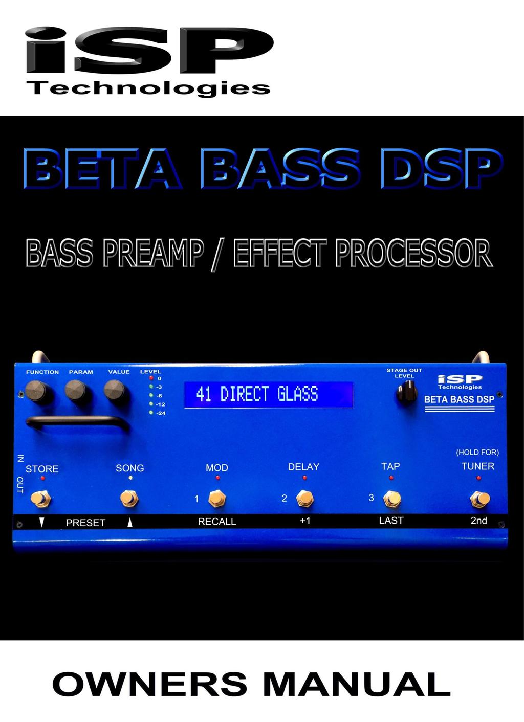
2 INTRODUCTION Congratulations on your purchase of the BETA BASS DSP. The BETA BASS DSP was designed to provide the ultimate sonic performance possible in a BASS GUITAR DSP based processor; all controlled on the floor, with simplicity of use and programmability. The BETA BASS DSP is based on state of the art Digital and Analog circuit design and technology and features ISP Technologies proprietary algorithms for all BETA BASS DSP functions. The BETA BASS DSP also features the patented Decimator noise reduction system for the highest level of noise reduction and transparency available. Also included on board is a SONG mode allowing the guitarist to arrange presets into 124 songs with 3 preset patches per SONG. Please read this manual carefully for a through explanation of the BETA BASS DSP and its functions. IMPORTANT SAFTEY INSTRUCTIONS Please read the following very carefully before operating this unit Read ALL instructions carefully before using this unit. Keep these instructions for future reference. Heed all warnings and follow all instructions. Do not use this unit near water, in the rain, or where there is moisture. If this warning is ignored a serious electrical shock or death may occur. Do not attempt to service this unit. No user serviceable parts inside. Refer servicing to qualified, ISP approved personnel. Servicing is required when the unit is damaged in any way, such as power adaptor is damaged, liquid has been spilled into the unit, the unit has been exposed to rain or moisture, does not operate normally, or has been dropped. Care should be taken to avoid spilling any foreign objects or liquid into this unit. Avoid exposure of this equipment to dripping or splashing and ensure that no objects filled with liquid, such as vases, are placed on the equipment. Only use accessories or attachments that are specified by the manufacturer. Failure to follow these instructions may void the warranty. NO USER SERVICABLE PARTS INSIDE. REFER SERVICING TO QUALIFIED ISP TECHNOLOGIES SERVICE PERSONNEL. The lightning bolt triangle is used to alert the user to the risk of electric shock. The exclamation point triangle is used to alert the user to important operating or maintenance instructions. POWER REQUIREMENTS This unit requires the connection of the external AC Power Adaptor to a 120 volt AC outlet. Do not attempt to connect this unit to any power source other than the one supplied with the BETA BASS DSP. The BETA BASS DSP will typically draw on the order of 1.5 amps of current from the AC power adaptor when in use.

3 FIGURE 1 BETA DSP v1 Instruction Manual Quick Start Refer to Figure 1 for the hardware drawing which shows the locations of the switches, knobs, and jacks when reading the following, or even better, just look at your unit. 1. Connect the bass to the IN jack, connect the STAGE OUT jack(s) to a power amp such as the isp Stealth which is connected to a speaker cabinet, OR connect the DIRECT OUT jacks to the input of a mixer, OR connect the PHONES jack to headphones or earbuds (or connect all three). If you have a mono system, you can set the output(s) to mono in the global parameters. The STAGE OUT jacks can be connected to a conventional bass amplifier, but this will not yield optimum results, since most bass amps will further shape the sound. You can connect an audio source such as your phone to the AUX IN jack, then play along with tracks while listening via the PHONES OUT or DIRECT OUTs.
4 2. Connect the supplied 9V AC power adaptor to wall power, then to the POWER input on the BETA DSP. The unit will power up and recall Preset 1. Pressing the RECALL 1 switch will display the Preset 1 title. 3. With the Preset title displayed, adjust the INPUT LEVEL control on the back panel so that the LEVEL 0 led (red) just flashes when you play hard, then back off the INPUT LEVEL control slightly so that the 0 led does not light. Short, infrequent flashes of the red 0 led are generally not audible, so don t worry about them. Adjust the STAGE OUT LEVEL or PHONES LEVEL controls to taste. The DIRECT OUT levels can be controlled by the global DIRECT TRIM parameter which affects all presets, and by the OUTPUT LEVEL parameter within each preset, which affects all outputs, but is the level specific to each preset. Note that the LEVEL leds only display the raw input level when the preset or song titles are displayed (FUNCTION turned fully counterclockwise). If any other parameters are displayed, the LEVEL leds will display the maximum of the 4 output DAC (Digital to Analog Converter) levels. 4. Play! 5. Presets can be selected by pressing the PRESET down or up switches, then the RECALL switch. Holding the PRESET down or up switches will result in progressively faster scrolling through the preset titles. The +1 switch will immediately increment one preset, and the LAST switch will immediately recall the last previously recalled preset If the preset title is displayed (if FUNCTION is set fully counterclockwise), the VALUE knob can be turned to scroll through the preset titles. Pressing the RECALL switch will then recall the selected preset. 6. Pressing the 2nd switch allows access to the STORE, SONG Mode, mappable MOD and DELAY on/off switches, as well the TAP switch to set the modulation rates and DELAY time. The precedence for the TAP function is as follows: TAP will be mapped to either the delay time or the modulation rate of the effect that is mapped to the MOD switch by the MOD SWITCH: function. If only the MOD effect is on, TAP will be mapped to that effect. If only the Delay is on, TAP will be mapped to Delay Time. If both are on, right after the 2nd switch is pressed, TAP will map to the delay. However, if the MOD switch is pressed first to turn on the MOD effect, TAP will be mapped to the MOD effect, even if Delay is ON. For example, say you are in a Preset that has both PHASER and DELAY turned on, and MOD SWITCH: PHASER is set. If you want to use TAP to set the Phaser Rate, press 2nd, then press MOD twice to turn PHASER off, then back on. Now TAP will be mapped to set the PHASER Rate. Note that even though the MOD switch can only be mapped to one effect at a time, all effects can be used simultaneously in any preset! However the CRS/PSHIFT is a single effect, so only one of those modes may be used at the same time. 7. Pressing and holding the TUNER switch will activate the tuner. Hitting any other switch will then deactivate the tuner. 8. The FUNCTION knob selects the function such as Preamp, EQ, etc. The PARAM knob selects the parameter within the function, and the VALUE knob adjusts the value. 9. Changing a value will light the red STORE led. To store the new value for later recall, press the 2 nd switch, followed by the STORE switch. Note that the BETA DSP ships with the Preset LOCK set to ON, so storing to
5 those presets will display a FAIL message. Storing to presets is always allowed. See the section on the Global Parameters for more information on how to turn off the Locks. 10. To copy a preset to a different location, first recall the preset. Then scroll to the desired new location by using the PRESET down or up switches, or the VALUE knob (if FUNCTION is set fully counterclockwise). Note that the preset titles will flash, meaning the preset is not fully recalled. Then press 2 nd, STORE to store the last recalled preset into the new location. The original contents of this location will be overwritten, so be carefull. Since the unit ships with 100 unique presets written in locations 1 to 100, then repeated again in locations 101 to 200, we recommend that you leave one of the two banks locked to prevent inadvertantly writing over the original presets, at least until you really need the storage space for your own presets. 11. Read the rest of the manual, it contains much valuable information to get the most from your BETA DSP
6 DETAILED OPERATION: Refer to the figure above for the hardware drawings which show the locations of the switches, knobs, and jacks when reading the following. Refer to Figure 2 for the signal flow diagram which shows the flow of the signal through the unit from the input to the outputs. The following text explains the operation of the unit organized by the software functions and parameters, but it also incorporates explainations of the hardware functions where they are interrelated to the software. Also, many important operational details are contained in the Quick Start section, so reading and understanding that section is essential. PRESET MODE: This is the default mode when the unit is first turned on. It allows direct recall of presets by name, adjustment and programming of presets, mapping of switches and the expression pedal, MIDI Dump and Load, and setting of Global parameters. The other mode of the unit is SONG MODE, which will be described later. Functions and Parameters: Note that the titles of the functions do not always appear on the display, but most of them are contained within the first parameter of that function. The following list of functions are accessed in order by turning the FUNCTION knob clockwise. The parameters are then accessed by turning the PARAM knob. The values displayed are changed by turning the VALUE knob. A) Mixer Function 1. OUTPUT LEVEL (OFF to +10 db): Controls the output level feeding all outputs from the unit. This is to allow the presets to be set to nominally equal levels given different gains, compression, EQ, and effects. It also allows adjustment to prevent clipping of the 4 channel output DAC. When the Function is turned to display this or any parameter other than the titles, the LEVEL leds will display the maximum output level of the 4 DAC channels. The OUTPUT LEVEL can then be adjusted to prevent clipping of the DAC by keeping the red 0 db led from lighting. 2. DIRECT PAN (0 to 100): Pans the direct signal (the signal before the stereo effects) from Left (0) to Right (100). The primary use for this is to have the direct sent to one channel and the delay sent to the other.
7 B) PREAMP Function 1. DISTORT MIX (0 to 100): Varies the relative amounts of clean and distorted signal. 0 means full clean signal, 100 means full distortion signal. 2. GAIN (1 to 60 db): Dials up the gain before the clipper stage. Additionally, there is gain available in the Pre EQ (labeled DIST BASS, DIST MID, DIST TREBLE). 3. HIGH PASS (20 to 240 Hz): Varies the corner frequency (-3 db point) of a high pass filter the precedes the clipper. This allows the low frequency component of your signal to stay clean. 4. SAG (0 to 100): Emulates the sag of the supply voltage rails in a tube amp. Higher values result in more sag. This means that as you play harder, the rails sag down resulting in more clipping of the signal. Play softer and the rails move higher, resulting in a cleaner sound. This is most effective with moderate levels of GAIN. 5. OUTPUT LEVEL (OFF to +10 db): This is the same parameter as in the mixer function. It is just repeated here for convenience because as preamp parameters are changed, it is typical that the output level will need to be readjusted. 6. COMPRESSOR (OFF or ON): Turns on the compressor, which is positioned before the clipper stage. Compression is useful for making clean or low gain settings sound louder, as it reduces the level of loud passages and increases the level of soft passages. The downside is the more compression used via lowering the threshold, the more noise is added to the signal. 7. COMP THRESH (-30 to 0): The lower the setting, the more the compression. 8. DIST BASS (-15 db to +15 db): The level of the pre-distort bass EQ. Note that this only controls the tone of the distorted component of the signal, not the clean. So if DISTORT MIX is set to 0, these DIST eq controls have no effect. For higher gains, these pre-eq sections do not so much affect the tone of the output, but rather affect the character of the distortion. 9. DIST BASS (20 Hz to 240 Hz): The turnover or upper frequency at which the amount of pre distort bass boost or cut begins to lose effect. Frequencies above this point will still be boosted or cut, just not as much, and as frequency in the signal increases, the amount will diminish to 0. This is a shelf eq type section that remains nominally flat at low frequencies. 10. DIST MID (-15 db to +15 db): The level of pre-clip midrange EQ. ( See the graph on the next page for a better understanding of the operation of a parametric equalizer... ) 11. DIST MID (31 Hz to 6000 Hz): The center frequency of the midrange boost or cut
: The level of pre-clip treble EQ. 14. DIST TREBLE (2000 Hz to 12.0kHz): The lower frequency at which the amount of pre treble boost or cut begins to lose effect.")
8 12. DIST MID (0.1 to 2.5 OCT): The approximate width in octaves of the midrange boost or cut. Beyond this width, the curve will slowly transition back to 0 if the bass and treble are set flat. 13. DIST TREBLE (-15 db to +15 db): The level of pre-clip treble EQ. 14. DIST TREBLE (2000 Hz to 12.0kHz): The lower frequency at which the amount of pre treble boost or cut begins to lose effect. Frequencies below this point will still be boosted or cut, just not as much, and as the frequency in the signal decreases, the amount will diminish to 0. This is a shelf eq type section that remains nominally flat at high frequencies. C) MASTER EQ Function 1. MASTER EQ (OFF or ON): Turns off or on the 5-band parametric eq section that follows the clipper. See the graph below for an explanation of how a parametric equalizer works. The graph below shows an EQ response curve with a center frequency of 100Hz and also at 1KHz. The MID LEVEL on the BETA BASS DSP will adjust the amount of Boost or Cut applied to the signal. The MID FREQUENCY, FREQ adjusts the center frequency as shown below allowing you to select the center point or peak frequency you are boosting or cutting. The MID BANDWIDTH BW is the bandwidth of the frequencies being boosted or cut and is selected as OCTAVES. An OCTAVE setting of.1 will be a narrow band of frequencies that are affected by the boost or cut approximately.1 octaves at 3bd down from the peak frequency. An OCTAVE setting of 2.5 will be a much broader portion of the spectrum that is affected by the boost or cut approximately 2.5 octaves at 3db down from the peak frequency. This type of equalization allows much more precise adjustment of tone shaping than typical Bass, Mid, Treble controls
9 Note that this eq section effect both the clean and distorted components. The fully parametric nature of these sections with adjustable frequencies and bandwidths give you the power to create nearly any tone you want. 2. BASS (-15 to +15 db): The level of boost of the bass EQ. 3. BASS (40 Hz to 240 Hz): The turnover or upper frequency at which the amount of bass boost begins to lose effect. Frequencies above this point will still be boosted, just not as much, and as frequency in the signal increases, the amount will diminish to 0. This is a shelf type section. 4. MID1 LEVEL (-15 db to +15 db): The level of cut or boost at the center frequency in the first midrange section. 5. MID1 FREQ (31 Hz to 6000 Hz): The center frequency of the first midrange section. 6. MID1 BW (0.1 OCT to 2.5 OCT): The approximate width in octaves of the midrange boost or cut. Beyond this width, the curve will slowly transition back to 0 if the bass and treble are set flat. 7. MID2 LEVEL (-15 to +15): The level of cut or boost at the center frequency of the second midrange section. 8. MID2 FREQ (31 Hz to 6000 Hz): The center frequency of the second midrange section. 9. MID2 BW (0.1 OCT to 2.5 OCT): The approximate width in octaves of the midrange boost or cut. 10. MID3 LEVEL (-15 to +15dB): same as MID2 LEVEL. 11. MID3 FREQ (31 Hz to 6000 Hz): same as MID2 FREQ. 12. MID3 BW (0.1 OCT to 2.5 OCT): same as MID2 BW. 13. TREBLE (-15 to +15 db) 14. TREBLE FREQ (2000 Hz to 12.0kHz): The lower frequency at which the amount of treble boost or cut begins to lose effect. Frequencies below this point will still be boosted or cut, just not as much, and as the frequency in the signal decreases the amount will diminish to 0. This is a shelf eq type section that remains nominally flat at high frequencies. D) DECIMATOR Function 1. DECIMATOR (OFF or ON): Turning the VALUE knob turns off or on the DECIMATOR noise reduction. 2. THRESHOLD (-90 db to 20 db): The approximate signal level at which the DECIMATOR will begin downward expansion of the input signal, effectively turning off the noise. Higher threshold values are needed to deal with higher levels of noise. Since the detector for the DECIMATOR is at the very input of the digital signal processing chain, this threshold does not usually have to be re-adjusted because of changes in the preamp settings, but using very high
10 values of gain may make the residual noise more apparent, so you will want to set this to a higher value on those presets. E) INTELLIGENT SPEAKER(TM) Function 1. INTELLIGENT SPKR(TM) (OFF or ON): This turns on the speaker filter function. It achieves virtually identical sound to a microphone on a speaker cabinet, since it convolves the signal with actual samples of a microphone on a speaker cabinet! This function always affects the signal output on the Direct and Headphone outputs, but will also affect the Stage Outputs if the Global parameter STAGE SPKR SIM is set to ON. This parameter is useful if you want to use the Stage Outputs to drive a full-range speaker such as a vocal wedge or even in-ear monitors, and use the STAGE OUT LEVEL control to vary the level independently from the DIRECT OUT signal, which typically feeds the front of house system in a live situation, or mixer/daw inputs in a recording situation. 2. Type (4x10 Modern, 2x12 Modern, 1x15 Aluminum, 4x10 59 B- man, 1x15+4x10 Stack, 8x10 Classic, or Lowpass Filter): Of these, only the Lowpass Filter is not based on measurement of an actual speaker, but is simply a fourth order lowpass filter approximation to a speaker. 3. REACTANCE (-3 to +9): Bass boost or cut level. This simulates the bump in the bass that can occur with a tube amp interacting with the LF impedance bump (the reactance) in a speaker. If anything it allows you to adjust the bass further to your liking. 4. MIC POSITION (-6 to +6): This simulates moving the microphone from the edge of the cone to the center of the cone by appling a high frequency shelf eq. F) EXCITER Function. 1. EXCITER (OFF or ON): Turns it off or on. The exciter can also be turned on or off by pressing the switch sequence 2nd, then MOD, if the MOD SWITCH: function is set to EXCITER. 2. EXCITER MIX (0 to 100): Controls the amount of the effect. 3. EXCITER EQ (0 to 100): Varies the center frequency of the effect. G) WAH Function. 1. WAH (OFF or ON): Turns the WAH on or off and selects if it is placed pre or post distortion. There a 4 ways the WAH can be turned on or off. One is by accessing this parameter and turning the VALUE knob. The second is by pressing the 2 nd switch (if it is not already on), then pressing the MOD switch, if the MOD SWITCH: function has been set to WAH. The third is to connect an
11 expression pedal with a switch to the EXP. SWITCH jack on the rear panel with a mono (2 conductor) ¼ cable and press down on the expression pedal, just like on a separate wah-wah pedal. For this to work, the EXP SWITCH parameter within the EXP PDL function must be set to WAH. The last way in which the WAH function is turned on is by recalling a Preset with this WAH parameter set to ON. 2. AUTO (OFF or ON): When OFF, it acts like a traditional wah with manual control of the center frequency. When switched ON, it enables the envelope follower (EF) to use the signal level to control the center frequency. 3. EF DIRECTION (UP or DOWN): Setting UP means the center frequency will sweep upward in frequency as the level you play at increases. DOWN will move the center frequency in the opposite direction. 4. EF GAIN (1 db to 40 db): Controls the envelope follower gain, which increases the amount of frequency sweep. Typically set in the 25 to 35 db region. 5. WAH LEVEL (0 to +10): Controls the level near the center frequency of the wah. Since the wah filters off frequencies away from the center frequency, the audible level will typically go down when the wah is switched in. This allows you to boost the level back. Clean presets will require more boost, while higher gain presets will require less because the increased harmonic content of the distorted signal will tend to fall within the passband of the wah filter. 6. WAH FREQ (250 Hz to 2000 Hz): The wah center frequency. A wah-wah pedal is just a peaking filter with user variable center frequency inserted in the signal path. This frequency can be adjusted by turning the VALUE knob, but the usual method is to connect an expression pedal which has a linear potentiometer (pot) to the EXP. PEDAL jack on the rear panel with a ¼ stereo cable (3 conductor with ring-tip-sleeve or RTS plugs). The EXP PDL1 or EXP PDL2 parameters must be set to WAH FREQ, and the corresponding EXP MIN and EXP MAX parameters can be set the the minimum and maximum frequency values you want to sweep over. In this way you can limit the range to equal that of a classic wah pedal if you wish. But the MIN and MAX values you set will only be reached if the pot in your expression pedal sweeps from 0 ohms to the full maximum resistance of the pot within the pedal, which often is not the case. So the actual MIN and MAX values you reach may cover a slightly reduced range. See also the EXPRESSION PEDAL Function.
12 H) TREMOLO Function A tremolo works by simple amplitude (volume) modulation of the signal. It has a MONO output. 1. TREMOLO (OFF or ON): Turns it off or on. The tremolo can also be turned on or off by pressing the switch sequence 2nd, then MOD, if the MOD SWITCH: function is set to TREMOLO. 2. TREM DEPTH (0 to 100): Controls the depth, which is the amount of amplitude modulation. 3. TREM RATE (1 to 127): Higher numbers give faster rates. The rate can also be controlled by pressing 2 nd, then pressing twice (tapping) on the TAP switch, if the MOD SWITCH: function is set to TREMOLO and the tremolo is on and delay is off, or the MOD switch is the last one used to turn on the effect. I) PHASER Function A phaser works by running the signal through an all-pass filter to shift it s phase as a function of frequency, then mixing this signal back into the original signal, creating a series of notches in the frequency response, also known as a comb filter. The amount of phase shift is modulated up and down, resulting in the notches shifting up and down in frequency depending on the rate setting. It has a mono output. 1. PHASER (OFF or ON): Guess. The phaser can also be turned on or off by pressing the 2nd switch, followed by the MOD switch, if the MOD SWITCH: function is set to PHASER. 2. RESONANCE (OFF to 2): Controls the amount of feedback within the phaser. This affects the shape of the notches or teeth of the comb filter, and also the time-domain decay of the response. 3. PHASER DEPTH (0 to 100): Controls the mix between the original signal and the phase shifted signal, which varies the depth of the notches in the comb filter, and hence the amount of the effect. 4. PHASER RATE (1 to 127): Higher numbers give faster rates. The rate can also be controlled by pressing 2 nd, then pressing twice (tapping) on the TAP switch, if the MOD SWITCH: function is set to PHASER and the phaser is on and delay is off, or the MOD switch is the last one used to turn on the effect. 5. PHASER STAGES (4, 6, 8 or 10): The number of stages in the allpass filter, which gives more phase shift, which then results in more notches in the comb filter. A certain widely used classic phaser pedal has 4 stages. J) CRS/PSHIFT Function The CRS MODE parameter is used to switch between the two modes. The Pitch Shift parameters are accessed by turning the FUNCTION knob
13 one click clockwise, then using the PARAM knob to select the parameter to adjust. A chorus works by running the signal through a short delay of about 20 ms, and mixing the delayed signal with the original. The delay time is modulated according to the rate and depth, creating a small amount of pitch bend in the delayed signal. The BETA DSP has 4 voices, each separately delayed, modulated, and panned left or right, providing a lush stereo output. Parameters 3-12 below only apply to the CRS function. 1. CRS/PSHIFT (OFF or ON): Controlled via VALUE knob or the MOD switch. For footswitch control, the MOD SWITCH: function must be set to CHORUS. 2. CRS MODE (CRS or PSHIFT): switches between the modes. 3. CHORUS MIX (0 to 100): Controls the relative mix between the original signal and all 4 delayed voices. 4. CRS DEPTH 1 (0 to 100): Varies the amount of change in the delay time, which varies the amount of pitch bend in Voice CRS RATE 1 (1 to 127): Varies the rate at which the pitch is being modulated. The rate can also be controlled by pressing 2 nd, then pressing twice (tapping) on the TAP switch, if the MOD SWITCH: function is set to CHORUS and the chorus is on and delay is off, or the MOD switch is the last one used. 6. CRS LEVEL 1 (OFF to 0 db): Controls the level of voice 1 that is mixed in the stereo output. 7. CRS PAN 1 (0 to 100): Pans voice 1. 0 is fully Left, 100 is fully Right, and 50 is centered. 8. CRS DEPTH 2 (0 to 100): Same as for voice CRS RATE 2/1 (0.1 to 1.5): Sets the ratio between the rate of voice 2 and the rate of voice 1. It is done this way so that if the rate of voice 1 is varied by either the VALUE knob, the TAP function, or the EXP. PEDAL function, the rate of all 4 voices will track each other. Typically these ratios are set to a value other than 1.0, so that each voice will modulate at a different rate resulting in a more random and lush sounding effect. 10. CRS LEVEL 2 (OFF to 0 db): Same as for voice CRS PAN 2 (0 to 100): Same as for voice The explaination for voices 3 and 4 are the same as for voice 2. A pitch shifter works by storing the signal in a short delay, then reading it out at a faster (shift up) or slower rate (shift down). For a shift up, this means that portions of the signal must be repeated. For a shift down, portions of the signal are thrown away. For either case, the output signal will be spliced together from portions of the input. The BETA DSP has an intelligent algorithm
14 to find 'best match' splice points to minimize their audibility. 1. PITCH (-1200 to CENTS): Varies the amount of pitch shift in 20 cent increments cents is one octave down, cents is one octave up, and each 100 cents is one semitone. This parameter can mapped to the expression pedal for real-time foot controlled pitch bending, as in the "WHAM ME" preset. 2. DETUNE (-25 to +25 CENTS): Varies the amount of pitch shift in 1 cent increments to achieve a slight detune effect. The total pitch shift will be the addition of the PITCH and DETUNE values, but typically PITCH will be set to 0 if DETUNE is being used. 3. PSHIFT MIX (0 to 100): Controls the relative mix between the original signal and the pitch shifted voice. 4. PSHIFT PAN (0 to 100): Pans the pitch shifted voice. 0 is fully Left, 100 is fully Right, and 50 is centered. 5. DIRECT PAN (0 to 100): Pans the direct voice. This is a repeat of the same parameter from the Mixer Function. It is repeated here for convenience. K) FLANGE Function The flanger works in a very similar fashion to the chorus, except the variable delay time is much shorter, resulting in the predominate effect being a modulated comb filter, not a pitch bend. It is therefore similar sounding to the phaser, but since it uses time delay the resulting phase shift is linear with frequency, whereas the all-pass filters used in the phaser are not. The result is that the notch frequencies in the flanger have a different spacing, and there are many more of them. There are also two voices in the flanger. These are panned hard left for voice 1 and hard right for voice 2, removing the need for Level and Pan parameters. Using Phase and Flange at the same time may be worth a try. 1. FLANGE (OFF or ON): Controlled via VALUE knob or the MOD switch. For footswitch control, the MOD SWITCH: function must be set to FLANGER. 2. FLA REGEN (OFF to 2 db): Controls the amount of feedback within the flanger. This affects the shape of the notches or teeth of the comb filter, and also the time-domain decay of the response, resulting in a more dramatic effect. But as in real life, you can get tired of too much drama. 3. FLA DEPTH 1 (0 to 100): Varies the amount of change in the delay time, which varies the amount of change in frequency of the notches in Voice FLA RATE 1 (1 to 127): Varies the rate at which the notch frequencies are being modulated. The rate can also be controlled by pressing 2 nd, then pressing twice (tapping) on the TAP switch, if
15 the MOD SWITCH: function is set to FLANGER and the flanger is on and delay is off, or the MOD switch is the last one used to turn on the effect. 5. FLA DEPTH 2 (0 to 100): As described for voice FLA RATE 2/1 (0.1 to 1.5): Sets the ratio between the rate of voice 2 and the rate of voice 1. It is done this way so that if the rate of voice 1 is varied by either the VALUE knob, the TAP function, or the EXP. PEDAL function, both rates will track each other. L) DELAY Function 1. DELAY (OFF or ON): Turns the delay OFF or ON. Controlled by the VALUE knob or the DELAY switch. Turning the Delay OFF mutes both the input and output of the delay, so the delayed output stops immediately. 2. DLY TYPE (SINGLE or PING-PONG): SINGLE is a mono delay that can be panned. PING-PONG is two separate delays that regenerate their outputs into each other, and are panned to the opposite channels. 3. DELAY LEVEL (OFF to 0 db): Controls the level of the delayed signal. 4. REGEN LEVEL (OFF to 0 db): Controls the level of successive repeats of the delay, and therefore the number of repeats that can be heard. If set to 10 db, each echo will be 10 db lower than the one before it. 5. DELAY TIME (SINGLE: 10 ms to 1300 ms, PING-PONG: 10 ms to 640 ms): 1300 ms = 1.30 seconds. The delay time can also be set by pressing the 2 nd switch, then pressing twice (tapping) on the TAP switch. The time interval between taps will set the delay time. You can tap twice again to change the setting. If the interval between taps exceeds the maximum delay time, the delay time will be set to the maximum. If you only tap once, after a few seconds the time will be set to the maximum for the delay type selected. Press STORE if you want to save the new delay time. Press 2 nd again to exit the tap function. 6. DELAY PAN (0 to 100): Pans the delay output. 0 is fully Left, 100 is fully Right, and 50 is centered. For PING-PONG, a setting of 0 will put the first echo in the left channel and the second echo (depending on the REGEN LEVEL setting) in the right channel. A PAN value of 100 will reverse this. A PAN value of 50 will put both delays in both channels, which kind of defeats the purpose of the Ping-Pong. Of course the DIRECT PAN in the Mixer Function can be used to pan the direct signal to the opposite channel from the first echo, if wanted.
16 M) REVERB Function 1. REVERB (OFF or ON): Turns the reverb OFF or ON. Controlled by the VALUE knob only. Turning the Reverb OFF mutes only the input to the reverb, so the reverberated output spills over, even if set to OFF in the next preset. 2. REVERB LEVEL (OFF to 0 db): Sets the level. 3. REVERB DECAY (0 to 99): Sets the relative decay time of the reverb. 4. REVERB HFDAMP (0 to 99): Set at 0, the highs will decay at the same rate as the lower frequencies. At larger settings, the highs will decay more rapidly than the lows, so the room will sound darker. A setting of around 20 will sound more natural, since real rooms always absorb high frequencies faster than lows. N) MOD SWITCH: Function 12. MOD SWITCH: (CHORUS, FLANGER, PHASER, TREMOLO, WAH, or EXCITER): Determines the action of the MOD switch and led and also the TAP switch. The MOD switch will turn off or on the selected effect if 2 nd is activated. The led will show the effect is on by blinking at the set modulation rate. TAP will be mapped to either the delay time or the modulation rate of the effect that is mapped to the MOD switch by the MOD SWITCH: function. If only the MOD effect is on, TAP will be mapped to that effect. If only the Delay is on, TAP will be mapped to Delay Time. If both are on, right after the 2nd switch is pressed, TAP will map to the delay. However, if the MOD switch is pressed first to turn on the MOD effect, TAP will be mapped to the MOD effect, even if Delay is ON. For example, say you are in a Preset that has both FLANGER and DELAY turned on, and MOD SWITCH: FLANGER is set. If you want to use TAP to set the Flanger Rate, press 2nd, then press MOD twice to turn FLANGER off, then back on. Now TAP will be mapped to set the FLANGER Rate. If the Flanger was initially off, press 2nd, then MOD once to turn on the Flanger, then TAP can be used to set the Flanger Rate. O) EXPRESSION PEDAL Function 1. EXP PDL1 (OFF, WAH FREQ, GAIN, DIRECT PAN, TREBLE, TREBLE FREQ, TREM RATE, PHASER RATE, PHASER DEPTH, CRS RATE 1, CHORUS MIX, FLA RATE 1, PITCH, EF DIR): Allows you to map the EXP PEDAL input to the selected parameter. Select OFF if you don t want the expression pedal to be able to change any parameters. 2. EXP MIN1 (various): Allows you to set the minimum range of the expression pedal sweep. The units that appear with this parameter will change to match the units of the parameter selected above in 1.
17 3. EXP MAX1 (various): Allows you to set the maximum range of the expression pedal sweep. The units that appear with this parameter will change to match the units of the parameter selected above in EXP PDL2 (OFF, WAH FREQ, GAIN, DIRECT PAN, TREBLE, TREBLE FREQ, TREM RATE, PHASER RATE, PHASER DEPTH, CRS RATE 1, CHORUS MIX, FLA RATE 1, PITCH, EF DIR): Allows you to map the EXP PEDAL input to the selected parameter. This parameter exists to allow you to map the expression pedal to two parameters from the list, for even greater creative control. Select OFF if you do not want to use. 5. EXP MIN 2 (various): Allows you to set the maximum range of the expression pedal sweep. The units that appear with this parameter will change to match the units of the parameter selected above in EXP MAX2 (various): Allows you to set the maximum range of the expression pedal sweep. The units that appear with this parameter will change to match the units of the parameter selected above in EXP SWITCH (OFF, WAH): Selects the ON/OFF function which is controlled by the EXP SWITCH jack. It is recommended to use a pedal with a linear taper pot, the resistance of which is not critical, since the circuit is just reading the ratio of two voltages. The ideal pedal for this is the Mission Engineering model EP1-KP. It has two jacks, one is TRS (3 conductors) labeled OUT 1 for the potentiometer (pot). Connect this jack via ¼ TRS cable to the EXP PEDAL jack on the back of the BETA DSP. The second jack on the EP1-KP is labeled OUT 2. Connect this jack via ¼ TS (2 conductor, standard jumper cable) to the EXP SWITCH jack on the back of the BETA DSP, and the switch in the toe of the pedal can be used to turn on the WAH. Other pedals can be used, but for a standard volume pedal you will need a Y cord which has a single ¼ TRS (tip-ring-sleeve) jack at 1 end and two ¼ mono jacks at the other end, assuming your volume pedal has separate IN and OUT jacks (sometimes labeled INST and AMP). The ring of the EXP PEDAL jack supplies 3.3 volts DC to the IN jack on the pedal, and the tip of the EXP PEDAL jack reads the wiper voltage on the OUT or AMP jack of the pedal. If you connect them backwards you won t damage anything, but the parameter change will be very abrupt in the bottom part of the pedal travel. Connecting them the other way will result in most of the parameter change occuring at the top of the pedal travel, if an audio taper pot is used. For most parameters, especially the WAH frequency, you really want a pedal with a linear taper pot! P) Title Edit Function This displays the preset title. The PARAM knob selects the character position to be edited, which moves the cursor under the character selected. There are 16 character positions. The VALUE knob then
18 selects the particular letter, number, or symbol. When you are finished editing the title, don t forget to press 2 nd, then STORE to save it. Q) Dump/Load Function 1. DUMP PRESET (ALL, 1 to 224): Selects the preset to be dumped as a midi sysex message to the MIDI OUT jack. A single preset can be dumped, or all presets. If ALL is selected, the GLOBAL data, followed by all 224 presets, followed by all 124 songs will be dumped. To initiate the dump, press 2 nd, followed by STORE. A DUMPING message will be displayed, followed by DUMP COMPLETE when finished. For single presets, this will occur so fast that only the DUMP COMPLETE message will be visible. 2. READY TO LOAD (ALL, 1 to 224): Selects the preset destination. For example, preset 101 from a unit can be loaded into preset 21 of another unit. If ALL is selected, the GLOBAL data, followed by all 224 presets, followed by all 124 songs will be loaded. No further switch presses are needed on the receiving unit, rather it will just wait for the data stream to start, and will then display RECEIVING MIDI once data is detected, followed by LOAD COMPLETE when finished. If there are errors detected in the data stream, the message DATA ERROR NO LOAD will be displayed instead. If this occurs, exit the Dump/Load function on each unit, check the cable connection, then re-enter this function and try again. There are two scenarios for use of the Dump/Load Function. The first is the direct transfer of preset data from one BETA DSP to a second BETA DSP. The second scenario is Dump/Load to a MIDI recording device, which is usually a PC or MAC. For this you will need a MIDI interface box, such as an iconnectivity iconnect MIDI2, which interfaces MIDI to a PC via USB port. You will also need software to record the sysex data and save it to disc, or load a disc file and send to to MIDI. One recommendation ISP has is to use the MIDI-OX program, which can be readily found via a web search and download. The files so obtained can be attached to s. Note that turning the Function knob to the DUMP or LOAD position will disable MIDI program change capability. Turning the Function knob away from this position will re-enable program changes, if they are enabled in the global MIDI PC Rcv parameter. When loading, the MIDI line should not carry any MIDI messages other than the ISP Sysex format preset data, or an error will occur. There is no MIDI Channel associated with Dump and Load messages, so the setting of the MIDI Channel in the Global parameters does not affect Dumps or Loads.
19 R) Global Function This function is the last one reached via the FUNCTION knob when in Preset Mode. Even though it appears within every preset, there is only one set of these parameters, and they affect all presets equally. To store changes to these parameters, you must press 2 nd, then STORE within this function, before changing back to any other function. You should get in the habit of checking the DECIM OFFSET and output eq s to reset them every time you play in a different room or with different speakers. For the touring musician, the FOH speakers may change in every different room you go to. If time permits, you may want ot take the BETA DSP out into the house, connect it, and adjust the DIRECT OUT EQ settings to your own preference (or have your tech adjust them from the stage) at the start of sound check. Just remember changes must be stored, or they will be lost upon power down. 1. G:TUNER REF (-25 to +25 cent): Changes the reference frequency of the tuner by the indicated amount. This would normally be set to zero, but you may want to change it if you constantly need to tune to a piano that is a little flat or sharp. This value is also shown on the far right side of the display when the Tuner function is accessed. 2. G:DECIM OFFSET (-20 to +20 db): This number is added to the Decimator THRESHOLD parameter in each preset, thus affecting the threshold in all presets equally. It is useful for situations where you are playing with a different guitar or in a different environment, where you need a temporary change in the decimator threshold, without having to change decimator settings within individual presets 3. G: STAGE OUT (STEREO or MONO): When set to MONO, the left and right STAGE OUTs will be summed and divided by 2. This is useful when you only have a single speaker cabinet on stage. 4. G:STAGE SPKR SIM (OFF or ON): Typically this would be set to OFF for using a traditional bass guitar cabinet on stage. But if you want to use a full range cabinet such as a vocal wedge, or even inear monitors, yet still control their volume via the STAGE OUT LEVEL on the front of the unit, setting this to ON will route the INTELLIGENT SPEAKER processed output to the STAGE OUT jacks. 5. G: DIRECT OUT (STEREO or MONO): When set to MONO, the left and right DIRECT OUTs will be summed and divided by 2. This is useful when you only want a mono feed to the front of house. Note that this will also affect the phones output, since they share the same pair of DAC channels. 6. G: DIRECT TRIM (-12 to 0 db): This attenuates the DIRECT OUTs to prevent input clipping on some mixers.
20 7. G: DIRECT EQ (OFF or ON): This turns on a stereo 3-band EQ section on the DIRECT OUTs. Remember, this EQ curve will then be present on all presets, and is usefull for making basic corrections to speakers and rooms. 8. G: DIR BASS (-15 to +15 db): Consult the MASTER EQ function for a detailed explaination of these 7 eq parameters. 9. G: DIR BASS (20 to 135 Hz): 10. G: DIR MID (-15 to +15 db): 11. G: DIR MID (31 to 6000 Hz): 12. G: DIR MID (0.1 to 2.5 OCT): 13. G: DIR TREBLE (-15 to +15 db): 14. G: DIR TREBLE (2000 to 12.0k Hz): 15. G: STAGE EQ (OFF or ON): This turns on a stereo 3-band EQ section on the STAGE OUTs. Remember, this EQ curve will then be present on all presets, and is usefull for making basic corrections to speakers and rooms. 16. G: STAGE BASS (-15 to +15 db): Consult the POST EQ function for a detailed explaination of these 7 eq parameters. 17. G: STAGE BASS (20 to 135 Hz): 18. G: STAGE MID (-15 to +15 db): 19. G: STAGE MID (31 to 6000 Hz): 20. G: STAGE MID (0.1 to 2.5 OCT): 21. G: STAGE TREB (-15 to +15 db): 22. G: STAGE TREB (2000 to 12.0k Hz): 23. G: VOLUME PEDAL (OFF or ON): This would normally be set to ON, so that when you plug in an expression pedal to the VOL PEDAL jack, the pedal will become active. However, if the circuitry involved in reading the expression pedal were to fail, the volume could be stuck to maximum attenuation, and since Volume is a hidden parameter that can t be adjusted, this parameter allows you to turn OFF the VOLUME PEDAL, which sets the volume to full on, allowing the unit to still be usable. It is recommended to use a volume pedal with an audio taper pot, the resistance of which is not critical, since the circuit is just reading the ratio of two voltages. You will need a Y cord which has a single ¼ TRS (tip-ring-sleeve) jack at 1 end and two ¼ mono jacks at the other end, assuming your volume pedal has separate IN and OUT jacks (sometimes labeled INST and AMP). The ring of the VOL PEDAL jack supplies 3.3 volts DC to the IN jack on the pedal, and the tip of the VOL PEDAL jack reads the wiper voltage on the OUT or AMP jack of the pedal. If you connect them backwards you won t damage anything, but the volume change will be very abrupt from full off to full on in the bottom part of the pedal travel. You should mark the ends of the Y cord so that you know in the future which end connects to the IN or INST jack on the pedal.
21 24. G: P LOCK (OFF or ON): Allows you to lock the first block of 100 presets so that they cannot be stored to. You can still edit them, but any changes will be lost if another preset is recalled or if you power down. This helps prevent the presets from becoming altered during tryouts in stores. This parameter cannot be changed until the correct LOCK COMBO is entered on parameter 26. To change the setting of the LOCK turn the FUNCTION Knob clockwise to the last Function (display reads G: TUNER REF), then turn the PARAM knob clockwise to read G: LOCK COMBO, then turn the VALUE knob to enter 234, then turn the parameter knob back to "G: P LOCK". Now you can change the lock ON / OFF setting. Press 2nd then STORE to save the new status. If you do not press 2nd then STORE the changes will only be in effect while the unit is powered ON and the new settings will be lost on the next power on. You must hit 2nd then STORE to make any new saved presets permanent. 25. G: P LOCK (OFF or ON): Allows you to lock the second block of 100 presets so that they cannot be stored to. You can still edit them, but any changes will be lost if another preset is recalled or if you power down. Since this second hundred presets are identical to the first hundred when shipped, you may want to keep the lock set to ON in this block until you are certain you need to write over these presets. Note that presets 201 to 224 cannot be locked. See item 24 above on how to change the lock ON to OFF. 26. G: LOCK COMBO (0 to 255): You cannot change the state of the previous two locks until the correct combo number is entered here. That number is 234, which should be easy to remember, but still provide some hurdle to keep uninformed players from trashing the presets, or keep you from accidently modifying your own presets, for example from an inadvertent preset copy. Note that if you navigate away from this function, the value is reset to G: MIDI PC Rcv (OFF or ON): This turns on the MIDI Program Change Receive function. Program Change commands are two bytes long and contain a midi channel number from 1 to 16 and a program number from 1 to 128. The unit can also decode bank change controller data, to select between bank 1, which consists of presets 1 to 128, and bank 2, which consists of presets 129 to 224. Once a bank change is made, a program change will only select between presets within the bank. To get back to bank 1, either a bank 1 change command needs to be issued via midi, or the unit must be powered off then on to reset to the lower bank. 28. G: MIDI Channel (0 to 16). Selects the midi channel on which to receive Program and Bank Change commands. If the channel 1 to 16 does not match the channel of the incoming message, the message will be ignored. Setting this to 0 selects the OMNI
22 mode, in which case a program or bank change on any channel will be acted on. R) TUNER Function The TUNER Function is accessed at any time by pressing and holding the TUNER switch for a few seconds. This is the only way to access the Tuner, it cannot be reached via the FUNCTION knob. Activating the Tuner will mute the outputs! To deactivate the Tuner and restore the signal, press any of the 6 switches. The Tuner is a basic chromatic tuner, with a range from A0 (27.5 Hz) to F4 ( Hz). The reference frequency can be shifted by -25 to +25 cents via the Global TUNER REF parameter explained above. A shift of 25 cents is approximately 3 Hz at 220 Hz. When the Tuner is on, the display will look like the following: TUNE >>> A# <<< 0c Not all the arrows will be on at the same time, as they indicate the relative flat or sharp tune of the detected note. The leftmost arrow indicates the note is 20 or more cents flat of the indicated letter value, the next arrow indicates the note is 10 or more cents flat, and the 3rd arrow indicates 5 or more cents flat. The right side arrows indicate corresponding amounts of sharp tuning. So the goal is to tune the string so that all the arrows turn off. When a string is first plucked, even if it is in tune, the sharp or flat indicators may flash on momentarily until the vibrations in the string settle down. As the level of the note decays below -40 db relative to input clipping, the displayed value will be frozen. The reference offset is shown on the right side of the display to remind you if it has been changed. SONG MODE: To enter SONG MODE, press 2 nd, then SONG (the second switch from the left). The blue SONG led will light, the 2 nd function will turn off, and the first song title will be displayed. You can then use the RECALL 1, 2, or 3 switches to recall a preset programmed as grouped within that song. As soon as one of the 3 RECALL switches is pressed, that preset will be recalled and the preset s title will be displayed. Pressing the down or up switches (the first two from the lower left) will que up the next song and display the title of that song. The title will flash, letting you know it has not been recalled yet. Hitting one of the 3 recall switches will then recall a preset within that song. It would be logical to assign the
23 RECALL 1 switch to correspond to the first preset you would like to use within that song, assign RECALL 2 to correspond to the next preset you would like to use within that song, etc. It is not necessary to assign a preset to all 3 switches, but the default programming assigns presets 1 to 3 to switches 1 to 3 in all 124 songs, so if you accidently press RECALL 3 and you haven t programmed it, you will jump to Preset 3. Turn the FUNCTION knob clockwise to access the following two functions: Song Title Edit Function This displays the song title. Song titles are distinguished by the > character which follows the song number and preceeds the title, whereas preset titles do not have this character. The PARAM knob selects the character position to be edited, which moves the cursor under the character selected. There are 16 character positions. The VALUE knob then selects the particular letter, number, or symbol. When you are finished editing the title, don t forget to press 2 nd, then STORE to save it, but you can wait until after you have edited the preset mapping to do this save. The STORE led lights if any changes have been made to remind you to save it. Preset Mapping Funtion Turning the FUNCTION knob one more detent clockwise accesses this function. The led above the RECALL 1 switch will light, and the preset that is mapped to that switch will be displayed. Turning the VALUE knob will allow you to select which preset you would like mapped to RECALL 1. Note the presets will be immediately recalled so you can audition them to aid in your selection. Turn the PARAM knob clockwise one detent will then light the led above the RECALL 2 switch, and the preset that is mapped to that switch will be displayed. You can then turn the VALUE knob to select that preset to map to RECALL 2. You can then repeat this process for the RECALL 3 switch. When complete, press 2 nd, then STORE to save the changes to the current song. Turning the FUNCTION knob fully counterclockwise will then display the song title, and pressing one of the RECALL switches will recall the mapped preset and display it s title. Song Copy To copy a Song to a different location, first fully recall the song by pressing one of the RECALL 1 to 3 switches. Then scroll to the desired new location by using the PRESET down or up switches, or the VALUE knob (if FUNCTION is set fully counterclockwise). Note that the Song titles will flash, meaning the Song is not fully recalled. Then press 2 nd, STORE to store the last
24 recalled Song into the new location. The original contents of this location will be overwritten, so be carefull. To exit SONG MODE, press 2 nd, then SONG. The blue SONG led and red 2 nd led will turn off, and you will be back in preset mode, where you can edit presets if you wish. NOTE YOU CANNOT EDIT VALUES WITHIN PRESETS WHEN YOU ARE IN THE SONG MODE.
25 BETA BASS DSP SPECIFICATIONS INPUT IMPEDANCE INPUT LEVEL TRIM MAXIMUM INPUT SIGNAL NOISE FLOOR DYNAMIC RANGE MAX PREAMP GAIN / DIGITAL THD / CLEAN MODE DECIMATOR / MAX NOISE RED COMPRESSION / MAXIMUM FREQUENCY RESPONSE HEADPHONE OUTPUT LEVEL STAGE OUTPUTS / MAX LEVEL DIRECT XLR OUTPUT S DIMENSIONS WEIGHT DIRECT OUTPUT CONNECTION POWER 470K OHM 21.5db / input level -8dbu to +13.5dbu +13.5dbu - 110dbu A WTD 123db A WTD 60db.002% 80db 22db 20Hz 20KHz = +0 / -.5db MIN -95dbu / MAX 0dbu / +6dbu BOOST ON +12dbu / +15dbu with BOOST ON Max Level +20dbu / Global Trim -12db 17 W x 3.5 H x 7 D 5.5 lbs Balanced XLR 9VAC RMS / 1.5 AMPS NOTE:0dbu =.775 VRMS BETA BASS DSP is covered under US Patent 7,532,730 BETA BASS DSP and INTELLIGENT SPEAKER are trademarks of ISP Technologies

26 WARRANTY AND SERVICE The Internal Circuitry is fully guaranteed to be free of defects under normal use and service for a period of three years from the date of purchase. Any damage resulting from the misuse or the failure to follow the precautions and instructions will void the warranty. In the event that the unit needs to be repaired, please return the unit to ISP Technologies directly. Simply repack the unit, send a copy of the original receipt, a note stating the problem, your contact information and send it to: ISP Technologies, LLC 5479 Perry Drive Unit B Waterford, MI Attn: Repair Dept. All shipping charges must be fully prepaid. ISP will not be responsible for any damages incurred in shipping of any unit. Any claim will need to be settled with the shipping company. The warranty will be voided if the serial number has been tampered with in any way. The warranty card must also be filled out and returned in order to activate the warranty. Should you have any questions for the repair department prior to returning the product please call ISP TECHNOLOGIES, LLC 5479 PERRY DRIVE UNIT B WATERFORD, MI Phone:
INTRODUCTION IMPORTANT SAFTEY INSTRUCTIONS
 INTRODUCTION Congratulations on your purchase of the MS THETA PRO DSP. The MS THETA PRO DSP was designed to provide the ultimate sonic performance possible in a Guitar DSP based processor; all controlled
CMX-DSP Compact Mixers
 CMX-DSP Compact Mixers CMX4-DSP, CMX8-DSP, CMX12-DSP Introduction Thank you for choosing a Pulse CMX-DSP series mixer. This product has been designed to offer reliable, high quality mixing for stage and/or
CFX 12 (12X4X1) 8 mic/line channels, 2 stereo line channels. CFX 16 (16X4X1) 12 mic/line channels, 2 stereo line channels
 8 mic/line channels, 2 stereo line channels. CFX 16 (16X4X1) 12 mic/line channels, 2 stereo line channels") COMPACT CFX MIXERS COMPACT SOUND REINFORCEMENT MIXERS WITH EFX FOR THE GIGGING MUSICIAN THREE MODELS CFX 12 (12X4X1) 8 mic/line channels, 2 stereo line channels CFX 16 (16X4X1) 12 mic/line channels, 2
COMPACT CFX MIXERS COMPACT SOUND REINFORCEMENT MIXERS WITH EFX FOR THE GIGGING MUSICIAN THREE MODELS CFX 12 (12X4X1) 8 mic/line channels, 2 stereo line channels CFX 16 (16X4X1) 12 mic/line channels, 2
PRECAUTIONS NOTE: IT IS VERY IMPORTANT THAT YOU READ THIS SECTION TO PROVIDE YEARS OF TROUBLE FREE USE. THIS UNIT REQUIRES CAREFUL HANDLING.
 PRECAUTIONS NOTE: IT IS VERY IMPORTANT THAT YOU READ THIS SECTION TO PROVIDE YEARS OF TROUBLE FREE USE. THIS UNIT REQUIRES CAREFUL HANDLING. All warnings on this equipment and in the operating instructions
USER'S MANUAL. HUSH licensed by
 2 4 - B I T D I G I T A L S I G N A L P R O C E S S O R USER'S MANUAL HUSH licensed by May be covered by one or more of the following: U.S. Patents #4538297, 4647876, 4696044, 4745309, 4881047, 4893099,
LX20 OPERATORS MANUAL
 LX20 OPERATORS MANUAL CONTENTS SAFETY CONSIDERATIONS page 1 INSTALLATION page 2 INTRODUCTION page 2 FIRST TIME USER page 3 SYSTEM OPERATING LEVELS page 3 FRONT & REAR PANEL LAYOUT page 4 OPERATION page
Liquid Mix Plug-in. User Guide FA
 Liquid Mix Plug-in User Guide FA0000-01 1 1. COMPRESSOR SECTION... 3 INPUT LEVEL...3 COMPRESSOR EMULATION SELECT...3 COMPRESSOR ON...3 THRESHOLD...3 RATIO...4 COMPRESSOR GRAPH...4 GAIN REDUCTION METER...5
Vocal Processor. Operating instructions. English
 Vocal Processor Operating instructions English Contents VOCAL PROCESSOR About the Vocal Processor 1 The new features offered by the Vocal Processor 1 Loading the Operating System 2 Connections 3 Activate
CR-6 MIXER USER MANUAL ENGLISH. Order Code: MIXE01
 CR-6 MIXER P R O F E S S I O N A L 1 9 R A C K M I X E R Order Code: MIXE01 w w w. p r o l i g h t. c o. u k USER MANUAL ENGLISH WARNING FOR YOUR OWN SAFETY, PLEASE READ THIS USER MANUAL CAREFULLY BEFORE
Element 78 MPE-200. by Summit Audio. Guide To Operations. for software version 1.23
 Element 78 MPE-200 by Summit Audio Guide To Operations for software version 1.23 TABLE OF CONTENTS IMPORTANT SAFETY AND GROUNDING INSTRUCTIONS COVER 1. UNPACKING AND CONNECTING...3 AUDIO CONNECTIONS...4
fxbox User Manual P. 1 Fxbox User Manual
 fxbox User Manual P. 1 Fxbox User Manual OVERVIEW 3 THE MICROSD CARD 4 WORKING WITH EFFECTS 4 MOMENTARILY APPLY AN EFFECT 4 TRIGGER AN EFFECT VIA CONTROL VOLTAGE SIGNAL 4 TRIGGER AN EFFECT VIA MIDI INPUT
spiff manual version 1.0 oeksound spiff adaptive transient processor User Manual
 oeksound spiff adaptive transient processor User Manual 1 of 9 Thank you for using spiff! spiff is an adaptive transient tool that cuts or boosts only the frequencies that make up the transient material,
Front Panel. Deco - Tape Saturation & Doubletracker User Manual SATURATION BLEND LAG TIME VOLUME WOBBLE BLEND TYPE
 USER MANUAL Front Panel SATURATION Sets the amount of tape drive by adjusting the preamp gain. At low levels, a subtle harmonic enhancement occurs, increasing the dynamic compression and distortion as
y AW4416 Audio Workstation Signal Flow Tutorial
 y AW44 Audio Workstation Signal Flow Tutorial This tutorial will help you learn the various parts of a CHANNEL by following the signal through #1. Use the Signal Flow Diagram included with this document.
USER S GUIDE DSR-1 DE-ESSER. Plug-in for Mackie Digital Mixers
 USER S GUIDE DSR-1 DE-ESSER Plug-in for Mackie Digital Mixers Iconography This icon identifies a description of how to perform an action with the mouse. This icon identifies a description of how to perform
MAutoPitch. Presets button. Left arrow button. Right arrow button. Randomize button. Save button. Panic button. Settings button
 MAutoPitch Presets button Presets button shows a window with all available presets. A preset can be loaded from the preset window by double-clicking on it, using the arrow buttons or by using a combination
3124mb+ All Discrete 4 Channel Mic/Instrument Preamplifier with Stereo Mixer Operator s Manual
 3124mb+ All Discrete 4 Channel Mic/Instrument Preamplifier with Stereo Mixer Operator s Manual Written by Carl J Houde 2015 Table of Contents 1.0 Introduction... 3 2.0 Overview... 4 2.1 3124mb+ Features
Utility Amplifier GA6A Model
 Utility Amplifier GA6A Model Installation and Use Manual 2004 Bogen Communications, Inc. All rights reserved. Specifications subject to change without notice. 54-5757-03D 1503 NOTICE: Every effort was
TUBE MIX FIVE CHANNEL MIXER WITH USB AND ASSIGNABLE 12AX7 TUBE. User's Manual
 TUBE MIX FIVE CHANNEL MIXER WITH USB AND ASSIGNABLE 12AX7 TUBE User's Manual IMPORTANT SAFETY INSTRUCTIONS READ FIRST This symbol, wherever it appears, alerts you to the presence of uninsulated dangerous
CVP-609 / CVP-605. Reference Manual
 CVP-609 / CVP-605 Reference Manual This manual explains about the functions called up by touching each icon shown in the Menu display. Please read the Owner s Manual first for basic operations, before
NOTICE. The information contained in this document is subject to change without notice.
 NOTICE The information contained in this document is subject to change without notice. Toontrack Music AB makes no warranty of any kind with regard to this material, including, but not limited to, the
3URJUDPPDEOH 'LJLWDO (IIHFWV 3URFHVVRU. Introduction Installation... 2 AC Power Hookup... 2 Audio Connections... 2 Safety Precautions...
 7KH$57 3URJUDPPDEOH 'LJLWDO (IIHFWV 3URFHVVRU TABLE OF CONTENTS Introduction... 1 Installation... 2 AC Power Hookup... 2 Audio Connections... 2 Safety Precautions... 2 Quick Start Instructions... 3 Quick
USER MANUAL MX102 & MX1202
 USER MANUAL MX102 & MX1202 WWW.PULSE-AUDIO.CO.UK 1 SAVE THESE SAFETY INSTRUCTIONS Thank you for purchasing our product. To assure the optimum performance, please read this manual carefully and keep it
Charlie Foxtrot Features include:
 Charlie Foxtrot is a digital buffer/granular pedal with both autocapture and manual-capture of the input signal. Playback and capture can be manipulated through several parameters: The six knobs control
EUROPA I PREAMPLIFIER MANUAL VER E5th street Superior WI USA davehilldesigns.com
 EUROPA I PREAMPLIFIER MANUAL VER 1.04 20120521 2117 E5th street Superior WI USA 54880 davehilldesigns.com See the next page for startup switch settings 2011, 2012 Dave Hill Designs Start Up Settings 2
1812R Blues King 12. User Manual
 1812R Blues King 12 User Manual All contents c Absara Audio LLC 2018 1. Important Safety Information The triangle surrounding an exclamation mark alerts users to the presence of important warnings or information.
CLA MixHub. User Guide
 CLA MixHub User Guide Contents Introduction... 3 Components... 4 Views... 4 Channel View... 5 Bucket View... 6 Quick Start... 7 Interface... 9 Channel View Layout..... 9 Bucket View Layout... 10 Using
T mic preamplifiers with dedicated trim control. Volume
 T228 16 mic preamplifiers with dedicated trim control Volume 2 Important Safety Instructions * T228, are mixers for professional use. They can be used in following electromagnetic environment: residential,
Trace Elliot Transit B Bass Instrument Preamp
 Trace Elliot Transit B Bass Instrument Preamp Owner s Manual FCC Compliancy Statement This device complies with Part 15 of the FCC rules. Operation is subject to the following two conditions: (1) this
TF5 / TF3 / TF1 DIGITAL MIXING CONSOLE. TF StageMix User's Guide
 TF5 / TF3 / TF1 DIGITAL MIXING CONSOLE EN Note The software and this document are the exclusive copyrights of Yamaha Corporation. Copying or modifying the software or reproduction of this document, by
Noise Detector ND-1 Operating Manual
 Noise Detector ND-1 Operating Manual SPECTRADYNAMICS, INC 1849 Cherry St. Unit 2 Louisville, CO 80027 Phone: (303) 665-1852 Fax: (303) 604-6088 Table of Contents ND-1 Description...... 3 Safety and Preparation
TF5 / TF3 / TF1 DIGITAL MIXING CONSOLE. TF Editor User Guide
 TF5 / TF3 / TF1 DIGITAL MIXING CONSOLE EN Special notices Copyrights of the software and this document are the exclusive property of Yamaha Corporation. Copying or modifying the software or reproduction
TEC4X. Multi-Effects Processor. A Harman International Company
 TEC4X TEC4X Multi-Effects Processor USER GUIDE USER GUIDE A Harman International Company DECLARATION OF CONFORMITY Manufacturer s Name: Manufacturer s Address: DOD Electronics 8760 S. Sandy Parkway Sandy,
Summit Audio Model TLA-50 Tube Leveling Amplifier
 Summit Audio Model TLA-50 Tube Leveling Amplifier ATTACK FAST SLOW MEDIUM 3 4 5 6 7 TUBE LEVELER 40 60 80 100 VU 3 4 5 6 TLA-50 7 FAST SLOW RELEASE OUTPUT RED. METER 2 1 0 10 GAIN 9 8 7 5 3 1 0 1 2 +3
ART48 - MICIN/MIC-ULN. arthur ACOUSTIC FIDELITY USER MANUAL. Assembling instruction on ART48-L/Rmast manual
 V2 ACOUSTIC FIDELITY arthur ART48 - MICIN/MIC-ULN USER MANUAL Assembling instruction on ART48-L/Rmast manual WARNINGS PRECAUTIONS WARNINGS Read carefully this manual and follow these precautions before
USER MANUAL. dbucket Delay
 USER MANUAL dbucket Delay Front Panel Time: Controls the delay time according to the selected delay mode. Delay clock is continuously variable so that turning it while repeats are happening can produce
Original Marketing Material circa 1976
 Original Marketing Material circa 1976 3 Introduction The H910 Harmonizer was pro audio s first digital audio effects unit. The ability to manipulate time, pitch and feedback with just a few knobs and
Tiptop audio z-dsp.
 Tiptop audio z-dsp www.tiptopaudio.com Introduction Welcome to the world of digital signal processing! The Z-DSP is a modular synthesizer component that can process and generate audio using a dedicated
USB AUDIO INTERFACE I T
 USB AUDIO INTERFACE EN DE FR ES IT JA Contents Introduction...3 Contents in this Operation Manual... 3 Features... 3 Panel Controls and Terminals (Details)...4 Rear Panel... 4 Front Panel... 6 Panel Controls
TL AUDIO M4 TUBE CONSOLE
 TL AUDIO M4 TUBE CONSOLE USER MANUAL TL AUDIO M4 TUBE CONSOLE M4 INTRODUCTION... 3 M4 MIXER TECHNICAL SPECIFICATION... 4 Mic Input:... 4 Line Input:... 4 Phase Rev:... 4 High Pass Filter:... 4 Frequency
TASCAM DM-24. The DM-24 Basics. TEAC Professional Division. Digital Mixing console
 TASCAM TEAC Professional Division DM-24 Digital Mixing console The DM-24 Basics DM-24 SIGNAL FLOW... 3 INPUTS... 3 RETURNS... 3 OPTIONS... 4 OUTPUTS... 5 AUX SENDS... 5 TRACKING OPTIONS... 5 Using AUX
Technical Specifications
 INSTALLATION SHEET AND OPERATORS MANUAL General Description: The is a mixer/preamplifier that includes 6 channels that each include a microphone input at screw terminals and an aux input at an RCA jack.
CM4-BT. Compact Mixer with Bluetooth UK User Manual
 CM4-BT Compact Mixer with Bluetooth 170.804UK User Manual Caution: Please read this manual carefully before operating Damage caused by misuse is not covered by the warranty Introduction: Thank you for
HD Digital Set-Top Box Quick Start Guide
 HD Digital Set-Top Box Quick Start Guide Eagle Communications HD Digital Set-Top Box Important Safety Instructions WARNING TO REDUCE THE RISK OF FIRE OR ELECTRIC SHOCK, DO NOT EXPOSE THIS PRODUCT TO RAIN
CHAPTER 3 AUDIO MIXER DIGITAL AUDIO PRODUCTION [IP3038PA]
![CHAPTER 3 AUDIO MIXER DIGITAL AUDIO PRODUCTION [IP3038PA]](/thumbs/73/68858919.jpg "CHAPTER 3 AUDIO MIXER DIGITAL AUDIO PRODUCTION [IP3038PA]") CHAPTER 3 AUDIO MIXER DIGITAL AUDIO PRODUCTION [IP3038PA] Learning Objectives By the end of this chapter, students should be able to: 1 State the function of the audio mixer in the sound studio. 2 Explain
CHAPTER 3 AUDIO MIXER DIGITAL AUDIO PRODUCTION [IP3038PA] Learning Objectives By the end of this chapter, students should be able to: 1 State the function of the audio mixer in the sound studio. 2 Explain
Edit Menu. To Change a Parameter Place the cursor below the parameter field. Rotate the Data Entry Control to change the parameter value.
 The Edit Menu contains four layers of preset parameters that you can modify and then save as preset information in one of the user preset locations. There are four instrument layers in the Edit menu. See
1 Prepare to PUNISH! 1.1 System Requirements. Plug-in formats: Qualified DAW & Format Combinations: System requirements: Other requirements:
 Table of Contents 1 Prepare to PUNISH!... 2 1.1 System Requirements... 2 2 Getting Started... 3 2.1 Presets... 3 2.2 Knob Default Values... 5 3 The Punish Knob... 6 3.1 Assigning Parameters to the Punish
Compact 60. Solutions. Manual English
 Acoustic Compact 60 Solutions 2 Manual English 1 Acoustic Solutions Compact 602 Operating Manual Contents: 1. Introduction 2. Safety Precautions 3. Controls and Connections 4. Operation Summary 5. Technical
DP1 DYNAMIC PROCESSOR MODULE OPERATING INSTRUCTIONS
 DP1 DYNAMIC PROCESSOR MODULE OPERATING INSTRUCTIONS and trouble-shooting guide LECTROSONICS, INC. Rio Rancho, NM INTRODUCTION The DP1 Dynamic Processor Module provides complete dynamic control of signals
Owner s Manual. Getting Ready Inserting an External Effect Unit Assigning a Function to an External Pedal Basic Operation...
 Owner s Manual 55 Thanks to 32-bit high-precision processing at a 96 khz sampling rate from input to output, the MD-500 gives you stunningly high-quality modulation effect. 55 With an easily readable screen
Dual and Split voice modes. One-touch Performance recall. High quality AWM piano and other sounds. Master keyboard features. Organ combination editing
 Congratulations! and thank you for purchasing the Yamaha P-. The P- is a high-performance electronic piano with full-scale, weighted action keyboard, a selection of high quality piano and other useful
Studio One Pro Mix Engine FX and Plugins Explained
 Studio One Pro Mix Engine FX and Plugins Explained Jeff Pettit V1.0, 2/6/17 V 1.1, 6/8/17 V 1.2, 6/15/17 Contents Mix FX and Plugins Explained... 2 Studio One Pro Mix FX... 2 Example One: Console Shaper
USER GUIDE MULTI-CHANNEL STEREO MIXER S MIX 4M2S UD
 USER GUIDE MULTI-CHANNEL STEREO MIXER S MIX 4M2S UD FEATURES 4 mono input channels and 2 stereo input channels. Frequency EQ on each input channel. Low-noise mic pre-amp on microphone inputs. Low cut filter
AG 500SC. Owners Manual. Manual Version 1.7
 AG 500SC Owners Manual Manual Version 1.7 1. Table of Contents I. Getting Started page 3. A. Safety Instructions B. Manual Conventions C. Basic Setup D. Protection Modes II. Features and Functions page
MXP144/MXP144FX STEREO MIXERS OWNER S MANUAL
 MXP144/MXP144FX STEREO MIXERS OWNER S MANUAL Important Safety Information EMC Notice MXP144 and MXP144FX can be used in following electromagnetic environment: residential, commercial and light industrial,
MANUAL v.3 CONTACT MORE THAN LOGIC. UNITING ART + ENGINEERING.
 MANUAL v.3 MORE THAN LOGIC. UNITING ART + ENGINEERING. CONTACT email: info@meris.us phone: 747.233.1440 website: www.meris.us TABLE OF CONTENTS SECTION 1 PG. 1 FRONT PANEL CONTROLS SECTION 2 PG. 2-4 GLOBAL
2.0 Wall Mount TV Soundbar Instruction Manual
 8010275 2.0 Wall Mount TV Soundbar Instruction Manual Read all of the instructions before using this soundbar and keep the manual in a safe place for future reference. Safety Information CA UT IO N RISK
Eventide Inc. One Alsan Way Little Ferry, NJ
 Copyright 2017, Eventide Inc. P/N: 141237, Rev 4 Eventide is a registered trademark of Eventide Inc. AAX and Pro Tools are trademarks of Avid Technology. Names and logos are used with permission. Audio
Overview. A 16 channel frame is shown.
 Overview A 16 channel frame is shown. 22 Mono Input Channel 1 - MIC INPUT The mic input accepts XLR-type connectors and is designed to suit a wide range of BALANCED or UNBALANCED signals. Professional
TS2.8 Sub OWNER S MANUAL
 TS2.8 Sub OWNER S MANUAL TS2.8 Sub CONTENTS IMPORTANT SAFETY INSTRUCTIONS 03 WARNINGS 03 FUSE PROTECTION 04 WARNING: STRONG MAGNETIC FIELD 04 EMC / EMI 04 ECODESIGN STANDBY POWER CONSUMPTION 04 WARRANTY
INTRO WHAT S IN THE BOX? GETTING STARTED PC SETUP
 FA0163-01 INTRO Welcome to the nio User Guide. This document should provide all the information you need to learn how to operate the stylish USB interface. After detailing all of the controls and connections
Eventide Inc. One Alsan Way Little Ferry, NJ
 Copyright 2015, Eventide Inc. P/N: 141257, Rev 2 Eventide is a registered trademark of Eventide Inc. AAX and Pro Tools are trademarks of Avid Technology. Names and logos are used with permission. Audio
PLAYMATE PROFESSIONAL STEREO 19 MIXER, USB/SD CARD AND BLUETOOTH PLAYER. User Guide and Reference Manual. page 1
 PLAYMATE PROFESSIONAL STEREO 19 MIXER, USB/SD CARD AND BLUETOOTH PLAYER User Guide and Reference Manual page 1 INTRODUCTION Congratulations and thank you for purchasing the NewHank Playmate mixer. This
DR-16.4NF DR CH Digital Mixer
 DR-16.4NF0524-1.0 DR-16.4 16-CH Digital Mixer Notes 11 2 3 11 Notes 1. INTRODUCTION 2. FEATURES 3. USEFULL DATA 4. CONTROLS 5. SOFTWARE UPDATE 6. HOOKUP DIAGRAM 7. BLOCK DIAGRAM 8. TECHNICAL SPECIFICATION.
VoiceStrip for PowerCore Manual. Manual VoiceStrip for PowerCore
 VoiceStrip for PowerCore Manual English Manual VoiceStrip for PowerCore SUPPORT AND CONTACT DETAILS TABLE OF CONTENTS TC SUPPORT INTERACTIVE The TC Support Interactive website www.tcsupport.tc is designed
Evolution Digital HD Set-Top Box Important Safety Instructions
 Evolution Digital HD Set-Top Box Important Safety Instructions 1. Read these instructions. 2. Keep these instructions. 3. Heed all warnings. 4. Follow all instructions. 5. Do not use this apparatus near
Coda Audio. DNC260 Digital Loudspeaker Processor. User Guide version 0.1
 Coda Audio DNC260 Digital Loudspeaker Processor User Guide version 0.1 Quick Reference Guide Display The LCD displays preset and parameter information. The default screen is shown after start up and displays
DOD OWNER'S MANUAL 866 SERIES II GATED COMPRESSOR/LIMITER SIGNAL PROCESSORS
 DOD SIGNAL PROCESSORS 866 SERIES II GATED COMPRESSOR/LIMITER OWNER'S MANUAL 866 SERIES II GATED COMPRESSOR/LIMITER INTRODUCTION : The DOD 866 Series II is a stereo gated compressor/limiter that can be
CAUTION RISK OF ELECTRIC SHOCK NO NOT OPEN
 Evolution Digital HD Set-Top Box Important Safety Instructions 1. Read these instructions. 2. Keep these instructions. 3. Heed all warnings. 4. Follow all instructions. 5. Do not use this apparatus near
Additional Functions. Additional functions in Version 2. Other enhancements. Contents. Effect Algorithms Inherited from the BOSS GT-6B
 Additional Functions Additional functions in Version 2 Effect Algorithms Inherited from the BOSS GT-6B The BC-1600CD incorporates algorithms virtually unaltered from the world-famous BOSS GT-6B bass multieffects
THE BOX 8 Recording & Mixing Console Operator s Manual
 Recording & Mixing Console Operator s Manual Written for Automated Processes Incorporated by Dan Pfeifer Rev. 19-1-15 2019 8301 Patuxent Range Road Jessup, MD 20794 USA 301-776-7879 http://www.apiaudio.com
C Class Signal Processors
 -5-3 -2-7 -1 0-10 -20 +4 VU SAMSON OPTICAL COMPRESSOR A U D I O C Class Signal Processors Safety Instructions Caution: To reduce the hazard of electrical shock, do not remove cover or back. No user serviceable
PROFESSIONAL 2 CHANNEL SOLID-STATE MIC / LINE PREAMPLIFIER USER S MANUAL
 PROFESSIONAL 2 CHANNEL SOLID-STATE MIC / LINE PREAMPLIFIER USER S MANUAL SAFETY INSTRUCTIONS This symbol, wherever it appears, alerts you to important operating and maintenance instructions in the accompanying
COMPRESSOR LIMITER MANUAL VER See the next page for startup switch settings E5th street Superior WI USA davehilldesigns.
 COMPRESSOR LIMITER MANUAL VER 1.1 201200219 2117 E5th street Superior WI USA 54880 davehilldesigns.com See the next page for startup switch settings 2012 Dave Hill Designs Start Up Settings 2 Safety Information
STAGE 250. Owner s Manual TRANSPORTABLE PA WITH BUILT-IN MIXER AND 24 BIT EFFECTS
 STAGE 250 Owner s Manual TRANSPORTABLE PA WITH BUILT-IN MIXER AND 24 BIT EFFECTS Important Safety Instructions For your own safety you must read this section in full first! Intended use This device is
ACME Audio. Opticom XLA-3 Plugin Manual. Powered by
 ACME Audio Opticom XLA-3 Plugin Manual Powered by Quick Start Install and Authorize your New Plugin: If you do not have an account, register for free on the Plugin Alliance website Double-click the.mpkg
GIULIA Y. combo amplifier for acoustic instruments
 GIULIA Y combo amplifier for acoustic instruments IMPORTANT SAFETY INSTRUCTIONS THE LIGHTNING FLASH WITH ARROWHEAD SYMBOL, WITHIN AN EQUILATERAL TRIANGLE, IS INTENDED TO ALERT THE USER TO THE PRESENCE
soothe audio processor Manual and FAQ
 soothe audio processor Manual and FAQ Thank you for using soothe! soothe is a spectral processor for suppressing resonances in the mid and high frequencies. It works by automatically detecting the resonances
MANUAL ENGLISH Core Club Ordercode: D2314
 MANUAL ENGLISH Core Club Ordercode: Highlite International B.V. Vestastraat 2 6468 EX Kerkrade the Netherlands Table of contents Warning... 2 Unpacking Instructions... 2 Safety Instructions... 2 Operating
S I N E V I B E S FRACTION AUDIO SLICING WORKSTATION
 S I N E V I B E S FRACTION AUDIO SLICING WORKSTATION INTRODUCTION Fraction is a plugin for deep on-the-fly remixing and mangling of sound. It features 8x independent slicers which record and repeat short
Presents. Crystal Glasses V3. for NI KONTAKT 4+ Go to Index: 2
 Presents Crystal Glasses V3 for NI KONTAKT 4+ 1 Index Index 2 About the Crystal Glasses V3 3 Crystal Articulations/Instruments General Stuff 4 7 About the Presets 8 The Instrument Panel 9 The Main Page
AMEK SYSTEM 9098 DUAL MIC AMPLIFIER (DMA) by RUPERT NEVE the Designer
 by RUPERT NEVE the Designer") AMEK SYSTEM 9098 DUAL MIC AMPLIFIER (DMA) by RUPERT NEVE the Designer If you are thinking about buying a high-quality two-channel microphone amplifier, the Amek System 9098 Dual Mic Amplifier (based on
AMEK SYSTEM 9098 DUAL MIC AMPLIFIER (DMA) by RUPERT NEVE the Designer If you are thinking about buying a high-quality two-channel microphone amplifier, the Amek System 9098 Dual Mic Amplifier (based on
M-16DX 16-Channel Digital Mixer
 M-6DX 6-Channel Digital Mixer Workshop Getting Started with the M-6DX 007 Roland Corporation U.S. All rights reserved. No part of this publication may be reproduced in any form without the written permission
CLOCKAUDIO. MR88 Automatic Microphone Mixer. Version 4.2
 CLOCKAUDIO MR88 Automatic Microphone Mixer Version 4.2 Clockaudio Limited,22 Arnside Road WATERLOOVILLE Hampshire. UK Tel : +44 (0)2392 251193 Fax : +44 (0)2392 251201 Email : sales@clockaudio.co.uk CONTENTS
J R Sky, Inc. tel: fax:
 STEREO OPTICAL RECORDING SYSTEM N UOPTIX STEREO OPTICAL RECORDING MONITOR LEFT SYSTEM MODE PREVIEW RECORD BIAS RECORD REV SETUP TEST RIGHT INPUT SETUP INPUT BIAS SETUP BIAS INPUT STEREO AUX MONO DIRECT
K150 USER S MANUAL. Kurzweil Music Systems, Inc. Waltham, MA. June 1986 version KMSI P/N:
 K150 USER S MANUAL Kurzweil Music Systems, Inc. Waltham, MA June 1986 version KMSI P/N: 91002501 Copyright (C) 1986 Kurzweil Music Systems, Inc. Preface......................... 6 How To Use This Manual.............
XO-231 USER S MANUAL. Crossover ENGLISH
 XO-231 Crossover ENGLISH USER S MANUAL IMPORTANT SAFETY INSTRUCTIONS For your own safety you should read this section in full first! Risk of electrical shock! Connect the device only to a properly wired
Table of Contents. Introduction 2 C valve Features 3. Controls and Functions 4-5 Front Panel Layout 4 Rear Panel Layout 5
 Safety Instructions Table of Contents Introduction 2 C valve Features 3 Controls and Functions 4-5 Front Panel Layout 4 Rear Panel Layout 5 Operating the C valve 6-13 Setting Up the C valve 6-7 Setting
Neo DynaMaster Full-Featured, Multi-Purpose Stereo Dual Dynamics Processor. Neo DynaMaster. Full-Featured, Multi-Purpose Stereo Dual Dynamics
 Neo DynaMaster Full-Featured, Multi-Purpose Stereo Dual Dynamics Processor with Modelling Engine Developed by Operational Manual The information in this document is subject to change without notice and
DMP3. Users Manuual. Ver. # DMP
 TM AUDIO DMP3 Users Manuual Ver. # DMP3-121701 Table of Contents Introduction.......................................................2 DMP3 Features....................................................2
T L Audio. User Manual C1 VALVE COMPRESSOR. Tony Larking Professional Sales Limited, Letchworth, England.
 T L Audio User Manual C1 VALVE COMPRESSOR Tony Larking Professional Sales Limited, Letchworth, England. Tel: 01462 490600. International +44 1462 490600. Fax: 01462 490700. International +44 1462 490700.
NOVA System. User s Manual
 NOVA System User s Manual IMPORTANT SAFETY INSTRUCTIONS The lightning flash with an arrowhead symbol within an equilateral triangle is intended to alert the user to the presence of uninsulated dangerous
LavryBlack Series Model AD10 Analog to Digital Converter
 LavryBlack Series Model AD10 Analog to Digital Converter Lavry Engineering, Inc. P.O. Box 4602 Rolling Bay, WA 98061 http://lavryengineering.com email: techsupport@lavryengineering.com Rev 1.20 January
CPH-10 SUBWOOFER OWNERS MANUAL
 CPH-10 SUBWOOFER OWNERS MANUAL www.artcoustic.com Welcome to the world of Artcoustic! Congratulations with your purchase of the Artcoustic CPH-10 Subwoofer. The CPH-10 has an efficient design, producing
HeadAmp 4 Pro. User s Manual. Project Series. Five Channel Headphone Amp with Listen and Talkback
 HeadAmp 4 Pro Five Channel Headphone Amp with Listen and Talkback Project Series User s Manual IMPORTANT SAFETY INSTRUCTIONS READ FIRST This symbol, wherever it appears, alerts you to the presence of
KAMIENIEC. analog resonant phase rotator. Model of operator s manual rev. 1977/1.0
 KAMIENIEC analog resonant phase rotator operator s manual rev. 1977/1.0 Model of 1977 module explained 20 SALUT Thank you for purchasing this Xaoc Devices product. Kamieniec is an analog signal processing
AxumVideo 0 intro. Now that you have connected the different AXUM system parts, you are ready to configure the system according to your own needs.
 AxumVideo 0 intro Now that you have connected the different AXUM system parts, you are ready to configure the system according to your own needs. On the left we see the RACK unit and on the right we see
Understanding and Using Your moogerfooger MF-105 MuRF
 Understanding and Using Your moogerfooger MF-105 MuRF TABLE OF CONTENTS Getting Started...3 Frequencies and Filters...5 The MuRF s Filters...7 Envelope Generators...10 Sequencers and Pattern Generation...11
OVERLOUD GEMS USER MANUAL
 USER MANUAL Rev. 1.1 TABLE OF CONTENTS INTRODUCTION... 1 WHY GEMS?... 1 MENU BAR... 3 COMP76... 4 EQ495... 6 TAPEDESK... 7 EQ84... 12 LEGAL NOTICE... 14 INTRODUCTION OVERLOUD GEMS is a collection of top
MODEL PA II-R (1995-MSRP $549.00)
") F O R T H E L O V E O F M U S I C MODEL PA II-R (1995-MSRP $549.00) OWNER'S MANUAL AND INSTALLATION GUIDE INTRODUCTION To aid in the exciting and custom installs which installers are performing all over
F O R T H E L O V E O F M U S I C MODEL PA II-R (1995-MSRP $549.00) OWNER'S MANUAL AND INSTALLATION GUIDE INTRODUCTION To aid in the exciting and custom installs which installers are performing all over