J R Sky, Inc. tel: fax:
|
|
|
- Archibald Joseph
- 6 years ago
- Views:
Transcription
1 STEREO OPTICAL RECORDING SYSTEM N UOPTIX STEREO OPTICAL RECORDING MONITOR LEFT SYSTEM MODE PREVIEW RECORD BIAS RECORD REV SETUP TEST RIGHT INPUT SETUP INPUT BIAS SETUP BIAS INPUT STEREO AUX MONO DIRECT LEFT N UOPTIX PEC RIGHT AUXILIARY OPTICAL SYSTEM MODE PINK 400HZ XMOD 2KHZ 4KHZ 6KHZ 8KHZ LAMP CURRENT ON POWER OPERATE CURRENT STANDBY OUTPUT LEVEL J R Sky, Inc. tel: fax: KHZ
2 TABLE OF CONTENTS PAGE SPECIFICATIONS i,ii GENERAL DESCRIPTION 1 INSTALLATION INSTRUCTIONS 3 OPERATION 4 MONITORING 6 EXPLANATION OF CONTROLS 7 CALIBRATION AND NECESSARY EQUIPMENT 8 INPUT LEVEL AND CLIPPER CALIBRATION 9 NOISE REDUCTION CALIBRATION 10 TRACK PLACEMENT 11 SIZE ADJUSTMENT 12 HOW TO MEASURE % MODULATION ON OPTICAL TRACKS 13 OPTICAL TRACK DIMENSIONS AND PLACEMENT 14 LIGHT VALVE EQUALIZATION 15 LAMP BALANCE 16 FILM LOSS EQUALIZATION 17 SORS PRINT LOSS EQUALIZATION CURVES 18 P.E.C. AMPLIFIER ADJUSTMENTS 19 PIN OUT CONNECTS FOR THE SORS AND THE AOS 20 HOOKUP DIAGRAM 21 SCHEMATICS AND LAYOUTS 22
3 SPECIFICATIONS STEREO OPTICAL RECORDING SYSTEM (SORS) Electrical Characteristics: Input Impedance: 20K ohms - Balanced differential amplifier Input Level: -10dbm to +16dbm (for 50% track) Preamp Input: SORS provides ±15VDC to and accepts monitor signals from photocell preamplifier Output: Drives Nuoptix modified 5 contact Westrex type light valves Frequency Response: 20Hz to 14kHz S/N Ratio: Greater than 80 db Distortion: Less than 0.05% THD (400hz at 100%) Power Requirements: Powered by Auxiliary Optical System Physical Characteristics: Dimensions: 19.0 inches (48.2 cm) wide 5.2 inches (13.3 cm) tall 14.4 inches (36.8 cm) deep Weight: 12.6 lbs (5.7 Kg) -i-
4 SPECIFICATIONS AUXILIARY OPTICAL SYSTEM (AOS) Electrical Characteristics Lamp Output: 4.25 to 8.50 amps Digital Meter: Displays lamp current in amps Signal Output: Minus infinity to +13dbm Auto-controlled from SORS Frequency Tolerance: ±0.005% Distortion: Less than 0.15% THD (400hz at +10dbm) Output Frequencies: 400Hz Tone, 8kHz X-MOD, 1kHz, 2kHz, 6kHz 8kHz, 10kHz Tone Pink Tone: 30 components 1/3 octave spacing Equal amplitude Pink Tone Freqs: 24, 32, 40, 48, 64, 80, 96, 128, 160, 192, 256, 320, 384, 512, 640, 768, 1024, 1280, 1536, 2048, 2560, 3072, 4096, 5120, 6144, 8192, 10240, 12288, 16384, Hertz Power Output: ±15VDC at 3 amps +5VDC at 3 amps Power Requirements: 115 VAC or 230 VAC at 60 Hz or 50Hz Power Consumption: Approximately 225 watts Physical Characteristics: Dimensions: 19.0 inches (48.2 cm) wide 5.2 inches (13.3 cm) tall 14.5 inches (36.8 cm) deep Weight: 30.5 lbs (13.9 Kg) -ii-
5 GENERAL DESCRIPTION The Stereo Optical Recording System (SORS) and Auxiliary Optical System (AOS) together comprise a complete photographic sound track recording package for making both monaural and Stereo Optical sound track negatives on a Westrex type recorder. The system uses a specially modified five contact light valve and electro-optical monitoring system. The SORS provides direct independent electronic control of each of the four "ribbons" in the five contact light valve. This allows electronic track placement and spacing so that a single valve can be used for both mono and stereo recording. The SORS monitors the light passing through the light valve to the film and uses this information to display on digital meters a direct readout of optical track size which means extremely accurate dimensions can be maintained. The SORS uses a 16 bit digital delay to delay the audio signal while the noise reduction signal is being configured. This results in the lowest possible noise and eliminates the transient distortion and muted sound quality of older generation optical sound tracks. The direct electronic control of the light valve modulator provides for frequency response from 20Hz to 14kHz. The system provides for selected print loss equalization and exact level setup by use of digital peak signal monitoring. The SORS will accept input signal bus levels from -10dbm to +16dbm. It has a separate monaural input which is automatically selected when the system is switched to the MONO mode. The system provides line level monitor outputs capable of driving 600 ohm loads. -1-
6 The AOS auxiliary system provides a unique set of digitally generated test signals which can be instantly selected and injected into a recorded track. The digitally generated test signals frequencies and levels are extremely accurately defined. This assures that crossmodulation test tracks made on the machine are extremely accurate. A unique new Pink Tone signal is also selectable. This signal is also digitally generated and provides a flat spectrum on 1/3 octave spectrum analyzers whose 1/3 octave filter frequencies are accurately set. -2-
7 INSTALLATION INSTRUCTIONS The SORS may be rack mounted in a standard 19 inch rack directly above the AOS unit. The AOS must have at least one inch clearance below to allow adequate air flow into the slots in its bottom panel. The case of the AOS is connected to the power cord third wire common. The case of AOS is connected to the case of the SORS through the aux power interconnect cable. Signal ground is isolated from the case in both units. It is recommended that all audio signals be carried on shielded cables and that the recorder and the SORS and the AOS be tied to a common chassis ground. All interconnect cables and connectors are supplied in the factory installation of the system. Bright light falling directly onto the optical recorder visual observation window should be avoided as it can result in erroneous SETUP readings. The pin outs of all connections on both units is given on last page of this manual as well as being indicated on the system schematics. -3-
8 OPERATION Before turning the system on or off, the front panel mode switch should be set to the SETUP position. This electrically disconnects the light valve from the electronics and thereby protects it from electrical transients. The system is turned on by the power switch on the front of the AOS. To record an optical track, first set the record lamp current and select MONO or STEREO mode with the SORS front panel toggle switch. (Note that the lamp current may be reduced when not recording by toggling the lamp standby switch to the standby position. The reduced lamp current prolongs lamp life.) With the mode switch in the SETUP position adjust the SETUP pot controls on the front panel to read the slack light valve ribbon spacing (in mils) for the particular light valve in use. Rotate the mode switch to the BIAS position and adjust the two 10 turn controls labeled BIAS to provide the desired size bias lines as indicated on the digital meters. One and a half mil bias lines for stereo recording and a two mil bias lines for monaural recording are recommended. Note that different BIAS settings will be required for stereo and mono recording. Rotate the mode switch to the PREVIEW position and adjust the input bus level signal to read 50% using the INPUT level controls. In this mode the light valves are not connected and the meter displays the signal level prior to the overload clipper and anti alias filters. The SORS will accept input bus levels from -10 dbm to +16 dbm. Rotate the mode to the RECORD position. In the record mode the light valve is connected and the meter displays the signal level after the overload clipper and anti-alias filters. At any time during recording, any of the test signals from the AUXILIARY -4-
9 ELECTRONICS may be recorded by switching the input select switch from INPUT to AUX. The 8K XMOD test signal may be used to verify crossmodulation distortion cancellation on the print or for recording standard crossmodulation distortion tests. The PINK TONE test signal is a digitally generated signal which appears as a spectrally flat signal on a 1/3 octave spectrum analyzer whose 1/3 octave filter s center frequencies are properly set. Following the recording, the mode switch may be switched to the REVERSE position for density check or to the TEST position which alternates reverse bias and bias line. Following the recording, the mode switch should be returned to the SETUP position to protect the light valve. CAUTION: OPERATION OF THE RECORDING SYSTEM WITH CONSTANT FREQUENCY ABOVE 8kHz AND 80% MAY CAUSE PERMANENT DAMAGE TO THE LIGHT VALVE. -5-
10 MONITORING The monitor controls on the front panel of the SORS adjust the output monitor level but have no effect on the recording itself. The P.E.C./DIRECT toggle switch selects the monitor signal from the input or from the photocell monitor. The SORS is designed so that the adjustment of the SETUP controls assures that the P.E.C. and DIRECT monitor levels match. The internal PEC trimpot (R56) is set to match P.E.C. to direct monitor level (see P.E.C. amplifier adjustments). -6-
11 EXPLANATION OF CONTROL The INPUT controls adjust the input signal levels. The SETUP controls adjust the gains of the photocell monitor amplifiers which are DC coupled. The SETUP gain is set so that when the SORS unit is in the SETUP mode, the front panel digital meters read the standby or "slack" ribbon spacing, in mils, of the two standby tracks exposed on the film negative. These standby track spacings may be verified by developing a strip of the exposed negative with the SORS in the SETUP position and measuring, with a toolmakers microscope, the track dimensions. The BIAS control adjusts the gain of the output drive amplifier of the SORS whose output is the composite of the audio and noise reduction signals. In the BIAS mode the input audio signal is disconnected, and the ten turn BIAS controls are adjusted to provide the desired size bias lines read directly in mils (to the nearest tenth of a mil) on the digital meters. The MONO/STEREO toggle switch does two things. It selects the audio input to the SORS from either the two stereo inputs or the monaural input and sets the light valve ribbons for proper track placement for the two different recording modes. Remember that different BIAS settings will be required for stereo and mono recordings. -7-
12 CALIBRATION AND NECESSARY EQUIPMENT The SORS is factory calibrated and use of the following procedures is not required in daily operation. An audio signal source and a digital voltmeter are required to calibrate the Stereo Optical Recorder. All measurements made during the calibration of the unit are made between the stated test point and the system common. A convenient ground is provided as a loop of bare wire between pin 18 and pin V of J2 (stereo digital delay board connector) on the mother board -8-
13 INPUT LEVEL AND CLIPPER CALIBRATION Unplug the light valve connector from the SORS unit rear panel. Rotate both BIAS controls on the front panel fully counter-clockwise. Remove the film loss EQ by setting the dip switches labeled PRE-EMP and DE-EMP to the OPEN position. Turn the power on. Apply a 100% signal at 400Hz (i.e. 6db over buss level) to the MONAURAL input connector on the SORS back panel. Toggle the Mono/Stereo switch to the MONO position and set the mode switch to PREVIEW. Set the input controls on the front panel to Adjust the trimpot labeled GAIN (R15) for a reading of 100 on the panel meter. Rotate the mode switch to RECORD and adjust trimpot labeled DEL (R89) so panel meters read 100. This calibrates the Digital Delay for unity gain. Adjust the trimpot labeled CLIP (R43) for volts at TP1. This sets the clipper at 130% Repeat this procedure for both left and right channels. -9-
14 NOISE REDUCTION CALIBRATION Once again the noise reduction should not require adjustment once factory set but the following procedure can be used if alignment is necessary. Rotate the mode switch to the BIAS position. Adjust comparator COMP (R99) so that the voltage at TP3 just switches from -15 to +15 volts. This allows the NR circuit to follow signals that are at extremely low levels. Return the mode switch to RECORD and select a 400Hz input signal at 100% as shown on the panel meters. Adjust NR (R115) for -50mV DC at TP4. This adjusts the NR gain or margin. Adjust AUDIO (R54) for a +10dbm signal at TP5. This sets the required amount of audio signal to be summed to the DC noise reduction signal. (Note: The adjustment of R54 should be verified by photographic development tests of tracks as described in the TRACK PLACEMENT AND SIZE ADJUSTMENT section. The final setup requires that the modulated amplitudes on the track be those given on page 13 for a given meter % modulation reading in the RECORD position. R54 should be adjusted finally for that result.) -10-
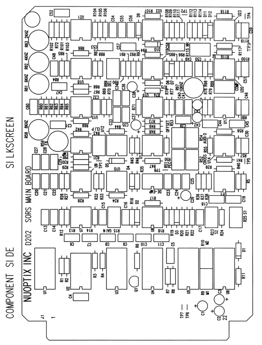
15 TRACK PLACEMENT This section will require a series of darkroom development tests. On the PC board layout diagram you will notice four trimpots labeled S1, S2, M1 and M2. Trimpots S1 and S2 displace the light valve ribbons while the unit is in the Stereo mode. Trimpots M1 and M2 displace the light valve ribbons while in the Mono mode. Trimpots S1 and M1 move the ribbons that are closest to the picture area of the film while S2 and M2 move the ribbons that are closest to the sprocket holes. Ribbon positions can be quickly and accurately set using the front panel meters to measure how far a ribbon is displaced. With the front panel 10 turn BIAS controls reduced to zero and the rotary mode switch set to BIAS, the meters will accurately read the ribbon spacing if the SETUP pots on the front panel have been properly adjusted to slack spacing reading (See Operating Instructions). Now the meter will accurately reflect any movements of the individual ribbons made by the ribbon placement trimpots. One must first determine how much and in which direction each ribbon needs to be moved using a film development test. The appropriate internal placement trimpots can be adjusted, while observing the front panel meters, to gauge the resultant displacements. This will provide rapid and accurate positioning of the track edges. Track placement should be verified by a final photographic development test. Remember that 1 mil of movement will equal 1 mil of the meter reading; i.e., if you need to move 2 mils and the slack reading is 18.0, you should adjust to read either 16.0 or 20.0 depending on the direction you need to move the ribbon. -11-
16 SIZE ADJUSTMENT Apply an 80% signal at 400Hz and verify the total recorded modulation as determined using the formula on the page titled How to Measure % Modulation. R54 should be adjusted (by reading the level at TP5 on the D202 Board) so that the modulation measured on the film corresponds exactly to the meter reading in the RECORD position. To figure out how much to adjust, after measuring the amount of modulation according to the formula on the page How to Measure % Modulation, divide 80 by the % of modulation, then use the following formula: DB=20*Log(80/%mod) An example: Using the same result in the page titled How to Measure % Modulation which is 77.8%, 20*Log(80/77.8)= , so you would raise the level.24 DB again as read on TP5 D202 Board. -12-
17 HOW TO MEASURE % MODULATION ON 35mm DUAL BILATERAL OPTICAL TRACKS -13-
18 -14-
19 LIGHT VALVE EQUALIZATION Check to see that film loss EQ dip switches labeled PRE-EMP and DE-EMP are set to OPEN (i.e. flat or no equalization). Toggle the recording lamp to OPERATE and set to nominal current. Rotate the mode switch to the SETUP position and adjust the SETUP controls for slack spacing meter reading. Advance the mode switch to the BIAS position and increase the BIAS controls on the front panel for an 8 mil bias line as indicated on the front panel meter. Advance the mode switch to the RECORD position and apply a 50% signal at 400Hz. With the DIRECT/P.E.C. toggle switch in the P.E.C. position, increase the MONITOR control for a 0 dbm level on the monitor output. Carefully sweep the input frequency, making sure that the input level remains constant, and adjust the light valve equalization internal trimpots to achieve a flat response as monitored on the P.E.C. monitor output. The reduced signal and bias levels are used to assure that the light valve does not clash during the equalization procedure. The 2KHZ, 4KHZ and 6KHZ are boost and cut filters with midrange being flat. The 8KHZ (R58) is a cut only filter. The 8KHZ filter has a frequency trim control F8 (R59) with midrange being around 8.5 KHZ. The Q of this filter is similar to that of the light valve. Setting the notch frequency of the 8KHZ filter to just above the light valve resonance frequency, say 9KHZ, results in the most accurate equalization. The 10KHZ (R78) is a boost only filter. -15-
20 LAMP BALANCE Optical sound track negatives must be properly exposed to assure crossmodulation distortion cancellation. This is accomplished by preparing cross- modulation tests for each laboratory at which sound track negatives are to be made. In addition, the two tracks of a Stereo Optical or dual bilateral optical sound track must be of equal density. Hand development test at the recording studio may be used to assure this balance of density. The photoelectric monitoring system on the SORS is very helpful in achieving lamp balance, which is changed by moving the record lamp horizontally. You will note that with the SORS in the SETUP position the meters read the amount of light exposing the two tracks. As the lamp is moved horizontally the displayed numbers will change. You will note that there is a simple relationship between the meter readings and the densities measured on the exposed negative and that this may be used to balance the lamps by monitoring the meters while moving the lamp. You can set the SETUP pots to read exactly what your density readings are, making sure you put the picture side density reading on the Left meter. the simply adjust until they read the same. This is explained also in the Camera manual. -16-
21 FILM LOSS EQUALIZATION After all the calibration procedures are complete, film loss EQ dip switches labeled PRE-EMP and DE-EMP should be set. PRE-EMP is for recording preemphasis and DE-EMP is for monitor deemphasis. Both are complimentary to each other and should therefore always be set in the same condition. Refer to the SORS PRINT LOSS EQUALIZATION curves to select the appropriate position. Position 1 or 2 with the 680pf capacitor is recommended for 35mm recording. -17-
22 -18-
23 P.E.C. AMPLIFIER ADJUSTMENTS Unplug the recording lamp from the back panel of the SORS. Rotate the mode switch to the SETUP position and rotate the SETUP pot on the front panel fully clockwise. Adjust the OFFSET pot (R53) so that the front panel meters read zero. (Caution: The PEC offset can be effected if bright light is allowed to fall on the visual track window. The window size has been reduced to minimize the problem but care should still be exercised.) Reconnect the recording lamp and set to the nominal recording lamp current. Adjust the SETUP controls for the proper slack ribbon spacing readings. Rotate the mode switch to BIAS and adjust for a 1.5 mil bias line. Change to RECORD mode and adjust the input to 80% at 400 Hz. With the DIRECT/P.E.C. in the DIRECT position, adjust the MONITOR level control on the front panel for +10 dbm at TP8. Now toggle the switch to the P.E.C. position and adjust the PEC trimpots (R51) for +10 dbm. This adjustment matches the direct and P.E.C. levels. Connect the input to the LEFT channel only. Adjust CROSS (R52) for minimum signal appearing at TP8 of the right channel board. Connect the input to the RIGHT channel only and adjust CROSS (R52) for minimum signal appearing at TP8 of the left channel board. This adjustment cancels any crosstalk that may have accumulated in the optical system. -19-
24 PIN OUT CONNECTS FOR THE SORS AND THE AOS 1. Left, Right & Mono Signal Inputs - 3 pin female XLR Pin 1 - Analog Common Pin 2 - High Pin 3 - Low 2. Left & Right Channel Monitor Outputs - 3 pin male XLR Pin 1 - No Connect Pin 2 - High Pin 3 - Analog Common 3. Optical Preamplifier - 5 pin male XLR on chassis PREAMP Pin 1 - Right Input Pin V Supply Pin 3 - Analog Common Pin V Supply Pin 5 - Left Input - E8 E5 E6 E7 E9 4. Light Valve Output - 5 pin female XLR on chassis LV TERMINALS Pin 1 - Left - (Sprocket Side) Pin 2 - Left + (Picture Side) Pin 3 - Analog Common Pin 4 - Right - (Sprocket Side) Pin 5 - Right + (Picture Side) Remote Meter Output - 4 pin female XLR on chassis Pin 1 - Left + Output Pin 2 - Analog Common Pin 3 - Analog Common Pin 4 - Right + Output 6. Aux Power - 6 pin female XLR on chassis (SORS Input) (AOS Output) Pin 1 Pin V Supply Pin 2 Pin V Supply Pin 3 Pin 3 - Audio Common Pin 4 Pin 4 - Digital Ground Pin 5 Pin Volts 7. Aux Control - 4 pin male XLR on chassis Pin 1 - Aux Signal Generator Audio Pin 2 - Aux Signal Generator On/Off 8. Lamp Output - 4 pin female XLR on chassis Pin 1 - Low Side Pin 2 - Low Side Pin 3 - High Side Pin 4 - High Side -20-
25 -21-
26 -22-
27 -23-
28 -24-
29 -25-
30 -26-
31 -27-
32 -28-
33 -29-
34 -30-
35 -31-
36 -32-
Westrex RA1713B Auxiliary Record Electronics
 Westrex RA1713B Auxiliary Record Electronics INTRODUCTION The RA-1713B is an auxiliary electronics system for use with the Westrex RA- 1712B. It comprises a current regulated, digital readout, recorder
J R Sky, Inc. Cross-Modulation Distortion Analyzer
 J R Sky, Inc. Cross-Modulation Distortion Analyzer J R Sky, Inc. 505 Evening Star Lane Bozeman, Montana 59715 USA Tel: +1.406-582-8154 email: nuoptix@jrsky.com web: www.jrsky.com revised: November 29,
clipping; yellow LED lights when limiting action occurs. Input Section Features
 ELX-1A Rack-Mount Mic/Line Mixer Four inputs, one output in a single rack space Very-highery-high-quality audio performance High reliability Extensive filtering circuitry and shielding protect against
OWNERS MANUAL LUNATEC V3 MICROPHONE PREAMPLIFIER AND A/D CONVERTER
 OWNERS MANUAL LUNATEC V3 MICROPHONE PREAMPLIFIER AND A/D CONVERTER LUNATEC 35 +48 35 +48 30 40 30 40 0 25 45 25 45 3 192 1 1 6 176.4 20 50 20 50 9 96 12 PEAK 88.2 55 55 RESET 48 10 60 2 10 60 2 21 44.1
MIDAS Venice Pin-Assignments Page 1 / 3 Mono-Channel-PCB Stereo- / Master - PCB CN 1 circuit diagram number CN 6 circuit diagram number CN
 MIDAS Venice Pin-Assignments Page 1 / 3 Mono-Channel-PCB 81346 Stereo- / Master - PCB 82230 CN 1 circuit diagram number CN 6 circuit diagram number CN 7 circuit diagram number CN 1 circuit diagram number
Summit Audio Model TLA-50 Tube Leveling Amplifier
 Summit Audio Model TLA-50 Tube Leveling Amplifier ATTACK FAST SLOW MEDIUM 3 4 5 6 7 TUBE LEVELER 40 60 80 100 VU 3 4 5 6 TLA-50 7 FAST SLOW RELEASE OUTPUT RED. METER 2 1 0 10 GAIN 9 8 7 5 3 1 0 1 2 +3
T L Audio. User Manual C1 VALVE COMPRESSOR. Tony Larking Professional Sales Limited, Letchworth, England.
 T L Audio User Manual C1 VALVE COMPRESSOR Tony Larking Professional Sales Limited, Letchworth, England. Tel: 01462 490600. International +44 1462 490600. Fax: 01462 490700. International +44 1462 490700.
12 Channel Media Splitter MS12 Mk2 User manual
 12 Channel Media Splitter MS12 Mk2 User manual 01. 12 Channel Media Splitter MS12 Mk2 An audio distribution amplifier primarily designed to feed multiple ENG cameras from a single lectern microphone at
RMX-44 & RMX-62 MIXING MATRIX. Installation & Operation Manual
 RMX-44 & RMX-6 MIXING MATRIX Installation & Operation Manual TABLE OF CONTENTS RMX-44 & RMX-6 INTRODUCTION... RMX-44 CALLOUTS... RMX-44 BLOCK DIAGRAM... RMX-6 CALLOUTS... 4 RMX-6 BLOCK DIAGRAM... 5 RMX-44
bel canto SEP2 Single Ended Triode Tube Preamplifier User's Guide and Operating Information
 bel canto SEP2 Single Ended Triode Tube Preamplifier User's Guide and Operating Information Bel Canto Design 212 Third Avenue North, Suite 274 Minneapolis, MN 55401 USA Phone: 612 317.4550 Fax: 612.359.9358
Natural-sounding telephone audio... Hybrids
 Natural-sounding telephone audio... Hybrids ... for broadcast, conferencing and public address About Comrex DH Series Digital Telephone Hybrids When you want to present, broadcast, or record a telephone
3124mb+ All Discrete 4 Channel Mic/Instrument Preamplifier with Stereo Mixer Operator s Manual
 3124mb+ All Discrete 4 Channel Mic/Instrument Preamplifier with Stereo Mixer Operator s Manual Written by Carl J Houde 2015 Table of Contents 1.0 Introduction... 3 2.0 Overview... 4 2.1 3124mb+ Features
Pre1. Balanced Control Preamplifier. User's Guide and Operating Information
 Pre1 Balanced Control Preamplifier User's Guide and Operating Information Bel Canto Design 212 Third Avenue North Suite 345 Minneapolis, MN 55401 Phone: (612) 317.4550 Fax: (612) 359.9358 Email: Info@BelCantoDesign.com
MODEL PA II-R (1995-MSRP $549.00)
") F O R T H E L O V E O F M U S I C MODEL PA II-R (1995-MSRP $549.00) OWNER'S MANUAL AND INSTALLATION GUIDE INTRODUCTION To aid in the exciting and custom installs which installers are performing all over
F O R T H E L O V E O F M U S I C MODEL PA II-R (1995-MSRP $549.00) OWNER'S MANUAL AND INSTALLATION GUIDE INTRODUCTION To aid in the exciting and custom installs which installers are performing all over
RoHS. Atma-Sphere Music Preamplifier. model P-2 OWNER'S MANUAL. Please study this document carefully before using equipment
 1742 Selby Av. St. Paul, MN 55104 651 690 2246 atma sphere.com Atma-Sphere Music Preamplifier model P-2 OWNER'S MANUAL Please study this document carefully before using equipment RoHS CONGRATULATIONS!
PHASE HL SEL 1 HL SEL 2 EXT MONITOR ELAN ELAN ELAN ELAN MLM-201 HLM-201 HLM-201 TBM-201 MLM-201 GAIN GAIN GAIN LEFT GAIN RIGHT SELECT SELECT SELECT
 Audio Promotional Information "Kestrel-12" and "Kestrel-16" Modular Dual Channel Stereo "On-Air" Mixer "Kestrel-12" "KESTREL-12" HL SEL 1 HL SEL 2 EXT MITOR VU O'LOAD PHASE VU VU AUDIO AIR DELAY DUMP TLM-201
32 Channel CPCI Board User Manual
 0 Sections Page 1.0 Introduction 1 2.0 Unpacking and Inspection 1 3.0 Hardware Configuration 1 4.0 Board Installation 5 5.0 I/O Connections and the Front Panel 5 5.1 Front Panel Layout 5 5.2 Input and
OTM-3000-I FREQUENCY AGILE TELEVISION MODULATOR PAL I STANDARD INSTRUCTION MANUAL
 OTM-3000-I FREQUENCY AGILE TELEVISION MODULATOR PAL I STANDARD INSTRUCTION MANUAL Phone: (209) 586-1022 (800) 545-1022 Fax: (209) 586-1026 E-Mail: salessupport@olsontech.com 025-000137 REV B www.olsontech.com
Output Board - v2* 4.1 Overview. 4.2 Audio Circuitry Program and Audition Outputs
 Output Board - v2* 4.1 Overview This circuit board provides the following console functions: Line output amplification Cue amplification Headphone amplification External Inputs (balanced *) Monitor sends
110LP MOON Series. Phono Preamplifier. Owner s Manual
 Phono Preamplifier Owner s Manual Owner s Manual I Table of Contents Introduction 4 Unpacking 5 Installation & Placement 5 Circuit Board Layout s 6 Internal Adjustments 7 Rear Panel Connections 8 Operating
OPERATION NOTES FOR PSIDEX AUDIO PGP-1A PRE-AMPLIFIER DESCRIPTION INSTALLATION
 OPERATION NOTES FOR PSIDEX AUDIO PGP-1A PRE-AMPLIFIER DESCRIPTION The Psidex Audio Laboratory PGP- 1A is a vacuum tube based microphone preamp and program line amplifier designed to provide solid, robust
XO-231 USER S MANUAL. Crossover ENGLISH
 XO-231 Crossover ENGLISH USER S MANUAL IMPORTANT SAFETY INSTRUCTIONS For your own safety you should read this section in full first! Risk of electrical shock! Connect the device only to a properly wired
Chameleon Labs Model 7720
 Chameleon Labs Model 7720 Stereo Compressor Owner s Manual 704 228 th Avenue NE, # 826 Sammamish, WA 98074 206-264-7602 www.chameleonlabs.com Revision C - December, 2007 UNPACKING AND INSPECTION Carefully
+41 * 2 db. GENERAL The Shure M675 Broadcast Production Master is designed for use in conjunction with a Shure M67 or
 2 2 2 HARTREY AVE., EVANSTON, IL. 6 0 2 0 4 U.S.A. GENERAL The Shure M675 Broadcast Production Master is designed for use in conjunction with a Shure M67 or M67-2E Professional Microphone Mixer, M63 Audio
ANALOG RADIO MIXER. Flexible. Affordable. Built To Last.
 ANALOG RADIO MIXER Flexible. Affordable. Built To Last. Audioarts AIR-4 A N A L O G R A D I O M I X E R At Audioarts, value engineering is straightforward: Define the features our customers require. Design
Noise Detector ND-1 Operating Manual
 Noise Detector ND-1 Operating Manual SPECTRADYNAMICS, INC 1849 Cherry St. Unit 2 Louisville, CO 80027 Phone: (303) 665-1852 Fax: (303) 604-6088 Table of Contents ND-1 Description...... 3 Safety and Preparation
DLM471S-5.1 MULTICHANNEL AUDIO LEVEL MASTER OPERATION MANUAL IB B. (Mounted in RMS400 Rack Mount & Power Supply) (One of 4 Typical Cards)
 (One of 4 Typical Cards)") DLM471S-5.1 (Mounted in RMS400 Rack Mount & Power Supply) MULTICHANNEL AUDIO LEVEL MASTER (One of 4 Typical Cards) OPERATION MANUAL IB6432-02B TABLE OF CONTENTS PAGE 1.0 GENERAL DESCRIPTION 2 2.0 INSTALLATION
DLM471S-5.1 (Mounted in RMS400 Rack Mount & Power Supply) MULTICHANNEL AUDIO LEVEL MASTER (One of 4 Typical Cards) OPERATION MANUAL IB6432-02B TABLE OF CONTENTS PAGE 1.0 GENERAL DESCRIPTION 2 2.0 INSTALLATION
Owner s Manual PRE1. v1.2. Triode Class A Line Preamplifier
 Owner s Manual PRE1 Triode Class A Line Preamplifier www.lab12.gr v1.2 Table of Contents It is yours Features Installation & Placement Front Panel Rear Panel Remote Control Main connections For the safety
LCM-6550 TRIPLE TELEVISON MODULATOR INSTRUCTION MANUAL
 LCM-6550 TRIPLE TELEVISON MODULATOR INSTRUCTION MANUAL Phone: (209) 586-1022 (800) 545-1022 Fax: (209) 586-1026 E-Mail: salessupport@olsontech.com 025-000244 REV E www.olsontech.com 6/21/01 LCM-6550 TRIPLE,
R2001A/B/C Service Monitor Alignment Sections
 R2001A/B/C Service Monitor Alignment Sections R2001A Depot Alignment Notes R2001A Alignment Section A12 FRNT PNL INTERFACE A3 SCOPE/DVM CONTRC)L SINAD IN 3 ( 6 3 1 KHz NOTCH FIL DET»
LCM-550x12 12 CHANNEL TELEVISION MODULATOR SYSTEM INSTRUCTION MANUAL
 LCM-550x12 12 CHANNEL TELEVISION MODULATOR SYSTEM INSTRUCTION MANUAL Phone: (209) 586-1022 (800) 545-1022 Fax: (209) 586-1026 E-Mail: salessupport@olsontech.com 025-000329 REV C www.olsontech.com 6/1/01
508 Phono Preamplifier. Boulder Amplifiers, Inc. 255 S. Taylor Ave. Louisville, CO (303) /1/2018 Rev. 1.
 /1/2018 Rev. 1.") 508 Phono Preamplifier 6/1/2018 Rev. 1.0 P/N: 91053 Boulder Amplifiers, Inc. 255 S. Taylor Ave. Louisville, CO 80027 (303) 449-8220 www.boulderamp.com About About Boulder Amplifiers, Inc. Boulder was founded
508 Phono Preamplifier 6/1/2018 Rev. 1.0 P/N: 91053 Boulder Amplifiers, Inc. 255 S. Taylor Ave. Louisville, CO 80027 (303) 449-8220 www.boulderamp.com About About Boulder Amplifiers, Inc. Boulder was founded
Introducing the New Daking Console
 Introducing the New Daking Console Daking The Console that can change from a Legacy Bussing scheme to DAW Direct Routing with the touch of a button. Features: Class A Circuitry Transformer Coupled Pre-Amps
CLOCKAUDIO. MR88 Automatic Microphone Mixer. Version 4.2
 CLOCKAUDIO MR88 Automatic Microphone Mixer Version 4.2 Clockaudio Limited,22 Arnside Road WATERLOOVILLE Hampshire. UK Tel : +44 (0)2392 251193 Fax : +44 (0)2392 251201 Email : sales@clockaudio.co.uk CONTENTS
TDM 24CX-2 24CX-3 24CX-4 ELECTRONIC CROSSOVER OWNER S MANUAL A U D I O
 TDM A U D I O 24CX-2 24CX-3 24CX-4 ELECTRONIC CROSSOVER OWNER S MANUAL TDM AUDIO INC. 7270 BELLAIRE AVE. NORTH HOLLYWOOD, CA 91605 (818) 765-6200 TDMAUDIO.COM IMPORTANT! *** Read Before Using *** CAUTION:
Table of Contents. Introduction 2 C valve Features 3. Controls and Functions 4-5 Front Panel Layout 4 Rear Panel Layout 5
 Safety Instructions Table of Contents Introduction 2 C valve Features 3 Controls and Functions 4-5 Front Panel Layout 4 Rear Panel Layout 5 Operating the C valve 6-13 Setting Up the C valve 6-7 Setting
TL AUDIO M4 TUBE CONSOLE
 TL AUDIO M4 TUBE CONSOLE USER MANUAL TL AUDIO M4 TUBE CONSOLE M4 INTRODUCTION... 3 M4 MIXER TECHNICAL SPECIFICATION... 4 Mic Input:... 4 Line Input:... 4 Phase Rev:... 4 High Pass Filter:... 4 Frequency
INTRODUCTION PRODUCT CONCEPT AND DESCRIPTION
 1 INTRODUCTION PRODUCT CONCEPT AND DESCRIPTION The Audio Suite is a mainframe which accepts up to ten modular sections thereby permitting individualized selection of preamplifier features and functions.
MASTR II BASE STATION 12/24V POWER SUPPLY 19A149979P1-120 VOLT/60 Hz 19A149979P2-230 VOLT/50 Hz
 Mobile Communications MASTR II BASE STATION 12/24V POWER SUPPLY 19A149979P1-120 VOLT/60 Hz 19A149979P2-230 VOLT/50 Hz CAUTION THESE SERVICING INSTRUCTIONS ARE FOR USE BY QUALI- FIED PERSONNEL ONLY. TO
The Distortion Magnifier
 The Distortion Magnifier Bob Cordell January 13, 2008 Updated March 20, 2009 The Distortion magnifier described here provides ways of measuring very low levels of THD and IM distortions. These techniques
COMREX. Specifications (preliminary)
") About STAC What are you talking about? A call-in on local politics. An interview with the winning quarterback from his hotel. An eyewitness with late-breaking news. A dedication to the one someone loves.
About STAC What are you talking about? A call-in on local politics. An interview with the winning quarterback from his hotel. An eyewitness with late-breaking news. A dedication to the one someone loves.
OTM-3550-SW FREQUENCY AGILE F.C.C. COMPATIBLE TELEVISION MODULATOR INSTRUCTION MANUAL
 FREQUENCY AGILE F.C.C. COMPATIBLE TELEVISION MODULATOR INSTRUCTION MANUAL Phone: (209) 586-1022 (800) 545-1022 Fax: (209) 586-1026 E-Mail: salessupport@olsontech.com 025-000233 REV E www.olsontech.com
Signal Conditioners. Highlights. Battery powered. Line powered. Multi-purpose. Modular-style. Multi-channel. Charge & impedance converters
 Signal Conditioners Highlights Battery powered Line powered Multi-purpose Modular-style Multi-channel Charge & impedance converters Industrial charge amplifiers & sensor simulators PCB Piezotronics, Inc.
The performance of a lifetime. Owner s Manual MOON 110LP v2 Phono Preamplifier
 The performance of a lifetime Owner s Manual MOON 110LP v2 Phono Preamplifier MOON by Simaudio simaudio.com Simaudio Ltd 1345 Newton Road, Boucherville, Québec J4B 5H2 CANADA Date Code: 20180831 01 INTRODUCTION
S0 Radio Broadcasting Mixer. June catalogue. Manufacturers of audio & video products for radio & TV broadcasters
 S0 Radio Broadcasting Mixer June 2012 catalogue Manufacturers of audio & video products for radio & TV broadcasters S0 Radio Broadcasting Mixer A simple radio mixer for novice and professional users The
THERMIONIC CULTURE. TheEarlybird 2.2. valve microphone pre-amplifier OPERATING MANUAL
 THERMIONIC CULTURE TheEarlybird 2.2 valve microphone pre-amplifier OPERATING MANUAL WARNING For your personal safety, please read this operating manual and warning thoroughly before using the equipment.
X-Four console. description. features. sound fundamentals. built to defy murphy s law. wide range of configurations
 X-Four console description If your application requires all the features and performance of a thoroughly-professional mixing console, but presents severe spacerestrictions, then the Crest Audio X-Four
CFX 12 (12X4X1) 8 mic/line channels, 2 stereo line channels. CFX 16 (16X4X1) 12 mic/line channels, 2 stereo line channels
 8 mic/line channels, 2 stereo line channels. CFX 16 (16X4X1) 12 mic/line channels, 2 stereo line channels") COMPACT CFX MIXERS COMPACT SOUND REINFORCEMENT MIXERS WITH EFX FOR THE GIGGING MUSICIAN THREE MODELS CFX 12 (12X4X1) 8 mic/line channels, 2 stereo line channels CFX 16 (16X4X1) 12 mic/line channels, 2
COMPACT CFX MIXERS COMPACT SOUND REINFORCEMENT MIXERS WITH EFX FOR THE GIGGING MUSICIAN THREE MODELS CFX 12 (12X4X1) 8 mic/line channels, 2 stereo line channels CFX 16 (16X4X1) 12 mic/line channels, 2
PROFESSIONAL 2 CHANNEL SOLID-STATE MIC / LINE PREAMPLIFIER USER S MANUAL
 PROFESSIONAL 2 CHANNEL SOLID-STATE MIC / LINE PREAMPLIFIER USER S MANUAL SAFETY INSTRUCTIONS This symbol, wherever it appears, alerts you to important operating and maintenance instructions in the accompanying
Element 78 MPE-200. by Summit Audio. Guide To Operations. for software version 1.23
 Element 78 MPE-200 by Summit Audio Guide To Operations for software version 1.23 TABLE OF CONTENTS IMPORTANT SAFETY AND GROUNDING INSTRUCTIONS COVER 1. UNPACKING AND CONNECTING...3 AUDIO CONNECTIONS...4
COHERENCE ONE PREAMPLIFIER
 COHERENCE ONE PREAMPLIFIER OWNER S MANUAL TABLE OF CONTENTS Introduction Features Unpacking Instructions Installation Phono Cartridge Loading Basic Troubleshooting Technical Specifications Introduction
222 HARTREY AVE., EVANSTON, IL U.S.A. AREA CODE 312/ CABLE: SHUREMlCRO. Copyright 1973, Shure Brothers Inc.
 222 HARTREY AVE., EVANSTON, IL. 60204 U.S.A. AREA CODE 312/328-9000 CABLE: SHUREMlCRO General: The Shure Model M63 Audio Master is a unit designed to give maximum flexibility in the control of volume,
DIGITAL SPEAKER MANAGEMENT UK
 DSM2-6mkII DIGITAL SPEAKER MANAGEMENT 170.659UK Features 96kHz sampling frequency, 32-bit A/D and D/A converter, 24-bit DSP processor Input channel: 6-band parametric EQ, Delay, Polarity Output channel:
FREQUENCY CONVERTER HIGH-PERFORMANCE OUTDOOR BLOCK UP AND DOWNCONVERTERS. Narda-MITEQ 1 FEATURES OPTIONS
 FREQUENCY CONVERTER HIGH-PERFORMANCE OUTDOOR BLOCK UP AND DOWNCONVERTERS Standard Configuration Vertical Mount Option FEATURES Antenna mount, weatherproof to IP-65 Automatic 5/10 MHz internal/external
CP1 OAD. Owner s Manual. Stereo Control Preamplifier. Ultrafidelity
 OAD Ultrafidelity CP1 Stereo Control Preamplifier Owner s Manual Contents Section Page No. Introduction........................................................................ 1 Warnings.................................................................................
FREQUENCY CONVERTER. MULTIPLE OUTPUT WIDEBAND Ku AND Ka DOWNCONVERTERS. Narda-MITEQ FEATURES OPTIONS
 MULTIPLE OUTPUT WIDEBAND Ku AND Ka DOWNCONVERTERS FEATURES Small weather resistant enclosure Automatic 5/10 MHz internal/external reference selection 10/100 Base-T Ethernet and RS-485/RS-422 remote control
LEAMING INDUSTRIES MTS-4A BTSC STEREO GENERATOR
 LEAMING INDUSTRIES MTS-4A BTSC STEREO GENERATOR INSTRUCTION BOOK IB 090941-01 C ALL ENGINEERING DESIGNS, DRAWINGS AND DATA CONTAINED HEREIN ARE PROPRIETARY. NO PART OF THIS BOOK MAY BE COPIED OR OTHERWISE
LEVEL ADJUST POWER Shiloh Road Alpharetta, Georgia (770) FAX (770) Toll Free
 FAX (770) Toll Free") Instruction Manual Model 1200-07 Amplifier September 2010 Rev A MONITOR J1 LEVEL ADJUST POWER MODEL 1200 AMPLIER CROSS TECHNOLOGIES, INC. Data, drawings, and other material contained herein are proprietary
Instruction Manual Model 1200-07 Amplifier September 2010 Rev A MONITOR J1 LEVEL ADJUST POWER MODEL 1200 AMPLIER CROSS TECHNOLOGIES, INC. Data, drawings, and other material contained herein are proprietary
Boulder 1010 Preamplifier
 Boulder 1010 Preamplifier Owners Manual 10/1/03 Boulder Amplifiers, Inc. 3235 Prairie Ave. Boulder, CO 80301 www.boulderamp.com APPENDIX RECORDING BOULDER LINK PROGRAMMING REMOTE CONTROL OPERATION GETTING
MAXTECH, Inc. BRC-1000 Series. C-Band Redundant LNB Systems. Technology for Communications. System Block Diagrams
 MAXTECH, Inc. Technology for Communications BRC-1000 Series C-Band Redundant LNB Systems Introduction Redundant LNB systems minimize system downtime due to LNB failure by providing a spare LNB and an automatic
AMEK SYSTEM 9098 DUAL MIC AMPLIFIER (DMA) by RUPERT NEVE the Designer
 by RUPERT NEVE the Designer") AMEK SYSTEM 9098 DUAL MIC AMPLIFIER (DMA) by RUPERT NEVE the Designer If you are thinking about buying a high-quality two-channel microphone amplifier, the Amek System 9098 Dual Mic Amplifier (based on
AMEK SYSTEM 9098 DUAL MIC AMPLIFIER (DMA) by RUPERT NEVE the Designer If you are thinking about buying a high-quality two-channel microphone amplifier, the Amek System 9098 Dual Mic Amplifier (based on
5.1 + Stereo Monitor Controller
 Broadcast Devices, Inc. Technical Reference Manual 5.1 + Stereo Monitor Controller Broadcast Devices, Inc. 2066 E. Main Street Cortlandt Manor, NY 10567 Tel. (914) 737-5032 Fax. (914) 736-6916 World Wide
LEVEL ADJUST POWER Shiloh Road Alpharetta, Georgia (770) FAX (770) Toll Free
 FAX (770) Toll Free") Instruction Manual Model 1200-75 Amplifier August 2012, Rev. A LEVEL ADJUST POWER MODEL 1200 AMPLIFIER CROSS TECHNOLOGIES, INC. Data, drawings, and other material contained herein are proprietary to Cross
Instruction Manual Model 1200-75 Amplifier August 2012, Rev. A LEVEL ADJUST POWER MODEL 1200 AMPLIFIER CROSS TECHNOLOGIES, INC. Data, drawings, and other material contained herein are proprietary to Cross
FREQUENCY CONVERTER 1/3 RACK-MOUNTED BLOCK CONVERTER. Narda-MITEQ FEATURES OPTIONS. Unit shown with Option 17. Unit shown without Option 17
 1/3 RACK-MOUNTED BLOCK CONVERTER Unit shown with Option 17 Unit shown without Option 17 FEATURES Automatic 5/10 MHz internal/external reference selection with a 0.1 Hz nominal bandwidth clean-up loop Gain
ROSS VIDEO LIMITED PAA Programmable Audio Amplifier USER MANUAL PAA-01-MNL Issue 1
 ROSS VIDEO LIMITED PAA-7803 Programmable Audio Amplifier USER MANUAL 7803-PAA-01-MNL Issue 1 PAA-7803 Programmable Audio Amplifier User s Manual Ross Part Number: 7803-PAA-01-MNL Document Issue: 1 Printing
2002 Martin Professional A/S, Denmark.
 Freekie user manual 2002 Martin Professional A/S, Denmark. All rights reserved. No part of this manual may be reproduced, in any form or by any means, without permission in writing from Martin Professional
Table of Contents. Read This First.2. Introduction by Jim Fosgate...3. Unpacking..4. Tubes and Tube shield Installation 5. Product Placement...
 Owner s Manual Table of Contents Read This First.2 Introduction by Jim Fosgate...3 Unpacking..4 Tubes and Tube shield Installation 5 Product Placement...6 Connecting your Fosgate Signature..7 Phono stage
LEGEND L6. # Designed and engineered in the U.K. 6 Modules Just 3U
 500 series portable chassis for 6 single-width modules Advanced audio routing reduces cabling complexity Audio output link switches provide cable-free daisy-chain connections between modules Compressor
MCM-20.4 PRELIMINARY USER GUIDE v1.1
 MCM-20.4 PRELIMINARY USER GUIDE v1.1 2017 All the documentation included in this manual is copyrighted by Heritage Audio S.L. All rights are reserved. No part of this manual may be reproduced, copied,
Recording to Tape (Analogue or Digital)...10
...10") c o n t e n t s DUAL MIC-PRE Green Dual Mic Pre (introduction).............................4 Section (i): Setting Up Power Connections...........................................4 Power Supply................................................5
c o n t e n t s DUAL MIC-PRE Green Dual Mic Pre (introduction).............................4 Section (i): Setting Up Power Connections...........................................4 Power Supply................................................5
Version 1.10 CRANE SONG LTD East 5th Street Superior, WI USA tel: fax:
 -192 HARMONICALLY ENHANCED DIGITAL DEVICE OPERATOR'S MANUAL Version 1.10 CRANE SONG LTD. 2117 East 5th Street Superior, WI 54880 USA tel: 715-398-3627 fax: 715-398-3279 www.cranesong.com 2000 Crane Song,LTD.
MODEL OTM-4870 FREQUENCY AGILE 870MHz F.C.C. COMPATIBLE TELEVISION MODULATOR
 MODEL OTM-4870 FREQUENCY AGILE 870MHz F.C.C. COMPATIBLE TELEVISION MODULATOR USERS MANUAL Phone: (209) 586-1022 (800) 545-1022 Fax: (209) 586-1026 E-Mail: salessupport@olsontech.com 025-000412 Rev. B www.olsontech.com
Video-Audio Processors
 Video-Audio Processors Kramer Electronics offers several Video-Audio Processors for image and sound enhancement in production and duplication studios, as well as for any other demanding application. The
Technical Instruction Manual
 Technical Instruction Manual DORROUGH STEREO SIGNAL TEST SET Model 0 STEREO SIGNAL TEST SET MODEL 0 -/ - -/- -0/ 0 / 0 - - - - -0 STEREO SUM/DIFF. -. - -0-6. - - -0 - - 0 - - - - 0 0 6 - - 0 0 0. -. -
MULTIDYNE INNOVATIONS IN TELEVISION TESTING & DISTRIBUTION DIGITAL VIDEO, AUDIO & DATA FIBER OPTIC MULTIPLEXER TRANSPORT SYSTEM
 MULTIDYNE INNOVATIONS IN TELEVISION TESTING & DISTRIBUTION INSTRUCTION MANUAL DVM-1000 DIGITAL VIDEO, AUDIO & DATA FIBER OPTIC MULTIPLEXER TRANSPORT SYSTEM MULTIDYNE Electronics, Inc. Innovations in Television
BEFORE PROCEEDING WITH COMPLETE UNPACKING AND SETUP, CONSULT UNPACKING AND INSPECTION INSTRUCTIONS ON PAGE 8. Model LA 4 COMPRESSOR/LIMITER
 BEFORE PROCEEDING WITH COMPLETE UNPACKING AND SETUP, CONSULT UNPACKING AND INSPECTION INSTRUCTIONS ON PAGE 8 Model LA 4 COMPRESSOR/LIMITER EFFECTIVE WITH SERIAL +3196 United Recording Electronics Industries
SM12 & SM16 STEREO MIC/LINE MIXING CONSOLES OPERATION MANUAL
 SM12 & SM16 STEREO MIC/LINE MIXING CONSOLES OPERATION MANUAL INTRODUCTION AND CONTENTS The Australian Monitor Pro Series SM12 and SM16 stereo console mixers are designed to be compact, ultra low noise
SONOSAX SX-PR OPERATOR'S MANUAL
 SONOSAX SX-PR OPERATOR'S MANUAL Manual copyright 1989 - Gary J. Louie Sonosax is a trademark of Jacques Sax Edition 2.1 OVERVIEW The Sonosax SX-PR series portable stereo audio mixers are designed for jobs
MX-206 Stereo Microphone Mixer. Operating Manual
 MX-206 Stereo Microphone Mixer Operating Manual ASHLY AUDIO INC. 847 Holt Road Webster, NY 14580-9103 Phone: (585) 872-0010 Toll-Free: (800) 828-6308 Fax: (585) 872-0739 www.ashly.com Operating Manual
Since Stereo Preamplifier. An introduction to the technology within the Boulder 1110 Stereo Preamplifier.
 Since 1984 1110 Stereo Preamplifier An introduction to the technology within the Boulder 1110 Stereo Preamplifier. Welcome Basic Design What constitutes a high-performance preamplifier? The feel of the
MTP 15HD A Series MTP - MINI TWISTED PAIR TRANSMITTERS & RECEIVERS FOR COMPUTER VIDEO & AUDIO. Twisted Pair.
 Twisted Pair MTP 15HD A Series MTP - MINI TWISTED PAIR TRANSMITTERS & RECEIVERS FOR COMPUTER & AUDIO n Sends and receives high resolution video and summed mono audio signals 600 feet (185 meters) or more
LP-PAN Preamp Kit Assembly Manual
 LP-PAN Preamp Kit Assembly Manual December 2010 TelePost Incorporated Rev. A9 1 Table of Contents Introduction... 2 Specifications... 3 Parts List... 4 Assembly... 5 Checkout / Schematic... 9 Introduction
Model /29S RF Splitter
 Instruction Manual Model 1584-29/29S RF Splitter March 2013, Rev. 0 LNB VOLTAGE A B MODEL 1584 COMBINER CROSS TECHNOLOGIES INC. GND+DC ON Data, drawings, and other material contained herein are proprietary
What are you talking about...
 What are you talking about... STAC Key STAC Features Dual, high performance digital hybrids for reliable, natural sounding caller audio, even when conferencing. Configurations for six and 12 phone lines.
USER GUIDE. DM Engineering Multi Station Relay Adapter (MSRA and MSRA-RM) Version DM Engineering
 Version DM Engineering") USER GUIDE DM Engineering Multi Station Relay Adapter (MSRA and MSRA-RM) Version 1.35 DM Engineering 2174 Chandler St. Camarillo, CA 91345-4611 805-987-7881 800-249-0487 www.dmengineering.com Overview:
USER GUIDE DM Engineering Multi Station Relay Adapter (MSRA and MSRA-RM) Version 1.35 DM Engineering 2174 Chandler St. Camarillo, CA 91345-4611 805-987-7881 800-249-0487 www.dmengineering.com Overview:
Owner s Manual. Model PH8 Phono Preamplifier
 Owner s Manual Model PH8 Phono Preamplifier 2 Contents Model PH8 Phono Preamplifier Illustrations 4 Preface 5 Warnings 5 Packaging 5 Front Panel Controls 5 6 Remote Control Functions 6 Connections 6 Installation
CR-6 MIXER USER MANUAL ENGLISH. Order Code: MIXE01
 CR-6 MIXER P R O F E S S I O N A L 1 9 R A C K M I X E R Order Code: MIXE01 w w w. p r o l i g h t. c o. u k USER MANUAL ENGLISH WARNING FOR YOUR OWN SAFETY, PLEASE READ THIS USER MANUAL CAREFULLY BEFORE
2 MHz Lock-In Amplifier
 2 MHz Lock-In Amplifier SR865 2 MHz dual phase lock-in amplifier SR865 2 MHz Lock-In Amplifier 1 mhz to 2 MHz frequency range Dual reference mode Low-noise current and voltage inputs Touchscreen data display
MclNTOSH MODEL C-4 and C-4P
 INSTRUCTION MANUAL MclNTOSH MODEL C-4 and C-4P AUDIO COMPENSATORS McINTOSH LABORATORY, INC. 320 Water St. Binghamton, N. Y. U.S.A. - 1 - INSTRUCTION MANUAL McINTOSH MODEL C-4 and C-4P AUDIO COMPENSATORS
Owner s Manual. Introduction. Features. Contents Front and rear panel... 2 Control panel... 2 Input/output panel... 6 Rear panel...
 ED MIXER Owner s Manual Introduction Thank you for purchasing the Yamaha EMX4 Powered Mixer. The EMX4 has the following features. In order to take full advantage of the EMX4 and enjoy long and trouble-free
Modula SDI Digital Video Enclosures
 Modula SDI Digital Video Enclosures This Boards & Specifications section contains specific board installation information for boards available for the following SDI Modula enclosure models: Modula Enclosure
Orfeo 30 Single Ended 845 Triode Monobloc Audio Power Amplifier User's Guide and Operating Information
 bel canto Orfeo 30 Single Ended 845 Triode Monobloc Audio Power Amplifier User's Guide and Operating Information Bel Canto Design 10250 Valley View Road, Suite 135A Eden Prairie, MN 55344 612-942-9919
MCM-8 II PRELIMINARY USER GUIDE v1.0
 MCM-8 II PRELIMINARY USER GUIDE v1.0 2018 Heritage Audio S.L. is the solely owner of the copyright of all information and drawings contained in this manual which are not to be copied or reproduced by any
DN1248PLS-FM features transformer-balancing on all outputs, and is fitted with dual redundant power supplies as standard.
 Award-winning MIDAS HERITAGE microphone preamplifier for highest signal integrity 12 channel microphone splitter with 4 transformer balanced outputs per channel Solo bus with integrated headphone amplifier
MULTIBAND 1/3 RACK-MOUNTED
 BLOCK CONVERTER FEATURES Cover multiple ITU Ku-Band regions and other combinations Automatic 5/10 MHz internal/external reference selection with a 0.1 Hz nominal bandwidth clean-up loop RS-485/RS-422 and
Owners Manual. Microphone Preamplifier and A/D Converter. Manual Rev E
 Owners Manual Microphone Preamplifier and A/D Converter Manual Rev E 2434 30th Street, Boulder, CO 80304 USA tel 303.443.7454 fax 303.444.4634 www.gracedesign.com email: info@gracedesign.com Revision D
CM SERIES. 8 Channel Monitor / Crossover. 181 Bonetti Drive San Luis Obispo, CA ph: fax:
 CM SERIES 8 Channel Monitor / Crossover 181 Bonetti Drive San Luis Obispo, CA 93401 ph: 805-549-0161 fax: 805-549-0163 e-mail:usl@uslinc.com One Year Limited Warranty USL, Inc. warrants that each product
D.W. FEARN. VT-4 Vacuum Tube LC Equalizer. Operating Instructions
 D.W. FEARN VT-4 Vacuum Tube LC Equalizer Operating Instructions HOW TO CONTACT US: Telephone: 215-692-4701 Shipping Address: Hazelrigg Industries 124 Tartan Terrace Chalfont, PA 18914 U.S.A. e-mail: support@hazelriggindustries.com
DIGITAL TELEPHONE INTERFACES
 The three Telos ONE models present superb digital telephone hybrid performance to broadcast, teleconferencing, and communications applications. Proven Telos processing technologies perform all hybrid functions.
Overview. A 16 channel frame is shown.
 Overview A 16 channel frame is shown. 22 Mono Input Channel 1 - MIC INPUT The mic input accepts XLR-type connectors and is designed to suit a wide range of BALANCED or UNBALANCED signals. Professional