Changes. Copyright. Guarantee. Trademarks. 2 R DreamScaler3 User Manual
|
|
|
- Martha Barrett
- 5 years ago
- Views:
Transcription
1
2 Changes DreamVision provides this manual as is without warranty of any kind, either expressed or implied, including but not limited to the implied warranties or merchantability and fitness for a particular purpose. DreamVision may make improvements and/or changes to the product(s) and/or the program(s) described in this publication at any time without notice. This publication could contain technical inaccuracies or typographical errors. Changes are periodically made to the information in this publication; these changes are incorporated in new editions of this publication. Copyright All right reserved. No part of this document may be copied, reproduced or translated. It shall not otherwise be recorded, transmitted or stored in a retrieval system without the prior written consent of DreamVision. Guarantee DreamVision provides a guarantee relating to perfect manufacturing as part of the legally stipulated terms of guarantee. On receipt, the purchaser must immediately inspect all delivered goods for damage incurred during transport, as well as for material and manufacturing faults. DreamVision must be informed immediately in writing of any complaints. If the purchaser or third party caries out modifications or repairs on goods delivered by DreamVision, or if the goods are handle incorrectly, in particular if the systems are commissioned operated incorrectly or if, after the transfer of risks, the goods are subject to influences not agreed upon in the contract, all guarantee claims of the purchaser will be rendered invalid. Not included in the guarantee coverage are system failures which are attributed to programs or special electronic circuitry provided by the purchaser, e.g. interfaces. Normal wear as well as normal maintenance are not subject to the guarantee provided by DreamVision either. The environmental conditions as well as the servicing and maintenance regulations specified in this manual must be complied with by the customer. Trademarks Brand and product names mentioned in this manual may be trademarks, registered trademarks or copyrights of their respective holders. All brands and product names mentioned in this manual serve as comments or examples and are not to be understood as advertising for the products of their manufactures. 2 R DreamScaler3 User Manual
3 TABLE OF CONTENTS 1.0 GETTING STARTED Introduction Document Conventions Unpacking and Inspection Display Compatibility Requirements Installation Guidelines BASIC OPERATION Front Panel Overview Rear Panel Overview... 8 Video Inputs... 8 Video Outputs... 9 Audio Inputs... 9 Audio Outputs... 9 Power Supply Input Remote Control Overview Power/Standby Buttons Curtain Button Remote Control Battery Installation Menu Navigation Info Screen Button SETUP Initial Set-Up STEP 1 - Power Up STEP 2 - Connect the scaler to your display STEP 3 - Connecting your Sources to the DreamScaler Audio Operation MENU OPTIONS Input Select Input Aspect Ratio Control Frame Aspect Ratio Active Aspect Ratio DreamScaler3 Image Mapping Panorama Zoom Pan Borders Presets Front Panel and On-Screen Displays for IAR Input Adjust Control...21 Deinterlacing PReP Overscan Line Offset Color Space Input Level VCR Mode HDMI Config Auto Input Priority Selection Audio Input AV Lip Sync Picture Controls Brightness Contrast Saturation Hue Sharpness Y/C Delay R DreamScaler3 User Manual 3
4 Chroma Filter (Auto CUE-C) Configuration Test Patterns Auto Standby LED Brightness User Mode Serial Port Rate Factory Default Software Update Information Output Setup Analog/Digital (A/D) Output Format Output Aspect Ratio Control Sync Type Color Space Output Level Framerate Conversion Border Level Gamma Correction HDCP Mode Display Profiles APPENDIX Non-Volatile Memory Settings System Settings Input / Format Settings Format settings Setting up an DreamScaler3 Using the Internal Test Patterns Determining the Correct Output Resolution for Your Display Initial Setup of the to Your Display: Display Calibration Special Equipment Needed for Display Calibration CRT Display Calibration Source Calibration Troubleshooting My DreamScaler3 shows an error message The picture has horizontal lines with the Output set to 1080p60 (or 720p60) The picture is green when I use the analog output of the DreamScaler No picture when I connect the DreamScaler3 to the HDMI input of my display.. 39 The Blue status LED blinks on the front panel of the DreamScaler The Green status LED blinks on the front panel of the DreamScaler Will I lose the settings on my DreamScaler3 if I update the software version Complete Menu Tree R DreamScaler3 User Manual

5 1.0 GETTING STARTED 1.0 GETTING STARTED 1.1 Introduction Thank you for purchasing the DreamScaler3 Video processor powered by ABT. This product delivers a level of quality among the very highest available today. We are especially pleased to bring you ABT s new VRS Precision Video Scaling II technology. This technology enables precision up conversion of standard and high definition (480i/p, 576i/p, 720p, 1080i/p) video sources and content to the native or optimum resolution of your display, delivering best in-class front-of-screen performance. Available output resolutions span from VGA up to 1080p, including the standard HDTV resolutions of 720p and 1080i. In addition to the video scaling technology the DreamScaler3 also offers a host of other innovative features, including: 4 HDMI (High Definition Multimedia Interface) inputs and 1 HDMI output Analog Input and Output, using BNC-style Connectors Flexible Digital and Analog Audio Switching Precision Audio/Video Time-Delay Synchronization Timebase Correction Fully Programmable Framerate Conversion Input and Output Aspect Ratio Controls Flexible Zoom and Pan Controls SDI Input Capability (with SD-SDI Input Module, ref. S ) This User Manual can help you set up your new DreamScaler3, and give you the information required to match it to your display. It can also show you how to connect it to and use it with the other components in your system. 1.2 Document Conventions In this Manual, the menu structure is referred to in the following abbreviated form: Navigating the On Screen Display For example, to adjust the Brightness press the Picture Control button and then using the up/down arrow buttons, highlight Brightness and press enter to adjust the setting. If you were changing this value to 5, the abbreviated instructions would read as follows: 1.3 Unpacking and Inspection Picture Control Brightness 5 Your DreamScaler3 carton should contain the following items: DreamScaler3 Video Processor Universal 6V@7A AC-to-DC Power Converter Power Cord Remote Control R DreamScaler3 User Manual 5
6 1.0 GETTING STARTED DreamScaler3 User Manual Serial Cable for Software Updates and Automation (1:1) The DreamScaler3 uses BNC-style analog connectors and a HDMI digital connector to provide video output signals. You must purchase an output cable to connect to one of these outputs to your display. Different displays have different input connectors, so check your display specifications to ensure compatibility. Both input and output cables can be supplied by your Authorized DreamVision Reseller. To find your nearest Authorized DreamVision Reseller, go to Display Compatibility Requirements DreamScaler3 video processing product is compatible with a wide range of displays. These include digital TVs, projectors, and flat panel displays, as well as other emerging technologies that can support 480p or higher resolution video signals. To determine if your display is compatible with the DreamScaler3, look to see if it has one of the inputs listed below. If not, then your display is probably limited to receive a standard NTSC, PAL or SECAM interlaced signal and will not function correctly with the DreamScaler3. Digital Inputs HDMI input DVI-D input Analog Inputs VGA HD-15 input Component Inputs (YCbCr or YPbPr) 5 BNC RGBHV inputs or Component video inputs that are not capable of accepting a 480p signal should be labeled 480i (NTSC) or 576i (PAL/SECAM). The following types of displays should be compatible with the DreamScaler3 since it can support higher resolution signals: Plasma displays LCD-based flat panel and front & rear projection displays DLP-based front & rear projection displays D-ILA -based front & rear projection displays (SXRD included) CRT-based Direct View HDTVs and Computer Monitors with front and rear projection displays 1.5 Installation Guidelines Take special care with the DreamScaler3 installation to ensure optimal performance. Pay particular attention to the bulleted items that begin below and to other precautions that appear throughout this guide. Do... Install the DreamScaler3 on a solid, flat, level surface such as a table or shelf. You can also install the DreamScaler3 in a standard 19 equipment rack using an optional rack-mount kit available from authorized DreamVision resellers. Select a dry, well-ventilated location. Use only the included external power supply. 6 R DreamScaler3 User Manual
7 1.0 GETTING STARTED Avoid excessive humidity, sudden temperature changes or temperature extremes. Use only accessories recommended by the manufacturer to avoid fire, shock or other hazards. Unplug your DreamScaler3 before cleaning. Use a damp cloth for cleaning. Don t... Install the DreamScaler3 on an unstable surface or one that is unable to support all four of its feet, unless it is installed in an equipment rack. Stack the DreamScaler3 directly above heat-producing equipment such as power amplifiers or other components that generate heat during use. Expose the DreamScaler3 to a high temperatures, humidity, steam, smoke, dampness, or excessive dust. Avoid installing the DreamScaler3 near radiators and other heat producing appliances. Install the DreamScaler3 near unshielded TV or FM antennas, cable TV decoders, and other RF-emitting devices that might cause interference. Place the DreamScaler3 on a thick rug or carpet or cover the DreamScaler3 with cloth. This might prevent proper cooling. Attempt to service this unit. Instead, disconnect it and contact your Authorized DreamVision Reseller. Open or remove unit panels or make any adjustments not described in this manual. Attempting to do so could expose you to dangerous electrical shock or other hazards. It may also cause damage to your DreamScaler3. Obstruct the front panel IR receiver window shown in Remote Control Overview. Do not attempt to use the remote control out of line of sight with the IR receiver. Doing so will cause improper operation. R DreamScaler3 User Manual 7
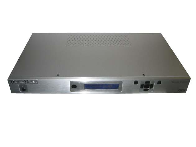
8 N PU 2.0 BASIC OPERATION 2.0 BASIC OPERATION 2.1 Front Panel Overview Status LED IR sensor Front Panel Display (FPD) Adjustment Buttons Menu Up Exit MENU EXIT On/Standby Left Down Right Status LED - This displays the current state of the DreamScaler3: Off: The unit is in standby mode Red: No signal detected Blue: The unit is processing the signal Blinking Blue: There is a problem with HDCP authentification Green: The unit detects an unsupported signal On/Standby - This toggles unit power between On and Standby. IR sensor - This is where all IR commands are received by the DreamScaler3. Do not obstruct this window. Front Panel Display (FPD) - This is where all information from the on screen display (OSD) is duplicated to assist in the setup of your DreamScaler3. When navigating the OSD, the FPD always shows the current selection on the bottom line and the menu/ submenu item on the top line. When you change a value of a setting, the value is on the bottom line and the title of the parameter is on the top line. Navigation Keys - These keys are duplicated on the remote control and function exactly the same. Switching Inputs using the Navigation keys You can switch inputs on the front panel of the DreamScaler3 using the navigation keys (v and ^). To do this, press the Down or Up without pressing the Menu button first. 2.2 Rear Panel Overview SDI Input Analog Video Input Sync 1 Component 1 (YPbPr or RGB) S-Video 1 Composite Video 1 Digital Audio Out (optical) Digital Audio Inputs 1, 2 (optical) Analog Audio Inputs L, R (optical) I Y (G) Pb (B) Pr (R) H V Y (G) Pb (B) Pr (R) 1 2 L R OUTPUT INPUT T O UT P U T DC In I N P U TS OUTPUT 3 INPUT 4 ANALOG AUDIO INPUT HDMI ANALOG VIDEO POWER SYNC COMPONENT S-VIDEO VIDEO DIGITAL AUDIO SERIAL PORT HDMI Output HDMI Inputs 1, 2, 3, 4 Analog Video Output Power Sync 2 Component 2 (YPbPr or RGB) S-Video 2 Composite Video 2 Digital Audio Out (coaxial) Digital Audio Inputs 3, 4 (coaxial) Serial Port Video Inputs The DreamScaler3 has eleven (11) video inputs and an optional SD-SDI input available. The inputs and the formats they support are as follows: Video 1 (NTSC, PAL, PAL-M and SECAM) Video 2 (NTSC, PAL, PAL-M and SECAM) S-Video 1 (NTSC, PAL, PAL-M and SECAM) S-Video 2 (NTSC, PAL, PAL-M and SECAM) Component/RGBS 1 (480i/p@60Hz, 576i/p@50Hz, 720p@50/60Hz, 1080i@50/60Hz) Component/RGBS 2 (480i/p@60Hz, 576i/p@50Hz, 720p@50/60Hz, 1080i@50/60Hz) 8 R DreamScaler3 User Manual
9 2.0 BASIC OPERATION RGBHV/Component (480p, 576p, HDMI 1 (480i/p, 576i/p, 720p@50/60Hz, 1080i@50/60Hz 1080p@24/25/50/60Hz, VGA/SVGA/XGA/ SXGA@60Hz) HDMI 2 (480i/p, 576i/p, 720p@50/60Hz, 1080i@50/60Hz 1080p@24/25/50/60Hz, VGA/SVGA/XGA/ SXGA@60Hz) HDMI 3 (480i/p, 576i/p, 720p@50/60Hz, 1080i@50/60Hz 1080p@24/25/50/60Hz, VGA/SVGA/XGA/ SXGA@60Hz) HDMI 4 (480i/p, 576i/p, 720p@50/60Hz, 1080i@50/60Hz 1080p@24/25/50/60Hz, VGA/SVGA/XGA/ SXGA@60Hz) SD-SDI (480i@60Hz and 576i@50Hz YCbCr 4:2:2) Note: The DreamScaler3 is able to process HDCP protected signals. However, the output signal may be only visible if a valid HDCP supported display is hooked up to the DreamScaler3 s HDMI output connector. The output signal would never be visible through the DreamScaler3 s analog BNC output connectors. Video Outputs The DreamScaler3 has two video outputs, one analog and one digital. The analog output on the DreamScaler3 can output the following signal from any resolutions up to 1920 x 1080: YPbPr (Component) RGBHV RGsB RGBS The HDMI output on the DreamScaler3 can output any resolutions up to 1920 x 60Hz: RGB 4:4:4 (8-bit) YCbCr 4:2:2 (10-bit) YCbCr 4:4:4 (8-bit) To connect the DreamScaler3 to a display that has a DVI input, use either an HDMI-to-DVI cable or an adapter. Audio Inputs There are nine (9) audio inputs on the DreamScaler3: Two (2) Optical Digital inputs Two (2) Coaxial Digital inputs One (1) Analog (L/R) input Four (4) HDMI inputs While the digital and analog audio inputs can be assigned to any one of the video inputs, the HDMI audio inputs are tied directly to the HDMI video signal connected on the same input. The DreamScaler3 accepts digital audio sourced from DVD players, satellite receivers, digital set top boxes, game consoles, or other digital audio devices. These inputs are compatible with most consumer digital audio formats, including CD-Audio (44.1kHz/16 bit LPCM), Dolby Digital, and DTS. The coaxial digital audio inputs are compatible with any format with a sampling frequency between 24kHz and 192kHz, and with a data word structure up to 24 bits in length. The optical digital audio inputs are compatible with any format with a sampling frequency between 24kHz and 96kHz and with a data word structure up to 24 bits in length. The HDMI audio inputs are compatible with HDMI 1.1 audio formats. Audio Outputs There are two digital audio outputs, one coaxial and one optical. Both are active at the same time, with the selected input Digital Audio stream. Power Supply Input The DreamScaler3 comes with a 6V@7A AC-to-DC converter power supply, which accepts VAC at 50/ 60Hz. To attach power to the unit: 1) Attach the removable power cord to the external power supply. 2) Plug the removable power cord into a wall outlet or power conditioner, if applicable. R DreamScaler3 User Manual 9
10 2.0 BASIC OPERATION 3) Plug the small connector attached to the cable that comes out of the power supply into the DC In port on the back of the DreamScaler3. The DreamScaler3 should power on and display DreamVision Powered by ABT on the FPD for a couple of seconds. Use only the power supply that came with your DreamScaler Remote Control Overview The functions of these buttons are detailed in the next paragraph. An asterisk (*) indicates this feature will be implemented in future software. Curtain Info Standby STANDBY INFO CURTAIN POWER Power8 Output Setup Configuration Picture Control Input Adjust OUTPUT SETUP CONFIG PICTURE CONTROL INPUT ADJUST ON/OFF TEST PATTERN DISPLAY VIEWING INPUT PROFILES MODES ASPECT RATIO MEMORIES Test Patterns (Left, On/Off, Right) Display Profiles Viewing Modes * * Input Aspect Ratio Menu MENU EXIT Exit Navigation Keys (Up, Left, Enter, Right, Down) ENTER Aspect Border Zoom BORDER CROP Crop* * Pan ZOOM ASPECT PAN 4:3 16:9 HDMI 1 4:3 16:9 SDI Input Select (HDMI 1, HDMI 2, HDMI 3, HDMI 4, Component 1, Component 2, RGBHV/Component, S-Video 1, S-Video 2, Video 1, Video 2, AUTO) HDMI 2 HDMI 3 HDMI 4 COMP 1 COMP 2 RGBHV S-VIDEO 1 VIDEO 1 S-VIDEO 2 VIDEO 2 AUTO INPUT SELECT Power/Standby Buttons The DreamScaler3 remote has a Power and a Standby button. The Power button always turns the DreamScaler3 on and the Standby button always put the unit into Standby mode. Curtain Button The DreamScaler3 remote has a Curtain button which allows you to close a curtain over the image. This feature is especially useful when an image is paused on a display susceptible to burn-in. Remote Control Battery Installation The remote control for the DreamScaler3 requires two AA batteries. These should be replaced as needed. ABT recommends Alkaline batteries because they last longer without leaking. 10 R DreamScaler3 User Manual
11 2.0 BASIC OPERATION To install the remote control batteries: 1) Locate the battery compartment on the back of the remote control. 2) Remove the cover from the back. To do this, press the tab attached to the cover and pull the cover with the guide on the back of the remote control. 3) Remove the old batteries (if applicable). 4) Insert two new AA batteries in the compartment as shown on the inside of the battery compartment. Make sure the batteries are correctly inserted, observing the proper polarity. 5) After installation, replace the cover and dispose of the old batteries (if applicable). Menu Navigation You can control the DreamScaler3 as follows: From the front panel controls From the remote control From a programmed universal remote control Using the serial connection on the back panel The menu navigation controls on the remote control are duplicated on the front panel of the DreamScaler3. To navigate the menu: 1) Press the Menu button. 2) Use the directional buttons to highlight the parameter you want to change. 3) Press the Enter button to select the parameter and the Left and Right arrow buttons to change the chosen parameter. 4) Press the Exit button to exit out of the menu/osd. Info Screen Button Press the Info button to display a window that shows information about the system including: Input Status Video Source Signal Type Audio Source Aspect Ratio (Frame/Active) Output Status Resolution Frame Rate Line Rate Aspect Ratio (Display/Screen) This screen can be helpful during troubleshooting. R DreamScaler3 User Manual 11
12 3.0 SETUP 3.0 SETUP 3.1 Initial Set-Up Once you have installed the DreamScaler3 into your system, you must properly configure it for the display device being driven. The DreamScaler3 is shipped from the factory with the following preset default settings: Input Select is set to AUTO, to automatically detect an active input in a pre-configured priority. The Digital Video output is selected with RGB 4:4:4 color space The output format is set to SMPTE 274M, 1080p@50Hz or 1080p@60Hz according to the active source refresh rate. Use either the remote control or the front panel controls to perform the initial setup of the DreamScaler3's output. The procedure below uses the front panel buttons to perform initial setup. Accessing the DreamScaler3 s OSD is crucial, not only in allowing you to navigate the menu of the DreamScaler3, but also to let you know that the DreamScaler3 is sending a compatible signal to the display. If the OSD is not visible on the display s screen when you press one of the sub-menu buttons on the remote control, then you must configure the DreamScaler3 with the Output Setup menu to output a signal that the display can accept. Use these steps to allow you to see the OSD. STEP 1 - Power Up 1) Attach the removable power cord to the external power supply. 2) Plug the removable power cord into a wall outlet or power conditioner, if applicable. 3) Plug the small connector attached to the cable that comes out of the power supply into the DreamScaler3. The DreamScaler3 should power on and display DreamVision Powered by ABT on the FPD. STEP 2 - Connect the scaler to your display Displays with a DVI or HDMI Input The default output on the DreamScaler3 is digital RGB 4:4:4 (DVI Standard). If you have changed this setting, follow these instructions to change the settings back. 1) Press the Menu button on the front panel of the DreamScaler3 once. You should see Main Menu /Input Select on the FPD. 2) Press the Up button once. You should see Main Menu / Output Setup on the FPD. 3) Press the Enter button. You should see Output Setup / Analog/Digital on the FPD. 4) Press the Enter button. You should see Analog/Digital / BNC (Analog). 5) Press the Down button to select HDMI (Digital) and press the Enter button. You should see the DreamScaler3 s On Screen Display (OSD) on your screen. Displays with a Component (YPbPr) Input 1) Press the Menu button on the front panel of the DreamScaler3 once. You should see 2) Main Menu / Input Select on the FPD. 3) Press the Up button once. You should see Main Menu / Output Setup on the FPD. 4) Press the Enter button. You should see Output Setup / Analog/Digital on the FPD. 5) Press the Enter button. You should see Analog/Digital / BNC (Analog). If you don t, press the Up button once and the press Enter. You should see Output Setup / Analog/Digital on the FPD. 6) Press the Down button four times. You should see Output Setup / Color Space on the FPD. 7) Press the Enter button once. You should see Color Space / YPbPr on the FPD. If you don t, press the Up button once and press Enter. You should see the DreamScaler3 s on screen Display (OSD) on your screen. The DreamScaler3 cannot output a component signal if the input signal is from a DVI or HDMI source with HDCP. Instead the DreamScaler3 outputs a blue screen. 12 R DreamScaler3 User Manual
13 3.0 SETUP Displays with a VGA HD-15 (Computer) or 5BNC RGBHV input 1) Press the Menu button on the front panel of the DreamScaler3 once. You should see Main Menu / Input Select on the FPD. 2) Press the Up button once. You should see Main Menu / Output Setup on the FPD. 3) Press the Enter button. You should see Output Setup / Analog/Digital on the FPD. 4) Press the Enter button. You should see Analog/Digital / BNC (Analog). If you don t, press the Up button once and then press Enter. You should see Output Setup / Analog/Digital on the FPD. 5) Press the Down button four times. You should see Output Setup / Color Space on the FPD. 6) Press the Enter button once. You should see Color Space / RGB on the FPD. If you don t, press the Up button once and press Enter. You should see the DreamScaler3 s on screen Display (OSD) on your screen. The DreamScaler3 cannot output an RGBHV signal if the input signal is from a DVI or HDMI source with HDCP. Instead the DreamScaler3 outputs a blue screen. STEP 3 - Connecting your Sources to the DreamScaler3 Up to 12 video sources can connected to the DreamScaler3. Use the following suggestions for connections to several popular video sources. VCR/LD Player/DVR VCR/LD Player/DVR 12:00 VIDEO S-Video L AUDIO R IN OUT Composite Video L-Analog Audio R-Analog Audio SDI INPUT OUTPUT INPUT I N PU T O UT P U T Y (G) Pb (B) Pr (R) H V DC In I 1 N PU T S 2 Y (G) Pb (B) Pr (R) OUTPUT INPUT 4 L R ANALOG AUDIO INPUT HDMI ANALOG VIDEO POWER SYNC COMPONENT S-VIDEO VIDEO DIGITAL AUDIO SERIAL PORT Some VCRs and LD players have S-Video outputs. These give an improved picture from these sources. If your LD player or DVR has a digital audio output, DreamVision recommends you use that connection.. R DreamScaler3 User Manual 13
14 3.0 SETUP DVD Player/DVD Recorder DVD Player/ DVD Recorder SDI OUT DVI-D OUT (HDCP) HDMI OUT COMPONENT OUT OPTICAL COAXIAL DVI-D HDMI SDI DVI - HDMI HDMI Component Optical Audio Coaxial Audio HDMI SDI INPUT OUTPUT INPUT I N PU T O UT P U T Y (G) Pb (B) Pr (R) H V DC In I N P U T S 1 2 Y (G) Pb (B) Pr (R) OUTPU T INPUT 4 L R ANALOG AUDIO INPUT HDMI ANALOG VIDEO POWER SYN C COMPONENT S-VIDEO VIDEO DIGITAL AUDIO SERIAL PORT Note: If you have a display with an HDMI/DVI input, DreamVision recommends you use the DVI/HDMI output of your DVD player with the player s output resolution set to the lowest output resolution (preferably 480i). If you have a display with only component or RGBHV inputs, use either an SDI or component video connection. SDI outputs typically need to be added to your DVD player. This gives the additional benefit of skipping an extra digital-to-analog (D-to-A) and analog-to-digital (A-to-D) step for a picture with even more detail then a component connection. With a component connection, set the player s output to 480i, minimizing the amount of processing done in the player. 14 R DreamScaler3 User Manual
15 3.0 SETUP High-Definition Set Top Box or DVR/D-VHS High-Definition Set Top Box or DVR/D-VHS COMPONENT OUT Note: Some set top boxes require you to switch the output resolution. This means that if you are watching an HD channel you must manually switch the output resolution to 720p/1080i/p, or if you are watching an SD channel, you must manually switch the output resolution to 480i or 480p, 480i preferably. If your display only has component or RGBHV inputs, use the component output from your HD source. R DreamScaler3 User Manual 15
16 SDI INPUT OUTPUT INPUT HDMI I T P I ANALOG VIDEO DC In DC In POWER I I 1 2 SYNC 1 2 COMPONENT 1 2 S-VIDEO 1 2 VIDEO OUTPUT OUTPU T 1 INPUT 3 DIGITAL AUDIO 2 4 INPUT L R ANALOG AUDIO INPUT SERIAL PORT 3.0 SETUP Game Console Game Console Optical Audio Proprietary HDTV AV Pack Component SDI INPUT OUTPUT INPUT N PU T O UT P U T Y (G) Pb (B) Pr (R) H V N PU T S 1 2 Y (G) Pb (B) Pr (R) L R ANALOG AUDIO INPUT HDMI ANALOG VIDEO POWER SYN C COMPONENT S-VIDEO VIDEO DIGITAL AUDIO SERIAL PORT Set the game console to output the highest resolution available to get the best results. Personal Computer Personal Computer DVI-D DVI-D DVI- HDMI Optical Audio Coaxial Audio RGBHV N PU O UT U T Y (G) Pb (B) Pr (R) H V N P U T S Y (G) Pb (B) Pr (R) Only VGA (640x480), SVGA (800x600), XGA (1024x768), and SXGA (1280x1024) resolutions are supported at 60 Hz. 16 R DreamScaler3 User Manual
17 3.0 SETUP 3.2 Audio Operation The DreamScaler3 features an audio delay function to exactly match the video delay incurred by the video processing. It accepts four discrete digital audio inputs: two coaxial (Audio 1, 2) and two optical (Audio 3 and 4), one analog audio input and four HDMI audio inputs. The locations of the audio inputs are shown on the back panel diagrams earlier in this product guide. The factory default audio assignment is as follows: Audio 1 (optical): none Audio 2 (optical): none Audio 3 (coaxial): none Audio 4 (coaxial): none Stereo (analog): none Note: The HDMI audio inputs can only be assigned to the same HDMI video input although any of the other audio inputs can be assigned to any of the HDMI video inputs.you can assign a Digital Audio input to each Video input in the following manner: You can assign an audio input to each Video input in the following manner: 1) Select a video input on the remote control. 2) Select Audio 1, 2, 3, 4, Stereo, HDMI or Off from the Input Adjust/Audio Input menu. If an analog video input is selected, the HDMI option will not be available. R DreamScaler3 User Manual 17
18 4.0 MENU OPTIONS 4.0 MENU OPTIONS 4.1 Input Select There are twelve available inputs on the DreamScaler3: VIDEO 1 Video 1 (Composite) VIDEO 2 Video 2 (Composite) S-VIDEO 1 S-Video 1 S-VIDEO 2 S-Video 2 COMPONENT 1 Component/RGBs 1 COMPONENT 2 Component/RGBs 2 RGBHV RGBHV/Component HDMI 1 HDMI 1 HDMI 2 HDMI 2 HDMI 3 HDMI 3 HDMI 4 HDMI 4 AUTO Automatic active input detection and selection SDI SD-SDI (SDI Video Input Module required) These inputs can be accessed in five different ways: Using the front panel using the Left and Right buttons Using the remote control with the direct access buttons Using a universal remote programmed with the discrete codes Using the OSD from the front panel or from the remote to access the Input Select menu Using RS232 Serial Automation Protocol described in the appendix. 4.2 Input Aspect Ratio Control The Input Aspect Ratio control selects the aspect ratio for the current input signal. The DreamScaler3 automatically converts from the selected input aspect ratio to the selected output aspect ratio. Push the Aspect button once to show the current input aspect ratio control function. To cycle through the available functions, push the Aspect button repeatedly. For the Input AR function, push the Up or Down button once to show the current setting. Push either of these buttons again to cycle through the available aspect ratios. Push the Exit button to exit the menu and go back to the Input Aspect Ratio selection. For the Zoom, Pan and Borders functions, push the Up or Down button to select the two control settings available: horizontal and vertical. Push the Enter button to adjust each setting. Push Up and Down to increase or decrease the setting. Push Exit again to exit this mode. Note: The Zoom and Pan functions are applied to the input signal, not the output. This is an important consideration, especially for the Pan function. For example: If you do not zoom a full frame image more than 100%, there is nothing to pan. However, if part of the image is not on the screen, then the Pan function will work. The DreamScaler3 s menu is exit automatically after 30 seconds of no user interaction. Video input signals are usually classified in the following two ways: Frame Aspect Ratio Active Input Aspect Ratio 18 R DreamScaler3 User Manual
19 4.0 MENU OPTIONS Frame Aspect Ratio Frame Aspect Ratio (FAR) consists of two possible ratios: 4:3 or 16:9. DVD discs encoded in a 16:9 frame are sometimes referred to as anamorphic or enhanced for widescreen TV s. For example, a non-anamorphic widescreen DVD has a FAR of 4:3. Active Aspect Ratio Active Aspect Ratio (AAR) is the aspect ratio of the image or content (movie). This content is typically stated on the back cover of DVD discs. Some common active aspect ratios are as follows: 1.33:1 (4:3) 1.55:1 1.66:1 1.78:1 (16:9) 1.85:1 2.35:1 (Cinemascope) To use aspect ratio s in addition to these, the DreamScaler3 provides the option to choose a custom aspect ratio called User with a range of 1.01:1-3.00:1. DreamScaler3 Image Mapping The situation when the Frame Aspect Ratio (FAR) is the same as the Active Aspect Ratio (AAR) is sometimes called Full Frame. This situation is illustrated below. The DreamScaler3 maps the AAR to the Output Aspect Ratio (OAR) in the following three ways: When the AAR is greater than OAR, the DreamScaler3 puts up Borders at the top and bottom as shown below: Active Input Area Borders When the AAR is less than the OAR, the DreamScaler3 puts up Borders on the left and right as shown below: Active Input Area Borders When the AAR is equal to the OAR (Output Aspect Ratio), the DreamScaler3 supplies no border as shown R DreamScaler3 User Manual 19
20 4.0 MENU OPTIONS below. Panorama The Panorama feature is a non-linear stretch that can be applied only to a 4:3 video source. The panorama stretches the picture with minimal perceptual distortion in the center of the screen. This mode can be turned On or Off. Additionally this feature can be accessed in the IAR presets and it is titled 4:3 Stretch. Zoom The Zoom function zooms in on or magnifies the image on your display. The minimum zoom is 100%, (no zooming); the maximum zoom is 150% (zoom magnification factor of 1.5X). Horizontal Zoom Control: Push the Enter button to show the current Zoom setting. Push the Up and Down button to increase or decrease the zooming factor. Vertical Zoom Control: Push the Enter button to show the current Zoom setting. Push the Up and Down button to increase or decrease the zooming factor. Pan The Pan function allows the image to be shifted up, down, left and right. Note that the Pan function can only be used after the image has been zoomed to any value greater than 100%. Horizontal Pan Control: Push the Enter button to show the current Pan setting. Push the Up button to pan to the right. Push the Down button to pan to the left. Vertical Pan Control: Push the Enter button to show the current Pan setting. Push the Up button to pan up. Push the Down button to pan the image down. Borders The Borders function allows you to add horizontal and/or vertical borders around the image. These borders obscure part of the input image. Certain input-to-output aspect ratios already result in left/right or top/bottom border being added. This control allows the system-generated borders to be extended, or for borders to be added when none exist. As the borders are adjusted (see below) thedreamscaler3 temporarily increases the gray level of the borders so that they are visible during the adjustment process. The level will return to normal after the adjustment has ceased. Horizontal Border Control: Push the Up button to move the left and right borders towards the middle of the image, increasing the border width and cutting off the sides of the input image. Push the Down button to move the left and right borders away from the image and decreases their width. If there are system-generated left/right borders already present (for example, when the input aspect ratio is 4:3 and the output aspect ratio is 16:9), the border width cannot be decreased beyond the base width created by the aspect ratio conversion. Vertical Border Control: Push the Up button to move the top and bottom borders towards the middle of the image, increasing the border height and cutting off the sides of the input image. Push the Down button to move the top and bottom borders away from the image and decrease their height. If there are system-generated top/ bottom borders already present (for example, when the input aspect ratio is 16:9 and the output aspect ratio is 4:3), the border height cannot be decreased beyond the base height created by the aspect ratio conversion. Borders are automatically added by the system when the Active Input Aspect Ratio is not the same as the Output Aspect Ratio as explained earlier in this guide. However you can add more borders using the Borders menu. Presets You can specify the Input Aspect Ratio by using the Presets or Manually. 20 R DreamScaler3 User Manual
21 4.0 MENU OPTIONS Using Presets You can use Presets with either the OSD or the Remote Control Input Aspect Ratio button. Refer to the Preset submenu in the Input AR menu for doing this with the OSD. The remote control operation is described below. 4:3 Selects 4:3 Full Frame without OSD. 16:9 Selects 16:9 Full Frame without OSD. Pushing the Input Aspect Ratio button repeatedly selects Preset 1 through Preset 10 and User in sequence without using the On-Screen Display (OSD). The ten user-defined preset value selections (Preset 1-10) are stored in non-volatile memory and always available. Each of these presets consists of the following: Frame Aspect Ratio Active Input Aspect Ratio Zoom parameter Pan parameter Borders The User preset selection is also stored in non-volatile memory. However the User selection is always updated after you modify any pre-defined aspect ratio setting. In order to permanently keep a custom aspect ratio setting, you must save it to one of the four preset selections. Setting the Input Aspect Ratio Manually You can set the following parameters manually: Frame Aspect Ratio Active Input Aspect Ratio Zoom factor Pan parameter Borders (horizontal and vertical) Typically you only need to select the Frame Aspect Ratio and Active Input Aspect Ratio to get an acceptable picture. The Active Input Aspect Ratio menu item lists the most common movie aspect ratios (1.33:1, 1.85:1 and 2.35:1). You can also customize the Input Aspect Ratio using the Up and Down buttons. Save User-defined presets as follows: Customize the aspect ratio manually (refer to Setting the Input Aspect Ratio Manually above). Select one of the presets from the Save User To menu. Confirm the action by selecting Yes. Be careful, because saving to a preset deletes the previous preset. If you have not customized the aspect ratio, and the current aspect ratio settings are the same as a system defined preset. In this case, the system will not allow you to save the preset setting. Front Panel and On-Screen Displays for IAR The On-Screen Display (OSD) and the Front Panel Display (FPD) allow you to set the Input Aspect Ratio. 4.3 Input Adjust Control Push the Input Adjust button once to show the current input adjustment function. You can cycle through the available functions by pushing this button repeatedly. The available input adjust functions are as follows: Overscan Deinterlacing Pass Through Line Offset Color Space Input Level R DreamScaler3 User Manual 21
22 4.0 MENU OPTIONS VCR mode Film mode HDCP Mode Auto Priority Audio Input AV Lip Sync Deinterlacing You can choose between seven different deinterlacing methods that better suits your need: Auto: This setting is to be used with when the content may be a mix of film and video based content. Film Bias Mode: This mode is intended for use on content that is known to be film-based Video Mode: This mode is intended for use on content that is known to be video-based. 2:2 Even: This mode should be used when the user knows that the source is high-quality 2:2 pulldown (i.e. film-based content played back in a country with a 50Hz video standard) and wants to avoid any loss of cadence lock while watching that source. This mode weaves two adjacent fields together starting with an even field and combining it with the following odd field. This will provide a higher quality overall signal than the Auto or Film Mode settings, providing that the source really is 2:2 pulldown and does not have bad edits. Only one of the 2:2 Deinterlacing settings is correct for any given source and the correct mode can be chosen by simply trying both of them and selecting the one which does not result in combing artifacts. 2:2 Odd: This mode is very similar to 2:2 Even except that this weaves two adjacent fields together starting with an odd field and combining it with the following even field. Game Mode 1: This mode gives you minimal latency with edge-adaptive processing. The total amount of delay with sourcelocked output mode set on the DreamScaler3 is about half a frame of delay. Unlocked frame rates will increase this delay. Game Mode 2: This mode gives you minimal latency with both motion and edge-adaptive processing. The total amount of delay with source-locked output mode set on the DreamScaler3 is about one and a half frames of delay. Unlocked frame rates will increase this delay. PReP PReP stands for Progressive ReProcessing. This is the first video processing method that significantly improves progressive video signals and removes artifacts caused by inferior interlaced-to-progressive conversion. Video signals that originate in an interlaced format are often degraded by artifacts incurred when the signal is converted from interlaced to progressive formats by general purpose chips in DVD players, AV receivers, and set-top boxes. Poor interlaced-to-progressive conversion is especially problematic with large-screen HDTVs, as upscaling to higher resolutions often amplifies artifacts created in the conversion process, making them more noticeable. Turning on PReP video processing will improve images on high-resolution displays and give access to the Precision Deinterlacing menu. PReP should be activated only with progressive video input known to be originally interlaced. Overscan The Overscan function scales the input image proportionally in both vertical and horizontal dimensions by the userspecified overscan factor. The purpose of Overscan is to remove unwanted image portions around the perimeter of the image. The default overscan value is 0, which means 100% of the input image is shown. The maximum overscan value is 20 which means the input image is scaled up by 120%. To adjust the overscan level: 1) Push the Up or Down button. The current level is shown. 2) Push the Up or Down button to decrease or increase the amount of overscan. The Overscan value is applied to all input aspect ratios and is independent of the Zoom value. Line Offset The image can be adjusted vertically when an SDI or HDMI (480i/576i) input when you use the Line Offset function. This function can be set independently for both 480i and 576i input formats. 22 R DreamScaler3 User Manual
23 4.0 MENU OPTIONS Color Space The color space setting allows the user to specify what the input signal is on the RGBHV/Component and HDMI inputs. The YPbPr setting only applies to the RGBHV/Component input. The YCbCr 4:2:2 and YCbCr 4:4:4 and Auto settings only apply to the HDMI inputs. The options are: RGB YPbPr YCbCr 4:2:2 color space YCbCr 4:4:4 color space Auto Input Level The input level setting allows the user to specify the levels of the input signal, either Video (16-235) or PC (0-255) Video PC VCR Mode VCR Mode decouples the output timing completely from the input timing to ensure a stable output from the DreamScaler3 for VCR playback especially during trick-play modes (play forward, play reverse, still/pause). On Output timing is decoupled from the input timing regardless of Frame Rate settings. Off Output timing is dependent on Frame Rate settings. Auto - Turns on VCR Mode if a VCR source is detected. HDMI Config The HDMI Config menu gives access to three parameters HDCP mode Off: HDCP is disabled at the DreamScaler3 s HDMI input. some sources turn off HDCP in this case and the DreamScaler3 drives a non-hdcp DVI display or an analog display. On: The DreamScaler3 continuously looks for a HDCP source on its HDMI input. Auto Aspect Ratio Off: The Aspect Ratio is determined by user. On: The DreamScaler3 reads the video aspect ratio contained into the Info Frame and applies it if available. Auto Color Space Off: The Color space is determined by user. On: The DreamScaler3 applies the Color Space specified into the Info Frame if available. Auto Input Priority Selection The Auto Input Priority Selection function assigns different priorities to the video input s automatic active video selection mode (AUTO in Input Select menu). First select the video input, then change the priority of that input. 1) Press the Down button. The first video input Video 1 is shown. 2) Press the Enter button to view the current priority of the selected input. 3) Press the Up or Down button to change the priority of the selected input. 4) Press the Exit button again to complete the priority assignment. 5) Repeat Steps 1 through 4 to select the next video input and adjust the priority setting. Audio Input The Audio Input function assigns an audio input to the currently selected video input. Four digital audio inputs and a single analog audio input are available. To assign the audio input to another video input, push the Down button. The front panel display (FPD) shows the current setting. For more info about how to assign an audio input to a video input, refer to Audio Input Operation. R DreamScaler3 User Manual 23
24 4.0 MENU OPTIONS AV Lip Sync The DreamScaler3 automatically delays the input audio to match the video processing delay. You can choose to increase or decrease the audio delay by changing this setting. Push the Up or Down button to display the current additional bias delay setting (default 0). Use the Up or Down button to increase or decrease the delay in milliseconds. 4.4 Picture Controls Brightness This control adjusts the brightness (black level) of the overall image output from the DreamScaler3. If you turn it up too high, it may make black look gray. In general, you should adjust this up until you see the black areas of your display turn gray and then back it down just below that point. Default setting is 0 (midrange). Contrast Contrast adjusts the ratio between white and black signal levels and is effective as a gain control. The difference between this and the Brightness control is that this adjusts the difference between the brightest and darkest part of the image. Note that all displays have a maximum white level. Going beyond this level only clips the upper gray levels and you will lose color resolution at the brighter levels. Adjust this control up until you see the brighter levels of the image begin to wash out. At this point, back it down just below that point. The default setting is 0 (midrange). Saturation The DreamScaler3 allows you to control the saturation of the image independent of the display. Saturation is the same as the Color control on most TVs and controls the richness of the color in the image. The default setting is 0 (midrange). Hue Note: The total audio delay cannot be less than zero, that is, the DreamScaler3 cannot have negative audio delay. If you choose to decrease the automatic delay setting by a certain amount, this value could be changed by the DreamScaler3 in situations where the DreamScaler3 s calculated delay plus the specified additional delay results in a value less than zero. As with Saturation, hue can also be controlled independent of the display. Hue is the same as the Tint control found on most TVs and controls how colors are displayed in the image. The Hue control is not available for Component or PAL/SECAM inputs. The default setting is 0 (midrange). Sharpness The Sharpness setting adjusts the sharpness of the selected input signal. The default setting is 0. Y/C Delay Sometimes there is a lag between the Luminance (Y) and the Chrominance (Pb/Pr or Cb/Cr) of the video signal. This causes a color smearing because the color component of the image is not lining up properly to the black and white luminance component of the image. The DreamScaler3 can compensate for these errors in the source signal by shifting the phase of the Y with respect to the C, forward or backward to align them properly. Use the Down and Up buttons to adjust the phase and observe the effects on your display to obtain the optimal setting. The default is 0. Chroma Filter (Auto CUE-C) This feature removes chroma upsampling errors (CUE) found in video sources which have been MPEG encoded and then improperly decoded. Off - No chroma filtering. Use this setting if the source does not have a CUE problem. On - Chroma filtering is always on. Use this setting if the source is known to have a CUE problem. Auto - Automatic chroma error detection and correction. Use this setting when you don t know if a source has a CUE problem. Also use this setting for all digital sources which use MPEG2 decoders (DVD players, digital satellite receivers, and so on.) as it will also detect and correct chroma errors created by all sources of this type 24 R DreamScaler3 User Manual
25 4.0 MENU OPTIONS when the source is encoded as interlaced (also sometimes called Interlaced Chroma Problem, or ICP). 4.5 Configuration Test Patterns The DreamScaler3 has 35 internal test patterns to assist in the setup of your individual sources and your display. To learn more about how to use the internal test patterns, refer to the section Setting up an DreamScaler3 Using the Internal Test Patterns and Avia: Guide to Home Theater Calibration DVD. To turn the test patterns on and off, use the Test Pattern On/Off button. To navigate backwards and forwards through the available test patterns use the < and > buttons, respectively. Auto Standby The default setting is Off, which means DreamScaler3 is always in Active mode, regardless of the activity state of the selected input. If Auto Standby is On, the DreamScaler3 goes into Standby mode 30 seconds after the selected input becomes inactive. To see the current setting, press Up or Down. Then press the same button again to change the setting. LED Brightness This selection allows the user to configure the behavior of the Front Panel LED brightness. The Active parameter adjusts the brightness of the Front Panel LED when the menu is being navigated. The Reduced parameter adjusts the brightness of the Front Panel LED during normal usage, when the menu is not being navigated. User Mode You have limited access to the output timing controls in Normal mode. In Advanced user mode, you have access to the complete set of output timing controls. Push the Down button to see the current setting and the FPD displays either Normal or Advanced user level. Push the Down button again to select the alternate mode. Serial Port Rate The serial port is used by the automation system controllers to control the DreamScaler3. The serial port baud rate defaults to bps, but can be changed using the Up or Down button. The supported baud rates are: 4800 bps (4.8K) 9600 bps (9.6K) bps (14.4K) bps (19.2K) bps (38.4K) bps (57.6K) Factory Default The Factory Default option allows you to reset system settings to the factory default. 1) Press either the Up or Down button. The FPD displays No. 2) Press the same button to switch to Yes. 3) Confirm this selection by pressing the Enter button. The default factory settings are as follows: Input Selection: Auto Input Aspect Ratio: 4:3 for 480i/p and 576i/p inputs. 16:9 for 720p and 1080i/p Picture Controls: midrange (0) Chroma Filter (CUEC): Auto Output Aspect Ratio: 16:9 Output Resolution: 1080p Output Color Space: RGB 4:4:4 Output Type: Digital Auto Standby: Off Frame Rate: the output frame rate is automatically scaled to the input source frame rate. User Mode: Normal R DreamScaler3 User Manual 25
26 4.0 MENU OPTIONS Video Input Priority Settings: 1 HDMI 1 2 HDMI 2 3 HDMI 3 4 HDMI 4 5 Component 1 6 Component 2 7 S-Video 1 8 S-Video 2 9 Video 1 10 Video 2 11 SDI 12 RGBHV/Component Digital Audio Input Assignment: each video input can be assigned to an audio input, this setting is set to off by default. Software Update To install the latest software for your DreamScaler3, please follow the procedure described below. 1) Set the communication speed to bps in the serial baud rate menu. 2) Connect the DreamScaler3 to your computer with the RS-232 cable. 3) Change the software update value to Yes to begin the update process. The upgrade procedure is fully detailed in the Software Update Procedure. Information This setting shows information about the system including: Input Status Video Source Signal Type Audio Source Aspect Ratio (Frame/Active) Output Status Resolution, Color space Frame Rate Line Rate Aspect Ratio (Display/Screen) This screen can be helpful during troubleshooting. 4.6 Output Setup Analog/Digital (A/D) Push the Down button to show the current output type. Push the Down button again to select the next item on the list shown below. You can also use the Up button to cycle through the output types. Analog Output (BNC-style connectors) Digital Output (HDMI connector) 26 R DreamScaler3 User Manual
27 4.0 MENU OPTIONS Output Format Push the Down button to show the current output format. Push the Down button again to show the next item on the list below. You cannot select the format until you press the Exit button. Press the Enter button again to select the output timing controls, explained in the Output Timing section. Horizontal Resolution Vertical Resolution Output Aspect Ratio Control Scan Type There are four controls for Output Aspect Ratio (OAR): Display Aspect Ratio Screen Aspect Ratio Image Shift Underscan Sync Signal Line Sync Signal Type Colorspace P Y Bi-level YPbPr P Y Tri-level YPbPr P Y Bi-level YPbPr (720p-50) P Y Tri-levle YPbPr (720p-60) P Y Tri-level YPbPr (1080i-50) I Y Tri-level YPbPr (1080i-60) I Y Tri-level YPbPr (1080p-50) P Y Tri-level YPbPr (1080p-60) P Y Tri-level YPbPr P Y Tri-level YPbPr P H-V- - RGB P H+V+ - RGB P H-V- - RGB P H-V- - RGB P H-V- - RGB P H-V- - RGB P H-V- - RGB P H-V- - RGB P H-V- - RGB P H-V- - RGB P H-V- - RGB P H-V- - RGB P H-V- - RGB P H-V- - RGB P H-V- - RGB P H-V- - RGB P H-V- - RGB P H-V- - RGB Table 1: Preset Formats and Characteristics for Analog Video Output R DreamScaler3 User Manual 27
28 4.0 MENU OPTIONS The Display Aspect Ratio is the full aspect ratio of the display, normally specified in the display manual. Common display aspect ratios are 4:3 and 16:9. Less common ones are 5:4, 2.35:1 and others. The example below shows a 4:3 projection with a 16:9 screen. 3 9 Active Output Area Mask 16 4 The region outside the Active Output area (called the mask) is inactive, and only important for creating video timing signals for the display. Input video data is never mapped to this region. When the Display Aspect Ratio is not the same as Active Output Aspect Ratio, the mask is set to blanking levels and always centers the position of the active area over the display area. Image shift allows you to adjust the location of the image on your screen both horizontally and vertically when the Screen aspect ratio is not equal to the Display aspect ratio. The example below shows 16:9 projector (1.78:1) and a 2.35:1 screen, you can shift the image to match the exact location of your screen. In this situation, the image is shifted down putting all of the mask at the top of the projected image. Screen Aspect Ratio (2.35:1) Mask Screen Aspect Ratio (2.35:1) Underscan represents the visible display area, a sub-set of the Active Output Area. Underscan is like a negative zoom which preserves the aspect ratio of the active area. The default for this setting is 0. As you increase underscan, the smaller portion of the active display area appears while preserving the aspect ratio of the active display area. Image Active Output Sync Type The Sync Type option sets the synchronization signal type of the output format. Press the Up or Down button to show the current sync type. Press the same button again to move to the next synctype. Currently, the DreamScaler3 supports seven sync types: Bi-level bi-level sync on green/luma Tri-level tri-level sync on green/luma CSync Composite Sync (on the H sync BNC connector) H+V+ Positive Hsync and Positive Vsync H+V- Positive Hsync and Negative Vsync H-V+ Negative Hsync and Positive Vsync H-V- Negative Hsync and Negative Vsync 28 R DreamScaler3 User Manual
29 4.0 MENU OPTIONS Color Space The color space parameter sets the color space of the output format. Press the Up or Down button to show the current color space. Press the same button again to select the alternate color space. Two analog color space options are supported: YPbPr (default) and RGB. Two digital color space options are supported: RGB (default) and YCbCr (both 4:2:2 and 4:4:4). Output Level The output level setting allows the user to specify the levels of the output signal, either Video (16-235) or PC (0-255) Video PC Framerate Conversion This parameter enables framerate conversion. There are four sets of controls: 24Hz, 25Hz, 50Hz and 60Hz framerates. Each framerate menu determines the conversion applyed to the active video source. You can choose between: Locked mode (1:1): This means that the iscan s output frame rate tracks the input rate - i.e., the output rate is locked to the input rate. In the 1:1 mode. There is always exactly one output frame for every input frame/field. This mode has the advantage that there are never any dropped or repeated frames (unless the source itself does this). One disadvantage of this mode is that when the video source is changed, the DreamScaler3 has to re-lock to the new input signal timing. This can causes a disruption in the DreamScaler3 output signal and your display system may loose the video signal and temporarily. Unlocked mode: This means that the DreamScaler3 frame rate is independent of the input rate. Regardless of any variations in the input, the output frame rate will be fixed at the specified value. This mode results in the most stable output signal as it s independent of any changes in the input signal. Unlike the locked mode, the DreamScaler3 output signal will not be disrupted when the input source is changed. However, it s guaranteed to cause dropped or repeated frames as the input and output frame rates are not the same. Note that regardless of what number the unlocked output frame rate is set to, it will never be identical to the input rate in this mode as the output signal timing is independent of the input timing. These dropped/repeated frames can result in visible irregularities in smooth motion, sometimes called motion judder or stutter. Locked mode (2:2 or 3:3): For standard definition interlaced sources the DreamScaler3 can detect 2:2 and 3:2 pulldown cadences and convert these to either a 2:2 or 3:3 frame repetition rate. The main advantage of this is for 60 Hz sources using 3:2 pulldown, as the irregular 3:2 pattern can be converted to 2:2 at 48 Hz or 3:3 at 72 Hz. In these modes, each original film frame is repeated exactly 2 or 3 times, respectively, and motion is therefore smoother. Note that these modes are only useful when the video source is film-based - i.e., 3:2 pulldown for 24 Hz film on 60 Hz sources, and 2:2 pulldown for 25 Hz film on 50 Hz sources. If the source is not film-based, then the end result is a lot like unlocked mode without that mode s stability advantages. Border Level The border level setting is global, that is, there is only one border level setting for the system. To adjust the border level, push the Up or Down button. The current level is shown. The default value is 0. Push the Up or Down button to decrease or increase the border level. Gamma Correction The default gamma curve on the DreamScaler3 output is linear (1.0 by default). This should be left set to linear unless you choose the correct output gamma curve for the connected display. The range is 0.5 to 2.5 for Red, Green and Blue color channels. HDCP Mode There are two HDCP modes: Off: HDCP is disabled at the DreamScaler3 s HDMI output. On: The DreamScaler3 continuously looks for a HDCP display device on its HDMI output. Display Profiles A display profile is a group of display parameters you can save and easily recall in the future. A display profile consists of a set of display parameter selected from the Output Setup menu. This includes the following: Output Type (Analog or Digital) Format (Resolution and all video output timing information) R DreamScaler3 User Manual 29
30 4.0 MENU OPTIONS Output Aspect Ratio Sync Type Color Space (YPbPr/YCbCr or RGB) Output Level (Video or PC) Frame Rate Conversion information Border Level Gamma Correction HDCP Mode You can save up to ten display profiles (Profile 1 through 10). A current custom display profile (called User) is also stored in non-volatile memory. However it will be overridden when you make any modifications to the display profile. You should always save the current display profile to Profile 1 - Profile 10 to prevent the custom profile from being lost. The Display Profile feature is only enabled when you set the User Mode to Advanced, just like the full control of output timing parameters in the Format menu. The factory default values for the ten display profiles and User are as follows: Output Type Digital Format 1080p Output Aspect Ratio 16:9 Active Output AR 16:9 Sync Type H-/V- Color Space RGB 4:4:4 Output Level Video Frame Rate Locked mode (1:1). Border Level 0 HDCP Mode On Selecting and Saving a Display Profile Use the following procedure to select and save a display profile: 1) Set up the profile by making changes to the output setup menu items. If you make custom settings (such as output timing parameters), they are saved to User. 2) Save the settings to a profile by selecting Profile 1 through 10 in the Save menu and pressing Enter. 3) Once the Profile is saved, the Save menu is grayed out until you make changes to the profile again. Auto Linking of Input and Display Profiles The Auto feature links a specific input to a display profile. To enable this feature, use Output Setup [Display Profile] Auto. When you select an input/format, the display profile used (Profile 1 through 10 or User) is saved in the saved input settings. When you turn Auto On, the system uses a display profile based on the selected input. For example, suppose you choose Display Profile 1 using Video 1 input and Display Profile 2 using S-Video 1 input. With Auto set to On, when Video 1 is the active input, the system automatically uses Display Profile 1. When S-Video 1 is the active input, Display Profile 2 is used. When Auto is Off, the selected display profile is used independently of the active input. 30 R DreamScaler3 User Manual
31 5.0 APPENDIX 5.0 APPENDIX 5.1 Non-Volatile Memory Settings The DreamScaler3 stores a variety of user settings in non-volatile memory. Non-volatile memory retains its contents when power is lost. There is one group of system settings and one group of user settings. System Settings Setting Display Profile Auto Display Profile Active Input Auto StandBy Video Priority User Mode Border Level HDMI Input Power LED Test Pattern Generator SDI Line Offset Serial Port Bit Rate HDCP Mode Description One of ten display profiles or User If enabled, selects a display profile based on input selection One of many DreamScaler3 inputs or auto Active input Off or On Priority list of inputs when Auto Active Input is on Normal or Advanced Blank to quarter gray Input mode is automatic On, Off or Auto Current selected test pattern One for 50Hz input and one for 60Hz input Select an available baud rates Auto or On Table 2: System Settings Input / Format Settings The DreamScaler3 supports an independent set of saved settings based on input and format. Settings Input Format 1 Composite 1 NTSC 2 Composite 2 PAL/SECAM 3 S-Video 1 NTSC 4 S-Video 2 PAL/SECAM 5 Component / RGBS 1 480i (NTSC) 6 Component / RGBS 1 576i (PAL/SECAM) 7 Component / RGBS 1 480p (NTSC) 8 Component / RGBS 1 576p (PAL/SECAM) 9 Component / RGBS 1 720p (ATSC) 10 Component / RGBS i (ATSC) 11 Component / RGBS 2 480i (NTSC) 12 Component / RGBS 2 576i (PAL/SECAM) 13 Component / RGBS 2 480p (NTSC) 14 Component / RGBS 2 576p (PAL/SECAM) 15 Component / RGBS 2 720p (ATSC) 16 Component / RGBS i (ATSC) 17 RGBHV/Component 480p (NTSC) 18 RGBHV/Component 576p (PAL/SECAM) 19 RGBHV/Component 720p (ATSC) 20 RGBHV/Component 1080i (ATSC) 21 RGBHV/Component VGA 22 RGBHV/Component SVGA 23 RGBHV/Component XGA Table 3: Input / Format Settings R DreamScaler3 User Manual 31
32 5.0 APPENDIX 24 RGBHV/Component SXGA 25 SDI 480i (NTSC) 26 SDI 576i (PAL/SECAM 27 HDMI 1 480i (NTSC) 28 HDMI 1 576i (PAL/SECAM) 29 HDMI 1 480p (NTSC) 30 HDMI 1 576p (PAL/SECAM) 31 HDMI 1 720p (ATSC) 32 HDMI i (ATSC) 33 HDMI 1 VGA 34 HDMI 1 SVGA 35 HDMI 1 XGA 36 HDMI 1 SXGA 37 HDMI 2 480i (NTSC) 38 HDMI 2 576i (PAL/SECAM) 39 HDMI 2 480p (NTSC) 40 HDMI 2 576p (PAL/SECAM) 41 HDMI 2 720p (ATSC) 42 HDMI i (ATSC) 43 HDMI 2 VGA 44 HDMI 2 SVGA 45 HDMI 2 XGA 46 HDMI 2 SXGA 47 HDMI 3 480i (NTSC) 48 HDMI 3 576i (PAL/SECAM) 49 HDMI 3 480p (NTSC) 50 HDMI 3 576p (PAL/SECAM) 51 HDMI 3 720p (ATSC) 52 HDMI i (ATSC) 53 HDMI 3 VGA 54 HDMI 3 SVGA 55 HDMI 3 XGA 56 HDMI 3 SXGA 57 HDMI 4 480i (NTSC) 58 HDMI 4 576i (PAL/SECAM) 59 HDMI 4 480p (NTSC) 60 HDMI 4 576p (PAL/SECAM) 61 HDMI 4 720p (ATSC) 62 HDMI i (ATSC) 63 HDMI 4 VGA 64 HDMI 4 SVGA 65 HDMI 4 XGA 66 HDMI 4 SXGA Table 3: Input / Format Settings Note: There is a separate set of settings not just for each input but for each format as well. This provides a lot of flexibility but is complex. For example, you can make settings for an input with an NTSC source, but when the source is changed to PAL, you must specify new settings. 32 R DreamScaler3 User Manual
33 5.0 APPENDIX Format settings Each Input / Format contains the settings below: Setting Description Picture Control Brightness Contrast Saturation Hue Sharpness Chroma Error Correction Y/C Delay Display Profile Profile 1-10 or User Audio Select Audio 1-4 Audio Delay Overscan VCR Mode Film Mode Input A/R Preset Preset 1-10 or User Preset User Preset Frame AR Active Input AR Pre-defined or User AR User AR Hor. Zoom Vert. Zoom Hor. Pan Vert. Pan Hor. Borders Vert. Borders Table 4: Input / Format settings There is only one set of presets (Preset 1 through Preset 10) for the whole system. However the User Preset is per input and per format. 5.2 Setting up an DreamScaler3 Using the Internal Test Patterns The DreamScaler3 has 35 built-in test patterns to assist in the setup of your display and your individual sources. DreamVision recommends that you use the Avia Guide to Home Theater DVD to assist in this setup. Determining the Correct Output Resolution for Your Display Determine the optimum output resolution to set your DreamScaler3 to get the best picture from your display. To do this correctly, you must know what the native resolution or maximum resolution of your display. Native resolution refers to the actual pixel count of a fixed pixel display. Fixed pixel display technologies include plasma, LCD, DLP and LCoS. CRT-based technologies use scan lines so they do not have a native resolution but they do have a maximum resolution. Keep in mind that some displays do not accept their native resolution. The following is an example of specifications from an LCD TV: Diagonal Screen Size (inches) 32 Display Capability 480p/720p/1080i/p Aspect Ratio 16:9 (Widescreen) Resolution (Number of Pixels) 1280 x 768 (1,049,088 pixels) The native resolution of this display is 1280x768, which a DreamScaler3 can output, but this display is only capable of accepting 480p, 720p, or 1080i signals. For this display, the best output resolution to choose on the DreamScaler3 is 720p, since it is the closest to the native resolution of this display. An example of the specifications from a CRT-based rear projection display is shown below: R DreamScaler3 User Manual 33
34 5.0 APPENDIX Diagonal Screen Size (inches): 53 Aspect Ratio: 16:9 (Widescreen) CRT Type: 7 Diagonal HDTV Compatibility: 540p/1080i This display only displays two resolutions, both of which the DreamScaler3 can output. To find out which one looks best on your display use familiar material, like a favorite DVD, to compare to find out which resolution is more to your liking on your display. Below are several different popular display technologies and their most likely native resolutions. Plasma x480, 1024x768, 1024x1024, 1024x x768, 1360x768, 1366x768, 1920x1080 DLP Rear Projection 1280x720 (720p), 1920x1080 (1080p) Front Projection 852x480, 1024x768, 1280x720 (720p), 1280x768, 1920x1080 (1080p) LCD Rear Projection 1280x720 (720p), 1366x768, 1920x1080 (1080p) Front Projection 1024x768, 1280x720 (720p), 1366x768 Direct View 1024x768, 1280x720 (720p), 1366x768, 1920x1080 (1080p) LCoS Rear Projection 1280x720 (720p), 1366x768, 1920x1080 (1080p) Front Projection 1280x720 (720p), 1920x1080 (1080p) CRT Rear Projection 480p, 540p, 1080i Front Projection 1280x720 (720p), 1280x960, 1440x960, 1440x1152, 1920x1080 (1080p) Initial Setup of the to Your Display: Test Patterns used: Frame Geometry Checker board Vertical Lines Horizontal Lines Judder The following information uses a Fujitsu 50 plasma (Model P50XHA10US) as an example. This display has an actual native resolution of 1360x Select the preset which is closest to the output resolution that you need. In this situation, the closest preset is 1366x768. Output Setup Format 1366x Display the Frame/Geometry test pattern to verify that the image is positioned correctly on your display. Configuration Test Patterns Frame Geometry To turn the test patterns on and off, use the Test Patterns button on your remote control. You can also navigate backwards and forwards through the test patterns, using the < and > buttons respectively. 34 R DreamScaler3 User Manual

35 5.0 APPENDIX Frame/Geometry Test Pattern Displayed Correctly When this test pattern is displayed correctly, it should look like this, with a one-pixel wide white border around the edge of the screen: Frame/Geometry Test Pattern The test pattern is almost displayed correctly. You can see the 1-pixel wide white border on the top, bottom and left side of the image but not on the right side of the image. By adjusting the horizontal size of this signal to 1360 (rather than 1366), you can get this test pattern displayed correctly on the display. To change the horizontal size of the image, you must first put the DreamScaler3 in Advanced user mode. Configuration User Mode Advanced Output Setup Format H-Size 1360 In some cases, the output format is correct, but the image just needs to be shifted to fill the screen correctly. Do this by using the Horizontal and Vertical Shift options in the Output Setup menu. Output Setup Format 1366x768 H-Shift Range Output Setup Format 1366x768 V-Shift Range Any adjustments made to the output format change your selected output from the resolution you selected to User. This allows you to adjust the output without affecting the default settings There are three test patterns used to verify that the chosen output resolution is the native resolution of your display and that you are bypassing any internal processing in your display. They are the checkerboard, vertical lines and horizontal lines test patterns. When the checkerboard test pattern is displayed correctly, close up you should be able to see a 1-pixel checkerboard and at proper viewing distance the image should appear as an even gray. If your display is CRT-based you will not see this checkerboard, but your screen should be an even gray. When this test pattern is displayed incorrectly, the resulting image does not look like a fine checkerboard and may have irregular patterns. When this is the case, the chosen output resolution may not be the native resolution of your display or your display may scale all input signals even if the input resolution is already at native resolution. Check to make sure that the output resolution selected on the DreamScaler3 is the correct output resolution for your display. If this test pattern does not appear as it should, and you have chosen the native resolution of your display, you may not be able to bypass the internal processing on your display. R DreamScaler3 User Manual 35
O w n e r s M a n u a l
 H I G H - D E F I N I T I O N V I D E O P R O C E S S O R & H U B O w n e r s M a n u a l DVDO BY ANCHOR BAY TECHNOLOGIES, INC. LIMITED WARRANTY WARRANTY VALID ONLY IN THE U.S.A. WARRANTY DVDO by Anchor
O w n e r s M a n u a l
 H I G H - D E F I N I T I O N V I D E O P R O C E S S O R & H U B O w n e r s M a n u a l DVDO BY ANCHOR BAY TECHNOLOGIES, INC. LIMITED WARRANTY WARRANTY VALID ONLY IN THE U.S.A. WARRANTY DVDO by Anchor
O w n e r s M a n u a l
 H I G H - D E F I N I T I O N V I D E O P R O C E S S O R & H U B O w n e r s M a n u a l DVDO BY ANCHOR BAY TECHNOLOGIES, INC. LIMITED WARRANTY WARRANTY VALID ONLY IN THE U.S.A. WARRANTY DVDO by Anchor
ASSEMBLY AND CALIBRATION
 CineMax Kit ASSEMBLY AND CALIBRATION www.cineversum.com Ref: T9003000 Rev: 01 Part. No.: R599766 Changes CineVERSUM provides this manual as is without warranty of any kind, either expressed or implied,
How to install, set up, and use your new DVDO product
 High Resolution Video Scaling Engine Product Guide How to install, set up, and use your new DVDO product English Version BY ANCHOR BAY TECHNOLOGIES 1 TABLE OF CONTENTS Table of Contents 1 Introduction
CP-255ID Multi-Format to DVI Scaler
 CP-255ID Multi-Format to DVI Scaler Operation Manual DISCLAIMERS The information in this manual has been carefully checked and is believed to be accurate. Cypress Technology assumes no responsibility
OPERATING GUIDE. HIGHlite 660 series. High Brightness Digital Video Projector 16:9 widescreen display. Rev A June A
 OPERATING GUIDE HIGHlite 660 series High Brightness Digital Video Projector 16:9 widescreen display 111-9714A Digital Projection HIGHlite 660 series CONTENTS Operating Guide CONTENTS About this Guide...
SUPERSCALE Multi-Format to HDMI Scaler
 SUPERSCALE Multi-Format to HDMI Scaler Operation Manual DISCLAIMERS The information in this manual has been carefully checked and is believed to be accurate. SPATZ assumes no responsibility for any infringements
CSLUX-300I Multi-Format to HDMI Scaler
 CSLUX-300I Multi-Format to HDMI Scaler Operation Manual DISCLAIMERS The information in this manual has been carefully checked and is believed to be accurate. Cypress Technology assumes no responsibility
CSLUX-300 Multi-Format to HDMI Scaler
 CSLUX-300 Multi-Format to HDMI Scaler Operation Manual DISCLAIMERS The information in this manual has been carefully checked and is believed to be accurate. Cypress Technology assumes no responsibility
O w n e r s M a n u a l
 H I G H - D E F I N I T I O N V I D E O P R O C E S S O R & H U B DVDO by Anchor Bay Technologies, Inc. 983 University Avenue, Building A Los Gatos, CA 95032 USA Tel: 866-423-DVDO (3836) Fax: 408-379-3845
USER MANUAL. VP-435 Component / UXGA HDMI Scaler MODEL: P/N: Rev 13
 KRAMER ELECTRONICS LTD. USER MANUAL MODEL: VP-435 Component / UXGA HDMI Scaler P/N: 2900-000262 Rev 13 Contents 1 Introduction 1 2 Getting Started 2 2.1 Achieving the Best Performance 2 2.2 Safety Instructions
DVDO iscan Duo High Definition Video Processor
 DVDO iscan Duo High Definition Video Processor The iscan Duo is the first DVDO video processor with dual HDMI 1.3 video output capability, allowing connection to two separate displays. The iscan Duo converts
MK2010 ASSEMBLY AND CALIBRATION
 Cinemax Kit for Blackwing MK2010 ASSEMBLY AND CALIBRATION www.cineversum.com Ref: T9005500 Rev: 01 Part. No.: R599783 Changes Cineversum provides this manual as is without warranty of any kind, either
DVDO EDGE. High Definition Video Processor & Hub. Product Manual Version 1.0
 DVDO EDGE High Definition Video Processor & Hub Product Manual Version 1.0 1 Important Safety Information Never operate this product with the top cover removed. High Voltages are present inside the enclosure
CP-255ID CV, SV, VGA and DVI to DVI Scaler / Converter OPERATION MANUAL
 CP-255ID CV, SV, VGA and DVI to DVI Scaler / Converter OPERATION MANUAL DISCLAIMERS The information in this manual has been carefully checked and is believed to be accurate. CYP (UK) Ltd assumes no responsibility
CSLUX-300I Multi-Format to HDMI Scaler
 CSLUX-300I Multi-Format to HDMI Scaler Operation Manual SAFETY PRECAUTIONS Please read all instructions before attempting to unpack, install or operate this equipment and before connecting the power supply.
DVI to DVI-I Scaler Box Operation Manual
 DVI to DVI-I Scaler Box Operation Manual Introduction This unit is a DVI to DVI- I high performance two way Scaler Box that converts DVI-D input into analog + digital PC or HDTV output. Precautions 1.
User Manual. PC / HD Scaler. with advanced video processing. VGA to Component Video Component Video to VGA VGA to VGA Component to Component
 User Manual PC / HD Scaler with advanced video processing VGA to Component Video Component Video to VGA VGA to VGA Component to Component Model 1366 WARNINGS Read these instructions before installing or
User Manual. Model 1365 Video Scaler
 User Manual Model 1365 Video Scaler Model 1365 PC/HD Video Converter Table Of Contents 1.0 Introduction........................3 2.0 Specifications....................... 4 3.0 Checking Package Contents................5
CSC K UHD+ HDMI and PC/HD to HDMI Scaler
 CSC-6011 4K UHD+ HDMI and PC/HD to HDMI Scaler Operation Manual DISCLAIMERS The information in this manual has been carefully checked and is believed to be accurate. Cypress Technology assumes no responsibility
USER MANUAL. VP-422 HDMI to PC Scaler MODEL: P/N: Rev 5
 KRAMER ELECTRONICS LTD. USER MANUAL MODEL: VP-422 HDMI to PC Scaler P/N: 2900-000580 Rev 5 Contents 1 Introduction 1 2 Getting Started 2 2.1 Achieving the Best Performance 2 2.2 Safety Instructions 3
USER MANUAL. VP-419xl Video to SXGA/HD Scaler MODEL: P/N: Rev 7
 KRAMER ELECTRONICS LTD. USER MANUAL MODEL: VP-419xl Video to SXGA/HD Scaler P/N: 2900-000201 Rev 7 Contents 1 Introduction 1 2 Getting Started 2 2.1 Achieving the Best Performance 2 2.2 Safety Instructions
DVI/PC/HD to DVI/PC Scaler - ID# 15320
 DVI/PC/HD to DVI/PC Scaler - ID# 15320 Operation Manual Introduction This DVI/PC/HD to DVI/PC Scaler is capable of scaling and sourceswitching from PC (VGA), Component Video (SD/HD) and DVI input signals
TFT LCD MONITOR USER MANUAL. L80AP and L101AP
 TFT LCD MONITOR USER MANUAL L80AP - 8.0 and L101AP - 10.1 Table Of Contents Table of contents/ Warning.... 2 Precautions...3 About this user manual and products / Items included in the delivery..... 4
QIP7232 P2. Hybrid QAM/IP High-definition Set-top. Quick Start Guide
 QIP7232 P2 Hybrid QAM/IP High-definition Set-top Quick Start Guide Before You Begin Introduction Congratulations on receiving a Motorola QIP7232 Hybrid QAM/IP High-definition Set-top. This document will
HD Leeza. Quick Setup Guide
 Page 1 of 15 Model KD-HD1080P Key Digital Video Processor Quick Setup Guide Have a question or a technical issue with your set-up? Call the Key Digital Hotline at: 866-439-8988 or 203-798-7187 E-mail the
Video Scaler Pro with RS-232
 Video Scaler Pro with RS-232 - ID# 783 Operation Manual Introduction Features The Video Scaler Pro with RS-232 is designed to convert Composite S-Video and YCbCr signals to a variety of computer and HDTV
2D/3D Multi-Projector Stacking Processor. User Manual AF5D-21
 2D/3D Multi-Projector Stacking Processor User Manual AF5D-21 Thank you for choosing AF5D-21 passive 3D processor. AF5D-21 is an advanced dual channel passive 3D processor with 10 bits high end scaler and
Video to SXGA Converter Box ID#475
 Video to SXGA Converter Box ID#475 Operation Manual Introduction The Video to SXGA Converter Box is a composite video signal. S-Video signal and YCbCr signal format converter for AV System (Such as DVD.
CYPRESS TECHNOLOGY CO., LTD.
 (1). Introduction Congratulations on your purchase of the Cypress Video Scaler CSC-200P. Our professional Video Scaler products have been serving the industry for many years. In addition to Video Scalers,
USER MANUAL. VP-426 HDMI-PC Scaler MODEL: P/N: Rev 4.
 USER MANUAL MODEL: VP-426 HDMI-PC Scaler P/N: 2900-300277 Rev 4 www.kramerav.com Contents 1 Introduction 1 2 Getting Started 2 2.1 Achieving the Best Performance 2 2.2 Safety Instructions 2 2.3 Recycling
ESI VLS-2000 Video Line Scaler
 ESI VLS-2000 Video Line Scaler Operating Manual Version 1.2 October 3, 2003 ESI VLS-2000 Video Line Scaler Operating Manual Page 1 TABLE OF CONTENTS 1. INTRODUCTION...4 2. INSTALLATION AND SETUP...5 2.1.Connections...5
DVI Digital scaler with ultra high bandwidth ID#442
 DVI Digital scaler with ultra high bandwidth ID#442 Operation Manual Introduction Congratulations on your purchase of the DVI Digital scaler with ultra high bandwidth. Please read this to become familiar
Instruction Guide. Component/Composite/S-Video to DVI-D/HDTV Scaler and Converter Component/Composite/S-Video to VGA/HDTV Scaler and Converter
 VIDEO SCALER Component/Composite/S-Video to DVI-D/HDTV Scaler and Converter Component/Composite/S-Video to VGA/HDTV Scaler and Converter VID2DVIDTV (DVI) VID2VGATV (VGA) Instruction Guide * Actual product
CP-259HN HDMI to HDMI Scaler
 CP-259HN HDMI to HDMI Scaler Operation Manual DISCLAIMERS The information in this manual has been carefully checked and is believed to be accurate. Cypress Technology assumes no responsibility for any
USER MANUAL. VP-425 PC / Component to HDMI Scaler MODEL: P/N: Rev 3
 KRAMER ELECTRONICS LTD. USER MANUAL MODEL: VP-425 PC / Component to HDMI Scaler P/N: 2900-300111 Rev 3 Contents 1 Introduction 1 2 Getting Started 2 2.1 Achieving the Best Performance 2 2.2 Safety Instructions
isync HD & isync Pro Quick Reference Guide isync HD isync Pro Digital Video Processor and Video/Audio Switcher
 isync HD & isync Pro Digital Video Processor and Video/Audio Switcher Quick Reference Guide isync HD Key Digital, led by digital video pioneer Mike Tsinberg, develops and manufactures high quality, cutting-edge
Kramer Electronics, Ltd. USER MANUAL. Models: VP-715, Video To SXGA / HD Scaler VP-716, Video To SXGA / DVI / HD Scaler
 Kramer Electronics, Ltd. USER MANUAL Models: VP-715, Video To SXGA / HD Scaler VP-716, Video To SXGA / DVI / HD Scaler Contents Contents 1 Introduction 1 2 Getting Started 1 3 Overview 1 3.1 VP-715/6 Scaler
User Guide. Video to VGA/HD Converter/Scaler DVI-3420a. Video to DVI Converter/Scaler DVI-3410a
 User Guide Video to VGA/HD Converter/Scaler DVI-3420a Video to DVI Converter/Scaler DVI-3410a TABLE OF CONTENTS SECTION PAGE PRODUCT SAFETY... 1 PRODUCT LIABILITY.... 1 1.0 INTRODUCTION.... 2 2.0 SPECIFICATIONS....
USER MANUAL. VP-427 HDBaseT to HDMI Receiver/Scaler MODEL: P/N: Rev 5
 KRAMER ELECTRONICS LTD. USER MANUAL MODEL: VP-427 HDBaseT to HDMI Receiver/Scaler P/N: 2900-300328 Rev 5 Contents 1 Introduction 1 2 Getting Started 2 2.1 Achieving the Best Performance 2 2.2 Safety Instructions
2013, 2014 Hewlett-Packard Development Company, L.P.
 User Guide 2013, 2014 Hewlett-Packard Development Company, L.P. The only warranties for HP products and services are set forth in the express warranty statements accompanying such products and services.
10. Sample Windows Control Panel Software(RS-232 version only) x 4A battery
 x 4A battery") (1). Introduction Congratulations on your purchase of the Cypress Video Scaler CSC-200RS. Our professional Video Scaler products have been serving the industry for many years. In addition to Video Scalers,
(1). Introduction Congratulations on your purchase of the Cypress Video Scaler CSC-200RS. Our professional Video Scaler products have been serving the industry for many years. In addition to Video Scalers,
USER MANUAL. VP-424 HDMI to HDMI Scaler MODEL: P/N: Rev 2
 KRAMER ELECTRONICS LTD. USER MANUAL MODEL: VP-424 HDMI to HDMI Scaler P/N: 2900-000765 Rev 2 Contents 1 Introduction 1 2 Getting Started 2 2.1 Achieving the Best Performance 2 2.2 Safety Instructions
USER S MANUAL. Deuce HD User's Manual WORLD HEADQUARTERS
 USER S MANUAL WORLD HEADQUARTERS Artel Video Systems 5B Lyberty Way Westford, MA 01886 Tel: (978) 263-5775 Fax: (978) 263-9755 Email: info@artel.com Web: www.artel.com P/N 1219 Rev. F Copyright 2016 USER
SC-CSV-HDMI Composite & S-Video To HDMI Video Processor
 SC-CSV-HDMI Composite & S-Video To HDMI Video Processor UMA1173 Rev. NC CUSTOMER SUPPORT INFORMATION Order toll-free in the U.S. 800-959-6439 FREE technical support, Call 714-641-6607 or fax 714-641-6698
LVP602S LED Video Processor USER S MANUAL
 LVP602S LED Video Processor USER S MANUAL TABLE OF CONTENTS I. Safety precautions 3 II. Connections of hardware 1.Rear view 4 2. Port description 4 III. Frontal panel operations 1. Diagram of frontal panel
HOME THEATER. HDMI Selector Switches. Vanco Part Numbers (5x1) (3x1) Technical Support
 (3x1) Technical Support") HOME THEATER HDMI Selector Switches Vanco Part Numbers 280710 (5x1) 280711 (3x1) Technical Support www.vanco1.com info@vanco1.com 800-626-6445 DEAR CUSTOMER Thank you for purchasing this product. For optimum
HOME THEATER HDMI Selector Switches Vanco Part Numbers 280710 (5x1) 280711 (3x1) Technical Support www.vanco1.com info@vanco1.com 800-626-6445 DEAR CUSTOMER Thank you for purchasing this product. For optimum
A/V Cinema Scaler Pro II
 A/V Cinema Scaler Pro II EXT-AVCINEMAAD User s Manual ASKING FOR ASSISTANCE Technical Support: Telephone (818) 772-9100 (800) 545-6900 Fax (818) 772-9120 Technical Support Hours: 8:00 AM to 5:00 PM Monday
LedSync820C LED Video Processor USER S MANUAL
 LedSync820C LED Video Processor USER S MANUAL TABLE OF CONTENTS I. Safety precautions ----------------------------------------------------------------- 3 II. Connections of hardware 1.Rear view ------------------------------------------------------------
G3 NET 2K USER MANUAL
 G3 NET 2K USER MANUAL Article No: RGB-RD-UM-G3 NET 2K E001 Revision No: V1.0 CONTENTS CONTENTS... 1 Declarations... 3 FCC/Warranty... 3 Operators Safety Summary... 4 Installation Safety Summary... 4 Chapter
EL-5500 Advanced HDMI/VGA Presentation Switch OPERATION MANUAL
 EL-5500 Advanced HDMI/VGA Presentation Switch OPERATION MANUAL DISCLAIMERS The information in this manual has been carefully checked and is believed to be accurate. CYP (UK) Ltd assumes no responsibility
WDP02 Wireless FHD Kit User Manual
 WDP02 Wireless FHD Kit User Manual Copyright Copyright 2015 by BenQ Corporation. All rights reserved. No part of this publication may be reproduced, transmitted, transcribed, stored in a retrieval system
Quick Reference Guide
 Multimedia Projector Quick Reference Guide MODEL 103-011100-01 Projection lens is optional. English Use this book as a reference guide when setting up the projector. For detailed information about installation,
Table of Contents. English. Table of Contents... 1 Usage Notice Introduction Installation User Controls Appendices...
 Table of Contents Table of Contents... 1 Usage Notice... 2 Precautions... 2 Introduction... 4 Product Features... 4 Package Overview... 5 Product Overview... 6 Main Unit... 6 Control Panel... 7 Connection
SIM 5 series Lamp Kit
 SIM 5 series Lamp Kit Installation manual R9841842 R59770361/01 04/12/2013 Factory: Barco nv, Simulation Division Noordlaan 5, B-8520 Kuurne Phone: +32 56.36.82.11 Fax: +32 56.36.84.86 Support: www.barco.com/esupport
HDTV Supply. Mega Scaler. Operating Instructions FEATURES
 Mega Scaler Model No: mega-scaler HDTV Supply Operating Instructions FEATURES 11-inputs-2 outputs multi-function video scaler, could convert AV, S-video, YPBPR, VGA, DVI-I and HDMI signal to two identical
CSO-T2. Instant HQV HD Scaler Box. Operation Manual CSO-T2
 CSO-T2 Instant HQV HD Scaler Box Operation Manual CSO-T2 1 Disclaimers The information in this manual has been carefully checked and is believed to be accurate. Cypress Technology assumes no responsibility
DVI to VGA Scaler Box Operation Manual
 DVI to VGA Scaler Box Operation Manual Introduction This unit is a high performance PC/HDTV two-way scaler that accepts Digital DVI-D input and converts to analog RGB output. The DVI to VGA scaler box
PX1710M LCD Monitor USER S GUIDE
 PX1710M LCD Monitor USER S GUIDE www.planar.com The information contained in this document is subject to change without notice. This document contains proprietary information that is protected by copyright.
USER MANUAL. VP-427A HDBaseT to HDMI+Audio Receiver/Scaler MODEL: P/N: Rev 1
 KRAMER ELECTRONICS LTD. USER MANUAL MODEL: VP-427A HDBaseT to HDMI+Audio Receiver/Scaler P/N: 2900-300425 Rev 1 Contents 1 Introduction 1 2 Getting Started 2 2.1 Achieving the Best Performance 2 2.2 Safety
HDMI Digital scaler with ultra high bandwidth ID#443
 HDMI Digital scaler with ultra high bandwidth ID#443 Operation Manual Introduction Congratulations on your purchase of the HDMI Digital scaler with ultra high bandwidth. The HDMI Digital scaler with ultra
Instruction Manual 1T-AVPC-HDMI HDMI Video Scaler
 99 Washington Street Melrose, MA 02176 Phone 781-665-1400 Toll Free 1-800-517-8431 Visit us at www.testequipmentdepot.com Instruction Manual 1T-AVPC-HDMI HDMI Video Scaler Table of Contents 1.0 Introduction
USER MANUAL. 27 Full HD Widescreen LED Monitor L27ADS
 USER MANUAL 27 Full HD Widescreen LED Monitor L27ADS TABLE OF CONTENTS 1 Getting Started 2 Control Panel/ Back Panel 3 On Screen Display 4 Technical Specs 5 Care & Maintenance 6 Troubleshooting 7 Safety
USER MANUAL. 22" Class Slim HD Widescreen Monitor L215DS
 USER MANUAL 22" Class Slim HD Widescreen Monitor L215DS TABLE OF CONTENTS 1 Getting Started Package Includes Installation 2 Control Panel / Back Panel Control Panel Back Panel 3 On Screen Display 4 Technical
SIERRA VIDEO SP-14 SETUP GUIDE. User s Manual
 SIERRA VIDEO SP-14 SETUP GUIDE User s Manual SP-14 Setup Guide Version S 1.0 1 Contents Introduction 3 The Basic System 4 Flexible Connectivity 5 Control via Front Panel Buttons 6 Set Scaler Functions
AtlonA HDMI Media Center 6 inputs 1 output Switcher & Converter & 1080p Up-Scaler AT-LINE-EX. User Manual
 AtlonA HDMI Media Center 6 inputs 1 output Switcher & Converter & 1080p Up-Scaler AT-LINE-EX User Manual TABLE OF CONTENTS 1. Introduction... 1 2. Features... 1 3. Package Contents... 1 4. Operation Controls
TV CHANNEL INSTALLATION
 LCD TV TV CHANNEL ATION Immediately after unpacking and plugging in your new television, run the auto program function to set up the TV for the broadcast or cable channels available in your area. If you
DIGI-SCAL-5 Installation Guide. Intelix
 DIGI-SCAL-5 Installation Guide Intelix www.intelix.com Important notice: Do not attempt to disassemble or alter the scaler housing. There are no user-serviceable parts inside the unit. Doing so will void
. ImagePRO. ImagePRO-SDI. ImagePRO-HD. ImagePRO TM. Multi-format image processor line
 ImagePRO TM. ImagePRO. ImagePRO-SDI. ImagePRO-HD The Folsom ImagePRO TM is a powerful all-in-one signal processor that accepts a wide range of video input signals and process them into a number of different
VGA to DVI-I. Scaler Box CP-252. Operation Manual
 VGA to DVI-I Scaler Box Operation Manual Output PC+HDTV/YPbPr Digital:PC+HDTV : PC+HDTV/YPbPr PC+HDTV/YPbPr Digital:PC+HDTV : PC+HDTV/YPbPr : PC+HDTV/YPbPr Digital:PC+HDTV : PC+HDTV/YPbPr Cypress's high
P-2 Installing the monitor (continued) Carry out as necessary
 Carry out as necessary") P-2 Installing the monitor (continued) Carry out as necessary Using the monitor without the bezel MDT552S satisfies the UL requirements as long as it is used with the bezel attached. When using the monitor
P-2 Installing the monitor (continued) Carry out as necessary Using the monitor without the bezel MDT552S satisfies the UL requirements as long as it is used with the bezel attached. When using the monitor
CSO-T2. Instant HQV HD Scaler Box. Operation Manual CSO-T2
 CSO-T2 Instant HQV HD Scaler Box Operation Manual CSO-T2 1 Disclaimers The information in this manual has been carefully checked and is believed to be accurate. Cypress Technology assumes no responsibility
PLUSTV 1680ex USER S MANUAL
 PLUSTV 1680ex USER S MANUAL Ver 1.0 Contents 1. Instruction... 1 1.1 Functions and features... 1 1.2 Packaged contents... 2 1.3 Technical specifications... 3 2. Remote control instructions... 4 2.1 Diagram
PC/HDTV to Video Scan Converter Operations Manual
 PC/HDTV to Video Scan Converter Operations Manual Introduction This unit is a high performance and multi-format video scan converter. It is designed to convert not only PC but also HDTV images to interlace
Kramer Electronics, Ltd. USER MANUAL. Model: FC Analog Video to SDI Converter
 Kramer Electronics, Ltd. USER MANUAL Model: FC-7501 Analog Video to SDI Converter Contents Contents 1 Introduction 1 2 Getting Started 1 3 Overview 2 4 Your Analog Video to SDI Converter 3 5 Using Your
CP-255I. Multi-Format to HDMI Scaler. Operation Manual
 CP-255I Multi-Format to HDMI Scaler Operation Manual DISCLAIMERS The information in this manual has been carefully checked and is believed to be accurate. Cypress Technology assumes no responsibility
DISTRIBUTION AMPLIFIER
 MANUAL PART NUMBER: 400-0045-005 DA1907SX 1-IN, 2-OUT VGA/SVGA/XGA/UXGA DISTRIBUTION AMPLIFIER USER S GUIDE TABLE OF CONTENTS Page PRECAUTIONS / SAFETY WARNINGS... 2 GENERAL...2 GUIDELINES FOR RACK-MOUNTING...2
CP-291N PC/HD to PC/HD Scaler
 CP-291N PC/HD to PC/HD Scaler Operation Manual DISCLAIMERS The information in this manual has been carefully checked and is believed to be accurate. Cypress Technology assumes no responsibility for any
Instruction Guide. The TV Jockey Computer Monitor TV Tuner with Remote COMP2VGATVGB. The Professionals Source For Hard-to-Find Computer Parts
 VIDEO ADAPTER The TV Jockey Computer Monitor TV Tuner with Remote COMP2VGATVGB Instruction Guide * Actual product may vary from photo The Professionals Source For Hard-to-Find Computer Parts FCC COMPLIANCE
Table of Contents. English. Usage Notice. Introduction. Installation. User Controls. Appendices. Precautions... 2
 Table of Contents Usage Notice Precautions... 2 Introduction Product Features... 4 Package Overview... 5 Product Overview... 6 Main Unit... 6 Control Panel... 7 Connection Ports... 8 IR Remote Control...
LCD VALUE SERIES (32 inches)
") LCD VALUE SERIES (32 inches) http://www.orionimages.com All contents of this document may change without prior notice, and actual product appearance may differ from that depicted herein 1. SAFETY INSTRUCTION
LCD VALUE SERIES (32 inches) http://www.orionimages.com All contents of this document may change without prior notice, and actual product appearance may differ from that depicted herein 1. SAFETY INSTRUCTION
Video to DVI 1080p Scaler Box - ID# 796
 Video to DVI 1080p Scaler Box - ID# 796 Operation Manual Introduction Video to DVI 1080p Scaler Box is an upgraded design to convert Standard Definition Composite Video (CV) and S-Video (SV) signals to
High-Definition Scaler. GTV-HIDEFS. User Manual
 High-Definition Scaler GTV-HIDEFS User Manual www.gefentv.com Technical Support: Telephone (818) 772-9100 (800) 545-6900 Fax (818) 772-9120 Technical Support Hours: 8:00 AM to 5:00 PM Monday thru Friday.
LA1500R USER S GUIDE.
 LA1500R USER S GUIDE www.planar.com The information contained in this document is subject to change without notice. This document contains proprietary information that is protected by copyright. All rights
PRODUCT FLYER. Maybachstrasse 10 D Karlsruhe
 2B PRODUCT FLYER 2B Multi Media Interface Board for TFT and Plasma Displays The products and specifications are subject to change without notice. Please ask for the latest releases to guarantee the satisfaction
SC-HD-2A HDMI Scaler & Audio Embedder / Extractor
 User s Manual SC-HD-2A HDMI Scaler & Audio Embedder / Extractor Scale HDMI or DVI video Embed Digital or Analog Audio into HDMI output Extract (De-embed) Digital and Analog Audio from HDMI input UMA1246
Display-Shoot M642HD Plasma 42HD. Re:source. DVS-5 Module. Dominating Entertainment. Revox of Switzerland. E 2.00
 of Display-Shoot M642HD Plasma 42HD DVS-5 Module Dominating Entertainment. Revox of Switzerland. E 2.00 Contents DVS Module Installation DSV Connection Panel HDMI output YCrCb analogue output DSV General
HD Mate Scaler USER MANUAL.
 HD Mate Scaler USER MANUAL www.gefen.com ASKING FOR ASSISTANCE Technical Support: Telephone (818) 772-9100 (800) 545-6900 Fax (818) 772-9120 Technical Support Hours: 8:00 AM to 5:00 PM Monday through Friday
CSC-5500 Multi Input Scaler
 CSC-5500 Multi Input Scaler Operation Manual DISCLAIMERS The information in this manual has been carefully checked and is believed to be accurate. Cypress Technology assumes no responsibility for any
Table of Contents Table of Contents... 1 Usage Notice... 2 Introduction... 4 Installation User Controls Appendices...
 Table of Contents Table of Contents... 1 Usage Notice... 2 Precautions... 2 Introduction... 4 Product Features... 4 Package Overview... 5 Product Overview... 6 Main Unit... 6 Control Panel... 7 Connection
Video to HDMI Scaler Box
 Video to HDMI Scaler Box Operation Manual CM-392 (1). Introduction Congratulations on your purchase of the Cypress Video Scaler CM-392. Our professional Video Scaler products have been serving the industry
USER MANUAL. 27 Full HD Widescreen LED Monitor L270E
 USER MANUAL 27 Full HD Widescreen LED Monitor L270E TABLE OF CONTENTS 1 Getting Started 2 Control Panel/ Back Panel 3 On Screen Display 4 Technical Specs 5 Care & Maintenance 6 Troubleshooting 7 Safety
AC334A. VGA-Video Ultimate BLACK BOX Remote Control. Back Panel View. Side View MOUSE DC IN BLACK BOX ZOOM/FREEZE POWER
 AC334A BLACK BOX 724-746-5500 VGA-Video Ultimate BLACK BOX 724-746-5500 Zoom Position PAL ZOOM/FREEZE POWER FREEZE ZOOM NTSC/PAL SIZE RESET POWER Size Power Remote Control DC IN MOUSE MIC IN AUDIO OUT
SC-1080D. Multi-format PC/HD Video Scaler
 SC-1080D Multi-format PC/HD Video Scaler SUPPORT & ORDERING INFORMATION For technical support, Call 714-641-6607 or fax 714-641-6698 Order by phone: toll-free in the U.S. 800-959-6439 Web site: www.hallresearch.com
USER MANUAL. VP-443 Presentation Switcher/Scaler MODEL: P/N: Rev 5
 KRAMER ELECTRONICS LTD. USER MANUAL MODEL: VP-443 Presentation Switcher/Scaler P/N: 2900-300084 Rev 5 Contents 1 Introduction 1 2 Getting Started 2 2.1 Achieving the Best Performance 2 2.2 Safety Instructions
The Extron MGP 464 is a powerful, highly effective tool for advanced A/V communications and presentations. It has the
 MGP 464: How to Get the Most from the MGP 464 for Successful Presentations The Extron MGP 464 is a powerful, highly effective tool for advanced A/V communications and presentations. It has the ability
2x1 HDMI SWITCH. with Multiview and PIP Vanco Part Number: EVSW21MV
 2x1 HDMI SWITCH with Multiview and PIP Vanco Part Number: EVSW21MV 2x1 HDMI Switch with Multiview and Picture-in-Picture www.vanco1.com 800.626.6445 DEAR CUSTOMER Thank you for purchasing this product.
Kramer Electronics, Ltd. USER MANUAL. Model: VP-419xl. Video To SXGA/HD Scaler
 Kramer Electronics, Ltd. USER MANUAL Model: VP-419xl Video To SXGA/HD Scaler Contents Contents 1 Introduction 1 2 Getting Started 1 2.1 Quick Start 1 3 Overview 3 4 Your VP-419xl Video to SXGA/HD Scaler
Scart/Video to HDMI Scaler Box
 Scart/Video to HDMI Scaler Box Operation Manual CM-393 (1). Introduction: Congratulations on your purchase of the Video Scaler CM-393. Our professional Video Scaler products have been serving the industry