ENGLISH LED Octostrip Set MKII V1
|
|
|
- Lindsey Carroll
- 5 years ago
- Views:
Transcription

1 MANUAL ENGLISH LED Octostrip Set MKII V1 Highlite International B.V. Vestastraat EX Kerkrade the Netherlands
2 Table of contents Warning... 3 Safety Instructions... 3 Operating Determinations... 5 Rigging... 5 Connection with the mains... 6 Return Procedure... 6 Claims... 6 Description of the device... 7 Overview... 7 Frontside... 8 Backside... 9 Installation... 9 Set Up and Operation... 9 Control Modes...10 One Octostrip (Auto, Built-in programs, Sound-controlled and Static Color)...10 Multiple Octostrips (Master/Slave control)...10 Multiple Octostrips (DMX Control)...11 Multiple Octostrips (ArtNet Control)...12 Connecting to a Network...13 ArtNet settings...13 How to make a data cable...14 Software for controlling...14 Fixture Linking...15 Data Cabling...15 Control Panel...16 Control Mode...16 DMX Addressing...16 Menu Overview...17 Main Menu Options Auto Built-in programs Master/Slave DMX Network Settings Signal source IP address Net Mask Net Subnet Universe Sound-controlled Static Colors Settings DMX error menu Display settings Reset Software Information...21 DMX Channels channels channels channels channels channels
3 192 channels channels...43 Maintenance...45 Replacing the Fuse...45 Troubleshooting...45 No Light...45 No Response to DMX...46 Product Specifications...47 Dimensions...48 Notes
4 Warning Unpacking Instructions Immediately upon receiving this product, carefully unpack the carton and check the contents to ensure that all parts are present, and have been received in good condition. Notify the dealer immediately and retain packing material for inspection if any parts appear damaged from shipping or the carton itself shows signs of mishandling. Save the carton and all packing materials. In the event that a fixture must be returned to the factory, it is important that the fixture be returned in the original factory box and packing. Your shipment includes: Showtec LED Octostrip Set MKII: controller Showtec LED Octostrip Set MKII: 8 x LED strips 8 x 5-pin XLR cable (5 m) Pro power cable (1,5 m) User manual LED Expected Lifespan LEDs gradually decline in brightness over time. HEAT is the dominant factor that leads to the acceleration of this decline. Packaged in clusters, LEDs exhibit higher operating temperatures than in ideal or singular optimum conditions. For this reason, when all color LEDs are used at their fullest intensity, life of the LEDs is significantly reduced. If improving the lifespan is of higher priority, place care in providing for lower operational temperatures. This may include climatic-environmental and the reduction of overall projection intensity. Safety Instructions Every person involved with the installation, operation and maintenance of this device has to: be qualified follow the instructions of this manual 3
5 Before the initial start-up, please make sure that there is no damage caused by transportation. Should there be any, consult your dealer and do not use the device. To maintain perfect condition and to ensure a safe operation, it is absolutely necessary for the user to follow the safety instructions and warning notes contained in this manual. Please consider that damages caused by manual modifications to the device are not subject to warranty. This device contains no user-serviceable parts. Refer servicing to qualified technicians only. IMPORTANT: The manufacturer will not accept liability for any resulting damages caused by the non-observance of this manual or any unauthorized modification to the device. Never let the power cord come into contact with other cables! Handle the power cord and all connections with the mains with particular caution! Never remove warning or informative labels from the unit. Never use anything to cover the ground contact. Never leave any cables lying around. Do not insert objects into air vents. Do not connect this device to a dimmerpack. Do not switch the device on and off in short intervals, as this will reduce the device s life. Do not touch the device s housing bare-handed during its operation (housing becomes very hot). Allow the fixture to cool for at least 5 minutes before handling. Do not shake the device. Avoid brute force when installing or operating the device. Only use the device indoors, avoid contact with water or other liquids. Only operate the fixture after having checked if the housing is firmly closed and all screws are tightly fastened. Only operate the device after having familiarized with its functions. Avoid flames and do not put close to flammable liquids or gases. Always hold the fixture by the transport handles. Always keep the case closed while operating. Always allow a free air space of at least 50 cm around the unit for ventilation. Always disconnect power from the mains, when device is not used or before cleaning! Only handle the power cord holding it by the plug. Never pull out the plug by tugging the power cord. Make sure that the device is not exposed to extreme heat, moisture or dust. Make sure that the available voltage is not higher than stated on the rear panel. Make sure that the power cord is never crimped or damaged. Check the device and the power cord from time to time. If device was dropped or struck, disconnect mains power supply immediately. Have a qualified engineer inspect for safety before operating. If the device has been exposed to drastic temperature fluctuation (e.g. after transportation), do not switch it on immediately. The arising condensation water might damage your device. Leave the device switched off until it has reached room temperature. If your Showtec device fails to work properly, discontinue the use immediately. Pack the unit securely (preferably in the original packing material), and return it to your Showtec dealer for service. For adult use only. The fixture must be installed beyond the reach of children. Never leave the unit running unattended. Never attempt to bypass the thermostatic switch or fuses. The user is responsible for correct positioning and operating of the LED Octostrip. The manufacturer will not accept liability for damages caused by the misuse or incorrect installation of this device. This device falls under protection class I. Therefore it is essential to connect the yellow/green conductor to earth. Repairs, servicing and electric connection must be carried out by a qualified technician. WARRANTY: Till one year after date of purchase. 4

6 Operating Determinations This device is not designed for permanent operation. Consistent operation breaks will ensure that the device will serve you for a long time without defects. The minimum distance between light output and the illuminated surface must be bigger than 1 meter. The maximum ambient temperature ta = 40 C must never be exceeded. The relative humidity must not exceed 50 % with an ambient temperature of 40 C. If this device is operated in any other way than the one described in this manual, the product may suffer damages and the warranty becomes void. Any other operation may lead to dangers like short-circuit, burns, electric shock, crash, etc. You endanger your own safety and the safety of others! Rigging Please follow the European and national guidelines concerning rigging, trussing and all other safety issues. Do not attempt the installation yourself! Always let the installation be carried out by an authorized dealer! Improper installation can cause serious injuries and/or damage of property! The LED Octostrip Set MKII can be placed on a flat stage floor or be mounted to any kind of truss, with a clamp and the included quick locks. 5

7 Connection with the mains Connect the device to the mains with the power-plug. Always check if the right color cable is connected to the right place. International EU Cable UK Cable US Cable Pin L BROWN RED YELLOW/COPPER PHASE N BLUE BLACK SILVER NEUTRAL YELLOW/GREEN GREEN GREEN PROTECTIVE GROUND Make sure that the device is always properly connected to the earth! Improper installation can cause serious injuries and/or damage of property! Return Procedure Returned merchandise must be sent prepaid and in the original packing, call tags will not be issued. Package must be clearly labeled with a Return Authorization Number (RMA number). Products returned without an RMA number will be refused. Highlite will not accept the returned goods or any responsibility. Call Highlite or mail aftersales@highlite.nl and request an RMA prior to shipping the fixture. Be prepared to provide the model number, serial number and a brief description of the cause for the return. Be sure to properly pack fixture, any shipping damage resulting from inadequate packaging is the customer s responsibility. Highlite reserves the right to use its own discretion to repair or replace product(s). As a suggestion, proper UPS packing or double-boxing is always a safe method to use. Note: If you are given an RMA number, please include the following information on a piece of paper inside the box: 01) Your name 02) Your address 03) Your phone number 04) A brief description of the symptoms Claims The client has the obligation to check the delivered goods immediately upon delivery for any shortcomings and/or visible defects, or perform this check after our announcement that the goods are at their disposal. Damage incurred in shipping is the responsibility of the shipper; therefore the damage must be reported to the carrier upon receipt of merchandise. It is the customer's responsibility to report and submit claims with the shipper in the event that a fixture is damaged due to shipping. Transportation damage has to be reported to us within one day after receipt of the delivery. Any return shipment has to be made post-paid at all times. Return shipments must be accompanied with a letter defining the reason for return shipment. Non-prepaid return shipments will be refused, unless agreed otherwise in writing. Complaints against us must be prepared in writing or sent by fax within 10 working days after receipt of the invoice. After this period complaints will not be handled anymore. Complaints will only then be considered if the client has so far complied with all parts of the agreement, regardless of the agreement from which the obligation is resulting. 6

8 Description of the device Features The LED Octostrip MKII is the successor of the popular Octostrip. It is a complete plug-and-play set; consisting of 8 LED strips, a controller and eight 5-meter long XLR extension cables. The new LED Octostrip MKII can control each strip s 8 individual RGB sections, along with the corresponding dimmer and strobe settings. The device supports ArtNet protocol, which facilitates the use of device while operating in the full RGB mode (192CH mode). The updated color presets and many versatile built-in color flows, in horizontal and vertical directions, are accessible via DMX (in 6CH, 8CH, 14CH, 26CH and 50CH channel modes). It is possible to connect the Octostrip MKI to the new Octostrip MKII. However, in such case, it is not advisable to operate the old and the new version of the device in Auto mode, as the built-in programs differ per version. Power Supply: V AC, 60/50Hz Power Consumption: 90W (full output) Control Protocol: DMX-512, ArtNet Built-in programs: 21 programs DMX channels: 6, 8, 14, 26, 50, 192, 208 channels Maximum cable length: 5 m Connectors: Pro power connector, 3-pin XLR IN/OUT, 5-pin XLR LED strip OUT, ArtNet RJ45 IN/OUT Control modes: Auto, Built-in programs, Sound-controlled, Static Colors, Master/Slave, DMX/ArtNet Cooling: Convection Dimmer: 0-100% Strobe: 0-20Hz Housing: Die-cast aluminum Color: Black IP rating: IP20 Fuse: T2L/250V Dimensions (controller): 200 x 315 x 92 mm (LxWxH) Dimensions (LED strip): 1025 x 30 x 50 mm (LxWxH) Weight (controller): 2,3 kg Weight (8 x LED strips): 8 x 1,4 kg Overview Fig. 01 7
 Air intake grill 02) Power switch ON/OFF 03) Fuse T2L/250V 04) Ground/earth")
 RJ45 ArtNet signal connector IN 09) RJ45 ArtNet signal")
9 Frontside Fig ) Air intake grill 02) Power switch ON/OFF 03) Fuse T2L/250V 04) Ground/earth connection 05) Pro power connector V IN 06) Pro power connector V OUT 07) 3-pin DMX signal connector IN 08) RJ45 ArtNet signal connector IN 09) RJ45 ArtNet signal connector OUT 10) 3-pin DMX signal connector OUT 11) LCD display + menu buttons 8

10 Backside 12) 5-pin XLR LED Octostrip MKII 1-8 OUT 13) Mounting bracket + quick locks Fig. 03 Installation Remove all packing materials from the LED Octostrip Set MKII. Check if all foam and plastic padding is removed. Connect all cables. Do not supply power before the whole system is set up and connected properly. Always disconnect from electric mains power supply before cleaning or servicing. Damages caused by non-observance are not subject to warranty. Set Up and Operation Follow the directions below, as they pertain to your preferred operation mode. Before plugging the unit in, always make sure that the power supply matches the product specification voltage. Do not attempt to operate a 120V specification product on 230V power, or vice versa. Connect the device to the main power supply. 9
 01) Fasten the effect light to a firm trussing. Leave at least 0,5 meter on all sides for air circulation.")

11 Control Modes There are 6 modes: Auto Mode Built-in programs Sound-controlled Static Colors Master/Slave DMX-512, ArtNet (6CH, 8CH, 14CH, 26CH, 50CH, 192CH, 208CH) One Octostrip (Auto, Built-in programs, Sound-controlled and Static Color) 01) Fasten the effect light to a firm trussing. Leave at least 0,5 meter on all sides for air circulation. 02) Plug the end of the electric mains power cord into a proper electric power supply socket. 03) When the Octostrip is not connected by means of a DMX cable, it functions as a stand-alone device. When the Octostrip is operating in Sound-controlled mode, it will react to the beat of the background music. 04) Please see pages 18, 20 and 21 for more information about Auto, Built-in programs, Soundcontrolled and Static Colors modes. Multiple Octostrips (Master/Slave control) 01) Fasten the effect light onto firm trussing. Leave at least 0,5 meter on all sides for air circulation. 02) Use a 3-pin XLR cable to connect the Octostrips. The pins: 01) Earth 02) Signal - 03) Signal + 03) Link the units as shown in fig. 04. Connect the first unit's DMX "out" socket with the second unit's "in" socket, using a DMX signal cable. Repeat this process to link the second, third, and fourth units. 04) Connect the included 8 LED strips to the Octostrip s 5-pin XLR "out" sockets. 05) You can use the same functions on the master device as described on pages 18, 20, 21 (Auto, Builtin programs, Sound-controlled and Static Colors). You can set your desired operation mode on the master device and all slave devices will react the same as the master device. Multiple Octostrips (Master/Slave control) Fig
 Always use a safety cable (ordercode 70140 / 70141). 03) Use a 3-pin XLR cable to connect the Octostrips and other devices. 04) Link the units as shown in fig. 05.")
 Connect a light controller to the first device s \"in\" socket, using a DMX cable. 06) Connect the included 8 LED strips to the Octostrip s 5-pin XLR \"out\" sockets.")

12 Multiple Octostrips (DMX Control) 01) Fasten the effect light to a firm trussing. Leave at least 0,5 meter on all sides for air circulation. 02) Always use a safety cable (ordercode / 70141). 03) Use a 3-pin XLR cable to connect the Octostrips and other devices. 04) Link the units as shown in fig. 05. Connect the first unit's DMX "out" socket with the second unit's "in" socket, using a DMX signal cable. Repeat this process to link the second, third, and fourth units. 05) Connect a light controller to the first device s "in" socket, using a DMX cable. 06) Connect the included 8 LED strips to the Octostrip s 5-pin XLR "out" sockets. 07) Supply electric power: Plug electric mains power cords into each unit's Pro power socket, then plug the other end of the mains power cord into proper electric power supply sockets, starting with the first unit. Do not supply power before the whole system is set up and connected properly. Multiple Octostrips DMX Set Up Note : Link all cables before connecting electric power Fig
 Use a CAT-5/CAT-6 cable to connect the Octostrips and other ArtNet devices. 04) Link the units as shown in fig. 06.")
13 Multiple Octostrips (ArtNet Control) 01) Fasten the effect light to a firm trussing. Leave at least 0,5 meter on all sides for air circulation. 02) Always use a safety cable (ordercode / 70141). 03) Use a CAT-5/CAT-6 cable to connect the Octostrips and other ArtNet devices. 04) Link the units as shown in fig. 06. Connect the first Octostrip's RJ45 "out" socket with the second unit's "in" socket, using a CAT-5/CAT-6 signal cable. Repeat this process to link the second, third, and fourth units. 05) Using a CAT-5/CAT-6 cable, connect the first Octostrip's RJ45 "in" socket to the PC (Windows or Mac) with installed ArtNet software. 06) Supply electric power: Plug electric mains power cords into each unit's Pro power socket, then plug the other end of the mains power cord into proper electric power supply sockets, starting with the first unit. Do not supply power before the whole system is set up and connected properly. Multiple Octostrips ArtNet Set Up Note : Link all cables before connecting electric power Fig
14 Connecting to a Network ArtNet settings 01) Install any ArtNet-based software on your PC (Windows or Mac) or use a light controller which supports ArtNet. 02) Connect the LED strips to the Octostrip controller. 03) Connect the power supply to the Octostrip. 04) Connect the device s Ethernet connector to your software/light controller s Ethernet connector. Use a CAT-5/CAT-6 cable. 05) Set the IP address of your software/light controller to 2.x.x.x or 10.x.x.x, depending on the ArtNet settings. 06) Set the subnet mask to on both the Octostrip controller and your software/light controller. Make sure that all the fixtures in the network have a unique IP address. 07) If you want to connect more than one fixture, follow the example below. Example: 01) Make sure that each connected Octostrip has a unique IP address. 02) Make sure that the subnet mask on each device is set to ) Set the universe of the first Octostrip to 1. 04) Set the first Octostrip s DMX address to ) If you, for example, want to operate the Octostrip in 8CH mode, set the DMX starting address of the second Octostrip to 9, third 17, etc. 06) Once you have reached the limit of 512 DMX addresses, set the universe of the next Octostrip to 2. In this way, you again have 512 DMX channels to work with and you are able to connect many more devices. 07) When connecting multiple Octostrips, you can repeat steps 3-6 up to 15 times, each time inserting ascending universe numbers (as there are 15 universes available). 08) If you want to connect even more devices, set the net value of the next Octostrip to 2. 09) Repeat steps 3-7 until you reach the net limit (each separate net is equipped with 15 universes. There are 127 nets in total. The number of nets depends on the software which you use). 10) Using your software (for example Arkaos Media Master Express), map all the connected devices, using the settings described above. 11) The Octostrips are now ready for use. 12) When creating large setups, it is recommended to use a 16-bit, high speed ethernet switch to distribute the ArtNet data signal. 13
 and connect it to the RJ45 connector, as shown in the picture below (fig.")

15 How to make a data cable A standard ETHERNET cable can be used to replace the data cable required to transmit the data for the LED Octostrip MKII. Please follow the instructions below in order to create an extra net cable. Take a standard net cable (CAT-5/ 5E /6) and connect it to the RJ45 connector, as shown in the picture below (fig. 07). The wires should now be colored as follows: Software for controlling In combination with Arkaos or DMT Software, you are able to play videos over the LED Octostrip MKII. You only have to connect all the Octostrips and run your software Arkaos Media Master Express The latest update of the successful media server software Arkaos Media Master Pro 4.0: PRO DMX video software for lighting designers. Fig
16 Fixture Linking You will need a serial data link to run light shows of one or more fixtures using a DMX-512 controller or to run synchronized shows of two or more fixtures set to a master/slave operating mode. The combined number of channels required by all the fixtures on a serial data link determines the number of fixtures the data link can support. Important: Fixtures on a serial data link must be daisy-chained in a single line. To comply with the EIA-485 standard, no more than 30 devices should be connected on one data link. Connecting more than 30 fixtures on one serial data link without the use of a DMX optically isolated splitter may result in deterioration of the digital DMX signal. Maximum recommended DMX data link distance: 100 meters Maximum recommended number of fixtures on a DMX data link: 30 fixtures Data Cabling To link fixtures together, you must obtain data cables. You can purchase DAP Audio certified DMX cables directly from a dealer/distributor or construct your own cable. If you choose to create your own cable, please use data-grade cables that can carry a high quality signal and are less prone to electromagnetic interference. DAP Audio DMX Data Cables DAP Audio Basic microphone cable for allround use. bal. XLR/M 3-pin > XLR/F 3-pin. Ordercode FL01150 (1,5 m), FL013 (3 m), FL016 (6 m), FL0110 (10 m), FL0115 (15 m), FL0120 (20 m). DAP Audio X-type data cable XLR/M 3-pin > XLR/F 3-pin. Ordercode FLX0175 (0,75 m), FLX01150 (1,5 m), FLX013 (3 m), FLX016 (6 m), FLX0110 (10 m). DAP Audio cable for the demanding user with exceptional audio-qualities and connector made by Neutrik. Ordercode FL71150 (1,5 m), FL713 (3 m), FL716 (6 m), FL7110 (10 m). DAP Audio cable for the demanding user with exceptional audio-qualities and connector made by Neutrik. Ordercode FL7275 (0,75 m), FL72150 (1,5 m), FL723 (3 m), FL726 (6 m), FL7210 (10 m). DAP Audio 110 Ohm cable with digital signal transmission. Ordercode FL0975 (0,75 m), FL09150 (1,5 m), FL093 (3 m), FL096 (6 m), FL0910 (10 m), FL0915 (15 m), FL0920 (20 m). DAP Audio PC Interface Cables CAT-5 cable 7,6 mm Matte blue PVC. Ordercode FL55150 (1,5 m), FL553 (3 m), FL556 (6 m), FL5510 (10 m), FL5515 (15 m), FL5520 (20 m). CAT-6 cable (recommended for best data transfer). Ordercode FL563 (3 m), FL566 (6 m), FL5610 (10 m), FL5615 (15 m), FL5640 (40 m). 15
 LCD display B) MODE button C) SETUP button D) UP button E) DOWN button Fig. 08 Control Mode The fixtures are individually addressed on a data-link and connected to the controller.")
17 The LED Octostrip Set MKII can be operated with a light controller in control mode or without the controller in stand-alone mode. Control Panel A) LCD display B) MODE button C) SETUP button D) UP button E) DOWN button Fig. 08 Control Mode The fixtures are individually addressed on a data-link and connected to the controller. The fixtures respond to the DMX signal from the controller. (When you select the DMX address and save it, the controller will display the saved DMX address, next time.) DMX Addressing The control panel on the front side of the base allows you to assign DMX fixture addresses, which is the first channel with which the Octostrip will respond to the controller. Please note, when you use the controller, the unit has 208 channels. When using multiple Octostrips, make sure you set the DMX addresses right. Therefore, the DMX address of the first Octostrip should be 1(001); the DMX address of the second Octostrip should be 1+208=209 (209). Please, be sure that you do not have any overlapping channels in order to control each Octostrip correctly. If two Octostrips are addressed similarly, they will work similarly. Note: It is also possible to connect multiple devices by means of ArtNet. See page 13 for more information. Controlling: After having addressed all Octostrip fixtures, you may now start operating these via your lighting controller. Note: After switching on, the Octostrip will automatically detect whether DMX 512 data is received or not. If there is no data received at the DMX-input, the LED on the control panel will not flash. If not, the problem may be: The XLR cable from the controller is not connected with the input of the LED Octostrip MKII. The controller is switched off or defective, the cable or connector is detective, or the signal wires are swapped in the input connector. Note: It is necessary to insert an XLR termination plug (with 120 Ohm) in the last fixture in order to ensure proper transmission on the DMX data link. Display Off after 60 seconds When no button is pressed for 60 seconds, the display will turn off. To light up the display, you have to press the MODE, SETUP, UP or DOWN button. Once you have pressed the button, the display will light up. 16

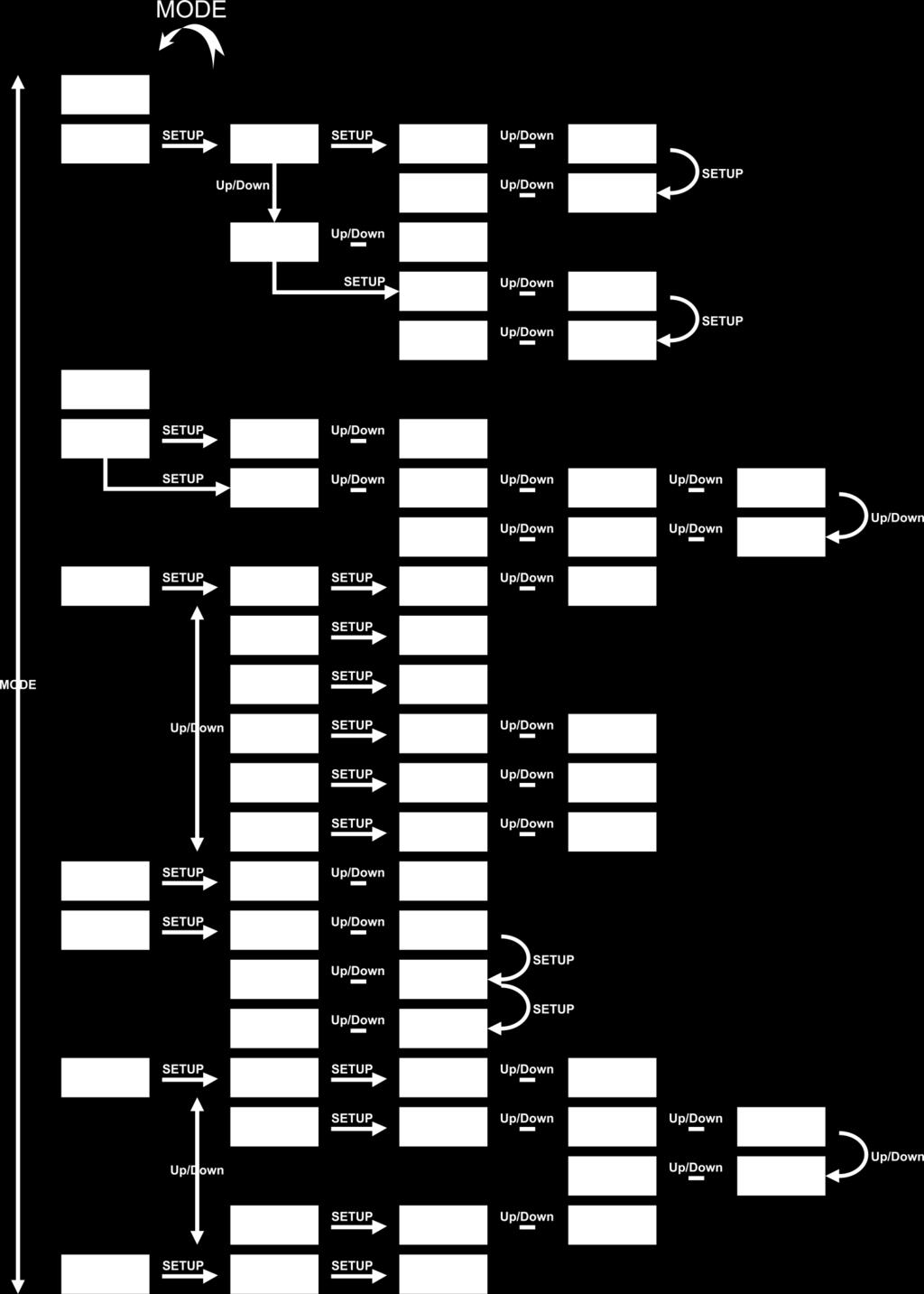
18 Menu Overview 17
19 Main Menu Options Auto Built-in programs Master/Slave DMX-512 Network settings Sound-controlled Static Colors Settings Sotware Information 1. Auto With this menu, you can set Auto mode. 01) Press the MODE button until the display shows. 02) The device will now run all built-in programs in sequence. 2. Built-in programs With this menu, you can set the built-in programs. 01) Press the MODE button until the display shows. 02) Press the SETUP button to open the menu. 03) Press the UP/DOWN buttons to choose the desired built-in program. The adjustment range is between. 04) Press the UP/DOWN buttons until the display shows 05) Press the SETUP button to enter and to toggle between the 2 options below. Once you have chosen the desired option, do as follows: Color (Press the UP/DOWN buttons to choose one of the 39 color presets.) Strobe (Press the UP/DOWN buttons to set strobe frequency. The adjustment range is between 0-99, from OFF to high frequency.) 06) Once you have adjusted the settings, press the SETUP button to confirm. 07) Return to step 4 and choose one of the programs from the range:. 18
20 08) Press the SETUP button to enter and to toggle between the 2 options below. Once you have chosen the desired option, do as follows: Program speed (Press the UP/DOWN buttons to increase/decrease program speed. The adjustment range is between 1-100, from slow to fast.) Strobe (Press the UP/DOWN buttons to set strobe frequency. The adjustment range is between 0-99, from OFF to high frequency.) 09) Once you have adjusted the settings, press the SETUP button to confirm. 3. Master/Slave With this menu you can set the device as a master or a slave device. 01) Press the MODE button until the display shows. 02) The device is now operating in slave mode and will react the same as the master device. 4. DMX-512 With this menu you can set the device s DMX starting address and the desired DMX channel mode. 01) Press the MODE button until the display shows. 02) Press the SETUP button to open the menu. 03) Press the UP/DOWN buttons to set the desired DMX starting address. The adjustment range is between. 04) Press the SETUP button again to proceed to channel mode settings. 05) Press the UP/DOWN buttons to choose one of the 7 DMX channel modes: 6CH, 8CH, 14CH, 26CH, 50CH, 192CH or 208CH. 06) Press the SETUP button to confirm. 5. Network Settings With this menu, you can adjust the device s properties, such as the IP address, subnet mask and the universes. 01) Press the MODE button until the display shows. 02) Press the SETUP button to open the menu. 03) Press the UP/DOWN buttons to toggle between the 6 options below Signal source With this menu you can select thed esired signal source: DMX or ArtNet. 01) Press the UP/DOWN buttons until the display shows. 02) Press the SETUP button to open the menu. 03) Press the UP/DOWN buttons to choose between DMX or ArtNet. 04) Press the SETUP button to confirm. 05) If you have chosen ArtNet, press the MODE button until the display shows, for the signal to be received properly. Otherwise, the device will not function in ArtNet mode IP address With this menu you can set the IP address. 01) Press the UP/DOWN buttons until the display shows. 02) Press the SETUP button to open the menu. The display will show. 03) Repeatedly press the SETUP button to skip to the desired section of the IP address (the currently selected section will blink). 04) Press the UP/DOWN buttons to set the values. 05) Press the SETUP button to confirm. 19
21 5.3. Net Mask With this menu you can set the net mask number. 01) Press the UP/DOWN buttons until the display shows. 02) Press the SETUP button to open the menu. The display will show. 03) Repeatedly press the SETUP button to skip to the desired section of the net mask (the currently selected section will blink). 04) Press the UP/DOWN buttons to set the values. 05) Press the SETUP button to confirm Net With this menu you can set the net number. 01) Press the UP/DOWN buttons until the display shows. 02) Press the SETUP button to open the menu. 03) Press the UP/DOWN buttons to set the net value. The adjustment range is between. 04) Press the SETUP button to confirm Subnet With this menu you can set the subnet number. 01) Press the UP/DOWN buttons until the display shows. 02) Press the SETUP button to open the menu. 03) Press the UP/DOWN buttons to set the subnet value. The adjustment range is between. 04) Press the SETUP button to confirm Universe With this menu you can set the universe number. 01) Press the UP/DOWN buttons until the display shows. 02) Press the SETUP button to open the menu. 03) Press the UP/DOWN buttons to set the universe value. The adjustment range is between. 04) Press the SETUP button to confirm. 6. Sound-controlled With this menu you can set sound-controlled mode. 01) Press the MODE button until the display shows. 02) Press the UP/DOWN buttons to set the sound sensitivity. The adjustment range is between, from OFF to high sound sensitivity. 03) Press the SETUP button to confirm. 04) The device will now react to the beat of the background music. 20
22 7. Static Colors With this menu you can set the device s static colors. 01) Press the MODE button until the display shows. 02) Press the SETUP button to open the menu. 03) Repeatedly press the SETUP button to toggle between 3 colors: Red, Green and Blue. 04) Once you have chosen the desired color, press the UP/DOWN buttons to set color brightness. The adjustment range for each color is between 0-255, from dark to brightest. 05) You can combine Red, Green and Blue (0-255) to create an infinite range of colors. 8. Settings With this menu you can adjust the device s settings. 01) Press the MODE button until the display shows. 02) Press the SETUP button to open the menu. 03) Press the UP/DOWN buttons to choose one of the 3 options below DMX error menu With this menu you can determine the device s behavior in case of a DMX signal error. 01) When the display shows, press the SETUP button to open the menu. 02) Press the UP/DOWN buttons to choose between OFF and HOLD. 03) If you have chosen OFF, the device will blackout its output, when a DMX signal error occurs. 04) If you have chosen HOLD, the device will fall back on the last properly working DMX signal from before the DMX signal error, which ensures undisrupted performance. 05) Press the SETUP button to confirm Display settings 01) When the display shows, press the SETUP button to open the menu. 02) Press the UP/DOWN buttons to choose one of the following options: 10s, 20s, 30s, 60s (the display will turn off when no button is pressed within the preset amount of time) or ON (the display will remain continuously on) Reset With this menu you can restore the factory settings. 01) When the display shows, press the SETUP button to open the menu. 02) Press the UP/DOWN buttons to choose between YES and NO. 03) If you have chosen YES, press the SETUP button to confirm. The device will now restore the default settings and will return to the main menu. 04) If you have chosen NO, press the SETUP button to ocnfirm and the device will return to the previous menu. 9. Software Information With this menu you can monitor the current software version. 01) Press the MODE button until the display shows. 02) Press the SETUP button to open the menu. The display will show. 03) Press the SETUP button again to view the software version. The display will show. 21
23 DMX Channels 6 channels Channel 1 Color Macros 0-5 Not functional 6-11 Color Color Color Color Color Color Color Color Color Color Color Color Color Color Color Color Color Color Color Color Color Color Color Color Color Color Color Color Color Color Color Color Color Color Color Color Color Color Color 39 Channel 2 Red CH1 must be closed Gradual adjustment Red, from 0-100% Channel 3 Green CH1 must be closed Gradual adjustment Green, from 0-100% Channel 4 Blue CH1 must be closed Gradual adjustment Blue, from 0-100% Channel 5 Strobe 0-4 Not functional Strobe frequency, from low to high frequency 22
24 Channel 6 Sound sensitivity Sound sensitivity adjustment, from OFF to high sensitivity 8 channels Channel 1 Dimmer Dimmer intensity, from dark to bright Channel 2 Strobe 0-4 Not functional Strobe frequency, from low to high frequency Channel 3 Built-in programs Dimmer must be open 0 Not functional 1-11 Program Program Program Program Program Program Program Program Program Program Program Program Program Program Program Program Program Program Program Program Sound-controlled mode Channel 4 Program speed CH3 must be set between Speed adjustment, from slow to fast Channel 4 Sound sensitivity CH3 must be set between Sound sensitivity adjustment, from low to high sensitivity Channel 5 Color Macros Dimmer must be open and CH3 must be closed 0-5 Not functional 6-11 Color Color Color Color Color Color Color Color Color Color Color Color 12 23
25 78-83 Color Color Color Color Color Color Color Color Color Color Color Color Color Color Color Color Color Color Color Color Color Color Color Color Color Color Color 39 Channel 6 Red Dimmer must be open and CH3 must be closed Gradual adjustment Red, from 0-100% Channel 7 Green Dimmer must be open and CH3 must be closed Gradual adjustment Green, from 0-100% Channel 8 Blue Dimmer must be open and CH3 must be closed Gradual adjustment Blue, from 0-100% 24
26 14 channels Channel 1 Built-in programs 0 Not functional 1-11 Program Program Program Program Program Program Program Program Program Program Program Program Program Program Program Program Program Program Program Program Sound-controlled mode Channel 2 Program speed CH1 must be set between Speed adjustment, from slow to fast Channel 2 Sound sensitivity CH1 must be set between Sound sensitivity adjustment, from low to high sensitivity Channel 3 Dimmer, LED strips Dimmer intensity, from dark to bright Channel 4 Strobe, LED strips Not functional Strobe frequency, from low to high frequency Channel 5 Color Macros, LED strips Not functional 6-11 Color Color Color Color Color Color Color Color Color Color Color Color Color Color Color Color 16 CH3 must be open and CH1 must be closed 25
27 Color Color Color Color Color Color Color Color Color Color Color Color Color Color Color Color Color Color Color Color Color Color Color 39 Channel 6 Red, LED strips 1 4 CH3 must be open, CH5 must be closed Gradual adjustment Red, from 0-100% Channel 7 Green, LED strips 1 4 CH3 must be open, CH5 must be closed Gradual adjustment Green, from 0-100% Channel 8 Blue, LED strips 1 4 CH3 must be open, CH5 must be closed Gradual adjustment Blue, from 0-100% Channel 9 Dimmer, LED strips Dimmer intensity, from dark to bright Channel 10 Strobe, LED strips Not functional Strobe frequency, from low to high frequency Channel 11 Color Macros, LED strips Not functional 6-11 Color Color Color Color Color Color Color Color Color Color Color Color Color Color 14 CH9 must be open and CH1 must be closed 26
28 90-95 Color Color Color Color Color Color Color Color Color Color Color Color Color Color Color Color Color Color Color Color Color Color Color Color Color 39 Channel 12 Red, LED strips 5 8 CH9 must be open, CH11 must be closed Gradual adjustment Red, from 0-100% Channel 13 Green, LED strips 5 8 CH9 must be open, CH11 must be closed Gradual adjustment Green, from 0-100% Channel 14 Blue, LED strips 5 8 CH9 must be open, CH11 must be closed Gradual adjustment Blue, from 0-100% 27
29 26 channels Channel 1 Built-in programs 0 Not functional 1-11 Program Program Program Program Program Program Program Program Program Program Program Program Program Program Program Program Program Program Program Program Sound-controlled mode Channel 2 Program speed CH1 must be set between Speed adjustment, from slow to fast Channel 2 Sound sensitivity CH1 must be set between Sound sensitivity adjustment, from low to high sensitivity Channel 3 Dimmer, LED strips Dimmer intensity, from dark to bright Channel 4 Strobe, LED strips Not functional Strobe frequency, from low to high frequency Channel 5 Color Macros, LED strips Not functional 6-11 Color Color Color Color Color Color Color Color Color Color Color Color Color Color Color Color 16 CH3 must be open and CH1 must be closed 28
30 Color Color Color Color Color Color Color Color Color Color Color Color Color Color Color Color Color Color Color Color Color Color Color 39 Channel 6 Red, LED strips 1 2 CH3 must be open, CH1 and CH5 must be closed Gradual adjustment Red, from 0-100% Channel 7 Green, LED strips 1 2 CH3 must be open, CH1 and CH5 must be closed Gradual adjustment Green, from 0-100% Channel 8 Blue, LED strips 1 2 CH3 must be open, CH1 and CH5 must be closed Gradual adjustment Blue, from 0-100% Channel 9 Dimmer, LED strips Dimmer intensity, from dark to bright Channel 10 Strobe, LED strips Not functional Strobe frequency, from low to high frequency Channel 11 Color Macros, LED strips Not functional 6-11 Color Color Color Color Color Color Color Color Color Color Color Color Color Color 14 CH9 must be open and CH1 must be closed 29
31 90-95 Color Color Color Color Color Color Color Color Color Color Color Color Color Color Color Color Color Color Color Color Color Color Color Color Color 39 Channel 12 Red, LED strips 3 4 CH9 must be open, CH1 and CH11 must be closed Gradual adjustment Red, from 0-100% Channel 13 Green, LED strips 3 4 CH9 must be open, CH1 and CH11 must be closed Gradual adjustment Green, from 0-100% Channel 14 Blue, LED strips 3 4 CH9 must be open, CH1 and CH11 must be closed Gradual adjustment Blue, from 0-100% Channel 15 Dimmer, LED strips Dimmer intensity, from dark to bright Channel 16 Strobe, LED strips Not functional Strobe frequency, from low to high frequency Channel 17 Color Macros, LED strips Not functional 6-11 Color Color Color Color Color Color Color Color Color Color Color Color 12 CH15 must be open and CH1 must be closed 30
32 78-83 Color Color Color Color Color Color Color Color Color Color Color Color Color Color Color Color Color Color Color Color Color Color Color Color Color Color Color 39 Channel 18 Red, LED strips 5 6 CH15 must be open, CH1 and CH17 must be closed Gradual adjustment Red, from 0-100% Channel 19 Green, LED strips 5 6 CH15 must be open, CH1 and CH17 must be closed Gradual adjustment Green, from 0-100% Channel 20 Blue, LED strips 5 6 CH15 must be open, CH1 and CH17 must be closed Gradual adjustment Blue, from 0-100% Channel 21 Dimmer, LED strips Dimmer intensity, from dark to bright Channel 22 Strobe, LED strips Not functional Strobe frequency, from low to high frequency Channel 23 Color Macros, LED strips Not functional 6-11 Color Color Color Color Color Color Color Color Color Color 10 CH21 must be open and CH1 must be closed 31
33 66-71 Color Color Color Color Color Color Color Color Color Color Color Color Color Color Color Color Color Color Color Color Color Color Color Color Color Color Color Color Color 39 Channel 24 Red, LED strips 7 8 CH21 must be open, CH1 and CH23 must be closed Gradual adjustment Red, from 0-100% Channel 25 Green, LED strips 7 8 CH21 must be open, CH1 and CH23 must be closed Gradual adjustment Green, from 0-100% Channel 26 Blue, LED strips 7 8 CH21 must be open, CH1 and CH23 must be closed Gradual adjustment Blue, from 0-100% 32
34 50 channels Channel 1 Built-in programs 0 Not functional 1-11 Program Program Program Program Program Program Program Program Program Program Program Program Program Program Program Program Program Program Program Program Sound-controlled mode Channel 2 Program speed CH1 must be set between Speed adjustment, from slow to fast Channel 2 Sound sensitivity CH1 must be set between Sound sensitivity adjustment, from low to high sensitivity Channel 3 Dimmer, LED strip Dimmer intensity, from dark to bright Channel 4 Strobe, LED strip Not functional Strobe frequency, from low to high frequency Channel 5 Color Macros, LED strip Not functional 6-11 Color Color Color Color Color Color Color Color Color Color Color Color Color Color Color Color 16 CH3 must be open and CH1 must be closed 33
35 Color Color Color Color Color Color Color Color Color Color Color Color Color Color Color Color Color Color Color Color Color Color Color 39 Channel 6 Red, LED strip 1 CH3 must be open, CH1 and CH5 must be closed Gradual adjustment Red, from 0-100% Channel 7 Green, LED strip 1 CH3 must be open, CH1 and CH5 must be closed Gradual adjustment Green, from 0-100% Channel 8 Blue, LED strip 1 CH3 must be open, CH1 and CH5 must be closed Gradual adjustment Blue, from 0-100% Channel 9 Dimmer, LED strip Dimmer intensity, from dark to bright Channel 10 Strobe, LED strip Not functional Strobe frequency, from low to high frequency Channel 11 Color Macros, LED strip Not functional 6-11 Color Color Color Color Color Color Color Color Color Color Color Color Color Color 14 CH9 must be open and CH1 must be closed 34
36 90-95 Color Color Color Color Color Color Color Color Color Color Color Color Color Color Color Color Color Color Color Color Color Color Color Color Color 39 Channel 12 Red, LED strip 2 CH9 must be open, CH1 and CH11 must be closed Gradual adjustment Red, from 0-100% Channel 13 Green, LED strip 2 CH9 must be open, CH1 and CH11 must be closed Gradual adjustment Green, from 0-100% Channel 14 Blue, LED strip 2 CH9 must be open, CH1 and CH11 must be closed Gradual adjustment Blue, from 0-100% Channel 15 Dimmer, LED strip Dimmer intensity, from dark to bright Channel 16 Strobe, LED strip Not functional Strobe frequency, from low to high frequency Channel 17 Color Macros, LED strip Not functional 6-11 Color Color Color Color Color Color Color Color Color Color Color Color 12 CH15 must be open and CH1 must be closed 35
37 78-83 Color Color Color Color Color Color Color Color Color Color Color Color Color Color Color Color Color Color Color Color Color Color Color Color Color Color Color 39 Channel 18 Red, LED strip 3 CH15 must be open, CH1 and CH17 must be closed Gradual adjustment Red, from 0-100% Channel 19 Green, LED strip 3 CH15 must be open, CH1 and CH17 must be closed Gradual adjustment Green, from 0-100% Channel 20 Blue, LED strip 3 CH15 must be open, CH1 and CH17 must be closed Gradual adjustment Blue, from 0-100% Channel 21 Dimmer, LED strip Dimmer intensity, from dark to bright Channel 22 Strobe, LED strip Not functional Strobe frequency, from low to high frequency Channel 23 Color Macros, LED strip Not functional 6-11 Color Color Color Color Color Color Color Color Color Color 10 CH21 must be open and CH1 must be closed 36
38 66-71 Color Color Color Color Color Color Color Color Color Color Color Color Color Color Color Color Color Color Color Color Color Color Color Color Color Color Color Color Color 39 Channel 24 Red, LED strip 4 CH21 must be open, CH1 and CH23 must be closed Gradual adjustment Red, from 0-100% Channel 25 Green, LED strip 4 CH21 must be open, CH1 and CH23 must be closed Gradual adjustment Green, from 0-100% Channel 26 Blue, LED strip 4 CH21 must be open, CH1 and CH23 must be closed Gradual adjustment Blue, from 0-100% Channel 27 Dimmer, LED strip Dimmer intensity, from dark to bright Channel 28 Strobe, LED strip Not functional Strobe frequency, from low to high frequency Channel 29 Color Macros, LED strip Not functional 6-11 Color Color Color Color Color Color Color Color 8 CH27 must be open and CH1 must be closed 37
39 54-59 Color Color Color Color Color Color Color Color Color Color Color Color Color Color Color Color Color Color Color Color Color Color Color Color Color Color Color Color Color Color Color 39 Channel 30 Red, LED strip 5 CH27 must be open, CH1 and CH29 must be closed Gradual adjustment Red, from 0-100% Channel 31 Green, LED strip 5 CH27 must be open, CH1 and CH29 must be closed Gradual adjustment Green, from 0-100% Channel 32 Blue, LED strip 5 CH27 must be open, CH1 and CH29 must be closed Gradual adjustment Blue, from 0-100% Channel 33 Dimmer, LED strip Dimmer intensity, from dark to bright Channel 34 Strobe, LED strip Not functional Strobe frequency, from low to high frequency Channel 35 Color Macros, LED strip Not functional 6-11 Color Color Color Color Color Color 6 CH33 must be open and CH1 must be closed 38
40 42-47 Color Color Color Color Color Color Color Color Color Color Color Color Color Color Color Color Color Color Color Color Color Color Color Color Color Color Color Color Color Color Color Color Color 39 Channel 36 Red, LED strip 6 CH33 must be open, CH1 and CH35 must be closed Gradual adjustment Red, from 0-100% Channel 37 Green, LED strip 6 CH33 must be open, CH1 and CH35 must be closed Gradual adjustment Green, from 0-100% Channel 38 Blue, LED strip 6 CH33 must be open, CH1 and CH35 must be closed Gradual adjustment Blue, from 0-100% Channel 39 Dimmer, LED strip Dimmer intensity, from dark to bright Channel 40 Strobe, LED strip Not functional Strobe frequency, from low to high frequency Channel 41 Color Macros, LED strip Not functional 6-11 Color Color Color Color 4 CH39 must be open and CH1 must be closed 39
41 30-35 Color Color Color Color Color Color Color Color Color Color Color Color Color Color Color Color Color Color Color Color Color Color Color Color Color Color Color Color Color Color Color Color Color Color Color 39 Channel 42 Red, LED strip 7 CH39 must be open, CH1 and CH41 must be closed Gradual adjustment Red, from 0-100% Channel 43 Green, LED strip 7 CH39 must be open, CH1 and CH41 must be closed Gradual adjustment Green, from 0-100% Channel 44 Blue, LED strip 7 CH39 must be open, CH1 and CH41 must be closed Gradual adjustment Blue, from 0-100% Channel 45 Dimmer, LED strip Dimmer intensity, from dark to bright Channel 46 Strobe, LED strip Not functional Strobe frequency, from low to high frequency 40
42 Channel 47 Color Macros, LED strip Not functional 6-11 Color Color Color Color Color Color Color Color Color Color Color Color Color Color Color Color Color Color Color Color Color Color Color Color Color Color Color Color Color Color Color Color Color Color Color Color Color Color Color 39 CH45 must be open and CH1 must be closed Channel 48 Red, LED strip 8 CH45 must be open, CH1 and CH47 must be closed Gradual adjustment Red, from 0-100% Channel 49 Green, LED strip 8 CH45 must be open, CH1 and CH47 must be closed Gradual adjustment Green, from 0-100% Channel 50 Blue, LED strip 8 CH45 must be open, CH1 and CH47 must be closed Gradual adjustment Blue, from 0-100% 41
43 192 channels There are 8 LED strips connected to the Octostrip. Each LED strip is divided into 8 separate sections. Each section is equipped with 3 color LEDs (RGB). 8 LED strips x 8 sections x 3 colors = 192 channels. Channel 1 Red, LED strip 1, section Gradual adjustment Red, from 0-100% Channel 2 Green, LED strip 1, section Gradual adjustment Green, from 0-100% Channel 3 Blue, LED strip 1, section Gradual adjustment Blue, from 0-100% Channel 4 Red, LED strip 1, section Gradual adjustment Red, from 0-100% Channel 5 Green, LED strip 1, section Gradual adjustment Green, from 0-100% Channel 6 Blue, LED strip 1, section Gradual adjustment Blue, from 0-100% Channel 7 Red, LED strip 1, section Gradual adjustment Red, from 0-100% Channel 8 Green, LED strip 1, section Gradual adjustment Green, from 0-100% Channel 9 Blue, LED strip 1, section Gradual adjustment Blue, from 0-100% Channel 190 Red, LED strip 8, section Gradual adjustment Red, from 0-100% Channel 191 Green, LED strip 8, section Gradual adjustment Green, from 0-100% Channel 192 Blue, LED strip 8, section Gradual adjustment Blue, from 0-100% 42
44 208 channels There are 8 LED strips connected to the Octostrip. Each LED strip has its own dimmer and strobe. Each LED strip is divided into 8 separate sections. Each section is equipped with 3 color LEDs (RGB). 8 LED strips x 8 sections x 3 colors + 8 dimmers + 8 strobes = 208 channels. Channel 1 Dimmer, LED strip Dimmer intensity, from dark to bright Channel 2 Strobe, LED strip Not functional Strobe frequency, from low to high frequency Channel 3 Dimmer, LED strip Dimmer intensity, from dark to bright Channel 4 Strobe, LED strip Not functional Strobe frequency, from low to high frequency Channel 5 Dimmer, LED strip Dimmer intensity, from dark to bright Channel 6 Strobe, LED strip Not functional Strobe frequency, from low to high frequency Channel 7 Dimmer, LED strip Dimmer intensity, from dark to bright Channel 8 Strobe, LED strip Not functional Strobe frequency, from low to high frequency Channel 9 Dimmer, LED strip Dimmer intensity, from dark to bright Channel 10 Strobe, LED strip Not functional Strobe frequency, from low to high frequency Channel 11 Dimmer, LED strip Dimmer intensity, from dark to bright Channel 12 Strobe, LED strip Not functional Strobe frequency, from low to high frequency Channel 13 Dimmer, LED strip Dimmer intensity, from dark to bright 43
45 Channel 14 Strobe, LED strip Not functional Strobe frequency, from low to high frequency Channel 15 Dimmer, LED strip Dimmer intensity, from dark to bright Channel 16 Strobe, LED strip Not functional Strobe frequency, from low to high frequency Channel 17 Red, LED strip 1, section 1 CH1 must be open Gradual adjustment Red, from 0-100% Channel 18 Green, LED strip 1, section 1 CH1 must be open Gradual adjustment Green, from 0-100% Channel 19 Blue, LED strip 1, section 1 CH1 must be open Gradual adjustment Blue, from 0-100% Channel 20 Red, LED strip 1, section 2 CH1 must be open Gradual adjustment Red, from 0-100% Channel 21 Green, LED strip 1, section 2 CH1 must be open Gradual adjustment Green, from 0-100% Channel 22 Blue, LED strip 1, section 2 CH1 must be open Gradual adjustment Blue, from 0-100% Channel 23 Red, LED strip 1, section 3 CH1 must be open Gradual adjustment Red, from 0-100% Channel 24 Green, LED strip 1, section 3 CH1 must be open Gradual adjustment Green, from 0-100% Channel 25 Blue, LED strip 1, section 3 CH1 must be open Gradual adjustment Blue, from 0-100% Channel 206 Red, LED strip 8, section 8 CH15 must be open Gradual adjustment Red, from 0-100% Channel 207 Green, LED strip 8, section 8 CH15 must be open Gradual adjustment Green, from 0-100% Channel 208 Blue, LED strip 8, section 8 CH15 must be open Gradual adjustment Blue, from 0-100% 44
46 Maintenance The operator has to make sure that safety-related and machine-technical installations are to be inspected by an expert after every year in the course of an acceptance test. The operator has to make sure that safety-related and machine-technical installations are to be inspected by a skilled person once a year. The following points have to be considered during the inspection: 01) All screws used for installing the device or parts of the device have to be tightly connected and must not be corroded. 02) There may not be any deformations on housings, fixations and installation spots. 03) Mechanically moving parts like axles, eyes and others may not show any traces of wearing. 04) The electric power supply cables must not show any damages or material fatigue. The LED Octostrip Set MKII requires almost no maintenance. However, you should keep the unit clean. Otherwise, the fixture s light output will be significantly reduced. Disconnect the mains power supply, and then wipe the cover with a damp cloth. Do not immerse in liquid. Do not use alcohol or solvents. Please clean internal components once a year with a light brush and vacuum cleaner. Keep connections clean. Disconnect electric power, and then wipe the DMX connections with a damp cloth. Make sure connections are thoroughly dry before linking equipment or supplying electric power. Replacing the Fuse Power surges, short-circuit or inappropriate electrical power supply may cause a fuse to burn out. If the fuse burns out, the product will not function whatsoever. If this happens, follow the directions below to do so. 01) Unplug the unit from electric power source. 02) Insert a screwdriver into the slot in the fuse cover. Turn the fuse holder counterclockwise. The fuse will come out. 03) Remove the used fuse. If brown or unclear, it is burned out. 04) Insert the replacement fuse into the holder where the old fuse was. Reinsert the fuse holder. Be sure to use a fuse of the same type and specification. See the product specification label for details. Troubleshooting This troubleshooting guide is meant to help solve simple problems. If a problem occurs, carry out the steps below in sequence until a solution is found. Once the unit operates properly, do not carry out following steps. No Light If the light effect does not operate properly, refer servicing to a technician. Suspect three potential problem areas as: the power supply, the fuse and the LEDs. 01) Power supply. Check that the unit is plugged into an appropriate power supply. 02) The fuse. Replace the fuse. See page 45 for replacing the fuse. 03) The LEDs. Return the LED Octostrip Set MKII to your Showtec dealer. 04) If all of the above appears to be O.K., plug the unit in again. 05) If you are unable to determine the cause of the problem, do not open the Controller, as this may damage the unit and the warranty will become void. 06) Return the device to your Showtec dealer. 45
47 No Response to DMX Suspect the DMX cable or connectors, a controller malfunction, a light effect DMX card malfunction. 01) Check the DMX setting. Make sure that DMX addresses are correct. 02) Check the DMX cable: Unplug the unit; change the DMX cable; then reconnect to electrical power. Try your DMX control again. 03) Determine whether the controller or light effect is at fault. Does the controller operate properly with other DMX products? If not, take the controller in for repair. If so, take the DMX cable and the light effect to a qualified technician. Problem Probable cause(s) Solution One or more fixtures do not function at all Fixtures reset correctly, but all respond erratically or not at all to the controller Fixtures reset correctly, but some respond erratically or not at all to the controller No light or LEDs cut out intermittently No power to the fixture Check if power is switched on and cables are plugged in Primary fuse blown Replace the fuse. The controller is not connected. Connect controller. 3-pin XLR Out of the controller Install a phase reversing cable does not match XLR Out of the first between the controller and the fixture on the link (i.e. signal is first fixture on the link reversed) Check data quality. If much lower than 100 percent, the problem may be a bad data link Poor data quality connection, poor quality or broken cables, missing termination plug, or a defective fixture disturbing the link Inspect connections and cables. Bad data link connection Correct poor connections. Repair or replace damaged cables Data link not terminated with 120 Insert termination plug in output Ohm termination plug jack of the last fixture on the link Incorrect addressing of the fixtures Check address setting One of the fixtures is defective and disturbs data transmission on the link 3-pin XLR Out on the fixtures does not match (pins 2 and 3 reversed) Bypass one fixture at a time until normal operation is restored: unplug both connectors and connect them directly together. Have the defective fixture serviced by a qualified technician Install a phase-reversing cable between the fixtures or swap pin 2 and 3 in the fixture that behaves erratically Fixture is too hot Allow the fixture to cool down Make sure air vents are not blocked Turn up the air conditioning Disconnect the fixture and return it LEDs damaged to your dealer The power supply settings do not match local AC voltage and frequency Disconnect fixture. Check settings and correct if necessary 46
48 Product Specifications Model: Input voltage: Power consumption: DMX linking: Fuse: Dimensions (controller): Dimensions (LED strip): Weight (controller): Weight (8 x LED strips): Showtec LED Octostrip Set MKII V AC, 60/50Hz 90W (full output) 30pcs T2L/250V 200 x 315 x 92 mm (LxWxH) 1025 x 30 x 50 mm (LxWxH) 2,3 kg 8 x 1,4 kg Operating and Programming: Signal pin OUT: Pin 1 (earth), pin 2 (-), pin 3 (+) DMX Mode: 6, 8, 14, 26, 50, 192, 208 channels Signal input: 3-pin DMX/RJ45 IN Signal output: 3-pin DMX/RJ45 OUT LED strip output: 5-pin XLR OUT Electro-mechanical effects: Dimmer: 0-100% Strobe: 0-20Hz Housing: Die-cast aluminum Control protocol: DMX-512, ArtNet DMX control: via standard DMX-controller Onboard: LCD display for easy setup Control: Auto, Built-in programs, Sound-controlled, Static Colors, Master/Slave, DMX/ArtNet IP rating: IP20 Connections: Dedicated Pro power to Schuko & data connector Cooling: Convection Max. ambient temperature ta: 40 C Max. housing temperature tb: 80 C Minimum distance: Minimum distance from flammable surfaces: Minimum distance to lighted object: 0,5 m 1 m Design and product specifications are subject to change without prior notice. Website: service@highlite.nl 47
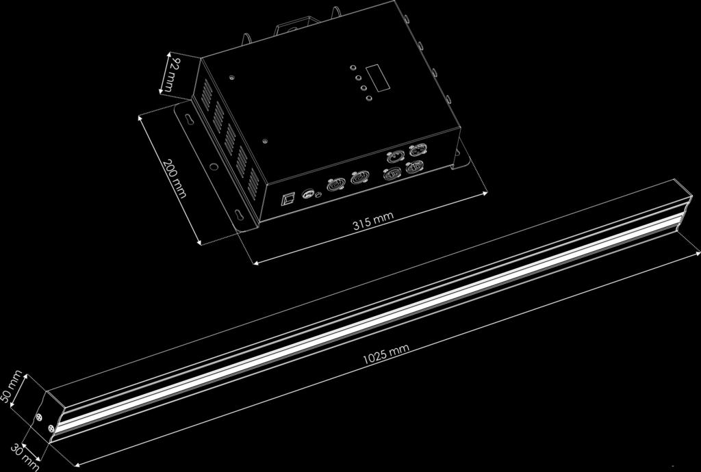
49 Dimensions 48
50 Notes 49
51 50


52 2016 Showtec
LED Pixel Track V3 ORDERCODE 42200
 LED Pixel Track V3 ORDERCODE 42200 Congratulations! You have bought a great, innovative product from Showtec. The Showtec LED Pixel Track brings excitement to any venue. Whether you want simple plug-&-play
ENGLISH Optic Fiber Double
 MANUAL ENGLISH Double V1 Highlite International B.V. Vestastraat 2 6468 EX Kerkrade the Netherlands Table of contents Warning... 2 Safety Instructions... 2 Operating Determinations... 4 Rigging... 4 Connection
ENGLISH LED Operator 6
 MANUAL ENGLISH V2 Highlite International B.V. Vestastraat 2 6468 EX Kerkrade the Netherlands Table of contents Warning... 2 Unpacking Instructions... 2 Safety Instructions... 2 Operating Determinations...
ENGLISH Helios 200 COB Q4
 MANUAL ENGLISH Helios 200 COB Q4 V3 Highlite International B.V. Vestastraat 2 6468 EX Kerkrade the Netherlands Table of contents Warning... 2 Safety Instructions... 2 Operating Determinations... 4 Rigging...
LED Par 56 Short Eco V2 ORDERCODE 42417
 LED Par 56 Short Eco V2 ORDERCODE 42417 Congratulations! You have bought a great, innovative product from Showtec. The Showtec LED Par 56 brings excitement to any venue. Whether you want simple plug-&-play
LED Floodlight 6x 1W, 40 ORDERCODE ORDERCODE ORDERCODE ORDERCODE ORDERCODE ORDERCODE 42760
 LED Floodlight 6x 1W, 40 ORDERCODE 42755 ORDERCODE 42756 ORDERCODE 42757 ORDERCODE 42758 ORDERCODE 42759 ORDERCODE 42760 Congratulations! You have bought a great, innovative product from Showtec. The Showtec
VGAD-12 ORDERCODE
 VGAD-12 ORDERCODE 101220 Congratulations! You have bought a great, innovative product from DMT. The DMT Media Spinner brings excitement to any venue. Whether you want simple plug-&-play action or a sophisticated
Pixel Bubble 80 ORDERCODE 41092
 Pixel Bubble 80 ORDERCODE 41092 Highlite International B.V. Vestastraat 2 6468 EX Kerkrade The Netherlands Phone: +31 45-5667700 Congratulations! You have bought a great, innovative product from Showtec.
LED Par 56 Short Eco V2 ORDERCODE 42417
 LED Par 56 Short Eco V2 ORDERCODE 42417 Congratulations! You have bought a great, innovative product from Showtec. The Showtec LED Par 56 brings excitement to any venue. Whether you want simple plug-&-play
ENGLISH Pixel Bar 12 MKII
 MANUAL ENGLISH Pixel Bar 12 MKII V1 Highlite International B.V. Vestastraat 2 6468 EX Kerkrade the Netherlands Table of contents Warning... 2 Safety Instructions... 2 Operating Determinations... 4 Rigging...
ENGLISH Antenna Distributor
 MANUAL ENGLISH Antenna Distributor V1 Highlite International B.V. Vestastraat 2 6468 EX Kerkrade the Netherlands Table of contents Warning... 2 Safety Instructions... 2 Operating Determinations... 4 Connection
Ignitor-6 Section Strobe ORDERCODE 40292
 Ignitor-6 Section Strobe ORDERCODE 40292 Highlite International B.V. Vestastraat 2 6468 EX Kerkrade The Netherlands Phone: +31 45-5667700 Congratulations! You have bought a great, innovative product from
Aircone LED 1W ORDERCODE 40313
 Aircone LED 1W ORDERCODE 40313 Highlite International B.V. Vestastraat 2 6468 EX Kerkrade The Netherlands Phone: +31 45-5667700 Congratulations! You have bought a great, innovative product from Showtec.
ENGLISH Dancefloor Sparkle RGB
 MANUAL ENGLISH V1 Highlite International B.V. Vestastraat 2 6468 EX Kerkrade the Netherlands Table of contents Warning... 2 Safety Instructions... 2 Operating Determinations... 4 Connection with the mains...
ENGLISH Spectral M800 Q4 IP65
 MANUAL ENGLISH Spectral M800 Q4 IP65 V1 Highlite International B.V. Vestastraat 2 6468 EX Kerkrade the Netherlands Table of contents Warning... 3 Safety Instructions... 3 Operating Determinations... 5
Studiobeam Tour Q4 4-in-1 LED ORDERCODE 42485
 Studiobeam Tour Q4 4-in-1 LED ORDERCODE 42485 Highlite International B.V. Vestastraat 2 6468 EX Kerkrade The Netherlands Phone: +31 45-5667700 Congratulations! You have bought a great, innovative product
MANUAL. ENGLISH NanoQ 19 Q4 IP Ordercode: Highlite International B.V. Vestastraat EX Kerkrade the Netherlands
 MANUAL ENGLISH V1 Highlite International B.V. Vestastraat 2 6468 EX Kerkrade the Netherlands Table of contents Warning... 3 Safety Instructions... 3 Operating Determinations... 5 Rigging... 5 Connection
ENGLISH Spectral M800 MKII
 MANUAL ENGLISH Spectral M800 MKII V1 Highlite International B.V. Vestastraat 2 6468 EX Kerkrade the Netherlands Table of contents Warning... 3 Safety Instructions... 3 Operating Determinations... 5 Rigging...
ENGLISH LED light bar 8
 MANUAL ENGLISH LED light bar 8 V2 Highlite International B.V. Vestastraat 2 6468 EX Kerkrade the Netherlands Table of contents Warning... 2 Safety Instructions... 2 Operating Determinations... 4 Rigging...
MANUAL. ENGLISH Galaxy 360. Ordercode: Highlite International B.V. Vestastraat EX Kerkrade the Netherlands
 MANUAL ENGLISH Galaxy 360 V1 Highlite International B.V. Vestastraat 2 6468 EX Kerkrade the Netherlands Table of contents Warning... 3 Safety Instructions... 3 Operating Determinations... 5 Rigging...
LED Light Bar 8 ORDERCODE 42199
 LED Light Bar 8 ORDERCODE 42199 Congratulations! You have bought a great, innovative product from Showtec. The Showtec LED Light Bar 8 brings excitement to any venue. Whether you want simple plug-&-play
LED Spere Direct Control 30 ORDERCODE 41125
 LED Spere Direct Control 30 ORDERCODE 41125 Congratulations! You have bought a great, innovative product from Showtec. The Showtec LED Sphere Direct Control 30 brings excitement to any venue. Whether you
ENGLISH Scanmaster 2 MKII
 MANUAL ENGLISH Scanmaster 2 MKII V1 Highlite International B.V. Vestastraat 2 6468 EX Kerkrade the Netherlands Table of contents Warning...2 Safety Instructions...2 Operating Determinations...3 Connection
LED Gobo Projector 25W ORDERCODE 40711
 LED Gobo Projector 25W ORDERCODE 40711 Highlite International B.V. Vestastraat 2 6468 EX Kerkrade The Netherlands Phone: +31 45-5667700 Congratulations! You have bought a great, innovative product from
LED Design Par 18 RGB ORDERCODE 42570
 LED Design Par 18 RGB ORDERCODE 42570 Congratulations! You have bought a great, innovative product from Showtec. The Showtec LED Design Par brings excitement to any venue. Whether you want simple plug-&-play
LED Operator 4 Air ORDERCODE 50726
 LED Operator 4 Air ORDERCODE 50726 Congratulations! You have bought a great, innovative product from Showtec. The Showtec LED Operator 4 Air brings excitement to any venue. Whether you want simple plug-&-play
K-112 ORDERCODE D3551
 K-112 ORDERCODE D31 Congratulations! You have bought a great, innovative product from DAP Audio. The DAP Audio K-112 brings excitement to any venue. Whether you want simple plug-&-play action or a sophisticated
MANUAL ENGLISH Showmaster 48 MKII V1 Ordercode: 50831
 MANUAL ENGLISH Showmaster 48 MKII V1 Highlite International B.V. Vestastraat 2 6468 EX Kerkrade the Netherlands Table of contents Warning... 2 Safety Instructions... 2 Operating Determinations... 3 Connection
Cameleon Bar 24-3 ORDERCODE 42695
 Cameleon Bar 24-3 ORDERCODE 42695 Congratulations! You have bought a great, innovative product from Showtec. The Showtec Cameleon Bar 24-3 brings excitement to any venue. Whether you want simple plug-&-play
LED Pixel Track Pro ORDERCODE 42205
 LED Pixel Track Pro ORDERCODE 42205 Congratulations! You have bought a great, innovative product from Showtec. The Showtec LED Pixel Track Pro brings excitement to any venue. Whether you want simple plug-&-play
Mini StudioBeam RGB ORDERCODE 42447
 Mini StudioBeam RGB ORDERCODE 42447 Congratulations! You have bought a great, innovative product from Showtec. The Showtec Mini StudioBeam RGB brings excitement to any venue. Whether you want simple plug-&-
Showdesigner 1024 ORDERCODE 50720
 Showdesigner 1024 ORDERCODE 50720 Congratulations! You have bought a great, innovative product from Showtec. The Showtec Showdesigner 1024 brings excitement to any venue. Whether you want simple plug-&-play
Mini StudioBeam RGB ORDERCODE 42447
 Mini StudioBeam RGB ORDERCODE 42447 V2 Congratulations! You have bought a great, innovative product from Showtec. The Showtec Mini StudioBeam RGB brings excitement to any venue. Whether you want simple
IM-53 Installation Mixer ORDERCODE D2178
 IM-53 Installation Mixer ORDERCODE D2178 Congratulations! You have bought a great, innovative product from DAP Audio. The DAP Audio IM-53 brings excitement to any venue. Whether you want simple plug-&-play
MANUAL ENGLISH Core Club Ordercode: D2314
 MANUAL ENGLISH Core Club Ordercode: Highlite International B.V. Vestastraat 2 6468 EX Kerkrade the Netherlands Table of contents Warning... 2 Unpacking Instructions... 2 Safety Instructions... 2 Operating
SM-8/2 ORDERCODE 50700
 SM-8/2 ORDERCODE 50700 Congratulations! You have bought a great, innovative product from Showtec. The Showtec SM-8/2 brings excitement to any venue. Whether you want simple plug-&-play action or a sophisticated
Tracker Q4 ORDERCODE 41388
 Tracker Q4 ORDERCODE 41388 Highlite International B.V. Vestastraat 2 6468 EX Kerkrade The Netherlands Phone: +31 45-5667700 Congratulations! You have bought a great, innovative product from Showtec. The
Arc-Bar 3 ORDERCODE 41350
 Arc-Bar 3 ORDERCODE 41350 Congratulations! You have bought a great, innovative product from Showtec. The Showtec Arc-Bar 3 brings excitement to any venue. Whether you want simple plug-&-play action or
Phantom 20 LED Beam ORDERCODE 40182
 Phantom 20 LED Beam ORDERCODE 40182 Highlite International B.V. Vestastraat 2 6468 EX Kerkrade The Netherlands Phone: +31 45-5667700 Congratulations! You have bought a great, innovative product from Showtec.
Spectra Batten (Order code: LEDJ95)
") www.prolight.co.uk Spectra Batten (Order code: LEDJ95) Safety WARNING FOR YOUR OWN SAFETY, PLEASE READ THIS USER MANUAL CAREFULLY BEFORE YOUR INITIAL START-UP! CAUTION! Keep this equipment away from rain,
www.prolight.co.uk Spectra Batten (Order code: LEDJ95) Safety WARNING FOR YOUR OWN SAFETY, PLEASE READ THIS USER MANUAL CAREFULLY BEFORE YOUR INITIAL START-UP! CAUTION! Keep this equipment away from rain,
Commander 384. w w w. p r o l i g h t. c o. u k U S E R M A N U A L
 Commander 384 w w w. p r o l i g h t. c o. u k U S E R M A N U A L 1, Before you begin 1.1: Safety warnings...2 3 1.2: What is included...4 1.3: Unpacking instructions...4 2, Introduction 2.1: Features...4
LED-BANK4 USER MANUAL. COLORbank 4
 LED-BANK4 COLORbank 4 USER MANUAL CHAUVET, 3000 N 29 th Ct, Hollywood, FL 33020 U.S.A (800) 762-084 (954) 929-5 FAX (954) 929-5560 www.chauvetlighting.com 2006-04-8/6:44 Table of Content BEFORE YOU BEGIN...
Dragonfly Quad. User Manual V1.4. Order code: EQLED101
 Dragonfly Quad User Manual V1.4 Order code: EQLED101 Safety advice WARNING FOR YOUR OWN SAFETY, PLEASE READ THIS USER MANUAL CAREFULLY BEFORE YOUR INITIAL START-UP! Before your initial start-up, please
ENGLISH Odin S-18A Line Array Sub
 MANUAL ENGLISH Odin S-18A Line Array Sub V1 Highlite International B.V. Vestastraat 2 6468 EX Kerkrade the Netherlands Table of contents Warning... 2 Safety Instructions... 2 Connection with the mains...
TRANSCENSION 6-CHANNEL DMX DIMMER PACK (order code: BOTE40) USER MANUAL
 USER MANUAL") www.prolight.co.uk TRANSCENSION 6-CHANNEL PACK (order code: BOTE40) USER MANUAL SAFETY WARNING FOR YOUR OWN SAFETY, PLEASE READ THIS USER MANUAL CAREFULLY BEFORE YOUR INITIAL START-UP! CAUTION! Keep this
www.prolight.co.uk TRANSCENSION 6-CHANNEL PACK (order code: BOTE40) USER MANUAL SAFETY WARNING FOR YOUR OWN SAFETY, PLEASE READ THIS USER MANUAL CAREFULLY BEFORE YOUR INITIAL START-UP! CAUTION! Keep this
Stratos Duo RGB. User Manual. Order code: EQLED371
 Stratos Duo RGB User Manual Order code: EQLED1 Safety advice WARNING FOR YOUR OWN SAFETY, PLEASE READ THIS USER MANUAL CAREFULLY BEFORE YOUR INITIAL START-UP! Before your initial start-up, please make
Phantom 140 LED Beam ORDERCODE 40194
 Phantom 140 LED Beam ORDERCODE 40194 Highlite International B.V. Vestastraat 2 6468 EX Kerkrade The Netherlands Phone: +31 45-5667700 Congratulations! You have bought a great, innovative product from Showtec.
ORDER CODE: EQLED65 USER MANUAL
 www.prolight.co.uk ORDER CODE: EQLED65 USER MANUAL Safety WARNING FOR YOUR OWN SAFETY, PLEASE READ THIS USER MANUAL CAREFULLY BEFORE YOUR INITIAL START-UP! CAUTION! Keep this equipment away from rain,
Professional RGB LED DMX Controller
 Professional RGB LED DMX Controller LC-8PRO Order No. 38.0010 INSTRUCTION MANUAL ELECTRONICS FOR SPECIALISTS ELECTRONICS FOR SPECIALISTS ELECTRONICS FOR SPECIALISTS ELECTRONICS FOR SPECIALISTS Warning...
ALO 030 MKII. 30 Watt DMX LED scanner. User manual
 ALO 030 MKII 30 Watt DMX LED scanner User manual Safety instructions WARNING! Always keep this device away from moisture and rain! Hazardous electrical shocks may occur! WARNING! Only connect this device
Fusion 120 Zoom. User Manual. Order code: EQLED068
 Fusion 120 Zoom User Manual Order code: EQLED068 Safety advice WARNING FOR YOUR OWN SAFETY, PLEASE READ THIS USER MANUAL CAREFULLY BEFORE YOUR INITIAL START-UP! Before your initial start-up, please make
LED-PAR200B USER MANUAL. COLORsplash 200B
 LED-PAR00B COLORsplash 00B USER MANUAL CHAUVET, 3000 N 9 th Ct, Hollywood, FL 3300 U.S.A (800) 76-084 (954) 99-5 FAX (954) 99-5560 www.chauvetlighting.com 006-07-06/0:3 TABLE OF CONTENT TABLE OF CONTENT...
Concert Series ORDERCODE D3470 ORDERCODE D3471 ORDERCODE D3472 D3470 D3471 D3472
 Concert Series ORDERCODE D3470 ORDERCODE D3471 ORDERCODE D3472 D3470 D3471 D3472 Congratulations! You have bought a great, innovative product from DAP Audio. The DAP Audio Concert Series brings excitement
LED Thunder S-150 Code 1097
 LED Thunder S-150 Code 1097 User Manual 1 1 SAFETY INSTRUCTIONS This device has left the factory in perfect condition. In order to maintain this condition and to ensure a safe operation, it is absolutely
Sessionmix 12 ORDERCODE D2192
 Sessionmix 12 ORDERCODE D2192 Congratulations! You have bought a great, innovative product from DAP Audio. The DAP Audio Sessionmix 12 brings excitement to any venue. Whether you want simple plug-&-play
USER MANUAL. TS-3 DMX-Scanner. For your own safety, please read this user manual carefully before you initial start-up.
 USER MANUAL TS- DMX-Scanner For your own safety, please read this user manual carefully before you initial start-up. Every person involved with the installation, operation and maintenance of this device
COLORtube EQ Controller
 COLORtube EQ LED-EQ COLORtube EQ Controller LED-EQC USER MANUAL 32-band audio spectrum visualizer using LED tubes CHAUVET, 3000 N 29 th Ct, Hollywood, FL 33020 U.S.A (800) 762-1084 (954) 929-1115 FAX (954)
LED Spot 300W. Please read this user manual before your operation
 LED Spot 300W Please read this user manual before your operation 1. Introduction 2. General Guideline 3. Safety Instructions 4. Cleaning and Maintenance 5. Technical Parameters 6. DMX Channels 7. Remark
LED Beam Moving Head. TWIST-150LED Order No INSTRUCTION MANUAL
 LED Beam Moving Head TWIST-150LED Order No. 38.7970 INSTRUCTION MANUAL MONACOR INTERNATIONAL GmbH & Co. KG Zum Falsch 36 28307 Bremen Germany www.monacor.com 01.30.11.2016 ELECTRONICS FOR SPECIALISTS ELECTRONICS
USER MANUAL. DE-1 Police-light. CAUTION! Keep this device away from rain and moisture! Unplug mains lead before opening the housing!
 USER MANUAL DE-1 Police-light CAUTION! Keep this device away from rain and moisture! Unplug mains lead before opening the housing! For your own safety, please read this user manual carefully before you
Spectra Flood Q40. Exterior Fixture User Manual. Order code: LEDJ Version LEDJ284N - 15 Version
 Spectra Flood Q40 Exterior Fixture User Manual Order code: LEDJ284-40 Version LEDJ284N - 15 Version Safety advice WARNING FOR YOUR OWN SAFETY, PLEASE READ THIS USER MANUAL CAREFULLY BEFORE YOUR INITIAL
DMX Operator 192-channel lighting controller
 USER MANUAL DMX Operator 192-channel lighting controller CAUTION! Keep this device away from rain and moisture! Unplug mains lead before opening the housing! For your own safety, please read this user
User Manual. 360W LED Moving Zoom KEEP THIS MANUAL FOR FUTURE NEEDS. 36pcs10W 4 in 1 RGBW LEDs
 User Manual 360W LED Moving Zoom 36pcs10W 4 in 1 RGBW LEDs KEEP THIS MANUAL FOR FUTURE NEEDS 1. Dispacking Thank you for choosing our moving head. For your own safety, please read this manual before installing
SquareLED - Aura Bar & Matrix Beam Light 100
 SquareLED - Aura Bar & Matrix Beam Light 100 1. SAFETY INSTRUCTIONS Please read these instructions carefully they include the important information about the installation usage and maintenance of this
PRO PAR HEX 12. User Manual
 Caution: For your safety, please read this user manual carefully before initial use! DISCLAIMER: Stage Light Company known as SLC in this document believes that the information contained in this manual
User Manual. Snapshot. Use on Dimmer. Outdoor Use. Sound Activated DMX. Master/Slave. Auto-ranging Power Supply. Replaceable Fuse.
 Snapshot Use on Dimmer Outdoor Use Sound Activated DMX Master/Slave Auto-ranging Power Supply Replaceable Fuse User Serviceable Duty Cycle User Manual 3000 N 29 th Ct, Hollywood, FL 33020 U.S.A. (800)
Infinity is-200 ORDERCODE 41501
 Infinity is-200 ORDERCODE 41501 Highlite International B.V. Vestastraat 2 6468 EX Kerkrade The Netherlands Phone: +31 45-5667700 Congratulations! You have bought a great, innovative product from Showtec.
Oxygen ORDERCODE D2150
 Oxygen ORDERCODE D2150 Congratulations! You have bought a great, innovative product from DAP Audio. The DAP Audio Oxygen brings excitement to any venue. Whether you want simple plug-&-play action or a
Indigo 4600 ORDERCODE 41385
 Indigo 4600 ORDERCODE 41385 Highlite International B.V. Vestastraat 2 6468 EX Kerkrade The Netherlands Phone: +31 45-5667700 Congratulations! You have bought a great, innovative product from Showtec. The
DMX LED light effect with 4 lenses
 DMX LED light effect with 4 lenses User manual 1 Safety precautions WARNING: This unit may cause serious injury to the eyes when used incorrectly. It is therefore strongly advised to read this user manual
KingWash 7QX 7x40w,Zoom 5-60degree. User manual. Please read the instructions carefully before use TABLE OF CONTENTS
 KingWash 7QX 7x40w,Zoom 5-60degree User manual Please read the instructions carefully before use TABLE OF CONTENTS 1. Safety Instructions... 2 2. Technical Specifications... 4 3. How To Control The Unit...
192 Channel DMX Controller
 DM-X 92 Channel DMX Controller USER MANUAL 54. 9UK Vers ion. D M X 5 2 C O N T R O L L E R S E R I E S Content. Before you begin. What is included.......2 Unpacking instructions....3 Safety instructions...
This device is a lighting effect for professional use on stages, in discotheques, theatres, etc..
 At first, thank you for purchasing QUADRO 24. For the sake of safety and regular operation of this projector, please read this manual carefully before using and operating it, lest incur any personal injury
TABLE OF CONTENTS. Page 2 of 12 MotionFaçade LED User Manual (Rev. 10)
") User Manual TABLE OF CONTENTS 1. Before You Begin...3 What Is Included... 3 Unpacking Instructions... 3 Claims... 3 Text Conventions... 3 Icons... 3 Document Information... 3 Product at a Glance... 4 Safety
User Manual TABLE OF CONTENTS 1. Before You Begin...3 What Is Included... 3 Unpacking Instructions... 3 Claims... 3 Text Conventions... 3 Icons... 3 Document Information... 3 Product at a Glance... 4 Safety
1. Before you Begin Introduction Setup Operation Technical Information Technical Specifications...
 User Manual TABLE OF CONTENTS 1. Before you Begin... 3 What is Included... 3 Unpacking Instructions... 3 Text Conventions... 3 Icons... 3 Safety Notes... 4 2. Introduction... 5 Product Overview... 5 3.
USER MANUAL Table of Contents
 USER MANUA Table of Contents Safety Information. 3 Specifications.. 4 Main Power Connection.. 5 DMX-512 Connection...... 5 DMX Profile... 7 Main Control Menu... 8 Rigging the Fixture.10 Cleaning & Maintenance...10
LED Techno Strobe RGB ST-4000RGB USER MANUAL
 LED Techno Strobe RGB ST-4000RGB USER MANUAL CHAUVET5200 NW 108th Avenue, Sunrise, FL 33351 U.S.A (800) 762-1084 (954) 577-4455 FAX (954) 929-5560 www.chauvetlighting.com Table of Contents 1. BEFORE YOU
TABLE OF CONTENTS. Page 2 of 16 COLORband PiX IP User Manual (Rev. 1)
") User Manual TABLE OF CONTENTS 1. Before You Begin...3 What Is Included... 3 Unpacking Instructions... 3 Claims... 3 Text Conventions... 3 Icons... 3 Disclaimer... 3 Product at a Glance... 4 Safety Notes...
User Manual TABLE OF CONTENTS 1. Before You Begin...3 What Is Included... 3 Unpacking Instructions... 3 Claims... 3 Text Conventions... 3 Icons... 3 Disclaimer... 3 Product at a Glance... 4 Safety Notes...
SC-2412 ORDERCODE 50710
 SC-2412 ORDERCODE 50710 v2 Highlite International B.V. Vestastraat 2 6468 EX Kerkrade The Netherlands Congratulations! You have bought a great, innovative product from Showtec. The Showtec SC2412 brings
User Manual. Snapshot. Use on Dimmer. Outdoor Use. Sound Activated DMX. Master/Slave. Auto-ranging Power Supply. Replaceable Fuse.
 Snapshot Use on Dimmer Outdoor Use Sound Activated DMX Master/Slave Auto-ranging Power Supply Replaceable Fuse User Manual User Serviceable Duty Cycle 5200 NW 108 th Ave Sunrise, FL 33351 (800) 762-1084
Snapshot DMX MEGA STROBE III. User Manual
 DMX MEGA STROBE III Snapshot Use on Dimmer Outdoor Use Sound Activated DMX5 Master / Slave 5 V / 30 V Switch Resettable Breaker User Serviceable Duty Cycle User Manual 3000 N 9 th Ct, Hollywood, FL 3300
LED IP65 Slimline Par RGBWA +UV 7x12W
 VIS0495.4 LED IP65 Slimline Par RGBWA +UV 7x12W User Manual KEEP THIS MANUAL FOR FURTHER NEEDS Key Features: 7 x RGBAW + UV HEX 12W LED IP65 Weatherproof Die-Cast Housing Slimline, Compact & Stylish Design
1. BEFORE YOU BEGIN INTRODUCTION CONTROL FEATURES... 5 Additional Features... 5 PRODUCT OVERVIEW SETUP... 6
 User Manual TABLE OF CONTENTS 1. BEFORE YOU BEGIN... 3 WHAT IS INCLUDED... 3 UNPACKING INSTRUCTIONS... 3 MANUAL CONVENTIONS... 3 ICONS... 3 SAFETY INSTRUCTIONS... 4 2. INTRODUCTION... 5 CONTROL FEATURES...
WaferPar HEX 12 CKU (US) / CKE (EU) USER MANUAL
 / CKE (EU) USER MANUAL") WaferPar HEX 12 CKU01-2140 (US) / CKE01-2140 (EU) USER MANUAL Introduction Thank you for purchasing the ColorKey WaferPar HEX 12. Please read these instructions carefully before use. Operating this fixture
WaferPar HEX 12 CKU01-2140 (US) / CKE01-2140 (EU) USER MANUAL Introduction Thank you for purchasing the ColorKey WaferPar HEX 12. Please read these instructions carefully before use. Operating this fixture
Snapshot. LED Mushroom USER MANUAL. OK on Dimmer Outdoor OK Sound-Activated DMX512 Master/Slave 115V/230V Switch Replaceable Fuse User-Serviceable
 LED Mushroom Snapshot OK on Dimmer Outdoor OK Sound-Activated DMX5 Master/Slave 5V/30V Switch Replaceable Fuse User-Serviceable USER MANUAL 500 NW 08th Avenue, Sunrise, FL 3335 U.S.A. (800) 76-084 (954)
USER MANUAL Table of Contents
 USER MANUA Table of Contents Safety Information.. 3 Specifications.. 4 Main Power Connection.. 5 DMX-512 Connection... 5 Main Control Menu... 6 DMX Profile... 8 Rigging the Fixture....10 Cleaning & Maintenance...10
ALO 060 DMX LED scanner
 ALO 060 DMX LED scanner User manual Safety instructions WARNING! Always keep this device away from moisture and rain! Hazardous electrical shocks may occur! WARNING! Only connect this device to a matching
L632RG. User's Manual. DMX Address Chart RG 8 GOBO TWINKLING LASER SHOW SYSTEM
 DMX Address Chart This chart lists the DMX dipswitch setting for DMX address 1 through 511. Follow the instructions below to configure fixture dipswitches with you desired DMX address. DMX Address Quick
Fixture One XLR Signal Cable One Omega Clamp - Two Safety Chain One User Manual - One
 TABLE OF CONTENTS 1. INTRODUCTION AND UNPACKING 1 2. SAFTEY INSTRUCTIONS 1-2 3. OPERATION INSTRUCTIONS 2-3 4. MOUNTING AND INSTALLATION 3-4 5. DMX-512 CONTROL CONNECTIONS 4-5 6. MENU NAVIGATION 5 7. PHOTOMETRIC
Pixellicious Getting Started 3
 Blizzard Lighting, LLC www.blizzardlighting.com Waukesha, WI USA Copyright (c) 2016 TABLE OF CONTENTS Pixellicious 1 1. Getting Started 3 What s In The Box? 3 Getting It Out Of The Box 3 Powering Up! 3
DCX-24 ORDERCODE D2020
 DCX-24 ORDERCODE D2020 Congratulations! You have bought a great, innovative product from DAP Audio. The DAP Audio DCX-24 brings excitement to any venue. Whether you want simple plug-&-play action or a
CLF Manuals CLF Colour Par CLF Colour 12 Par CLF Colour Par 12 Version 1.0 November 2012 Version 1.0 1
 CLF Manuals CLF Colour Par 12 CLF Colour Par 12 Version 1.0 November 2012 1 1.BEFORE YOU BEGIN What is included Ø 1 x Fixture Ø 1 x Power cable with plug Ø 1 x User Manua Unpacking Instructions Immediately
1. Before You Begin... 3
 User Manual TABLE OF CONTENTS 1. Before You Begin... 3 What Is Included... 3 Unpacking Instructions... 3 Claims... 3 Text Conventions... 3 Symbols... 3 Disclaimer... 3 Product at a Glance... 4 Safety Notes...
1. BEFORE YOU BEGIN INTRODUCTION SETUP... 7
 User Manual TABLE OF CONTENTS 1. BEFORE YOU BEGIN... 3 WHAT IS INCLUDED... 3 UNPACKING INSTRUCTIONS... 3 MANUAL CONVENTIONS... 3 ICONS... 3 SAFETY NOTES... 4 2. INTRODUCTION... 5 PRODUCT OVERVIEW... 6
TABLE OF CONTENTS. 1. Before you Begin... 3 What is Included... 3 Unpacking Instructions... 3 Text Conventions... 3 Icons... 3 Safety Notes...
 User Manual TABLE OF CONTENTS 1. Before you Begin... 3 What is Included... 3 Unpacking Instructions... 3 Text Conventions... 3 Icons... 3 Safety Notes... 4 2. Introduction... 5 Product Overview... 5 3.
Stage Wash 7x 10W LED Moving Head (RGBW)
") Stage Wash 7x 10W LED Moving Head (RGBW) P/N 612870 User's Manual CONTENTS SAFETY WARNINGS AND GUIDELINES... 3 INTRODUCTION... 4 FEATURES... 5 CUSTOMER SERVICE... 5 PACKAGE CONTENTS... 6 PRODUCT OVERVIEW...
Stage Wash 7x 10W LED Moving Head (RGBW) P/N 612870 User's Manual CONTENTS SAFETY WARNINGS AND GUIDELINES... 3 INTRODUCTION... 4 FEATURES... 5 CUSTOMER SERVICE... 5 PACKAGE CONTENTS... 6 PRODUCT OVERVIEW...
4-PROJECTOR BAR WITH 3 X 9W LEDS AND 1 X 1W FLASH LED USER GUIDE
 4-PROJECTOR BAR WITH 3 X 9W LEDS AND 1 X 1W FLASH LED USER GUIDE 10482 - Version 1 / 04-2016 English LIVESET - LIVESET - 4-Projector bar with 3 x 9W LEDs and 1 x 1W Flash LED 1 - Safety information Important
Led Dynamic DMX Tri Curtain Manual
 Led Dynamic DMX Tri Curtain Manual Welcome to use the LED dynamic DMX Tri curtain, please read following Safety Notes as well as those in User Manual carefully before connection, installing, operation
BEAM MOVING HEAD YODN Lamp. 132W 2R MOVING HEAD Brightness / Stability USER MANUAL. Version 1.0 beta
 BEAM MOVING HEAD YODN Lamp W R MOVING HEAD Brightness / Stability This product manual contains important information about the safe installation and use of this projector. Please read and follow these
WaferPar QUAD-W 7 CKU (US) / CKE (EU) USER MANUAL
 / CKE (EU) USER MANUAL") WaferPar QUAD-W 7 CKU01-2110 (US) / CKE01-2110 (EU) USER MANUAL Introduction Thank you for purchasing the ColorKey WaferPar QUAD-W 7. Please read these instructions carefully before use. Operating this
WaferPar QUAD-W 7 CKU01-2110 (US) / CKE01-2110 (EU) USER MANUAL Introduction Thank you for purchasing the ColorKey WaferPar QUAD-W 7. Please read these instructions carefully before use. Operating this