User Instruction Manual IQHCO50 IQHCO51. 3G/HD/SD-SDI Signal Protection Module. 3G/HD/SD-SDI Synchronised Signal Protection Module.
|
|
|
- Hilary Ferguson
- 5 years ago
- Views:
Transcription

1 User Instruction Manual IQHCO50 3G/HD/SD-SDI Signal Protection Module IQHCO51 3G/HD/SD-SDI Synchronised Signal Protection Module wwws-a-mcom
2 Information and Notices Information and Notices Copyright and Disclaimer Copyright protection claimed includes all forms and matters of copyrightable material and information now allowed by statutory or judicial law or hereinafter granted, including without limitation, material generated from the software programs which are displayed on the screen such as icons, screen display looks etc Information in this manual and software are subject to change without notice and does not represent a commitment on the part of SAM The software described in this manual is furnished under a license agreement and can not be reproduced or copied in any manner without prior agreement with SAM or their authorized agents Reproduction or disassembly of embedded computer programs or algorithms prohibited No part of this publication can be transmitted or reproduced in any form or by any means, electronic or mechanical, including photocopy, recording or any information storage and retrieval system, without permission being granted, in writing, by the publishers or their authorized agents SAM operates a policy of continuous improvement and development SAM reserves the right to make changes and improvements to any of the products described in this document without prior notice Contact Details Customer Support For details of our Regional Customer Support Offices, please visit the SAM website and navigate to Support/24/7-Support wwws-a-mcom/support/247-support/ Customers with a support contract should call their personalized number, which can be found in their contract, and be ready to provide their contract number and details Issue 1 Rev 1 Page SAM


3 Safety Information Safety Information Issue 1 Rev 1 Page SAM


4 Safety Information Issue 1 Rev 1 Page SAM


5 Safety Information Issue 1 Rev 1 Page SAM

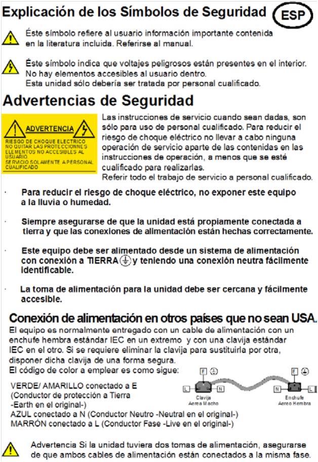
6 Safety Information Mains Power Supplies This equipment has two 3-pin IEC power sockets, one for the main power supply unit and one for the redundant power supply unit The power supply is auto switching for input voltages in the ranges of 100 V to 240 V nominal No voltage adjustment procedure is required This equipment has more than one power supply To reduce the risk of electric shock, plug each power supply into separate branch circuits employing separate service grounds Before performing any servicing or maintenance, disconnect and isolate the unit from the mains input and from any product outputs Do not operate this unit without an earth connection Power Cord Supplied The equipment is shipped with a power cord with a standard molded IEC female plug on one end and a standard mains plug on the other If you are required to remove the molded mains supply plug, dispose of the plug immediately in a safe manner The color code for the cord is as follows: GREEN/YELLOW lead connected to E (Protective Earth Conductor) BROWN lead connected to L (Live Conductor) BLUE lead connected to N (Neutral Conductor) Laser Safety EN (2001) Safety of Laser Products Caution: use of controls or adjustments or performance of procedures other than those specified herein may result in hazardous radiation exposure Viewing the laser diode with the optical fiber removed and with the aid of optical magnifiers may be hazardous This product is a Class 1 laser product (output power <15mW) at 1270 nm to 1610 nm with a beam divergence >30 mrad Ventilation Although the unit is constructed to meet normal environmental requirements, ensure that there is a free flow of air at the front, rear, and sides of the unit to dissipate the heat produced during operation Installations should be designed to allow for this Do not obstruct the ventilation holes on the right side of the unit Damage to the equipment may result Issue 1 Rev 1 Page SAM
 - UL File E193966 Standard for Safety Professional Video and Audio equipment EMC Standards This equipment conforms to the following standards: EN 55103-1: 1996")
 Electromagnetic Compatibility, Product family standard for audio, video, audio-visual and entertainment lighting control apparatus for professional use Part 2 Immunity FCC/CFR")
7 Safety Information Compliance Standards This equipment conforms to the following standards: EN : A11: 2009 Safety of Information Technology Equipment Including Electrical Business Equipment UL1419 (3rd Edition) - UL File E Standard for Safety Professional Video and Audio equipment EMC Standards This equipment conforms to the following standards: EN : 1996 (Environment E4) Electromagnetic Compatibility, Product family standard for audio, video, audio-visual and entertainment lighting control apparatus for professional use Part 1 Emission EN : 1996 (Environment E2) Electromagnetic Compatibility, Product family standard for audio, video, audio-visual and entertainment lighting control apparatus for professional use Part 2 Immunity FCC/CFR 47:Part 15, Class A Federal Communications Commission Rules Part 15, Subpart B, Class A EMC Environment The product(s) described in this manual conform to the EMC requirements for, and are intended for use in, the controlled EMC environment (for example, purpose-built broadcasting or recording studios), and the rural outdoor environment (far away from railways, transmitters, overhead power lines, etc) E4 EMC Performance of Cables and Connectors SAM products are designed to meet or exceed the requirements of the appropriate European EMC standards In order to achieve this performance in real installations it is essential to use cables and connectors with good EMC characteristics All signal connections (including remote control connections) shall be made with screened cables terminated in connectors having a metal shell The cable screen shall have a large-area contact with the metal shell Coaxial Cables Coaxial cables connections (particularly serial digital video connections) shall be made with high-quality double-screened coaxial cables such as Belden 1694 or BBC type PSF1/2M D-type Connectors D-type connectors shall have metal shells making good RF contact with the cable screen Connectors having dimples which improve the contact between the plug and socket shells are recommended Issue 1 Rev 1 Page SAM
8 Contents Information and Notices 2 Safety Information 3 1 Introduction Module Description Order Codes IQHCO IQHCO Rear Panel View IQHCO IQHCO Enclosures B-style Enclosure A-style Enclosures Feature Summary IQHCO IQHCO Technical Specification 17 3 Connections SDI I/O External Inputs/Outputs RJ45 SFP SDI SFP Connector Pinning Way D-Type Connection Pin-out for GPIOs on Double Width Rear Panel Pin Screw Terminal Connection for GPIOs on Single Width Rear Panel 21 4 Card Edge LEDs IQHCO50/51 Card Navigating Pages in the RollCall Template Template Pages Setting Values Information Display Selecting the Information to Display Information Display Summary Operation Mode Input 1/2 Select Inputs 3 and 4 Configuration Priority/Reversion Video Input Rules Valid Input State Rules Active State In Rules Selection Output Routing Input n Valid Input Status Valid Inputs Validity Timers Audio Pair Controls Outputs Routing 33 Issue 1 Rev 1 Page SAM
9 562 Legalizer RGB Legalizer Blanking Video ProcAmp Color Correction Enable White Stretch Mid Tones Black Stretch Test Pattern and Caption Generators Pattern Enable, Pattern Type H-Scroll Tone User Caption Animate Caption On Signal Loss GPIO 1-4, Ethernet Ethernet Domain Status SFP SFP Details SFP Inputs/Outputs Setup Restart Input Names Memories Savesets Saving a Saveset Restoring a Saveset RollTrack Disable All RollTrack Index Source Address RollTrack Command RollTrack Sending RollTrack Status Logging Logging Misc Logging Inputs Logging - Audio Inputs Logging - Output Logging - Changeover Rules Valid Input State Logging Rules GPIO State 61 Appendix A Active Formats & Signal Mapping 62 A1 Active Picture Areas 62 A2 Wide Screen Signaling and Aspect Ratio Control Overview 62 A3 Active Formats Illustrated 63 A4 Transformation Descriptions 64 A5 Mapping of External Signaling to Internal States 65 A6 4:3 Target Aspect Default Mapping 66 A7 16:9 Target Aspect Default Mapping 67 A8 Products Featuring RollTrack 68 A9 Configuration: Single Video Unit and Single Audio Delay 68 A10 Configuration: Multiple Video Units and Audio Delays 68 Issue 1 Rev 1 Page SAM
10 A11 Configuration: Vertical Delay Cluster 69 A12 Configuration: Horizontal Delay Cluster 69 A13 Configuration: Matrix Delay Cluster 70 A131 Configuration: An Array of Matrix Clusters 72 Issue 1 Rev 1 Page SAM
11 Introduction 1 Introduction 11 Module Description The IQHCO50/51 provides backup protection for SDI signal paths Inputs are monitored for signal errors; when an error state is recognized, a backup feed is automatically switched to A powerful rules engine is available to provide logical conditions for auto-switching, whilst GPIO or RollTrack inputs can force the unit to switch independently of signal state The IQHCO51 model also includes a synchronizer 12 Order Codes Note: Modules with A order codes (for example, IUDC0000-2A) can be fitted into either A- or B-style enclosures Modules with B order codes (for example, IQUDC0000-2B) can only be fitted into B-style enclosures See page 14 The following product order codes are covered by this manual: 121 IQHCO50 IQHCO5000-1B3 IQHCO5001-1A3 IQHCO5001-1B3 IQHCO5002-2A3 IQHCO5002-2B3 3G/HD/SD-SDI Signal Protection Module, 3 SDI In, 2 SDI Out, 2 SDI Monitor outputs, 2 GPIO 3G/HD/SD-SDI Signal Protection Module, 3 SDI In, 1 SDI Out, 1 SDI Monitor outputs, Relay bypass, 2 GPIO 3G/HD/SD-SDI Signal Protection Module, 3 SDI In, 2 SDI Out, 1 SDI Monitor outputs, Latching Relay bypass, 8 GPIO Issue 1 Rev 1 Page SAM

12 Introduction IQHCO5003-2A3 IQHCO5003-2B3 TBD 3G/HD/SD-SDI Signal Protection Module, 3 SDI In, 2 SDI Out, 1 SDI Monitor outputs, 8 GPIO, SFP SDI, Ethernet Color Corrector option 122 IQHCO51 IQHCO5100-1A3 IQHCO5100-1B3 IQHCO5101-1A3 IQHCO5101-1B3 IQHCO5102-2A3 IQHCO5102-2B3 IQHCO5103-2A3 IQHCO5103-2B3 3G/HD/SD-SDI Signal Protection Module, 3 SDI In, 2 SDI Out, 1 SDI Monitor outputs, 2 GPIO, 1 Reference In 3G/HD/SD-SDI Signal Protection Module, 3 SDI In, 1 SDI Out, 1 SDI Monitor outputs, Relay bypass, 2 GPIO, 1 Reference In 3G/HD/SD-SDI Signal Protection Module, 3 SDI In, 2 SDI Out, 1 SDI Monitor outputs, Latching Relay bypass, 8 GPIO, 1 Reference In 3G/HD/SD-SDI Signal Protection Module, 3 SDI In, 2 SDI Out, 1 SDI Monitor outputs, 8 GPIO, SFP SDI, Ethernet, 1 Reference In 13 Rear Panel View 131 IQHCO50 IQHCO5000-1A3, IQHCO5000-1B3 IQHCO5001-1A3, IQHCO5001-1B3 IQHCO5002-2A3, IQHCO5002-2B3 Issue 1 Rev 1 Page SAM


13 Introduction IQHCO5003-2A3, IQHCO5003-2B3 132 IQHCO51 IQHCO5100 IQHCO5101-1A3, IQHCO5101-1B3 IQHCO5102-1A3, IQHCO5102-1B3 IQHCO5103-2A3, IQHCO5103-2B3 Issue 1 Rev 1 Page SAM


14 Introduction 14 Enclosures The IQHCO50/51 modules can be fitted into the enclosure types shown Important: Although IQ modules are interchangeable between enclosures, their rear panels are enclosure specific An IQH3B enclosure accepts modules with either A or B order codes An IQH3A or IQH1A enclosure accepts modules with A order codes only See page B-style Enclosure Enclosure order codes: IQH3B-S-0, IQH3B-S-P 142 A-style Enclosures Enclosure order code: IQH1A-S-P Enclosure order codes: IQH3A-S-0, IQH3A-S-P Enclosure order codes: IQH3A-E-0, IQH3A-E-P, IQH3A-0-0, IQH3A-0-P Issue 1 Rev 1 Page SAM
15 Introduction 15 Feature Summary 151 IQHCO Options 3Gbps SDI, HD-SDI and SD-SDI operation with RGB legalization Auto changeover from either input on pre-defined error conditions User-definable changeover delay Connectivity: 3 SDI inputs, up to 4 SDI outputs (2 main and 2 monitoring), up to 8 x GPI/O, relay bypass versions with input 1 bypassed to output 1 on power loss or card removal, or selected input bypassed to output 1 on power loss or card removal Input signal monitoring including SDI lock, ASI carrier detection, EDH/CRC error, Freeze detection, Black detection, embedded audio loss and standard mismatch Up to 32 channel embedded audio support Card Edge Control for input switch & LED status indicators Selectable SDI monitoring outputs enable either input to be monitored independent of the main signal selection In-built test pattern generator and embedded audio tone generator 16 x user memories, save/recall/rename Input signal relay bypass versions available (options for either basic input 1 to output 1, or follow input select bypass) RollCall monitoring allows all signal paths to be managed Single mode fiber optic transmitter and receiver options Color corrector 152 IQHCO51 3G/HD/SD-SDI operation with synchronizer and additional video delay up to 4 frames and RGB legalization Auto change-over from any input on pre-defined error conditions User definable change-over delay Connectivity: 3 SDI inputs, up to 4 SDI outputs (2 main and 2 monitoring), reference input, up to 8 x GPI/O, Ethernet I/O, relay bypass versions with input 1 bypassed to output 1 on power loss or card removal, or selected input bypassed to output 1 on power loss or card removal Input signal monitoring including SDI lock, ASI carrier detection, EDH/CRC error, Freeze detection, Black detection, embedded audio loss and standard mismatch Reference input capable of detecting and referencing to a bi-level or tri-level signal and selection from either external input directly or from internal IQH3B chassis reference bus Agile, router switching tolerant synchronizer operation with genlock adjustment allowing you to time any SDI signal to pixel accuracy with greater tolerance to mis-timed upstream SDI switching (up to +/- 10 lines), ensuring disturbance-free picture output Up to 32-channel embedded audio support Audio proc amp features including channel level (Sub-frame) routing, independent gain, invert and mute control with audio V Fade on switch over Card Edge Control for input switch & LED status indicators Issue 1 Rev 1 Page SAM
16 Introduction 1521 Options Selectable SDI monitoring outputs enable either input to be monitored independent of the main signal selection In-built test pattern generator and embedded audio tone generator 16 x user memories, save/recall/rename Input signal relay bypass versions available (options for either basic input 1 to output 1, or follow input select bypass) RollCall monitoring allows all signal paths to be managed Single mode fiber optic transmitter and receiver options Color corrector SAM audio loudness monitoring Media Biometrics Signature Logo insertion IP thumbnailing Issue 1 Rev 1 Page SAM
17 Technical Specification 2 Technical Specification Inputs and Outputs Signal Inputs Inputs 3 Connector/Format BNC/75R Conforms to 3G-SDI to SMPTE 424M/425M level A/B compatible HD-SDI to SMPTE292M/274M/296M SD-SDI to SMPTE259M-C Input Cable Length Inputs Up to 92m Belden 3 Gbit/s Up to 156m Belden 15 Gbit/s Up to >375m Belden 270 Mbit/s Input 3 Up to 80m Belden 3 Gbit/s Up to 140m Belden 15 Gbit/s Up to >375m Belden 270 Mbit/s Signal Outputs Outputs Up to 2 Monitors Up to 2 Connector/Format BNC/75R Conforms to 3G-SDI to SMPTE 424M/425M level A/B compatible HD-SDI to SMPTE292M/274M/296M SD-SDI to SMPTE259M-C Connector/Format SFP Conforms to 3G-SDI to SMPTE 424M/425M level A/B compatible HD-SDI to SMPTE292M/274M/296M SD-SDI to SMPTE259M-C Video Standards Control Interface GPIO 2-8 Electrical TTL compatible, active low driven Connector/Format Indicators Power CPU 1-12 Input Standard Detection LEDs Standard SAM screw terminal/d-type Front Panel & Card Edge OK (Green) OK (Green flashing) Lock (Green) None (Red) Issue 1 Rev 1 Page SAM
18 Technical Specification RollCall Features Status User Memories Logging RollTrack Controls Setup Specifications Electrical Connector/Format Power Consumption Module power consumption Input and Output None Input status Input alarms Output status Output alarms Misc On/off, Index, Source, Address, Command, Status, Sending Versions, reset defaults, restart ASI transport stream BNC/Standard SAM screw terminal 11PR (115W) Issue 1 Rev 1 Page SAM


19 Connections 3 Connections This section describes the physical input and output connections provided by the IQHCO50/51 31 SDI I/O 12 x 3G/HD/SD-SDI interfaces provided with HD-BNC 32 External Inputs/Outputs Two general purpose GPIO are provided using standard screw terminals 33 RJ45 SFP RJ45 10/100/1G Ethernet 34 SDI SFP SFP supporting 3G/HD/SD-SDI Issue 1 Rev 1 Page SAM

20 Connections 35 Connector Pinning Way D-Type Connection Pin-out for GPIOs on Double Width Rear Panel Pin No Pin No Name Description 1 GPIO_4 General Purpose Interface 4 14 GPIO_0 General Purpose Interface 0 2 GPIO_5 General Purpose Interface 5 15 GPIO_1 General Purpose Interface 1 3 GPIO_6 General Purpose Interface 6 16 GPIO_2 General Purpose Interface 2 4 GND Ground 17 GND Ground 5 GPIO_7 General Purpose Interface 7 18 GPIO_3 General Purpose Interface 3 6 N/A Not Used 19 N/A Not Used 7 GND Ground 20 GND Ground 8 N/A Not Used 21 N/A Not Used 9 N/A Not Used 22 N/A Not Used 10 GND Ground 23 GND Ground 11 META_p Not Used 24 META_n Not Used 12 LTC_p Not Used 25 LTC_n Not Used 13 GND Ground Issue 1 Rev 1 Page SAM
21 Connections Pin Screw Terminal Connection for GPIOs on Single Width Rear Panel Pin No Name Description 1 GPIO_1 General Purpose Interface 1 2 GND Ground 3 GPIO_2 General Purpose Interface 2 Issue 1 Rev 1 Page SAM
22 Card Edge LEDs 4 Card Edge LEDs 41 IQHCO50/51 Card The LEDs on the edge of the IQHCO50/51 card indicate its operating status LED Color State Description Local Control Yellow Illuminated Module is being controlled via the on-board hardware switches, not remotely via RollCall Use the toggle switch to select Local or Remote mode Input 1-3 Green Illuminated Input has been selected and a valid input is present Power Green Illuminated Good power supply is present FPGA OK Green Illuminated FPGA has been correctly programmed CPU OK Green Flashing CPU is running ERROR Red Illuminated Board fault conditions LED is illuminated in the event of: Primary input fail License error FPGA comms failure FPGA upgrading FPGA overheat FPGA demo reboot reminder 5 mins, 3 mins, 60 secs WARN Yellow Illuminated Board warning conditions LED is Illuminated in the event of: CRC errors License minor faults Video pattern, freeze, black or caption Audio routing mismatch (data/pcm mixed) Configured reference not valid FPGA overheat warning OK Green Illuminated Module is operating correctly Issue 1 Rev 1 Page SAM

23 5 This section contains information on using the IQHCO50/51 with RollCall For help with general use of the RollCall application, open the user manual by clicking the button on the main RollCall toolbar 51 Navigating Pages in the RollCall Template The RollCall template has a number of pages, each of which can be selected from the list at the top left of the display area Right-clicking anywhere on the pages will also open a page view list, allowing quick access to any of the pages Page List 511 Template Pages The following pages are available: Summary - see section 54 Input n Valid - see section 55 Outputs - see section 56 Video ProcAmp - see section 57 Color Correction - see section 58 Caption and Test Pattern Generators - see section 59 GPIO 1-4, see section 510 Ethernet - see section 511 SFP - see section 512 Setup - see section 513 Memories - see section 514 Savesets - see section 515 RollTrack - see section 516 Logging - see section 517 Logging Output - see section 518 Logging - Changeover - see section 519 Issue 1 Rev 1 Page SAM


24 512 Setting Values Many of the settings within the templates have values, either alpha or numeric When setting a value in a field, the value, whether text or a number, must be set by pressing the ENTER key, or clicking the Save Value button Clicking an associated Preset Value button returns the value to the factory default setting 52 Information Display The Information display pane appears at the top of each page, and shows basic information on the input, standard and status of the module The information to be displayed is defined on the SDI Selection and Information Select panes to the right of the Information display 521 Selecting the Information to Display Select the spigots to display data for from the SDI Selection drop-down list Select Video Input Status, Video Output Status or Network Status from the Information Select pane as required The selected information will be displayed on the Information display pane enables you to control IQ modules through various different pages See the RollCall Control Panel Installation & Operator s Manual for information about installation and setup of the RollCall Control Panel Note: The content and order of the pages shown in this section are for guidance and reference only, and may be slightly different to what you see with your module The look and functions may also differ slightly from other modules in the range 53 Information Display The Information display pane appears at the top of each page, and shows basic information on the status of the module The information to be displayed is selected on the Information Select pane to the right of the Information display Issue 1 Rev 1 Page SAM

25 54 Summary The Summary page provides a general overview of the module The following facilities are provided: 541 Operation Mode Select ASI to enable ASI passthrough Note: The rules engine is applied to 3G/HD/SD SDI mode only It is bypassed when the ASI passthrough is enabled 542 Input 1/2 Select Select whether the input is SDI or via SFP 543 Inputs 3 and 4 Configuration Input 3 Failsafe Active - Un-check to disable Input 3 Failsafe Input 4 TPG Active - Un-check to disable Input 4 TPG 5431 Input 4 TPG Mode Select whether the TPG input is to be persistent or not Issue 1 Rev 1 Page SAM

26 544 Priority/Reversion 5441 Flow Priority Allows the way in which the module behaves when an input fails to be defined The following options are available: None - If the current input fails, the output fails over to the next available input in the following order: a Input 1 Primary b Input 2 Secondary c Input 3 Failsafe d TPG It will not roll back if a failing channel recovers Input 1 Primary Priority - If Input 1 recovers having previously failed, the output reverts to Input 1 Input 2 Secondary Priority - If Input 2 recovers having previously failed, the output reverts to Input 2 Input 3 Failsafe Priority - If selected, Input 3 is used If not, the dedicated TPG on input 4 is used 5442 Reversion Delay The reversion delay sets the amount of time for which a condition must be True before reverting to the next condition Set the slider as required 545 Video Input 5451 Input State Displays state of the video inputs Issue 1 Rev 1 Page SAM


27 546 Rules Valid Input State This pane reports the current input state 547 Rules Active State The Rules Active Status pane reports the status of the rules engine 548 In Rules Selection This pane allows a particular input to be specified as a default to be used by the rules engine, if there are no other rule-induced changes Select as required 549 Output Routing 5491 Output Routing in Remote Mode This pane is used to select the output for main and monitor Select as required Issue 1 Rev 1 Page SAM


28 5492 Output State This pane reports the current output state 5493 Output Routing in Local Mode This pane allows the main output to be selected locally, and defines whether the monitor output should follow the main Select as required Issue 1 Rev 1 Page SAM

29 55 Input n Valid There are three input valid pages, one for each for input These controls all relate to the validity checks applied to the input and then subsequently used by the rules engine They are grouped into video and audio Issue 1 Rev 1 Page SAM


30 551 Input Status For each of the inputs, the current rules state is reported, along with the rules state of the given input Additional controls are provided to allow for copying of settings to the other two pages 552 Valid Inputs The Input Status pane is a mirror of the information reported on the summary page The Valid Input Standards check boxes allows the user to select the standards to be used for validity checking If a standard presented to the rules engine is selected, it passes; if not, it causes an error Note: ASI is unprocessed ASI is passed directly through the card if the ASI carrier check box is enabled 553 Validity Timers Validity timers generally behave in the same way For clarity, only the Carrier Detect section has been detailed below and where there are exceptions/additions to these controls 5531 Carrier Detect If the carrier is missing for the period of time defined by the fail timer, a fail is reported The error condition has to be absent for the period defined by the recovery timer for the condition to be removed For must controls an enable check box is provided 5532 Valid CRC/EDH In addition to the Fail and Recovery Timer's resets are provided for the error counts 5533 Black Detector A Black threshold is provided at which the rule is applied Issue 1 Rev 1 Page SAM

31 In addition to the above, the following validity timers are provided: Freeze Detector Audio Monitor Levels Audio Timers 554 Audio Pair Controls For each of the audio pairs the following controls are available to the rules engine The top four panes report the current audio type and the pair state The following types are supported: PCM DolbyE Data Any None Ignored The following check boxes allow the rules engine to be applied to the named audio characteristic, based on the values of the previous controls Mute Low level Overload Issue 1 Rev 1 Page SAM

32 56 Outputs A single Outputs page covers both main and monitor Issue 1 Rev 1 Page SAM


33 561 Routing The output routing pane provides monitoring and control of the output This same information is mirrored on the Summary page 562 Legalizer Both outputs are legalized for both RGB and Luma Issue 1 Rev 1 Page SAM
34 563 RGB Legalizer Illegal colors are represented by values of RGB that are outside a nominal range, typically 0-700mV, when converted to analog values Illegal RGB colors are easily generated in YCbCr space because of the differences in the valid color space between RGB and YCbCr Upon detection of illegal RGB colors, there are a variety of techniques to bring them back into legal color space Most legalizers will simply de-saturate the chrominance, leaving the luminance unaltered The legalizer used by SAM is more advanced, and is able to preserve the original saturation to a much greater extent by modifying the luminance and chrominance signals simultaneously, giving the best visually subjective results Off 5631 Luma Clipper 700mV: 0mV to 700mV 721mV: -21mV to 721mV 735mV: -35mV to 735mV 746mV: -46mV to 746mV These controls can be used to limit the luminance of the signal at the output Advanced White Knee and Black Knee controls are available to soften the clipper, giving a gradual transition to the limit By default the clipper is disabled When Input Format is set to 4:4:4 RGB, clipping is applied to R, G and B channels White Max: This sets up the upper limit (hard clip point) of the clipper The range is minimum 60% (590 digital 10-bit value) to maximum 109% (1019) with increments of 1% The default is 103% (966) White Knee: This sets up the knee for the maximum white limit of the clipper This can be set up to give a "soft clip" from this knee point to the hard white clip point The range is minimum 60% (590) to maximum 109% (1019) with increments of 1% The default is 100% (940) Black Knee: This sets up the knee for the minimum black limit of the clipper This can be set up to give a "soft clip" from this knee point to the hard black clip point The range is minimum -7% (4) to maximum 60% (590) with increments of 1% The default is 0% (64) Black Min: This sets up the lower limit (hard clip point) of the clipper The range is minimum -7% (4) to maximum 60% (590) with increments of 1% The default is -1% (55) Issue 1 Rev 1 Page SAM
35 To achieve a hard white clip, set White Max and White Knee to the same value Similarly, to achieve a hard black clip set Black Min and Black Knee to the same value The luma clipper can be used in combination with the 735mV legalizer selection to generate images which adhere to the EBU R specification 564 Blanking Data is passed but can be blanked for V and H independently for both outputs VANC Standard Lines Blanked , , i 8-20, p 8-41 Issue 1 Rev 1 Page SAM
:")
36 57 Video ProcAmp Each input has a ProcAmp The ProcAmp allows the following to be adjusted: ProcAmp Enable: Select this check box to enable the ProcAmp functions Clear the check box to disable and bypass the ProcAmp functions Black Level: The Black Level control allows the channel's black level to be adjusted over a range of ±100 mv in steps of 08 mv The preset value is 0 Cb/Cr Gain (Chroma): The Cb/Cr Gain control allows the chrominance to be adjusted over a range of ±6 db in steps of 01 db The preset value is 0 Hue Adjust: The Hue control allows the channel's hue to be adjusted over a range of ±180 in steps of 1 The preset value is 0 Y/C Timing: The Y/C Timing control allows the luma/chroma timing to be adjusted over a range of: ± 8 pixels in 2 pixel steps in SD ± 16 pixels in 2 pixel steps in HD/3G The preset value is 0 Master Video Gain: The Mater Video Gain control allows the video gain to be adjusted over a range of ±6 db in steps of 01 db The preset value is 0 Issue 1 Rev 1 Page SAM
37 Picture Position: The Picture Position control allows the picture position to be adjusted over a range of: ± 8 pixels in 2 pixel steps SD ± 16 pixels in 2 pixel steps HD/3G The preset value is 0 Y Gain Luma: The Y Gain control allows the luma to be adjusted over a range of ±6 db in steps of 01 db The preset is 0 Issue 1 Rev 1 Page SAM


38 58 Color Correction Each input has a color corrector Each color corrector has the following controls: Enable White Stretch Mid Tones Black Stretch Master Knee 581 Enable Check the Enable check box to activate color correction for the associated input 582 White Stretch White Stretch is used to lift or crush whites Issue 1 Rev 1 Page SAM
39 The M (Master) slider affects the luma content of the picture, and the RGB controls are used to adjust the balance of the red, green and blue channels All controls apply irrespective of the Input Format setting With the addition of the Upper Knee control, it is possible to adjust whites only, leaving blacks unchanged a White stretch b Normal c White crush 583 Mid Tones The Mid Stretch control can be used to adjust the gamma With the addition of the Mid Hi Knee and the Mid Lo Knee controls, the location of the stretch/crush can be finely tuned to blacks, whites or the midpoint a Mid stretch b Normal c Mid crush Issue 1 Rev 1 Page SAM
40 584 Black Stretch Black Stretch can be used to lift or crush blacks With the addition of the Lower Knee control, it is possible to adjust blacks only, leaving whites unchanged a Black stretch b Normal c Black crush Issue 1 Rev 1 Page SAM

41 59 Test Pattern and Caption Generators Each of the three inputs has its own test pattern and caption generator There is also a fourth dedicated test pattern and caption generator Each color corrector has the following controls: Pattern Enable H-Scroll Pattern Type Tone Enable, frequency and channel ident Caption, alternate text, animation, position and size On input loss 591 Pattern Enable, Pattern Type To enable a test pattern, select an item from the Pattern Type list and then check the Enable check box 592 H-Scroll 593 Tone Enable H-Scroll to scroll the pattern horizontally This control allows the tone and its frequency to be enabled and adjusted 594 User Caption These controls allow caption text, alternate text, its size and position to be adjusted Issue 1 Rev 1 Page SAM
42 595 Animate Caption When enabled, a caption will appear as white text on a black background in the lower portion of the picture Basic animation may also be selected, which enables a scrolling effect from right to left, also known as a 'ticker-tape' effect The options are: Animate Off Animate Slow Animate Medium Animate Fast 596 On Signal Loss In the event of signal loss, a default behavior for the pattern generator can be set here Click Enable to activate, then select the appropriate display from the list Note: It is important to appreciate that enabling this mode of operation can effectively mask the fact that the input has been lost, and may not necessarily cause the rules engine to be triggered Issue 1 Rev 1 Page SAM


43 510 GPIO 1-4, 5-8 This page provides configuration and action control for the General Purpose IO Up to 8 IO ports can be supported Each port has an associated GPIO pane: Controls provided are: Direction: Allows the interface to be configured as an input or an output Select one, and then select behaviors as required: Issue 1 Rev 1 Page SAM
44 GPI input high behavior: Select a behavior to use if the interface has been configured as an input and is transitioning low to high GPI input low behavior: Select a behavior to use if the interface has been configured as an input and is transitioning high to low GPO output trigger: If configured as an output, the selected event causes the output to be asserted Invert Output: Enable the check box to invert the output if required Issue 1 Rev 1 Page SAM


45 511 Ethernet The Ethernet page provides controls for the RJ45 interface 5111 Ethernet The Ethernet pane allows the setting of static IP properties or DHCP New settings are applied only once Take is pressed The MAC address is read-only Issue 1 Rev 1 Page SAM


46 5112 Domain RollCall+ uses Domains to partition a network Only those nodes on the same domain can communicate with one another A domain is uniquely identified with number and a friendly name/alias 5113 Status The status pane provides information about the network status such as packets sent, dropped Issue 1 Rev 1 Page SAM

47 512 SFP The SFP page allows SFPs to be configured, and various parameters to be monitored 5121 SFP Details Displays basic SFP details Configure Types Allows Transmit/Receive and Connection Media types to be specified Select a radio button for each type as required 5122 SFP Inputs/Outputs Displays various parameters, and allows output from SFPs to be switched off Also allows output to be switched off automatically if an input error is detected Select check boxes as required Issue 1 Rev 1 Page SAM

48 513 Setup The Setup page displays basic details of the module You may be asked for these if you contact SAM technical support 5131 Restart Power-cycles the module, and allows the module to be reset to default settings Option Default Settings Factory Defaults Operation All controls are reset to their default values, except for network configuration and IP addresses All controls are reset to their default values, including network configuration and IP addresses 5132 Input Names Inputs may be renamed if required To do this, overwrite the default, and click the Save Value button To discard an entry and return to the default value, click the Preset Value button Issue 1 Rev 1 Page SAM


49 514 Memories The Memory page enables up to 16 setups to be saved and recalled later Default memory names can be changed to provide more meaningful descriptions 515 Savesets Savesets allow the user to save predetermined RollControl product field settings to file, which can then be used to either transfer the settings to another card, or used as a backup of the settings for that card The Saveset feature is available via the RollCall Control Panel client 5151 Saving a Saveset This is performed from the RollCall Control Panel Connected Units pane: 1 Click to display the Backup dialog: 2 Click Save to save to the default folder, or Save To to save to a specified folder Issue 1 Rev 1 Page SAM

50 5152 Restoring a Saveset 1 From the Connected Units pane, select the icon; the Restore dialog is displayed: Click Restore to restore from the default folder, or Restore From to restore from a specified folder Issue 1 Rev 1 Page SAM

51 516 RollTrack The RollTrack page allows information to be sent via the RollCall network to other compatible units connected on the same network 5161 Disable All When checked, all RollTrack items are disabled 5162 RollTrack Index This slider enables up to 16 RollTrack outputs to be set up Dragging the slider selects the RollTrack Index number, displayed below the slider Clicking P selects the default preset value 5163 Source Select the source of information to trigger the transmission of data Clicking P selects the default preset value When no source is selected, Unused is displayed 5164 Address This is where the address of the selected destination unit is set Type a destination into the text area, then click S to save the selection Clicking P will return to the default preset destination A RollTrack address consists of four sets of numbers; for example, 0000:10:01*99: The first set (0000) is the network segment code number The second set (10) is the number identifying the (enclosure/mainframe) unit The third set (01) is the slot number in the unit The fourth set (99) is a user-definable number that is a unique ID for the destination unit in a multi-unit system This ensures that only the correct unit will respond to the command If left at 00, an incorrectly fitted unit may respond inappropriately Issue 1 Rev 1 Page SAM
52 5165 RollTrack Command This enables a command to be sent to the selected destination unit The command may be changed by typing a code in the text area and then selecting S to save the selection Clicking P returns to the default preset command The RollTrack command consists of two sets of numbers, for example: 84:156: The first number (84) is the actual RollTrack command The second number (156) is the value sent with the RollTrack command 5166 RollTrack Sending Indicates when a RollTrack is being sent Displays either Yes or No 5167 RollTrack Status A message is displayed here to indicate the status of the currently selected RollTrack index Possible RollTrack Status messages are: Message OK Unknown Timeout Bad Disabled Description RollTrack message sent and received OK RollTrack message has been sent but it has not yet completed RollTrack message sent but acknowledgement not received This could be because the destination unit is not at the location specified RollTrack message has not been correctly acknowledged at the destination unit This could be because the destination unit is not of the type specified RollTrack sending is disabled Issue 1 Rev 1 Page SAM

53 517 Logging Information about several parameters can be made available to a logging device that is connected to the RollCall network Each logging page comprises three columns: Log Enable - Enable the check box for each parameter to be logged Log Field - Displays the name of the logging field Log Value - Displays the current log value 5171 Logging Misc The Logging Misc page allows information on the module s basic parameters to be logged Enable check boxes as required Log Field SN= OS_VERSION= BUILD_NUMBER= HARDWARE_VERSION = Description Reports the module serial number, which consists of an S followed by eight digits Note - this cannot be deselected Reports the operating system name and version For example, KOS V115 Reports the build number Reports the hardware version number HARDWARE_MOD= Reports the hardware modification level FIRMWARE_VERSION= Reports the ASI controller firmware version Issue 1 Rev 1 Page SAM
54 Log Field TEMP_1_STATE= TEMP_1_NAME= UPTIME= ROL_STATES= LAST_RECALLED_ MEMORY= Description Reports temperature sensor state Possible values are: WARN: Disabled - Temperature sensor disabled WARN: Low - Low, but in tolerance WARN: High - High, but in tolerance OK FAIL: Low - Low and out of tolerance FAIL: High - High and out of tolerance Reports temperature sensor name Reports the time since the last restart in the format ddd:hh:mm:ss Reports RollTrack status Possible values are: OK Disabled FAIL Reports last memory to be recalled REAR_ID= Reports the rear panel type number REAR_STATUS= Reports the status of the rear panel SLOT_WIDTH= Reports the slot width SLOT_START= Reports the slot start number POWER_USAGE= Reports the power rating for the module Note this is not a live power reading, but rather a maximum rating LICENSED_OPTIONS= Reports licenses installed IPADDRESS= Reports current IP address LAN_PORT_1_STATE= Reports Ethernet connection state LAN_PORT_1_SPEED= Reports Ethernet connection speed LAN_PORT_1_NAME= Reports Ethernet port name as defined by the OS Issue 1 Rev 1 Page SAM

55 5172 Logging Inputs The Logging Inputs page is used to select the fields to be enabled for logging each of the four inputs Issue 1 Rev 1 Page SAM
56 Log Field INPUT_N_STATE= Description Possible values are: OK: input signal good FAIL: input signal not detected INPUT_N_STANDARD PAL/NTSC/625 Mono/525 Mono = INPUT_N_SDI_ERRS= SDI errors that have occurred in a one-second period Possible values are: OK WARN INPUT_N_TYPE= Type of input as specified by the module s configuration Range 1 3 Possible values are: 3G/HD/SD SDI HD/SD SDI HD/SD Analog SD Analog INPUT_N_IDENT= Identifier string on the rear interface Possible values are: Y/C:YPbPr:COMP In COMP In SERIAL IN SERIAL IN 1 SERIAL IN 2 INPUT_N_BLACK_ Reports Black errors Possible values are: ERRS= OK FAIL INPUT_N_FREEZE_ Reports Freeze errors Possible values are: ERRS= OK FAIL INPUT_N_CAPTION= Reports caption state Possible values are: OK WARN INPUT_N_PATTERN= Possible values are: 100% Color Bars SMPTE Bars Tartan Bars Pluge Ramp Sweep Pulse & Bar Burst Black Where N is the input number Issue 1 Rev 1 Page SAM

57 5173 Logging - Audio Inputs 1-3 The Logging Audio Input page is used to select the fields to be enabled for logging audio inputs Issue 1 Rev 1 Page SAM
58 Log Field INPUT_N_AUDIO_ ALARM_PAIR_X_ STATE= INPUT_N_EMBEDDED_ AUDIO_X_STATE= Description Reports alarm conditions for the selected pair/channel Possible values are: OK FAIL Reports information on incoming embedded audio Possible values are: OK:PCM - PCM present OK:Data - Non-PCM AES audio present OK:Dolby E - Dolby E audio present FAIL:LOST - Audio not present WARN:Unknown - Unselected SDI input with unknown embedded audio state Where N is the input number and X is the audio pair/channel number Issue 1 Rev 1 Page SAM

59 518 Logging - Output The Logging Output page is used to select the fields to be enabled for logging outputs Log Field OUTPUT_N_TYPE= OUTPUT_N_STATE= OUTPUT_N_ STANDARD= OUTPUT_N= Description Logs output type Possible values are: SD SDI HD SDI HD/SD/3G SDI Logs state of the output Possible values are: OK FAIL WARN: Freeze WARN: Pattern Logs details of the output standard in this format: <Lines>(<Active>)/<Rate><i/p/sf> Where: Lines = Total lines Active = Active lines Rate = Frame rate I = Interlaced P = Progressive SF = Slow Frame Rate Logs output source Taken from editable name of selected input Issue 1 Rev 1 Page SAM

60 Log Field OUTPUT_N_CAPTION OUTPUT_N_PATTERN Description Logs caption information Possible values are: OK - Off WARN - On Logs test pattern information Possible values are: 100% Color bars SMPTE bars Tartan bars Pluge Ramp Sweep Pulse & bar Burst Black Where N is the input number 519 Logging - Changeover The Logging-Changeover page allows errors or events which cause a failover to be logged 5191 Rules Valid Input State Select check boxes to activate logging to a downstream device attached to the RollCall network Issue 1 Rev 1 Page SAM
61 5192 Logging Rules Select the check box to activate logging of any event generated by the rules engine to a downstream device attached to the RollCall network 5193 GPIO State Select check boxes to activate logging of GPIO states to a downstream device attached to the RollCall network Note: All log values will be shown on-screen regardless of the settings made here Issue 1 Rev 1 Page SAM
62 Active Formats & Signal Mapping Appendix A Active Formats & Signal Mapping A1 Active Picture Areas The active picture areas used in the wide screen signaling scheme for aspect ratio control are described here for reference A basic principle of operation is that any picture can be processed from the following information: The whole picture aspect ratio (ie the target or coded screen) The active area used within the screen (outside is generally left black to create a letterbox in either orientation) How much of the active area is to be preserved (optional shoot-and-protect area indicated in the table by the circles) Where within the screen the active area is (optional top attribute used for extended subtitle area) Knowing this and the output aspect ratio for conversion to, it is possible to do a mapping which will correct the aspect ratio while preserving the active picture and minimizing black bar area A2 Wide Screen Signaling and Aspect Ratio Control Overview The Input signal drivers decodes and defaults selected signaling to give a valid Aspect Ratio (strictly 4:3 or 16:9) and Active Format Descriptor (AFD) (8 ARDSPEC1 entries, plus 3 extended and unknown pair) If no input signal or data is present, the aspect ratio & AFD will be 4:3 - Unknown These two signals are sent to the aspect mapping table (see below), which is initialized by a full set of defaults This uses Aspect and AFD pair (24 values) to call up fixed and programmable Display memories Display memory functions include Size, Aspect, Tilt, Pan and Input Crop Left / Right / Top / Bottom Issue 1 Rev 1 Page SAM

63 Active Formats & Signal Mapping A3 Active Formats Illustrated Issue 1 Rev 1 Page SAM
64 Active Formats & Signal Mapping A4 Transformation Descriptions These are the Standard Presets for Display Memories and are also copied into the first 9 user Display Memories They are heavily used by the wide screen signaling based automatic Aspect Ratio Control functionality as the core transformations Transformation naming terminology (also default memory name) is: (source aspect for ambiguous 14:9) (box when present) source AFD > (box) target display aspect Issue 1 Rev 1 Page SAM
65 Active Formats & Signal Mapping A5 Mapping of External Signaling to Internal States Signaling supports WSS ETSI (Line 23), Video Index (SMPTE RP186), and the ARD Spec versions of both these interface formats These are all translated into an internal Aspect Ratio and ETSI AFD format for use in the mapping tables and error handling to allow a consistent view This table shows how WSS ETSI (Line 23) is mapped into the internal format Where a resulting conversion cannot be turned back into an ETSI signal the WSS output will be disabled ARD Spec formats directly map onto the unshaded formats Both Video Index SMPTE and the ARD Spec variants provide for unknown active formats so a valid output signal can always be maintained Note that ARD Spec codes are 0 to 7 rather than the AFD range of 8 upwards Code (12) Reserved is supported in case customized legacy schemes make use of it WSS ETSI Coded Aspect In Internal Coded Aspect & Active Format (AFD) WSS ETSI Coded Aspect Out - 4:3 & Unknown (0) Full format 4:3-16:9 & Unknown (7) Full format 16:9 (4) Box 16:9 top 4:3 & (2) Box 16:9 top (4) Box 16:9 top - 16:9 & (2) Box 16:9 top No signal (2) Box 14:9 top 4:3 & (3) Box 14:9 top (2) Box 14:9 top - 16:9 & (3) Box 14:9 top No signal (5) Box > 16:9 centre 4:3 & (4) Box >16:9 centre (5) Box > 16:9 centre - 16:9 & (4) Box >16:9 centre No signal (0) Full format 4:3 4:3 & (8) As coded frame (0) Full format 4:3 (7) Full format 16:9 16:9 & (8) As coded frame (7) Full format 16:9-4:3 & (9) 4:3 centre (0) Full format 4:3-16:9 & (9) 4:3 centre No signal (3) Box 16:9 centre 4:3 & (10) 16:9 centre (3) Box 16:9 centre - 16:9 & (10) 16:9 centre (7) Full format 16:9 (1) Box 14:9 centre 4:3 & (11) 14:9 centre (1) Box 14:9 centre - 16:9 & (11) 14:9 centre No signal - 4:3 & (12) Reserved No signal - 16:9 & (12) Reserved No signal (6) Full 4:3 shoot-andprotect 14:9 centre 4:3 & (13) 4:3 shoot-and-protect 14:9 centre (6) Full 4:3 shoot-and- protect 14:9 centre - 16:9 & (13) 4:3 shoot-and-protect 14:9 centre No signal - 4:3 & (14) 16:9 shoot-and-protect 14:9 centre No signal - 16:9 & (14) 16:9 shoot-and-protect 14:9 centre No signal - 4:3 & (15) 16:9 shoot-and-protect 4:3 centre No signal - 16:9 & (15) 16:9 shoot-and-protect 4:3 centre No signal Numbers in brackets in this column indicate ETSSI line 23 codes Numbers in brackets in this column indicate Active Format Codes Numbers in brackets in this column indicate ETSSI line 23 codes Issue 1 Rev 1 Page SAM
66 Active Formats & Signal Mapping A6 4:3 Target Aspect Default Mapping Source Coded Aspect & AFD Default Display Memory Default Target Coded Aspect & AFD 4:3 - Unknown <none> 4:3 - (8) As coded frame 16:9 - Unknown <none> 4:3 - (8) As coded frame 4:3 - (2) Box 16:9 top Full frame 4:3 - (2) Box 16:9 top 16:9 - (2) Box 16:9 top 16:9 > box 4:3 4:3 - (10) 16:9 centre 4:3 - (3) Box 14:9 top Full frame 4:3 - (3) Box 14:9 top 16:9 - (3) Box 14:9 top 16:9 box 14:9 > 4:3 4:3 - (11) 14:9 centre 4:3 - (4) Box >16:9 centre Full frame 4:3 - (4) Box >16:9 centre 16:9 - (4) Box >16:9 centre 16:9 > box 4:3 4:3 - (4) Box >16:9 centre 4:3 - (8) As coded frame Full frame 4:3 - (8) As coded frame 16:9 - (8) As coded frame 16:9 > box 4:3 4:3 - (10) 16:9 centre 4:3 - (9) 4:3 centre Full frame 4:3 - (9) 4:3 centre 16:9 - (9) 4:3 centre Box 4:3 > 4:3 4:3 - (9) 4:3 centre 4:3 - (10) 16:9 centre Full frame 4:3 - (10) 16:9 centre 16:9 - (10) 16:9 centre 16:9 > box 4:3 4:3 - (10) 16:9 centre 4:3 - (11) 14:9 centre Full frame 4:3 - (11) 14:9 centre 16:9 - (11) 14:9 centre 16:9 box 14:9 > 4:3 4:3 - (11) 14:9 centre 4:3 - (12) reserved <none> 4:3 - (12) reserved 16:9 - (12) reserved <none> 4:3 - (12) reserved 4:3 - (13) 4:3 shoot-and-protect 14:9 centre Full frame 4:3 - (13) 4:3 shoot-and-protect 14:9 centre 16:9 - (13) 4:3 shoot-and-protect 14:9 centre Box 4:3 > 4:3 4:3 - (13) 4:3 shoot-and-protect 14:9 centre 4:3 - (14) 16:9 shoot-and-protect 14:9 centre 16:9 - (14) 16:9 shoot-and-protect 14:9 centre 4:3 - (15) 16:9 shoot-and-protect 4:3 centre 16:9 - (15) 16:9 shoot-and-protect 4:3 centre Full frame 16:9 > box 4:3 Full frame 16:9 > box 4:3 4:3 - (14) 16:9 shoot-and-protect 14:9 centre 4:3 - (14) 16:9 shoot-and-protect 14:9 centre 4:3 - (15) 16:9 shoot-and-protect 4:3 centre 4:3 - (15) 16:9 shoot-and-protect 4:3 centre Issue 1 Rev 1 Page SAM
User Instruction Manual IQSDA30/IQSDA32. Intelligent Reclocking High Performance HD-SDI/SD-SDI Distribution Amplifiers. snellgroup.
 User Instruction Manual IQSDA30/IQSDA32 Intelligent Reclocking High Performance HD-SDI/SD-SDI Distribution Amplifiers snellgroup.com IQSDA30/IQSDA32 www.snellgroup.com Information and Notices Information
User Instruction Manual IQMUX34. 3G/HD/SD-SDI Multiplexer for 8 Analog Channels.
 User Instruction Manual IQMUX34 3G/HD/SD-SDI Multiplexer for 8 Analog Channels www.s-a-m.com Information and Notices Information and Notices Copyright and Disclaimer Copyright protection claimed includes
User Instruction Manual IQOTR31. 3G/HD/SD-SDI Single Mode Fiber Optic Transceiver. snellgroup.com
 User Instruction Manual IQOTR31 3G/HD/SD-SDI Single Mode Fiber Optic Transceiver snellgroup.com IQOTR31 www.snellgroup.com Information and Notices Information and Notices Copyright and Disclaimer Copyright
IQORX30 / IQORX31. Single Mode Fiber Optic Receivers for 3G/HD/SD-SDI Signals
 IQORX30 / IQORX3 Single Mode Fiber Optic Receivers for 3G/HD/SD-SDI Signals Operator s Manual May 009 Snell & Wilcox Ltd., Southleigh Park House, Eastleigh Road, Havant, Hants, PO9 PE, United Kingdom.
IQUDC33. 3G/HD/SD-SDI Dual Up, Down and Cross Converter with AES I/O. Inputs & Outputs - IQH3A/1A/3B enclosures. Features
 The provides two channels of multi-rate format conversion and AES embedding and de-embedding for 3G/HD/ SD-SDI signals. Using high quality motion adaptive de-interlacing and flexible scaling technology
User Instruction Manual IQDBT105. DVB-T/T2 Terrestrial Receiver & Monitor.
 User Instruction Manual IQDBT105 DVB-T/T2 Terrestrial Receiver & Monitor www.s-a-m.com Information and Notices Information and Notices Copyright and Disclaimer Copyright protection claimed includes all
3G/HD/SD-SDI Frame Synchronizer with Advanced Audio Processing. 3G/HD/SD-SDI Multiplexer and Frame Synchronizer with AES/EBU and Analog Audio Inputs
 User Instruction Manual IQSYN33 3G/HD/SD-SDI Frame Synchronizer with Advanced Audio Processing IQMUX33 3G/HD/SD-SDI Multiplexer and Frame Synchronizer with AES/EBU and Analog Audio Inputs IQDMX33 3G/HD/SD-SDI
3G/HD/SD-SDI Universal Up, Down and Cross Converter
 Having both analog and digital interfacing along with multi-rate format conversion for G/HD/SD-SDI digital video signals gives the a high level of flexibility and ability to handle a wide range of interfacing
C8491 C8000 1/17. digital audio modular processing system. 3G/HD/SD-SDI DSP 4/8/16 audio channels. features. block diagram
 features 4 / 8 / 16 channel LevelMagic2 SDI-DSP with level or loudness (ITU-BS.1770-1/ ITU-BS.1770-2, EBU R128) control 16 channel 3G/HD/SD-SDI de-embedder 16 in 16 de-embedder matrix 16 channel 3G/HD/SD-SDI
IQDEC01. Composite Decoder, Synchronizer, Audio Embedder with Noise Reduction - 12 bit. Does this module suit your application?
 The IQDEC01 provides a complete analog front-end with 12-bit composite decoding, synchronization and analog audio ingest in one compact module. It is ideal for providing the bridge between analog legacy
IQACO Changeover Switch
 IQACO Changeover Switch C Module Description The IQACO is a passive changeover switch with composite video presence detection. Both inputs are monitored for sync presence, sync amplitude and line standard.
IQLOG00- HD/SD-SDI Logo Inserter IQLOG01- SD-SDI Logo Inserter
 IQLOG00- HD/SD-SDI Logo Inserter IQLOG01- SD-SDI Logo Inserter C Table of Contents Module Description... 2 Rear Panel View... 2 Block Diagram... 4 Product Comparison... 4 Features... 5 Technical Profile
IQVDA00/01 Analog Video Distribution Amplifier with RollCall Control
 IQVDA00/01 Analog Video Distribution Amplifier with RollCall Control Table of Contents Module Description... 2 Rear Panel View... 2 Product Comparison... 3 Block Diagram... 3 Features... 3 Technical Profile...
FS1-X. Quick Start Guide. Overview. Frame Rate Conversion Option. Two Video Processors. Two Operating Modes
 FS1-X Quick Start Guide Overview Matching up and synchronizing disparate video and audio formats is a critical part of any broadcast, mobile or post-production environment. Within its compact 1RU chassis,
IQSYN20 HD/SD-SDI Frame Synchronizer
 C IQSYN20 HD/SD-SDI Frame Synchronizer. IQSYN20 18/09/2009 Page 1 Contents Module Description... 3 Rear Panel Views... 3 Block Diagram... 5 Features... 5 Technical Profile... 6 IQSYN20 Connections...8
User Manual. Kudos Pro UHD1000. Single Channel Linear SD/HD/3G/UHDTV1 Converter.
 User Manual Kudos Pro UHD1000 Single Channel Linear SD/HD/3G/UHDTV1 Converter www.s-a-m.com Information and Notices Information and Notices Copyright and Disclaimer Copyright protection claimed includes
Single Channel Linear SD/HD/3G/UHDTV1 Converter with Analog and AES Audio Connectors. Single Channel Linear SD/HD/3G/12G/UHDTV1 Converter
 User Manual Kudos Pro UHD1100 Single Channel Linear SD/HD/3G/UHDTV1 Converter Kudos Pro UHD1100 Audio Single Channel Linear SD/HD/3G/UHDTV1 Converter with Analog and AES Audio Connectors Kudos Pro UHD1200
C Module Description
 IQMMX -Input Router & ASI Distribution Amplifier C Module Description The IQMMX is an ASI to 1 switch, distribution amplifier and transport stream switcher with up to 8 outputs in double width form or
RPAN. Router Control Panel
 RPAN Router Control Panel Operator s Manual June 00 www.snellwilcox.com Snell & Wilcox Ltd., Southleigh Park House, Eastleigh Road, Havant, Hants, PO9 PE, United Kingdom. For technical assistance contact:
IQDBD00/01 HD/SD SDI 16 Channel AES/EBU Remultimplexer with Dolby Decoder
 /01 C HD/SD SDI 16 Channel AES/EBU Remultimplexer with Dolby Decoder Hyperion, Snell & Wilcox, IQ Modular, and RollCall are all trademarks of the Snell & Wilcox Group. Dolby E and Dolby Digital are registered
FS3. Quick Start Guide. Overview. FS3 Control
 FS3 Quick Start Guide Overview The new FS3 combines AJA's industry-proven frame synchronization with high-quality 4K up-conversion technology to seamlessly integrate SD and HD signals into 4K workflows.
C8000. switch over & ducking
 features Automatic or manual Switch Over or Fail Over in case of input level loss. Ducking of a main stereo or surround sound signal by a line level microphone or by a pre recorded announcement / ad input.
C8000. sync interface. External sync auto format sensing : AES, Word Clock, Video Reference
 features Standard sync module for a frame Internal sync @ 44.1 / 48 / 88.2 / 96kHz External sync auto format sensing : AES, Word Clock, Video Reference Video Reference : Black Burst (NTSC or PAL) Composite
DRAFT RELEASE FOR BETA EVALUATION ONLY
 IPM-16 In-Picture Audio Metering User Manual DRAFT RELEASE FOR BETA EVALUATION ONLY Ver 0.2 April 2013 1 Contents Introduction...3 In Picture Audio Meter Displays...4 Installation...7 External Audio Board
C8188 C8000 1/10. digital audio modular processing system. 4 Channel AES/EBU I/O. features. block diagram. 4 balanced AES inputs
 features 4 balanced AES inputs Input Sample Rate Converters (SRC) 4 balanced AES outputs Relay bypass for pairs of I/Os Relay wait time after power up Master mode (clock master for the frame) 25pin Sub-D,
Aspect Ratio Converter with Signaling
 Aspect Ratio Converter with Signaling C Table of Contents Module Description... 2 Rear Panel Views... 2 Block Diagram... 4 Features... 4 Technical Profile... 5 Input Connections... 7 Serial Digital Video
TABLE OF CONTENTS 1. OVERVIEW INSTALLATION VIDEO CONNECTIONS GENERAL PURPOSE INPUTS & OUTPUTS SPECIFICATIONS...
 TABLE OF CONTENTS 1. OVERVIEW...1 2. INSTALLATION...3 2.1. VIDEO CONNECTIONS... 3 2.2. GENERAL PURPOSE INPUTS & OUTPUTS... 4 3. SPECIFICATIONS...6 3.1. SERIAL DIGITAL VIDEO INPUTS... 6 3.2. SERIAL DIGITAL
Six-Channel TDM Multiplexers for 3G, HD, SDI, and ASI. Installation and Operations. Manual
 Manual DigiLink DLC156 Function modules Six-Channel TDM Multiplexers for 3G, HD, SDI, and ASI Installation and Operations Manual WWW.ARTEL.COM ii DLC156 Function Modules Installation and Operations Manual
IQDMX21 4 Channel Analog Audio Demultiplexer
 IQDMX21 4 Channel Analog Audio Demultiplexer Table of Contents C C Module Description... 2 Rear Panel Views... 2 Block Diagram... 5 Features... 5 Technical Profile... 6 INPUTS... 7 Serial Digital Video
Installation and User Guide 458/CTR8 8-Channel Ballast Controller Module
 Installation and User Guide 458/CTR8 8-Channel Ballast Controller Module Helvar Data is subject to change without notice. www.helvar.com i Contents Section Page Introduction 1 Installation 2 1. Attach
Model 7130 HD Downconverter and Distribution Amplifier Data Pack
 Model 7130 HD Downconverter and Distribution Amplifier Data Pack E NSEMBLE D E S I G N S Revision 1.0 SW v1.0 www.ensembledesigns.com 7130-1 Contents MODULE OVERVIEW 3 Audio Handling 3 Control 3 Metadata
C Module Description
 ASI Distribution Amplifier with Signal Inversion C Module Description The is an ASI distribution amplifier with up to 8 outputs in double width or 4 outputs in single width. The input is transformer coupled
V pro8 QUICK START GUIDE
 QUICK START GUIDE Welcome to your V pro8 FIRST STEPS POWERING ON CONNECTING YOUR COMPUTER Thank you for buying the Lawo V pro8, a true high-quality product developed and manufactured in Rastatt, Germany.
AES-404 Digital Audio Switcher/DA/Digital to Analog Converter
 Broadcast Devices, Inc. AES-404 Digital Audio Switcher/DA/Digital to Analog Converter Technical Reference Manual Broadcast Devices, Inc. Tel. (914) 737-5032 Fax. (914) 736-6916 World Wide Web: www.broadcast-devices.com
Quick Start Guide IQHIP00. HD/SD-SDI Hyperion Intelligent Processor Module. snellgroup.com
 Quick Start Guide IQHIP00 HD/SD-SDI Hyperion Intelligent Processor Module snellgroup.com IQHIP00 www.snellgroup.com About this Manual About this Manual Products Covered This guide will help you to understand
EEG A1452 SCTE-104 Inserter Frame Card
 EEG A1452 SCTE-104 Inserter Frame Card Product Manual EEG Enterprises, Inc. 586 Main Street Farmingdale, New York 11735 TEL: (516) 293-7472 FAX: (516) 293-7417 Copyright EEG Enterprises, Inc. 2017 All
CEDAR Series. To learn more about Ogden CEDAR series signal processing platform and modular products, please visit
 CEDAR Series The CEDAR platform has been designed to address the requirements of numerous signal processing modules. Easily-installed components simplify maintenance and upgrade. To learn more about Ogden
2GS100/110-2HS100/110 / Dual channel 3Gb/s, HD down-converter with color corrector and optional cross input audio shuffler
 2GS100/110-2HS100/110 / Dual channel 3Gb/s, HD down-converter with color corrector and optional cross input audio shuffler A Synapse product COPYRIGHT 2018 AXON DIGITAL DESIGN BV ALL RIGHTS RESERVED NO
IQDDAC D to A Converter
 IQDDAC D to A Converter Module Description The IQDDAC module converts serial D1 format 270Mbits/sec data to analogue component video, in either YPbPr or GBR format. Functional Description The incoming
3G Multi-Rate Digital Video Optical Transmitter/Receiver/ Transceiver/Repeater. Installation and Operations. Manual
 Manual DigiLink DLC103A Function module 3G Multi-Rate Digital Video Optical Transmitter/Receiver/ Transceiver/Repeater Installation and Operations Manual WWW.ARTEL.COM ii DLC103A Function Module Installation
Model 7500 HD Video Processing Frame Synchronizer Data Pack
 Model 7500 HD Video Processing Frame Synchronizer Data Pack E NSEMBLE D E S I G N S Revision 2.1 SW v2.2.0 This data pack provides detailed installation, configuration and operation information for the
Model 4455 ASI Serial Digital Protection Switch Data Pack
 Model 4455 ASI Serial Digital Protection Switch Data Pack Revision 1.5 SW v2.2.11 This data pack provides detailed installation, configuration and operation information for the 4455 ASI Serial Digital
DAC20. 4 Channel Analog Audio Output Synapse Add-On Card
 DAC20 4 Channel Analog Audio Output Synapse Add-On Card TECHNICAL MANUAL DAC20 Analog Audio Delay Line Lange Wagenstraat 55 NL-5126 BB Gilze The Netherlands Phone: +31 161 850 450 Fax: +31 161 850 499
VIDEO GRABBER. DisplayPort. User Manual
 VIDEO GRABBER DisplayPort User Manual Version Date Description Author 1.0 2016.03.02 New document MM 1.1 2016.11.02 Revised to match 1.5 device firmware version MM 1.2 2019.11.28 Drawings changes MM 2
AES-402 Automatic Digital Audio Switcher/DA/Digital to Analog Converter
 Broadcast Devices, Inc. AES-402 Automatic Digital Audio Switcher/DA/Digital to Analog Converter Technical Reference Manual Broadcast Devices, Inc. Tel. (914) 737-5032 Fax. (914) 736-6916 World Wide Web:
GNS600 SCTE104 VANC inserter, Ethernet data-bridge for 3G, HD and SD SDI Inputs and X31 Cue encoder/decoder
 VANC inserter, Ethernet data-bridge for 3G, HD and SD SDI Inputs and X31 Cue encoder/decoder A Synapse product COPYRIGHT 2018 AXON DIGITAL DESIGN BV ALL RIGHTS RESERVED NO PART OF THIS DOCUMENT MAY BE
IQBSFR AES/EBU Digital Audio ReMapper with Stereo Combiner and Gain Control
 IQBSFR AES/EBU Digital Audio ReMapper with Stereo Combiner and Gain Control C Module Description The IQBSFR accepts two isosynchronous AES/EBU inputs (4 input subframes). Digital audio sample rates of
Model 7600 HD/SD Embedder/ Disembedder Data Pack
 Model 7600 HD/SD Embedder/ Disembedder Data Pack E NSEMBLE D E S I G N S Revision 2.1 SW v2.0.1 This data pack provides detailed installation, configuration and operation information for the 7600 HD/SD
IP LIVE PRODUCTION UNIT NXL-IP55
 IP LIVE PRODUCTION UNIT NXL-IP55 OPERATION MANUAL 1st Edition (Revised 2) [English] Table of Contents Overview...3 Features... 3 Transmittable Signals... 3 Supported Networks... 3 System Configuration
National Park Service Photo. Utah 400 Series 1. Digital Routing Switcher.
 National Park Service Photo Utah 400 Series 1 Digital Routing Switcher Utah Scientific has been involved in the design and manufacture of routing switchers for audio and video signals for over thirty years.
FS4 Quick Start Guide
 FS4 Quick Start Guide Overview FS4 is AJA s flagship frame synchronizer and converter, offering incredible versatility and connectivity in a sleek and compact 1RU frame for all your 4K/ UltraHD/2K/HD/SD
The Art of Engineering
 The Art of Engineering Functionality DPST Switch DPST Sensing Switch Transfer Switch Passive Splitter Ethernet Switch ASI 3G Switch or DA E/T Switch Optical Switch up to 006 MHz L-Band Broadband Ethernet
TECHNICAL MANUAL. Cheetah VIDEO MATRIX ROUTERS 3G VIDEO INPUT CARD WITH AUDIO DE-EMBEDDING AND 3G VIDEO OUTPUT CARD WITH AUDIO EMBEDDING
 TECHNICAL MANUAL Cheetah VIDEO MATRIX ROUTERS 3G VIDEO INPUT CARD WITH AUDIO DE-EMBEDDING AND 3G VIDEO OUTPUT CARD WITH AUDIO EMBEDDING Publication: 81-9059-0658-0, Rev. A August, 2009 Thank You!! for
User Manual AES-MUX. Multichannel digital audio to fibre.
 User Manual AES-MUX Multichannel digital audio to fibre. Network Electronics ASA Thorøya Sandefjord, Norway Phone: +47 33 48 99 99 Fax: +47 33 48 99 98 e-mail: support@network-electronics.com www.network-electronics.com
DENSITÉ series. HCO-1821 HD/SD/ASI Change Over with Clean Switch. Guide to Installation and Operation
 DENSITÉ series HCO-1821 HD/SD/ASI Change Over with Clean Switch Guide to Installation and Operation M805-9900-141 15 Apr 2009 Miranda Technologies Inc. 3499 Douglas-B.-Floreani St-Laurent, Québec, Canada
C ch optical MADI & AoIP I/O. MASTER mode: A C8000 frame may be clocked via MADI input or AES67 network. AoIP Dante Brooklin II OEM module
 features Interface for AoIP (AES67 or DANTE) Two AoIP network ports for redundant or switch operation MADI I/O connection Optical SFP module / LC connectors (multi mode or single mode fiber) BNC parallel
HD/SD-SDI Over Fiber Transmitter and Receiver Extender Kit. User Manual L-1SDI-SFE-TX/RX
 HD/SD-SDI Over Fiber Transmitter and Receiver Extender Kit User Manual L-1SDI-SFE-TX/RX Table of Contents Table of Contents---------------------------------------------------------------------------------1
ivw-ud322 / ivw-ud322f
 ivw-ud322 / ivw-ud322f Video Wall Controller Supports 2 x 2, 2 x 1, 3 x 1, 1 x 3, 4 x 1 & 1 x 4 Video Wall Array User Manual Rev. 1.01 i Notice Thank you for choosing inds products! This user manual provides
SM02. High Definition Video Encoder and Pattern Generator. User Manual
 SM02 High Definition Video Encoder and Pattern Generator User Manual Revision 0.2 20 th May 2016 1 Contents Contents... 2 Tables... 2 Figures... 3 1. Introduction... 4 2. acvi Overview... 6 3. Connecting
Copyright 2018 Xi an NovaStar Tech Co., Ltd. All Rights Reserved. No part of this document may be copied, reproduced, extracted or transmitted in any
 MCTRL660 PRO Independent Controller Product Version: Document Number: V1.0.0 NS110100560 Copyright 2018 Xi an NovaStar Tech Co., Ltd. All Rights Reserved. No part of this document may be copied, reproduced,
User Guide UD51. Second encoder small option module for Unidrive. Part Number: Issue Number: 5.
 EF User Guide UD51 Second encoder small option module for Unidrive Part Number: 0460-0084-05 Issue Number: 5 www.controltechniques.com Safety Information The option card and its associated drive are intended
B. The specified product shall be manufactured by a firm whose quality system is in compliance with the I.S./ISO 9001/EN 29001, QUALITY SYSTEM.
 VideoJet 8000 8-Channel, MPEG-2 Encoder ARCHITECTURAL AND ENGINEERING SPECIFICATION Section 282313 Closed Circuit Video Surveillance Systems PART 2 PRODUCTS 2.01 MANUFACTURER A. Bosch Security Systems
Table of Contents FCC COMPLIANCE STATEMENT... 4 WARNINGS AND PRECAUTIONS... 4 WARRANTY... 5 STANDARD WARRANTY... 5 TWO YEAR WARRANTY... 5 DISPOSAL...
 1 Table of Contents FCC COMPLIANCE STATEMENT... 4 WARNINGS AND PRECAUTIONS... 4 WARRANTY... 5 STANDARD WARRANTY... 5 TWO YEAR WARRANTY... 5 DISPOSAL... 6 1. INTRODUCTION... 7 FEATURES... 7 2. CONNECTIONS
SERIAL DIGITAL VIDEO FIBER OPTIC TRANSPORT & DISTRIBUTION MODULAR SYSTEM FOR HDTV & SDTV
 INSTRUCTION MANUAL HD-4000 Series OPENGEAR SERIAL DIGITAL VIDEO FIBER OPTIC TRANSPORT & DISTRIBUTION MODULAR SYSTEM FOR HDTV & SDTV MultiDyne Video at Light Speed 191 FOREST AVENUE LOCUST VALLEY, NY 11560-2132
ENC ENC-1103 SDI to Composite/CAV/RGB Encoder Guide to Installation and Operation M July 2008 DESCRIPTION FUNCTIONAL BLOCK DIAGRAM
 M756-9600-100 July 2008 DESCRIPTION The is a high-quality encoder with 12-bit conversion allowing operators to convert a SDI signal to Composite, CAV or RGB. The composite outputs can be NTSC, PAL or PAL-M
Operator s Manual. Alchemist Ph.C-HD LIVE. Motion Compensated Conversion Platform. snellgroup.com
 Operator s Manual Alchemist Ph.C-HD LIVE Motion Compensated Conversion Platform snellgroup.com Alchemist Ph.C-HD LIVE www.snellgroup.com Information and Notices Information and Notices About this Manual
3G-HD/SD SDI Pattern Generator. User Manual
 3G-HD/SD SDI Pattern Generator User Manual The 1B-SDI-PTG 3G-HD/SD SDI Pattern Generator has been tested for conformance to safety regulations and requirements, and has been certified for international
Dual HD input, frame synchronizer, down converter, embedder, CVBS encoder ALL RIGHTS RESERVED
 Dual HD input, frame synchronizer, down converter, embedder, CVBS encoder A Synapse product COPYRIGHT 2013 AXON DIGITAL DESIGN BV ALL RIGHTS RESERVED NO PART OF THIS DOCUMENT MAY BE REPRODUCED IN ANY FORM
IQORXD Dual-Channel Multimode Fibre Optic Receiver for SDI
 Dual-Channel Multimode Fibre Optic Receiver for SDI CC Module Description The is a dual-channel fibre optic receiver for SDI. The unit takes two Multi-Mode optical inputs in accordance with SMPTE 297M
COPYRIGHT 2011 AXON DIGITAL DESIGN BV ALL RIGHTS RESERVED
 GFS-HFS-SFS100/110 3Gb/s, HD, SD frame synchronizer with optional audio shuffler A Synapse product COPYRIGHT 2011 AXON DIGITAL DESIGN BV ALL RIGHTS RESERVED NO PART OF THIS DOCUMENT MAY BE REPRODUCED IN
IQOTXD Dual-Channel Multimode Fibre Optic Transmitter for SDI
 Dual-Channel Multimode Fibre Optic Transmitter for SDI CC Module Description The is a dual-channel multimode fibre optic transmitter for SDI. The unit takes two inputs of SDI at 270 Mbits/s and provides
OPERATION MANUAL. USF-1013DEMUX Digital Audio Demultiplexer. 2 nd Edition. Software Version Higher
 OPERATION MANUAL USF-1013DEMUX Digital Audio Demultiplexer 2 nd Edition Software Version 2.00 - Higher Precautions Important Safety Warnings [Power] Stop [Circuitry Access] Do not place or drop heavy or
Operating Instructions
 Marshall Electronics Broadcast A/V Division Model No. VSW-2200 4-Input Seamless SDI A/V Switcher Operating Instructions Table of Contents 1. Overview... 2. Features.... Package Contents... 4. Specifications...
COPYRIGHT 2018 AXON DIGITAL DESIGN BV ALL RIGHTS RESERVED NO PART OF THIS DOCUMENT MAY BE REPRODUCED IN ANY FORM WITHOUT THE PERMISSION OF
 3Gb/s, HD and SD preset based dual logo inserter/generator A Synapse product COPYRIGHT 2018 AXON DIGITAL DESIGN BV ALL RIGHTS RESERVED NO PART OF THIS DOCUMENT MAY BE REPRODUCED IN ANY FORM WITHOUT THE
DX-10 tm Digital Interface User s Guide
 DX-10 tm Digital Interface User s Guide GPIO Communications Revision B Copyright Component Engineering, All Rights Reserved Table of Contents Foreword... 2 Introduction... 3 What s in the Box... 3 What
USO RESTRITO. WSS Decoder. Option W Version: 2.0 March 20, 2015
 Option W Version: 2.0 March 20, 2015 WSS Decoder Visible Insertion of WSS Data Programmable GPI Functions for a RUBIDIUM Module (AI, DI, XI) with Option W 16:9 FULL FORMAT CAMERA MODE / STANDARD / HLP
Dual channel HD/SD integrity checking probe with clean switch over function and wings or split screen creation capabilities
 Dual channel HD/SD integrity checking probe with clean switch over function and wings or split screen creation capabilities A Synapse product COPYRIGHT 2009 AXON DIGITAL DESIGN BV ALL RIGHTS RESERVED NO
Model 7550 HD/SD Video Processing Frame Synchronizer Data Pack
 Model 7550 HD/SD Video Processing Frame Synchronizer Data Pack E NSEMBLE D E S I G N S Revision 2.1 SW v2.2.3 This data pack provides detailed installation, configuration and operation information for
Marshall Electronics. Pro A/V Communications VMV-402-SH. 3G/HD/SD-SDI Quad-viewer/Switcher with Audio Meter Display. User Manual.
 Marshall Electronics Pro A/V Communications VMV-402-SH 3G/HD/SD-SDI Quad-viewer/Switcher with Audio Meter Display User Manual Table of Contents 1. Introduction... 3 2. Features... 3 3. Package Contents...
INFORMATION TO USER CAUTION RISK OF ELECTRIC SHOCK, DO NOT OPEN
 INFORMATION TO USER CAUTION RISK OF ELECTRIC SHOCK, DO NOT OPEN! CAUTION: TO REDUCE THE RISK OF ELECTRIC SHOCK, DO NOT REMOVE COVER (OR BACK). NO USER SERVICEABLE PARTS INSIDE. REFER SERVICING TO QUALIFIED
ESI VLS-2000 Video Line Scaler
 ESI VLS-2000 Video Line Scaler Operating Manual Version 1.2 October 3, 2003 ESI VLS-2000 Video Line Scaler Operating Manual Page 1 TABLE OF CONTENTS 1. INTRODUCTION...4 2. INSTALLATION AND SETUP...5 2.1.Connections...5
Agilent Technologies. N5106A PXB MIMO Receiver Tester. Error Messages. Agilent Technologies
 Agilent Technologies N5106A PXB MIMO Receiver Tester Messages Agilent Technologies Notices Agilent Technologies, Inc. 2008 2009 No part of this manual may be reproduced in any form or by any means (including
C Module Description. IQMDMO MPEG-2 Decoder with MOLE Output
 IQMDMO MPEG-2 Decoder with MOLE Output C Module Description The IQMDMO is a full broadcast quality MPEG-2 decoder with MOLE output. It supports multistandard 4:2:2 and 4:2:0 video decoding (up to MP@ML
CDV07. Analog video distribution amplifier(s)
") CDV07 Analog video distribution amplifier(s) TECHNICAL MANUAL CDV07 Analog video distribution amplifier Lange Wagenstraat 55 NL-5126 BB Gilze The Netherlands Phone: +31 161 850 450 Fax: +31 161 850 499
CDV07 Analog video distribution amplifier(s) TECHNICAL MANUAL CDV07 Analog video distribution amplifier Lange Wagenstraat 55 NL-5126 BB Gilze The Netherlands Phone: +31 161 850 450 Fax: +31 161 850 499
J6 User Manual. User Manual. Multi-Screen Splicing Processor J6. Xi an NovaStar Tech Co., Ltd. Rev1.0.1 NS
 J6 User Manual User Manual Multi-Screen Splicing Processor J6 Rev1.0.1 NS160110162 Statement Dear users, You are welcome to use the J6, a multi-screen splicing processor of Xi'an NovaStar Tech Co., Ltd.
Kramer Electronics, Ltd. USER MANUAL. Model: VS x 1 Sequential Video Audio Switcher
 Kramer Electronics, Ltd. USER MANUAL Model: VS-120 20 x 1 Sequential Video Audio Switcher Contents Contents 1 Introduction 1 2 Getting Started 1 2.1 Quick Start 2 3 Overview 3 4 Installing the VS-120 in
SingMai Electronics SM06. Advanced Composite Video Interface: HD-SDI to acvi converter module. User Manual. Revision 0.
 SM06 Advanced Composite Video Interface: HD-SDI to acvi converter module User Manual Revision 0.4 1 st May 2017 Page 1 of 26 Revision History Date Revisions Version 17-07-2016 First Draft. 0.1 28-08-2016
Part 2. LV5333 LV5381 LV5382 LV7390 LV7770 LV7330 LV5838 LT4610 LT4600 LT4446 LT4100 LT4110 Accessories
 Part 2 LV5333 LV5381 LV5382 LV7390 LV7770 LV7330 LV5838 LT4610 LT4600 LT4446 LT4100 LT4110 Accessories LT4610SER01 OPTION LTC IN/OUT GPS IN CW IN AES/EBU/OUT SILENCE OUT WCLK OUT ETHERNET GENLOCK
LCD Racks Monitor PRM-483A MULTI-CHANNEL LCD MONITOR
 LCD Racks Monitor PRM-483A MULTI-CHANNEL LCD MONITOR Contents PRM-483A Warnings... 3 Features... 4 Name & Function of Each Part... 5 OSD Menu Organization & Adjustment... 7 Other Functions... 14 System
IP LIVE PRODUCTION UNIT NXL-IP55 USO RESTRITO. OPERATION MANUAL 1st Edition (Revised 2) [English]
![IP LIVE PRODUCTION UNIT NXL-IP55 USO RESTRITO. OPERATION MANUAL 1st Edition (Revised 2) [English]](/thumbs/89/99059597.jpg "IP LIVE PRODUCTION UNIT NXL-IP55 USO RESTRITO. OPERATION MANUAL 1st Edition (Revised 2) [English]") IP LIVE PRODUCTIO UIT XL-IP55 USO RESTRITO OPERATIO MAUAL 1st Edition (Revised 2) [English] Table of Contents Overview... 3 Features... 3 Transmittable Signals... 3 Supported etworks... 3 System Configuration
IP LIVE PRODUCTIO UIT XL-IP55 USO RESTRITO OPERATIO MAUAL 1st Edition (Revised 2) [English] Table of Contents Overview... 3 Features... 3 Transmittable Signals... 3 Supported etworks... 3 System Configuration
THE ART OF ENGINEERING
 THE ART OF ENGINEERING Functionality DPST Switch DPST Sensing Switch Transfer Switch Passive Splitter Ethernet Switch ASI 3G Switch or DA E/T Switch Optical Switch up to 006 MHz L-Band Broadband Ethernet
INSTRUCTION MANUAL VF MultiDyne. Harnessing The Power of Light
 INSTRUCTION MANUAL VF-9000 SERIAL DIGITAL FIBER OPTIC TRANSPORT and DISTRIBUTION SYSTEM FOR SMPTE 259, 292, 424, DVB-ASI, with gigabit ethernet with SNMP & Web page monitoring and other protocols MultiDyne
HD Digital Set-Top Box Quick Start Guide
 HD Digital Set-Top Box Quick Start Guide Eagle Communications HD Digital Set-Top Box Important Safety Instructions WARNING TO REDUCE THE RISK OF FIRE OR ELECTRIC SHOCK, DO NOT EXPOSE THIS PRODUCT TO RAIN
OPERATING GUIDE. HIGHlite 660 series. High Brightness Digital Video Projector 16:9 widescreen display. Rev A June A
 OPERATING GUIDE HIGHlite 660 series High Brightness Digital Video Projector 16:9 widescreen display 111-9714A Digital Projection HIGHlite 660 series CONTENTS Operating Guide CONTENTS About this Guide...
CLUX-SDI2VS. SDI to PC/HD Scaler with Audio. Operation Manual CLUX-SDI2VS
 CLUX-SDI2VS SDI to PC/HD Scaler with Audio Operation Manual CLUX-SDI2VS Disclaimers The information in this manual has been carefully checked and is believed to be accurate. Cypress Technology assumes
Z-IP Stream 004/008. User Guide and Installation Manual. Four or Eight Input QAM Encoder / Modulator
 Z-IP Stream 004/008 User Guide and Installation Manual Four or Eight Input QAM Encoder / Modulator MPEG-2 / H.264 HD ENCODER with QAM /IP/ & ASI Outputs Contents Safety Precautions... 3 Package Contents...
Model 5240 Digital to Analog Key Converter Data Pack
 Model 5240 Digital to Analog Key Converter Data Pack E NSEMBLE D E S I G N S Revision 2.1 SW v2.0 This data pack provides detailed installation, configuration and operation information for the 5240 Digital
UTAH 100/UDS Universal Distribution System
 UTAH 100/UDS Universal Distribution System The UTAH-100/UDS is a revolutionary approach to signal distribution, combining the flexibility of a multi-rate digital routing switcher with the economy of simple
G3 NET 2K USER MANUAL
 G3 NET 2K USER MANUAL Article No: RGB-RD-UM-G3 NET 2K E001 Revision No: V1.0 CONTENTS CONTENTS... 1 Declarations... 3 FCC/Warranty... 3 Operators Safety Summary... 4 Installation Safety Summary... 4 Chapter
Routing Swichers 248
 Routing Swichers 248 BVG-1500...248 TIME CODE READER BVG-1600...250 TIME CODE GENERATOR BVX-10/10P...252 COMPONENT COLOR CORRECTOR BVX-D10...254 DIGITAL COLOR CORRECTOR BVR-D10/D11...256 REMOTE CONTROL