Intended use. Technical data. Package contents
|
|
|
- Lizbeth Powell
- 5 years ago
- Views:
Transcription
1


2
3 Index Page Intended use 2 Package contents 2 Technical data 2 Safety instructions 3 The device components 5 Glossary of useful concepts 5 Power supply 6 Setting up the device 6 Connecting the transmitter 6 Connecting the receiver 7 Improving the transmission quality 8 Transmitter connection examples 8 Special connection examples 9 Channel configuration (parallel operation) 9 Expansion options 9 Cleaning 10 Troubleshooting 10 Disposal 11 CE conformity 11 Importer 11 Warranty and service 11 Read the operating instructions carefully before using the appliance for the first time and preserve this booklet for later reference. Pass this manual on to whoever might acquire the appliance at a future date
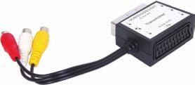
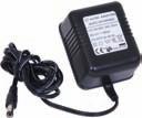
4 Intended use The device in intended exclusively for private, non-commercial use. The radio transmission set is suitable for audio and video equipment, such as: Televisions SAT receiver/set top boxes DVD/CD players PCs etc. The equipment must have the appropriate AV inputs/outputs. The radio transmission set is intended for: Wireless transmission of audio, video and infrared signals (transmission range up to 100 metres with no obstacles). No warranty is provided for damages resulting from improper use of the device! Package contents 1 Radio transmission set (1 x transmitter, 1 x receiver) 2 Connector power pack (6 V /300 ma) 1 SCART double adapter (labelled "TRANSMITTER") 1 SCART-CINCH adapter (labelled "RECEIVER") 2 CINCH (RCA cable, 3-wire 1 Infrared cable (infrared transmission diode cable for the remote control signals to be transmitted) 1 AUDIO adapter 3.5 mm mini-stereo male to CINCH female 1 Operating manual Important information: The enclosed AUDIO adapter may not be connected with the infrared connection socket (u) of the transmitter! This AUDIO adapter serves only for feeding in external audio signals. Technical data Power supply: Transmitter DC: 6 V /300 ma Receiver DC: 6 V /300 ma Manufacturer HON-KWANG ELECTRIC CO., LTD Model number: 0630EC- Input: 230 V ~ 50 Hz 30 ma Output : 6 V, 300 ma 1.8 VA Protection class: II / Interfaces: Audio R+L; Video (Cinch) IR EXT. (transmitter) (mini-stereo socket) Operating temperature: +5 ~ +35 C Humidity: 5 ~ 90% (co condensation) Dimensions Transmitter/ receiver unit: 118 x 90 x 140 mm Weight : Receiver 120 g Transmitter 110 g Mains adapter 170 g Video signal: 1 Vss (local TV switch in position "NO") Audio signal: 1 Vss (type) Transmission power: 10 mw Open space range: up to 100 m Within enclosed buildings or other locations, transmission disruptions (reflections) may arise that impair the image and sound quality
5 Safety instructions Please read the following information carefully. The operating manual must be stored safely and passed on to any future owners of the radio transmission set. Only use the product for the intended purpose as described in this operating manual. Risk of electric shocks. Set up the radio transmission set outside of the reach of children. Never allow children to play with the radio transmission set without supervision. Children could insert foreign objects into the openings on the device housing. Only connect the devices to a socket with a mains voltage of 230 V ~ / 50 Hz using the supplied mains adapters. Only insert the adapter plugs (connector power packs) into the labelled DC connection sockets on the respective devices. Protect the product from moisture. Use it only in dry rooms, do not use it outdoors or close to liquids. Make certain that neither the device nor the mains adapter could become wet or damp or sustain any other damage during use. When a storm and/or thunderstorm with the risk of lightening threatens, please disconnect the mains adapter from the mains power. Never allow any fluids to enter into the housing of the radio transmission set. Never submerse the device in water. Wipe it only with a slightly damp cloth. Do not operate the device if the mains adapter, the adapter's power cable or the device itself is damaged. Have a defective mains adapter repaired or replaced immediately by Customer Service. You are not permitted to open the housing of the radio transmission set or to modify it in any way. Otherwise, the warranty becomes void. Notice regarding separation from mains power To completely separate the device from mains power, the mains adapter must be unplugged from the wall socket. For this reason, the device should be used in a location where unobstructed access to the power socket is always assured so that you are able to immediately pull out the power plug in event of an emergency. To eliminate the risk of fire, prevent unintended activation and save energy costs, the mains adapter should be unplugged from the wall socket when the device is not in use. Always grip the power adapter directly when you wish to unplug it. Do not pull on the cord and never touch the mains adapter with wet hands as this could result in a short circuit or an electric shock. Do not place furniture or anything else on the cord of the mains adapter, and make sure that it does not become clamped. Never tie knots in the power cord, and do not join it to other cables. Run the mains adapter cord as well as any CINCH or infrared cable so that no one will step on it or trip over it. A damaged mains adapter can cause a fire or electric shock. Check the mains adapter from time to time
6 Should it become damaged, contact your nearest authorised customer service centre or your dealer to have it replaced. Risk of fire! Avoid plugging in the connector power pack immediately after moving the radio transmission set from a cold environment to a warm one. The temperature change could result in condensation that could damage the radio transmission set. Once the radio transmission set has reached room temperature, it can be safely put into operation. Do not place any open fire sources, such as candles, directly next to or on the device. Do not place any objects filled with liquid (e.g. vases) on the device. The connector power pack may not be covered because it becomes very warm during operation. Risk of suffocation! Do not leave packaging material lying unattended. Plastic sheets/bags, styrofoam parts, etc. can be dangerous toys for children. Do not bring the device into the vicinity of flammable gases or an explosive environment (e.g. paint shop) while the radio components are switched on since the transmitted radio waves could trigger an explosion or a fire. The range of the radio waves depends on ambient and environmental conditions. Risk of accidents and injury! This device is not intended for use by individuals (including children) with restricted physical, physiological or intellectual abilities or deficiencies in experience and/or knowledge unless they are supervised by a person responsible for their safety or receive from this person instruction in how the device is to be used. Children should be supervised to ensure that they do not play with the device. Damage to the device Do not expose the radio transmission set to high temperatures, direct sunlight, severe vibrations or high mechanical loads. Do not use any aggressive chemical substances for cleaning. Danger from radio signals! Switch the device off when in an airplane, hospital, operating room or in the vicinity of a medical electronic system. The transmitted radio waves could impair the function of sensitive devices. Keep the device at least 20 cm away from pacemakers since the proper functioning of the pacemaker could be impaired by radio waves. The transmitted radio waves can cause interference noises in audio equipment
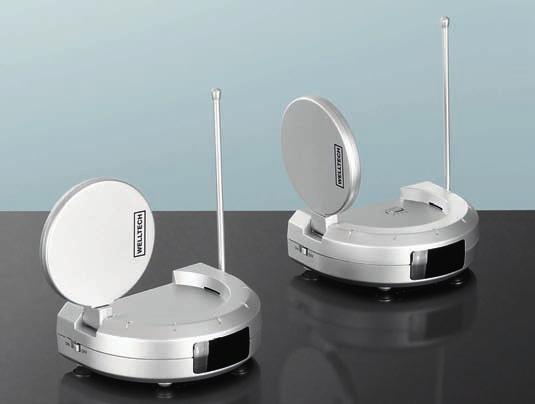
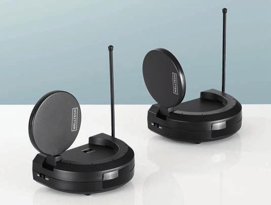
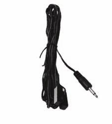
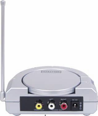
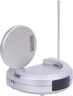
7 The device components Fig. A: The transmitter: q Antenna for transmission of the remote control signals w LED status indicator e Transmitter r Transmitter on/off switch t DC 6V connection socket for the supply voltage y Audio/video CINCH inputs u Infrared connection port (IR EXT.) i Local TV switch o Transmission channel switch a Audio/video transmission antenna Fig. B: The receiver: s Antenna for transmission of the remote control signals d Infrared receiver + LED f Receiver g Receiver on/off switch h Audio/video reception antenna j DC 6V connection socket for the supply voltage k Audio/video CINCH outputs l Reception channel switch (bottom of device) 1( SCART double adapter 2) SCART-CINCH adapter 2! CINCH (RCA) cable (2 included) 2@ Connector power pack (2 included) 2# Infrared cable 2$ AUDIO adapter 3.5 mm mini-stereo to CINCH female Glossary of useful concepts DC ( ) Direct Current, the type of power that is output by batteries and power supplies. In contrast, AC ( ~ ) stands for Alternating Current, the type of power supplied by the building mains (e.g. 230V AC). Connector power pack Component integrated into the power plug that converts the power from the building mains to the power (e.g. 6V DC) used by the device. LED Light Emitting Diode = a semi-conductor component that emits light. Generally used for indicators on the front of a device. The status indicator is an LED. Mini-stereo A type of plug. It exists in mono and stereo designs with diameters of 3.5 or 6.3 mm. It is frequently used due to its simple shape and easy handling. Used in audio equipment for microphones, headphones and PCs. Adapters exist for adapting to different plug types and diameters. IR EXT. This abbreviation refers to the infrared port. It is required for transmission of the remote control commands. CINCH (RCA) Called RCA in the United States. Coaxial connector frequently used for audio/video connections, in this case for connecting the radio transmission set to a television. An AV signal is transmitted with a three-pole CINCH (RCA) cable: red and white (audio signals) yellow (video signal) - 5 -
8 Composite video signal (CVBS) CVBS (colour, video, blank and sync), generally called composite video, refers to a normal video connection (VIDEO). The video signal is carried by a CINCH cable, generally labelled in yellow. SCART (EURO-SCART) Abbreviation for Syndicat des Constructeurs d Appareils Radio Recepteurs et Televiseurs. This is a French association for the radio and television industry. The connector is standardised 21-pin plug that is used between the television set and connected components, for example. AV socket Abbreviation for audio/video socket. Interface for transmitting sound and image signals (see SCART, CINCH). Video signal Electrical information that results in conversion of a real image into an electronic signal. The video signal has precisely defined properties and meets the currently applicable standard for video transmission. Frequency Number of oscillations or repetitions of a signal per second, measured in Hertz (Hz). Power supply The included connector power packs were certified by TÜV Rheinland. They are intended for operation on a 230V ~ / 50Hz mains network. Setting up the device First remove all device components from the packaging and remove all packing foil and tape. Important notice: Even when the system (transmitter + receiver) is switched off, the manufacturer still recommends disconnecting the connector power pack from the power network or using a power strip with a shut-off switch. Only this way can it be ensured that the device is completely powered down in the interests of economical use of power. Before starting up the device, please remove the notice from beneath the audio/video antenna. Connecting the transmitter Note: Select a transmission source. SAT receiver/set top box DVD/CD player VCR PC, etc. You can transmit video and audio signals from the selected transmission source. Connecting the transmission source to the transmitter: Connect the SCART double adapter ( 1() with a CINCH (RCA) cable (2!). Connect the CINCH (RCA) cable ( 2!) with the transmitter (e)
9 Note: Observe the colour coding: "White" CINCH plug to white CINCH socket "Red" CINCH plug to red CINCH socket "Yellow CINCH plug to yellow CINCH socket. Connect the SCART double adapter (1() to the AV socket of your transmission source (e.g. SAT receiver). Adjusting the transmitter signals The video transmitter (e) is designed so that a sufficiently high output voltage for faultless operation is supplied when simultaneously connected to a source (computer, DVD player, satellite receiver) together with other devices via the included adapter. The local TV switch (i) in the connection panel is then in the "YES" position. If only the video transmitter (e) is connected to the video source, without another device such as a DVD player/ VCR), image disruptions may occur for some device combinations. In this case, set the slider switch (i) to "NO" (= no additional device connected). This lowers the signal power so that the video and sound are transmitted without distortions. Note: If the AV socket of your transmission source is already in use, use the output of the SCART double adapter (1() for the original connection. Connect the infrared cable (2#) to the infrared connection socket (u) of the transmitter. Tape one of the self-adhesive transmission diodes of the infrared cable (2#) to the infrared receiver of your transmission source. Note: Avoid attaching the transmission diode directly to the infrared receiver of your transmission source. Direct remote control commands can now be issued as usual. Note: Use the remaining transmission diodes for additional devices. You can then connect these devices with the transmission source. Connect the transmitter (e) with a connector power pack (2@) using the 6 V DC connection socket (t). Connect the connector power pack (2@) with a 230 V ~ / 50 Hz wall socket. Use the "ON/OFF" switch (r), which is located on the side, to switch on the transmitter (e). Rotate the antenna for the remote control signals (q) upward. Orient the audio/video transmitter antenna (a). Important! The unlabelled side must point in the direction of the receiver (f). Switch on your transmission source. If necessary, start playback on your transmission source (e.g. SAT receiver/set top box, DVD/CD player, VCR, PC etc.). Connecting the receiver Connect the other CINCH (RCA) cable (2!) to the receiver (f) and the SCART- CINCH adapter (2)). Note: Be sure to match the colours correctly
10 Plug the SCART-CINCH adapter (2)) into the SCART socket of your TV. Connect the receiver to the other connector power pack using the 6 V DC connection socket (j). Connect the connector power pack (2@) with a 230V ~ /50 Hz wall socket. Use the "ON/OFF" switch (g), which is located on the side, to switch on the receiver (f). Important! The transmission channel switch (o) and the reception channel switch (l) must be set to the same channel. Otherwise radio transmission is not possible. Rotate the antenna for transmission of the remote control signals (s) upward. Orient the audio/video reception antenna (h) for the best image and sound quality. The unlabelled side of the antenna should point in the direction of the transmitter (e). Important! If necessary, try positioning the receiver (f) in a different location to avoid interference effects. Switch on your TV. You can use the following connection options on your TV. The AV socket (SCART/CINCH connection) Point the remote control of the transmission source at the infrared receiver (d) of the receiver (f). The commands are sent to your transmission source. Improving the transmission quality You can try the following measures to improve the quality in event of transmission disruptions: Orient the audio/video transmitter antenna or reception antenna (a, h) differently. Change the location of the transmitter (e) and/or the receiver (f). Change the position of the transmission diodes of the infrared cable (2#) on the infrared receiver of the transmission source. The remote control signal quality is improved. Try a different channel, either A, B, C or D. Depending on the image source (DVD player, SAT receiver, VCR, etc.) and the image contents (with large bright areas), overpowered video signals may occur in combination with certain TVs. These appear as distorted images. In this case, you can use the local TV switch (i) to adjust the transmission level and eliminate the distortions. Transmitter connection examples Note: In general: You can transmit signals from any device that outputs a sound and/or video signal on an appropriate connection: CD player DVD player VCR Television SAT receiver/set top box Video camera PC graphics card - 8 -
11 Special connection examples PC as transmission source You can transmit video signals from your PC if the PC has a graphics card with VIDEO output. For sound, use the 3.5 mm mini-stereo to CINCH female AUDIO adapter (2$). Connect the transmitter (e) to the video output of the graphics card. Note: Make certain that your PC is correctly configured for outputting video on the graphics card. Television as transmission source If video signals can be output via an AV socket on your TV, then the TV can be used as a transmission source. Please consult the operating manual of your TV for more information. Connect the transmitter (e) to an AV socket that may be used as an output. Note: Please note that most TVs must be switched on for a signal to be output on the AV socket. Image and sound information coming from the TV can then be transmitted. VCR as transmission source (Transmission of an audio/video signal, e.g. cable connection). Note: You can use the VCR as a tuner for transmitting audio/video signals. You can also switch the cable channels using the VCR Connect your VCR to a "cable connection". Program your video recorder for your "cable connection". Please consult the operating manual of your VCR for more information. Then connect the transmitter (e) of the radio transmission set to the AV socket of your VCR. Switch on the VCR. The VCR will transmit the configured "cable channels" to the transmitter (e) via the AV socket. Switch the "cable channels" on the receiver (f) using the remote control of the VCR. Channel configuration (parallel operation) Note: The data/signals sent from the transmitter are not encrypted. This means that compatible devices within the reception range are capable of eavesdropping on the signal. The radio transmission set uses an "open standard". Select between 4 different channels. Note: This makes it possible to operate up to 4 transmitters (e) in the same area. Make certain that the transmitter (e) and receiver (f) are set to the same channel. Expansion options Expand the radio transmission set by connecting multiple transmitters (e) or receivers (f).
12 Note: If you would like to control one device with multiple transmitters (e), you should only have one transmitter switched on at a time. This prevents transmission disruptions. Cleaning Transmitter Receiver Risk of electric shock! Disconnect the connector power pack (2@) from the wall socket if you would like to clean the radio transmission set. Important! Chemical cleansers may damage the radio transmission set. Clean the radio transmission set only with a slightly damp cloth. Troubleshooting If a problem arises, please check the following table first. If the problem cannot be corrected in this way, please call our service hotline. No audio/video transmission > >Are the transmitter ( e) and the receiver (f) switched on? >>Are the transmission channel switch (o) and the reception channel switch (l) set to the same channel? >>The range of the radio transmission set is reduced by walls and ceilings. Reduce the distance between the transmitter (e) and receiver (f). > >Reorient the transmission antenna ( a) of the transmitter (e) and the reception antenna (h) of the receiver (f) so that they point directly at each other. >>Check the CINCH and AV connections on the connected devices as well as on the transmitter (e) and receiver (f). >>If you are using other radio devices (same frequency), this may result in disruptions. This may also affect the range of the radio transmission set. >>The transmission source must be switched on (e.g. DVD player). Poor transmission quality >>Point the unlabelled sides of the transmission antenna (a) and reception antenna (h) directly at each other. > >Change the channel setting ( o/l) on both components. Make certain that the transmitter (e) and receiver (f) have the same setting. >>Slightly change the locations of the transmitter (e) and receiver (f) by a few centimetres. Various influences can produce transmission disruptions
13 >>Check the CINCH and AV connections on the connected devices as well as on the transmitter (e) and receiver (f). >>If you are using other radio devices (same frequency), this may result in disruptions. This may also affect the range of the radio transmission set. >>Distorted playback of bright images can be corrected with the local TV switch (i). Disruptions in remote control commands >>Point your remote control directly at the infrared receiver (d). Otherwise the commands cannot be executed. >>Tape the infrared transmission diodes of the infrared cable (2#) with a slight offset to the infrared receiver of the transmitting device. >>If you are using other radio devices (same frequency), this may result in disruptions. It may also affect the range of the radio transmission set. Disposal Do not throw the device in your normal domestic waste. This device is subject to the European directive 2002/96/ EC. Arrange for the product, or parts of it, to be disposed of by a professional disposal company or by your communal waste facility. Observe the currently applicable regulations. In case of doubt, please contact your waste disposal centre. Dispose of packaging materials in an environmentally responsible manner. CE conformity This device has been both examined and approved in regard to conformity with the fundamental requirements and other relevant regulations of the EMC directive 2004/108/EC and the low voltage directive (LVD) 2006/95/EC. Importer KOMPERNASS GMBH BURGSTRASSE BOCHUM, GERMANY Warranty and service You receive a 3-year warranty for this device as of the purchase date. The device has been manufactured with care and meticulously examined before delivery. Please retain your receipt as proof of purchase. In the case of a warranty claim, please contact our service department by telephone. Only this way can free shipping your goods be assured. The warranty covers only material or manufacturing faults, not normal wear or damage to fragile parts such as switches. The warranty covers only claims for material and manufacturing defects, not for worn parts or for damage to fragile components, e.g. buttons or batteries. The device is intended solely for private domestic use, not for commercial applications. In the event of misuse and improper handling, use of force and modifications not carried out by our authorised service centre, the warranty will become void. Your statutory rights are not restricted in any way by this warranty
14 DES Ltd Units Bilston Industrial Estate Oxford Street Bilston WV14 7EG Tel.: 0870/ Fax: 0870/ Irish Connection Harbour view Howth Co. Dublin Tel: (0) Fax:
15 KAZALO STRAN Namenska uporaba 14 Vsebina kompleta 14 Tehnični podatki 14 Navodila za varno uporabo 15 Sestavni deli izdelka 17 Kratka razlaga pojmov 17 Električno napajanje 18 Priprava na uporabo 18 Priklop oddajnika 18 Priklop sprejemnika 20 Kakovost prenosa 20 Primeri priklopa oddajnika 21 Primeri posebnih priklopov 21 Nastavitev kanalov (vzporedno delovanje) 22 Možne razširitve 22 Čiščenje 22 Iskanje in odprava napak 22 Odstranitev neuporabnega izdelka 23 Skladnost s standardom CE 23 Uvoznik 23 Garancija in servis 23 Pred prvo uporabo ta navodila za uporabo skrbno preberite in jih shranite za poznejšo uporabo. Ob predaji naprave tretji osebi izročite tudi navodila za uporabo
16 Namenska uporaba Aparat je dovoljeno uporabljati izključno za zasebne namene. Komplet za prenos signalov je namenjen za avdio- in videonaprave, kot so npr. televizijski sprejemnik, satelitski sprejemnik in digitalni pretvornik (STB), predvajalnik plošč DVD/CD, računalnik (PC), itd., ki imajo vhode in izhode AV. Namenska uporaba kompleta za prenos signalov obsega: brezžični prenos zvočnih, video- in infrardečih signalov (na prostem na razdalji do pribl. 100 metrov!). Za škodo, ki nastane zaradi nepredvidene uporabe izdelka, ne prevzamemo nobene odgovornosti! Vsebina kompleta 1 komplet za prenos signalov (1 oddajnik, 1 sprejemnik) 2 električna adapterja (6 V /300 ma) 1 dvojni adapter SCART (z oznako "TRANSMITTER" - ODDAJNIK) 1 adapter SCART-CINCH (z oznako "RECEIVER - SPREJEMNIK) 2 kabla CINCH (RCA), 3-žilna 1 infrardeči kabel (kabel z infrardečo oddajno diodo za prenos signalov daljinskega upravljalnika) 1 zvočni (AVDIO) adapter s 3,5 mm vtičem klinken na vtičnicah CINCH 1 navodila za uporabo Pomembno opozorilo: Priloženega zvočnega (AVDIO) adapterja ni dovoljeno priklapljati v infrardečo vtičnico (u) oddajnika! Ta adapter (AVDIO) je namenjen le za pošiljanje zunanjih zvočnih (avdio) signalov. Tehnični podatki Napajanje: Oddajnik DC: 6 V /300 ma Sprejemnik DC: 6 V /300 ma Proizvajalec HON-KWANG ELECTRIC CO., LTD Številka modela: 0630EC Vhod: 230 V ~ 50Hz 30mA Izhod: 6 V, 300mA 1,8 VA Razred zaščite: II / Priključki: Avdio R+L (desni in levi); video (cinch) IR EXT./ZUNANJI (oddajnik) (vtičnica klinken) Delovna temperatura: +5 ~ +35 C Vlaga: 5 ~ 90 % (brez kondenzacije) Dimenzije oddajnika/ sprejemnika: 118 x 90 x 140 mm Teža: sprejemnika 120 g oddajnika 110 g el. adapterja Videosignal: 170 g 1 Vss (stikalo Local TV v položaju NO/ NE) Avdiosignal: 1 Vss (tip.) Oddajna moč: 10 mw Doseg na prostem: do 100 m
17 V zaprtih delih zgradb ali na drugih krajih lahko pride do motenj pri prenosu zaradi odboja signala, ki močno poslabšajo kakovost slike in zvoka. Navodila za varno uporabo Naslednje informacije skrbno preberite. Navodila za uporabo skrbno hranite. Če boste komplet za prenos signalov izročili tretjim osebam, jim hkrati s kompletom obvezno izročite tudi navodilo za uporabo. Izdelek uporabljajte le za namene, navedene v tem navodilu za uporabo. Nevarnost zaradi električnega udara! Komplet za prenos signalov shranjujte na mestih, do katerih nimajo dostopa otroci. Poskrbite, da se otroci brez nadzora nikoli ne bodo mogli igrati s kompletom za prenos signalov. Otroci bi namreč lahko skozi odprtine na ohišju v izdelek potiskali različne predmete. Izdelke s priloženima električnima adapterjema priklapljajte izključno v električne vtičnice z napetostjo 230 V ~ /50 Hz. Vtiče električnih adapterjev priklapljajte le v označene vtičnice DC na posameznem izdelku. Izdelek zaščitite pred vlago. Izdelek uporabljajte le v suhih prostorih, ne na prostem ali v bližini tekočin. Pazite, da se izdelek in električni adapter med delovanjem ne bosta mogla zmočiti, navlažiti ali poškodovati. Pred nevihtami in/ali viharji z nevarnostjo udara strele električne adapterje izklopite iz električnih vtičnic. Poskrbite, da v ohišje kompleta za prenos signalov nikoli ne bodo stekle tekočine. Izdelka ne polagajte v vodo. Čistite ga le z rahlo navlaženo krpo. Izdelka ne uporabljajte, če so električni adapter, njegov kabel ali sam izdelek poškodovani. Pokvarjene električne adapterje dajte takoj popraviti oz. jih zamenjati z novimi na servisu. Ohišja kompleta za prenos signalov ni nikoli dovoljeno odpirati ali predelovati. V nasprotnem primeru garancija preneha veljati. Opomba glede izklopa iz električnega omrežja Za popoln izklop aparata iz električnega omrežja je potrebno električne adapterje potegniti iz električnih vtičnic. Zaradi tega izdelek uporabljajte tako, da boste vedno imeli neoviran dostop do električne vtičnice, da boste lahko v primeru sile električne adapterje takoj izklopili iz električne vtičnice. Da ne bi prišlo do požara, nenamernega vklopa in zaradi prihranka električne energije električna adapterja, ko izdelka ne uporabljate, praviloma vedno izklopite iz električnih vtičnic. Ko električni adapter želite izklopiti iz električne vtičnice, vedno primite za sam adapter. Ne vlecite za kabel in se adapterja tudi nikoli ne dotikajte z mokrimi rokami, ker to lahko povzroči kratki stik ali električni udar. Na kabel električnega adapterja ne postavljajte pohištva ali podobnega in pazite, da ne bo nikjer priprt. Kabla nikoli ne zavezujte v vozel in ga ne povezujte z drugimi kabli. Kabel električnega adapterja, pa tudi kabel CINCH in infrardeči kabel položite tako, da nihče ne bo mogel stopiti nanje oz. se obnje spotakniti
18 Poškodovan električni adapter lahko povzroči požar ali električni udar. Zato električni adapter občasno preglejte. Če je poškodovan, se obrnite na najbližji pooblaščen servis oz. trgovca, kjer bodo adapter zamenjali. Nevarnost požara! Ko komplet za prenos signalov prinesete iz hladnega v topel prostor, električnih adapterjev ne priklapljajte takoj. V nasprotnem primeru lahko kondenzirana voda komplet za prenos signalov uniči. Ko se komplet za prenos signalov segreje na sobno temperaturo, ga lahko uporabljate brez nevarnosti, da bi se uničil. Neposredno pred oz. na izdelek ne polagajte gorečih predmetov, npr. sveč. Na izdelek tudi ne polagajte s tekočino napolnjenih predmetov (npr. vaz). Električnih adapterjev ni dovoljeno pokrivati, ker se med delovanjem zelo segrejejo. Nevarnost zadušitve! Embalaže ne puščajte ležati naokoli. Plastične folije in vrečke, deli iz stiropora, itd. lahko v otroških rokah postanejo nevarne igrače. plinov ali v eksplozivno okolje (npr. v lakirnico), ker lahko oddani radijski valovi povzročijo eksplozijo ali požar. Doseg radijskih valov je odvisen od okolice, kjer se aparat nahaja. Nevarnost nesreč in telesnih poškodb! Ta izdelek ni namenjen temu, da bi ga uporabljale osebe (tudi otroci ne) z omejenimi fizičnimi, zaznavnimi ali duševnimi sposobnostmi ali s pomanjkljivimi izkušnjami in/ali znanjem, razen pod nadzorom osebe, ki je zanje odgovorna ali jim je dala navodila v zvezi z uporabo izdelka. Otroke je treba nadzorovati, da se z izdelkom ne bi igrali. Škodljivi vplivi Kompleta za prenos signalov ne imejte na visokih temperaturah, na mestih, kamor neposredno sijejo sončni žarki ali bi nanj delovali močni tresljaji ali mehanske obremenitve. Za čiščenje ne uporabljajte agresivnih kemičnih snovi. Nevarnost uporabe radijskih signalov! Aparat izklopite, če ste v letalu, bolnišnici, operacijski dvorani ali v bližini medicinskega elektronskega sistema. Oddani radijski valovi lahko motijo delovanje občutljivih naprav. Aparat imejte najmanj 20 cm stran od srčnega spodbujevalnika, sicer lahko radijski valovi negativno vplivajo na pravilno delovanje srčnega spodbujevalnika. Oddani radijski valovi lahko motijo slušne aparate. Aparata z vklopljeno radijsko komponento ne prinašajte v bližino vnetljivih
19 Sestavni deli izdelka Slika A: oddajnik: q antena za prenos signalov daljinskega upravljalnika w prikaz delovanja (LED) e oddajnik r stikalo oddajnika za vklop in izklop t vtičnica DC 6V za priklop električnega adapterja y avdio/video vhodi (CINCH) u infrardeča vtičnica (IR EXT./ZUN.) i stikalo za televizor (Local TV) o stikalo oddajnega kanala a oddajna antena za avdio/video Slika B: sprejemnik: s antena za prenos signalov daljinskega upravljalnika d infrardeči sprejemnik z diodo LED f sprejemnik g stikalo za vklop in izklop sprejemnika h antena za sprejem avdio in video signalov j vtičnica DC 6V za priklop električnega adapterja k izhodi CINCH za avdio/video l stikalo za nastavitev sprejemnega kanala (na spodnji strani) 1( dvojni adapter SCART 2) adapter SCART-CINCH 2! kabel CINCH (RCA) (2x) 2@ električni adapter (2x) 2# infrardeči kabel 2$ zvočni (AVDIO) adapter s 3,5 mm vtičem klinken na vtičnicah CINCH Kratka razlaga pojmov DC ( ) Direct Current, angleška oznaka enosmernega toka in napetosti, ki ju oddajajo npr. baterije in električni adapterji. Temu nasprotna je oznaka AC (za) izmenični tok in napetost, ki se uporabljata v električnem omrežju (npr. 230V AC). Električni adapter V električni vtič vgrajen sklop, ki izmenično napetost električnega omrežja spreminja v tako napetost (npr. v 6V DC), kot jo potrebuje aparat za svoje delovanje. LED Light Emitting Diode (dioda, ki oddaja svetlobo, svetilna dioda) = svetleča polprevodniška komponenta. Največkrat se uporablja za prikaz stanj v prednjih delih ohišij naprav. Taka dioda LED je npr. prikaz delovanja na izdelku. Klinken Okrajšava za vtič klinken. Obstajajo v izvedbah mono in stereo in premerih npr. 3,5 in 6,3 mm. Množično se uporabljajo zaradi enostavne sestave in preproste uporabe. V zvočni tehniki se uporabljajo pri mikrofonih, slušalkah in računalnikih. Različne vtične naprave in njihove različne premere je mogoče med seboj povezati z adapterji oz. prilagojevalniki. IR EXT. Okrajšava pomeni infrardeči vmesnik. Ta se uporablja za prenos ukazov daljinskega upravljalnika
20 CINCH (RCA) V Ameriki ga imenujejo tudi RCA. To je koaksialni vtični spoj, ki se pogosto uporablja za povezave oz. priklope, npr. za povezavo kompleta za prenos signalov in televizorja. Signal AV se prenaša po tripolnem kablu CINCH (RCA), rdečem in belem (za zvočne signale) in rumenem (za video signale). FBAS (priklop za VIDEO) S kratico FBAS (Farb-Bild-Austast- Synchronsignal, sinhroni signal za določanje signala barv in slike) označujemo običajni video priključek (VIDEO). Slikovni signal se prenaša po kablu CINCH, ki je največkrat rumen. SCART (EURO-SCART) Kratica za Syndicat des Constructeurs d Appareils Radio Recepteurs et Televiseurs. To je francosko združenje radijske in televizijske industrije. Vtični spoj je standardiziran in ima 21 polov, priklopi pa se npr. med televizijski sprejemnik in nanj priklopljene naprave. AV-vtičnica Kratica za vtičnico za avdio/video. To je vmesnik za prenos zvočnih in slikovnih signalov (glejte tudi SCART, CINCH). Videosignal Električna informacija, ki nastane iz pretvorbe dejanske slike v elektronski signal. Videosignal ima natančno določene lastnosti glede na veljavni standard za prenos slike. Frekvenca Število nihanj ali ponovitev signala na sekundo, merjeno v hercih (Hz). Električno napajanje Priložene električne adapterje je preizkusilo varnostno združenje TÜV Rheinland. Tako se lahko uporabljajo v električnih omrežjih z napetostjo 230V ~ /50Hz. Priprava na uporabo Najprej iz embalaže vzemite vse dele kompleta in z njih odstranite vse embalažne in nalepljene zaščitne folije. Vnaprejšnje pomembno opozorilo: Poleg izklopa naprav (oddajnika in sprejemnika) proizvajalec priporoča, da iz električnih vtičnic izklopite tudi električna adapterja ali da uporabite električni razdelilec s stikalom za izklop. Le tako bo izklop popoln, prispeval pa bo tudi k varčevanju z energijo. Pred začetkom uporabe odstranite opozorilo pod anteno za avdio in video. Priklop oddajnika Opomba: Izberite vir oddajanja: satelitski sprejemnik in digitalni pretvornik (STB) predvajalnik plošč DVD/CD videorekorder računalnik (PC), itd. Z izbranega vira oddajanja je mogoče prenašati signale za zvok in sliko. Vir oddajanja priklopite na oddajnik: Na dvojni adapter SCART ( 1() priklopite kabel CINCH (RCA) (2!). Kabel CINCH (RCA) ( 2!) priklopite na oddajnik (e)
21 Opozorilo: Skupaj priklapljajte kable in priključke enakih barv: "bela vtičnica CINCH in bel vtič CINCH, "rdeča vtičnica CINCH in rdeč vtič CINCH, "rumena vtičnica CINCH in rumen vtič CINCH. Dvojni adapter SCART (1() priklopite v vtičnico AV na viru oddajanja (npr. na satelitskem sprejemniku). Nastavitev moči signalov oddajnika Oddajnik za video (e) je narejen tako, da pri hkratnem priklopu na vir oddajanja (računalnik, predvajalnik DVD, satelitski sprejemnik) skupaj z drugimi aparati na priložen adapter pošilja dovolj močno izhodno napetost ter tako zagotavlja brezhibno delovanje. Takrat je stikalo za televizor (Local TV) (i) na zadnji strani oddajnika preklopljeno v položaj YES (DA). Če je na vir za sliko priklopljen le oddajnik za video (e) brez še enega aparata (npr. predvajalnika DVD ali videorekorderja), lahko pri nekaterih kombinacijah aparatov pride do motenj v sliki. V takem primeru premično stikalo za televizor (Local TV) (i) preklopite na NO (NE) (= brez dodatnega priklopljenega aparata). Signal bo tako šibkejši, prenos slike in tona pa brez motenj. Opomba: Če vtičnica AV vira oddajanja ni prosta, oddajnik priklopite na izhod dvojnega adapterja SCART (1(). Infrardeči kabel (2#) vklopite v infrardečo vtičnico (u) oddajnika. Eno od samolepilnih oddajnih diod infrardečega kabla (2#) prilepite na infrardeči sprejemnik vira oddajanja. Opozorilo: Oddajnih diod ne nameščajte neposredno na infrardeči sprejemnik vira oddajanja. Daljinski upravljalnik lahko sedaj uporabljate enako kot doslej. Opomba: Preostale oddajne diode uporabite za druge aparate. Tako aparate povežete z virom oddajanja. Na oddajnik (e) priklopite enega od električnih adapterjev (2@), tako da ga vklopite v vtičnico 6 V DC (t). Električni adapter (2@) priklopite v električno vtičnico 230 V ~ / 50 Hz. S stranskim stikalom za vklop in izklop (ON/OFF) (r) oddajnik (e) vklopite. Anteno za signale daljinskega upravljalnika (q) premaknite v navpični položaj. Usmerite tudi oddajno anteno (a) za zvok in sliko (avdio in video). Pomembno! Stran brez napisa mora biti obrnjena proti sprejemniku (f). Vklopite vir oddajanja. Odvisno od aparata na viru oddajanja vklopite še predvajanje (npr. na satelitskem sprejemniku, digitalnem pretvorniku (STB), predvajalniku plošč DVD/CD, videorekorderju, računalniku, itd.)
22 Priklop sprejemnika Drug kabel CINCH (RCA) (2!) priklopite na sprejemnik (f) in adapter SCART- CINCH (2)). Opozorilo: Tudi tukaj pazite, da bodo povezani deli enakih barv. Adapter SCART-CINCH (2)) priklopite v vtičnico SCART na televizijskem sprejemniku. Drug električni adapter priklopite v vtičnico 6 V DC (j) sprejemnika signalov. Električni adapter (2@) priklopite tudi v električno vtičnico 230V ~ /50 Hz. Nato s stranskim stikalom za vklop in izklop (ON/OFF) (g) sprejemnik (f) vklopite. Pozor! Stikalo oddajnega (o) in stikalo sprejemnega kanala (l) morata biti nastavljeni na isti kanal. Le tako je možen prenos signalov. Anteno za prenos signalov daljinskega upravljalnika (s) premaknite v navpični položaj. Sprejemno anteno za zvok in sliko (avdio in video) (h) usmerite tako, da bo kakovost slike in zvoka najboljša. Stran antene brez napisa mora biti obrnjena proti oddajniku (e). Pomembno! Za preprečitev motenj po potrebi prestavite sprejemnik (f) na drug kraj. Vklopite televizijski aparat. Možnosti priklopa televizijskega sprejemnika: vtičnica AV (povezava SCART/CINCH) Daljinski upravljalnik vira oddajanja usmerite proti infrardečemu sprejemniku (d) na sprejemniku signalov (f). Ukazi daljinskega upravljalnika se bodo izvedli na viru oddajanja. Kakovost prenosa Morebitne motnje med prenosom signalov lahko izboljšate na naslednje načine: Oddajno oz. sprejemno anteno (a, h) za zvok in sliko (avdio in video) usmerite drugam. Spremenite položaj oddajnika ( e) oz. sprejemnika (f). Spremenite mesto oddajnih diod infrardečega kabla (2#) na infrardečem sprejemniku vira oddajanja. S tem boste izboljšali kakovost signala daljinskega upravljalnika. Nastavite drug kanal, A, B, C ali D. Odvisno od vira slike (predvajalnik DVD, satelitski sprejemnik, videorekorder, itd.) in barv v njej (veliko svetlih površin) lahko v kombinaciji z določenimi televizijskimi aparati pride do prekomerne modulacije slike. To boste opazili v popačenih slikah. V takih primerih lahko moč oddajanja s stikalom za televizor (Local TV) (i) zmanjšate tako, da bodo popačenja izginila
23 Primeri priklopa oddajnika Opomba: Na splošna velja: Prenašati je mogoče signale vsakega aparata, ki ima ustrezen izhod in preko njega oddaja zvočni in slikovni signal: predvajalnik CD predvajalnik DVD videorekorder televizijski sprejemnik satelitski sprejemnik/digitalni pretvornik (STB) videokamera grafična kartica računalnika Primeri posebnih priklopov Računalnik kot vir oddajanja Prenos videosignalov z računalnika je mogoč, če ima grafična kartica v računalniku izhod VIDEO. Za prenos zvoka uporabite zvočni (AVDIO) adapter s 3,5 mm vtičem na vtičnicah CINCH (2$). Oddajnik (e) pa priklopite na videoizhod grafične kartice. Opomba: Da bo grafična kartica oddajala sliko tudi na izhod za video, mora biti računalnik ustrezno nastavljen. Televizijski sprejemnik kot vir oddajanja Če vaš televizijski sprejemnik na vtičnici AV oddaja videosignale, je lahko vir oddajanja. V zvezi s tem upoštevajte navodilo za uporabo televizijskega sprejemnika. Oddajnik (e) priklopite v vtičnico AV, ki se lahko uporablja kot izhod. Opomba: Upoštevajte, da mora biti večina televizijskih sprejemnikov vklopljena, šele takrat v vtičnico AV pošiljajo signal. Na ta način je mogoče prenašati slikovne in zvočne informacije, ki jih oddajnik dobi od televizijskega sprejemnika. Videorekorder kot vir oddajanja (prenos zvočnega in slikovnega signala kabelskega priključka). Opomba: Videorekorder lahko uporabite kot uglaševalnik (tuner) za prenos zvočnih in slikovnih signalov. Preko videorekorderja lahko speljete tudi kabelske programe. Videorekorder priklopite na kabelski priključek. Videorekorder nastavite, da bo sprejemal signale s kabelskega priključka. Pri tem upoštevajte navodila za uporabo videorekorderja. Nato oddajnik (e) kompleta za prenos signalov priklopite v vtičnico AV na videorekorderju. Videorekorder vklopite. Videorekorder bo nastavljene kabelske programe preko vtičnice AV prenašal na oddajnik (e). Z daljinskim upravljalnikom videorekorderja preklopite kabelske programe na sprejemniku (f)
24 Nastavitev kanalov (vzporedno delovanje) Opomba: Oddajnik podatkov oz. signalov, ki jih oddaja, ne kodira. Zato je, če se za frekvenčno območje oddajnika uporabijo združljive naprave, mogoče prisluškovanje. Gre za t.i. "odprti standard". Izbirate lahko med 4 različnimi kanali. Opomba: Na ta način lahko eden poleg drugega delujejo do 4 oddajniki (e). Pazite, da bosta oddajnik (e) in sprejemnik (f) nastavljena na isti kanal. Možne razširitve Komplet za prenos signalov lahko razširite tako, da priklopite več oddajnikov (e) ali sprejemnikov (f). Opomba: Če želite upravljati aparat z več oddajniki (e), vklopite le en oddajnik. Tako med prenosom ne bo prihajalo do motenj. Oddajnik Sprejemnik Čiščenje Nevarnost električnega udara! Pred čiščenjem kompleta za prenos signalov iz električnih vtičnic izklopite oba električna adapterja (2@). Pozor! Kemična sredstva za čiščenje lahko komplet za prenos signalov poškodujejo. Komplet za prenos signalov čistite le z rahlo navlaženo krpo. Iskanje in odprava napak Če se pojavijo težave, najprej preglejte naslednje poglavje. Če problema s tem ne rešite, pokličite našo telefonsko pomoč. Ni prenosa zvoka in slike > >Sta oddajnik ( e) in sprejemnik (f) vklopljena? > >Sta stikalo oddajnega kanala ( o) in stikalo sprejemnega kanala (l) nastavljeni na isti kanal? >>Doseg kompleta za prenos signalov zmanjšujejo zidovi in stropi. Zmanjšajte razdaljo med oddajnikom (e) in sprejemnikom (f). > >Oddajno anteno ( a) oddajnika (e) in sprejemno anteno (h) sprejemnika (f) ponovno postavite neposredno eno nasproti druge. >>Na priklopljenih aparatih ter na oddajniku (e) in sprejemniku (f) preverite priključke CINCH in AV. >>Če uporabljate druge elektronske naprave z istimi frekvencami, je lahko to vzrok za motnje. To lahko namreč dodatno skrajša doseg kompleta za prenos signalov
25 >>Vir oddajanja mora biti vklopljen (npr. predvajalnik DVD). Slaba kakovost prenosa > >Strani oddajne ( a) oz. sprejemne antene (h), na katerih ni napisov, znova namestite neposredno eno nasproti druge. > >Spremenite kanale ( o/l) obeh sistemov. Pri tem pazite, da bosta oddajnik (e) in sprejemnik (f) imela nastavljen enak kanal. > >Položaj oddajnika ( e) in sprejemnika (f) spremenite za nekaj centimetrov, ker lahko signal poslabšajo različni dejavniki. >>Na priklopljenih aparatih ter na oddajniku (e) in sprejemniku (f) preverite priključke CINCH in AV. >>Če uporabljate druge elektronske naprave z istimi frekvencami, je lahko to vzrok za motnje. To lahko namreč dodatno skrajša doseg kompleta za prenos signalov. >>Če so popačene svetle slike, to odpravite s preklopom stikala za televizor (Local TV) (i). Motnje ukazov daljinskega upravljalnika >>Daljinski upravljalnik usmerite neposredno v infrardeči sprejemnik (d). V nasprotnem primeru ta ne bo zaznal signalov daljinskega upravljalnika. >>Infrardeče oddajne diode infrardečega kabla (2#) nalepite na drugo mesto na infrardeči sprejemnik oddajajočega aparata. >>Če uporabljate druge elektronske naprave z istimi frekvencami, je lahko to vzrok za motnje. To lahko namreč dodatno skrajša doseg kompleta za prenos signalov. Odstranitev neuporabnega izdelka Aparata v nobenem primeru ne odvrzite med običajne gospodinjske odpadke. Za ta izdelek velja evropska direktiva 2002/96/EC. Izdelek ali njegove dele oddajte pri registriranem podjetju za odstranjevanje odpadkov ali pri najbližjem komunalnem podjetju. Upoštevajte trenutno veljavne predpise. Če ne veste točno, kaj storiti, se obrnite na najbližje podjetje za predelavo odpadkov. Vse embalažne materiale oddajte v reciklažo. Skladnost s standardom CE Ta izdelek je bil preizkušen in ima dovoljenje, da ustreza temeljnim zahtevam in drugim ustreznim predpisom direktive o elektromagnetni združljivosti 2004/108/EC in nizkonapetostne direktive (LVD) 2006/95/EC. Uvoznik KOMPERNASS GMBH BURGSTRASSE BOCHUM, NEMČIJA Garancija in servis Za ta izdelek vam priznamo 3 leta garancije od datuma nakupa. Izdelek je bil izdelan skrbno in pred dobavo natančno preverjen. Prosimo, da blagajniški račun shranite kot dokazilo o nakupu
26 V primeru uveljavljanja garancije se po telefonu obrnite na servis. Samo tako je zagotovljeno brezplačno pošiljanje vašega izdelka. Garancija velja samo za napake na materialu ali pri izdelavi, ne pa za obrabne dele ali za poškodbe lomljivih delov, npr. stikal. Garancijska storitev velja samo za napake na materialu ali pri izdelavi, ne pa za obrabne dele ali za poškodbe lomljivih delov, npr. stikal ali akumulatorjev. Izdelek je namenjen izključno za zasebno in ne za poslovno uporabo. V primeru zlorabe ali nepravilnega ravnanja, pri uporabi sile ter pri posegih, ki jih ni izvedel pooblaščen servis, garancija preneha veljati. Vaših zakonskih pravic ta garancija ne omejuje. Birotehnika Tkalčec Zlatko Andrija s.p. Lendavska ulica Murska Sobota Slovenija Phone: +386 (0) Fax: +386 (0) support.si@kompernass.com
27 SADRŽAJ STRANA Uporaba u skladu sa namjenom 26 Obim isporuke 26 Tehnički podaci 26 Sigurnosne napomene 27 Dijelovi uređaja 29 Proučavanje medija 29 Napajanje 30 Puštanje uređaja u rad 30 Priključak odašiljača 30 Priključak prijemnika 31 Poboljšanje kvalitete prijenosa 32 Primjeri priključivanja odašiljača 32 Posebni primjeri priključivanja 33 Podešavanje kanala (paralelni pogon) 33 Mogućnosti proširenja 34 Čišćenje 34 Traženje pogrešaka 34 Zbrinjavanje 35 CE-Konformitet 35 Uvoznik 35 Jamstvo i servis 35 Upute za rukovanje prije prve uporabe pažljivo pročitajte i sačuvajte ih za kasnije korištenje. Ukoliko uređaj dajete trećim osobama, priložite i ove upute
28 Uporaba u skladu sa namjenom Uređaj je namijenjen isključivo za privatnu uporabu. Komplet za bežični prijenos signala je prikladan za audio-, i videouređaje kao što su na primjer: TV-uređaj SAT receiver/set Top Box DVD/CD-player PC itd. sa AV-ulazima/izlazima. Uporabna namjena kompleta za bežični prijenos signala omogućava: Bežični prijenos audio-, video-, i infracrvenih signala (putanja prenošenja na slobodnom prostoru moguća do ca. 100 m!). Za štete, koje nastaju uslijed nenamjenske uporabe uređaja, ne preuzima se nikakvo jamstvo! Obim isporuke 1 Komplet za bežični prijenos signala (1 x odašiljač, 1 x prijemnik) 2 mrežna dijela utikača (6 V /300 ma) 1 SCART-dvostruki adapter (označen oznakom TRANSMITTER ) 1 SCART-CINCH-adapter (označen oznakom RECEIVER ) 2 CINCH-(RCA)-kabel 3-žilni 1 Kabel za infracrvene signale (Odašiljački diodni kabel za infracrvene signale daljinskog upravljača, koji se prenose) 1 AUDIO-adapter 3,5 mm cinch na CINCH-utičnice 1 Upute za rukovanje Važna napomena: Priloženi AUDIO-adapter ne smije biti utaknut u utičnicu za infracrveni priključak (u) odašiljača! Ovaj AUDIO-adapter služi isključivo za unošenje eksternih audio-signala. Tehnički podaci Napajanje: Odašiljač DC: 6 V /300 ma Prijemnik DC: 6 V /300 ma Proizvođač HON-KWANG ELECTRIC CO., LTD Broj modela: 0630EC- Ulaz: 230 V ~ 50Hz 30mA Izlaz: 6 V, 300mA 1,8 VA Zaštitna klasa: II / Priključci: Audio R+L; Video (Cinch) IR EXT. (odašiljač) (chinch-utičnica) Radna temperatura: +5 ~ +35 C Vlaga: 5 ~ 90 % (bez kondenzacije) Dimenzije Jedinica odašiljača/prijemnika: 118 x 90 x 140 mm Težina: Prijemnik 120 g Odašiljač 110 g Mrežni adapter 170 g Video-signal: 1 Vss (lokalni TV-prekidač u položaju NO ) Audio-signal: 1 Vss (tip) Snaga emitiranja: 10 mw Domet na slobodnom prostoru: do 100 m Unutar zatvorenih dijelova zgrade ili na drugim lokacijama može dolaziti do ometanja prijenosa (refleksija), te do izraženog umanjenja kvalitete slike i tona
29 Sigurnosne napomene Molimo da slijedeće informacije pažljivo pročitate. Upute za rukovanje morate pažljivo čuvati i eventualno zajedno sa kompletom za bežični prijenos signala predati trećim osobama. Ovaj proizvod koristite isključivo za dotičnu prikladnu uporabnu namjenu, u skladu sa ovim uputama za rukovanje. Opasnost od strujnog udara! Komplet za bežični prijenos signala postavite izvan domašaja djece. Djeci nikada ne dopustite da se bez nadzora igraju sa kompletom za bežični prijenos signala. Djeca bi mogla pokušati gurati razne predmete kroz otvore uređaja u njegovu unutrašnjost. Uređaje priključujte isključivo preko priloženih mrežnih adaptera na mrežnu utičnicu sa mrežnim naponom od 230 V ~ /50 Hz. Utaknite adapterske utikače (utične mrežne elemente) isključivo u označene DC-priključne utičnice dotičnog uređaja. Proizvod zaštitite od vlage. Koristite ga isključivo u suhim prostorijama, nikada na otvorenom prostoru ili u blizini tekućina. Obratite pažnju na to, da uređaj i mrežni adapter za vrijeme rada ne budu mokri ili vlažni, te da ne mogu biti oštećeni. Prije nevrjemena i/ili oluje sa opasnosti udara groma mrežni adapter odvojite od strujne mreže. Nikada ne dopustite da tekućine dospiju u kućište kompleta za bežični prijenos signala. Uređaj nikada ne uronite u vodu. Očistite ga samo pomoću blago navlažene krpe. Ne radite sa uređajem, kada su mrežni adapter, kabel mrežnog adaptera ili sam uređaj oštećeni. Defektne mrežne adaptere dajte neizostavno popraviti ili zamijeniti od strane servisa za kupce. Ne smijete nikada otvarati ili gradbeno preinačiti kućište kompleta za bežični prijenos signala. U protivnom jamstvo prestaje važiti. Napomene u vezi sa odvajanjem od strujne mreže Da biste uređaj potpuno odvojili od strujne mreže, morate mrežne adaptere izvući iz mrežne utičnice. Stoga uređaj trebate upotrebljavati tako, da u svakom trenutku bude osiguran neometani pristup mrežnoj utičnici, kako biste u slučaju opasnosti mrežni adapter mogli odmah iskopčati. Da biste isključili opasnost od nastanka požara i mogućnost nehotičnog uključivanja, te uštedili troškove energije, mrežne adaptere za vrijeme nekorištenja principijelno trebate odvojiti od mrežne utičnice. Mrežni adapter uvijek neposredno zahvatite, ako ga želite iskopčati iz utičnice. Ne povlačite za kabel, i nikada ne dotaknite mrežni adapter mokrim rukama, jer bi to moglo dovesti do kratkog spoja ili strujnog udara. Ne postavljajte namještaj i sl. na kabel mrežnog adaptera i obratite pažnju, da ovaj kabel ne bude prignječen. Nikada ne vežite kabel u čvor i ne povezujte ga sa drugim kablovima. Postavite kabel mrežnog adaptera, a eventualno i CINCH-, odnosno infracrveni kabel tako, da nitko ne može stati na njega ili se preko njega protepsti. Oštećeni mrežni adapter može prouzrokovati požar ili strujni udar. Sa vremena na vrijeme prekontrolirajte mrežni adapter
AVS50 USER GUIDE. 2.4GHz Audio/Video Sender System - AVS50
 2.4GHz Audio / Video Sender System AVS50 USER GUIDE 2.4GHz Audio/Video Sender System CONTENTS 1. Introduction... 2 2. Conformity of Use... 3 3. Controls and Connections... 4-5 4. Product Contents... 6
Owner s Manual LED COMMANDER 16/2
 Owner s Manual LED COMMANDER 16/2 Content Introduction...2 Technical Specification...2 Maintenance and care...2 Notes on safety...3 Features...4 Overview...5 Installation...6 Operation...6 Channel Assignment...7
Package Contents Connections and Controls... 5 Front of the active Subwoofer... 5 Rear of the active Subwoofer... 6
 Table of Contents: Safety and Service... 2 Operational Safety... 2 Location... 2 Ambient Temperature... 3 Electromagnetic Compliance... 3 Service... 4 Cleaning... 4 Disposal... 4 Package Contents... 4
Ambient Temperature...3 Electromagnetic Compliance...3
 TABLE OF CONTENTS: SAFETY AND SERVICE... 2 Operational Safety... 2 Location... 2 Ambient Temperature...3 Electromagnetic Compliance...3 Service... 3 Cleaning... 3 Package Contents... 4 Specifications...
TV Ears Wireless Speaker User Manual
 TV Ears Wireless Speaker User Manual Congratulations! You ve taken the first step toward the TV Ears television experience. TV Ears Wireless System will help you hear TV better. To ensure the best TV listening
AITech ProA/V Media Extender Mini. User Manual
 AITech ProA/V Media Extender Mini User Manual Package Contents x 1 x 1 Infrared (IR) eye cable x 1 Remote antenna x 1 Audio/Video cable x 2 Power adaptors (DC6V) x 2 User manual x 1 Note: The transmitter
User s Guide. 5.8GHz Wireless A/V Signal Sender
 1500332 User s Guide 5.8GHz Wireless A/V Signal Sender Thank you for purchasing your A/V Signal Sender from RadioShack. Please read this user s guide before installing, setting up, and using your new sender.
LINK-MI LM-WHD05B. Wireless HDMI AV Transmission System. User Manual
 LINK-MI LM-WHD05B Wireless HDMI AV Transmission System User Manual Table of Contents 1.Important Information... 3 1.1 Safety Precautions... 3 1.2 Declaration of Conformity... 4 1.3 Trademark Information...
Children cannot always recognize potential hazards properly. This 5.1 system is not designed for operation in a heavy industry environment.
 5.1 FLAT PANEL SPEAKER SYSTEM WITH POWERED SUBWOOFER Table of Contents: SAFETY AND SERVICE... 2 Operational Safety... 2 Location... 2 Ambient Temperature... 3 Electromagnetic Compliance... 3 Service...
2.4 GHz WIRELESS SURVEILLANCE SYSTEM
 2.4 GHz WIRELESS SURVEILLANCE SYSTEM Operating Instructions Tested Comply With FCC Standards Model # TBM-18 BEFORE OPERATING THIS PRODUCT, READ, UNDERSTAND, AND FOLLOW THESE INSTRUCTIONS. Be sure to save
Achat 115 Sub A active subwoofer. user manual
 Achat 115 Sub A active subwoofer user manual Musikhaus Thomann Thomann GmbH Hans-Thomann-Straße 1 96138 Burgebrach Deutschland Telephone: +49 (0) 9546 9223-0 E-mail: info@thomann.de Internet: www.thomann.de
TV Ears TV Speaker Installation Guide
 TV Ears TV Speaker Installation Guide Safety Instructions 1. Read all instructions completely and heed all warnings. Install in accordance with TV Ears, Inc. s instructions. 2. Keep these instructions
User manual Hardware manual. Casablanca S series S-2000 / S-4000 / S-4100
 User manual Hardware manual Casablanca S series S-2000 / S-4000 / S-4100 The following products carry the CE seal of conformity on the basis of the guidelines 89/336/EWG of the Commission of the European
Connect 350 UHD. Connect 350 UHD USER MANUAL 3 GEBRAUCHSANLEITUNG GUIDE UTILISATEUR MODO DE EMPLEO MANUALE D ISTRUZIONI GEBRUIKSAANWIJZING
 Connect 350 UHD Connect 350 UHD USER MANUAL 3 GEBRAUCHSANLEITUNG GUIDE UTILISATEUR MODO DE EMPLEO MANUALE D ISTRUZIONI GEBRUIKSAANWIJZING 20633/ 20141127 Connect 350 UHD ALL RIGHTS RESERVED MARMITEK 2
ASP-FIBRS1 User Manual
 ASP-FIBRS1 HDMI Single Fiber Extender with Serial and IR User Manual Manual Number: 100823 Safety and Notice The ASP-FIBRS1 HDMI Extender over 1 fiber with serial and IR have been tested for conformance
In-Ceiling Electric Motorized Front Projection Screen Evanesce Series. User s Guide
 In-Ceiling Electric Motorized Front Projection Screen Evanesce Series User s Guide Important Safety & Warning Precautions Make sure to read this user s guide and follow the procedures below. Caution: The
NECT 540 U CONNECT 540 UHD USER MANUAL 3 GEBRAUCHSANLEITUNG GUIDE UTILISATEUR MODO DE EMPLEO MANUALE D ISTRUZIONI GEBRUIKSAANWIJZING
 NECT 540 U CONNECT 540 UHD USER MANUAL 3 GEBRAUCHSANLEITUNG GUIDE UTILISATEUR MODO DE EMPLEO MANUALE D ISTRUZIONI GEBRUIKSAANWIJZING 20636/20141127 CONNECT 540 UHD ALL RIGHTS RESERVED MARMITEK 2 MARMITEK
Instructions Manual
 15 19 22 26 32 42 46 55 65 Instructions Manual Table of Contents Safety Guidelines Safety Guidelines 3 Package Contents 4 Ports and Connectors 5 Technical Specifications 6 Installation Guidelines 7 Installation
Indoor/Outdoor Security System with Quad Monitor User s Manual
 Indoor/Outdoor Security System with Quad Monitor User s Manual 4919539 Important! Please read this booklet carefully before installing or using these units. WARNING - These units should ONLY be opened
Limited Warranty. TERK and the TERK logo are registered trademarks of AUDIOVOX Corp.
 Limited Warranty Audiovox Corporation (Audiovox) warrants this product against defects in materials or workmanship for one (1) year from the date of purchase. During this period, this product will be replaced
Thank you for purchasing the X-Dream Rocker From. Web: We know you will enjoy your X-Dream Rocker experience as much as we do.
 Thank you for purchasing the X-Dream Rocker From www.boysstuff.co.uk/ the largest range of gaming chairs anywhere in the UK We know you will enjoy your X-Dream Rocker experience as much as we do. Welcome
MANUAL ENGLISH Core Club Ordercode: D2314
 MANUAL ENGLISH Core Club Ordercode: Highlite International B.V. Vestastraat 2 6468 EX Kerkrade the Netherlands Table of contents Warning... 2 Unpacking Instructions... 2 Safety Instructions... 2 Operating
Concert Series ORDERCODE D3470 ORDERCODE D3471 ORDERCODE D3472 D3470 D3471 D3472
 Concert Series ORDERCODE D3470 ORDERCODE D3471 ORDERCODE D3472 D3470 D3471 D3472 Congratulations! You have bought a great, innovative product from DAP Audio. The DAP Audio Concert Series brings excitement
SATRI AMPLIFIER AMP-51R. Owner s Manual
 SATRI AMPLIFIER AMP-51R Owner s Manual contents SAFETY INSTRUCTIONS 4 INTRODUCTION 6 OVERVIEW (FRONT PANEL) 8 OVERVIEW (REAR PANEL) 9 OVERVIEW (REMOTE CONTROL) 1 1 OPERATION 12 TROUBLESHOOTING 13 SPECIFICATION
STAGE 250. Owner s Manual TRANSPORTABLE PA WITH BUILT-IN MIXER AND 24 BIT EFFECTS
 STAGE 250 Owner s Manual TRANSPORTABLE PA WITH BUILT-IN MIXER AND 24 BIT EFFECTS Important Safety Instructions For your own safety you must read this section in full first! Intended use This device is
MONOPRICE. Blackbird 4K Pro HDBaseT Extender Kit. User's Manual P/N 21609
 MONOPRICE Blackbird 4K Pro HDBaseT Extender Kit P/N 21609 User's Manual SAFETY WARNINGS AND GUIDELINES Please read this entire manual before using this device, paying extra attention to these safety warnings
190V3.
 190V3 www.philips.com/welcome Kazalo vsebine 1. Pomembno...1......... 2. Namestitev monitorja...4...4...5...7 3. Optimizacija slike...9...9...9...16... 5. Upravljanje napajanja...21 6. Informacije o predpisih...22...28......
DSP 18 Sub active subwoofer. user manual
 DSP 18 Sub active subwoofer user manual Musikhaus Thomann Thomann GmbH Hans-Thomann-Straße 1 96138 Burgebrach Germany Telephone: +49 (0) 9546 9223-0 E-mail: info@thomann.de Internet: www.thomann.de 05.11.2018,
TV Connector user guide
 TV Connector user guide Thank you Thank you for choosing the TV Connector. The intended use of the TV Connector is to connect your hearing aids directly to your TV or audio source. Your TV Connector Hearing
SAFETY INFORMATION. 7. Do not force switched or external connections in any way. They should all connect easily, without needing to be forced.
 SAFETY INFORMATION 1. To ensure the best results from this product, please read this manual and all other documentation before operating your equipment. Retain all documentation for future reference. 2.
 Register your product and get support at www.philips.com/welcome SWW1890 User manual Contents 1 Important 4 Safety 4 English 2 Your Philips Wireless HD Net Connect 5 What is in the box 5 3 Overview 6
BT Diverse Repeater. User Guide
 BT Diverse Repeater User Guide Section Welcome to your BT Diverse Repeater Range Extender Extends the range in which you can make and receive calls from your existing DECT base station by up to 50m indoors
USER MANUAL. KW-11T Wireless High Definition Transmitter. KW-11R Wireless High Definition Receiver MODELS: P/N: Rev 9
 KRAMER ELECTRONICS LTD. USER MANUAL MODELS: KW-11T Wireless High Definition Transmitter KW-11R Wireless High Definition Receiver P/N: 2900-300194 Rev 9 Contents 1 Introduction 1 2 Getting Started 2 2.1
User Manual. AtlonA COMPOSITE VIDEO (BNC) + STEREO AUDIO TO HDMI VIDEO FORMAT CONVERTER AND SCALER AT-HD120
 + STEREO AUDIO TO HDMI VIDEO FORMAT CONVERTER AND SCALER AT-HD120") User Manual AtlonA COMPOSITE VIDEO (BNC) + STEREO AUDIO TO HDMI VIDEO FORMAT CONVERTER AND SCALER AT-HD120 TABLE OF CONTENTS 1. Introduction... 3 2. Package Contents... 3 3. Features... 3 4. Specification...
User Manual AtlonA COMPOSITE VIDEO (BNC) + STEREO AUDIO TO HDMI VIDEO FORMAT CONVERTER AND SCALER AT-HD120 TABLE OF CONTENTS 1. Introduction... 3 2. Package Contents... 3 3. Features... 3 4. Specification...
Wireless 5.8GHz AV Sender With Built in Remote Control Extender
 Wireless 5.8GHz AV Sender With Built in Remote Control Extender AR-1913 User Manual TABLE OF CONTENTS Box Contents..................2 User Guide.............3 Installation............4 Trouble Shooting............
Advanced security made easy PRO-555. Day/Night CCD Security Camera. Operating Instructions SW331-PR5 SR331-PR
 Advanced security made easy PRO-555 Day/Night CCD Security Camera Operating Instructions SW331-PR5 www.swannsecurity.com SR331-PR5-60010-260809 1 Before You Begin FCC Verification: NOTE: This equipment
Picture Fan. display your photos, graphics & messages
 Picture Fan display your photos, graphics & messages Table of contents Warnings and Cautions....1 FCC Information...5 Location of Parts and Controls....6 Home Screen App Control...7 Picture Fan Operation....8
VLHDMIEXTFIB_2017V1.0
 User Manual VLHDMIEXTFI ll Rights Reserved Version: VLHDMIEXTFI_2017V1.0 Preface Read this user manual carefully before using the product. Pictures are shown in this manual for reference only, different
User Guide. Interton TV Streamer
 User Guide Interton TV Streamer Welcome Congratulations on your purchase of a Interton TV Streamer. Interton TV Streamer will provide you with high quality streamed audio from your TV, HiFi stereo, personal
USER MANUAL. DV-HSW-41 HDMI 4x1 SWITCHER LIT Bergen Boulevard, Woodland Park, NJ Tel FAX Web
 USER MANUAL DV-HSW-41 HDMI 4x1 SWITCHER 244 Bergen Boulevard, Woodland Park, NJ 07424 Tel 973-785-4347 FAX 973-785-3318 Web www.fsrinc.com LIT1372 PROPRIETARY INFORMATION All information in this manual
User Manual PS-684. HDBaseT Extender Kit 70m. All Rights Reserved. Version: UHBT70P_2016V1.2
 User Manual PS-684 All Rights Reserved Version: UHBT70P_2016V1.2 Preface Read this user manual carefully before using this product. Pictures shown in this manual is for reference only, different model
MONOPRICE. Blackbird 4K HDBaseT Extender Kit. User's Manual P/N 21792
 MONOPRICE Blackbird 4K HDBaseT Extender Kit P/N 21792 User's Manual SAFETY WARNINGS AND GUIDELINES Please read this entire manual before using this device, paying extra attention to these safety warnings
2.4 GHz WIRELESS VIDEO SENDER SYSTEM MODEL: VS6234
 2.4 GHz WIRELESS VIDEO SENDER SYSTEM MODEL: VS6234 Please read this manual thoroughly before operating this system OPERATING INSTRUCTIONS 03/02 1 SAFETY INSTRUCTIONS CAUTION! RISK OF ELECTRIC SHOCK. DO
28 4K LED monitor. User Manual M284K
 28 4K LED monitor User Manual M284K CONTENTS Safety Information... 2 What s included..... 4 Getting Started....... 8 Troubleshooting.... 14 Specification.... 15 2 of 15 SAFETY INFORMATION Read these instructions
Electric Wall/Ceiling Projection Screen Saker Plus Series User s Guide
 Electric Wall/Ceiling Projection Screen Saker Plus Series User s Guide Important Safety & Warning Precautions Make sure to read this user s guide and follow the procedures below. Caution: The screen s
User Manual. 4x2 Composite Video/S-Video/Analog Audio Matrix Switcher AT-SAV-42M
 User Manual 4x2 Composite Video/S-Video/Analog Audio Matrix Switcher AT-SAV-42M www.atlona.com TABLE OF CONTENTS 1. Introduction... 2 2. Features... 2 3. Package Contents... 2 4. Specification... 3 5.
Home Roam TV Basic User Manual
 Page1 Home Roam TV Basic User Manual Table of Contents 1. Safety Disclaimer... 2 2. Introduction... 2 3. What s in the Box... 2 4. Specifications... 2 5. Unit Functions... 3 5-1. Transmitter Module...
MONOPRICE. Blackbird 4K HDMI Extender. User's Manual P/N 24281
 MONOPRICE Blackbird 4K HDMI Extender P/N 24281 User's Manual SAFETY WARNINGS AND GUIDELINES Please read this entire manual before using this device, paying extra attention to these safety warnings and
Subwoofers ENGLISH FRANCAIS SPANISH DEUTSCH OWNER S MANUEL MODE D EMPLOI MANUEL DEL USUARIO BEDIENUNGSANLEITUNG
 ENGLISH FRANCAIS SPANISH DEUTSCH Subwoofers OWNER S MANUEL MODE D EMPLOI MANUEL DEL USUARIO BEDIENUNGSANLEITUNG Titan 5.6 Titan 7.6 MK2 Titan 11.6 MK2 Titan 15.6 MK2 MOSSCADE BP 306-94709 Maisons-Alfort
ACCESSORIES MANUAL PART NUMBER: TNP500. Universal Tilt N Plug Interconnect Box USER'S GUIDE
 MANUAL PART NUMBER: 400-0091-003 TNP500 Universal Tilt N Plug Interconnect Box USER'S GUIDE INTRODUCTION Your purchase of the TNP100 Tilt N Plug Interconnect Box is greatly appreciated. We are sure you
INSTALLATION GUIDE ConnectLine TV adapter Getting started
 INSTALLATION GUIDE ConnectLine TV adapter Getting started PURPOSE OF THIS GUIDE READ THIS FIRST Before your hearing instruments can receive the TV sound, the adapter must be connected to the TV and a power
Black & White Wireless Video Surveillance System
 MODEL: 2BWIR Black & White Wireless Video Surveillance System INSTALLATION MANUAL V1.0 N517 Camera Monitor - Compact 2.4 GHz Mini Black & White Camera - 5.5 High Resolution CRT - Sturdy Design with Metal
Spectra Batten (Order code: LEDJ95)
") www.prolight.co.uk Spectra Batten (Order code: LEDJ95) Safety WARNING FOR YOUR OWN SAFETY, PLEASE READ THIS USER MANUAL CAREFULLY BEFORE YOUR INITIAL START-UP! CAUTION! Keep this equipment away from rain,
www.prolight.co.uk Spectra Batten (Order code: LEDJ95) Safety WARNING FOR YOUR OWN SAFETY, PLEASE READ THIS USER MANUAL CAREFULLY BEFORE YOUR INITIAL START-UP! CAUTION! Keep this equipment away from rain,
Stratos Duo RGB. User Manual. Order code: EQLED371
 Stratos Duo RGB User Manual Order code: EQLED1 Safety advice WARNING FOR YOUR OWN SAFETY, PLEASE READ THIS USER MANUAL CAREFULLY BEFORE YOUR INITIAL START-UP! Before your initial start-up, please make
LF-IRX. 12 Month Limited Warranty LF-IRX. Remote Control Extender. Owner s manual. For customer service and technical information::
 12 Month Limited Warranty Audiovox Electronics Corporation (the company) warrants to the original purchaser of this product that should this product or any part thereof, under normal use and conditions,
User Manual MagniLink Mira
 User Manual MagniLink Mira LVI Low Vision International Verkstadsgatan 5 Tel: +46 470 727700 E-mail: info@lvi.se 352 46 Växjö SWEDEN Fax: +46 470 727725 Internet: www.lvi.se CONTENTS 1. GENERAL INFORMATION...
226V3L.
 226V3L www.philips.com/welcome Kazalo vsebine 1. Pomembno...1......... 2. Namestitev monitorja...4...4...5... 3. Optimizacija slike...9...9...9...16... 5. Upravljanje napajanja...20 6. Informacije o predpisih...21...27......
DH551C/DH550C/DL550C Double Sided Display User Manual
 DH551C/DH550C/DL550C Double Sided Display User Manual Disclaimer BenQ Corporation makes no representations or warranties, either expressed or implied, with respect to the contents of this document. BenQ
By CHANNEL VISION. Flush Mount Amplifier A0350
 Spkrs Local In IR In 24VDC A0350 10 The A0350 can be used with Channel Vision s CAT5 audio hubs to provide a powerful 50Watts per channel in the listening zone. Alternatively, the A0350 can be added to
MONOPRICE. Multiformat to SDI Converter with Scaler. User's Manual P/N 15775
 MONOPRICE Multiformat to SDI Converter with Scaler P/N 15775 User's Manual SAFETY WARNINGS AND GUIDELINES This device is intended for indoor use only. Do not expose this device to water or moisture of
1 x 10 Component Video with Stereo and Digital Audio Distribution Amplifier over CAT5/6 compatible with AT-COMP300RL AT-COMP10SS
 1 x 10 Component Video with Stereo and Digital Audio Distribution Amplifier over CAT5/6 compatible with AT-COMP300RL AT-COMP10SS User Manual www.atlona.com TABLE OF CONTENTS 1. Introduction 2 2. Features
User Instructions. 16 SCB Sync Station.
 User Instructions 16 SCB Sync Station Contents Overview... 1 Specifications... 1 Compliance and approvals... 2 Safety instructions... 3 Set up... 4 How to charge multiple devices... 4 How to synchronize
HDMI WIRELESS EXTENDER/ RECEIVER. Vanco Part Number: HDWIRKIT HDWIR-RX. Technical Support
 HDMI WIRELESS EXTENDER/ RECEIVER Vanco Part Number: HDWIRKIT HDWIR-RX Technical Support www.vanco1.com techsupport@vanco1.com 800-626-6445 DEAR CUSTOMER Thank you for purchasing this product. For optimum
Owner s Manual DMX MASTER I & II
 Owner s Manual DMX MASTER I & II Content Introduction...2 Technical Specification...2 Maintenance and care...2 1. Notes on safety...3 2. General Instructions...3 3. Overview...5 4. Operation Guide...7
COMPOSITE VIDEO (BNC) TO VGA VIDEO FORMAT CONVERTER AND SCALER AT-RGB110
 TO VGA VIDEO FORMAT CONVERTER AND SCALER AT-RGB110") User Manual COMPOSITE VIDEO (BNC) TO VGA VIDEO FORMAT CONVERTER AND SCALER AT-RGB110 TABLE OF CONTENTS 1. Introduction... 2 2. Package Contents... 2 3. Features... 2 4. Specification... 2 5. Panel Description...
User Manual COMPOSITE VIDEO (BNC) TO VGA VIDEO FORMAT CONVERTER AND SCALER AT-RGB110 TABLE OF CONTENTS 1. Introduction... 2 2. Package Contents... 2 3. Features... 2 4. Specification... 2 5. Panel Description...
User Manual TL-2X1-HDVC 2x1 HDMI & VGA Switcher with Control All Rights Reserved Version: TL-2X1-HDVC_160630
 User Manual TL-2X1-HDVC 2x1 HDMI & VGA Switcher with Control All Rights Reserved Version: TL-2X1-HDVC_160630 Preface Read this user manual carefully before using this product. Pictures shown in this manual
Electro Magnetic Compatibility (EMC) Warning. Important notes for users in the U.K. FCC declaration. Caution. Fuse
 Warning. Important notes for users in the U.K. FCC declaration. Caution. Fuse") Warning: to prevent fire or shock hazard, do not expose camera or monitor to rain or moisture. The lightning flash with arrowhead symbol, within a triangle, is intended to alert the user to the presence
Warning: to prevent fire or shock hazard, do not expose camera or monitor to rain or moisture. The lightning flash with arrowhead symbol, within a triangle, is intended to alert the user to the presence
AUDIO WIRELESS. with IR Extender Feature OWNER S MANUAL SENDER T CAT. NO
 /V WIRELESS AUDIO UDIO/V /VIDEO SENDER with IR Extender Feature OWNER S MANUAL SENDER 15-2572T CAT. NO. 15-2572 SENDER 15-2572T FCC CAUTION THIS DEVICE COMPLIES WITH PART 15 OF THE FCC RULES. OPERATION
EXT-HBT70-SET_2016V1.2
 USER MANUAL EXT-HBT70-SET HDBaseT Extender Set 70m All Rights Reserved Version: EXT-HBT70-SET_2016V1.2 Preface Read this user manual carefully before using this product. Pictures shown in this manual is
Stretch HDMI TM. User s Manual (M1-2000)
") Stretch HDMI TM User s Manual (M1-2000) Manual Contents Manual Contents 1-0 Welcome!, Product Description 1-1 System Requirements for Setup 1-2 Installation 1-3 Troubleshooting, Maintenance, Technical
Stretch HDMI TM User s Manual (M1-2000) Manual Contents Manual Contents 1-0 Welcome!, Product Description 1-1 System Requirements for Setup 1-2 Installation 1-3 Troubleshooting, Maintenance, Technical
DIGITAL SET TOP BOX STB 7017 INSTRUCTION MANUAL
 DIGITAL SET TOP BOX STB7017 INSTRUCTION MANUAL STB 7017 CHANNEL After Sales Support Now you have purchased a Tevion product you can rest assured in the knowledge that as well as your 3 year parts and labour
Miniature Fiber-Optic 3G-SDI Extension Module. User s Manual (SDIX-100, SDIX-100C)
") Miniature Fiber-Optic 3G-SDI Extension Module User s Manual (SDIX-100, SDIX-100C) Manual Contents Manual Contents 1-0 Welcome!, Product Description 1-1 System Requirements for Setup 1-2 Installation 1-3
Miniature Fiber-Optic 3G-SDI Extension Module User s Manual (SDIX-100, SDIX-100C) Manual Contents Manual Contents 1-0 Welcome!, Product Description 1-1 System Requirements for Setup 1-2 Installation 1-3
VGA / Audio Extender Single CAT5 / CAT6 with RGB Delay Control & EQ
 AV Connectivity, Distribution And Beyond... VIDEO WALLS VIDEO PROCESSORS VIDEO MATRIX SWITCHES EXTENDERS SPLITTERS WIRELESS CABLES & ACCESSORIES VGA / Audio Extender Single CAT5 / CAT6 with RGB Delay Control
KHT 1000C HV-Probe Calibrator. Instruction Manual
 KHT 1000C HV-Probe Calibrator Instruction Manual Copyright 2015 PMK GmbH All rights reserved. Information in this publication supersedes that in all previously published material. Specifications are subject
Evolution Digital HD Set-Top Box Important Safety Instructions
 Evolution Digital HD Set-Top Box Important Safety Instructions 1. Read these instructions. 2. Keep these instructions. 3. Heed all warnings. 4. Follow all instructions. 5. Do not use this apparatus near
Instruction Guide. The TV Jockey Computer Monitor TV Tuner with Remote COMP2VGATVGB. The Professionals Source For Hard-to-Find Computer Parts
 VIDEO ADAPTER The TV Jockey Computer Monitor TV Tuner with Remote COMP2VGATVGB Instruction Guide * Actual product may vary from photo The Professionals Source For Hard-to-Find Computer Parts FCC COMPLIANCE
Installation Manual VIP 1003
 Installation Manual VIP 1003 We Caring for the Environment by Recycling When you see this symbol on a Motorola product, do not dispose of the product with residential or commercial waste. Recycling your
User Manual CVA3. HDMI Audio Decoder. All Rights Reserved. Version: CVA3_2016V1.0
 User Manual CVA3 All Rights Reserved Version: CVA3_2016V1.0 Preface Read this user manual carefully before using this product. Pictures shown in this manual is for reference only, different model and specifications
ProAV Media Extender
 AITech ProAV Media Extender 2.4G wireless (Video to TV) audio/video transmitter and receiver User s Manual AITech International www.aitech.com Contents 1. Introduction.. 2 2. Package Contents.....4 3.
To the Users of AITech s Wireless pc2tv Upgrade Kit:
 To the Users of AITech s Wireless pc2tv Upgrade Kit: Important Safety Precautions: 1. To prevent fire or shock hazard, do not expose this product to rain or moisture. Do not use near a bathtub, sink or
Contents. Contents. Important safety instructions Wall mounting the set. Important safety instructions Wall Mounting the Set
 Contents Contents Important safety instructions Wall mounting the set 2 4 Important safety instructions Wall Mounting the Set Introduciton 5 6 7 10 10 11 11 11 12 12 13 13 Controls Connection options Remote
HDMI 1.4 OVER SINGLE CAT5/6/7 EXTENDER WITH BI-DIRECTIONAL IR and RS232 TRANSMITTER & RECEIVER AT-HD4-100SR
 User Manual AtlonA HDMI 1.4 OVER SINGLE CAT5/6/7 EXTENDER WITH BI-DIRECTIONAL IR and RS232 TRANSMITTER & RECEIVER AT-HD4-100SR TABLE OF CONTENTS 1. Introduction... 3 2. Package Contents... 3 3. Features...
2.0 Wall Mount TV Soundbar Instruction Manual
 8010275 2.0 Wall Mount TV Soundbar Instruction Manual Read all of the instructions before using this soundbar and keep the manual in a safe place for future reference. Safety Information CA UT IO N RISK
TR6102HD HDTV/DVD/COMPONENT VIDEO TO RGBHV TRANSCODER USER S GUIDE
 MANUAL PART NUMBER: 400-0031-003 PRODUCT REVISION: 1 HDTV/DVD/COMPONENT VIDEO TO RGBHV TRANSCODER USER S GUIDE INTRODUCTION Thank you for your purchase of the Transcoder. We are certain that you will find
Full HD Multi-Channel Expandable Wireless HDMI Gateway Extender
 Full HD Multi-Channel Expandable Wireless HDMI Gateway Extender Installation Guide P/N: CE-H22T11-S1/CE-H22U11-S1 04-1097A 1 Introduction The Full HD Multi-Channel Expandable Wireless HDMI Gateway Extender
Home Monitoring. Wired Color Camera. User Manual. For indoor/outdoor use. Do not use in wet locations.
 45231 Home Monitoring Wired Color Camera User Manual For indoor/outdoor use. Do not use in wet locations. www.jascoproducts.com 1-800-654-8483 2 Thank you for purchasing the GE 45231 Wired Color Camera.
TVAC20000 User manual
 TVAC20000 User manual Version 01/2010 Original English user manual. Keep for future use. 10 Introduction Dear Customer, Thank you for purchasing this product. This product meets the requirements of the
Thank you for purchasing a qualiton APR204 preamplifier!
 Introduction Thank you for purchasing a qualiton APR204 preamplifier It is designed to deliver a high standard of musical performance. The innovation in engineering and manufacturing this product guarantees
Instructions for Use P.154-UP (9/4) P.155-UP (9/8) P.150-UP-12 (9/12) P.150-UP-16 (9/16)
 P.155-UP (9/8) P.150-UP-12 (9/12) P.150-UP-16 (9/16)") Satellite multiswitch Instructions for Use P.154-UP (9/4) P.155-UP (9/8) P.150-UP-12 (9/12) P.150-UP-16 (9/16) EMP-CENTAURI is a registered trademark Dear Customer, Thank you for buying the EMP-Centauri
Satellite multiswitch Instructions for Use P.154-UP (9/4) P.155-UP (9/8) P.150-UP-12 (9/12) P.150-UP-16 (9/16) EMP-CENTAURI is a registered trademark Dear Customer, Thank you for buying the EMP-Centauri
USERS GUIDE MCX-HTS. HDMI to 3G SDI Converter. Manual Number:
 USERS GUIDE MCX-HTS HDMI to 3G SDI Converter i Manual Number: 151226 SAFETY INSTRUCTIONS Please review the following safety precautions. If this is the first time using this model, then read this manual
AITech ProA/V Media Extender 5GHz Digital
 AITech ProA/V Media Extender 5GHz Digital 5 GHz Wireless Digital Media Transmitter and Receiver User Manual Table of Contents 1. Package Contents 2. Panels and Functions AV Sender AV Receiver 3. Setup
MH-X50+ LED spot moving head. user manual
 MH-X50+ LED spot moving head user manual Musikhaus Thomann e.k. Treppendorf 30 96138 Burgebrach Germany Telephone: +49 (0) 9546 9223-0 E-mail: info@thomann.de Internet: www.thomann.de 02.08.2012 Table
Dragonfly Quad. User Manual V1.4. Order code: EQLED101
 Dragonfly Quad User Manual V1.4 Order code: EQLED101 Safety advice WARNING FOR YOUR OWN SAFETY, PLEASE READ THIS USER MANUAL CAREFULLY BEFORE YOUR INITIAL START-UP! Before your initial start-up, please
VGAD-12 ORDERCODE
 VGAD-12 ORDERCODE 101220 Congratulations! You have bought a great, innovative product from DMT. The DMT Media Spinner brings excitement to any venue. Whether you want simple plug-&-play action or a sophisticated
Caller Display 1000 User Guide
 Please note that batteries are not included. You will need 4x AAA batteries YOU MUST SUBSCRIBE TO THE CALLER DISPLAY SERVICE OFFERED BY YOUR NETWORK PROVIDER TO DISPLAY CALLER INFORMATION. A QUARTERLY
TV Connector user guide
 TV Connector user guide Thank you Thank you for choosing the TV Connector. The intended use of the TV Connector is to connect your hearing aids directly to your TV or audio source. Your TV Connector Hearing
Dual Antenna Wireless Multi-Channel Expandable HDMI Extender Installation Guide
 Dual Antenna Wireless Multi-Channel Expandable HDMI Extender Installation Guide 04-1125A Introduction The Dual Antenna Wireless Multi-Channel Expandable HDMI Extender wirelessly transmits HDMI signals
User Manual. AtlonA. HDMI to VGA/COMPONENT and Stereo Audio Format Converter (Not HDCP Compatible) AT-HD420
 AT-HD420") User Manual AtlonA HDMI to VGA/COMPONENT and Stereo Audio Format Converter (Not HDCP Compatible) AT-HD420 TABLE OF CONTENTS 1. Introduction... 3 2. Package Contents... 3 3. Features... 3 4. Specification...
User Manual AtlonA HDMI to VGA/COMPONENT and Stereo Audio Format Converter (Not HDCP Compatible) AT-HD420 TABLE OF CONTENTS 1. Introduction... 3 2. Package Contents... 3 3. Features... 3 4. Specification...
ASH - EOC-01. Ethernet Over Coax Adapter User Guide
 ASH - EOC-01 Ethernet Over Coax Adapter User Guide ASH - EOC-01 User s Guide 1 Table of Contents Warning and Safety Information 3 Product Overview 8 Package Contents and Accessories 8 Introduction 9 Indicators
INSTRUCTIONS FOR USE Pro-Ject Receiver Box S
 INSTRUCTIONS FOR USE Pro-Ject Receiver Box S Dear music lover, thank you for purchasing a PRO-JECT AUDIO receiver. In order to achieve maximum performance and reliability you should study these instructions