KZ-NP6000 HD Broadcasting and Recording System User Manual
|
|
|
- Dwain Hamilton
- 5 years ago
- Views:
Transcription


1 KZ-NP6000 HD Broadcasting and Recording System User Manual (Taiwan) Konzes System Technology Co., Ltd. 4F., No.134, Ln. 235, Baoqiao Rd., Xindian Dist., New Taipei City 231, Taiwan (R.O.C.) Tel : Fax: (China) Guangzhou Konze Electronic Technology Co., Ltd. 7/F, Building B, Dehui Business Building, No.12, Meigui Road, Xinhua Street, Huadu District, Guangzhou, Tel : /98 Fax: ext: 827 1
2 Table of Contents 1. SPECIFICATIONS FEATURES CONNECTIONS STRUCTURE CONFIGURATIONS Before Configuration Cables FUNCTIONALITIES AND OPERATION MAIN INTERFACE Startup Screen Main Interface MONITORING INTERFACE VIDEO INPUTS CHANNEL Channel Interface Channel Configurations Channel Settings PTZ Picture Encode PTZ CONTROL PTZ Control Meeting Control Distanced Interaction DIRECTOR Segmentation / Transform Subtitles / Sound Corner / OSD Info / Time / Add OSD State Titles / Endings Manual Director / Auto Director Manual Director: Semi Auto: Full Auto Movie Mode / Res Mode SYSTEM FUNCTIONALITIES Quick Start Recording and Broadcasting Settings Boot Encoding Audio
3 Recording Time Record (Recording Schedules Settings) RTMP Stream Quick Start Setting TS Stream Auto Track Strategy System Configurations User Management Disk Management Network Configuration Network Test Dual Graphic Cards Settings Control System Info File Management Log in Settings (not available in this version) FAQ LIMITED WARRANTY LIMITATIONS OF WARRANTY DISCLAIMER OF WARRANTY LIMITATION OF LIABILITY GOVERNING LAW AND YOUR RIGHTS
4 1. Specifications Item Specifications Functionalities / Performance Language Chinese / English System User Interface Graphic Menu Interface Structure Embedded Linux System Structure Inputs Outputs Display SDI x4 DVI-I x2 VGA x1 HDMI x1 CVBS x1 Single, PNP, Multi-Screen display Video Standards Max. Input Frame Rate PAL / NTSC standards 1080P@60P HDMI/VGA:1024*768@60HZ~1920*1080@60HZ Input Resolutions (960*540;1024*576;1024*768;1280*720;1280*960;1600*900;1600*1 200;1920*1080) 3G/HD/SD-SDI:720x576-PAL, 720x480-NTSC, 720P@50/60, 1080P@25~ 1080P@60 Inputs MIC XLR x2 Stereo Line In x1 Audio Outputs 3.5mm Monitor x1 Stereo Line Out x1 Audio Coding AAC Recording Audio and Video Recording Synchronization Image Video Output Format MP4 4
5 Processing and Storage Video Coding Frame Rate 1~30fps Video Bit Rate Adjustable, 48kbps~20Mbps Audio Bit Rate 64K Data Storage Embedded SATA x1, Max. 3TB supported IO Inputs 4 Inputs(Max. 5V,Min. 0V) Outputs 2 Outputs(Max. 5V,Min. 0V) RS485 1 Comm. Interface RS232 2 RJ ab/1G port x1 USB 2 Director Video Preview / Live Broadcasting Monitoring / Preview Live Broadcasting Monitoring / Video Switch / Audio Adjustment / One-Button Switch-on / Title and Trailer / PTZ Operation / Special Effect / Subtitles, OSD Information, Subscript Logo and so on Functionalities Broadcasting and Recording Real-time Broadcasting / Synchronous Recording / Distanced Interactivities /Multi-Screen in Single-Stream / Multi-Screen in Multi-Stream / Resource Mode and Movie Mode at the same time While in movie director, resource mode will be working in background. Software upgrade Internet Upgrade Supported Upgraded by RS232 Storage Embedded HD, Extended USB Drive USB video export SAMBA Share Download FTP Video Download 5
6 Live Broadcasting Protocol Standard RTMP Protocol RTSP Real-time Protocol RTP Group Broadcasting Single Streaming Power Supply DC12V / 2A Temperature( ) in Well Ventilated Environment Environment Humidity Below 85% RH Weight(KG) 3KG GW,3.5KG with a HD Dimensions(mm) 440mm x 270mm x 44.5mm (Height is standard 1U) 6
. NET : Ethernet Port (7). VGA-OUT:: Up to 1920 X 1080 resolution display, to deliver director interface (8).")
. CVBS IN X 2: 2 CVBS signals inputs (13). YC/YPBPBR IN X 2:2 Color difference signals inputs (14). Audio out (15). LINE OUT (16).")
7 2. Features Front: (1). Status Indicator (2). Power (3). USB X 2: for Keyboard/ Mouse and USB flash drive Rear: (4). Power Supply: DC12V/2A (5). USB1/2: for extended HDD, mouse, keyboard, and director platform (6). NET : Ethernet Port (7). VGA-OUT:: Up to 1920 X 1080 resolution display, to deliver director interface (8). HDMI OUT: Up to 1920 X 1080 resolution display, to deliver PGM streaming signal (9). CVBS OUT: CVBS output (10). SDI IN X 4: 4 SDI inputs, 3G-SDI, 1080P60 input supported (11). DVI IN X 2: VGA / HDMI inputs, 1080P60 input supported (12). CVBS IN X 2: 2 CVBS signals inputs (13). YC/YPBPBR IN X 2:2 Color difference signals inputs (14). Audio out (15). LINE OUT (16). RS485 / RS232-1: for extended equipment control (17). LINE IN (18). RS232-2:for extended equipment control 7

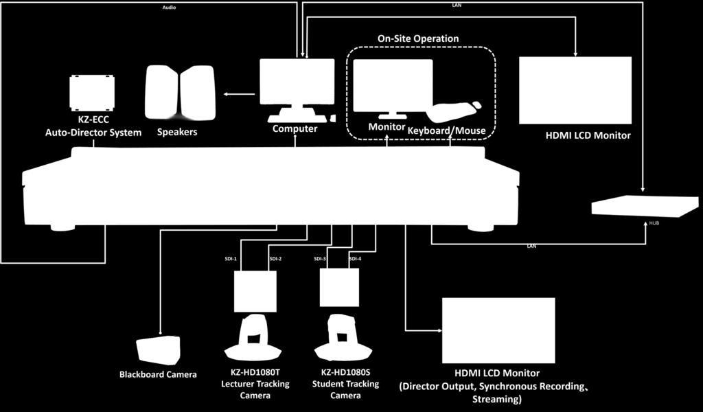
8 3. Connections 8

9 4. Structure 9
10 5. Configurations 5.1. Before Configuration Prepare the following devices before configuration: 1 LAN Cables and Router 2 Power cable of NP6000, VGA and HDMI cables, Audio RCA input and output cables, SDI cables P23/30 cameras, computer, RCA Speakers, Monitoring earphone. 4 Display requirements: VGA and HDMI ports embedded; 1920X1080 HD resolution 5.2. Cables 1 All cables, including SDI, Audio, VGA, DVI, LAN, IO/RS485 control, power, and USB mouse, should be connected to KZ-NP Make sure power supply is correctly connected and press the Power button to turn on KZ-NP6000. Please wait for 30 seconds and enter the director interface. Then, you will be able to operate the whole system. Note: A. The VGA output refers to system interface of director, users can operate via USB mouse which should be connected to the USB port of NP6000. B. The HDMI-out refers to broadcasting streams (PGM1 or PGM2) C. The default static IP is
11 6. Functionalities and Operation There are 5 Modules in Main Interface:Monitoring Module, Input Channels, PTZ, Director Functionalities, and System Functionalities. 11

12 6.1. Main Interface Startup Screen After connected to the power supply and then press the power button, the connected monitors with VGA and HDMI will show the startup screen at the same time. Startup screen graphic can be customized, such a function is located at SYSTEM SETTINGS / SYSTEM INFO / ENGINEERING MODE. The format of the startup screen graphic should be in JPG and at 1024*768 pixels resolution. The size of the graphic should not above 128KB. Graphic of the system interface should be in GIF format and at 200*100 pixels resolution. Please note that the graphic of the interface should be at 72 DPI. While customizing the graphics, the file names should not content Chinese or symbols Main Interface It will take around 20 seconds to start up KZ-NP6000 and then you will be able to enter Main Interface directly. At the same time, there will be a loading message shown up and then you can start to operate the main interface. There are 5 Modules in Main Interface: 1. Monitoring Module, 2. Input Channels, 3. PTZ 4. Director Functionalities 5. System Functionalities. 12


13 6.2. Monitoring Interface There are 4 modules in Monitoring Interface; Movie Mode: PGM and PVW Channels Res Mode: PGM and PGM Channels, Audio Bar, Hot Keys of PGM and PGM2. Movie Mode: PGM and PVW Channels Res Mode: PGM and PGM2 Channels A. Both Single and Res modes are in Movie format. These two modes support layer superimposition functionalities: PIP, conversation mode, 2/3/4/6 displays and so on. There are PGM (Live streaming video) and PVW (Stream Preview) channels. There are PGM and PGM2 channels in Res Mode. B. When in Auto Director module, both Single and Res modes only support PGM image auto switching. When the Res Mode is in Manual Director mode, manual display switch is supported (HDMI-Out output), which can switch the video streams from PGM to PGM2 by clicking Director Output button. 13
14 C. In Movie Mode, user can manually select the PGM channels. The default channel is PGM and click the list to select PGM2 to do manual director. D. Audio Bar can be shown in both Single and Res modes, which are two lines located at between PGM and PVW in Movie mode, PGM and PGM2 in Res mode. The main function is to adjust the volume of the audio output by clicking the icon to adjust, turn on, or turn off the audio output. E. In PG and PGM2 Channels, users can click the hot keys to execute following actions: TS Streaming RTMP Streaming Start Local Recording Paulse Local Recording Stop Local Recording Note: The server IP or TS broadcasting IP should be set up first in Recording Settings unit before proceed live streaming. F. The video image of PGM can be replaced by the video image of PVW by clicking PVW area two times. Multiple layers combination are supported in PVW, PGM, and PGM2. First of all, users should select PGM, PGM2, or PVW channel. Then select the layout and select the video inputs to combine according to the selected layout style. 14

15 6.3. Video Inputs Channel There are 3 parts of Video Inputs Channel: Local Video Display, Local Playback Channel, and Distanced Videos Display Channel. There are 22 channels in each KZ-NP6000. PGM2, there are more 18 video channels. Except 4 channels occupied by PGM, PVW, and The first page of 7 video channels indicates local video inputs including local playback channel. The following chart refers to the default inputs identifications. SDI 1 Lecturer Close-Up SDI 5 Blackboard Writing Close-Up SDI 2 Lecturer Panorama DVI-I x 2 Refers to DVI-I inputs SDI 3 SDI 4 Student Panorama Student Close-Up Despite of 7 occupied inputs, each KZ-NP6000 can be connected to another 11 distanced video and audio sources. The distanced sources can be switched to PGM, PVW, and even PGM2 to be live streams and recorded locally. Such functions should be based upon 2 or more KZ-NP6000 systems installed and connected in a network Channel Interface A. Full Screen: Click button to enlarge a certain video channel to full screen in main interface. B. Channel Titles: The default titles of video inputs channels are; 1 st Channel Lecturer Panorama 5 th Channel Blackboard Writing Close-Up 2 nd Channel Lecturer Close-Up 6 th Channel Lecturer s Computer / Laptop (VGA or HDMI) 3 rd Channel Student Panorama 7 th Channel Local Video Playback 15
16 4 th Channel Student Close-Up Each Channel title is editable, however, we suggest not to change these titles in case of confusion. Note: When in Live broadcasting or recording status, the certain PGM channel will be shown in RED. If in preview status, the certain PVW channel will be shown in GREEN. C. PTZ Control: If the connected camera is a PTZ camera, then click button at the top of the certain channel to activate PTZ control. Then, users can take advantage of PTZ control functionality in Channel Settings area. Just click the certain channel you want to do PTZ control, then, the function is active. The default active PTZ control channels are Lecturer Close-Up and Student Close-Up channels. D. Local Playback: The 7 th channel named FileVideo-1 refers to local playback channel. Click button at the up-right corner of this channel to enter channel configuration section. Click Select Files to select a file in mp4 format from HDD or USB Drive. Click Apply and OK after done the selection. Click to play the certain video clip and click to stop playing the video clip. Local playback sources can be 16
17 switched to PGM Live broadcasting channel. E. Audio Control: Click button at the top of each channel to turn on / off the audio. Local and distanced audio sources are both supported Channel Configurations There is a button at the up-right of each channel, which is for channel configurations including Channel Settings, PTZ Settings, Image settings, and Encoding Settings Channel Settings A. Chn Name: Chinese and English languages are supported. The number of digits are 6 digits for each channel name. B. Source: Input source. i.e. Lecturer Panorama SDI 1 indicates the source of Lecturer Panorama is from SDI 1. C. Video Format: The format and bitrate of the source, i.e P25 D. Disp Mode: Ratio or Full Screen. If the video image in PGM is not in full screen, then, 17

18 it can be edited in this section. E. Enable PTZ: When PTZ control is activated, there will be a button at the left buttom of the certain channel. The defaults are Lecturer Close-Up and Student Close-Up channels. F. DVI-I Input Source: There will be AUTO, HDMI, and VGA sources to be selected in DVI-I settings. G. Recycle: In FileVideo_1 channel, there is a function named Recycle which indicates to continuously play the video clip selected from USB drive or local HDD. 18

19 PTZ A. Enable PTZ:To activate PTZ by checking the box. B. Protocol: VISCA PELCO-P and PELCO-D protocols are supported C. COM: RS48 and RS232 are supported D. Baud Rate: 2400, 4800, and 9600 are supported for different PTZ cameras E. Address Code: The address code should be the same as that in PTZ settings. 1 for Lecturer Close-Up; 2 for Student Close-Up. F. Speed: The speed of PTZ G. Preset: To set up the presets from 1 to 8 presets, also including Big Close-Up, Close-Up, Vista, Medium Shot, Close Shot and so on. The default presets are; 11 Big Close-Up 14 Medium Shot 12 Close-Up 15 Vista 13 Close Shot H. PTZ Operation: Click,,, to control Up, Down, Left, and Right direction of the camera. 19

20 Zoom: + and - indicate to Zoom in or Zoom out of the lens. Focus: + and - indicate to focus on distanced and near object. Iris: + and - indicate to transfer Large and Small aperture Note: To make sure the PTZ control will be working accordingly, the connections of cameras to KZ-NP6000 should be correct. Also, the PTZ protocol, COM, and Address Code should be identical with camera settings Picture As shown the above, this section is to configure Brightness, Contract, Chroma, and Saturation of the video quality. Normally, there is no needs to do these settings. 20

21 Encode 說明 : A. Resolution: a. Major Code: 1920*1080, 1600*900, 1280*720, and 960*540 b. Minor Code: 960*540, 640*360, 480*270, 720*576, and 352*288 Note: When in PGM with multiple sources and video images, the channel recording will be based upon this resolution to proceed recording. B. Codec: H.264 is the main format C. Bitrate: It can be adjusted from 48Kbps to 20Mbps, and the default is 5120Kbps for major code, 1024Kbps is the bitrate of the minor code. D. Quality:from 0 to 5 levels, 0 indicates the best quality. E. FPS: from 10 to 60 adjustable, the default is 25. F. GOP: The Intervals of between FPS, the default is 30S. 21

22 6.4. PTZ Control PTZ Control A. PTZ Operation: Click,,, to control Up, Down, Left, and Right direction of the camera. Zoom: + and - indicate to Zoom in or Zoom out of the lens. Focus: + and - indicate to focus on distanced and near object. Iris: + and - indicate to transfer Large and Small aperture To set up the presets from 1 to 8 presets, also including Big Close-Up, Close-Up, Vista, Medium Shot, Close Shot and so on. 11 Big Close-Up 14 Medium Shot 12 Close-Up 15 Vista 13 Close Shot After done these settings, users can click,,,, these buttons to switch Big Close-Up (11), Close-Up (12), Close Shot (13), Medium Shot (14), and Vista (15) 22
 to")
23 presets Meeting Control Distanced Interaction Meeting control refers to connect distanced KZ-NP6000 system and proceed the interaction between two systems. When the lecturer classroom is holding a teaching activity, the distanced classroom can get the video and audio signals of the lecturer classroom by adding a new distanced device (KZ-NP6000) to proceed synchronous learning / meeting. As shown above, when more than 2 KZ-NP6000 systems are in the same intranet network, the left side will display all devices automatically when clicking Add button. Also, users can manually add devices from Internet. However, the IP address of the devices in Internet should be mirrored by routers and the mirror port should be Click button to add devices that system has searched in Intranet and Internet. 23


24 While select the desired distanced channels, please press right button of the mouse and select all channels or certain channels. The selected channels will be shown in the Input Channels. Note: The distanced channels will be located the second page of input channels. As shown above, users can adjust the volume of the selected distanced inputs. In distanced input channels, the audio signals in PGM or PGM2 can be played to local speakers Director There are 8 parts of Director mode: A. Segmentation / Transform B. Subtitle / Sound C. Corner / OSD Info / Time D. State E. Insert Titles / Endings F. Full Auto / Semi Auto / Manual G. Movie / Res Mode: Movie Mode or Resource Mode H. Single / Dual Mode I. Quick Start 24


25 Segmentation / Transform 1 Segmentation: Users can select layouts for PGM, PVW, and PGM2 Channels. There are Single Display, Dual Display, Picture in Picture, Conversation Display, 3 / 4 / 6 Displays and even V1 / V2 / V3 customized layouts. Movie Mode 1 and Movie Mode 2 in the settings of Quick Start should be the recording of PGM and PGM 2. If the layouts of these 2 channels are multiple displays, then, the format of recorded videos will be one stream with multiple layouts. 2 Transform: This is the settings of special effects of layout switch. There are; A. Wipe; B. Cover; C. Push; D. other (Stretch, Dissolve, PiP). Layout switch can be in 4 directions and 4 diagonals to proceed the layout switch. Speed indicates how fast the switch will be, the bigger value of the Speed, the slower the layout switch will be. 25

26 Subtitles / Sound A. Subtitles: Click at the up-right of this unit to enter settings section. Users can edit and import subtitles here. Subtitles can be inserted to PVW channel to preview. If there is no problems with PVW channel, then the subtitles can be inserted to PGM, the live broadcasting channel. After inserted subtitles, the button will be changed into Cancel. Users can click PGM Cancel or PVW Cancel to hide subtitles. Only one row of subtitle is allowed and the following subtitles will replace the former ones. 26


27 B. Sound The volume of PGM streaming, PGM recording, and PGM2 streaming, and PGM2 recording can be adjusted in this section. It can be mute or unmute by clicking the buttons at the bottom of this area Corner / OSD Info / Time / Add OSD A. Corner Users can insert corner logos in PGM / PVW or PGM2. The maximum numbers of corner logos are 8. Here below is the chart of positions. NO. Position NO. Position 1 Up-Left 3 Down-Left 2 Up-Right 4 Down-Right The positions of No. 5 ~ No.8 are the same as the above. However, users can configure each position by clicking button. Also, the graphic can be replaced by users. The best solution of the corner logo is 200*100 pixels in PNG format. 27

28 B. OSD Info OSD Info refers to the course information. Users can edit course title, lecturer s name, and date here. By clicking Insert button, OSD will be shown up at the down-right corner. Like the settings of corner logo, users can configure Uppercase, Color of the letters, and Background color of the OSD by clicking button. 28
.")


29 C. Time / Add OSD Users can insert Time in PGM and PVW Channels (Movie Mode) and PGM, PVW, and PGM2 (Res Mode). However, if users want to insert more information to channels, just edit in Add OSD section State There are 2 indications in this unit, Movie mode and Movie mode 2. Movie Mode 2 refers to PGM2 channel in Res Mode. When Movie Mode is in broadcasting and recording status, then, there will be shown LIVE and REC in RED color. The display of Movie Mode 2 is the same as Movie mode. 29

30 Users can do the quick settings by clicking button at the up-right corner in this unit Titles / Endings The format of titles and trailers should be in MP4 format. These video clips can be the recorded files or from USB drive or extended HDD. Save the path by clicking OK button. After clicking Insert, the title will be shown up before the live broadcasting. While the broadcasting is about to end, just click Insert button to insert the trailer and then the video clip will be shown up at the end of the live broadcasting. 30
31 Manual Director / Auto Director Manual Director: Users can switch layouts and control cameras during the live broadcasting. When clicking twice of left button of the mouse on PVW channel, the image of PGM will be replaced by that of PVW. Besides, users can also change the image of PGM directly. Click PGM channel and select the desired layout first. Then select the certain video inputs from the video inputs channel. When switched to Manual Director, the default setting is to disable tracking camera or tracking system. If users want to activate the tracking functionality, just click the right button and it will be working. Note: The commend codes of auto tracking cameras or tracking systems are identical with commends of KZ-NP6000. Users can modify the commend codes of auto tracking in Recording / Auto Tracking / Lecturer or Student Close-Up Semi Auto: In this mode, the auto-tracking functionality is activated, but not switch automatically. Users have to switch the layout or image manually Full Auto This function can proceed image switching based on the strategy automatically. While in Full Auto status, the manual operation of PTZ cameras will be disabled. There are 8 indicators at the right side of the button. If the indicator shown in RED, then it refers to the certain video inputs have been triggered and active. B will be always in RED. Here below is the chart of the indicators. 31
32 A Lecturer Panorama E Blackboard Writing Camera A B Lecturer Close-Up F VGA Input A C Student Panorama G Blackboard Writing Camera B D Student Close-Up H VGA Input B Movie Mode / Res Mode Both Movie Mode and Res Mode are in movie streaming. All PGM, PGM2 and PVW in Movie mode and Res mode can proceed layout switch. There are hot keys under PGM (Movie Mode) and PGM 2 (Res Mode) channels including TS broadcasting, RTMP broadcasting, REC Start / Pause / Stop, Director Output, and Channel Switch. A. Movie Mode: There are PGM (Live Broadcasting) and PVW (Preview) channels. The default live broadcasting channel in Movie Mode is PGM but can be changed to PGM2 via PVW to proceed the switch. B. Res Mode: There are PGM and PGM 2 channels in this mode. can output different director image to HD monitor. When in Manual Director, users There is no PVW (Preview) in Res Mode. All layout switch will be in manual control. C. If the layout is included PGM and PGM2 channels, then the recording will be single file of multiple screens. D. If users want to record the resources separately, then please visit Record settings/record/sub-channel Record section to select the desired channels to be recorded. Then, select Resources Record in Quick Start configuration. Click Quick Start button in the main interface to start resources recording. 32
33 System Functionalities There are 5 modules in this unit: A. Quick Start B. Recording and Broadcasting Settings C. System Configuration D. File Management E. Log-in Settings Quick Start This is a hot key to proceed one-click start functionality after all desired settings have been set up, such as Movie mode recording and Live broadcasting; Movie mode 2 recording and Live broadcasting; Auto Director; Resources Mode Recording Recording and Broadcasting Settings This unit mainly takes care of major settings of this system, such setting units are Boot, Encoding, Audio, Recording, Time Recording, RTMP Streaming, TS Streaming, Auto-Tracking, Strategy, and Network of Tracking Machine. 33


34 Boot This unit mainly configures Quick Start button functions. Users can define what functions should be activated by clicking Quick Start button. 34

35 Encoding The functions of this unit is quite different from Channel Settings in Channel Settings is to configure the resolutions of the image in the channel. Encoding settings are to configure the configurations of PGM and PGM 2 channels in Movie mode in order to adjust the resolutions of live broadcasting channels in recording mode. A. Resolution: Major Codes: 1920*1080, 1280*720, 960*540 Minor Codes: 960*540, 640*360, 480*270, 720*576, 352*288 B. Codec: adopts H.264 video compression format C. BitRate: from 48Kbps to 20Mbps adjustable. The default BitRate of Major stream is 4000Kbps; the Minor Stream is 400Kbps. D. FPS: from 10 to 60 FPS adjustable. The default is 25 FPS E. GOP: duration between 1 FPS. The default is 30S 35

36 Audio Users can configure the audio quality of the video Recording 36
37 A. Segmentation: Refers to the duration of time while packing and saving recorded files. The default is 60 minutes. However, users can change the settings according to their requirements. 50~60 minutes of a recorded file duration is recommended. B. Format: MP4 is the only default format. C. Movie Record: Refers to the root folder of recorded videos. Users can change the default folders of the recorded videos to a USB drive or an extended HDD. In Movie mode, the default path of the recorded files is in PGM folder. In Movie mode 2, the default folder is PGM2 folder. D. Res Record: Refers to record the input resources to individual files. While been checked, the video resources will be recorded when users click Quick Start to start recording in the main interface. Due to the limit of CPU in the system, we do not recommend to record more than 4 resource videos at the same time in case of lost of frames or bad quality of recorded file. 37

38 Time Record (Recording Schedules Settings) Users can set up 10 recording schedules in this system. Also, users can copy the detailed information to other week dates. Note: All settings details should be completely copied to specific week dates to activate the recording schedules. 38

39 RTMP Stream This unit adopts standard RTMP protocol. The streaming way will be in COMMON which indicates to deliver live streams to the streaming server with RTMP support. The settings of streaming will be PGM streams in Movie mode and PGM2 streams in Movie mode 2. There are Main Stream and Sub-Stream in each mode. The values of streams BitRate can be adjusted according to the bandwidth status. It is between 48Kbps to 20Mbps. The default BitRate of main stream is 4000Kbps and Sub-Stream is 400Kbps. 39
40 Quick Start Setting Users can configure the active functions in this unit. Just select the desired functions, e.g. Movie Record, Movie 2 Record, Auto Conducting, Movie Stream, Movie Stream 2, and RES Record. RES Record should be selected in Recording / RES Mode Note: The Quick Start button in main interface can be connected to Director Switch. There is a Quick Start button in most Director Switch units. Users can use Director keyboard to proceed director operations after having set up Quick Start functionality. 40

41 TS Stream TS Streaming is supported in this system. However, TS streaming only available in intranet. There is no need to install RTMP streaming server or software. It only requires media players that supports network streaming such as VLC, Storm, or other players. Just input the specific streaming path and will be able to view the live streams directly. TS single streaming adopts TCP Network communications protocols and it will be working after the viewers requests. The operation processes are; 1. Select the stream (Main or Sub Stream) 2. Streaming port setting 3. Back to the main interface and click in PGM channel to start live streaming 4. Input tcp://system IP:streaming port and will be able to view the live stream TS Group streaming adopts UDP network communications protocol without requested by viewers (running a media player.) Just select the identical BitRate and port, then click button to start streaming. The processes are the same as the above. The default streaming IP address is The format of the streaming is rtp:// :steam port and users will be able to view the live stream directly. 41

42 Note: The differences between Group Streaming and Single Streaming is that in single streaming, viewers should directly communicate with the system and then to be able to view the live stream. The number of concurrent viewers is limited. Group Streaming requires intranet with routing support. Normally, the default Group Streaming IP is When Group Streaming is active, the live stream will be broadcasted automatically. While users launch the media player and type in the Group Streaming address, then they will be able to view the live stream. A Group Streaming supports 253 concurrent viewers Auto Track Users can configure the commends of recording system, lecturer camera, student camera, blackboard writing, and VGA desktop interface. The interface code and commends should be identical with settings of recording system and tracking cameras. There are 3 options, I/O, LAN, and Serial Ports to configure lecturer panorama, lecturer close-up, student panorama, student close-up, and blackboard writing interface. 1 If the communications ports are RS232 or RS485 serial ports, then users can configure in this section. If RS232 is the connection ports, then users should select COM2 or COM3. If 42
43 RS485 is the connection ports, just select RS485. Normally, the carry value of commends of serial ports are in 16 and they must be identical with those of tracking cameras or recording system. In this way, the tracking cameras or recording system will be able to work normally. 2 If I/O connection is the communications connection method, then please select the connection type in I/O. There are 8 options in I/O connections, from I/O1 to I/O8. Users can do the configuration based upon the physical interface. If the connection style is I/O, then there is no need to input any commend but to activate certain action with electricity triggering to achieve the desired actions. 3 If the connection of cameras and the main system is via network, then please select Network. There are continuous and one-time modes. Continuous mode refers to switch right after been triggered and switch to another scenario after certain time. One-time mode refers to be triggered one time and switch to certain image and keep switching to a certain senerio. 4 VGA (Lecturer s computer / laptop) signal switch 5 Users can select Network and Auto Detect to proceed image switch. When selecting Network, there should be a software installed into lecturer s computer / laptop and configured an identical IP and connection port (9999) with recording system. If there is any action in lecturer s computer / laptop, the signal will be transmitted to the recording system via network to trigger image switch. When Auto Detect is selected, there is no need to install any software into lecturer s computer / laptop. If there is any action on lecturer s computer / laptop, then the image switch will be triggered automatically. VGA delay can be modified based on users requirements. The default value of VGA delay is 10S. The above 2 settings will be able to be repeated after the first time activation. Which means that when the first action has been triggered, then after 5 seconds, the same action is triggered again. The VGA delay will be counted from the beginning. If there are 2 blackboard writing and 2 VGA have been set up at Network and continuous mode. Users should manually configure the commend codes via the software and the codes which should be identical with blackboard writing and VGA detection codes. Note: The commend codes of blackboard writing and VGA detection are the first 2 codes. The following codes of blackboard writing and VGA detection are for 1+6 and 2+4 positions (2 43


44 blackboard writing and 2 VGA detection) Strategy Click Modify and input the default password 1 to enter the advanced strategy configuration. There is column of switch strategies and users can modify if necessary. A. Alarm Status Current Status: B. It refers to the working status of all active devices. From left to right is the list of devices, e.g refers to the list of devices Number Devices Lecturer Lecturer Student Student VGA Input A VGA Input B Blackboard Blackboard Panorama Close-Up Panorama Close-Up (Computer (Computer Writing A Writing B Camera Camera Camera Camera Desktop) Desktop) 0 refers to no signal; 1 refers to active signal 44


45 C. Actions Transition Effects: Users can configure the transition effects from Director to PGM image switch. There are 12 default layouts for selection. Besides, users can edit the layout styles of U1, U2, and U3. D. Actions Switch Styles: The transition styles of PGM, e.g. W refers to Wipe style There are 8 directions of each transition switch. Note: AB icon in other refers to Fade in / out effect, which is much popular. 45
 The maximum number of camera")
46 E. Actions Camera Selection: Users can select the devices to switch. Each letter (from A to F) represents one device. A Lecturer Panorama Camera D Student Close-Up Camera B Lecturer Close-Up Camera E Blackboard Writing C Student Panorama Camera F VGA input (Lecturer s Computer / Laptop) The maximum number of camera selection is 3 cameras. The default number is 2 cameras. As shown in the above graphic. The switch actions of are; When the signals of lecturer close-up camera, student close-up camera, Blackboard Writing A, and VGA input A have been detected, the action descriptions are; The first switch is E (Blackboard Writing) in single display effect. There is no transition effect in this action. The delay duration is 0 (The delay duration refers to the time to change next action.) Then, it will switch to action 2. Action 2 is E (Blackboard) and Student Close-Up camera image in PiP display mode. Note: If the camera selection is blank in the action list, which means that it will stop switching after been switched to the last action. If users want to modify and add new switch strategy, just select the certain strategy row and click twice of the left button of the mouse. Then the certain row will be shown on the 3 rd row. Users can modify current switch actions of transition effects, cameras, duration of delay and so on. The default actions has already been set up for normal operation. Please do not modify if there is no additional requirements. If users want to revert the system to the default, just select to revert the default value of the system in SYSTEM INFO of SYSTEM SETTINGS 46

47 System Configurations There are 7 sections in this unit; A. User Management B. Disk Management C. Network Settings E. Dual Graphic Cards Settings F. Control G. System Info D. Network Test User Management Users can configure the permissions, add new users, and change passwords. This system has been set up for all users and there is no need to log in. The functionalities of this unit is disabled. 47

48 Disk Management In this section, users can view the details of the connecting storage drives. Also, users can format and unload storage drives. Users can figure out the types, models, and the status of the storage drives. If a new storage drive is not formatted yet, there will be no storage data in the list until the new drive has been formatted. There are repeat recording (Cover) and stop recording when the drive is full functions. NTFS and EXT4 formatting functionalities are supported. EXT4 is for Linux system not for Windows system. It requires special tools to proceed disk management if the storage drive is connected to a Windows system. KZ-NP6000 is compatible with SMB protocol and recorded video sharing in intranet SAMBA protocol. In practice, users can copy the recorded videos by logging into KZ-NP6000. It is faster than that by USB drive. FTP distanced download is supported in KZ-NP6000. Users can proceed distanced downloading by typing ftp://ip address of KZ-NP6000. In this way, there is no need to copy files on site. 48

49 Network Configuration There is a 1G LAN port at the rear of KZ-NP6000. In this section, the default setting is DHCP. Users can configure the network IP and other information by unchecked DHCP box. After having got the IP address of KZ-NP6000, users can proceed network update by a tool. Also, users can set up KZ-NP6000 as a mirror sharing device. If mirror sharing is connecting to internet by 554 port, users can view RTSP live streams. If mirror sharing to Internet by port, users can proceed the distanced director and online class monitoring. Meanwhile, if more than 2 KZ-NP6000 have been installed, then, it will be able to do online interaction among multiple KZ-NP6000 systems to import distanced video images and audio to local channels. 49


50 Network Test This section is mainly for network pinging. Users can figure out the packing loose and the information of network delay. Please note that the IP address should be in the same Intranet network. Such a function is normally used to do RTMP streaming server test and the quality of network connection of a computer and KZ-NP Dual Graphic Cards Settings 50

51 KZ-NP6000 is embedded Dual-Graphic outputs. Graphic Card 1 represents local director image (VGA output). Graphic Card 2 represents PGM live broadcasting image (HDMI output). The identical output ports at the rear of KZ-NP6000 are Graphic Card 1 for VGA out and Graphic Card 2 for HDMI out. Hardware interface cannot be modified, but it can be changed in software system, e.g. the output of Graphic Card 1 will be HDMI instead of VGA and the output of Graphic Card 2 will be VGA instead of HDMI. Then the hardware interface will be VGA output for PGM live streaming and HDMI output for local director image Control This section is the setting of the central control system and KZ-NP6000. The communications interfaces are compatible with RS485 and RS232. If connected to RS232 of KZ-NP6000, it is supported to DB9 I and DB9 II ports. The hotkey codes of START / PAUSE / STOP recording should be identical with those of the certain central control system. 51

52 System Info A. Version Info: To view the ID, software version, ROM, and Released Date of KZ-NP6000 B. Language: Simplified Chinese and English are supported C. Date format: YYYY-MM-DD and MM-DD-YYYY are supported D. Time settings: Manual settings of the Date and NTP E. Name of the system F. Reset: to reset the default settings G. Update: not active. It requires a update tool in Intranet. H. Shutdown: not active I. Restart: to reboot KZ-NP6000 J. Screen Test: to discover if there is any flaw on the display screen K. Engineering: After inputting the default password 1, users can change the system logo and interface logo. The format of system logo should be in JPG format with 1024*768 pixels and not be more than 128KB. Interface logo should be in GIF format with 200*100 pixels. L. Import / Export: Users can import and export all settings to / from a USB drive or local HDD. It is more convenient for users to update or import to a new sytem. 52

53 File Management Users can search, delete, copy, paste, rename files in this unit Log in Settings (not available in this version) 53
54 In User Management section, there are Administrator and User roles. An administrator and operate and configure more functionalities of KZ-NP6000. Also, the administrator can define and authorize what functionalities that a user role can operate or configure. When the log-in page shown up, all users should log into the system and proceed what they have been authorized. In this version of KZ-NP6000, this function is disabled. 54
55 7. FAQ 7.1. Could not control the PTZ camera Please make sure the connections of control cable and KZ-NP6000 is correct. Make sure Enable PTZ is checked in Channel Setting unit. Make sure the protocol, transmission rate, and IP address are identical with the PTZ camera 7.2. VGA input (Lecturer s Computer / Laptop) is blank Please examine the VGA cable is correctly and well connected to the computer and KZ-NP6000 Please change the resolution of computer into 1024*768 and see if there is a image shown up. Then, please adjust the resolution to an appropriate resolution There are black labels or the image is not in full screen Make sure Full Screen is selected in Display Style in Channel Settings Make sure the resolution ratio of the computer is 16: When in Auto Director mode, the VGA input cannot be switch automatically Please check whether DHCP in System Configurations / Network Configuration / NET2 is enabled or not. If DHCP is enabled, the IP address will be changed randomly, which will cause such a situation. So, please set up the IP addresses of KZ-NP6000 and the computer to be in the same network. Please make sure the auto switch software is well running or not. There will be a icon in the work bar of the computer. Then make sure the IP address is identical with that in KZ-NP Screens of Lecturer or Student are blank Examine the SDI cables are well connected and the cameras are powered. Modify the input resolutions to 1080P25 or 1080P PGM image cannot be switched when in Auto Director mode Make sure the commends have been well transmitted. If so, there will be a red light on at the right side of the buttons. If there is no red lights on, then, please check the control cables are well connected. Make sure the settings and configurations equipment are identical. 55
56 7.7. The audio of the recorded video is broken and sonic boom Examine the volume in Audio Input section has been changed. If the volume is too loud, then the sound of the video will be broken or sonic boom. If so, please adjust the volume to the softest. Normally, 50% volume will be fine. If the volume has not been changed, then please check if the audio input connection is well connected and the volume of mixer is too loud or not. If there is no problems with such settings and connections, the system might be out of order and please contact your provider to fix it The recorded videos cannot be played when copied to USB drive or moved to extended HDD The USB drive or extended HDD cannot be pulled out. It should be unloaded in Disk Management section, or, the videos cannot be played normally. Examine the media player is supported H.264 encoding and decoding. (Media Player supported H VLC, STORM, and so on) There is no response after pressing START RECODING or Quick Start button Examine the connection of Central Control system and KZ-NP6000 is well connected. Examine the settings of the serial ports and the commend codes are correct. Make sure Intelligent Mode settings are active in Recording / Quick Start Live Streams are blurred or not smooth Please examine the sub-stream is selected or not in Recording / Stream / Movie Mode. If sub-stream is selected, users can adjust the Bit Rate of the sub-stream to bigger a Bit Rate if the bandwidth is good condition. If the major stream is selected, then, it might be the bandwidth quality is bad. Please consult your IT department to adjust the bandwidth or adjust the Bit Rate of the major stream to an appropriate one. 56
57 8. Limited Warranty For a period of time beginning on the date of purchase of the applicable product and extending as set forth in the Warranty Period of Konze Product Purchased section of the warranty card, Konze System Technology Co., Ltd. ( KONZESYS ) warrants that the applicable product ( Product ) substantially conforms to KONZESYS s documentation for the product and that its manufacture and components are free of defects in material and workmanship under normal use. You as used in this agreement means you individually or the business entity on whose behalf you use or install the product, as applicable. This limited warranty extends only to you as the original purchaser. Except for the foregoing, the Product is provided AS IS. In no event does KONZESYS warrant that You will be able to operate the Product without problems or interruptions, or that the Product is suitable you re your purposes. Your exclusive remedy and the entire liability of KONZESYS under this paragraph shall be, at KONZESYS s option, the repair or replacement of the Product with the same or a comparable product. This warranty does not apply to (a) any Product on which the serial number has been defaced, modified, or removed, or (b) cartons, cases, batteries, cabinets, tapes, or accessories used with this product. This warranty does not apply to any Product that has suffered damage, deterioration or malfunction due to (a) accident, abuse, misuse, neglect, fire, water, lightning, or other acts of nature, commercial or industrial use, unauthorized product modification or failure to follow instructions included with the Product, (b) misapplication of service by someone other than the manufacturer s representative, (c) any shipment damages (such claims must be made with the carrier), or (d) any other causes that do not relate to a Product defect. The Warranty Period of any repaired or replaced Product shall be the longer of (a) the original Warranty Period or (b) thirty (30) days from the date of delivery of the repaired or replaced product. 9. Limitations of Warranty KONZESYS makes no warranties to any third party. You are responsible for all claims, damages, settlements, expenses, and attorneys fees with respect to claims made against you as a result of your use or misuse of the Product. This warranty applies only if the Product is installed, operated, maintained, and used in accordance with KONZESYS specifications. Specifically, the warranties do not extend to any failure caused by (i) accident, unusual physical, electrical, or electromagnetic stress, neglect or misuse, (ii) fluctuations in electrical power beyond KONZESYS specifications, (iii) use of the Product with any accessories or options not furnished by KONZESYS or its authorized agents, or (iv) installation, alteration, or repair of the Product by anyone other than KONZESYS or its authorized agents. 10. Disclaimer of Warranty Except as expressly provided otherwise herein and to the maximum extent permitted by applicable law, KONZESYS disclaims all other warranties with respect to the product, whether express, implied, statutory or otherwise, including without limitation, satisfactory quality, course of dealing, trade usage or practice or the implied warranties of merchantability, fitness for a particular purpose or non-infringement of third party rights. 57
58 11. Limitation of Liability In no event shall KONZESYS be liable for indirect, incidental, special, exemplary, punitive, or consequential damages of any nature including, but not limited to, loss of profits, data, revenue, production, or use, business interruption, or procurement of substitute goods or services arising out of or in connection with this limited warranty, or the use or performance of any product, whether based on contract or tort, including negligence, or any other legal theory, even if KONZESYS has advised of the possibility of such damages. KONZESYS s total, aggregate liability for damages of any nature, regardless of form of action, shall in no event exceed the amount paid by you to KONZESYS for the specific product upon which liability is based. 12. Governing Law and Your Rights This warranty gives you specific legal rights; you may also have other rights granted under state law. These rights vary from state to state. 58
DS-7200HFI-SL Series DVR. Technical Specification
 DS-7200HFI-SL Series DVR Technical Specification Notices The information in this documentation is subject to change without notice and does not represent any commitment on behalf of HIKVISION. HIKVISION
Digital Video Recorder
 Digital Video Recorder Quick Operation Guide UD.6L0202B0067A02 Thank you for purchasing our product. If there is any question or request, please do not hesitate to contact dealer. This manual is applicable
EVD-L04/100A1-960, EVD-L08/200A1-960 and. EVD-L16/400A1-960 DVRs. Quick Operation Guide
 EVD-L04/100A1-960, EVD-L08/200A1-960 and EVD-L16/400A1-960 DVRs Quick Operation Guide Thank you for purchasing our product. If there is any question or request, please do not hesitate to contact dealer.
EVD-L04/100A1-960 EVD-L08/200A1-960 EVD-L16/400A1-960
 EVD-L04/100A1-960 EVD-L08/200A1-960 EVD-L16/400A1-960 www.eurovideo-cctv.com Main Features Main stream supports encoding at up to WD1 resolution in real time and sub stream at CIF/QCIF resolution. Simultaneous
DS-7204/7208/7216HVI-ST Series DVR Technical Manual
 DS-7204/7208/7216HVI-ST Series DVR Technical Manual Notices The information in this documentation is subject to change without notice and does not represent any commitment on behalf of HIKVISION. HIKVISION
VSP 198CVS Quick Start
 VIEWSIZE THE WORLD VSP 198CVS Quick Start Max 2048 1152@60Hz/2560 1152 50Hz input/output resolution User customize output resolution 3G/HD/SD-SDI input Multiple cascade mapping for super resolution DVI
DS-7200HVI/HFI-SH Series DVR Quick Operation Guide
 DS-7200HVI/HFI-SH Series DVR Quick Operation Guide UD.6L0202B0019A01 Thank you for purchasing our product. If there is any question or request, please do not hesitate to contact dealer. This manual is
Quick Operation Guide of LTN7700/7600 Series NVR
 Quick Operation Guide of LTN7700/7600 Series NVR UD.6L0202B0042A02 Thank you for purchasing our product. If there is any question or request, please do not hesitate to contact dealer. This manual is applicable
SuperSpeed USB 3.0 to HDMI Audio Video Adapter for Windows & Mac up to 2048x1152 / 1920x1200
 SuperSpeed USB 3.0 to HDMI Audio Video Adapter for Windows & Mac up to 2048x1152 / 1920x1200 Copyright and Trademarks Specifications are subject to change without notice. Cable Matters is a registered
SCode V3.5.1 (SP-601 and MP-6010) Digital Video Network Surveillance System
 Digital Video Network Surveillance System") V3.5.1 (SP-601 and MP-6010) Digital Video Network Surveillance System Core Technologies Image Compression MPEG4. It supports high compression rate with good image quality and reduces the requirement of
V3.5.1 (SP-601 and MP-6010) Digital Video Network Surveillance System Core Technologies Image Compression MPEG4. It supports high compression rate with good image quality and reduces the requirement of
SCode V3.5.1 (SP-501 and MP-9200) Digital Video Network Surveillance System
 Digital Video Network Surveillance System") V3.5.1 (SP-501 and MP-9200) Digital Video Network Surveillance System Core Technologies Image Compression MPEG4. It supports high compression rate with good image quality and reduces the requirement of
V3.5.1 (SP-501 and MP-9200) Digital Video Network Surveillance System Core Technologies Image Compression MPEG4. It supports high compression rate with good image quality and reduces the requirement of
AT-HDPIX. Users Manual
 AT-HDPIX Users Manual Contents 1. Installation...2 2. Introduction:...3 3. Features:...3 4. PC Requirements:...3 4.1 Mac Requirements:...3 5.0 Updates:...4 5.1 Screen Resolution:...4 5.2 Color Quality:...5
DS-7200HVI-ST/RW Series DVR. Technical Manual
 DS-7200HVI-ST/RW Series DVR Technical Manual Notices The information in this documentation is subject to change without notice and does not represent any commitment on behalf of HIKVISION. HIKVISION disclaims
Part 1 Basic Operation
 This product is a designed for video surveillance video encode and record, it include H.264 video Compression, large HDD storage, network, embedded Linux operate system and other advanced electronic technology,
VSP 168HD Quick Start
 VSP 168HD Quick Start Support 10Gbps of transmission rate Support HDBaseT protocols and standards Support USB upgrade Max 2048 1152@60Hz/2560 816 60Hz input/output resolution Support custom output resolution
Matrox PowerStream Plus
 Matrox PowerStream Plus User Guide 20246-301-0100 2016.12.01 Contents 1 About this user guide...5 1.1 Using this guide... 5 1.2 More information... 5 2 Matrox PowerStream Plus software...6 2.1 Before you
Usermanual. P2K-HL3E1 1080p HDMI Extender over IP P2K-HL3E1-P 1080p HDMI Extender over IP with PoE P2K-HRSL3E1 / P2K-LHRS1E3
 Usermanual P2K-HL3E1 1080p HDMI Extender over IP P2K-HL3E1-P 1080p HDMI Extender over IP with PoE P2K-HRSL3E1/ P2K-LHRS1E3 P2K-HRSL3E1 / P2K-LHRS1E3 P2K-HRSL3E1-P / P2K-LHRS1E3-P Partilink Technology Co.,
DINOX&Digital&Video&Recorder&
 DINOX&Digital&Video&Recorder& & & & & & & & & & &&&Quick&Operation&Guide& UD.7L0X02B1228B01& Thank you for purchasing our product. If there is any question or request, please do not hesitate to contact
Matrox PowerStream Plus
 Matrox PowerStream Plus User Guide 20246-301-0200 2017.07.04 Contents 1 About this user guide... 5 1.1 Using this guide... 5 1.2 More information... 5 2 Matrox PowerStream Plus software... 6 2.1 Before
H.264 HDMI Extender over IP Extender With LED, Remote, POE, RS232 WolfPack Operating Instruction
 H.264 HDMI Extender over IP Extender With LED, Remote, POE, RS232 WolfPack Operating Instruction 1 Introduction This WolfPack HDMI over IP Extender use the advanced H.264 as the compression type, which
BRIGHTLINK HDMI EXTENDER OVER ETHERNET - H METER MODEL: BL-EXT-IP-264
 BRIGHTLINK HDMI EXTENDER OVER ETHERNET - H.264-120 METER MODEL: BL-EXT-IP-264 Operating Instructions BRIGHTLINKAV.COM 1 Introduction This HDMI over IP Extender use the advanced H.264 as the compression
NX-series User Manual
 NX-series User Manual http://www.iviewtech.com 1 CONTENT INDEX 1 NX-SERIES OVERVIEW... 4 1.1. NX-Series Features 4 1.2. NVR CONTROL PANEL 5 1.3. NVR BACK PANEL 5 2 GETTING STARTED... 8 3 LIVE VIEW... 10
User Manual rev: Made in Taiwan
 CV-500S HDMI to Component/CVBS & Audio Scaler Converter User Manual rev: 131218 Made in Taiwan The CV-500S HDMI to Component/CVBS & Audio Scaler Converter has been tested for conformance to safety regulations
Provide144ch FREE CMS software. Time / Event / POS / Thumbnail / Panorama
 20CH DVR Real time and Playback Search Mode: Time / Event / POS / Real HD Live Display and Playback Thumbnail / Panorama Full Graphic User Interface(Multiple High-Resolution & High-Quality Language Support)
DS-9600NI-XT Series NVR. Technical Specification
 DS-9600NI-XT Series NVR Notices The information in this documentation is subject to change without notice and does not represent any commitment on behalf of HIKVISION. HIKVISION disclaims any liability
Product Guide Specification
 March 2017 Product Guide Specification Specifier Notes: This product guide specification is written according to the Construction Specifications Institute (CSI) 3-Part Format, based on MasterFormat 2016
LOCAL MONITORING RECORDING HARDDISK MANAGEMENT ALARM & EXCEPTION BACKUP
 FEATURES User-friendly GUI for easy operation Up to 1024 768 resolution Simultaneous VGA and 4CIF/2CIF/CIF resolution Normal and event recording parameters configurable per individual camera Partial digital
3G/HD/SD-SDI to HDMI Converter
 3G/HD/SD-SDI to HDMI Converter Model #: 3G/HD/SD-SDI to HDMI Converter 2010 Avenview Inc. All rights reserved. The contents of this document are provided in connection with Avenview Inc. ( Avenview ) products.
Video Extender DS128 DSRXL. Instruction Manual. 8-Port Cat5 VGA Digital Signage Broadcaster with RS232 and Audio
 DS128 DSRXL Instruction Manual Video Extender 8-Port Cat5 VGA Digital Signage Broadcaster with RS232 and Audio Cat5 VGA Digital Signage Receiver with RS232 and Audio FCC Compliance Statement This equipment
BRIGHTLINK HD Video Wall Controller BRIGHTLINKAV.COM
 BRIGHTLINK HD Video Wall Controller MODEL: BL-VW22 Operating Instructions BRIGHTLINKAV.COM Dear Customer Thank you for purchasing this product. For optimum performance and safety, please read these instructions
what s in the Box? Camera transmitter with power cable 3M sticker 2 RVS SYSTEMS
 TM 1 what s in the Box? Camera transmitter with power cable 3M sticker 2 RVS SYSTEMS table of Contents introduction...4 features...5 Specifications...6-7 installation...8-9 Operations...10-15 Disclaimer...16
Broadcast A/V Division M-LYNX-702 V.3. Dual 7 LCD Display. User Manual
 Broadcast A/V Division M-LYNX-702 V.3 Dual 7 LCD Display User Manual 1. Package Includes Table of Contents 1. Package Includes Table of Contents 01 02 One M-LYNX-702 Monitor One universal AC power adapter
Broadcast A / V Division M-LYNX-702 V.3. Dual 7 LCD Display. User Manual
 Broadcast A / V Division M-LYNX-702 V.3 Dual 7 LCD Display User Manual Table of Contents Table of Contents 1. Package Includes 2. Product Description 2.1 Front Panel 2.2 Rear Panel Connections 3. On-Screen
The Diverse Multimedia & Surveillance System Via Dico2000 with PC DICO Operation Manual
 DICO 2000 Operation Manual Main Screen Overview IP Address & Communication Status Disk Status Screen Mode Warning Status Video Recording Status RUN Setup Search Exit SETUP The beginning ID and Password
B. The specified product shall be manufactured by a firm whose quality system is in compliance with the I.S./ISO 9001/EN 29001, QUALITY SYSTEM.
 VideoJet 8000 8-Channel, MPEG-2 Encoder ARCHITECTURAL AND ENGINEERING SPECIFICATION Section 282313 Closed Circuit Video Surveillance Systems PART 2 PRODUCTS 2.01 MANUFACTURER A. Bosch Security Systems
H m HDMI Wallplate Extender over IP
 Operating Instructions H.264 120m HDMI Wallplate Extender over IP Support PC Tool Control, POE, Audio Extraction at Receiver Operating Instruction 1 Introduction This HDMI Wallplate Extender over IP use
H.264 HDMI Extender over IP Extender With LED, Remote, RS232. Operating Instruction
 SC08.6010 H.264 HDMI Extender over IP Extender With LED, Remote, RS232 Operating Instruction 1 Introduction The SC08.6010 transmitters and receivers can be used as point to point extenders up to 120m or
Marshall Electronics. Pro A/V Communications VMV-402-SH. 3G/HD/SD-SDI Quad-viewer/Switcher with Audio Meter Display. User Manual.
 Marshall Electronics Pro A/V Communications VMV-402-SH 3G/HD/SD-SDI Quad-viewer/Switcher with Audio Meter Display User Manual Table of Contents 1. Introduction... 3 2. Features... 3 3. Package Contents...
VIDEO GRABBER. DisplayPort. User Manual
 VIDEO GRABBER DisplayPort User Manual Version Date Description Author 1.0 2016.03.02 New document MM 1.1 2016.11.02 Revised to match 1.5 device firmware version MM 1.2 2019.11.28 Drawings changes MM 2
CP 3072S Quick Start
 VIEWSIZE THE WORLD CP 3072S Quick Start 4 channels, 16 signal sources Preview and program outputs separately PIP between any two inputs Seamless switching between any two channels Seamless switching between
ES-RN A ES-RN A Series NVR. Technical Specification
 ES-RN080802-A ES-RN160802-A Series NVR Technical Specification NOTICES The information in this documentation is subject to change without notice and does not represent any commitment on behalf of EMERSON.
VSP 516S Quick Start
 VIEWSIZE THE WORLD VSP 516S Quick Start Max 2048 1152@60Hz/2560 816 60Hz input/output resolution User customize output resolution 3G/HD/SD-SDI input Multiple cascade mapping for super resolution Seamless
Crescent Walls User Manual
 HDMI-8x8 Crescent Walls User Manual COPYRIGHT and TRADEMARK All rights reserved by APANTA LCC, Porland, Oregon, USA. No part of this document may be reproduced in any form or by any means without written
HD TVI TURBO HD DVR Hikvision DS 7216HGHI SH/A (16ch, H.264, HDMI, VGA)
") HD TVI TURBO HD DVR Hikvision DS 7216HGHI SH/A (16ch, 1080p@12fps, H.264, HDMI, VGA) Code: M75216 Front view Rear view The included remote control http://www.dipolnet.com/document print M75216.htm 1/5
HD TVI TURBO HD DVR Hikvision DS 7216HGHI SH/A (16ch, 1080p@12fps, H.264, HDMI, VGA) Code: M75216 Front view Rear view The included remote control http://www.dipolnet.com/document print M75216.htm 1/5
HDTV USB Digital TV software manual. AITech International Corporation V
 HDTV USB Digital TV software manual AITech International Corporation V2.63-0630 1 Chapter 1 DigitalTV Introduction 1.1 Introduction DigitalTV USB allows you to watch digital TV & Radio programs via USB
SportReplay Multichannel Video Recording and Instant Replay system
 SportReplay Multichannel Video Recording and Instant Replay system User s guide Revision from November 28, 2006 ReplayMachineSoftware 4.0.0 SoftLab-NSK, Ltd. Notice The information in this document is
HCS-8131M Professional Audio & Video Recorder for Conference
 HCS-8131M Professional Audio & Video Recorder for Conference The ability of remote upgrading through network With DSP processing chips, embedded operating system, stable and reliable due to immunity to
S-Series Server Setup Quiz
 1. In the System Setup window, System Information displays additional information such as: (a) IP Address (b) Modems (c) Sound Card (d) Video Channels and Audio Channels 2. You can change the Recording
HD ENCODULATOR TM, SD ENCODULATOR TM LUMANTEK
 Revision Number: 1.0.0 Distribution Date: June 2017 Copyrights Notice Copyright : 2006-2017 LUMANTEK Co., Ltd. All Rights Reserved. This document contains information that is proprietary to LUMANTEK. CO.,
ARCHITECTURAL AND ENGINEERING SPECIFICATION DIVISION - LEVEL 1 28 ELECTRONIC SAFETY AND SECURITY LEVEL ELECTRONIC SURVEILLANCE LEVEL
 Eventys EX 4 CRDN0410-PA Network Video Recorder (NVR) ARCHITECTURAL AND ENGINEERING SPECIFICATION DIVISION - LEVEL 1 28 ELECTRONIC SAFETY AND SECURITY LEVEL 2 28 20 00 ELECTRONIC SURVEILLANCE LEVEL 3 28
CI-218 / CI-303 / CI430
 CI-218 / CI-303 / CI430 Network Camera User Manual English AREC Inc. All Rights Reserved 2017. l www.arec.com All information contained in this document is Proprietary Table of Contents 1. Overview 1.1
USER GUIDE FOR NETmc MARINE X-Ops
 USER GUIDE FOR NETmc MARINE X-Ops Rev.2.2 Firmware v.1.2.8 X-Ops, 1.2.9 Pipeline September 2013 NETmc Marine X-Ops Manual-Rev.2.2 September 2013 1 of 17 Contents 1. Introduction... 3 1.1 Multi-channel
Wireless Studio. User s Guide Version 5.1x Before using this software, please read this manual thoroughly and retain it for future reference.
 4-743-161-12 (1) Wireless Studio User s Guide Version 5.1x Before using this software, please read this manual thoroughly and retain it for future reference. DWR-R01D/R02D/R02DN/R03D 2018 Sony Corporation
SDI-HDSDXPRO. USER MANUAL Version 1.1
 USER MANUAL Version 1.1 Index Description... 3 Features... 3 Connection Diagram... 4 Front Panel... 5 Rear Panel... 5 Dip Switch... 6 EDID Leaning... 7 Specifications... 8 Firmware Upload... 9 Update List...
Network Camera Operating Manual
 Network Camera Operating Manual Model No. WV-NW484S Before attempting to connect or operate this product, please read these instructions carefully and save this manual for future use. Preface About these
-TECH DIGITAL. Explore The High DefinitionWorld. Website: Hot Line: [US] USER MANUAL
![-TECH DIGITAL. Explore The High DefinitionWorld. Website: Hot Line: [US] USER MANUAL](/thumbs/80/80689593.jpg "-TECH DIGITAL. Explore The High DefinitionWorld. Website: Hot Line: [US] USER MANUAL") -TECH DIGITAL Explore The High DefinitionWorld Website: www.jtechdigital.com Hot Line: 1-888-610-2818[US] USER MANUAL J-Tech Digital ProAV H.264 Encoder/Decoder Many to Many HDMI Extender RoHS 1 Operating
-TECH DIGITAL Explore The High DefinitionWorld Website: www.jtechdigital.com Hot Line: 1-888-610-2818[US] USER MANUAL J-Tech Digital ProAV H.264 Encoder/Decoder Many to Many HDMI Extender RoHS 1 Operating
PRO-ScalerHD2V HDMI to VGA & Audio Scaler Converter. User s Guide. Made in Taiwan
 PRO-ScalerHD2V HDMI to VGA & Audio Scaler Converter User s Guide Made in Taiwan Congratulations for owning a gofanco product. Our products aim to meet all your connectivity needs wherever you go. Have
HD4112 Quad HDMI MPEG2 HD DVBT Encoder Modulator U S E R M A N U A L
 HD4112 Quad HDMI MPEG2 HD DVBT Encoder Modulator U S E R M A N U A L HD4112 Manual Rev 1 Contents 1. GENERAL 1.1 Description 1.2 Specifications 2. INSTALLATION 2.1 What s in the Box 2.2 Connection 2.2.1
MAGICQLSeries-4CH1080pDVRSystem-SupportsEX- SDI/HD-SDI/960H/Analog/IP
 MAGICQLSeries-4CH1080pDVRSystem-SupportsEX- SDI/HD-SDI/960H/Analog/IP EX-SDI 1080p 4 CH MagicDVRdetectsAnalog/960H/EX-SDI/HD-SDIcamerasautomatically Records up to 1 IP cameras REAL-TIME Live / 1080p@ Pentaplex
Instruction Guide. USB External PC TV Tuner with Remote Control USBTVTUNER. The Professionals Source For Hard-to-Find Computer Parts
 TV TUNER USB External PC TV Tuner with Remote Control USBTVTUNER Instruction Guide * Actual product may vary from photo Revised: July 27, 2004 (Rev. C) The Professionals Source For Hard-to-Find Computer
Home Roam TV Basic User Manual
 Page1 Home Roam TV Basic User Manual Table of Contents 1. Safety Disclaimer... 2 2. Introduction... 2 3. What s in the Box... 2 4. Specifications... 2 5. Unit Functions... 3 5-1. Transmitter Module...
Date of Test: 20th 24th October 2015
 APPENDIX 15/03 TEST RESULTS FOR AVER EVC130P Manufacturer: Model: AVer EVC130p Software Version: 00.01.08.62 Optional Features and Modifications: None Date of Test: 20th 24th October 2015 HD Camera CODEC
Classroom Setup... 2 PC... 2 Document Camera... 3 DVD... 4 Auxiliary... 5
 Classroom Setup... 2 PC... 2 Document Camera... 3 DVD... 4 Auxiliary... 5 Lecture Capture Setup... 6 Pause and Resume... 6 Considerations... 6 Video Conferencing Setup... 7 Camera Control... 8 Preview
HDMI-8x8. MicroQ User Manual APANTAC LLC, 7556 SW BRIDGEPORT ROAD, PORTLAND, OR TEL: , FAX:
 HDMI-8x8 MicroQ User Manual COPYRIGHT and TRADEMARK All rights reserved by APANTA LCC, Porland, Oregon, USA. No part of this document may be reproduced in any form or by any means without written permission
HD VIDEO IP STREAMER CT-HDVD-HDSTR-KIT
 www. nacebrands.com HD VIDEO IP STREAMER CT-HDVD-HDSTR-KIT MADE IN CHINA Read this user manual carefully before using this product. Pictures shown in this manual are for reference only. Safety Precaution
MAGICLiteSeries-16CH1080pDVRSystem-SupportsEX- SDI/HD-SDI/960H/Analog/IP
 MAGICLiteSeries-16CH1080pDVRSystem-SupportsEX- SDI/HD-SDI/960H/Analog/IP EX-SDI Magic Lite 1080p 16 CH MagicDVRdetectsAnalog/960H/EX-SDI/HD-SDIcamerasautomatically Records up to 4 IP cameras REAL-TIME
Magic U Series 4CH Octa-brid DVR System, 4K Output, 2 HDD slots, esata, 4CH Audio
 Magic U DVR detects Analog 960H HD-TVI A-HD EX-SDI HD-SDI cameras automatically Records up to 4 IP cameras REAL-TIME Live Programmable Multi-CH HD Spot Out 4K Video output Touch Interface iphone Android
Matrox PowerStream Plus
 Matrox PowerStream Plus User Guide 20246-301-0250 2018.09.04 Contents 1 About this user guide... 5 1.1 Using this guide... 5 1.2 More information... 5 2 Matrox PowerStream Plus software... 6 2.1 Before
NT-9600 Wireless Barcode Scanner. Introduction
 Guangzhou Netum Electronic Technology Co., Ltd TEL: +86 20 82679969*816 FAX: +86 20 82684887 E-mail: scottchiu@gzxlscan.com Address: Unit137, the Pacific Industry Area, Xintang Town, Zengcheng District,
Operating Instructions
 Marshall Electronics Broadcast A/V Division Model No. VSW-2200 4-Input Seamless SDI A/V Switcher Operating Instructions Table of Contents 1. Overview... 2. Features.... Package Contents... 4. Specifications...
Instant 802.3af Gigabit Outdoor PoE Converter. Model: INS-3AF-O-G. Quick Start Guide
 Instant 802.3af Gigabit Outdoor PoE Converter Model: INS-3AF-O-G Quick Start Guide QUICK START GUIDE Introduction Thank you for purchasing the Ubiquiti Networks Instant 802.3af Gigabit Outdoor PoE Converter.
Universal Video Format to HDMI Converter
 CV-811 Universal Video Format to HDMI Converter User Manual rev: 141029 Made in Taiwan Safety and Notice The CV-811 Universal Video Format to HDMI Converter has been tested for conformance to safety regulations
Software Quick Manual
 XX177-24-00 Virtual Matrix Display Controller Quick Manual Vicon Industries Inc. does not warrant that the functions contained in this equipment will meet your requirements or that the operation will be
8 Port HD/SD-SDI Video Switch with 2 Port Splitter
 8 Port HD/SD-SDI Video Switch with 2 Port Splitter User s Guide Models SW-HDSDI-8X2 2008 Avenview Inc. All rights reserved. The contents of this document are provided in connection with Avenview Inc. (
PYROPTIX TM IMAGE PROCESSING SOFTWARE
 Innovative Technologies for Maximum Efficiency PYROPTIX TM IMAGE PROCESSING SOFTWARE V1.0 SOFTWARE GUIDE 2017 Enertechnix Inc. PyrOptix Image Processing Software v1.0 Section Index 1. Software Overview...
4, 8, 16 Port VGA/ Audio Extender / Splitter With Local Output with SPDIF Model #: VGA-C5SP-8
 4, 8, 16 Port VGA/ Audio Extender / Splitter With Local Output with SPDIF Model #: VGA-C5SP-8 2010 Avenview Inc. All rights reserved. The contents of this document are provided in connection with Avenview
Forward TS Product Line
 Forward TS Forward TS Product Line General Information Revision as of April 30, 2009. SoftLab-NSK Ltd. Notice The information in this document is subject to change without prior notice in order to improve
VSP 9516S Quick Start
 VIEWSIZE THE WORLD VSP 9516S Quick Start Max 2048 1152@60Hz/2560 816 60Hz input/output resolution User-defined resolution adjustment Picture in picture Audio and video sync Seamless switching between inputs
AtlonA HDMI Media Center 6 inputs 1 output Switcher & Converter & 1080p Up-Scaler AT-LINE-EX. User Manual
 AtlonA HDMI Media Center 6 inputs 1 output Switcher & Converter & 1080p Up-Scaler AT-LINE-EX User Manual TABLE OF CONTENTS 1. Introduction... 1 2. Features... 1 3. Package Contents... 1 4. Operation Controls
Magic U Series 16CH Octa-brid DVR System, 4K Output, 8 HDD slots, esata, 16CH Audio, 4MP EX-SDI/HD-TVI Support
 Full GUI with alpha blending Individual setting of resolution frame rates and picture quality Instant Replay Digital Zoom Mouse Control Weekly scheduler with holiday by 10 minutes setting Covert Disable
Instruction Manual. Wireless Transmitters (Digital) RVS-550W. Reverse With Confidence 1
 RVS-550W. Reverse With Confidence 1") Instruction Manual Wireless Transmitters (Digital) RVS-550W Reverse With Confidence 1 TABLE OF CONTENTS In The Box 1 x Transmitter 1 x Receiver TABLE OF CONTENTS Table of Contents................................
Instruction Manual Wireless Transmitters (Digital) RVS-550W Reverse With Confidence 1 TABLE OF CONTENTS In The Box 1 x Transmitter 1 x Receiver TABLE OF CONTENTS Table of Contents................................
3G/HD/SD-SDI Quad-view Video Processor. User Manual
 MX-3004 3G/HD/SD-SDI Quad-view Video Processor User Manual The MX-3004 3G/HD/SD-SDI Quad-view Video Processor has been tested for conformity to safety regulations and requirements, and has been certified
AtlonA 4x4 HDMI over CAT5 Matrix Switcher with IR Control AT-HD44M-SR. User Manual
 AtlonA 4x4 HDMI over CAT5 Matrix Switcher with IR Control AT-HD44M-SR User Manual TABLE OF CONTENTS 1. Introduction... 1 2. Features... 2 3. Package Contents... 2 4. Technical Specifications and Package
MAGICUSeries-4CH1080pDVRSystem4Kouput- SupportsEX-SDI/HD-SDI/HD-TVI/A-HD/960H/Analog/ IP
 MAGICUSeries-4CH1080pDVRSystem4Kouput- SupportsEX-SDI/HD-SDI/HD-TVI/A-HD/960H/Analog/ IP Magic U 1080p 3MP 4 CH MagicUDVRdetectsAnalog/960H/HD-TVI/A-HD/EX-SDI/HD-SDIcameras automatically Records up to
RMS 8424S Quick Start
 VIEWSIZE THE WORLD RMS 8424S Quick Start Standard 4 unit rack mount size 8 inch LCD 2 1024 3 (RGB) 600 16:9 / 4:3 adjustable SDI/HDMI embedded audio output via 3.5mm earphone socket Support SDI/DVI audio
Instruction Manual. 2.4G Digital Wireless Four Channel Transmitter System RVS-554W. Reverse With Confidence 1
 Instruction Manual 2.4G Digital Wireless Four Channel Transmitter System RVS-554W 1 NOTE! Please read all of the installation instructions carefully before installing the product. Improper installation
PRO-ScalerV2HD VGA to HDMI & Audio Scaler Converter. User s Guide. Made in Taiwan
 VGA to HDMI & Audio Scaler Converter User s Guide Made in Taiwan Congratulations for owning a gofanco product. Our products aim to meet all your connectivity needs wherever you go. Have fun with our products!
CCE900-IP-TR. User s Guide
 CCE900-IP-TR CCE900-IP-T & CCE900-IP-R User s Guide i-tech Company LLC TOLL FREE: (888) 483-2418 EMAIL: info@itechlcd.com WEB: www.itechlcd.com 1. Introduction The CCE900-IP-T & CCE900-IP-R is a solution
DC-105 Quick Installation Guide
 DC-105 Quick Installation Guide PACKAGE CONTENTS 2 POWER ON 2 CONNECT TO A DVB-T RECEIVER 3 ADJUST THE FOCUS OF THE LENS 3 CONNECT TO A CVBS MONITOR 4 MIC-IN 4 USB UART DONGLE 5 MONITOR BOOT MESSAGES 7
Wireless Cloud Camera TV-IP751WC (v1.0r)
") TRENDnet s, model, takes the work out of viewing video over the internet. Previously to view video remotely, users needed to perform many complicated and time consuming steps: such as signing up for a
TRENDnet s, model, takes the work out of viewing video over the internet. Previously to view video remotely, users needed to perform many complicated and time consuming steps: such as signing up for a
Video Series. HCS-4311M Professional Mixed Matrix for Conference 8.2. HCS-3313C High Quality Speed Dome Camera (ceiling) 8.5
 8.5") Video Video Series Series Video Tracking System 8.2 HCS-4311M Professional Mixed Matrix for Conference 8.2 HCS-3313C High Quality Speed Dome Camera (ceiling) 8.5 HCS-3313D High Quality Speed Dome Camera
Video Video Series Series Video Tracking System 8.2 HCS-4311M Professional Mixed Matrix for Conference 8.2 HCS-3313C High Quality Speed Dome Camera (ceiling) 8.5 HCS-3313D High Quality Speed Dome Camera
Datasheet. 720P HD IR IP Camera
 Datasheet 720P HD IR IP Camera Dec 2012 Features Adopt TMS320DM368 video processor, with embedded Linux operation system which is stable and low power consumption. Adopt H.264, MPEG-4 compressing algorithm,
For high performance video recording and visual alarm verification solution, TeleEye RX is your right choice!
 TeleEye RX carries a range of professional digital video recording servers, which is designed to operate on diverse network environment and fully utilize the existing network bandwidth with optimal performance.
CVSB/ S-video/ HDMI to HDMI Scaler with 720p and 1080p Switching.
 CVSB/ S-video/ HDMI to HDMI Scaler with 720p and 1080p Switching. Model #: C-CVID-HDM 2012 Avenview Inc. All rights reserved. The contents of this document are provided in connection with Avenview Inc.
16CH 1080p HD-SDI Security MAGIC Lite Series DVR System - Auto detects Analog/960H/HD-SDI
 HD-SDI Magic Lite 1080p 16 CH Magic DVR detects Analog / 960H / HD-SDI camera automatically. H.264 High Compression CODEC Programmable Spot Out iphone Android remote view App Available. Crystal clear 1080p
FEATURES MPEG4/MJPEG DVR
 FEATURES MPEG4/MJPEG DVR Technology Compression format providing crystal clear images with real time performance. Multiplex Allow live display, record, playback, backup and network operation at the same
EXT-AVIPH264TX USER MANUAL
 USER MANUAL H.264 HDMI Encoder over IP w/ POE & RS-232 All Rights Reserved Version: Ext-AVIPH264TX_2017V1.0 Preface Read this user manual carefully before using this product. Pictures displayed in this
Instruction Manual. 7" Wireless Camera System with Wired Side Camera Inputs RVS-355W. Reverse With Confidence 1
 Instruction Manual 7" Wireless Camera System with Wired Side Camera Inputs RVS-355W Reverse With Confidence 1 RVS-355W.indd 1 10/2/2017 3:33:32 PM TABLE OF CONTENTS Introduction..............................
H.264 HDMI Extender over IP Extender With LED, Remote, POE, RS232 Operating Instruction
 H.264 HDMI Extender over IP Extender With LED, Remote, POE, RS232 Operating Instruction 1 Introduction This HDMI over IP Extender use the advanced H.264 as the compression type, which makes it occupy lower
Industrial 4 Port RS232/422/485 to Dual Ethernet Serial Device Server - PoE PD
 Industrial 4 Port RS232/422/485 to Dual Ethernet Serial Device Server - PoE PD NETRS42348PD *actual product may vary from photos DE: Bedienungsanleitung - de.startech.com FR: Guide de l'utilisateur - fr.startech.com