WO 2013/ Al. 14 November 2013 ( ) P O P C T
|
|
|
- Ferdinand Tucker
- 5 years ago
- Views:
Transcription
1 (12) INTERNATIONAL APPLICATION PUBLISHED UNDER THE PATENT COOPERATION TREATY (PCT) (19) World Intellectual Property Organization International Bureau (10) International Publication Number (43) International Publication Date WO 2013/ Al 14 November 2013 ( ) P O P C T (51) International Patent Classification: (81) Designated States (unless otherwise indicated, for every H04S 3/00 ( ) kind of national protection available): AE, AG, AL, AM, AO, AT, AU, AZ, BA, BB, BG, BH, BR, BW, BY, BZ, (21) International Application Number: CA, CH, CL, CN, CO, CR, CU, CZ, DE, DK, DM, DO, PCT/EP2012/ DZ, EC, EE, EG, ES, FI, GB, GD, GE, GH, GM, GT, HN, (22) International Filing Date: HR, HU, ID, IL, IN, IS, JP, KE, KG, KM, KN, KP, KR, 7 May 2012 ( ) KZ, LA, LC, LK, LR, LS, LT, LU, LY, MA, MD, ME, (25) Filing Language: English MG, MK, MN, MW, MX, MY, MZ, NA, NG, NI, NO, NZ, OM, PE, PG, PH, PL, PT, QA, RO, RS, RU, RW, SC, SD, (26) Publication Language: English SE, SG, SK, SL, SM, ST, SV, SY, TH, TJ, TM, TN, TR, TT, TZ, UA, UG, US, UZ, VC, VN, ZA, ZM, ZW. (71) Applicant (for all designated States except US): I SOUND S.A. [ES/ES]; Av. Diagonal 177, Planta 9, E- (84) Designated States (unless otherwise indicated, for every Barcelona (ES). kind of regional protection available): ARIPO (BW, GH, GM, KE, LR, LS, MW, MZ, NA, RW, SD, SL, SZ, TZ, (72) Inventors; and UG, ZM, ZW), Eurasian (AM, AZ, BY, KG, KZ, RU, TJ, (75) Inventors/Applicants (for US only): ARTEAGA BARRI- TM), European (AL, AT, BE, BG, CH, CY, CZ, DE, DK, EL, Daniel [ES/ES]; Guardiola i Feliu 21, pral l, E EE, ES, FI, FR, GB, GR, HR, HU, IE, IS, ΓΓ, LT, LU, LV, Barcelona (ES). ARUMI ALBO, Pau [ES/ES]; Passeig MC, MK, MT, NL, NO, PL, PT, RO, RS, SE, SI, SK, SM, del Taulat 212, 2-1, E Barcelona (ES). MATEOS TR), OAPI (BF, BJ, CF, CG, CI, CM, GA, GN, GQ, GW, SOLE, Antonio [ES/ES]; Passeig del Taulat 173, 5-3, E- ML, MR, NE, SN, TD, TG) Barcelona (ES). Published: (74) Agent: MOHAMMADIAN SANTANDER, Dario; Avda. Diagonal 420, 1-1, E Barcelona (ES). with international search report (Art. 21(3)) (54) Title: METHOD AND APPARATUS FOR LAYOUT AND FORMAT INDEPENDENT 3D AUDIO REPRODUCTION (57) Abstract: A method for encoding audio signals, for later reproduction in arbitrary three- dimensional loudspeaker layouts, based on the generation of an intermediate channel- independent representation, which enables the creation, manipulation and repro - duction of sounds with complex apparent size and shape, including multiple disconnected shapes.
2 METHOD AND APPARATUS FOR LAYOUT AND FORMAT INDEPENDENT 3D AUDIO REPRODUCTION TECHNICAL FIELD [001] The present invention relates generally to audio encoding, and in particular to audio reproduction in arbitrary three-dimensional loudspeaker layouts independent of the number and position of the loudspeakers. BACKGROUND OF THE INVENTION [002] Different standards have been adopted by the content industry in the context of multichannel sound production, distribution, and playback. The first standards were related to the implementation of monophonic sound systems, based on one single independent audio channel. Subsequent standards evolved to stereo systems, based on two independent audio channels, then to 5.1 and 7.1 channels, based on 6 and 8 independent audio channels respectively. In particular, the so-called 5.1 channel configuration has been adopted by a large portion of cinema theatres, and it has witnessed a considerable deployment in the home market. The natural evolution of these standards, achieved by the stepwise addition of audio channels, has led to, on one hand, consecutive enhancements in the spatial sound perception by the audience, and, on the other hand, in an increased creative freedom for content creators. [003] In an attempt to continue these enhancements both for content creators as well as content consumers, proposals have coexisted to adopt standards based on multichannel layouts with more and more independent audio channels, like the 10.2 system proposed by THX's founder Tomlinson Holman, and the 22.2 system proposed by imio Hamasaki, from the Japanese broadcaster NH. All such systems are normally referred to as 3D layouts, as they include loudspeakers at different heights, and are capable of delivering better experiences than present 5.1 or 7.1 systems.
3 [004] However, all such proposals share a number of drawbacks. They all require complex procedures already at the content production phase, since content has to take into account the variety of possible reproduction formats while being produced. Content production has to cater for the most complex reproduction format as well as for the simpler ones. In content production for layouts with many loudspeakers, the complexity is large, as sound engineers need to constantly take decisions which require coping with the whole layout in mind, such as how to route a particular given audio track to a particular loudspeaker (for example, the top-center-far-left channel). This mental exercise limits their creativity by focusing on technical tasks rather than aesthetical processes relating to the reproduced sound image. [005] Loudspeaker installation difficulty is another drawback of all mentioned prior art systems. All such multichannel formats require precise location of every loudspeaker in the reproduction venue, following a given standard, be it a professional cinema or a home environment. This is a complex and time consuming task requiring the assistance of expert sound technicians. In many cases, correct positioning of all loudspeakers is simply impossible due to specific venue constraints, like location of fire sprinklers, columns, small ceiling height, air-conditioning pipes, and so forth. This disadvantage in loudspeaker layout is bearable in systems with a low number of channels, like stereo. However it becomes hard to cope with, and therefore unrealistic, as the number of channels increases. [006] Certain developments have attempted to solve these problems by implementing audio workflows whereby content creation is completely decoupled from content reproduction. Such workflows are based on a new paradigm in which the production and postproduction processes are completely independent of the specifics of the reproduction layout. In particular, in such workflows, the output of post-production is a soundtrack, normally in digital support, whose generation is based on a variety of sound encoding techniques which do not depend on the number and location of the independent channels in the intended reproduction venues. [007] Early examples of such encoding techniques are Ambisonics and Vector-Based Amplitude Panning. Other examples of intermediate channel-independent encoding methods are disclosed by Jot and Pulkki. In these latter works, by dividing the audio
4 recording in time- frequency bins, and analyzing the cross correlation among the different channels, a spatial location is assigned to each one of the time-frequency bins. One of the major drawbacks of these prior art methods is that the time- frequency decomposition inevitably produces audible processing artifacts which reduces the quality of the final reproduction. This limits the applicability of these methods in situations where only the highest quality reproduction is accepted. The audible processing artifacts are themselves also magnified as the number of channels increases. Hence the possibility of offering high quality reproduction in 3D environments using a plurality of channels is severely limited. [008] Many sound sources do not originate from a single point of space, but rather they have some intrinsic spatial extension, For instance, ambient sounds are frequently extended over a large spatial area. Another obvious example is the sound of a large truck, which is perceived as a noise extended over a wide area. However, all methods for channel-independent audio encoding exhibit limitations in the assignment, manipulation and reproduction of the apparent size of sounds, especially when complex sizes are intended. In particular, apparent sound shapes consisting of multiple disconnected areas, are very difficult, if not impossible, to attain with current existing audio encoding methods. Examples of such sound shapes consisting in multiple disconnected areas are the urban noise coming from different streets, or lateral reverberation sounds. [009] It is therefore necessary to provide solutions to the aforementioned drawbacks. In particular, it is desirable to encode sounds in a manner that is completely channelindependent, and therefore, reproducible in any arbitrary 3D loudspeaker layouts. It is also desirable to accomplish this without generating any audible artifacts. Furthermore, it is desirable to facilitate the creation and manipulation of sounds with complex apparent size, including the possibility of multiple disconnected shapes. SUMMARY [0010] It is therefore an object of the present invention to provide a solution to the above mentioned problems. In particular, it is an object of the present invention to
5 provide embodiments referring to novel encoding and decoding techniques for processing audio signals for later reproduction in arbitrary loudspeaker layouts, including 3D loudspeaker layouts, wherein all or part of the above mentioned problems have been solved. [0011] In one embodiment of the invention the solution is based on the generation of a channel-independent representation of the input audio signals, which enables simple and intuitive creation, manipulation and reproduction of sounds with complex apparent size, including the possibility of multiple disconnected shapes, and which does not generate any audible artifacts. [0012] According to embodiments of the invention a method and device are provided for encoding at least one input audio signal into a channel-independent representation suitable for reproduction over arbitrary loudspeaker layouts comprising at least one output audio signal and associated metadata. [0013] According to other embodiments of the invention a method and device are provided for decoding a channel-independent representation suitable for reproduction over arbitrary loudspeaker layouts comprising at least one output audio signal and associated metadata. [0014] According to other embodiments of the invention a system and corresponding method are provided for generating, from at least one input audio signal, a channelindependent representation, and for generating, from a channel-independent representation, at least one output audio signal for reproduction over arbitrary loudspeaker layouts. [0015] According to other embodiments of the invention, a computer program, and a computer readable medium embodying the computer program, for performing the different functions of the different aspects and embodiments of the invention are provided. [0016] According to another embodiment of the invention a system and method are provided to integrate the different functions of the different aspects and embodiments of the invention in an audio post-production workflow, whereby a sound engineer generates the channel-independent representation as a result of a post-production process, to be delivered to different listening venues.
6 [0017] The invention provides methods and devices that implement various aspects, embodiments, and features of the invention, and are implemented by various means. For example, these techniques may be implemented in hardware, software, firmware, or a combination thereof. [0018] For a hardware implementation, the processing units may be implemented within one or more application specific integrated circuits (ASICs), digital signal processors (DSPs), digital signal processing devices (DSPDs), programmable logic devices (PLDs), field programmable gate arrays (FPGAs), processors, controllers, micro controllers, microprocessors, other electronic units designed to perform the functions described herein, or a combination thereof. [0019] For a software implementation, the various means may comprise modules (e. g., procedures, functions, and so on) that perform the functions described herein. The software codes may be stored in a memory unit and executed by a processor. The memory unit may be implemented within the processor or external to the processor. [0020] Various aspects, configurations and embodiments of the invention are described. In particular the invention provides methods, apparatus, systems, processors, program codes, and other apparatuses and elements that implement various aspects, configurations and features of the invention, as described below. BRIEF DESCRIPTION OF THE DRAWING(S) [0021] The features and advantages of the present invention will become more apparent from the detailed description set forth below when taken in conjunction with the drawings in which like reference characters identify corresponding elements in the different drawings. Corresponding elements may also be referenced using different characters. [0022] FIGs. 1A and IB depict different abstract representations of the reproduction spaces according to an aspect of the present invention. [0023] FIG. 2 depicts a system for channel-independent representation according to one embodiment of the invention. [0024] FIG. 3 depicts a system for channel- independent representation according to one aspect of the invention.
7 [0025] FIG. 4 depicts a system for channel- independent representation according to one aspect of the invention. [0026] FIG. 5 depicts the integration of a pre-processing stage into the system according to an embodiment of the present invention. [0027] FIG. 6 depicts a tactile user interface according to one aspect of the present invention. [0028] FIG. 7 depicts a tactile user interface according to another aspect of the present invention. [0029] FIG. 8 depicts a tactile user interface when the pre-processing upmixing stage is applied according to one embodiment of the invention. [0030] FIG. 9 depicts a tactile user interface when the pre-processing upmixing stage is applied according to another aspect of the invention. [0031] FIG. 10 depicts a method for the selection of the representation D best suited for a particular reproduction environment according to one embodiment of the present invention. [0032] FIG. 11 depicts a method for implementing the channel-independent algorithm according to an embodiment of the invention. [0033] FIG. 12 depicts three examples of spatial presence factor M-scales. DETAILED DESCRIPTION [0034] From the following description, it will be understood by the person skilled in the art that although any one preferred aspect of the invention already provides solutions to at least some of the problems of the devices and methods of the prior art, the combination of multiple aspects herein disclosed results in additional synergistic advantageous effects over the prior art, as will be described in detail in the following. [0035] FIG. 1 depicts different abstract representations of reproduction spaces 100 according to an aspect of the present invention. D represents the space defined as the region surrounding potential listeners wherein the audio signals are to be reproduced for their listening. Space D may have any arbitrary shape, including spherical shape 110, or rectangular shape 120, as depicted in FIG. 1A. Rectangular space D 120 is well adapted to applications where content is to be mostly reproduced in rectangular geometric
8 shapes such as cinema theaters or home theaters. On the other hand, spherical spaces D 110 are better suited for round shaped auditoriums, such as the ones found in planetariums, or even open spaced amphitheaters, or undefined areas. Other topologically equivalent shapes can be used at convenience. Space D is partitioned into K portions Si, s 2,... S, and the collection of all such portions is a partition set S. FIG. IB depicts two examples of the same shape however with different partitions. Partition 130 has a different number of portions than partition 140. It will be apparent to the skilled artisan that other shapes are also possible, such as any polygon shape. Portions within the partition set S can have different shapes and areas. Furthermore, these partitions do not necessarily have to be regular, or homogeneous. Any user can generate as many partitions as desired, also manually, as depicted in partition 140, wherein the partitions have non-linear boundaries. [0036] As mentioned, different aspects of the invention define different space D shapes best suited to a particular application. In different aspects of the invention each space D may be partitioned in different manners depending on the application needs. In one aspect, such as in partition 110, finer partitions S lead to higher resolution in shape and size, thereby providing a more accurate control of sound reproduction. In another aspect, such as in partition 130, coarser partitions S require less processing capacity and power thereby providing a less computationally intensive processing. In yet another aspect, such as in partition 140, partitions can be finer in a particular region of the space D, and coarser in other regions of the space D, in case more resolution is necessary in the former and less resolution is necessary in the latter. Such non-homogeneous space partitioning enables an optimization of resources, as quality is guaranteed where necessary, however processing capacity is saved when not strictly necessary. [0037] FIG. 2 depicts a system 200 for channel-independent representation according to one embodiment of the invention. System 200 comprises an original set A 210 of audio signals a;,, where i = 1 to N, which are encoded by channel-independent encoder 220, or encoding means, resulting in processed output audio signals. The input audio signals comprise the set of individual tracks or streams of a multichannel content, including but not limiting to stereo, 5.1, and 7.1 multichannel content. Channel- independent encoder 220 also generates metadata associated with the output audio signals comprising
9 information describing space D and associated partition S. The resulting combination of output audio signals and associated metadata results in a set B 230 of processed signals which are suitable for reproduction in any reproduction format according to any standard as well as in any loudspeaker layout. [0038] Once signal set B are decoded by decoder 240, or decoding means, the resulting signals 250 are fed to the chosen loudspeaker layout and reproduced therefrom. If decoder 240 is not configured with any particular parameters, a default parameter set decodes signals B to be reproduced according to a user-defined preference, such as 5.1, 7.1 or 10.1 system. [0039] On the other hand, decoder 240 may also be configured with parameters which describe in detail the particular loudspeaker layout of a specific listening venue. The user can input the desired reproduction format as well as the loudspeaker layout information to the decoder, which in turn, without further manipulation or design, reproduces the channel- independent format for the intended theater space. [0040] The channel- independent representation signal set B is generated by assigning and manipulating a spatial presence factor m,k to every audio signal a; in set A of original audio signals, such that each factor m relates every original audio signal a; with a given portion S of the partition S of the space D that represents the region that surrounds potential listeners. In one aspect of the invention the presence factors m^may be time varying. [0041] The relation between input audio and output audio can be represented by the expression output = m i,k where i is an index referring to the i th input audio signal a, k is an index referring to the portion k of the partition S, and m is the spatial presence factor. In this expression the channel-independent representation is generated as the set of all products mi,, for all i and all k, one such product for every combination of original audio signals and portions in the partition set S. [0042] In another configuration of the same embodiment, the relation between input audio and output audio can be represented by the expression output = N
10 Here the channel-independent representation is generated as the set of sums o f m over all original audio signals, each sum corresponding to mixing all original audio signals in a given portion of the partition S, weighted according to their presence. [0043] FIG. 3 depicts a system 300 for channel-independent representation according to one aspect of the invention. This aspect presents further details of the embodiment o f FIG. 2. As can be seen, channel-independent encoder 220 can be viewed as a mapper 310, or mapping means, which maps each input audio signal A to a particular portion si, s 2, K of a partition set S. The collection of all relevant portions, together with the spatial presence factors, and information describing space D and associated partition S, composes output signal B, which is fed equally to the decoder 240 for audio reproduction. [0044] Signal B may comprise all partition sets S making up a particular space D, or only a subset thereof. In cases where it is only necessary to cover a certain area or region of a particular space D, only a particular one, or group of partitions sets S, may be generated. Based on the generated signal B the decoder, or decoders, will be able to provide corresponding loudspeaker signals suitable to the particular reproduction environment. In one aspect, signal B comprises a subset of partitions S which cover the full scope of a reproduction environment. In another aspect, a subset of partitions S does not cover the full scope of a reproduction environment, and the decoder user default partitions to provide a minimum reproduction format for the remaining parts of the environment, for example, stereo, or 5.1, or 7.1, or 10.1 system. [0045] Every element m i, can be understood as representing an amount of presence o f an z ' -th audio signal into the particular k-t portion of space D. In one configuration of all embodiments and aspects of the invention, the amount of presence is expressed as a limitation of m, to real numbers between 0 and 1, whereby 0 represents no presence at all, and 1 represents full presence. In another aspect the amount of presence is expressed using a logarithmic, or decibel, scale, wherein minus infinity represents no presence at all, and 0 represents full presence. [0046] In another aspect of the present invention, the elements m may be timevarying. In this aspect, the variation of the values of these elements with time causes a sensation of motion o f the corresponding audio signals to the end listeners. The time
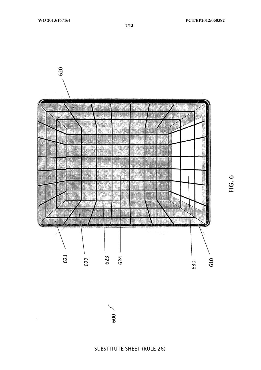
11 varying nature of the spatial presence factors may either be set manually by a sound engineer or automatically following a predetermined algorithm. In one aspect of the invention, the manual setting of presence factors enables the live adaptation of reproduced sound to a particular audience experience. [0047] One example wherein the time-varying nature of this aspect is useful is audio reproduction in concert halls. In case of concert halls, the sound engineer can, on one hand, reproduce a pre-recorded audio signal to suit the environment and particular loudspeaker layout optimally. On the other, while ongoing reproduction takes place, the sound engineer, or even musician, can partake in creating an immersive audio experience by varying the spatial presence factors of different regions of space D in a creative manner. This could enhance the concert experienced by participants listening to a live DJ, who, using feedback received directly from the audience, decides to interact with them musically by varying the shape, volume, and region of different instrument channels without any latency involved. [0048] Another example wherein the time-varying nature of this aspect is useful is technical compensation for cases wherein the reproduction environment has a fixed loudspeaker layout not particularly suited for producing the best audio effects from a particular recording. In such case, the sound engineer can compensate for areas of space D with low audio coverage, to produce a higher audio presence in these areas, and on the other hand reduce the audio presence in areas in direct proximity to the loudspeakers, hence normalizing the listening experience throughout the whole space D. [0049] FIG. 6 depicts a user interface view 600 according to one aspect of the present invention, wherein the creation and manipulation of the spatial presence factors m is done intuitively by means of a tactile interface 610. The interface shows a view of a cinema from beneath the cinema hall. In this particular configuration, the hall is represented via the rectangular space D model divided into a plurality of partitions 620. Portion 624 is a portion of partition set S located at the cinema ceiling, and portions 621, 622, and 623 are portions located at the cinema side wall. The cinema screen 630 is shown in white at one end of the hall. [0050] FIG. 7 depicts the same user interface of FIG. 6 being manipulated by a user, such as a sound engineer or musician. The user's hand 710 and therefore fingers can
12 move throughout the tactile interface thereby assigning different values to the spatial presence factors m. This is done intuitively, in the sense that the user interface facilitates easy manipulation by the end user, however the user does not have to be an experienced sound engineer. The portions 720 being assigned by the fingers, in light colour, define and locate a particular audio signal, or can define and locate different audio signals to different portions thereby resulting in a highly complex apparent sound size and shape. The shape is easily defined and manipulated, even when, as in this case, it is made of two disconnected parts. In one aspect of the invention, the algorithms implemented by the system assign high spatial presence values to the portions selected by the finger touch, in light colour, and low values to the other portions, in darker colour. [0051] In one particular aspect, the spatial presence factors are generated by assigning intermediate values to factors in intermediate zones. Intermediate zones are defined as zones between finger-selected zones with high factor values, and far removed zones with very low factor values. In this manner a desired degree of continuity in between different portions of S is ensured, guaranteeing a more pleasing listening experience in the whole space D. [0052] The different possible combination of time-varying values, applied to different portions, facilitates the reproduction of extremely complex audio images in a 3D environment to even inexpert users. Hence the system enables users to, awarely or unawarely, effortlessly edit the values for m^. This in turn facilitates the automatic conversion of any input audio format into any output audio format independent of reproduction layout or number of channels to be performed by the different embodiments of the invention. [0053] FIG. 4 depicts a system 400 for channel-independent representation according to one aspect of the invention, which is useful for upmixing standard 5.1 and 7.1 content to 3D; other input formats are also possible by straightforward extension of the following. This view depicts an original set of input 5.1 or 7.1 channels. For 5.1, the first five channels from a typical 5.1 system, often referred to as left L, right R, center C, leftsurround Ls and right-surround Rs, are considered as original independent audio signals. The same applies for 7.1, where the two extra channels are often referred to as left-back Lb and right-back Rb. An additional low frequency effects LFE, or subwoofer,
13 signal, is also often present. In this example case eight original independent audio signals are considered. [0054] Each signal is encoded into a channel- independent representation by means o f the various aspects and embodiments described. Suitable choices of the coefficients m help increasing the immersive effect. For example, for 5.1, the left-surround channels are assigned sizes and shapes following the concept illustrated in FIG. 8, where the leftsurround channel is identified by partition set 810 and the right-surround channel is assigned sizes and shapes identified by partition set 820. [0055] The capability of the present invention to generate complex shapes proves essential in this case, as it avoids situations that would degrade and produce audible artifacts. For example, the two surround channels do not overlap in space; this allows keeping both left-right hemispheres surrounding the audience as decorrelated as possible, which results in pleasant natural sound perception. It also avoids the mixing of both signals, which would otherwise lead to annoying comb- filtering artifacts. Similarly, both surround channels are prevented from reaching the screen area 830, which would also produce unwanted effects, like reduced intelligibility of dialogues. Therefore the present invention improves the quality of sound images when upmixed from a stereo system, especially in environments requiring a high number of loudspeakers. [0056] FIG. 4 also shows an optional enhancement consisting on the use of an automatic factor generator 410, or factor generation means, which generates time-varying spatial presence factors m, the generation algorithm being based on, for example, predefined trajectories or on the result of an analysis of the input audio channels. FIG. 9 depicts suitable time-varying factor generations that enhance the immersive effect. In this aspect, the properties related to the location, size and shape of some of the channels are time-varying, and based on predefined variations of the map coefficients, for example, by making the two surround channels move in loop trajectories 910. In another embodiment, the time variation is based on an analysis of the audio in the original channels. In a first step the amount of energy present in all input channels is determined. Then the channels are identified according to their property, whether they are simple left/right stereo channels or one of 5.1/7. 1 channels. Finally, the values generated for the
14 spatial presence factors can be set to be dependent on the result of the changes in energy estimated. [0057] For example, in case the channels are surround channels, a determination is made to estimate the relative proportion of total acoustic energy present in the surround channels with respect to the remaining channels. Finally the motion of the reproduced image of the two surround channels is accelerated throughout space D based on this relative energy estimation. This causes the auditory scene motion to be synchronized with the surround level such that, depending on the original 5.1/7.1 content, an enhanced realism and spectacularity results. Other features, different from energy estimation, extracted from an analysis of the input channels may be used. [0058] FIG. 5 depicts an embodiment of the present invention wherein the system o f previous embodiments is integrated with a pre-processing stage 500 typical of many audio reproduction setups. Since many recordings exist only in a 2-channel stereo format 510, an upmixer 520 may be integrated to upmix the stereo to 5.1, or 7.1, resulting into a set of initially upmixed multichannel signals. After this initial upmix, the same aforementioned audio processing stages of previous embodiments and aspects apply to encode in a channel-independent representation the initially upmixed multichannel signals. [0059] FIG. 10 depicts a method 1000 for the selection of the representation D best suited for a particular application according to one embodiment of the present invention. In step 1010 the user is prompted for information or directly for a selection from a list of possible space D shapes and topologies best suited for the particular reproduction environment in which the 3D audio is to be implemented. The user may select 1020 from a list comprising circular, rectangular, squares, or any other polygons. Depending on the selected topology, the corresponding space D shape is extracted 1030 from memory and visualized in the tactile user interface for the user's facility. [0060] In case no selection is input by the user, the method proceeds to step 1040 where a default representation is selected (for example, a sphere) as the best suited shape for an unknown application. Consequently the corresponding default shape D is extracted 1040 from memory and visualized in the tactile user interface for the user's facility. After space D extraction and visualization, in step 1050 the user is presented with
15 different preset partitions of the chosen space D, each with different adjustable portion sizes. Depending on the application, the user can select a very fine partition, with very small individual portions, or coarser partitions, with larger individual portions. The algorithm then proceeds to the remaining encoding steps. [0061] FIG. 1 1 depicts a method 1100 for implementing the channel-independent algorithm according to an embodiment of the invention. Following topology and partition selection and configuration after step 1050 of method 1000, the user is prompted 1110 via the display for input on select zones where special processing is required. The user is able to provide this input by touching the tactile user interface, for example, with the fingers, or with any other suitable touching device or means. The partitions S in which contact is detected are identified 1120 and classified as selected zones. [0062] Once the select zones are identified, the best suited spatial presence factor M- scale is selected It is from this scale that values for the factor m will be extracted. In step 1140 the value of m for that particular input audio channel is determined. This process is repeated 1145 until a full matrix M for all input audio channels is determined for all portions and partitions of space D. If the result of step 1120 is that no user input is detected, the algorithm continues by default to an intermediate value of the presence factor m to apply to all input audio channels independent of partition set or portions within space D. [0063] The process for assigning a spatial presence to each input audio channel can be time-varying, by simply allowing the user to move his fingers while touching the tactile user interface, thus generating time-varying spatial presence coefficients, and optionally recording the corresponding time history of every coefficient in a time-line stream of events, as is standard in sound post-production with audio workstations and mixing consoles. [0064] Once the matrix is full, in step 1150 the mapping between input audio signal set A and output audio signal set B is performed as described. This mapping comprises performing a smooth transition between select zones with high values for m and nonselect zones with low values for m. In one aspect this smooth transition may be performed likewise by choosing consecutive values for m from the same selected M-
16 scale, or from a different one, depending on user selection. [0065] Finally, once the mapping of all partitions sets and portions of space D has been completed, associated metadata comprising spatial presence factors describing space D and partitions S is generated. The metadata together with the output signals result in the complete set of output audio signals B ready to be further processed 1160 by audio decoders and fed to the loudspeakers present in the particular venue. The method then returns 1165 to initial step 1110 in order to update its information about user tactile input, thereby yielding a dynamic algorithm running in real-time. Method 1100 is therefore an iterative algorithm which integrates user instructions into a time-varying and adaptive encoding of input audio signals A into a channel-independent representation B which solves the problems identified in the prior art. [0066] FIG. 12 depicts three examples of spatial presence factor scales The scales have in their vertical axis the range of values which the spatial presence factor m can adopt. The maximum value for m can be set depending on user selection. It can either vary between 0 and 1, or 0 and any other value, such as 100 or The horizontal axis X is a parameter which can represent a number of factors relevant for immersive sound image enhancement. [0067] In one aspect X represents a relational parameter which increases in value as the number of neighbouring selected zones increases. Hence an isolated portion will have a lower value of m than a group of portions. Likewise, within the group of portions, the center ones are assigned the highest value for m than other portions of the periphery. [0068] In another aspect X represents the distance of the selected portion from another point Z in space D, for example, the front screen of a cinema, the side walls, a particular predefined area with particular echo effects produced by the architecture of the venue. Hence the value of m assigned is based on the distance of the selected portion from this point Z. [0069] In another aspect X represents the relative acoustic energy present in that selected portion in comparison to the full energy present in all input audio signals A of all portions. Therefore a higher value for m is assigned to high relative energies, increasing thereby the spatial presence of a particular channel temporarily exhibiting high energy sound effects.
17 [0070] In another aspect X represents a pressure parameter. In other words, as the user performs tactile contact, the differences in exerted pressure are translated to the horizontal axis of the M-scale. In this aspect, the larger user pressure exerted on the tactile interface is translated to a corresponding high value for m, such that the more pressure is sensed on the tactile interface, a higher pressure parameter is assigned to that particular partition S, or portions s of a particular partition S. Therefore a higher spatial presence is forced in that specific region, independent of the inherent characteristics of the input audio signals. All of these aspects therefore receive information from the user in an intuitive and effortless manner. [0071] As an example of different M-scale possibilities, FIG. 12 represents one linear and two non-linear functions relating the determined value of m based on the different possible parameters X described. In the first linear M-scale 1210, the values of m increases directly proportional to a corresponding increase in value of parameter X. [0072] In the second non-linear M-scale 1220, the value of m increases as a logarithmic function with respect to a corresponding increase in the value of parameter X. Here, a high value of m is assigned once a relatively high predetermined threshold is exceeded. In this aspect, the spatial presence of the particular audio input will be enhanced only once the particular parameter is proximal to its maximum values as defined by the predetermined threshold. [0073] In case X represents a relational parameter, a corresponding high value of m is assigned to selected portions only when a threshold representing a high number of grouped selections is exceeded. In such case the threshold is user predefined, or set to a default of 4, representing 4 fingers. Therefore if more than 4 fingers are used, it is understood that a special significance is intended in the selected zone, translating into a higher spatial presence. In case X represents distance, a corresponding high value of m is assigned to selected portions far away from the predetermined point Z. This could be useful, for example, when a particular low immersive zone is defined for people with different needs, such as children, or spectators with auditory sensibilities. In case X represents relative acoustic energy, once a predetermined threshold is exceeded, a corresponding high value for m is assigned to correctly reflect the spectacular sound effect the high energy input signal is representing. Finally, in case X represents tactile
18 pressure, only once the pressure exceeds a certain threshold are high m values assigned. This is useful in situations where tactile behavior changes from user to user who press with different strength. It therefore adapts to the user in question. [0074] In the third non-linear M-scale 1230, the value of m increases as a logarithmic function with respect to a corresponding increase in the value of parameter X, however the relation changes with respect to the previous non-linear scale Here, a high value of m is assigned once a relatively low predetermined threshold is exceeded. In this aspect, the spatial presence of the particular audio input will be enhanced immediately once the particular parameter is proximal to a relatively low value as defined by the predetermined threshold. [0075] In case X represents a relational parameter, a corresponding high value of m is assigned to selected portions as soon as a threshold representing a low number of grouped selections is exceeded. In such case the threshold is user predefined, or set to a default of 2, representing 2 fingers. Therefore if more than 2 fingers are used, it is understood that a special significance is intended in the selected zone, translating into a higher spatial presence. This aspect also enables more than a single portion to be selected via a swipe finger action. In case X represents distance, a corresponding high value of m is assigned to selected portions close to a predetermined point Z. This could be useful, for example, to amplify the immersive experience is zones far away from the optimum loudspeaker hotspot. In case X represents relative acoustic energy, once a predetermined threshold is exceeded, a corresponding high value for m is assigned to correctly reflect the spectacular sound effect the high energy input signal is representing. However, in this case, the method would be highly reactive to any small variations in input energy due to the low threshold of the logarithmic scale. Finally, in case X represents tactile pressure, once the pressure exceeds a low threshold are high m values assigned. This is useful in situations where the user requires performing delicate actions with low pressure touches. It therefore adapts to the user in question. [0076] It is to be understood by the skilled person in the art that the disclosure of the various embodiments of the invention is intended as non-limitative preferred examples and realizations of the inventions, and therefore features of different embodiments may be readily combined within the scope of the general inventive concept described.
19 [0077] It is to be understood that the embodiments described herein may be implemented by hardware, software, firmware, middleware, microcode, or any combination thereof. When the systems and/or methods are implemented in software, firmware, middleware or microcode, program code or code segments, a computer program, they may be stored in a machine-readable medium, such as a storage component. A computer program or a code segment may represent a procedure, a function, a subprogram, a program, a routine, a subroutine, a module, a software package, a class, or any combination of instructions, data structures, or program statements. A code segment may be coupled to another code segment or a hardware circuit by passing and/or receiving information, data, arguments, parameters, or memory contents. Information, arguments, parameters, data, etc. may be passed, forwarded, or transmitted using any suitable means including memory sharing, message passing, token passing, network transmission, and so forth. [0078] For a software implementation, the techniques described herein may be implemented with modules (e.g., procedures, functions, and so on) that perform the functions described herein. The software codes may be stored in memory units and executed by processors. The memory unit may be implemented within the processor or external to the processor, in which case it can be communicatively coupled to the processor through various means as is known in the art. Further, at least one processor may include one or more modules operable to perform the functions described herein. [0079] For a hardware implementation, the various logical blocks, modules, and circuits described in connection with the embodiments disclosed herein may be implemented of performed with a general purpose processor, a digital signal processor (DSP), and application specific integrated circuit (ASIC), a field programmable gate array (FPGA), or other programmable logic device, discrete gate or transistor logic, discrete hardware components, or any combination thereof designed to perform the functions described. A general-purpose processor may be a microprocessor, but in the alternative, the processor may be any conventional processor, controller, microcontroller, or state machine. [0080] The methods or algorithms described may be embodied directly in hardware, in a software module executed by a processor, or a combination of the two. A software module may reside in RAM memory, flash memory, ROM memory, EPROM memory,
20 EEPROM memory, registers, hard disk, a removable disk, a CD-ROM, or any other form of storage medium known in the art. [0081] Those skilled in the art should appreciate that the foregoing discussion of one or more embodiments does not limit the present invention, nor do the accompanying figures. Rather, the present invention is limited only by the following claims.
21 A device for encoding at least one input audio signal into a channel-independent representation comprising at least one output audio signal for reproduction over arbitrary loudspeaker layouts, wherein the input audio signals comprise individual tracks or streams of a multichannel content, the device comprising: means for defining a space D covering a target audience; means for dividing the space D into a plurality of portions k; means for generating at least one spatial presence factor m for each combination of input audio and portion k, wherein each factor m quantifies a degree of presence of each input audio signal into each portion k of space D; and means for mapping the at least one input audio signal to the at least one output audio signal, for reproduction within the portion k, based on the value assigned to each spatial presence factor m. The device of claim 1, wherein the output channel-independent representation further comprises information describing the space D surrounding the intended audience and a partition of space D into the plurality of portions. The device of claim 2, wherein the space D is defined by selecting a space D with an arbitrary shape, a spherical shape, a rectangular shape, or any other surface. The device of claim 2, wherein the space D is divided into finer portions, or coarser portions, or a combination of finer and coarser portions, and wherein the portions can be of regular or irregular shapes. The device of claim 2, wherein each factor m is generated by assigning a value manually or automatically, and wherein the value assigned to each factor m is fixed or time-varying, the time variance being determined manually, or
22 following preset instructions, or being generated automatically depending on the content of the input audio signals. 6. The device of claim 2, wherein a particular portion of the space D is selected by detecting contact in a tactile user interface wherein the space D, or a part of it, has been displayed. 7. The device of claim 6, wherein the spatial presence factor m corresponding to each selected portion is assigned a high value, and the remaining portions are assigned gradually diminishing lower values. 8. The device of claim 7, wherein the value assigned to each factor m of a remaining portion increases proportionally to the number of neighbouring selected portions. 9. The device of claim 7, wherein the value assigned to each factor m of a remaining portion decreases proportionally to the distance from a selected portion. 10. The device of claim 7, wherein the value assigned to each factor m of a remaining portion increases proportionally to the relative acoustic energy present in a selected portion, wherein the relative energy is the acoustic energy in comparison to the total amount of acoustic energy in all input audio signals of all portions. 11. The device of claim 7, wherein the value assigned to each factor m of a selected or remaining portion increases proportionally to the tactile pressure sensed on the selected portion of the tactile user interface. 12. The device of claim 7, wherein the input audio signals comprise only two individual tracks, or streams of a stereo track, the device further comprising pre-
23 processing means for upmixing the two input audio signals to 4.0, 5.1 or 7.1 audio signals prior to the generation of the channel-independent representation. A method of encoding at least one input audio signal into a channel-independent representation comprising at least one output audio signal suitable for reproduction over arbitrary loudspeaker layouts, wherein the input audio signals comprise individual tracks or streams of a multichannel content, the method comprising: defining a space D covering a target audience; dividing the space D into a plurality of portions k; generating at least one spatial presence factor m for each combination of input audio and portion k, wherein each factor m quantifies a degree of presence of each input audio signal into each portion k of space D; and mapping the at least one input audio signal to the at least one output audio signal, for reproduction within the portion k, based on the value assigned to each spatial presence factor m. The method of claim 13, wherein the output channel-independent representation further comprises information describing the space D surrounding the intended audience and a partition of space D into the plurality of portions. The method of claim 13, wherein the input audio signals comprise only two individual tracks, or streams of a stereo track, the method further comprising upmixing the two input audio signals to 4.0, 5.1 or 7.1 audio signals prior to the generation of the channel-independent representation. A device for decoding a channel-independent representation comprising at least one output audio signal for reproduction over arbitrary loudspeaker layouts, the device comprising: means for receiving the at least one channel-independent representation;
24 means for extracting the at least one output audio signal from the at least one channel-independent representation; means for reproducing the at least one output audio signal over the arbitrary loudspeaker layout, wherein the at least one output audio signal is reproduced over a plurality of portions k of a space D covering a target audience. 17. The device of claim 16, wherein the output channel-independent representation further comprises information describing the space D surrounding the intended audience and a partition of space D into the plurality of portions. 18. A method of decoding a channel-independent representation comprising at least one output audio signal for reproduction over arbitrary loudspeaker layouts, the method comprising: receiving the at least one channel-independent representation; extracting the at least one output audio signal from the at least one channelindependent representation; reproducing the at least one output audio signal over the arbitrary loudspeaker layout, wherein the at least one output audio signal is reproduced over a plurality of portions k of a space D covering a target audience. 19. The method of claim 18, wherein the output channel-independent representation further comprises information describing the space D surrounding the intended audience and a partition of space D into a plurality of portions. 20. A system for generating, from at least one input audio signal, at least one channel-independent representation comprising at least one output audio signal suitable for reproduction over arbitrary loudspeaker layouts, wherein the input audio signals comprise individual tracks or streams of a multichannel content, the system comprising:
25 means for collecting at least one input audio signal; means for encoding the at least one input audio signal into a channelindependent representation according to any one of claims 1 to 12; means for decoding the at least one channel-independent representation into at least one output audio signal and for reproducing the at least one output audio signal via the arbitrary loudspeaker layout according to any one of claims 16 to 17. The system of claim 20, wherein the input audio signals comprise only two individual tracks, or streams of a stereo track, the system further comprising a pre-processing stage for upmixing the two input audio signals to 4.0, 5.1 or 7.1 audio signals prior to the generation of the channel-independent representation. A method of generating, from at least one input audio signal, at least one channel-independent representation comprising at least one output audio signal suitable for reproduction over arbitrary loudspeaker layouts, wherein the input audio signals comprise individual tracks or streams of a multichannel content, the method comprising: collecting at least one input audio signal; encoding the at least one input audio signal into a channel-independent representation according to any one of claims 13 to 15; decoding the at least one channel-independent representation into at least one output audio signal and for reproducing the at least one output audio signal via the arbitrary loudspeaker layout according to any one of claims 18 to 19. The method of claim 22, wherein the input audio signals comprise only two individual tracks, or streams of a stereo track, the method further comprising upmixing the two input audio signals to 4.0, 5.1 or 7.1 audio signals prior to the generation of the channel-independent representation.
26 24. A computer program, which when executed on a computing machine, reproduces the steps of any one of method claims 13 to 15, 18 to 19, or 22 to A computer readable medium comprising instructions which, when executed on a machine, perform the steps of any one of method claims 13 to 15, 18 to 19, or 22 to 23.
27
28
29
30
31
32
33
TEPZZ A_T EP A1 (19) (11) EP A1 (12) EUROPEAN PATENT APPLICATION. (51) Int Cl.: H04S 7/00 ( ) H04R 25/00 (2006.
 (11) EP A1 (12) EUROPEAN PATENT APPLICATION. (51) Int Cl.: H04S 7/00 ( ) H04R 25/00 (2006.") (19) TEPZZ 94 98 A_T (11) EP 2 942 982 A1 (12) EUROPEAN PATENT APPLICATION (43) Date of publication: 11.11. Bulletin /46 (1) Int Cl.: H04S 7/00 (06.01) H04R /00 (06.01) (21) Application number: 141838.7
(19) TEPZZ 94 98 A_T (11) EP 2 942 982 A1 (12) EUROPEAN PATENT APPLICATION (43) Date of publication: 11.11. Bulletin /46 (1) Int Cl.: H04S 7/00 (06.01) H04R /00 (06.01) (21) Application number: 141838.7
TEPZZ 94 98_A_T EP A1 (19) (11) EP A1 (12) EUROPEAN PATENT APPLICATION. (43) Date of publication: Bulletin 2015/46
 (11) EP A1 (12) EUROPEAN PATENT APPLICATION. (43) Date of publication: Bulletin 2015/46") (19) TEPZZ 94 98_A_T (11) EP 2 942 981 A1 (12) EUROPEAN PATENT APPLICATION (43) Date of publication: 11.11.1 Bulletin 1/46 (1) Int Cl.: H04S 7/00 (06.01) H04R /00 (06.01) (21) Application number: 1418384.0
(19) TEPZZ 94 98_A_T (11) EP 2 942 981 A1 (12) EUROPEAN PATENT APPLICATION (43) Date of publication: 11.11.1 Bulletin 1/46 (1) Int Cl.: H04S 7/00 (06.01) H04R /00 (06.01) (21) Application number: 1418384.0
(12) INTERNATIONAL APPLICATION PUBLISHED UNDER THE PATENT COOPERATION TREATY (PCT)
 INTERNATIONAL APPLICATION PUBLISHED UNDER THE PATENT COOPERATION TREATY (PCT)") (12) INTERNATIONAL APPLICATION PUBLISHED UNDER THE PATENT COOPERATION TREATY (PCT) (19) World Intellectual Property Organization International Bureau (10) International Publication Number (43) International
(12) INTERNATIONAL APPLICATION PUBLISHED UNDER THE PATENT COOPERATION TREATY (PCT) (19) World Intellectual Property Organization International Bureau (10) International Publication Number (43) International
TEPZZ A_T EP A1 (19) (11) EP A1 (12) EUROPEAN PATENT APPLICATION. (43) Date of publication: Bulletin 2015/10
 (11) EP A1 (12) EUROPEAN PATENT APPLICATION. (43) Date of publication: Bulletin 2015/10") (19) TEPZZ 84 9 6A_T (11) EP 2 843 926 A1 (12) EUROPEAN PATENT APPLICATION (43) Date of publication: 04.03.1 Bulletin 1/ (1) Int Cl.: H04M 19/08 (06.01) H04L 12/ (06.01) (21) Application number: 136194.
(19) TEPZZ 84 9 6A_T (11) EP 2 843 926 A1 (12) EUROPEAN PATENT APPLICATION (43) Date of publication: 04.03.1 Bulletin 1/ (1) Int Cl.: H04M 19/08 (06.01) H04L 12/ (06.01) (21) Application number: 136194.
#9 Lane 32, Wu-Fu 1 Rd., Lu-Chu, Taoyuan City (TW).
.") (12) INTERNATIONAL APPLICATION PUBLISHED UNDER THE PATENT COOPERATION TREATY (PCT) (19) World Intellectual Property Organization International Bureau (43) International Publication Date (10) International
(12) INTERNATIONAL APPLICATION PUBLISHED UNDER THE PATENT COOPERATION TREATY (PCT) (19) World Intellectual Property Organization International Bureau (43) International Publication Date (10) International
EP A2 (19) (11) EP A2 (12) EUROPEAN PATENT APPLICATION. (43) Date of publication: Bulletin 2012/20
 (11) EP A2 (12) EUROPEAN PATENT APPLICATION. (43) Date of publication: Bulletin 2012/20") (19) (12) EUROPEAN PATENT APPLICATION (11) EP 2 43 301 A2 (43) Date of publication: 16.0.2012 Bulletin 2012/20 (1) Int Cl.: G02F 1/1337 (2006.01) (21) Application number: 11103.3 (22) Date of filing: 22.02.2011
(19) (12) EUROPEAN PATENT APPLICATION (11) EP 2 43 301 A2 (43) Date of publication: 16.0.2012 Bulletin 2012/20 (1) Int Cl.: G02F 1/1337 (2006.01) (21) Application number: 11103.3 (22) Date of filing: 22.02.2011
TEPZZ 996Z 5A_T EP A1 (19) (11) EP A1 (12) EUROPEAN PATENT APPLICATION. (51) Int Cl.: G06F 3/06 ( )
 (11) EP A1 (12) EUROPEAN PATENT APPLICATION. (51) Int Cl.: G06F 3/06 ( )") (19) TEPZZ 996Z A_T (11) EP 2 996 02 A1 (12) EUROPEAN PATENT APPLICATION (43) Date of publication: 16.03.16 Bulletin 16/11 (1) Int Cl.: G06F 3/06 (06.01) (21) Application number: 14184344.1 (22) Date of
(19) TEPZZ 996Z A_T (11) EP 2 996 02 A1 (12) EUROPEAN PATENT APPLICATION (43) Date of publication: 16.03.16 Bulletin 16/11 (1) Int Cl.: G06F 3/06 (06.01) (21) Application number: 14184344.1 (22) Date of
EP A2 (19) (11) EP A2 (12) EUROPEAN PATENT APPLICATION. (43) Date of publication: Bulletin 2011/39
 (11) EP A2 (12) EUROPEAN PATENT APPLICATION. (43) Date of publication: Bulletin 2011/39") (19) (12) EUROPEAN PATENT APPLICATION (11) EP 2 368 716 A2 (43) Date of publication: 28.09.2011 Bulletin 2011/39 (51) Int Cl.: B41J 3/407 (2006.01) G06F 17/21 (2006.01) (21) Application number: 11157523.9
(19) (12) EUROPEAN PATENT APPLICATION (11) EP 2 368 716 A2 (43) Date of publication: 28.09.2011 Bulletin 2011/39 (51) Int Cl.: B41J 3/407 (2006.01) G06F 17/21 (2006.01) (21) Application number: 11157523.9
TEPZZ A_T EP A1 (19) (11) EP A1. (12) EUROPEAN PATENT APPLICATION published in accordance with Art.
 (11) EP A1. (12) EUROPEAN PATENT APPLICATION published in accordance with Art.") (19) TEPZZ 8946 9A_T (11) EP 2 894 629 A1 (12) EUROPEAN PATENT APPLICATION published in accordance with Art. 13(4) EPC (43) Date of publication: 1.07.1 Bulletin 1/29 (21) Application number: 12889136.3
(19) TEPZZ 8946 9A_T (11) EP 2 894 629 A1 (12) EUROPEAN PATENT APPLICATION published in accordance with Art. 13(4) EPC (43) Date of publication: 1.07.1 Bulletin 1/29 (21) Application number: 12889136.3
PCT WO 2007/ Al
 (12) INTERNATIONAL APPLICATION PUBLISHED UNDER THE PATENT COOPERATION TREATY (PCT) (19) World Intellectual Property Organization International Bureau (43) International Publication Date (10) International
TEPZZ 55_Z ZA_T EP A1 (19) (11) EP A1 (12) EUROPEAN PATENT APPLICATION
 (11) EP A1 (12) EUROPEAN PATENT APPLICATION") (19) TEPZZ 55_Z ZA_T (11) EP 2 551 030 A1 (12) EUROPEAN PATENT APPLICATION (43) Date of publication: 30.01.2013 Bulletin 2013/05 (21) Application number: 12176888.1 (51) Int Cl.: B21D 28/22 (2006.01) H02K
(19) TEPZZ 55_Z ZA_T (11) EP 2 551 030 A1 (12) EUROPEAN PATENT APPLICATION (43) Date of publication: 30.01.2013 Bulletin 2013/05 (21) Application number: 12176888.1 (51) Int Cl.: B21D 28/22 (2006.01) H02K
METHOD, COMPUTER PROGRAM AND APPARATUS FOR DETERMINING MOTION INFORMATION FIELD OF THE INVENTION
 1 METHOD, COMPUTER PROGRAM AND APPARATUS FOR DETERMINING MOTION INFORMATION FIELD OF THE INVENTION The present invention relates to motion 5tracking. More particularly, the present invention relates to
PCT LR, LS, LT, LU, LY, MA, MD, ME, MG, MK, MN, MW,
 (12) INTERNATIONAL APPLICATION PUBLISHED UNDER THE PATENT COOPERATION TREATY (PCT) (19) World Intellectual Property Organization International Bureau (43) International Publication Date (10) International
TEPZZ 889A_T EP A1 (19) (11) EP A1 (12) EUROPEAN PATENT APPLICATION. (43) Date of publication: Bulletin 2017/35
 (11) EP A1 (12) EUROPEAN PATENT APPLICATION. (43) Date of publication: Bulletin 2017/35") (19) TEPZZ 889A_T (11) EP 3 211 889 A1 (12) EUROPEAN PATENT APPLICATION (43) Date of publication:.08.17 Bulletin 17/3 (21) Application number: 163970. (22) Date of filing: 26.02.16 (1) Int Cl.: H04N 7/
(19) TEPZZ 889A_T (11) EP 3 211 889 A1 (12) EUROPEAN PATENT APPLICATION (43) Date of publication:.08.17 Bulletin 17/3 (21) Application number: 163970. (22) Date of filing: 26.02.16 (1) Int Cl.: H04N 7/
(51) Int Cl.: H04L 1/00 ( )
 Int Cl.: H04L 1/00 ( )") (19) TEPZZ Z4 497A_T (11) EP 3 043 497 A1 (12) EUROPEAN PATENT APPLICATION published in accordance with Art. 153(4) EPC (43) Date of publication: 13.07.2016 Bulletin 2016/28 (21) Application number: 14842584.6
(19) TEPZZ Z4 497A_T (11) EP 3 043 497 A1 (12) EUROPEAN PATENT APPLICATION published in accordance with Art. 153(4) EPC (43) Date of publication: 13.07.2016 Bulletin 2016/28 (21) Application number: 14842584.6
DISTRIBUTION STATEMENT A 7001Ö
 Serial Number 09/678.881 Filing Date 4 October 2000 Inventor Robert C. Higgins NOTICE The above identified patent application is available for licensing. Requests for information should be addressed to:
(51) Int Cl.: G10L 19/00 ( ) G10L 19/02 ( ) G10L 21/04 ( )
 Int Cl.: G10L 19/00 ( ) G10L 19/02 ( ) G10L 21/04 ( )") (19) TEPZZ 6Z485B_T (11) EP 2 260 485 B1 (12) EUROPEAN PATENT SPECIFICATION (45) Date of publication and mention of the grant of the patent: 03.04.2013 Bulletin 2013/14 (21) Application number: 09776910.3
(19) TEPZZ 6Z485B_T (11) EP 2 260 485 B1 (12) EUROPEAN PATENT SPECIFICATION (45) Date of publication and mention of the grant of the patent: 03.04.2013 Bulletin 2013/14 (21) Application number: 09776910.3
(12) Patent Application Publication (10) Pub. No.: US 2005/ A1
 Patent Application Publication (10) Pub. No.: US 2005/ A1") (19) United States US 20050008347A1 (12) Patent Application Publication (10) Pub. No.: US 2005/0008347 A1 Jung et al. (43) Pub. Date: Jan. 13, 2005 (54) METHOD OF PROCESSING SUBTITLE STREAM, REPRODUCING
(19) United States US 20050008347A1 (12) Patent Application Publication (10) Pub. No.: US 2005/0008347 A1 Jung et al. (43) Pub. Date: Jan. 13, 2005 (54) METHOD OF PROCESSING SUBTITLE STREAM, REPRODUCING
International film co-production in Europe
 International film co-production in Europe A publication May 2018 Index 1. What is a co-production? 2. Legal instruments for co-production 3. Production in Europe 4. Co-production volume in Europe 5. Co-production
(12) Publication of Unexamined Patent Application (A)
 Publication of Unexamined Patent Application (A)") Case #: JP H9-102827A (19) JAPANESE PATENT OFFICE (51) Int. Cl. 6 H04 M 11/00 G11B 15/02 H04Q 9/00 9/02 (12) Publication of Unexamined Patent Application (A) Identification Symbol 301 346 301 311 JPO File
Case #: JP H9-102827A (19) JAPANESE PATENT OFFICE (51) Int. Cl. 6 H04 M 11/00 G11B 15/02 H04Q 9/00 9/02 (12) Publication of Unexamined Patent Application (A) Identification Symbol 301 346 301 311 JPO File
FREE TV AUSTRALIA OPERATIONAL PRACTICE OP- 59 Measurement and Management of Loudness in Soundtracks for Television Broadcasting
 Page 1 of 10 1. SCOPE This Operational Practice is recommended by Free TV Australia and refers to the measurement of audio loudness as distinct from audio level. It sets out guidelines for measuring and
SELECTING A HIGH-VALENCE REPRESENTATIVE IMAGE BASED ON IMAGE QUALITY. Inventors: Nicholas P. Dufour, Mark Desnoyer, Sophie Lebrecht
 Page 1 of 74 SELECTING A HIGH-VALENCE REPRESENTATIVE IMAGE BASED ON IMAGE QUALITY Inventors: Nicholas P. Dufour, Mark Desnoyer, Sophie Lebrecht TECHNICAL FIELD methods. [0001] This disclosure generally
TEPZZ 7 9_Z B_T EP B1 (19) (11) EP B1 (12) EUROPEAN PATENT SPECIFICATION
 (11) EP B1 (12) EUROPEAN PATENT SPECIFICATION") (19) TEPZZ 7 9_Z B_T (11) EP 2 739 2 B1 (12) EUROPEAN PATENT SPECIFICATION (4) Date of publication and mention of the grant of the patent: 27.07.16 Bulletin 16/ (21) Application number: 12823933.2 (22)
(19) TEPZZ 7 9_Z B_T (11) EP 2 739 2 B1 (12) EUROPEAN PATENT SPECIFICATION (4) Date of publication and mention of the grant of the patent: 27.07.16 Bulletin 16/ (21) Application number: 12823933.2 (22)
Designated contracting state (EPC) AT BE BG CH CY CZ DE DK EE ES FI FR GB GR HU IE IS IT LI LT LU LV MC NL PL PT RO SE SI SK TR
 AT BE BG CH CY CZ DE DK EE ES FI FR GB GR HU IE IS IT LI LT LU LV MC NL PL PT RO SE SI SK TR") Title (en) METHOD FOR EVACUATING BUILDINGS DIVIDED INTO SECTIONS Title (de) VERFAHREN ZUR EVAKUIERUNG VON IN SEKTIONEN EINGETEILTEN GEBÄUDEN Title (fr) PROCEDE POUR EVACUER DES BATIMENTS DIVISES EN SECTIONS
Title (en) METHOD FOR EVACUATING BUILDINGS DIVIDED INTO SECTIONS Title (de) VERFAHREN ZUR EVAKUIERUNG VON IN SEKTIONEN EINGETEILTEN GEBÄUDEN Title (fr) PROCEDE POUR EVACUER DES BATIMENTS DIVISES EN SECTIONS
2) }25 2 O TUNE IF. CHANNEL, TS i AUDIO
 }25 2 O TUNE IF. CHANNEL, TS i AUDIO") US 20050160453A1 (19) United States (12) Patent Application Publication (10) Pub. N0.: US 2005/0160453 A1 Kim (43) Pub. Date: (54) APPARATUS TO CHANGE A CHANNEL (52) US. Cl...... 725/39; 725/38; 725/120;
US 20050160453A1 (19) United States (12) Patent Application Publication (10) Pub. N0.: US 2005/0160453 A1 Kim (43) Pub. Date: (54) APPARATUS TO CHANGE A CHANNEL (52) US. Cl...... 725/39; 725/38; 725/120;
(12) Patent Application Publication (10) Pub. No.: US 2006/ A1. (51) Int. Cl. SELECT A PLURALITY OF TIME SHIFT CHANNELS
 Patent Application Publication (10) Pub. No.: US 2006/ A1. (51) Int. Cl. SELECT A PLURALITY OF TIME SHIFT CHANNELS") (19) United States (12) Patent Application Publication (10) Pub. No.: Lee US 2006OO15914A1 (43) Pub. Date: Jan. 19, 2006 (54) RECORDING METHOD AND APPARATUS CAPABLE OF TIME SHIFTING INA PLURALITY OF CHANNELS
(19) United States (12) Patent Application Publication (10) Pub. No.: Lee US 2006OO15914A1 (43) Pub. Date: Jan. 19, 2006 (54) RECORDING METHOD AND APPARATUS CAPABLE OF TIME SHIFTING INA PLURALITY OF CHANNELS
SUMMIT LAW GROUP PLLC 315 FIFTH AVENUE SOUTH, SUITE 1000 SEATTLE, WASHINGTON Telephone: (206) Fax: (206)
 Fax: (206)") Case 2:10-cv-01823-JLR Document 154 Filed 01/06/12 Page 1 of 153 1 The Honorable James L. Robart 2 3 4 5 6 7 UNITED STATES DISTRICT COURT FOR THE WESTERN DISTRICT OF WASHINGTON AT SEATTLE 8 9 10 11 12
Case 2:10-cv-01823-JLR Document 154 Filed 01/06/12 Page 1 of 153 1 The Honorable James L. Robart 2 3 4 5 6 7 UNITED STATES DISTRICT COURT FOR THE WESTERN DISTRICT OF WASHINGTON AT SEATTLE 8 9 10 11 12
TEPZZ 797Z A T EP A2 (19) (11) EP A2 (12) EUROPEAN PATENT APPLICATION. (51) Int Cl.: G06K 9/00 ( ) G06K 9/22 (2006.
 (11) EP A2 (12) EUROPEAN PATENT APPLICATION. (51) Int Cl.: G06K 9/00 ( ) G06K 9/22 (2006.") (19) TEPZZ 797Z A T (11) EP 2 797 032 A2 (12) EUROPEAN PATENT APPLICATION (43) Date of publication: 29..14 Bulletin 14/44 (1) Int Cl.: G06K 9/00 (06.01) G06K 9/22 (06.01) (21) Application number: 1416179.4
(19) TEPZZ 797Z A T (11) EP 2 797 032 A2 (12) EUROPEAN PATENT APPLICATION (43) Date of publication: 29..14 Bulletin 14/44 (1) Int Cl.: G06K 9/00 (06.01) G06K 9/22 (06.01) (21) Application number: 1416179.4
(12) United States Patent
 United States Patent") (12) United States Patent Ali USOO65O1400B2 (10) Patent No.: (45) Date of Patent: Dec. 31, 2002 (54) CORRECTION OF OPERATIONAL AMPLIFIER GAIN ERROR IN PIPELINED ANALOG TO DIGITAL CONVERTERS (75) Inventor:
(12) United States Patent Ali USOO65O1400B2 (10) Patent No.: (45) Date of Patent: Dec. 31, 2002 (54) CORRECTION OF OPERATIONAL AMPLIFIER GAIN ERROR IN PIPELINED ANALOG TO DIGITAL CONVERTERS (75) Inventor:
(12) Patent Application Publication (10) Pub. No.: US 2007/ A1
 Patent Application Publication (10) Pub. No.: US 2007/ A1") (19) United States (12) Patent Application Publication (10) Pub. No.: US 2007/0230902 A1 Shen et al. US 20070230902A1 (43) Pub. Date: Oct. 4, 2007 (54) (75) (73) (21) (22) (60) DYNAMIC DISASTER RECOVERY
(19) United States (12) Patent Application Publication (10) Pub. No.: US 2007/0230902 A1 Shen et al. US 20070230902A1 (43) Pub. Date: Oct. 4, 2007 (54) (75) (73) (21) (22) (60) DYNAMIC DISASTER RECOVERY
ATSC Standard: A/342 Part 1, Audio Common Elements
 ATSC Standard: A/342 Part 1, Common Elements Doc. A/342-1:2017 24 January 2017 Advanced Television Systems Committee 1776 K Street, N.W. Washington, DC 20006 202-872-9160 i The Advanced Television Systems
Optimization of Multi-Channel BCH Error Decoding for Common Cases. Russell Dill Master's Thesis Defense April 20, 2015
 Optimization of Multi-Channel BCH Error Decoding for Common Cases Russell Dill Master's Thesis Defense April 20, 2015 Bose-Chaudhuri-Hocquenghem (BCH) BCH is an Error Correcting Code (ECC) and is used
BeoVision Televisions
 BeoVision Televisions Technical Sound Guide Bang & Olufsen A/S January 4, 2017 Please note that not all BeoVision models are equipped with all features and functions mentioned in this guide. Contents 1
THE MPEG-H TV AUDIO SYSTEM
 This whitepaper was produced in collaboration with Fraunhofer IIS. THE MPEG-H TV AUDIO SYSTEM Use Cases and Workflows MEDIA SOLUTIONS FRAUNHOFER ISS THE MPEG-H TV AUDIO SYSTEM INTRODUCTION This document
UNIVERSITY OF CAMBRIDGE INTERNATIONAL EXAMINATIONS General Certificate of Education Ordinary Level. Paper 1 October/November hours 30 minutes
 *35654* UNIVERSITY OF CAMBRIDGE INTERNATIONAL EXAMINATIONS General Certificate of Education Ordinary Level COMPUTER STUDIES 7/3 Paper October/November 3 hours 3 minutes Candidates answer on the Question
2. AN INTROSPECTION OF THE MORPHING PROCESS
 1. INTRODUCTION Voice morphing means the transition of one speech signal into another. Like image morphing, speech morphing aims to preserve the shared characteristics of the starting and final signals,
(12) Patent Application Publication (10) Pub. No.: US 2004/ A1. Kusumoto (43) Pub. Date: Oct. 7, 2004
 Patent Application Publication (10) Pub. No.: US 2004/ A1. Kusumoto (43) Pub. Date: Oct. 7, 2004") US 2004O1946.13A1 (19) United States (12) Patent Application Publication (10) Pub. No.: US 2004/0194613 A1 Kusumoto (43) Pub. Date: Oct. 7, 2004 (54) EFFECT SYSTEM (30) Foreign Application Priority Data
US 2004O1946.13A1 (19) United States (12) Patent Application Publication (10) Pub. No.: US 2004/0194613 A1 Kusumoto (43) Pub. Date: Oct. 7, 2004 (54) EFFECT SYSTEM (30) Foreign Application Priority Data
(12) Patent Application Publication (10) Pub. No.: US 2004/ A1
 Patent Application Publication (10) Pub. No.: US 2004/ A1") (19) United States US 2004O184531A1 (12) Patent Application Publication (10) Pub. No.: US 2004/0184531A1 Lim et al. (43) Pub. Date: Sep. 23, 2004 (54) DUAL VIDEO COMPRESSION METHOD Publication Classification
(19) United States US 2004O184531A1 (12) Patent Application Publication (10) Pub. No.: US 2004/0184531A1 Lim et al. (43) Pub. Date: Sep. 23, 2004 (54) DUAL VIDEO COMPRESSION METHOD Publication Classification
Motion Video Compression
 7 Motion Video Compression 7.1 Motion video Motion video contains massive amounts of redundant information. This is because each image has redundant information and also because there are very few changes
ACTIVE SOUND DESIGN: VACUUM CLEANER
 ACTIVE SOUND DESIGN: VACUUM CLEANER PACS REFERENCE: 43.50 Qp Bodden, Markus (1); Iglseder, Heinrich (2) (1): Ingenieurbüro Dr. Bodden; (2): STMS Ingenieurbüro (1): Ursulastr. 21; (2): im Fasanenkamp 10
(12) Patent Application Publication (10) Pub. No.: US 2006/ A1. (51) Int. Cl.
 Patent Application Publication (10) Pub. No.: US 2006/ A1. (51) Int. Cl.") (19) United States US 20060034.186A1 (12) Patent Application Publication (10) Pub. No.: US 2006/0034186 A1 Kim et al. (43) Pub. Date: Feb. 16, 2006 (54) FRAME TRANSMISSION METHOD IN WIRELESS ENVIRONMENT
(19) United States US 20060034.186A1 (12) Patent Application Publication (10) Pub. No.: US 2006/0034186 A1 Kim et al. (43) Pub. Date: Feb. 16, 2006 (54) FRAME TRANSMISSION METHOD IN WIRELESS ENVIRONMENT
Sound Measurement. V2: 10 Nov 2011 WHITE PAPER. IMAGE PROCESSING TECHNIQUES
 www.omnitek.tv IMAGE PROCESSING TECHNIQUES Sound Measurement An important element in the assessment of video for broadcast is the assessment of its audio content. This audio can be delivered in a range
Contents. Welcome to LCAST. System Requirements. Compatibility. Installation and Authorization. Loudness Metering. True-Peak Metering
 LCAST User Manual Contents Welcome to LCAST System Requirements Compatibility Installation and Authorization Loudness Metering True-Peak Metering LCAST User Interface Your First Loudness Measurement Presets
How to Obtain a Good Stereo Sound Stage in Cars
 Page 1 How to Obtain a Good Stereo Sound Stage in Cars Author: Lars-Johan Brännmark, Chief Scientist, Dirac Research First Published: November 2017 Latest Update: November 2017 Designing a sound system
AUDIOVISUAL COMMUNICATION
 AUDIOVISUAL COMMUNICATION Laboratory Session: Recommendation ITU-T H.261 Fernando Pereira The objective of this lab session about Recommendation ITU-T H.261 is to get the students familiar with many aspects
L11/12: Reconfigurable Logic Architectures
 L11/12: Reconfigurable Logic Architectures Acknowledgements: Materials in this lecture are courtesy of the following people and used with permission. - Randy H. Katz (University of California, Berkeley,
(12) United States Patent
 United States Patent") USOO9709605B2 (12) United States Patent Alley et al. (10) Patent No.: (45) Date of Patent: Jul.18, 2017 (54) SCROLLING MEASUREMENT DISPLAY TICKER FOR TEST AND MEASUREMENT INSTRUMENTS (71) Applicant: Tektronix,
USOO9709605B2 (12) United States Patent Alley et al. (10) Patent No.: (45) Date of Patent: Jul.18, 2017 (54) SCROLLING MEASUREMENT DISPLAY TICKER FOR TEST AND MEASUREMENT INSTRUMENTS (71) Applicant: Tektronix,
Figure 1: Feature Vector Sequence Generator block diagram.
 1 Introduction Figure 1: Feature Vector Sequence Generator block diagram. We propose designing a simple isolated word speech recognition system in Verilog. Our design is naturally divided into two modules.
Module 8 VIDEO CODING STANDARDS. Version 2 ECE IIT, Kharagpur
 Module 8 VIDEO CODING STANDARDS Lesson 27 H.264 standard Lesson Objectives At the end of this lesson, the students should be able to: 1. State the broad objectives of the H.264 standard. 2. List the improved
MPEG has been established as an international standard
 1100 IEEE TRANSACTIONS ON CIRCUITS AND SYSTEMS FOR VIDEO TECHNOLOGY, VOL. 9, NO. 7, OCTOBER 1999 Fast Extraction of Spatially Reduced Image Sequences from MPEG-2 Compressed Video Junehwa Song, Member,
Mixing in the Box A detailed look at some of the myths and legends surrounding Pro Tools' mix bus.
 From the DigiZine online magazine at www.digidesign.com Tech Talk 4.1.2003 Mixing in the Box A detailed look at some of the myths and legends surrounding Pro Tools' mix bus. By Stan Cotey Introduction
(12) United States Patent (10) Patent No.: US 6,462,508 B1. Wang et al. (45) Date of Patent: Oct. 8, 2002
 United States Patent (10) Patent No.: US 6,462,508 B1. Wang et al. (45) Date of Patent: Oct. 8, 2002") USOO6462508B1 (12) United States Patent (10) Patent No.: US 6,462,508 B1 Wang et al. (45) Date of Patent: Oct. 8, 2002 (54) CHARGER OF A DIGITAL CAMERA WITH OTHER PUBLICATIONS DATA TRANSMISSION FUNCTION
USOO6462508B1 (12) United States Patent (10) Patent No.: US 6,462,508 B1 Wang et al. (45) Date of Patent: Oct. 8, 2002 (54) CHARGER OF A DIGITAL CAMERA WITH OTHER PUBLICATIONS DATA TRANSMISSION FUNCTION
AE16 DIGITAL AUDIO WORKSTATIONS
 AE16 DIGITAL AUDIO WORKSTATIONS 1. Storage Requirements In a conventional linear PCM system without data compression the data rate (bits/sec) from one channel of digital audio will depend on the sampling
(12) United States Patent
 United States Patent") USOO9578298B2 (12) United States Patent Ballocca et al. (10) Patent No.: (45) Date of Patent: US 9,578,298 B2 Feb. 21, 2017 (54) METHOD FOR DECODING 2D-COMPATIBLE STEREOSCOPIC VIDEO FLOWS (75) Inventors:
USOO9578298B2 (12) United States Patent Ballocca et al. (10) Patent No.: (45) Date of Patent: US 9,578,298 B2 Feb. 21, 2017 (54) METHOD FOR DECODING 2D-COMPATIBLE STEREOSCOPIC VIDEO FLOWS (75) Inventors:
L12: Reconfigurable Logic Architectures
 L12: Reconfigurable Logic Architectures Acknowledgements: Materials in this lecture are courtesy of the following sources and are used with permission. Frank Honore Prof. Randy Katz (Unified Microelectronics
(12) Patent Application Publication (10) Pub. No.: US 2010/ A1
 Patent Application Publication (10) Pub. No.: US 2010/ A1") US 2010.0097.523A1. (19) United States (12) Patent Application Publication (10) Pub. No.: US 2010/0097523 A1 SHIN (43) Pub. Date: Apr. 22, 2010 (54) DISPLAY APPARATUS AND CONTROL (30) Foreign Application
US 2010.0097.523A1. (19) United States (12) Patent Application Publication (10) Pub. No.: US 2010/0097523 A1 SHIN (43) Pub. Date: Apr. 22, 2010 (54) DISPLAY APPARATUS AND CONTROL (30) Foreign Application
(12) Patent Application Publication (10) Pub. No.: US 2013/ A1
 Patent Application Publication (10) Pub. No.: US 2013/ A1") US 2013 0083040A1 (19) United States (12) Patent Application Publication (10) Pub. No.: US 2013/0083040 A1 Prociw (43) Pub. Date: Apr. 4, 2013 (54) METHOD AND DEVICE FOR OVERLAPPING (52) U.S. Cl. DISPLA
US 2013 0083040A1 (19) United States (12) Patent Application Publication (10) Pub. No.: US 2013/0083040 A1 Prociw (43) Pub. Date: Apr. 4, 2013 (54) METHOD AND DEVICE FOR OVERLAPPING (52) U.S. Cl. DISPLA
High Performance Raster Scan Displays
 High Performance Raster Scan Displays Item Type text; Proceedings Authors Fowler, Jon F. Publisher International Foundation for Telemetering Journal International Telemetering Conference Proceedings Rights
Chapter 10 Basic Video Compression Techniques
 Chapter 10 Basic Video Compression Techniques 10.1 Introduction to Video compression 10.2 Video Compression with Motion Compensation 10.3 Video compression standard H.261 10.4 Video compression standard
The Extron MGP 464 is a powerful, highly effective tool for advanced A/V communications and presentations. It has the
 MGP 464: How to Get the Most from the MGP 464 for Successful Presentations The Extron MGP 464 is a powerful, highly effective tool for advanced A/V communications and presentations. It has the ability
Licensing and Authorisation Procedures Lessons from the MAVISE task force
 Licensing and Authorisation Procedures Lessons from the MAVISE task force May 2017 Gilles Fontaine Head of Department for Market Information Background MAVISE task force -> identification of differences
Selection Results for the STEP traineeships published on the 9th of April, 2018
 Selection Results for the STEP traineeships published on the 9th of April, 2018 Please, have in mind: - The selection results are at the moment incomplete. We are still waiting for the feedback from several
Skip Length and Inter-Starvation Distance as a Combined Metric to Assess the Quality of Transmitted Video
 Skip Length and Inter-Starvation Distance as a Combined Metric to Assess the Quality of Transmitted Video Mohamed Hassan, Taha Landolsi, Husameldin Mukhtar, and Tamer Shanableh College of Engineering American
Elegance Series Components / New High-End Audio Video Products from Esoteric
 Elegance Series Components / New High-End Audio Video Products from Esoteric Simple but elegant 3 inch height achieved in a new and original chassis Aluminum front panel. Aluminum and metal casing. Both
OBJECT-AUDIO CAPTURE SYSTEM FOR SPORTS BROADCAST
 OBJECT-AUDIO CAPTURE SYSTEM FOR SPORTS BROADCAST Dr.-Ing. Renato S. Pellegrini Dr.- Ing. Alexander Krüger Véronique Larcher Ph. D. ABSTRACT Sennheiser AMBEO, Switzerland Object-audio workflows for traditional
DRAFT RELEASE FOR BETA EVALUATION ONLY
 IPM-16 In-Picture Audio Metering User Manual DRAFT RELEASE FOR BETA EVALUATION ONLY Ver 0.2 April 2013 1 Contents Introduction...3 In Picture Audio Meter Displays...4 Installation...7 External Audio Board
Colour Reproduction Performance of JPEG and JPEG2000 Codecs
 Colour Reproduction Performance of JPEG and JPEG000 Codecs A. Punchihewa, D. G. Bailey, and R. M. Hodgson Institute of Information Sciences & Technology, Massey University, Palmerston North, New Zealand
SingMai Electronics SM06. Advanced Composite Video Interface: HD-SDI to acvi converter module. User Manual. Revision 0.
 SM06 Advanced Composite Video Interface: HD-SDI to acvi converter module User Manual Revision 0.4 1 st May 2017 Page 1 of 26 Revision History Date Revisions Version 17-07-2016 First Draft. 0.1 28-08-2016
Design of Fault Coverage Test Pattern Generator Using LFSR
 Design of Fault Coverage Test Pattern Generator Using LFSR B.Saritha M.Tech Student, Department of ECE, Dhruva Institue of Engineering & Technology. Abstract: A new fault coverage test pattern generator
(12) United States Patent (10) Patent No.: US 7.043,750 B2. na (45) Date of Patent: May 9, 2006
 United States Patent (10) Patent No.: US 7.043,750 B2. na (45) Date of Patent: May 9, 2006") US00704375OB2 (12) United States Patent (10) Patent No.: US 7.043,750 B2 na (45) Date of Patent: May 9, 2006 (54) SET TOP BOX WITH OUT OF BAND (58) Field of Classification Search... 725/111, MODEMAND CABLE
US00704375OB2 (12) United States Patent (10) Patent No.: US 7.043,750 B2 na (45) Date of Patent: May 9, 2006 (54) SET TOP BOX WITH OUT OF BAND (58) Field of Classification Search... 725/111, MODEMAND CABLE
(12) Patent Application Publication (10) Pub. No.: US 2011/ A1
 Patent Application Publication (10) Pub. No.: US 2011/ A1") (19) United States US 2011 0320948A1 (12) Patent Application Publication (10) Pub. No.: US 2011/0320948 A1 CHO (43) Pub. Date: Dec. 29, 2011 (54) DISPLAY APPARATUS AND USER Publication Classification INTERFACE
(19) United States US 2011 0320948A1 (12) Patent Application Publication (10) Pub. No.: US 2011/0320948 A1 CHO (43) Pub. Date: Dec. 29, 2011 (54) DISPLAY APPARATUS AND USER Publication Classification INTERFACE
White Paper JBL s LSR Principle, RMC (Room Mode Correction) and the Monitoring Environment by John Eargle. Introduction and Background:
 and the Monitoring Environment by John Eargle. Introduction and Background:") White Paper JBL s LSR Principle, RMC (Room Mode Correction) and the Monitoring Environment by John Eargle Introduction and Background: Although a loudspeaker may measure flat on-axis under anechoic conditions,
White Paper JBL s LSR Principle, RMC (Room Mode Correction) and the Monitoring Environment by John Eargle Introduction and Background: Although a loudspeaker may measure flat on-axis under anechoic conditions,
Clarification for 3G Coverage Obligation Verification Data
 Clarification for 3G Coverage Obligation Verification Data Publication date: 7 June 2013 Contents Section Page 1 Introduction 1 2 Data Processing 3 3 Data Formatting 7 4 Data Validation 9 Annex Page 1
Digital Video Telemetry System
 Digital Video Telemetry System Item Type text; Proceedings Authors Thom, Gary A.; Snyder, Edwin Publisher International Foundation for Telemetering Journal International Telemetering Conference Proceedings
(12) United States Patent (10) Patent No.: US 6,373,742 B1. Kurihara et al. (45) Date of Patent: Apr. 16, 2002
 United States Patent (10) Patent No.: US 6,373,742 B1. Kurihara et al. (45) Date of Patent: Apr. 16, 2002") USOO6373742B1 (12) United States Patent (10) Patent No.: Kurihara et al. (45) Date of Patent: Apr. 16, 2002 (54) TWO SIDE DECODING OF A MEMORY (56) References Cited ARRAY U.S. PATENT DOCUMENTS (75) Inventors:
USOO6373742B1 (12) United States Patent (10) Patent No.: Kurihara et al. (45) Date of Patent: Apr. 16, 2002 (54) TWO SIDE DECODING OF A MEMORY (56) References Cited ARRAY U.S. PATENT DOCUMENTS (75) Inventors:
New-Generation Scalable Motion Processing from Mobile to 4K and Beyond
 Mobile to 4K and Beyond White Paper Today s broadcast video content is being viewed on the widest range of display devices ever known, from small phone screens and legacy SD TV sets to enormous 4K and
CHAPTER 6 ASYNCHRONOUS QUASI DELAY INSENSITIVE TEMPLATES (QDI) BASED VITERBI DECODER
 BASED VITERBI DECODER") 80 CHAPTER 6 ASYNCHRONOUS QUASI DELAY INSENSITIVE TEMPLATES (QDI) BASED VITERBI DECODER 6.1 INTRODUCTION Asynchronous designs are increasingly used to counter the disadvantages of synchronous designs.
80 CHAPTER 6 ASYNCHRONOUS QUASI DELAY INSENSITIVE TEMPLATES (QDI) BASED VITERBI DECODER 6.1 INTRODUCTION Asynchronous designs are increasingly used to counter the disadvantages of synchronous designs.
Video Series. HCS-4311M Professional Mixed Matrix for Conference 8.2. HCS-3313C High Quality Speed Dome Camera (ceiling) 8.5
 8.5") Video Video Series Series Video Tracking System 8.2 HCS-4311M Professional Mixed Matrix for Conference 8.2 HCS-3313C High Quality Speed Dome Camera (ceiling) 8.5 HCS-3313D High Quality Speed Dome Camera
Video Video Series Series Video Tracking System 8.2 HCS-4311M Professional Mixed Matrix for Conference 8.2 HCS-3313C High Quality Speed Dome Camera (ceiling) 8.5 HCS-3313D High Quality Speed Dome Camera
(12) Patent Application Publication (10) Pub. No.: US 2006/ A1
 Patent Application Publication (10) Pub. No.: US 2006/ A1") (19) United States US 20060288846A1 (12) Patent Application Publication (10) Pub. No.: US 2006/0288846A1 Logan (43) Pub. Date: Dec. 28, 2006 (54) MUSIC-BASED EXERCISE MOTIVATION (52) U.S. Cl.... 84/612
(19) United States US 20060288846A1 (12) Patent Application Publication (10) Pub. No.: US 2006/0288846A1 Logan (43) Pub. Date: Dec. 28, 2006 (54) MUSIC-BASED EXERCISE MOTIVATION (52) U.S. Cl.... 84/612
UNITED STATES PATENT AND TRADEMARK OFFICE BEFORE THE PATENT TRIAL AND APPEAL BOARD
 UNITED STATES PATENT AND TRADEMARK OFFICE BEFORE THE PATENT TRIAL AND APPEAL BOARD HARMONIX MUSIC SYSTEMS, INC. and KONAMI DIGITAL ENTERTAINMENT INC., Petitioners v. PRINCETON DIGITAL IMAGE CORPORATION,
(12) Patent Application Publication (10) Pub. No.: US 2006/ A1
 Patent Application Publication (10) Pub. No.: US 2006/ A1") (19) United States US 20060097752A1 (12) Patent Application Publication (10) Pub. No.: Bhatti et al. (43) Pub. Date: May 11, 2006 (54) LUT BASED MULTIPLEXERS (30) Foreign Application Priority Data (75)
(19) United States US 20060097752A1 (12) Patent Application Publication (10) Pub. No.: Bhatti et al. (43) Pub. Date: May 11, 2006 (54) LUT BASED MULTIPLEXERS (30) Foreign Application Priority Data (75)
(12) United States Patent Nagashima et al.
 United States Patent Nagashima et al.") (12) United States Patent Nagashima et al. US006953887B2 (10) Patent N0.: (45) Date of Patent: Oct. 11, 2005 (54) SESSION APPARATUS, CONTROL METHOD THEREFOR, AND PROGRAM FOR IMPLEMENTING THE CONTROL METHOD
(12) United States Patent Nagashima et al. US006953887B2 (10) Patent N0.: (45) Date of Patent: Oct. 11, 2005 (54) SESSION APPARATUS, CONTROL METHOD THEREFOR, AND PROGRAM FOR IMPLEMENTING THE CONTROL METHOD
(12) United States Patent
 United States Patent") (12) United States Patent USOO71 6 1 494 B2 (10) Patent No.: US 7,161,494 B2 AkuZaWa (45) Date of Patent: Jan. 9, 2007 (54) VENDING MACHINE 5,831,862 A * 11/1998 Hetrick et al.... TOOf 232 75 5,959,869
(12) United States Patent USOO71 6 1 494 B2 (10) Patent No.: US 7,161,494 B2 AkuZaWa (45) Date of Patent: Jan. 9, 2007 (54) VENDING MACHINE 5,831,862 A * 11/1998 Hetrick et al.... TOOf 232 75 5,959,869
The transition to Digital Terrestrial TV and utilisation of the digital dividend in Europe
 ITU NMHH Workshop on Spectrum Management and Transition to DTT The transition to Digital Terrestrial TV and utilisation of the digital dividend in Europe Andreas Roever* Principal Administrator Broadcast
USOO A United States Patent (19) 11 Patent Number: 5,822,052 Tsai (45) Date of Patent: Oct. 13, 1998
 11 Patent Number: 5,822,052 Tsai (45) Date of Patent: Oct. 13, 1998") USOO5822052A United States Patent (19) 11 Patent Number: Tsai (45) Date of Patent: Oct. 13, 1998 54 METHOD AND APPARATUS FOR 5,212,376 5/1993 Liang... 250/208.1 COMPENSATING ILLUMINANCE ERROR 5,278,674
USOO5822052A United States Patent (19) 11 Patent Number: Tsai (45) Date of Patent: Oct. 13, 1998 54 METHOD AND APPARATUS FOR 5,212,376 5/1993 Liang... 250/208.1 COMPENSATING ILLUMINANCE ERROR 5,278,674
StepArray+ Self-powered digitally steerable column loudspeakers
 StepArray+ Self-powered digitally steerable column loudspeakers Acoustics and Audio When I started designing the StepArray range in 2006, I wanted to create a product that would bring a real added value
White Paper Measuring and Optimizing Sound Systems: An introduction to JBL Smaart
 White Paper Measuring and Optimizing Sound Systems: An introduction to JBL Smaart by Sam Berkow & Alexander Yuill-Thornton II JBL Smaart is a general purpose acoustic measurement and sound system optimization
(12) United States Patent
 United States Patent") (12) United States Patent Swan USOO6304297B1 (10) Patent No.: (45) Date of Patent: Oct. 16, 2001 (54) METHOD AND APPARATUS FOR MANIPULATING DISPLAY OF UPDATE RATE (75) Inventor: Philip L. Swan, Toronto
(12) United States Patent Swan USOO6304297B1 (10) Patent No.: (45) Date of Patent: Oct. 16, 2001 (54) METHOD AND APPARATUS FOR MANIPULATING DISPLAY OF UPDATE RATE (75) Inventor: Philip L. Swan, Toronto
(12) United States Patent (10) Patent No.: US 6,275,266 B1
 United States Patent (10) Patent No.: US 6,275,266 B1") USOO6275266B1 (12) United States Patent (10) Patent No.: Morris et al. (45) Date of Patent: *Aug. 14, 2001 (54) APPARATUS AND METHOD FOR 5,8,208 9/1998 Samela... 348/446 AUTOMATICALLY DETECTING AND 5,841,418
USOO6275266B1 (12) United States Patent (10) Patent No.: Morris et al. (45) Date of Patent: *Aug. 14, 2001 (54) APPARATUS AND METHOD FOR 5,8,208 9/1998 Samela... 348/446 AUTOMATICALLY DETECTING AND 5,841,418
An Efficient Low Bit-Rate Video-Coding Algorithm Focusing on Moving Regions
 1128 IEEE TRANSACTIONS ON CIRCUITS AND SYSTEMS FOR VIDEO TECHNOLOGY, VOL. 11, NO. 10, OCTOBER 2001 An Efficient Low Bit-Rate Video-Coding Algorithm Focusing on Moving Regions Kwok-Wai Wong, Kin-Man Lam,
USOO A United States Patent (19) 11 Patent Number: 5,850,807 Keeler (45) Date of Patent: Dec. 22, 1998
 11 Patent Number: 5,850,807 Keeler (45) Date of Patent: Dec. 22, 1998") USOO.5850807A United States Patent (19) 11 Patent Number: 5,850,807 Keeler (45) Date of Patent: Dec. 22, 1998 54). ILLUMINATED PET LEASH Primary Examiner Robert P. Swiatek Assistant Examiner James S. Bergin
USOO.5850807A United States Patent (19) 11 Patent Number: 5,850,807 Keeler (45) Date of Patent: Dec. 22, 1998 54). ILLUMINATED PET LEASH Primary Examiner Robert P. Swiatek Assistant Examiner James S. Bergin
(12) United States Patent (10) Patent No.: US 6,867,549 B2. Cok et al. (45) Date of Patent: Mar. 15, 2005
 United States Patent (10) Patent No.: US 6,867,549 B2. Cok et al. (45) Date of Patent: Mar. 15, 2005") USOO6867549B2 (12) United States Patent (10) Patent No.: Cok et al. (45) Date of Patent: Mar. 15, 2005 (54) COLOR OLED DISPLAY HAVING 2003/O128225 A1 7/2003 Credelle et al.... 345/694 REPEATED PATTERNS
USOO6867549B2 (12) United States Patent (10) Patent No.: Cok et al. (45) Date of Patent: Mar. 15, 2005 (54) COLOR OLED DISPLAY HAVING 2003/O128225 A1 7/2003 Credelle et al.... 345/694 REPEATED PATTERNS
Understanding Compression Technologies for HD and Megapixel Surveillance
 When the security industry began the transition from using VHS tapes to hard disks for video surveillance storage, the question of how to compress and store video became a top consideration for video surveillance
Agilent E4430B 1 GHz, E4431B 2 GHz, E4432B 3 GHz, E4433B 4 GHz Measuring Bit Error Rate Using the ESG-D Series RF Signal Generators, Option UN7
 Agilent E4430B 1 GHz, E4431B 2 GHz, E4432B 3 GHz, E4433B 4 GHz Measuring Bit Error Rate Using the ESG-D Series RF Signal Generators, Option UN7 Product Note Introduction Bit-error-rate analysis As digital
o VIDEO A United States Patent (19) Garfinkle u PROCESSOR AD OR NM STORE 11 Patent Number: 5,530,754 45) Date of Patent: Jun.
 Garfinkle u PROCESSOR AD OR NM STORE 11 Patent Number: 5,530,754 45) Date of Patent: Jun.") United States Patent (19) Garfinkle 54) VIDEO ON DEMAND 76 Inventor: Norton Garfinkle, 2800 S. Ocean Blvd., Boca Raton, Fla. 33432 21 Appl. No.: 285,033 22 Filed: Aug. 2, 1994 (51) Int. Cl.... HO4N 7/167
United States Patent (19) Garfinkle 54) VIDEO ON DEMAND 76 Inventor: Norton Garfinkle, 2800 S. Ocean Blvd., Boca Raton, Fla. 33432 21 Appl. No.: 285,033 22 Filed: Aug. 2, 1994 (51) Int. Cl.... HO4N 7/167
LS4 & LS3 Specifications. Available Finishes
 Our namesake Wisdom Series introduces our latest planar magnetic thin-film technology and represents an uncompromised engineering effort to achieve the ultimate in music and film sound reproduction. The
AMEK SYSTEM 9098 DUAL MIC AMPLIFIER (DMA) by RUPERT NEVE the Designer
 by RUPERT NEVE the Designer") AMEK SYSTEM 9098 DUAL MIC AMPLIFIER (DMA) by RUPERT NEVE the Designer If you are thinking about buying a high-quality two-channel microphone amplifier, the Amek System 9098 Dual Mic Amplifier (based on
AMEK SYSTEM 9098 DUAL MIC AMPLIFIER (DMA) by RUPERT NEVE the Designer If you are thinking about buying a high-quality two-channel microphone amplifier, the Amek System 9098 Dual Mic Amplifier (based on
TV Character Generator
 TV Character Generator TV CHARACTER GENERATOR There are many ways to show the results of a microcontroller process in a visual manner, ranging from very simple and cheap, such as lighting an LED, to much
News from Rohde&Schwarz Number 195 (2008/I)
") BROADCASTING TV analyzers 45120-2 48 R&S ETL TV Analyzer The all-purpose instrument for all major digital and analog TV standards Transmitter production, installation, and service require measuring equipment
BROADCASTING TV analyzers 45120-2 48 R&S ETL TV Analyzer The all-purpose instrument for all major digital and analog TV standards Transmitter production, installation, and service require measuring equipment
(12) United States Patent (10) Patent No.: US 6,424,795 B1
 United States Patent (10) Patent No.: US 6,424,795 B1") USOO6424795B1 (12) United States Patent (10) Patent No.: Takahashi et al. () Date of Patent: Jul. 23, 2002 (54) METHOD AND APPARATUS FOR 5,444,482 A 8/1995 Misawa et al.... 386/120 RECORDING AND REPRODUCING
USOO6424795B1 (12) United States Patent (10) Patent No.: Takahashi et al. () Date of Patent: Jul. 23, 2002 (54) METHOD AND APPARATUS FOR 5,444,482 A 8/1995 Misawa et al.... 386/120 RECORDING AND REPRODUCING