Changes. Copyright. Guarantee. Trademarks. 2 R Blackwing User Manual
|
|
|
- Johnathan Davidson
- 5 years ago
- Views:
Transcription


1
2 Changes Cineversum provides this manual as is without warranty of any kind, either expressed or implied, including but not limited to the implied warranties or merchantability and fitness for a particular purpose. Cineversum may make improvements and/or changes to the product(s) and/or the program(s) described in this publication at any time without notice. This publication could contain technical inaccuracies or typographical errors. Changes are periodically made to the information in this publication; these changes are incorporated in new editions of this publication. Copyright All right reserved. No part of this document may be copied, reproduced or translated. It shall not otherwise be recorded, transmitted or stored in a retrieval system without the prior written consent of Cineversum. Guarantee Cineversum provides a guarantee relating to perfect manufacturing as part of the legally stipulated terms of guarantee. On receipt, the purchaser must immediately inspect all delivered goods for damage incurred during transport, as well as for material and manufacturing faults. Cineversum must be informed immediately in writing of any complaints. If the purchaser or third party caries out modifications or repairs on goods delivered by Cineversum, or if the goods are handle incorrectly, in particular if the systems are commissioned operated incorrectly or if, after the transfer of risks, the goods are subject to influences not agreed upon in the contract, all guarantee claims of the purchaser will be rendered invalid. Not included in the guarantee coverage are system failures which are attributed to programs or special electronic circuitry provided by the purchaser, e.g. interfaces. Normal wear as well as normal maintenance are not subject to the guarantee provided by Cineversum either. The environmental conditions as well as the servicing and maintenance regulations specified in this manual must be complied with by the customer. Trademarks Brand and product names mentioned in this manual may be trademarks, registered trademarks or copyrights of their respective holders. All brands and product names mentioned in this manual serve as comments or examples and are not to be understood as advertising for the products of their manufactures. 2 R Blackwing User Manual
3 TABLE OF CONTENTS 1.0 SAFETY INSTRUCTIONS Important information... 5 Lead-free regulation...5 Information for Users on Disposal of Old Equipment... 5 About the installation place Important safeguards REGIONAL SPECIFIC INFORMATION... 7 FCC INFORMATION (USA ONLY) INSTALLATION GUIDELINES Environment of Use... 8 Mounting this unit to the ceiling... 8 Precautions of Usage Air-Flow and Space Requirements Ceiling mounting the unit... 9 Precautions for Ceiling-mount Projection Distance and Offset Setting Projection Distance Projector position : setting the correct lens shift Adjust the picture Focus Adjust the picture Zoom REMOTE CONTROL UNIT (RCU) General view Loading and replacing batteries How to use the remote control unit GETTING STARTED General View Front side Rear side Input Panel side Connecting the Power Cord Operating LEDs Operating and Navigation Buttons CONNECTIONS Connecting a device to the projector Connecting a SCART device Caution when connecting a device MENU AND PICTURE SETTING Menu Structure Picture Adjust menu Picture Mode Contrast Brightness Color Tint Color Temperature Gamma Advanced Lens Aperture Reset Input Signal menu HDMI Inputs...26 Component Video / S-Video...26 PC (BW3 only) R Blackwing User Manual 3
4 Picture Position Aspect Ratio V-Stretch (for Video sources) Over Scan (only SD) and Mask (only HD) Film Mode (only 480i, 576i, 1080i) Installation Menu Lens Control Pixel Adjust Installation Style Keystone Screen Adjust Display Setup Menu Back Color Menu Position...29 Menu Display...29 Line Display Source Display...29 Logo Language Function Menu Lamp Power...29 Test Pattern Off-Timer High Altitude Mode Information Menu Input Source Source Resolution H. Frequency V. Frequency Deep Color Lamp Time Expert Calibration ANAMORPHIC LENS Optional 2.35 CineMax and 2.35 THEATRE Concept Using the Remote Control Unit CineMax and 2.35 CineMax PRO options THEATER Concept MAINTENANCE Clean Dirt on the Cabinet Dirt on the Lens Replacing the Lamp Cleaning and Replacing the Dust Filters Troubleshooting MISCELLANEOUS RS-232 input and IR Codes Communication Specifications Pin assignation Command Format Available Operating commands Available Reference and Response commands PC compatible signals On HDMI Inputs On Sub-D15 (VGA) input Specifications Overview Dimensions R Blackwing User Manual
5 1.0 SAFETY INSTRUCTIONS 1.0 SAFETY INSTRUCTIONS 1.1 Important information Lead-free regulation This product has a High Intensity Discharge (HID) lamp that contains a small amount of mercury. It also contains lead in some components. Disposal of these materials may be regulated in your community due to environmental considerations. For disposal or recycling information please contact your local authorities, or the Electronics Industries Alliance: Information for Users on Disposal of Old Equipment This symbol indicates that the electrical and electronic equipment should not be disposed as general household waste at its end of life. Instead, the product should be handed over to the applicable collection point for the recycling of electrical and electronic equipment for proper treatment, recovery and recycling in accordance with your national legislation. By disposing of this product correctly, you will help to conserve natural resources and will help prevent potential negative effects on the environment and human health which could otherwise be caused by inappropriate waste handling of this product. For more information about collection point and recycling of this product, please contact your local municipal office, your household waste disposal service or the shop where you purchased the product. Penalties may be applicable for incorrect disposal of this waste, in accordance with national legislation. Other Countries outside the European Union: If you wish to dispose of this product, please do so in accordance with applicable national legislation or other rules in your country for the treatment of old electrical and electronic equipment. About the installation place Do not install the projector in a place that cannot support its weight securely. If the installation place is not sturdy enough, the projector could fall or overturn, possibly causing personal injury. CAUTION: To reduce the risk of electric shock, do not remove cover. Refer servicing to qualified service personnel. This projector is equipped with a 3-blade grounding type plug to satisfy FCC rule. If you are unable to insert the plug into the outlet, contact your electrician. WARNING: To prevent fire or shock hazards, do not expose this appliance to rain or moisture. This apparatus must be earthed. 1.2 Important safeguards Electrical energy can perform many useful functions. This unit has been engineered and manufactured to assure your personal safety. But IMPROPER USE CAN RESULT IN POTENTIAL ELECTRICAL SHOCK OR FIRE HAZARD. In order not to defeat the safeguards incorporated into this product, observe the following basic rules for its installation, use and service. The power input is auto-ranging from 100 to 240 VAC. Please read these Important Safeguards carefully before use. All the safety and operating instructions should be read before the product is operated. All warnings on the product and in the operating instructions should be adhered to. All operating instructions should be followed. Place the projector near a wall outlet where the plug can be easily unplugged. Unplug this product from the wall outlet before cleaning. Do not use liquid cleaners or aerosol cleaners. Use a damp cloth for cleaning. Do not use attachments not recommended by the product manufacturer as they may be hazardous. Do not use this product near water. Do not use immediately after moving from a low temperature to high R Blackwing User Manual 5
6 1.0 SAFETY INSTRUCTIONS temperature, as this causes condensation, which may result in fire, electric shock, or other hazards. Do not place this product on an unstable cart, stand, or table. The product may fall, causing serious injury to a child or adult, and serious damage to the product. The product should be mounted according to the manufacturer s instructions, and should use a mount recommended by the manufacturer. When the product is used on a cart, care should be taken to avoid quick stops, excessive force, and uneven surfaces which may cause the product and cart to overturn, damaging equipment or causing possible injury to the operator. Slots and openings in the cabinet are provided for ventilation. These ensure reliable operation of the product and protect it from overheating. These openings must not be blocked or covered. (The openings should never be blocked by placing the product on bed, sofa, rug, or similar surface. It should not be placed in a built-in installation such as a bookcase or rack unless proper ventilation is provided and the manufacturer s instructions have been adhered to). For proper ventilation, separate the product from other equipment, which may prevent ventilation and keep a distance of more than 5-9 (150 mm). This product should be operated only with the type of power source indicated on the label. If you are not sure of the type of power supply to your home, consult your product dealer or local power company. This product is equipped with a three-wire plug. This plug will fit only into a grounded power outlet. If you are unable to insert the plug into the outlet, contact your electrician to install the proper outlet. Do not defeat the safety purpose of the grounded plug. Power-supply cords should be routed so that they are not likely to be walked on or pinched by items placed upon or against them. Pay particular attention to cords at doors, plugs, receptacles, and the point where they exit from the product. For added protection of this product during a lightning storm, or when it is left unattended and unused for long periods of time, unplug it from the wall outlet and disconnect the cable system. This will prevent damage to the product due to lightning and power line surges. Do not overload wall outlets, extension cords, or convenience receptacles on other equipment as this can result in a risk of fire or electric shock. Never push objects of any kind into this product through openings as they may touch dangerous voltage points or short out parts that could result in a fire or electric shock. Never spill liquid of any kind on the product. Do not attempt to service this product yourself as opening or removing covers may expose you to dangerous voltages and other hazards. Refer all service to qualified service personnel. Unplug this product from the wall outlet and refer service to qualified service personnel under the following conditions: a) When the power supply cord or plug is damaged. b) If liquid has been spilled, or objects have fallen on the product. c) If the product has been exposed to rain or water. d) If the product does not operate normally by following the operating instructions. Adjust only those controls that are covered by the Operation Manual, as an improper adjustment of controls may result in damage and will often require extensive work by a qualified technician to restore the product to normal operation. e) If the product has been dropped or damaged in any way. f) When the product exhibits a distinct change in performance - this indicates a need for service. When replacement parts are required, be sure the service technician has used replacement parts specified by the manufacturer or with same characteristics as the original part. Unauthorized substitutions may result in fire, electric shock, or other hazards. Upon completion of any service or repairs to this product, ask the service technician to perform safety checks to determine that the product is in proper operating condition. The product should be placed more than one foot away from heat sources such as radiators, heat registers, stoves, and other products (including amplifiers) that produce heat. When connecting other products such as VCR s, and personal computers, you should turn off the power of this product for protection against electric shock. Do not place combustible behind the cooling fan. For example, cloth, paper, matches, aerosol cans or gas lighters that present special hazards when over heated. Do not look into the projection lens while the illumination lamp is turned on. Exposure of your eyes to the strong light can result in impaired eyesight. Do not look into the inside of this unit through vents (ventilation holes), etc. Do not look at the illumination lamp directly by opening the cabinet while the illumination lamp is turned on. The illumination lamp also contains ultraviolet rays and the light is so powerful that your eyesight can be impaired. Do not drop, hit, or damage the light-source lamp (lamp unit) in any way. It may cause the lightsource lamp to break and lead to injuries. Do not use a damaged light source lamp. If the lightsource lamp is broken, ask your dealer to repair 6 R Blackwing User Manual
7 1.0 SAFETY INSTRUCTIONS it. Fragments from a broken light-source lamp may cause injuries. The light-source lamp used in this projector is a high pressure mercury lamp. Be careful when disposing of the light source lamp. If anything is unclear, please consult your dealer. Do not ceiling-mount the projector to a place which tends to vibrate; otherwise, the attaching fixture of the projector could be broken by the vibration, possibly causing it to fall or overturn, which could lead to personal injury. Use only the accessory cord designed for this product to prevent shock. The power supply voltage rating of this product is AC120 V, AC100 V AC240 V, the power cord attached conforms to the following power supply voltage. Use only the power cord designated by our dealer to ensure Safety and EMC. When it is used by other power supply voltage, power cable must be changed. Ensure that the power cable used for the projector is the correct type for the AC outlet in your country. Consult your product dealer. Caution: Do not allow any unqualified person to install the unit. Be sure to ask your dealer to install the unit (e.g. attaching it to the ceiling) since special technical knowledge and skills are required for installation. If installation is performed by an unqualified person, it may cause personal injury or electrical shock. 1.3 REGIONAL SPECIFIC INFORMATION FCC INFORMATION (USA ONLY) Changes or modification not approved by Cineversum could void the user s authority to operate the equipment. Note: This equipment has been tested and found to comply with the limits for Class B digital devices, pursuant to Part 15 of the FCC Rules. These limits are designed to provide reasonable protection against harmful interference in a residential installation. This equipment generates, uses, and can radiate radio frequency energy and, if not installed and used in accordance with the instructions, may cause harmful interference to radio communications. However, there is no guarantee that interference will not occur in a particular installation. If this equipment does cause harmful interference to radio or television reception, which can be determined by turning the equipment off and on, the user is encourage to try to correct the interference by one or more of the following measures: Reorient or relocate the receiving antenna. Increase the separation between the equipment and receiver. Connect the equipment into an outlet on a circuit different from that to which the receiver is connected. Consult the dealer or an experienced radio/tv technician for help. FCC The Federal Communications Commission (FCC) is an independent United States government agency, created, directed, and empowered by Congressional statute. The FCC was established by the Communications Act of 1934 as the successor to the Federal Radio Commission and is charged with regulating all non-federal Government use of the radio spectrum, including radio and television broadcasting, and all interstate telecommunications like wire, satellite and cable as well as all international communications that originate or terminate in the United States. The FCC's jurisdiction covers the 50 states, the District of Columbia, and U.S. possessions. R Blackwing User Manual 7
8 2.0 INSTALLATION GUIDELINES 2.0 INSTALLATION GUIDELINES 2.1 Environment of Use Do not use this unit in rooms with cigarette smoke or oily smoke. This may cause the unit to malfunction. Mounting this unit to the ceiling Check temperature around the unit. When a heater is in use, the ceiling may reach a temperature higher than anticipated, hence leading to malfunction of the unit. Precautions of Usage This unit makes use of a light source lamp that may reach a high temperature during projection. Do not allow projection under the following conditions. Doing so may cause fire or malfunction of the unit. Projection with the unit laid on sides. Projection with the unit installed in an unreasonable angle. Avoid using this unit at an angle of more than 15 horizontally and 5 vertically. Doing so may cause unevenness in the color or shorten the lamp life. Projection at a location that blocks the air inlets or exhaust vents. Projection at a place exposed to air blasts from an air conditioner. 2.2 Air-Flow and Space Requirements This unit can be installed in table, ceiling, rear table or rear ceiling position. Make sure that the unit is installed within the space requirements described below. A A Chasis Filter B A: Air inlets B: Air outlet Air flow 8 R Blackwing User Manual
9 2.0 INSTALLATION GUIDELINES 300 mm 300 mm 300 mm 200 mm 300 mm Space requirements 2.3 Ceiling mounting the unit When mounting of this unit is required, make use of the 4 screw holes (M5x20 screws) at the bottom of this unit indicated by the letter A. Allow sufficient space around the air inlets to avoid blocking them. Precautions for Ceiling-mount To ceiling-mount this unit, special expertise and techniques are necessary. Be sure to ask your dealer or specialist to perform mounting. Do not mount at places that may be subjected to vibration and shock. Depth of the screw holes (A) is 22 mm. Do not use long screws as you may damage inside the projector. Install at a safe place in case this unit or a part of it may drop. If the lightsource lamp is broken, small pieces of glass from the mesh of the filter may appear outside the unit. Regardless whether the unit is still under guarantee, Cineversum is not liable for any product damage caused by mounting the unit with third party ceiling mount or when the environment is not suitable for ceiling-mount. A A A A R Blackwing User Manual 9
10 2.0 INSTALLATION GUIDELINES 2.4 Projection Distance and Offset Setting Projection Distance Projection Screen Size Diagonal size (Aspect Ratio 16:9) Projection Screen Size Base size (Aspect Ratio 16:9) Projection Screen Height (Aspect Ratio 16:9) Blackwing Projecting Distance minimum - maximum 50" (1270 mm) 43,6" (1107 mm) 24,5" (623 mm) 151 cm cm 60" (1524 mm) 52,3" (1328 mm) 29,4" (747 mm) 178 cm cm 70" (1778 mm) 61,0" (1550 mm) 34,3" (872 mm) 209 cm cm 83" (2108 mm) 72,3" (1837 mm) 40,7" (1034 mm) 251 cm cm 92" (2337 mm) 80,2" (2037 mm) 45,1" (1146 mm) 279 cm cm 100" (2540 mm) 87,2" (2214 mm) 49,0" (1245 mm) 301 cm cm 110" (2794 mm) 95,9" (2435 mm) 53,9" (1370 mm) 331 cm cm 138" (3505 mm) 120,3" (3055 mm) 67,7" (1718 mm) 418 cm cm 150" (3810 mm) 130,7" (3321 mm) 73,5" (1868 mm) 453 cm cm 180" (4572 mm) 156,9" (3985 mm) 88,2" (2241 mm) 545 cm cm 200" (5080 mm) 174,3" (4428 mm) 98,1" (2491 mm) 6060 cm cm The projection screen sizes and projecting distances in the table above are provided only as a guide. Please use them as reference during installation. Use a projection image of 16:9 aspect ratio for setup adjustment. Projector position : setting the correct lens shift The optimum image can be obtained when the centre of this projector s lens and the screen are placed perpendicular to each other. Take note of the projection angle when placing them. You can also use up to +/- 15 up and down position and configure trapezoidal correction. Horizontal Shift +/- 34% Vertical Shift +/- 80% Screen Height (H) Screen Base (B) This unit comes with a vertical and horizontal shift to suit most installations. Make sure that your installation does not exceed 80% vertical offset and 34% horizontal offset to avoid trapezoidal correction. 10 R Blackwing User Manual
11 STAND BY INPUT HDMI 1 HDMI 2 COMP. VIDEO S-VIDEO PC TEST MENU ON LENS ASPECT HIDE LIGHT BACK PICTURE MODE CINEMA CINEMA CINEMA NATURAL STAGE DYNAMIC USER1 USER2 THX GAMMA C.TEMP LENS. PIC. AP. ADJ. STAND BY INPUT HDMI 1 HDMI 2 COMP. VIDEO S-VIDEO PC TEST MENU ON LENS ASPECT HIDE LIGHT BACK PICTURE MODE CINEMA CINEMA CINEMA NATURAL STAGE DYNAMIC USER1 USER2 THX 2.0 INSTALLATION GUIDELINES This unit comes with a optical shift that features vertical and horizontal adjustment of the projection screen position. Adjust the picture to your screen. The Vertical Shift level is between -80% and 80% of the Screen Height (0.80 x H). The Horizontal Shift level is between -34% and 34% of the Screen Base (0.34 x B). The shift level is set to 0% vertically and horizontally by default, that means that the optical lens is aligned with the center of the screen. If the projector is not installed vertically, use trapezoidal Correction to fulfill your screen. If you plan to use both the vertical and horizontal shifts, make sure to not exceed the values contained in the tab below: Left - Right shift 0% 5% 10% 15% 20% 25% 30% 34% max. Up - Down shift 80% 74% 66% 57% 47% 34% 18% 0% Adjust the picture position The Blackwing projector has motorized vertical and horizontal shifts. Browse into the Menu to the [Lens Control] setting into the [Installation] menu, select the shift adjustment. Or use the direct access button on the Remote Control Unit [LENS] to make the lens control adjustment. You can use self-generated test pattern of the projector or an external pattern, from a calibration DVD by example, by setting the [Test Pattern] to Off. LENS LENS Select the [Shift] adjustment and move the picture with the navigation buttons. R Blackwing User Manual 11
12 STAND BY INPUT HDMI 1 HDMI 2 COMP. VIDEO S-VIDEO PC TEST MENU ON LENS ASPECT HIDE LIGHT BACK PICTURE MODE CINEMA CINEMA CINEMA NATURAL STAGE DYNAMIC USER1 USER2 THX STAND BY INPUT HDMI 1 HDMI 2 COMP. VIDEO S-VIDEO PC TEST MENU ON LENS ASPECT HIDE LIGHT BACK PICTURE MODE CINEMA CINEMA CINEMA NATURAL STAGE DYNAMIC USER1 USER2 THX 2.0 INSTALLATION GUIDELINES Adjust the picture Focus Into the [Lens Control] menu, press the [Ok] button to access the [Focus] adjustment. Use the up and down buttons to adjust the picture focus. LENS Select the [Focus] adjustment and obtain a clear picture using [Up] and [Down] buttons. Adjust the picture Zoom Into the [Lens Control] menu, press the [Ok] button to access the [Zoom] adjustment. Use the up and down buttons to adjust the picture size until the screen is completely filled. LENS Select the [Zoom] adjustment and resize the picture using [Up] and [Down] buttons. 12 R Blackwing User Manual
13 3.0 REMOTE CONTROL UNIT (RCU) 3.1 General view 3.0 REMOTE CONTROL UNIT (RCU) [Stand By] button STAND BY ON [Power On] button Select Active [Input] HDMI1, HDMI2,Component Video, S-Video HDMI 1 VIDEO INPUT HDMI 2 S-VIDEO COMP. Info menu / Input PC (BW2 / BW3) [Lens] control: Shift, Focus and Zoom LENS ASPECT HIDE [Hide] Display [Aspect] Ratio Display Test pattern TEST LIGHT Backlight button Confirm button Navigation buttons Display [Menu] MENU BACK [Back] to previous menu Select Picture mode Cinema1, Cinema2, Cinema3 Natural, Stage, Dynamic User1, User2 Gamma Adj. Color temp. Adj. CINEMA 1 GAMMA PICTURE MODE CINEMA 2 C.TEMP USER2 LENS. AP. CINEMA 3 NATURAL STAGE DYNAMIC USER1 PIC. ADJ. Menu Position / TH-PRO (BW2 / BW3) Picture Control Lens Aperture 3.2 Loading and replacing batteries Push the cover tab with the fingernail a little backwards and pull upwards the cover top. Slide the cover forward to remove. Push the battery body towards the spring and lift up to remove. Insert two AAA size batteries, making sure the polarities match the + and - marks inside the battery compartment. Insert the lower tab of the battery cover in the gap at the bottom of the remote control, and press the cover until it is firmly closed. R Blackwing User Manual 13
14 3.0 REMOTE CONTROL UNIT (RCU) CAUTION WHEN USING BATTERIES Do not mix new and old batteries.do not mix different type of batteries as they are different in characteristics. Insert batteries according to the + and - marks on the battery case. Do not put batteries into fire or recharge them if they are not design to. Remove the batteries if the remote control is not to be used for a prolonged period. Use manganese batteries wherever possible, Do not use rechargeable batteries. NOTICE If the remote control has to be brought closer to the projector to operate, it means that the batteries are wearing out. When this happens, replace the batteries. Insert the batteries according to the + and - marks. 3.3 How to use the remote control unit The operable distance of the remote control unit is about 7m for direct reception and within 30 degree angle with respect to the sensor. Front InfraRed sensor Back InfraRed sensor The remote control unit can be used by having the transmission signal reflected off a screen, as the effect of signals reflected from the RCU differ with the type of screen used, operable distance may decrease. 14 R Blackwing User Manual
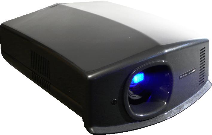
15 4.0 GETTING STARTED 4.0 GETTING STARTED 4.1 General View Front side Optical Lens Air Inlet Front IR sensor Air Inlets: see Air-Flow and Space Requirements, page 8. Rear side Operating LEDs Lamp trap Operating buttons Back IR sensor Operating LEDs: see section 4.3, page 17 for more details. Operating and Navigation buttons described in section 4.4, page 18. Lamp trap: see Procedure for Lamp Replacement, page 34 for more details about lamp replacement. Input Panel side Input Panel Main Power: connect the power cord as shown below. Input Panel: connect your video source to the correct input. Main Power R Blackwing User Manual 15
16 4.0 GETTING STARTED 4.2 Connecting the Power Cord Before plugging in the Power Cord, ensure that all devices have been connected. Connect the power cord to the power input terminal of the projector. CAUTION AGAINST FIRE AND ELECTRIC SHOCK Since the power consumption of this unit is high, insert the power plug directly into a wall outlet. When not using devices, remove the power plug from the wall outlet. Do not use power cords for connection other than specified. Do not use a power voltage different from that which is indicated. Do not cut, tear or modify the power cords. Also, do not place a heavy object on, heat or stretch the power cords as this may cause damage to the cords. Do not insert or pull plugs with a wet hand. 16 R Blackwing User Manual
17 4.0 GETTING STARTED 4.3 Operating LEDs STANDBY/ON (green/red LED) LAMP (orange LED) WARNING (red LED) BACK INPUT HIDE OK MENU Operating LED ID STANDBY/ON (green or red) LAMP (orange) WARNING (red) Blinking Description 1 red Unit is in standby mode 2 green Unit is in operate mode (during projection) 3 blinking green - - Yes Unit is in operate mode, but HIDE is ON. Press again on HIDE button to obtain a picture. 4 blinking red - - Yes Unit is in cooldown mode. (switching off) 5/6 - orange - - Lamp time has reached 2900 hours, prepare to replace the lamp before 3000 hours. CAUTION When in Cool Down mode, do not pull out the plug from the outlet. Also, do not block the air inlets/exhaust vents by standing the projector on its end or laying it on its side. R Blackwing User Manual 17
18 5.0 CONNECTIONS 4.4 Operating and Navigation Buttons Left - right Hide display OK Input source BACK Back INPUT HIDE OK Power button MENU Menu Up - down Button Hide display Input source Power button Description To temporary hide the picture. To switch input source. To turn On or Off the projector. Up - down - left - right OK (Enter) Back Menu To navigate into On Screen Display (OSD) Menu. To select or to confirm action. To return to previous menu or cancel action. To display On Screen Display (OSD) Menu. 5.0 CONNECTIONS This unit can be connected to any compatible devices using the available inputs listed below: 2x HDMI revision 1.3 with HDCP 1x Video 1x S-Video 1x Component (YPbPr / RGB / SCART) 1x 12 volt Trigger 1x RS-232 1x PC - VGA (sub D-15) available for BW3 only. The RS-232 terminal port can be used for automation. For audio output, connect your audio video source to an amplifier. This unit features a 12 Volt trigger output that can be used to control external device in On/Off mode or together with the optional anamorphic lens systems. 18 R Blackwing User Manual
19 5.0 CONNECTIONS 5.1 Connecting a device to the projector HDMI 1 RS-232 HDMI 2 S-Video Video VGA (Sub D-15) (BW3 only) YPbPr or RGB or SCART HDMI1, HDMI2 Input VGA (BW3 only) RS-232 (*) S-Video Video YPbPr or RGB or SCART (EU) Device HDMI or DVI-D sources: Blu-Ray Disc player, DVD-player with HDMI, Game Console, Computer with DVI-D output. Computer (VGA output), Multimedia box for BW3 only. Automation Device, Control Device or Computer with RS-232* DVD-Player, Game Console, digital camera, video camera DVD-Player, Computer video, Game Console (SD), digital camera, video camera. DVD-Player, HDTV Receiver, Game Console (SD or HD), DVB-T receiver, Multimedia box, Analog Camera. In order to use a SCART device* (Europe) on the Component input, you must use cable sold separately and configure it into the projector menu. Make sure to use a certified HDMI cable, especially when the distance between the different devices are longer than 5 meters. If it is the case, the use of a split system or optical fiber cable is highly recommended. (*) USING RS-232 WITH A COMPUTER The RS-232 Control and Automation may require specific software and tools. See RS-232 input and IR Codes, page 37 for more details on RS-232 cabling and protocol. For input resolution and refresh rates, check the PC compatible signals, page 41. R Blackwing User Manual 19
20 5.0 CONNECTIONS 5.2 Connecting a SCART device SCART CONNECTING A SCART DEVICE This unit can be connected to a SCART device using a SCART to RGB+Sync cable. Once connected, select the COMP. input as active input. Then browse into the projector menu to Input Signal > COMP. and select SCART option. 5.3 Caution when connecting a device CAUTION! Prior to connecting any device to this unit, switch the projector in standby mode Never connect a HDMI source to this unit when the projector is in operate mode. The HDMI termination is a selfpowered connection and can cause electric discharges. 20 R Blackwing User Manual
21 6.0 MENU AND PICTURE SETTING 6.1 Menu Structure 6.0 MENU AND PICTURE SETTING MAIN MENU SUBMENU AVAILABLE OPTIONS Picture Adjust Picture Mode (Movies) Cinema1 (Vivid HDTV) Cinema2 (SF movies or anims) Cinema3 (Video programs) Natural (Concerts) Stage (bright lightning) Dynamic User1 User2 (BW3 only) TH-PRO Contrast Brightness Color Tint Color Temp. 5800K 6500K 7500K 9300K High Bright Custom1 Custom2 Custom3 Gamma Normal A B C D Custom1 Custom2 Custom3 Advanced Sharpness Detail Enhancement Noise Reduction (SD only): DNR 0-16 MNR 0-16 BNR On, Off CTI (SD only) Off, Low, Mid, High Color Management (BW3 only) Off Custom1 Custom2 Custom3 Crystal Motion Off, Low, High Lens Aperture (R ) 1-3 (R ) Reset Profile Confirm R Blackwing User Manual 21
22 6.0 MENU AND PICTURE SETTING Input Signal HDMI inputs Input Auto (16-235) Standard (0-255) Enhanced Color Space Auto YCbCr(4:4:4) YCbCr(4:2:2) RGB Control with HDMI (CEC) On, Off COMP. input Color Space YCbCr RGB SCART Video / S-Video inputs NTSC Setup Level 0 IRE 7.5 IRE Color System Auto NTSC NTSC 4.43 PAL PAL-M PAL-N SECAM PC input (BW3 only) Auto Alignment Tracking Phase Picture position Hor., Vert. Picture Position Horizontal Vertical Aspect (Video only) 4:3 16:9 Zoom Aspct (Computer only) Auto Just Full V-stretch On, Off Over Scan (SD only) (2.5%) On Off Mask (HD only) 2.5% 5% Off Film Mode (only 480i, 576i, 1080i) Auto, Film, Off Installation Lens Control Focus Zoom Shift Test Pattern On, Off Lock On, Off Pixel Adjust horiz. Red 1-7 horiz.green 1-7 horiz.blue 1-7 vert. Red 1-5 vert. Green 1-5 vert. Blue 1-5 Installation Style Front Ceiling Mount (Front) Rear Ceiling Mount (Rear) Keystone Horizontal, Vertical Screen Adjust Off A B C 22 R Blackwing User Manual
23 6.0 MENU AND PICTURE SETTING Display Setup Back Color Blue, Black Menu Position Menu Display Line Display (input setting) Source Display (active input) Logo Language select position 15sec, On 5sec, Off On, Off On, Off Select between 12 languages Function Lamp Power Normal High Information Trigger Test Pattern Off Timer High Altitude Mode Input Image Connector Input Source name PC Resolution PC H Freq. PC V Freq. Deep Color Depth Lamp use Off On (Power) On (Vstretch) Select between 6 Test Patterns 1 hour, 2 hours, 3 hours, 4 hours On, Off R Blackwing User Manual 23
24 6.0 MENU AND PICTURE SETTING 6.2 Picture Adjust menu Picture Mode Three preset picture modes are available and they can be applied to any input. A picture mode retains the Picture adjustments: Cinema1 setting is best suited for general movie watching. Cinema2 setting is optimized for vivid based in HDTV standards. Best to be used with animation or vivid movies. Cinema3 setting brings a cool tone to the picture. Best used with for sciences fiction movies. Natural setting for natural hues and tones. Best for dramas and video. Stage setting for live concerts or stage performances. Dynamic setting to be used when the room cannot be completely dark. TH-PRO (BW3 only) setting to obtain a non over-saturated colors in a dark environment. Optimized for movie projection. Additionally, you can define 2 user modes to finely tune the projector to your video source and the ambient light. User1 User2 Contrast The contrast function is used to adjust the contrast between the light and dark areas of the displayed image. A correct contrast setting is important for good image reproduction. Adjust the Contrast value between -50 and 50. Brightness The brightness function is used to adjust the overall light output. Adjust the Brightness value between -50 and 50. Color The Color function (or Saturation) is used to adjust the color saturation levels. Adjust the Color value between -50 and 50. Tint The hue function is used to adjust the color tint to obtain true color reproduction. Adjust the Tint value between -50 (more red) and 50 (more green). Color Temperature Color temperature stands for the spectral properties of a light source. Low color temperature implies warmer ambiance (more yellow/red) while high color temperature implies a colder light (more blue). This setting can be set to: 5800K: warm colors 6500K. neutral colors, match current HDTV and Blu-Ray encoding. 7500K: brings a bluish tinge to the picture, best suited for night scenes. 9300K: cold picture best suited for computer and graphics. High Bright: select the brightest output mode available. Custom1 Custom2 Custom3 A Custom setting allows a fine adjustment of a Color Temperature by selecting in the Correction Value tab 5800K, 6500K, 9300K or High Bright. Adjust the Gain values (bright part) and Offset values (dark part) for each color Red, Green and Blue. Accurate color temperature may require professional tools such as dedicated software and colormeter. Wait at least 20 minutes after startup before modifying the picture settings. Gamma Gamma is the relationship between the color values of the data and the color values displayed. The Gamma coefficient makes it possible to adjust the brightness of the midtones only without affecting the very bright and very dark areas. If gamma is set too high, middle tones appear too dark. If it's set too low, middle tones appear too light. The Gamma correction factor can be set to: 24 R Blackwing User Manual
25 6.0 MENU AND PICTURE SETTING Normal: Standard tones Gamma A: rich dark tones. Gamma B: for film and movie projection. Gamma C: for film and movie projection with more detailed blacks than setting B. Gamma D: this setting is recommended for bright midtones and Computer like projection. Custom1 Custom2 Custom3 The Custom data can be set to: Correction Value: a unique value that will act as a gamma coefficient between 1.8 and 2.6. Gamma Adjustment: the gamma curve can be adjusted for each color Red, Green and Blue. Copy: copy the adjusted values to temporal memory. Paste: paste values stored in memory to current profile. Reset: reset to the default 2.2 gamma coefficient. Gamma Adjustment can be copied from all modes. Paste can only be used for Custom modes. Advanced Sharpness The Sharpness function is used to adjust the image sharpness of the picture. Adjust the Sharpness value between 0 (soft) and 100 (sharper) Detail Enhancement Detail Enhancement function is used to improve the picture quality. You can set it from -50 to Noise Reduction (SD video only) DNR: Digital Noise Reduction. You can set it from 0 up to 16 to reduce the image noise. MNR: Mosquito Noise Reduction function is used to reduce the Mosquito noise on the picture, generally found in compressed digital video signals such as television broadcast or encoded movies. Adjust the MNR value from 0 up to 16 to reduce the typical broadcast picture mosquito noise BNR: Block Noise Reduction uses a large portion of the picture to reduce the digital noise, this ensures a higher quality filter. Adjust the BNR value to On or Off CTI (SD video only) Color Transition Improvement. Set it to Off, Low, Middle or High to reduce the color smear (color contour correction). Caution: this function may alter the original picture chrominance Color Management (TSL adjustments for BW3 only) The Color Management gives the installer an unique calibration ease with the integrated Color Adjustment menu: each primary and secondary color can be independently calibrated to obtain a precise color balance in a snap. Adjust the Red, Green, Blue, Yellow, Cyan and Magenta Tints, Saturations and Luminances and store them into Custom1, Custom2 or Custom3 profiles Crystal Motion Drive (120Hz) The Crystal Motion function uses a 120Hz video processing to render a smooth and clear motion for movies shot at 24Hz or HD movies at 60Hz. Set the correct level between low and high for 1080p24Hz movies or Film mode input to obtain a clear image. Lens Aperture The lens is equipped with a variable electronic aperture. This function is used to optically adjust the light output depending on the viewing conditions and the light ambiance. Adjust from the correct aperture from partially closed to fully opened. Reset R Blackwing User Manual 25
26 6.0 MENU AND PICTURE SETTING Reset values to their default settings. 6.3 Input Signal menu HDMI Inputs This menu is available if the selected active input is HDMI1 or HDMI Input Auto: The input dynamic range is automatically detected and configured. Standard: Force dynamic range output to Enhanced: Force dynamic range output to Color Space Auto: The source color space is automatically detected and configured. YCbCr(4:4:4): Set color space to YCbCr 4:4:4. YCbCr(4:2:2): Set color space to YCbCr 4:2:2. RGB: Set color space to RGB 4:4: Control with HDMI (CEC) Off: By default the CEC communications are disabled. On: Enables CEC communications to be sent to the projector through HDMI cable. CEC: Consumer Electronic Control Component This menu is available if the selected active input is Component. Y Pb/Cb Pr/Cr: Select this option if the COMP. input is connected to a component video signal. RGB: Select this option if the COMP. input is used with a RGB video source. SCART: Select this option if the COMP. and VIDEO inputs are used together to receive RGB+Sync signals from a European SCART source. Video / S-Video This menu is available if the selected active input is either Video or S-Video NTSC Setup level This function can adjust the black level of the signal to 7.5 IRE instead of 0IRE. 7.5 IRE is widely used for NTSC standard Color System This function allows a manual selection of the color system to be used between NTSC, NTSC4.43, PAL, PAL-M, PAL-N and SECAM. The default setting is Auto. When Auto is selected, the input format is automatically detected and the correct color system is applied. PC (BW3 only) This menu is available if the selected active input is PC (Sub-D15) input. Auto Alignment: Automatically adjusts Tracking, Phase and Picture Position Tracking: Adjust the horizontal size and display area of the picture. Phase: Adjust flickering and blurred pictures. Picture Position: Adjust the display position of the picture. Picture Position Depending on your source, you may find that the picture should be adjusted into the screen, adjust the horizontal and vertical position of the picture into the screen. Some signals may not be fully displayed, adjust this setting properly when necessary. Aspect Ratio When watching a movie or video program, you can manually set the desired aspect ratio to fill your screen. Select the correct aspect ratio depending on your source: For Video sources 26 R Blackwing User Manual
27 6.0 MENU AND PICTURE SETTING 4:3. The original source is considered as 4:3 format. Generally SDTV broadcasts and entertainments. 16:9. The picture size is 16:9, generally most recent DVDs, Blu-Ray discs and HDTV broadcasts. Zoom. The zoom function is useful to zoom in the picture and eliminate black bars SD or HD SOURCE ASPECT RATIO SDTV 4:3 (full frame) 4:3 16:9 Zoom SDTV 4:3 (with black bands) 4:3 16:9 Zoom SDTV 4:3 (compatible 16:9) 4:3 16:9 Zoom NA HDTV (format 16:9) 4:3 16:9 NA HD signals AR 2.35 or :3 16:9 Aspect Ratio applied to different source formats For PC sources Auto. Zoom the picture to fill either the screen height or the screen base which ever happens first. Just is a 1:1 mode, pixel to pixel mapping, no scaling. Full. Stretch the picture full screen. Sub-D15 or HDMI ASPECT RATIO SOURCE XGA (4:3) Auto Just Full SXGA (4:3) Auto Just Full 1280x768 Auto Just Full Aspect Ratio applied to PC-signals. V-Stretch (for Video sources) This setting is available only for SD and HD signals. If you enable this function, the original picture is stretched to R Blackwing User Manual 27
28 6.0 MENU AND PICTURE SETTING fit an installation with anamorphic lens. The picture fills completely the projector panels, using the maximum available resolution for aspect ratio movies. SD or HD SOURCE V-STRETCH SDTV (2.35) 16:9, Off On HDTV (2.35) 16:9, Off On V-Stretch applied to SD and HD sources. Over Scan (only SD) and Mask (only HD) The standard definition (SD) signals generally use a frame which is larger than the visible portion of the picture, this is to ensure a larger compatibility with old-fashioned scanning devices such as CRT-televisions. Depending on your source, you may enable or disable this feature to hide the outer area of the picture. The Mask function available for high definition (HD) signals can hide the unexpected scaling artefacts generally found in HDTV broadcast program. You can set it to Off, 2.5% or 5%. Film Mode (only 480i, 576i, 1080i) To provide a better video quality, you can manually set the Film Mode cadence when necessary. Set it from default Auto setting to Film to force the Film Mode or set it to Off to disable it. This function is only available for interlaced input signals: 480i, 576i and 1080i. 6.4 Installation Menu Lens Control This menu gives access to the control of the lens. Browse into this menu to adjust: Focus Adjust the lens focus to obtain a clear picture Zoom Adjust the lens zoom to fill the screen with the picture Shift Adjust lens shift to center the picture into the screen Image Pattern If set to On, an internal pattern will be generated to adjust the current setting. If you want to use an external generator, turn this option to Off Lock Once the Lens is correctly set, you may lock this setting menu by turning the Lens control Lock to On. Any attempt to access the Lens control menu will lead to the display of a warning message. Pixel Adjust This menu allows a fine adjustment of the red, green and blue panels alignment. Horizontal adjustment moves the selected color to the right, vertical adjustment moves it up. Horizontal Red (1 to 7) Horizontal Green (1 to 7) Horizontal Blue (1 to 7) Vertical Red (1 to 5) Vertical Green (1 to 5) 28 R Blackwing User Manual
29 6.0 MENU AND PICTURE SETTING Vertical Blue (1 to 5) Installation Style Flip the image to the left or right, up or down according to the projection state of the projector: Front, Ceiling Mount (F), Rear or RearCeiling mount (R) Keystone Compensate for trapezoidal distortion caused by installation. Independently to the screen orientation, make sure that the projector is not tilt more than 5% left/right and 15% up/down. Screen Adjust This setting corrects the color balance derived from the reflective characteristics of the screen without altering the global picture settings. You may select: Off: No modification Mode A: slightly reddish Mode B: slightly greenish Mode C: slightly bluish 6.5 Display Setup Menu Back Color Configures the screen color displayed when there is no active input. Set to Blue or Black. Menu Position Upper left, Upper right, Center, Lower right, Lower left. Menu Display 15sec: Display menu for 15 seconds before fade out. On: Always display menu. Line Display 5sec: Display the input settings for 5 seconds after input selection. Off: Don t display Source Display On: Display the source of the input signals after input. selection Off: Don t display. Logo On: Display logo during startup for 5 seconds. Off: Don t display. Language Choose the OSD language between: English, Japanese, German, Spanish, Italian, French, Portuguese, Dutch, Swedish, Norvegian, Russian and Chinese. 6.6 Function Menu Lamp Power The Lamp Output function is used to configure the light output of the lamp. Select Normal to set the lamp to 150W or High, 200W. To avoid any damage to the lamp, you can t changed the lamp power within 90 seconds from the projector startup or 60 seconds after lamp power change. Trigger The 12V trigger output can be used to control any 12V remoted compatible devices such as motorized screens or anamorphic kits: The 12V trigger output is 12Vcc, 100mA. Select the trigger output behavior: Off: 12V trigger voltage state is always low. On (power):12v trigger state is high when the projector is powered ON. On(V-Stretch): 12V trigger is high only when V-Stretch is active. To be used with Anamorphic kits or 2.35 motorized screen. R Blackwing User Manual 29
30 6.0 MENU AND PICTURE SETTING Test Pattern Display 6 types of test patterns. For checking the color condition and tone, and the pixels size. Use whenever necessary. Off-Timer You can configure this automatic power Off function that will switch off the projector when there is no operation and no signal. Choose the duration of the timer between: Off, 1 hour, 2 hours, 3 hours and 4 hours. High Altitude Mode Select this when the projector is in a location of low atmospheric pressure. On or Off 6.7 Information Menu Input Source Displays the active video input. Source Displays the type of the current video input signal. If PC input is selected, this item cannot be displayed. Resolution If the active input is PC input., its resolution is displayed. H. Frequency In the case of PC signal, the horizontal frequency is displayed. V. Frequency In the case of PC signal, the vertical frequency is displayed. Deep Color Display the bit depth (color depth) of the video signals input from the HDMI terminals. Deep Color is not displayed for YCbCr 4:2:2 signals. Lamp Time Displays the accumulated hours of usage of the lamp. 6.8 Expert Calibration Expert Calibration is accessed using RS-232 or programmable IR-RCU. You can set a Calibration Profile 30 R Blackwing User Manual
31 7.0 ANAMORPHIC LENS 7.0 ANAMORPHIC LENS 7.1 Optional 2.35 CineMax and 2.35 THEATRE Concept The Blackwing centralizes the controls and automation commands for both the 2.35 CineMax and the 2.35 THEATRE Concept for a unique, versatile and unexpectedly simple to operate 2.35:1 theatre experience using an Anamorphic Lens. Integrated Constant Image Width scaler. Dedicated menu to program the 12V Trigger output. 7.2 Using the Remote Control Unit. STAND BY ON INPUT Select active input HDMI 1 HDMI 2 COMP. VIDEO S-VIDEO LENS ASPECT HIDE TEST LIGHT Select the correct Aspect Ratio MENU BACK PICTURE MODE CINEMA 1 CINEMA 2 CINEMA 3 NATURAL STAGE DYNAMIC USER1 USER2 GAMMA C.TEMP LENS. AP. PIC. ADJ. [ASPECT] ratio button Blackwing RCU and quick access to THEATRE Mode features Aspect 4:3 Aspect 16:9 Zoom When you press sequentially the [ASPECT] button, the aspect mode rotation is 4:3, 16:9, Zoom then back to 4:3. R Blackwing User Manual 31
ASSEMBLY AND CALIBRATION
 CineMax Kit ASSEMBLY AND CALIBRATION www.cineversum.com Ref: T9003000 Rev: 01 Part. No.: R599766 Changes CineVERSUM provides this manual as is without warranty of any kind, either expressed or implied,
MK2010 ASSEMBLY AND CALIBRATION
 Cinemax Kit for Blackwing MK2010 ASSEMBLY AND CALIBRATION www.cineversum.com Ref: T9005500 Rev: 01 Part. No.: R599783 Changes Cineversum provides this manual as is without warranty of any kind, either
USER MANUAL. 22" Class Slim HD Widescreen Monitor L215DS
 USER MANUAL 22" Class Slim HD Widescreen Monitor L215DS TABLE OF CONTENTS 1 Getting Started Package Includes Installation 2 Control Panel / Back Panel Control Panel Back Panel 3 On Screen Display 4 Technical
USER MANUAL. 27 Full HD Widescreen LED Monitor L27ADS
 USER MANUAL 27 Full HD Widescreen LED Monitor L27ADS TABLE OF CONTENTS 1 Getting Started 2 Control Panel/ Back Panel 3 On Screen Display 4 Technical Specs 5 Care & Maintenance 6 Troubleshooting 7 Safety
USER MANUAL. 27 Full HD Widescreen LED Monitor L270E
 USER MANUAL 27 Full HD Widescreen LED Monitor L270E TABLE OF CONTENTS 1 Getting Started 2 Control Panel/ Back Panel 3 On Screen Display 4 Technical Specs 5 Care & Maintenance 6 Troubleshooting 7 Safety
28 4K LED monitor. User Manual M284K
 28 4K LED monitor User Manual M284K CONTENTS Safety Information... 2 What s included..... 4 Getting Started....... 8 Troubleshooting.... 14 Specification.... 15 2 of 15 SAFETY INFORMATION Read these instructions
USER MANUAL Full HD Widescreen LED Monitor L215IPS
 USER MANUAL 21.5 Full HD Widescreen LED Monitor L215IPS TABLE OF CONTENTS 1 Getting Started 2 Control Panel/ Back Panel 3 On Screen Display 4 Technical Specs 5 Care & Maintenance 6 Troubleshooting 7 Safety
Changes. Copyright. Guarantee. Trademarks. 2 R Dream E User Manual
 Changes DreamVision provides this manual as is without warranty of any kind, either expressed or implied, including but not limited to the implied warranties or merchantability and fitness for a particular
USER MANUAL Full HD Widescreen LED Monitor L215ADS
 USER MANUAL 21.5 Full HD Widescreen LED Monitor L215ADS TABLE OF CONTENTS 1 Getting Started 2 Control Panel/ Back Panel 3 On Screen Display 4 Technical Specs 5 Care & Maintenance 6 Troubleshooting 7 Safety
AUTO - SCANNING WITH DIGITAL CONTROL LCD COLOR MONITOR FS-L1903C. User manual (Rev.01) SMITHS HEIMANN
 SMITHS HEIMANN") AUTO - SCANNING WITH DIGITAL CONTROL LCD COLOR MONITOR FS-L1903C User manual (Rev.01) SMITHS HEIMANN www.smithsdetection.com Table of Contents Safety Instructions... 5 Accessories... 8 Power Connections...
AUTO - SCANNING WITH DIGITAL CONTROL LCD COLOR MONITOR FS-L1903C User manual (Rev.01) SMITHS HEIMANN www.smithsdetection.com Table of Contents Safety Instructions... 5 Accessories... 8 Power Connections...
PL2410W LCD Monitor USER'S GUIDE.
 PL2410W LCD Monitor USER'S GUIDE www.planar.com Content Operation Instructions...1 Safety Precautions...2 First Setup...3 Front View of the Product...4 Rear View of the Product...5 Quick Installation...6
PLL1920M LED LCD Monitor
 PLL1920M LED LCD Monitor USER'S GUIDE www.planar.com Content Operation Instructions...1 Safety Precautions...2 First Setup...3 Front View of the Product...4 Rear View of the Product...5 Installation...6
USER MANUAL Full HD Widescreen LED Monitor L236VA
 USER MANUAL 23.6 Full HD Widescreen LED Monitor L236VA TABLE OF CONTENTS 1 Getting Started 2 Control Panel/ Back Panel 3 On Screen Display 4 Technical Specs 5 Care & Maintenance 6 Troubleshooting 7 Safety
17 19 PROFESSIONAL LCD COLOUR MONITOR ART
 17 19 PROFESSIONAL LCD COLOUR MONITOR ART. 41657-41659 Via Don Arrigoni, 5 24020 Rovetta S. Lorenzo (Bergamo) http://www.comelit.eu e-mail:export.department@comelit.it WARNING: TO REDUCE THE RISK OF FIRE
 Register your product and get support at www.philips.com/welcome SWS3435S/27 SWS3435H/37 EN User manual Contents 1 Important 4 Safety 4 English 2 Your SWS3435 6 Overview 6 3 Installation 7 Connect the
HD Digital Set-Top Box Quick Start Guide
 HD Digital Set-Top Box Quick Start Guide Eagle Communications HD Digital Set-Top Box Important Safety Instructions WARNING TO REDUCE THE RISK OF FIRE OR ELECTRIC SHOCK, DO NOT EXPOSE THIS PRODUCT TO RAIN
Monochrome Video Monitors
 Instructions for Use Monochrome Video Monitors En F D E NL I LTC 2009 LTC 2012 LTC 2017 Philips Communication & Security Systems GB F D E NL I Instructions for Use...1.1 Mode d emploi...2.1 Bedienungsanleitung...3.1
USER MANUAL. 28" 4K Ultra HD Monitor L28TN4K
 USER MANUAL 28" 4K Ultra HD Monitor L28TN4K TABLE OF CONTENTS 1 Getting Started 2 Control Panel/ Back Panel 3 On Screen Display 4 Technical Specs 5 Care & Maintenance 6 Troubleshooting 7 Safety Info &
CAUTION RISK OF ELECTRIC SHOCK NO NOT OPEN
 Evolution Digital HD Set-Top Box Important Safety Instructions 1. Read these instructions. 2. Keep these instructions. 3. Heed all warnings. 4. Follow all instructions. 5. Do not use this apparatus near
USER MANUAL. 27" 2K QHD LED Monitor L27HAS2K
 USER MANUAL 27" 2K QHD LED Monitor L27HAS2K TABLE OF CONTENTS 1 Getting Started 2 Control Panel/ Back Panel 3 On Screen Display 4 Technical Specs 5 Troubleshooting 6 Safety Info & FCC warning 1 GETTING
PLL2210MW LED Monitor
 PLL2210MW LED Monitor USER'S GUIDE www.planar.com Content Operation Instructions...1 Safety Precautions...2 First Setup...3 Front View of the Product...4 Rear View of the Product...5 Quick Installation...6
TFT LCD MONITOR USER MANUAL. L80AP and L101AP
 TFT LCD MONITOR USER MANUAL L80AP - 8.0 and L101AP - 10.1 Table Of Contents Table of contents/ Warning.... 2 Precautions...3 About this user manual and products / Items included in the delivery..... 4
LCD VALUE SERIES (32 inches)
") LCD VALUE SERIES (32 inches) http://www.orionimages.com All contents of this document may change without prior notice, and actual product appearance may differ from that depicted herein 1. SAFETY INSTRUCTION
LCD VALUE SERIES (32 inches) http://www.orionimages.com All contents of this document may change without prior notice, and actual product appearance may differ from that depicted herein 1. SAFETY INSTRUCTION
DCL9AW. User Manual. English
 DCL9AW User Manual English PRECAUTIONS Information for users applicable in European Union countries 1 Information for users applicable in United States of America 1 Installation 1 Power connection 1 Maintenance
Evolution Digital HD Set-Top Box Important Safety Instructions
 Evolution Digital HD Set-Top Box Important Safety Instructions 1. Read these instructions. 2. Keep these instructions. 3. Heed all warnings. 4. Follow all instructions. 5. Do not use this apparatus near
Winmate Communication INC.
 20.1 Military Grade Display Model: R20L100-RKA2ML User s Manual Winmate Communication INC. May, 2011 1 IMPORTANT SAFETY INSTRUCTIONS Please read these instructions carefully before using the product and
DC162 Digital Visualizer. User Manual. English - 1
 DC162 Digital Visualizer User Manual English - 1 Table of Contents CHAPTER 1 PRECAUTIONS... 5 CHAPTER 2 PACKAGE CONTENT... 7 CHAPTER 3 PRODUCT OVERVIEW... 8 3.1 PRODUCT INTRODUCTION... 8 3.2 I/O CONNECTION...
Quick Reference Guide
 Multimedia Projector Quick Reference Guide MODEL 103-011100-01 Projection lens is optional. English Use this book as a reference guide when setting up the projector. For detailed information about installation,
Acer LCD TV AT2001 User's Guide
 Acer LCD TV AT2001 User's Guide Copyright 2005. Acer Incorporated. All Rights Reserved. Acer AT2001 User' s Guide Original Issue: May 2005 Acer and the Acer logo are registered trademarks of Acer Incorporated.
SIM 5 series Lamp Kit
 SIM 5 series Lamp Kit Installation manual R9841842 R59770361/01 04/12/2013 Factory: Barco nv, Simulation Division Noordlaan 5, B-8520 Kuurne Phone: +32 56.36.82.11 Fax: +32 56.36.84.86 Support: www.barco.com/esupport
PXL2760MW LED LCD Monitor
 PXL2760MW LED LCD Monitor USER'S GUIDE www.planar.com Content Operation Instructions...1 Safety Precautions...2 Package Overview...3 First Setup...4 Front View of the Product...5 Rear View of the Product...6
2.0 Wall Mount TV Soundbar Instruction Manual
 8010275 2.0 Wall Mount TV Soundbar Instruction Manual Read all of the instructions before using this soundbar and keep the manual in a safe place for future reference. Safety Information CA UT IO N RISK
PLL2710W LED LCD Monitor
 PLL2710W LED LCD Monitor USER'S GUIDE www.planar.com Content Operation Instructions...1 Safety Precautions...2 Package Overview...3 First Setup...4 Front View of the Product...5 Rear View of the Product...6
ATTACHING & REMOVING THE BASE
 TV53DB ATTACHING & REMOVING THE BASE 1. To install or remove the neck, screw in or remove the 4 screws indicated in the picture. 2. To install the base, place the display unit flat on a table. Afterwards
DM-1CH SD DVB-T MODULATOR INSTRUCTION MANUAL
 DM-1CH SD DVB-T MODULATOR INSTRUCTION MANUAL 2. Caution Statements and Table of Contents Table of Contents 2. Caution Statements and Table of contents 3. Important Safety Instructions 4. Important Safety
9" B/W MONITOR CEM-09/09A-2 12" B/W MONITOR CEM-12/12A-2 OPERATION MANUAL
 9" B/W MONITOR CEM-09/09A-2 12" B/W MONITOR CEM-12/12A-2 OPERATION MANUAL CONTENTS PRECAUTIONS FOR USE AND INSTALLATION IMPORTANT SAFEGAURDS SAFETY INSTRUCTIONS INSTRUCTION MANUAL CLASS B COMPUTING DEVICES
CU103 User Manual. Contents
 [Note] The Photos of Light Engine and Control Unit in this manual are for reference only. The items may be different in actual package. Contents 1. PRECAUTIONS... 2 2. PACKAGE CONTENT... 4 3. PORT DESCRIPTION...
Wireless 4 Channel Receiver with 2 Night Vision cameras
 Wireless 4 Channel Receiver with 2 Night Vision cameras Instruction Manual English Version 2.0 MODEL: SHS-4WLS www.lorexcctv.com Copyright 2006 LOREX Technology Inc. Thank you for purchasing the SHS-4WLS.
SAFETY WARNINGS AND GUIDELINES
 SAFETY WARNINGS AND GUIDELINES Please read this manual thoroughly, paying extra attention to these safety warnings and guidelines: Do not expose this monitor to water or moisture of any kind. Do not handle
LTC 113x & LTC123x FlexiDome Series Fixed Dome Cameras
 LTC 113x & LTC123x FlexiDome Series Fixed Dome Cameras Eng Installation Instructions F D E NL I IMPORTANT SAFEGUARDS 1. Read Instructions All the safety and operating instructions should be read before
22" Touchscreen LED Monitor USER'S GUIDE
 22" Touchscreen LED Monitor USER'S GUIDE Content Operation Instructions...1 Unpacking Instructions...2 Safety Precautions...2 Front View of the Product...3 Rear View of the Product...4 Quick Installation...5
4 PORT HDMI SWITCH
 4 PORT HDMI SWITCH 1518896 IMPORTANT SAFEGUARDS OF HDMI SWITCH PRODUCTS PLEASE READ CAREFULLY THE FOLLOWING SAFEGUARDS THAT ARE APPLICABLE TO YOUR EQUIPMENT 1. Read instructions - All the safety and operating
VITEK VTM-TLM191 VTM-TLM240
 VTM-TLM191 VTM-TLM240 19 & 24 Professional LED Monitors with HDMI, VGA, and Looping BNC VITEK FEATURES 19 & 24 Wide Screen LED Display Panel HDMI, VGA, and Looping BNC Composite Video Inputs & Stereo Audio
Register your product and get support at SDV5122/27. EN User manual
 Register your product and get support at www.philips.com/welcome SDV5122/27 User manual Contents 1 Important 4 Safety 4 Notice for USA 5 Notice for Canada 5 Recycling 6 English 2 Your SDV5122 7 Overview
900-Lumen Portable LED Projector Part #: User manual
 900-Lumen Portable LED Projector Part #: 21797 User manual 900-Lumen LED Projector Manual Page 2 of 14 900-Lumen LED Projector Manual Page 3 of 14! SAFETY WARNINGS AND CAUTIONS WARNING: To reduce the risk
User Manual TL-2X1-HDVC 2x1 HDMI & VGA Switcher with Control All Rights Reserved Version: TL-2X1-HDVC_160630
 User Manual TL-2X1-HDVC 2x1 HDMI & VGA Switcher with Control All Rights Reserved Version: TL-2X1-HDVC_160630 Preface Read this user manual carefully before using this product. Pictures shown in this manual
Camera 220C Document Camera User s Guide
 Camera 220C Document Camera User s Guide #401-220C-00 Table of Contents TABLE OF CONTENTS... 0 TABLE OF CONTENTS... 1 COPYRIGHT INFORMATION... 2 CHAPTER 1 PRECAUTIONS... 3 CHAPTER 2 PACKAGE CONTENT...
Wired to Wireless Camera Converter
 Wired to Wireless Camera Converter Instruction Manual English Version 1.0 MODEL: WL401BNC www.lorexcctv.com Copyright (c) 2006 LOREX Technology Inc. Thank you for purchasing the 2.4 GHz Wireless Camera
10.4 Dual Rack Mount TFT-LCD Monitor INSTRUCTION MANUAL. Please read this manual thoroughly before use. Keep it handy for future reference.
 10.4 Dual Rack Mount TFT-LCD Monitor INSTRUCTION MANUAL Please read this manual thoroughly before use. Keep it handy for future reference. Document Number: V531-LD100-000 Ver. 07/2010 * * * WARNING * *
2.4 GHz WIRELESS VIDEO SENDER SYSTEM MODEL: VS6234
 2.4 GHz WIRELESS VIDEO SENDER SYSTEM MODEL: VS6234 Please read this manual thoroughly before operating this system OPERATING INSTRUCTIONS 03/02 1 SAFETY INSTRUCTIONS CAUTION! RISK OF ELECTRIC SHOCK. DO
User Manual TL-2X1-HDV 2x1 HDMI & VGA Switcher All Rights Reserved Version: TL-2X1-HDV_160630
 User Manual TL-2X1-HDV 2x1 HDMI & VGA Switcher All Rights Reserved Version: TL-2X1-HDV_160630 Preface Read this user manual carefully before using this product. Pictures shown in this manual are for reference
18.5, 21.5, 23.8 & 27 Widescreen LED Security Monitors LED22 USER GUIDE
 LED18 / LED22 / LED24 / LED27 18.5, 21.5, 23.8 & 27 Widescreen LED Security Monitors LED27 LED24 LED22 LED18 USER GUIDE 3625 Cincinnati Avenue, Rocklin, CA 95765 855-388-7422 www.northernvideo.com Rev.
DLA-HD2KU/DLA-HD2KE HOME THEATER PROJECTOR INSTRUCTIONS
 HOME THEATER PROJECTOR DLA-HD2KU/DLA-HD2KE INSTRUCTIONS ON OFF FOCUS LIGHT TEST MENU PRESET HIDE For Customer Use: Enter below the Serial No. which is located on the side panel of the cabinet. Retain this
28 & 32 & 40 & 55 & 65 & 84-INCH TFT-LCD 4K MONITOR
 28 & 32 & 40 & 55 & 65 & 84-INCH TFT-LCD 4K MONITOR INSTRUCTION MANUAL Please read this manual thoroughly before use, and keep it handy for future reference. TABLE OF CONTENTS 1, General information...
Congratulations on your mcable purchase! The mcable delivers the best possible picture to your HD or 4K TV by up-converting 480p and 720p content to
 1 USER GUIDE Congratulations on your mcable purchase! The mcable delivers the best possible picture to your HD or 4K TV by up-converting 480p and 720p content to 1080p, up-converting 1080p content to near-native
HD Digital MPEG2 Encoder / QAM Modulator
 HD Digital MPEG2 Encoder / QAM Modulator YPrPb VGA In QAM Out series Get Going Guide ZvPro 600 Series is a one or two-channel Component or VGA-to-QAM MPEG 2 Encoder/ Modulator, all in a compact package
CM-S38901SV TVL IR Long Range camera
 5 40 TVL IR Long Range camera User s Guide CM-S38901SV SAFETY PRECAUTIONS WARNING 1. Be sure to use only the standard adapter that is specified in the specification sheet. Using any other adapter could
Installation Manual VIP 1003
 Installation Manual VIP 1003 We Caring for the Environment by Recycling When you see this symbol on a Motorola product, do not dispose of the product with residential or commercial waste. Recycling your
HD Digital MPEG2 Encoder / QAM Modulator
 HD Digital MPEG2 Encoder / QAM Modulator HDMI In QAM Out series Get Going Guide ZvPro 800 Series is a one or two-channel unencrypted HDMI-to-QAM MPEG 2 Encoder / QAM Modulator, all in a compact package
CM-S23349SV. Vari-Focal IR Bullet Camera
 Vari-Focal IR Bullet Camera User s Guide CM-S23349SV SAFETY PRECAUTIONS WARNING 1. Be sure to use only the standard adapter that is specified in the specification sheet. Using any other adapter could cause
In-Ceiling Electric Motorized Front Projection Screen Evanesce Series. User s Guide
 In-Ceiling Electric Motorized Front Projection Screen Evanesce Series User s Guide Important Safety & Warning Precautions Make sure to read this user s guide and follow the procedures below. Caution: The
19 / 20.1 / 22 WIDE SCREEN TFT-LCD MONITOR
 19 / 20.1 / 22 WIDE SCREEN TFT-LCD MONITOR V193/ V220 Series V202 Series USER MANUAL www.viewera.com Rev. 2.0 Table of Contents EMC Compliance......1 Important Precautions...2 1. Package contents....3
CSO-T2. Instant HQV HD Scaler Box. Operation Manual CSO-T2
 CSO-T2 Instant HQV HD Scaler Box Operation Manual CSO-T2 1 Disclaimers The information in this manual has been carefully checked and is believed to be accurate. Cypress Technology assumes no responsibility
PXL2470MW LED LCD Monitor
 PXL2470MW LED LCD Monitor USER'S GUIDE www.planar.com Content Operation Instructions...1 Unpacking Instructions...2 Safety Precautions...2 Package Overview...3 First Setup...4 Front View of the Product...5
Operating Instructions
 Operating Instructions LCDRV700 Digital LCD Color Monitor Please read this manual thoroughly before operating the unit, and keep it for future reference. V1.0 Contents 1. Precautions 2. Features 1 3 3.
CSO-T2. Instant HQV HD Scaler Box. Operation Manual CSO-T2
 CSO-T2 Instant HQV HD Scaler Box Operation Manual CSO-T2 1 Disclaimers The information in this manual has been carefully checked and is believed to be accurate. Cypress Technology assumes no responsibility
DLP PROJECTOR FEATURES USER S GUIDE OUTLINE. 1. High Brightness. 2. High Resolution. 3. Compact Size, Feather Weight for Portability
 DLP PROJECTOR USER S GUIDE Thank you for purchasing the DLP TM Projector. Please read this user s guide to ensure correct use of the device. Save this user s guide for future reference. OUTLINE This DLP
35 INCH CURVED QHD LED MONITOR
 35 INCH CURVED QHD LED MONITOR eiq-35cmuwq60gafs Thank you for choosing electriq Please read this user manual before using this monitor and keep it safe for future reference. Visit our page www.electriq.co.uk
17 /19. User's Manual
 17 /19 Color TFT LCD Monitor User's Manual Version: 03 * All other brand names are registered trademarks of their respective owners Table of Contents Important Safety Instructions FCC Regulation Class
DH551C/DH550C/DL550C Double Sided Display User Manual
 DH551C/DH550C/DL550C Double Sided Display User Manual Disclaimer BenQ Corporation makes no representations or warranties, either expressed or implied, with respect to the contents of this document. BenQ
LED Widescreen LED Security Monitor USER GUIDE Cincinnati Avenue, Rocklin, CA Rev.
 LED32 32 Widescreen LED Security Monitor USER GUIDE 3625 Cincinnati Avenue, Rocklin, CA 95765 855-388-7422 www.northernvideo.com Rev. 051216 Contents SAFETY.....2 CAUTIONS.....3 FCC RF INTERFERENCE STATEMENT........3
Table of Contents FCC COMPLIANCE STATEMENT... 4 WARNINGS AND PRECAUTIONS... 4 WARRANTY... 5 STANDARD WARRANTY... 5 TWO YEAR WARRANTY... 5 DISPOSAL...
 1 Table of Contents FCC COMPLIANCE STATEMENT... 4 WARNINGS AND PRECAUTIONS... 4 WARRANTY... 5 STANDARD WARRANTY... 5 TWO YEAR WARRANTY... 5 DISPOSAL... 6 1. INTRODUCTION... 7 FEATURES... 7 2. CONNECTIONS
CP-255ID Multi-Format to DVI Scaler
 CP-255ID Multi-Format to DVI Scaler Operation Manual DISCLAIMERS The information in this manual has been carefully checked and is believed to be accurate. Cypress Technology assumes no responsibility
HDMI Converter. Operating Instructions(P/N of this Instructions is INSYH0101)
") HDMI Converter Model No. YH0101 Operating Instructions(P/N of this Instructions is INSYH0101) Dear customer Thank you for purchasing this product. For optimum performance and safety, please read these
HDMI Converter Model No. YH0101 Operating Instructions(P/N of this Instructions is INSYH0101) Dear customer Thank you for purchasing this product. For optimum performance and safety, please read these
Outdoor IR Audio Camera
 Outdoor IR Audio Camera User s Guide CM-S22326BW-AD SAFETY PRECAUTIONS WARNING 1. Be sure to use only the standard adapter that is specified in the specification sheet. Using any other adapter could cause
600 Series Video Surveillance Monitors
 600 Series Video Surveillance Monitors 32 LED Monitor 43, 50, 55 & 55 4K LED Monitor Models: PMCL632: PMCL643 PMCL650 PMCL655 PMCL655K Contents for Wall Mount Monitor User Manual (10/16)... 1 Important
2013, 2014 Hewlett-Packard Development Company, L.P.
 User Guide 2013, 2014 Hewlett-Packard Development Company, L.P. The only warranties for HP products and services are set forth in the express warranty statements accompanying such products and services.
Mini Projector User s Guide
 Mini Projector User s Guide Please read this manual before Model P50 Table of Contents 1. Table of Contents---------------------------------1 2. Warnings-----------------------------------------2 3. Accessories---------------------------------------4
MONOPRICE. 27" UHD IPS 4K Ultra Slim Aluminum Monitor. Quick User's Guide P/N 24658
 MONOPRICE 27" UHD IPS 4K Ultra Slim Aluminum Monitor P/N 24658 Quick User's Guide SAFETY WARNINGS AND GUIDELINES Please read this entire manual before using this device, paying extra attention to these
USER GUIDE 8-CHANNEL DMX CONTROLLER December 2013 Version 1.0 CHASE / STROBE SPEED FADE SPEED RED GREEN BLUE WHITE AMBER DIMMER INSERT
 8-CHANNEL DMX CONTROLLER RED GREEN BLUE YELLOW 1 2 3 4 5 6 CYAN ORANGE PURPLE WHITE RED GREEN BLUE WHITE AMBER DIMMER RECORD INSERT DELETE TAP CLEAR MANUAL MUSIC 1 2 3 5 6 7 AUTO CHASE / STROBE SPEED 4
Multimedia Projector MODEL PLV-1080HD. Owner s Manual
 Multimedia Projector MODEL PLV-1080HD Owner s Manual Features and Design This Multimedia Projector is designed with the most advanced technology for portability, durability, and ease of use. It uses built-in
Operating Instructions
 Operating Instructions SDI Input board Model No. AV-HS04M1 РУССКИЙ FRANÇAIS DEUTSCH ENGLISH ESPAÑOL ITALIANO Before operating this product, please read the instructions carefully and save this manual for
27'' Full HD LED Monitor KALED27MONSC Quick Start Guide
 Safety Warnings 27'' Full HD LED Monitor KALED27MONSC Quick Start Guide TO REDUCE THE RISK OF ELECTRIC SHOCK, DO NOT REMOVE ANY COVERS (OR BACKINGS). NO USER SERVICEABLE PARTS ARE INSIDE. REFER ALL SERVICING
PS600 Digital Visualizer. User Manual. English - 0
 PS600 Digital Visualizer User Manual English - 0 Table of Content COPYRIGHT INFORMATION... 3 CHAPTER 1 PRECAUTIONS... 4 SAFETY PRECAUTIONS... 5 FCC WARNING... 5 EN55022 (CE RADIATION) WARNING... 5 CHAPTER
FD Trinitron Colour Television
 R 4-205-569-32(1) FD Trinitron Television Instruction Manual GB KV-14LM1U 2000 by Sony Corporation NOTICE FOR CUSTOMERS IN THE UNITED KINGDOM A moulded plug complying with BS1363 is fitted to this equipment
BOXLIGHT XD-16n FEATURES USER S GUIDE OUTLINE. 1. High Brightness. 2. High Resolution. 3. Compact Size, Feather Weight for Portability
 BOXLIGHT XD-16n USER S GUIDE Thank you for purchasing the BOXLIGHT XD-16n Multimedia Projector. Please read this user s guide to ensure correct use of the device. Save this user s guide for future reference.
ENGLISH DLP PROJECTOR MODEL HD4000. User Manual HD4000. This User Manual is important to you. Please read it before using your projector.
 DLP PROJECTOR MODEL HD4000 User Manual ENGLISH HD4000 This User Manual is important to you. Please read it before using your projector. CAUTION RISK OF ELECTRIC SHOCK DO NOT OPEN CAUTION: TO REDUCE THE
INSTALLATION MANUAL VIP 1903 / VIP 1903 T VIP 1963 / VIP 1963 T
 INSTALLATION MANUAL VIP 1903 / VIP 1903 T VIP 1963 / VIP 1963 T We Declaration of Conformity Motorola Mobility, Inc. 101 Tournament Drive Horsham Pennsylvania 19044 USA declare under our sole responsibility
VLHDMIEXTFIB_2017V1.0
 User Manual VLHDMIEXTFI ll Rights Reserved Version: VLHDMIEXTFI_2017V1.0 Preface Read this user manual carefully before using the product. Pictures are shown in this manual for reference only, different
4K LED MONITOR 430LED4K & 550LED4K INSTRUCTION MANUAL. Please read this manual thoroughly before use, and keep it handy for future reference.
 4K LED MONITOR 430LED4K & 550LED4K INSTRUCTION MANUAL Please read this manual thoroughly before use, and keep it handy for future reference. CONTENTS 1. GENERAL INFORMATION...3 2. 3. 1.1. 1.2. 1.3. 2.1.
ACUBRITE 23 SS. Manual. Stainless Steel Chassis 23" LCD Display. Content
 ACUBRITE 23 SS Stainless Steel Chassis 23" LCD Display Manual Introduction... 2 Hardware Installation... 2 The Display Timing... 5 The Display Outline Dimensions... 6 The Display Controls... 7 The Screen
Warning...1 Safety Precaution...3
 PL1910W Contents Preface...1 Warning...1 Safety Precaution......3 Installation...4 Introduction...4 Features...4 Unpacking...5 Attaching the Base...6 Removing the Base...7 Preparing The Monitor For Wall-Mounting...8
USER S GUIDE. BOXLIGHT CP-11t
 USER S GUIDE BOXLIGHT CP-t INFORMATION TO THE USER NOTE : This equipment has been tested and found to comply with the limits for a Class A digital device, pursuant to Part 5 of FCC Rules. These limits
DISTRIBUTION AMPLIFIER
 MANUAL PART NUMBER: 400-0045-005 DA1907SX 1-IN, 2-OUT VGA/SVGA/XGA/UXGA DISTRIBUTION AMPLIFIER USER S GUIDE TABLE OF CONTENTS Page PRECAUTIONS / SAFETY WARNINGS... 2 GENERAL...2 GUIDELINES FOR RACK-MOUNTING...2
TABLE OF CONTENTS. RS232 Commands...6. Remote Control Operation...7. Output Format Submenu..8. Auto Power..8. Display Format...8. Sync Tracking..
 TABLE OF CONTENTS Safety Instructions 2 Installation. 4 Operation 6 RS232 Commands...6 Remote Control Operation...7 Set Up Menu...8 Output Format Submenu..8 Auto Power..8 Display Format.....8 Sync Tracking..9
 Register your product and get support at www.philips.com/welcome SWW1810 User manual 3 Contents 1 Important 4 Safety 4 English 2 Your Wireless HD AV Connect 6 What is in the box 6 3 Overview 7 The transmitter
Color Video Monitor. Instruction Manual. Read this manual thoroughly before use, and retain it for maintenance.
 Color Video Monitor Instruction Manual Read this manual thoroughly before use, and retain it for maintenance. The product s exterior design and specifications may subject to change without prior notice
ZvBox 150. HD video distribution over COAX Get Going Guide
 ZvBox 150 HD video distribution over COAX Get Going Guide ZvBox 150 is an HD MPEG 2 Encoder and frequency agile QAM Modulator. It allows you to convert any HD video source, Component or RGB (VGA), in real
ZVOX AccuVoice TV Speaker Model AV203
 ZVOX AccuVoice TV Speaker Model AV203 SETUP & OPERATION www.zvoxaudio.com 2 ZVOX AccuVoice TV Speaker Setup & Operation READ THIS FIRST Important Safety Instructions For ZVOX Audio System WARNING TO PREVENT
Introduction...2. Features...2 Safety Precautions...2. Installation...4
 PE1900 Contents Introduction...2 Features...2 Safety Precautions...2 Installation...4 Unpacking the Display...4 Locations and Functions of Controls...4 Connections...5 Using Your Display...7 Turning the