BASIC MANUAL. HF/50 MHz TRANSCEIVER i7610
|
|
|
- Annabella Lyons
- 5 years ago
- Views:
Transcription


1 BASIC MANUAL HF/50 MHz TRANSCEIVER i7610
2 Thank you for choosing this Icom product. The IC-7610 HF/50 MHz TRANSCEIVER is designed and built with Icom s state of the art technology and craftsmanship. With proper care, this product should provide you with years of trouble-free operation. We appreciate you making the IC-7610 your transceiver of choice, and hope you agree with Icom s philosophy of technology first. Many hours of research and development went into the design of your IC IMPORTANT SUPPLIED ACCESSORIES READ ALL INSTRUCTIONS carefully completely before using the transceiver. SAVE THIS INSTRUCTION MANUAL This instruction manual contains basic operating instructions for the IC For the advanced operating instructions, see the Advanced Manual on the supplied CD. FEATURES Hand microphone (HM-219) DC power cable (3 m: 9.8 ft) CW key plug (6.35 mm: 1/4" Stereo) RF Direct Sampling System The IC-7610 employs an RF direct sampling system. RF signals are directly converted to digital data and processed in the FPGA. This system is a leading technology marking an epoch in amateur radio. 2 identical receivers The IC-7610 has 2 independent receiver circuits for the Main and Sub bands. A built-in DIGI-SEL unit Both the Main and Sub receivers have built-in DIGI-SEL (digital preselector) units. These reject interfering signals. Real-Time Spectrum Scope Displays the Main and Sub band conditions. It provides class-leading performance in resolution, sweep speed and provides a 100 db dynamic range. A built-in automatic antenna tuner Multi-function control for easy settings Extra large 7 inch touch screen color display External monitor connection with a DVI-D port BNC type RX IN/OUT connectors Class Leading RMDR and Phase Noise Characteristics IP remote control capability with the optional RS-BA1 ip remote control software Remote encoder capability with the optional RC-28 remote encoder Dualwatch operation Icom is not responsible for the destruction, damage to, or performance of any Icom or non-icom equipment, if the malfunction is because of: Force majeure, including, but not limited to, fires, earthquakes, storms, floods, lightning, or other natural disasters, disturbances, riots, war, or radioactive contamination. The use of Icom transceivers with any equipment that is not manufactured or approved by Icom. i CD Spare fuse (30 A) Spare fuse (5 A) L Different types of accessories may be supplied, or may not be supplied depending on the transceiver version. This product includes RTOS RTX software, and is licensed according to the software license. This product includes zlib open source software, and is licensed according to the open source software license. This product includes libpng open source software, and is licensed according to the open source software license. Refer to the Text files in the License folder of included CD for information on the open source software being used by this product.
3 FCC INFORMATION This equipment has been tested and found to comply with the limits for a Class B digital device, pursuant to part 15 of the FCC Rules. These limits are designed to provide reasonable protection against harmful interference in a residential installation. This equipment generates, uses and can radiate radio frequency energy and, if not installed and used in accordance with the instructions, may cause harmful interference to radio communications. However, there is no guarantee that interference will not occur in a particular installation. If this equipment does cause harmful interference to radio or television reception, which can be determined by turning the equipment off and on, the user is encouraged to try to correct the interference by one or more of the following measures: Reorient or relocate the receiving antenna. Increase the separation between the equipment and receiver. Connect the equipment into an outlet on a circuit different from that to which the receiver is connected. Consult the dealer or an experienced radio/tv technician for help. WARNING: MODIFICATION OF THIS DEVICE TO RECEIVE CELLULAR RADIOTELEPHONE SERVICE SIGNALS IS PROHIBITED UNDER FCC RULES AND FEDERAL LAW. CAUTION: Changes or modifications to this device, not expressly approved by Icom Inc., could void your authority to operate this device under FCC regulations. TRADEMARKS Icom, Icom Inc. and the Icom logo are registered trademarks of Icom Incorporated (Japan) in Japan, the United States, the United Kingdom, Germany, France, Spain, Russia, Australia, New Zealand and/or other countries. Microsoft, Windows and Windows Vista are registered trademarks of Microsoft Corporation in the United States and/or other countries. Adobe, Acrobat, and Reader are either registered trademarks or trademarks of Adobe Systems Incorporated in the United States and/or other countries. All other products or brands are registered trademarks or trademarks of their respective holders. EXPLICIT DEFINITIONS WORD R DANGER! R WARNING! CAUTION NOTE DEFINITION Personal death, serious injury or an explosion may occur. Personal injury, fire hazard or electric shock may occur. Equipment damage may occur. Recommended for optimum use. No risk of personal injury, fire or electric shock. ABOUT SPURIOUS SIGNALS Spurious signals may be received near the following frequencies. These are made in the internal circuit and does not indicate a transceiver malfunction: MHz MHz MHz MHz MHz DISPOSAL The crossed-out wheeled-bin symbol on your product, literature, or packaging reminds you that in the European Union, all electrical and electronic products, batteries, and accumulators (rechargeable batteries) must be taken to designated collection locations at the end of their working life. Do not dispose of these products as unsorted municipal waste. Dispose of them according to the laws in your area. ABOUT CE AND DOC Hereby, Icom Inc. declares that the versions of IC-7610 which have the CE symbol on the product, comply with the essential requirements of the Radio Equipment Directive, 2014/53/EU, and the restriction of the use of certain hazardous substances in electrical and electronic equipment Directive, 2011/65/EU. The full text of the EU declaration of conformity is available at the following internet address: ii

4 ABOUT THE TOUCH SCREEN DD Touch operation In the Full manual or Basic manual, the touch operation is described as shown below. Touch If the display is touched briefly, one short beep sounds. Touch for 1 second If the display is touched for 1 second, one short and one long beep sound. DD Touch screen precautions The touch screen may not properly work when the LCD protection film or sheet is attached. Touching the screen with your finger nails, sharp topped object and so on, or touching the screen hard may damage it. Tablet PC s operations such as flick, pinch in and pinch out cannot be performed on this touch screen. DD Touch screen maintenance If the touch screen becomes dusty or dirty, wipe it clean with a soft, dry cloth. When you wipe the touch screen, be careful not to push it too hard or scratch it with your finger nails. Otherwise you may damage the screen. ABOUT THE SUPPLIED CD The following items are included on the CD. Basic manual (English) Instructions for basic operations, the same as this manual. Advanced manual (English) Instructions for advanced operations in English. Basic manual (Multi-language) Instructions for basic operations in multiple languages. Schematic diagram Includes the schematic and block diagrams. HAM radio Terms (English) A glossary of HAM radio terms in English. Adobe Reader Installer Installer for Adobe Reader. To read the manuals or Schematic diagram, Adobe Acrobat Reader is required. If you have not installed it, please install the Adobe Acrobat Reader on the CD or download it from Adobe Systems Incorporated s website. A PC with the following Operating System is required. Microsoft Windows 10 Microsoft Windows 8.1 Microsoft Windows 7 Starting the CD 1. Insert the CD into the CD drive. 2. Double click Menu.exe on the CD. Depending on the PC setting, the menu screen shown below is automatically displayed. 3. Click the desired button to open the file. L To close the Menu screen, click [Quit]. Opens the English Basic manual (this manual) Opens the multi-language Basic manual Installs Adobe Acrobat Reader Opens the English Advanced manual Opens the Glossary Closes the Menu screen L Different types of menu screen may be displayed, depending on the transceiver version. Opens the Schematic diagram iii
5 ABOUT THE CONSTRUCTION OF THE MANUAL There are two different types of manuals for this transceiver, the Basic manual (this manual) and the Advanced manual. DD Basic manual (This manual) Instructions for the basic operations, precautions, installations and connections. DD Advanced manual (PDF type) Instructions for the advanced operations, such as listed below and more... L The Advanced manual is on the CD that is supplied with the transceiver, or can be downloaded from the Icom website. User Band Edge IP Plus function Main/Sub Band Tracking function Adjusting the Drive Gain level VOX function TX function Operating CW <Advanced> Operating RTTY (FSK) and PSK Data mode (AFSK) operation Scope operation <Advanced> Voice Recorder functions Voice TX Memory operation Using an SD card and USB flash drive <Advanced> Memory operation Scan Set mode <Advanced> Clock and Timers <Advanced> Updating the firmware Replacing fuse Cleaning And more... iv
: Used to indicate icons, setting items, and screen titles displayed on the screen. The screen titles are also indicated in uppercase letters.")
![(Example: FUNCTION screen) [ ] (brackets): Used to indicate keys.](/docs-images/94/119905856/images/6-1.jpg "Routes in the set modes and setting screens Routes in the set mode, setting screen and the setting items are described in the following manner. Detailed instruction 1.")
![Push MENU. MENU Opens the MENU screen. 2. Touch [SET]. MENU» SET > Time Set > Date/Time Instruction example DD Setting the current date 1. Open the DATE/TIME screen.](/docs-images/94/119905856/images/6-2.jpg "MENU» SET > Time Set > Date/Time 2. Touch Date/Time. 3. Touch Date. Opens the date editing screen. Opens the SET screen. 3. Touch Time Set. Opens the TIME SET screen. 4.")
6 ABOUT THE INSTRUCTIONS The Basic and Advanced manuals are described in the following manner. (Quotation marks): Used to indicate icons, setting items, and screen titles displayed on the screen. The screen titles are also indicated in uppercase letters. (Example: FUNCTION screen) [ ] (brackets): Used to indicate keys. Routes in the set modes and setting screens Routes in the set mode, setting screen and the setting items are described in the following manner. Detailed instruction 1. Push MENU. MENU Opens the MENU screen. 2. Touch [SET]. MENU» SET > Time Set > Date/Time Instruction example DD Setting the current date 1. Open the DATE/TIME screen. MENU» SET > Time Set > Date/Time 2. Touch Date/Time. 3. Touch Date. Opens the date editing screen. Opens the SET screen. 3. Touch Time Set. Opens the TIME SET screen. 4. Touch Date/Time. Opens the DATE/TIME screen. 5. Touch Date. Opens the date editing screen. 6. Touch [+] and [-] to set the date. v 7. Touch [SET] to set the date. LTouch to cancel. Returns to the previous screen.
7 TABLE OF CONTENTS IMPORTANT... i FEATURES... i SUPPLIED ACCESSORIES... i FCC INFORMATION...ii TRADEMARKS...ii EXPLICIT DEFINITIONS...ii DISPOSAL...ii ABOUT CE AND DOC...ii ABOUT THE TOUCH SCREEN...iii ABOUT THE SUPPLIED CD...iii ABOUT THE CONSTRUCTION OF THE MANUAL...iv ABOUT THE INSTRUCTIONS... v PRECAUTIONS... viii 1. PANEL DESCRIPTION Front panel Rear panel Touch screen display DDMENU screen DDMulti-function menus DDMulti-function key group DDQUICK MENU Keyboard entering and editing DDKeyboard types DDEntering and editing DDEntering and editing example INSTALLATION AND CONNECTIONS Using the desktop stands Selecting a location Heat dissipation Grounding Connecting an external DC power supply Connecting the antenna tuner Connecting a Transverter Linear amplifier connections DDConnecting the IC-PW1/IC-PW1EURO DDConnecting a non-icom linear amplifier BASIC OPERATION When first applying power Turning power ON or OFF Adjusting the volume level Selecting the VFO and Memory modes Selecting the Main and Sub bands DDSwitching the Main band and Sub band Dualwatch operation DDUsing the Dualwatch operation Selecting the operating band D DSelecting the operating band on the keypad D DSelecting the operating band on the screen Selecting the operating mode Setting the frequency DDUsing the Main Dial DDSetting the Tuning Step function DDChanging the Tuning Step D DUsing the 1 Hz step Fine Tuning function DDUsing the 1/4 Tuning function DDUsing the Auto Tuning Step function DDDirectly entering a frequency Dial Lock function RF gain and SQL level Meter display DDSelecting the Meter readout DDAbout the Multi-function meter DDDisplaying the Multi-function meter Adjusting the transmit output power DDAdjusting the transmit output power Adjusting the microphone gain Basic transmission RECEIVING AND TRANSMITTING Preamplifiers Attenuator RIT function DDUsing the RIT Monitor function AGC function control D DSelecting the AGC time constant preset value DDSetting the AGC time constant Using the Twin PBT Selecting the IF filter Selecting the IF filter shape Noise Blanker DDAdjusting the NB level and time Noise Reduction DDAdjusting the Noise Reduction level Digital Selector DDTurning ON the Digital Selector function DDAdjusting the center frequency Notch Filter DDSelecting the Notch function type DDAuto Notch function DDManual Notch function Monitor function Speech Compressor (SSB) Auto Tuning function (AM/CW) Split frequency operation DDUsing the Quick Split function D DUsing the receive and transmit frequencies set to Main and Sub Split Lock function Setting the transmit filter width vi
8 TABLE OF CONTENTS (Continued) Operating CW DDSetting the CW pitch control DDSetting the keying speed DDUsing the Break-in function DDMonitoring the CW side tone DDAPF (Audio Peak Filter) operation DDAbout the Electronic Keyer function SCOPE OPERATION Spectrum scope screen DDMarker DDUsing the Spectrum Scope DDDisplaying the Mini scope screen Audio scope screen DDUsing the Audio scope DDAUDIO SCOPE SET screen SD CARD/USB FLASH DRIVE About the SD cards About the USB flash drive Saving data Inserting Formatting D DFormatting the SD card or USB flash drive Unmounting ANTENNA TUNER OPERATION About the Antenna memory settings DDThe Antenna memory screen DDSaving an antenna connector setting DDSelecting the antenna type About the internal antenna tuner Using the Internal antenna tuner DDManual tuning DDPTT Tuner start About an external antenna tuner DDUsing the AH-4 or AH DDUsing an external antenna tuner Emergency mode (Tuner) SET MODE Set mode description DDEntering the Set mode Tone Control Function Connectors Network Display Time Set SD Card USB Flash Drive Others CLOCK AND TIMERS Setting the date and time DDSetting the date DDSetting the current time DDSetting the UTC offset DDDisplaying CLOCK DDSetting the CLOCK2 UTC offset DDEditing the CLOCK2 name MAINTENANCE Resetting DDPartial reset DDAll reset Troubleshooting SPECIFICATIONS DDGeneral DDTransmitter DDReceiver DDAntenna tuner OPTIONS CONNECTOR INFORMATION Interface information ACC sockets PHONES ELEC-KEY KEY DC 13.8 V TUNER MIC EXT KEYPAD REMOTE METER USB port (type A) ALC SEND LAN EXT-DISPLAY USB USB EXT-SP A / EXT-SP B REF IN X-VERTER ANT 1 / ANT RX-ANT IN/OUT INSTALLATION NOTES... I INDEX... II vii
9 PRECAUTIONS R DANGER HIGH RF VOLTAGE! NEVER touch an antenna or antenna connector while transmitting. This could cause an electrical shock or burn. R DANGER! NEVER operate the transceiver near unshielded electrical blasting caps or in an explosive atmosphere. This could cause an explosion and death. R WARNING RF EXPOSURE! This device emits Radio Frequency (RF) energy. Extreme caution should be observed when operating this device. If you have any questions regarding RF exposure and safety standards please refer to the Federal Communications Commission Office of Engineering and Technology s report on Evaluating Compliance with FCC Guidelines for Human Radio Frequency Electromagnetic Fields (OET Bulletin 65). R WARNING! NEVER operate the transceiver with a headset or other audio accessories at high volume levels. If you experience a ringing in your ears, reduce the volume or discontinue use. R WARNING! NEVER apply AC power to the [DC13.8V] socket on the transceiver rear panel. This could cause a fire or damage the transceiver. R WARNING! NEVER apply more than 16 V DC to the [DC13.8V] socket on the transceiver rear panel. This could cause a fire or damage the transceiver. R WARNING! NEVER reverse the DC power cable polarity. This could cause a fire or damage the transceiver. R WARNING! NEVER remove the fuse holder on the DC power cable. Excessive current caused by a short could cause a fire or damage the transceiver. R WARNING! NEVER let metal, wire or other objects contact the inside of the transceiver, or make incorrect contact with connectors on the rear panel. This could cause an electric shock or damage the transceiver. R WARNING! NEVER operate or touch the transceiver with wet hands. This could cause an electric shock or damage to the transceiver. R WARNING! NEVER operate the equipment if you notice an abnormal odor, sound or smoke. Immediately turn OFF the power and/or remove the DC power cable. Contact your Icom dealer or distributor for advice. R WARNING! NEVER put the transceiver on an unstable place where the transceiver may suddenly move or fall. This could cause an injury or damage the transceiver. CAUTION: DO NOT expose the transceiver to rain, snow or any liquids. They could damage the transceiver. CAUTION: DO NOT change the internal settings of the transceiver. This may reduce transceiver performance and/ or damage the transceiver. The transceiver warranty does not cover any problems caused by unauthorized internal adjustments. CAUTION: DO NOT install the equipment in a place without adequate ventilation, or block any cooling vents on the top, rear, sides or bottom of the transceiver or the cooling fan. Heat dissipation may be reduced and damage the transceiver. CAUTION: DO NOT use harsh solvents such as benzine or alcohol when cleaning. This could damage the equipment surfaces. If the surface becomes dusty or dirty, wipe it clean with a soft, dry cloth. CAUTION: DO NOT place or leave the transceiver in areas with temperatures below 0 C (32 F) or above 50 C (122 F). CAUTION: DO NOT place the transceiver in excessively dusty environments, or in direct sunlight. This could damage the transceiver. CAUTION: DO NOT set the transceiver s RF output power to more than a connected linear amplifier s maximum input level. Otherwise, the linear amplifier will be damaged. CAUTION: DO NOT use non-icom microphones. Other microphones have different pin assignments and may damage the transceiver. BE CAREFUL! The transceiver will become hot when operating the transceiver continuously for long periods of time. NEVER leave the transceiver in an insecure place to avoid use by unauthorized persons. Turn OFF the transceiver s power and disconnect the DC power cable when you will not use the transceiver for long period of time. The LCD display may have cosmetic imperfections that appear as small dark or light spots. This is not a malfunction or defect, but a normal characteristic of LCD displays. R WARNING! NEVER operate the transceiver during a lightning storm. It may result in an electric shock, cause a fire or damage the transceiver. Always disconnect the power source and antenna before a storm. viii
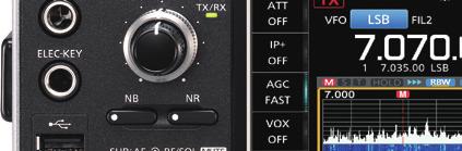
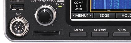
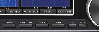
10 1 PANEL DESCRIPTION Front panel w e r t y u i q q POWER KEY POWER (p. 3-1) Turns the transceiver ON or OFF. w TRANSMIT KEY TRANSMIT (p. 3-9) Toggles between transmit and receive. e TIMER KEY TIMER Turns the Sleep Timer or Daily Timer function ON or OFF.!2 o!1!0 o The TX/RX indicator Lights green while receiving. Lights red while transmitting. r HEADPHONE JACK [PHONES] (p. 13-3) Connects to standard stereo headphones. t ELECTRONIC KEYER JACK [ELEC-KEY] (p. 13-3) Connects to a paddle to use the internal electronic keyer for the CW operations. y USB PORT [USB A] (p. 13-4) Insert a USB flash drive, USB A type keyboard, RC- 28 remote encoder, mouse or hub. u MICROPHONE CONNECTOR [MIC] (p. 13-3) Connects to the supplied or an optional microphone. i SD CARD SLOT [SD CARD] (p. 6-1) Accepts an SD card. The indicator next to the slot lights blue when inserted. o VOLUME CONTROL AF RF/SQL (p. 3-1) L The upper control is for the Main band, and the lower control is for the Sub band. Push to turn the Mute function ON or OFF. - The TX/RX indicator lights orange when turned ON. Adjusts the audio output level. RF GAIN/SQUELCH CONTROL AF RF/SQL (p. 3-7) Adjusts the RF gain and squelch threshold levels.!0 NOISE REDUCTION KEY NR (p. 6-5) Turns the Noise Reduction function ON or OFF.!1 NOISE BLANKER KEY NB (p. 6-5) Turns the Noise Blanker ON or OFF.!2 ANTENNA TUNER KEY TUNER (p. 7-3) Turns the antenna tuner ON or OFF, or activates MENU KEY MENU (p. 8-1) Displays the MENU screen.!4 MINI SCOPE KEY M.SCOPE (p. 5-2) Displays the Mini Scope or Spectrum Scope.!5 MEMO PAD WRITE KEY MP-W Saves the displayed contents into the Memo Pad.!6 MEMO PAD READ KEY MP-R Sequentially calls up the contents in the Memo Pad.!7 AUTO TUNE KEY AUTO TUNE (p. 4-8) Automatically tunes the operating frequency to a received CW signal.!8 QUICK KEY QUICK (p. 1-7) Displays the QUICK MENU. 1-1
11 PANEL DESCRIPTION 1 Front panel (Continued)!9 EXIT KEY EXIT Exits a setting screen or returns to the previous VOICE MEMORY RECORD KEY REC Saves the previously received signal for the preset time period set in REC Time, using the Instant Replay function, or starts recording a QSO audio onto an SD VOICE MEMORY PLAY BACK KEY PLAY Plays back the last 5 seconds of the Instant Replay memory, or all of the Instant @9 MULTI-FUNCTION CONTROL MULTI (p. 1-6) Displays the Multi-function menu for various adjustments, or selects an SPLIT KEY SPLIT (p. 4-9) Turns the Split function ON or DUALWATCH KEY DUAL-W (p. 3-2) Turns the Dualwatch function ON or GENERAL COVERAGE BAND KEY GENE Selects the general coverage band. #9 #8 #7 #6 #5 #4 #3 TRANSMIT FREQUENCY CHECK KEY XFC (p. 4-1, 4-9, 4-10) Enables you to monitor the transmit frequency while holding it down in the Split TENSION ADJUSTER Adjusts the friction of MAIN MAIN DIAL MAIN DIAL (p. 3-4) Changes the operating frequency. SPEECH/LOCK KEY SPEECH Announces the operating frequency and mode by pushing this key. Electronically locks MAIN DIAL by holding down this key for 1 second. #0 MAIN/SUB CHANGE KEY CHANGE (p. 3-2) Toggles the frequency, mode and selected memory channel between the Main and Sub band. #1 RIT/ TX CONTROL RIT/ TX (p. 4-1) Shifts the receive or transmit frequency up to ±9.99 khz without changing the transmit or receive frequency. #2 TX KEY TX Turns the TX function ON or OFF. #3 CLEAR KEY CLEAR Clears the RIT or TX shift frequency. #4 RIT KEY RIT (p. 4-1) Turns the Receiver Incremental Tuning (RIT) function ON or OFF. #5 KEY SPEED KEY SPEED PITCH CONTROL (p. 4-11) Adjusts the internal electronic CW keyer speed. CW PITCH KEY SPEED PITCH CONTROL (p. 4-10) Shifts the received CW audio pitch and the CW side tone pitch without changing the operating frequency. #6 MAIN/SUB ACCESS KEY MAIN/SUB (p. 3-2) Selects the Main or Sub band frequency readout. The selected band s frequency is displayed clearly whereas the non-selected band s frequency is displayed in gray. #7 AUDIO PEAK FILTER/ TWIN PEAK FILTER KEY APF/TPF (p. 4-12) In the CW mode, turns the Audio Peak Filter ON or OFF, and in the RTTY mode, turns the Twin Peak Filter ON or OFF. #8 FILTER KEY FILTER (p. 4-4) Selects one of three IF filters. #9 TWIN PASSBAND TUNING CONTROL TWIN PBT CLR (p. 4-3) Adjusts the IF filter s passband width. $0 KEYPAD 1.8 ~ 50 Selects the operating band by pushing once, or call up other stacked frequencies by pushing the same key several times
12 1 PANEL DESCRIPTION Rear panel q w e r t!5!5!6!7!8!9 y u!4!3!2!1!0 o i q DC POWER SOCKET [DC 13.8 V] Connects to 13.8 V DC through the DC power cable. w TUNER CONTROL SOCKET [TUNER] Accepts the control cable from an optional AH-4 or AH-740 automatic antenna tuner. e COOLING FAN Cools the PA unit when necessary. r GROUND TERMINAL [GND] Connects to ground to prevent electrical shocks, TVI, BCI and other problems. t ANTENNA CONNECTOR [ANT1]/[ANT2] Connects to a 50 Ω antenna. If you use the AH-4 or AH-740, you must connect the antenna to [ANT1]. y ALC INPUT JACK [ALC] Connects to the ALC output jack of a non-icom linear amplifier. u SEND CONTROL JACK [SEND] Connects to control transmit with non-icom external units. i EXTERNAL SPEAKER JACK A/B [EXT-SP] Accepts a 4 ~ 8 Ω external speaker. o USB PORT [USB 1] (Type B) Connects to a PC for remote control operations.!0 USB PORT [USB 2] (Type B) For digital data input or output.!1 EXTERNAL DISPLAY CONNECTOR [EXT-DISPLAY] Connects to an external display monitor.!2 ETHERNET CONNECTOR [LAN] Connects to a PC network through a LAN.!3 TRANSVERTER CONNECTOR [X-VERTER] Connects to an external transverter for input/output.!4 REFERENCE SIGNAL INPUT [REF IN] Input for a 10 MHz reference signal through the BNC connector.!5 RECEIVE ANTENA [RX ANT IN]/[RX ANT OUT] Connects to an external unit, such as preamplifier or RF filter, using BNC connectors. This is located between the transmit/receive switching circuit and receiver s RF stage.!6 CI-V REMOTE CONTROL JACK [REMOTE] Connects to a PC or other transceiver for remote control.!7 METER JACK [METER] Outputs received signal strength, transmit output power, VSWR, ALC, speech compression, Vd or Id levels for an external meter.!8 EXTERNAL KEYPAD JACK [EXT KEYPAD] (p. 13-4) Connects to an external keypad for direct voice memory, memory keyer, RTTY memory or PSK memory transmission.!9 STRAIGHT KEY JACK [KEY] Connects to a straight key, paddle, or an external electronic keyer with 6.35 mm (¼ in) stereo ACC SOCKET [ACC1]/[ACC2] Connects to devices to control an external unit or to control the transceiver. 1-3
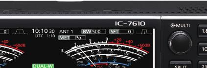
 Displays the selected antenna connector between ANT 1 and ANT 2. e METER TYPE INDICATOR (p. 3-7) Displays the selected transmit parameter type. Select between Po, SWR, ALC, COMP, Vd and Id.")
13 PANEL DESCRIPTION 1 Touch screen q w e r t y u i o!0!1 w e r t y u i q MULTI-FUNCTION KEY GROUP Displays the Multi-function keys. w ANTENNA INDICATOR (p. 7-1) Displays the selected antenna connector between ANT 1 and ANT 2. e METER TYPE INDICATOR (p. 3-7) Displays the selected transmit parameter type. Select between Po, SWR, ALC, COMP, Vd and Id. r BANDWIDTH INDICATOR (p. 4-3, 4-4) Displays the passband width of the IF filter. t SHIFT FREQUENCY INDICATOR (p. 4-3) Displays the shift frequency of the IF filter. y NOTCH INDICATOR (p. 4-6) AN is displayed when the Auto Notch function is ON, and MN is displayed when the Manual Notch function is ON. u PASSBAND WIDTH INDICATOR (p. 4-3) Displays the passband width for twin PBT operation and the center frequency for IF shift operation. i AUDIO PEAK FILTER (APF) INDICATOR (p. 4-12) Displayed when the Audio Peak Filter is ON. o CLOCK READOUT (p. 9-1) Displays the time (2 types) set on the TIME SET screen.!0 USB INDICATOR (p. 6-1) Displayed while a USB flashed drive is inserted.!1 LAN INDICATOR Displayed while the transceiver and the optional RS-BA1 are connected through the LAN for remote control operation. 1-4!2 BK-IN/F-BKIN INDICATOR (p. 4-11) Displayed while the Semi Break-in or Full Break-in function is ON.!3 NET FUNCTION INDICATOR (p. 8-7) Displayed when the NET function is ON while in the PSK mode.!4 FREQUENCY OFFSET READOUT Displays the offset value between the PSK signal and the operating frequency, while a PSK signal is received.!5 AFC FUNCTION INDICATOR Displayed while the Automatic Frequency Control (AFC) function is ON, in the PSK mode.!6 FREQUENCY READOUT (p. 3-4) Displays the operating frequency. L The non-selected band s frequency readout (Main or Sub) is displayed in gray.!7 FUNCTION DISPLAY Displayed when an item that has a function display is selected. For example, the Spectrum Scope.!8 FUNCTION KEYS (p. 5-1) Displays the operating parameters, modes, frequencies and indicators, and so on.!9 VOX INDICATOR Displayed while the VOX function is VOICE RECORDER ICON is displayed while recording. is displayed while pausing.!2!3!4!5!6!7!
 VFO is displayed when the VFO mode is selected, and the memory number is displayed when a Memory channel is selected. @2 TX STATUS INDICATOR (p.")
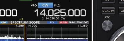
14 1 PANEL DESCRIPTION Touch screen @9 #0 #1 #2 @3 #9 #8 #7 #6 #5 $1 $0 #9 #8 #7 #6 VFO/MEMORY ICON (p. 3-1) VFO is displayed when the VFO mode is selected, and the memory number is displayed when a Memory channel is TX STATUS INDICATOR (p. 3-4, 3-9) Displays the transmit status of the displayed frequency. is displayed while the displayed frequency is within the amateur band range. (Red background) is displayed while transmitting. (With a border of short dashes) is displayed when the selected frequency is outside of the amateur band frequency. (Grayed out) is displayed while the transmitter is RF GAIN INDICATOR (p. 3-7) Displayed when AF RF/SQL (outer) is set counterclockwise from the 11 o clock position. The indicator shows that the RF gain is OVF ICON (p. 3-7) OVF is displayed when an excessively strong signal is METER INDICATOR (p. 3-7) Displays the S, Id, Po, SWR, COMP, ALC and Vd MODE INDICATOR (p. 3-3) Displays the selected operating IF FILTER INDICATOR (p. 4-3, 4-4) Displays the selected IF QUICK TUNING ICON (p. 3-4) Displayed when the quick Tuning Step function is AUTO TUNE INDICATOR (p. 4-8) Displays AUTOTUNE when the Auto Tuning function is ON. #0 SPLIT ICON (p. 4-9) Displayed when the Split function is ON. #1 DUALWATCH ICON (p. 3-2) Displayed when using Dualwatch. #2 SHIFT FREQUENCY READOUT (p. 4-1) Displays the shift offset for the RIT or TX functions, while these functions are ON. #3 RIT ICON (p. 4-1) Displayed when the RIT function is ON. #4 TX ICON Displayed when the TX function is ON. #5 1/4 TUNING STEP INDICATOR (p. 3-5) Displayed while the 1/4 Tuning Step function is ON. #6 M1~M8/T1~T8 Displays M1 ~ M8 while using the Memory Keyer function is used. Displays T1 ~ T8 while using the Voice TX memory function. #7 MEMORY CHANNEL/VFO READOUT (p. 3-1) Displays the selected memory channel contents in the VFO mode, and displays the VFO contents in the Memory mode. #8 LMT ICON Displayed if the power amplifier temperature becomes extremely high and the protection function is activated after transmitting continuously for long periods of time. #9 SELECT MEMORY CHANNEL ICON Indicates that the displayed memory channel is assigned as a Select memory channel ( 1~ 3). $0 PLAY ICON Displayed while playing the recorded voice audio. $1 DIAL LOCK INDICATOR (p. 3-6) Displayed while the Lock function is ON. 1-5


15 PANEL DESCRIPTION 1 Touch screen display (Continued) DDMENU screen DDMulti-function menus Touch to turn ON or OFF Multi-function menu zopen the Multi-function menu by pushing (Multi-function control). MULTI zwhile the Multi-function menu is open, touch the desired item and rotate MULTI to adjust the value. L You can open other menus by holding down NB or NR for 1 second, or touching ATT, VOX, BK-IN or COMP in the Multi-function key group for 1 second. zopen the MENU screen by pushing MENU. Function name Status Lights blue or orange when in use L The items displayed on the menu differ, depending on the selected operating mode. Multi-function menu items SSB CW RTTY PSK RF POWER RF POWER RF POWER RF POWER MIC GAIN DIGI-SEL DIGI-SEL DIGI-SEL DIGI-SEL NOTCH NOTCH NOTCH NOTCH NOTCH WIDTH NOTCH WIDTH NOTCH WIDTH NOTCH WIDTH MONITOR MONITOR MONITOR AM FM NB NR RF POWER RF POWER LEVEL LEVEL MIC GAIN MIC GAIN DEPTH DIGI-SEL DIGI-SEL WIDTH NOTCH NOTCH NOTCH WIDTH MONITOR MONITOR ATT VOX BK-IN COMP LEVEL GAIN DELAY LEVEL ANTI VOX TBW DELAY VOICE DELAY


16 1 PANEL DESCRIPTION Touch screen display (Continued) DDMulti-function key group Touch to turn ON or OFF, or to set Multi-function key group Multi-function key group items SSB CW RTTY PSK AM FM ANT P.AMP ATT IP+ AGC VOX BK-IN COMP TONE ztouch a key to turn the function ON or OFF. ztouching ATT, VOX, BK-IN or COMP for 1 second opens the ATT menu, VOX menu, BK-IN menu or COMP menu. L See Multi-function menus on the previous page for details. DDQUICK MENU zopen the QUICK MENU by pushing QUICK. 1-7

 ~ (T8) MEMORY NAME DDKeyboard types You can select the Full Keyboard or Tenkey by pushing QUICK")

17 PANEL DESCRIPTION 1 Keyboard entering and editing You can enter and edit the items on the following screens. LUsable characters, symbols, and the amount of characters that can be entered differs, depending on the editing item. MY CALL FILE NAME NETWORK NAME NETWORK RADIO NAME NETWORK USER1 ID NETWORK USER2 ID NETWORK USER 1 PASSWORD NETWORK USER 2 PASSWORD NTP SERVER ADDRESS CLOCK2 NAME KEYER MEMORY PSK MEMORY RTTY MEMORY VOICE TX RECORD (T1) ~ (T8) MEMORY NAME DDKeyboard types You can select the Full Keyboard or Tenkey by pushing QUICK while displaying an entry mode screen. DDEntering and editing Moves the cursor backward Enters an uppercase letter Moves the cursor forward Clears the entered character Selects the character type Saves the entry Selects alphabet mode or number mode Enters a space Cancels entry and returns to the previous screen Alphabet mode Number mode Symbol mode 1-8


![Touch [SPACE] to enter a space. 9. Touch [ab].](/docs-images/94/119905856/images/18-3.jpg "The CHARACTER TYPE screen is displayed. 3. Touch Edit Name.")

![10. Touch [12]. 4. Touch [ ], and then touch [D].](/docs-images/94/119905856/images/18-5.jpg "L Touching [ ] changes between uppercase and lowercase letter. 11.")
18 1 PANEL DESCRIPTION Keypad entering and editing (Continued) DDEntering and editing example Entering DX spot 1 in the Memory channel 2 1. Display the MEMORY screen. MENU» MEMORY 2. Touch the memory channel 2 for 1 second. The MEMORY MENU screen is displayed. 7. Touch [s], [p], [o], and then [t]. 8. Touch [SPACE] to enter a space. 9. Touch [ab]. The CHARACTER TYPE screen is displayed. 3. Touch Edit Name. The MEMORY NAME screen is displayed. You can also display the MEMORY MENU screen by touching this key. 10. Touch [12]. 4. Touch [ ], and then touch [D]. L Touching [ ] changes between uppercase and lowercase letter. 11. Touch [1]. 12. Touch [ENT] to save the entry. 5. Touch [ ] again, and then touch [X]. 6. Touch [SPACE] to enter a space. Returns to the previous screen. 1-9
FULL MANUAL. HF/50 MHz TRANSCEIVER i7300 INTRODUCTION 1 PANEL DESCRIPTION 2 INSTALLATION AND CONNECTIONS 3 BASIC OPERATION
 FULL MANUAL INTRODUCTION 1 PANEL DESCRIPTION 2 INSTALLATION AND CONNECTIONS 3 BASIC OPERATION HF/50 MHz TRANSCEIVER i7300 4 RECEIVING AND TRANSMITTING 5 SCOPE OPERATION 6 VOICE RECORDER FUNCTIONS 7 VOICE
LCD VALUE SERIES (32 inches)
") LCD VALUE SERIES (32 inches) http://www.orionimages.com All contents of this document may change without prior notice, and actual product appearance may differ from that depicted herein 1. SAFETY INSTRUCTION
LCD VALUE SERIES (32 inches) http://www.orionimages.com All contents of this document may change without prior notice, and actual product appearance may differ from that depicted herein 1. SAFETY INSTRUCTION
USER MANUAL. 27 Full HD Widescreen LED Monitor L27ADS
 USER MANUAL 27 Full HD Widescreen LED Monitor L27ADS TABLE OF CONTENTS 1 Getting Started 2 Control Panel/ Back Panel 3 On Screen Display 4 Technical Specs 5 Care & Maintenance 6 Troubleshooting 7 Safety
USER MANUAL. 22" Class Slim HD Widescreen Monitor L215DS
 USER MANUAL 22" Class Slim HD Widescreen Monitor L215DS TABLE OF CONTENTS 1 Getting Started Package Includes Installation 2 Control Panel / Back Panel Control Panel Back Panel 3 On Screen Display 4 Technical
TV Connector user guide
 TV Connector user guide Thank you Thank you for choosing the TV Connector. The intended use of the TV Connector is to connect your hearing aids directly to your TV or audio source. Your TV Connector Hearing
USER MANUAL. 27 Full HD Widescreen LED Monitor L270E
 USER MANUAL 27 Full HD Widescreen LED Monitor L270E TABLE OF CONTENTS 1 Getting Started 2 Control Panel/ Back Panel 3 On Screen Display 4 Technical Specs 5 Care & Maintenance 6 Troubleshooting 7 Safety
USER MANUAL Full HD Widescreen LED Monitor L215IPS
 USER MANUAL 21.5 Full HD Widescreen LED Monitor L215IPS TABLE OF CONTENTS 1 Getting Started 2 Control Panel/ Back Panel 3 On Screen Display 4 Technical Specs 5 Care & Maintenance 6 Troubleshooting 7 Safety
User Manual MODEL: KK1500-TR. Touch Display LCD Monitor. Installation Guide. 15 Resistive Touch LCD Monitor
 Touch Display LCD Monitor User Manual Installation Guide 15 Resistive Touch LCD Monitor MODEL: KK1500-TR i-tech Company LLC TOLL FREE: (888) 483-2418 EMAIL: info@itechlcd.com WEB: www.itechlcd.com User
USER MANUAL. 28" 4K Ultra HD Monitor L28TN4K
 USER MANUAL 28" 4K Ultra HD Monitor L28TN4K TABLE OF CONTENTS 1 Getting Started 2 Control Panel/ Back Panel 3 On Screen Display 4 Technical Specs 5 Care & Maintenance 6 Troubleshooting 7 Safety Info &
USER MANUAL Full HD Widescreen LED Monitor L215ADS
 USER MANUAL 21.5 Full HD Widescreen LED Monitor L215ADS TABLE OF CONTENTS 1 Getting Started 2 Control Panel/ Back Panel 3 On Screen Display 4 Technical Specs 5 Care & Maintenance 6 Troubleshooting 7 Safety
User Manual MODEL: KKF1500-PCAP. True FLAT P-CAP LCD Monitor. Installation Guide. 15 True FLAT P-CAP Touch LCD Monitor
 True FLAT P-CAP LCD Monitor User Manual Installation Guide 15 True FLAT P-CAP Touch LCD Monitor MODEL: KKF1500-PCAP i-tech Company LLC TOLL FREE: (888) 483-2418 EMAIL: info@itechlcd.com WEB: www.itechlcd.com
17" & 19" Color TFT LCD Monitor
 17" & 19" Color TFT LCD Monitor KMC-17B & KMC-19B User's Manual for Operation and installation Screen Size : KMC-17B (17" inch TFT LCD) KMC-19B (19" inch TFT LCD) Display Size : KMC-17B (337.920mm X 270.336mm)
CAUTION RISK OF ELECTRIC SHOCK NO NOT OPEN
 Evolution Digital HD Set-Top Box Important Safety Instructions 1. Read these instructions. 2. Keep these instructions. 3. Heed all warnings. 4. Follow all instructions. 5. Do not use this apparatus near
LINK-MI LM-WHD05B. Wireless HDMI AV Transmission System. User Manual
 LINK-MI LM-WHD05B Wireless HDMI AV Transmission System User Manual Table of Contents 1.Important Information... 3 1.1 Safety Precautions... 3 1.2 Declaration of Conformity... 4 1.3 Trademark Information...
TV Connector user guide
 TV Connector user guide Thank you Thank you for choosing the TV Connector. The intended use of the TV Connector is to connect your hearing aids directly to your TV or audio source. Your TV Connector Hearing
AUTO - SCANNING WITH DIGITAL CONTROL LCD COLOR MONITOR FS-L1903C. User manual (Rev.01) SMITHS HEIMANN
 SMITHS HEIMANN") AUTO - SCANNING WITH DIGITAL CONTROL LCD COLOR MONITOR FS-L1903C User manual (Rev.01) SMITHS HEIMANN www.smithsdetection.com Table of Contents Safety Instructions... 5 Accessories... 8 Power Connections...
AUTO - SCANNING WITH DIGITAL CONTROL LCD COLOR MONITOR FS-L1903C User manual (Rev.01) SMITHS HEIMANN www.smithsdetection.com Table of Contents Safety Instructions... 5 Accessories... 8 Power Connections...
DDW36C Advanced Wireless Gateway - Safety and Installation Product Insert. Federal Communications Commission (FCC) Interference Statement
 Interference Statement") DDW36C Advanced Wireless Gateway - Safety and Installation Product Insert Federal Communications Commission (FCC) Interference Statement This equipment has been tested and found to comply with the limits
DDW36C Advanced Wireless Gateway - Safety and Installation Product Insert Federal Communications Commission (FCC) Interference Statement This equipment has been tested and found to comply with the limits
DCL9AW. User Manual. English
 DCL9AW User Manual English PRECAUTIONS Information for users applicable in European Union countries 1 Information for users applicable in United States of America 1 Installation 1 Power connection 1 Maintenance
HD Digital MPEG2 Encoder / QAM Modulator
 HD Digital MPEG2 Encoder / QAM Modulator HDMI In QAM Out series Get Going Guide ZvPro 800 Series is a one or two-channel unencrypted HDMI-to-QAM MPEG 2 Encoder / QAM Modulator, all in a compact package
LCD MONITOR. 27 Wide LED Monitor User Manual. User Manual P276L
 LCD MONITOR 27 Wide LED Monitor User Manual User Manual P276L Precautions Precautions Warning The following information will help you avoid the risk of electric shock, serious injury or death. Power cord
600 Series Video Surveillance Monitors
 600 Series Video Surveillance Monitors 32 LED Monitor 43, 50, 55 & 55 4K LED Monitor Models: PMCL632: PMCL643 PMCL650 PMCL655 PMCL655K Contents for Wall Mount Monitor User Manual (10/16)... 1 Important
HD Digital MPEG2 Encoder / QAM Modulator Get Going Guide
 series HD Digital MPEG2 Encoder / QAM Modulator Get Going Guide HDb2640 HDb2620 HDb2540 HDb2520 The HDbridge 2000 Series is a combination HD MPEG 2 Encoder and frequency-agile QAM Modulator, all in a 1RU
PL2410W LCD Monitor USER'S GUIDE.
 PL2410W LCD Monitor USER'S GUIDE www.planar.com Content Operation Instructions...1 Safety Precautions...2 First Setup...3 Front View of the Product...4 Rear View of the Product...5 Quick Installation...6
USER MANUAL Full HD Widescreen LED Monitor L236VA
 USER MANUAL 23.6 Full HD Widescreen LED Monitor L236VA TABLE OF CONTENTS 1 Getting Started 2 Control Panel/ Back Panel 3 On Screen Display 4 Technical Specs 5 Care & Maintenance 6 Troubleshooting 7 Safety
It will cause malfunction if the monitor is operating with unspecified power supply
 User Manual / Installation Guide Model No. PTM-1525R/RT Warning! It will cause malfunction if the monitor is operating with unspecified power supply unit or incorrect power voltage. Do not exposure this
VNS2200 Amplifier & Controller Installation Guide
 VNS2200 Amplifier & Controller Installation Guide VNS2200 Amplifier & Controller Installation 1. Determine the installation location for the VNS2200 device. Consider the following when determining the
HD Digital Set-Top Box Quick Start Guide
 HD Digital Set-Top Box Quick Start Guide Eagle Communications HD Digital Set-Top Box Important Safety Instructions WARNING TO REDUCE THE RISK OF FIRE OR ELECTRIC SHOCK, DO NOT EXPOSE THIS PRODUCT TO RAIN
ES-3305P / ES-3308P / ES-3316P. Quick Installation Guide / v1.0
 ES-3305P / ES-3308P / ES-3316P Quick Installation Guide 09-2012 / v1.0 1 COPYRIGHT Copyright Edimax Technology Co., Ltd. all rights reserved. No part of this publication may be reproduced, transmitted,
HD Digital MPEG2 Encoder / QAM Modulator
 HD Digital MPEG2 Encoder / QAM Modulator YPrPb VGA In QAM Out series Get Going Guide ZvPro 600 Series is a one or two-channel Component or VGA-to-QAM MPEG 2 Encoder/ Modulator, all in a compact package
PLL2210MW LED Monitor
 PLL2210MW LED Monitor USER'S GUIDE www.planar.com Content Operation Instructions...1 Safety Precautions...2 First Setup...3 Front View of the Product...4 Rear View of the Product...5 Quick Installation...6
MONOPRICE. BitPath AV SDI Extender over Single Cat6 Cable, 120m. User's Manual P/N 16227
 MONOPRICE BitPath AV SDI Extender over Single Cat6 Cable, 120m P/N 16227 User's Manual SAFETY WARNINGS AND GUIDELINES Please read this entire manual before using this device, paying extra attention to
2.0 Wall Mount TV Soundbar Instruction Manual
 8010275 2.0 Wall Mount TV Soundbar Instruction Manual Read all of the instructions before using this soundbar and keep the manual in a safe place for future reference. Safety Information CA UT IO N RISK
2.4 GHz WIRELESS SURVEILLANCE SYSTEM
 2.4 GHz WIRELESS SURVEILLANCE SYSTEM Operating Instructions Tested Comply With FCC Standards Model # TBM-18 BEFORE OPERATING THIS PRODUCT, READ, UNDERSTAND, AND FOLLOW THESE INSTRUCTIONS. Be sure to save
TFT LCD MONITOR USER MANUAL. L80AP and L101AP
 TFT LCD MONITOR USER MANUAL L80AP - 8.0 and L101AP - 10.1 Table Of Contents Table of contents/ Warning.... 2 Precautions...3 About this user manual and products / Items included in the delivery..... 4
User's Manual HDMI 4K*2K 3D Splitter 1x2
 User's Manual HDMI 4K*2K 3D Splitter 1x2 Product numbers: KN40592 Thank you for purchasing the HDMI splitter from KanaaN. We hold several brands to produce and distribute our products: LEICKE (power adapters,
MONOPRICE. BitPath AV HDMI Extender over Single Cat6 Cable, 120m. User's Manual P/N 16228
 MONOPRICE BitPath AV HDMI Extender over Single Cat6 Cable, 120m P/N 16228 User's Manual SAFETY WARNINGS AND GUIDELINES Please read this entire manual before using this device, paying extra attention to
P-2 Installing the monitor (continued) Carry out as necessary
 Carry out as necessary") P-2 Installing the monitor (continued) Carry out as necessary Using the monitor without the bezel MDT552S satisfies the UL requirements as long as it is used with the bezel attached. When using the monitor
P-2 Installing the monitor (continued) Carry out as necessary Using the monitor without the bezel MDT552S satisfies the UL requirements as long as it is used with the bezel attached. When using the monitor
DISTRIBUTION AMPLIFIER
 MANUAL PART NUMBER: 400-0045-005 DA1907SX 1-IN, 2-OUT VGA/SVGA/XGA/UXGA DISTRIBUTION AMPLIFIER USER S GUIDE TABLE OF CONTENTS Page PRECAUTIONS / SAFETY WARNINGS... 2 GENERAL...2 GUIDELINES FOR RACK-MOUNTING...2
Evolution Digital HD Set-Top Box Important Safety Instructions
 Evolution Digital HD Set-Top Box Important Safety Instructions 1. Read these instructions. 2. Keep these instructions. 3. Heed all warnings. 4. Follow all instructions. 5. Do not use this apparatus near
IPSTB1200 /IPC3200 Media Client User guide
 IPSTB1200 /IPC3200 Media Client User guide Safety/Compliance Important Safety Instructions Please carefully read these safety and compliance instructions and this entire user guide. Follow all instructions
MONOPRICE. BitPath AV VGA Extender over Single Cat6 Cable, 120m. User's Manual P/N 16226
 MONOPRICE BitPath AV VGA Extender over Single Cat6 Cable, 120m P/N 16226 User's Manual SAFETY WARNINGS AND GUIDELINES Please read this entire manual before using this device, paying extra attention to
4 PORT HDMI SWITCH
 4 PORT HDMI SWITCH 1518896 IMPORTANT SAFEGUARDS OF HDMI SWITCH PRODUCTS PLEASE READ CAREFULLY THE FOLLOWING SAFEGUARDS THAT ARE APPLICABLE TO YOUR EQUIPMENT 1. Read instructions - All the safety and operating
OPERATING INSTRUCTIONS TOM-0431IP
 OPERATING INSTRUCTIONS TOM-0431IP Table of Contents FCC Information -------------------------------------------------------------------- 2 Safety and Environmental Precautions ------------------------------------------------
MONOPRICE. BitPath AV 4K 1X4 HDMI Splitter Extender over Single Cat6 with IR, 120m. User's Manual P/N 16286
 MONOPRICE BitPath AV 4K 1X4 HDMI Splitter Extender over Single Cat6 with IR, 120m P/N 16286 User's Manual SAFETY WARNINGS AND GUIDELINES Please read this entire manual before using this device, paying
17 19 PROFESSIONAL LCD COLOUR MONITOR ART
 17 19 PROFESSIONAL LCD COLOUR MONITOR ART. 41657-41659 Via Don Arrigoni, 5 24020 Rovetta S. Lorenzo (Bergamo) http://www.comelit.eu e-mail:export.department@comelit.it WARNING: TO REDUCE THE RISK OF FIRE
TV Adapter 2 INSTALLATION GUIDE INSTRUCTIONS FOR USE
 TV Adapter 2 INSTALLATION GUIDE INSTRUCTIONS FOR USE 2 Table of Contents General Warnings 6 Introduction 8 TV Adapter 2 Overview 9 Installation 11 Activating the TV Adapter 2 for the First Time 12 Connecting
PLL1920M LED LCD Monitor
 PLL1920M LED LCD Monitor USER'S GUIDE www.planar.com Content Operation Instructions...1 Safety Precautions...2 First Setup...3 Front View of the Product...4 Rear View of the Product...5 Installation...6
MONOPRICE. Blackbird 4K HDBaseT Extender Kit. User's Manual P/N 21792
 MONOPRICE Blackbird 4K HDBaseT Extender Kit P/N 21792 User's Manual SAFETY WARNINGS AND GUIDELINES Please read this entire manual before using this device, paying extra attention to these safety warnings
Camera 220C Document Camera User s Guide
 Camera 220C Document Camera User s Guide #401-220C-00 Table of Contents TABLE OF CONTENTS... 0 TABLE OF CONTENTS... 1 COPYRIGHT INFORMATION... 2 CHAPTER 1 PRECAUTIONS... 3 CHAPTER 2 PACKAGE CONTENT...
OPERATIONS MANUAL FOR EDISON PROFESSIONAL Professional ABS Molded Loudspeaker M4000
 M4000 Introduction: Congratulations on your purchase of an M-4000 powered loudspeaker, engineered and manufactured by BriteLite Enterprises. The M-4000 includes a high-output compression driver, and 15
Register your product and get support at SDV5122/27. EN User manual
 Register your product and get support at www.philips.com/welcome SDV5122/27 User manual Contents 1 Important 4 Safety 4 Notice for USA 5 Notice for Canada 5 Recycling 6 English 2 Your SDV5122 7 Overview
Wireless 5.8GHz AV Sender With Built in Remote Control Extender
 Wireless 5.8GHz AV Sender With Built in Remote Control Extender AR-1913 User Manual TABLE OF CONTENTS Box Contents..................2 User Guide.............3 Installation............4 Trouble Shooting............
INFORMATION TO THE USER
 U.S.FEDERAL COMMUNICATIONS COMMISSION RADIO FREQUENCY INTERFERENCE STATEMENT INFORMATION TO THE USER NOTE: This equipment has been tested and found to comply with the limits for a Class B digital device
 Register your product and get support at www.philips.com/welcome SWS3435S/27 SWS3435H/37 EN User manual Contents 1 Important 4 Safety 4 English 2 Your SWS3435 6 Overview 6 3 Installation 7 Connect the
22" Touchscreen LED Monitor USER'S GUIDE
 22" Touchscreen LED Monitor USER'S GUIDE Content Operation Instructions...1 Unpacking Instructions...2 Safety Precautions...2 Front View of the Product...3 Rear View of the Product...4 Quick Installation...5
PXL2760MW LED LCD Monitor
 PXL2760MW LED LCD Monitor USER'S GUIDE www.planar.com Content Operation Instructions...1 Safety Precautions...2 Package Overview...3 First Setup...4 Front View of the Product...5 Rear View of the Product...6
Operating Instructions
 Operating Instructions SDI Input board Model No. AV-HS04M1 РУССКИЙ FRANÇAIS DEUTSCH ENGLISH ESPAÑOL ITALIANO Before operating this product, please read the instructions carefully and save this manual for
ACCESSORIES MANUAL PART NUMBER: PRODUCT REVISION: 1 PNP202. Interconnect Box USER'S GUIDE
 MANUAL PART NUMBER: 400-0109-001 PRODUCT REVISION: 1 PNP202 Interconnect Box USER'S GUIDE INTRODUCTION Your purchase of the PNP202 Interconnect Box is greatly appreciated. We are sure you will find it
1-In / 2-Out. HDMI Splitter User s Guide
 1-In / 2-Out HDMI Splitter 1500659 User s Guide We hope you enjoy your 1-In / 2-Out HDMI Splitter from RadioShack. This HDMI splitter allows the 4K2K digital signal from a HDMI device to be displayed on
CU103 User Manual. Contents
 [Note] The Photos of Light Engine and Control Unit in this manual are for reference only. The items may be different in actual package. Contents 1. PRECAUTIONS... 2 2. PACKAGE CONTENT... 4 3. PORT DESCRIPTION...
Warning...1 Safety Precaution...3
 PL1910W Contents Preface...1 Warning...1 Safety Precaution......3 Installation...4 Introduction...4 Features...4 Unpacking...5 Attaching the Base...6 Removing the Base...7 Preparing The Monitor For Wall-Mounting...8
2nd Edition. Quick Start Guide. getawair.com
 2nd Edition Quick Start Guide getawair.com Stay Healthy Awair tracks toxins and chemicals in your air and gives you personalized recommendations to help you stay safe and healthy. Sensors Fine Dust (PM2.5)
Welcome to NEED HELP? DIRECTV offers the best entertainment experience. Use this guide to make the most of it LKR FCC ID : ORS
 NEED HELP? Important Tips Do not unplug your receiver If you unplug it you may miss the most recent updates that improve our service. The DIRECTV receiver is designed to consume very little energy while
User Manual MODEL: KKW700V. Non-Touch True Display LCD Monitor. Installation Guide. 7 True Display LCD Monitor (VGA Interface)
") Non-Touch True Display LCD Monitor User Manual Installation Guide 7 True Display LCD Monitor (VGA Interface) MODEL: KKW700V i-tech Company LLC TOLL FREE: (888) 483-2418 EMAIL: info@itechlcd.com WEB: www.itechlcd.com
Non-Touch True Display LCD Monitor User Manual Installation Guide 7 True Display LCD Monitor (VGA Interface) MODEL: KKW700V i-tech Company LLC TOLL FREE: (888) 483-2418 EMAIL: info@itechlcd.com WEB: www.itechlcd.com
MONOPRICE. 27" UHD IPS 4K Ultra Slim Aluminum Monitor. Quick User's Guide P/N 24658
 MONOPRICE 27" UHD IPS 4K Ultra Slim Aluminum Monitor P/N 24658 Quick User's Guide SAFETY WARNINGS AND GUIDELINES Please read this entire manual before using this device, paying extra attention to these
Hardware User s Manual
 Hardware User s Manual Megapixel Day & Night Economy Bullet Network Camera English 1 Table of Contents Before You Use This Product... 2 Regulatory Information... 3 Chapter 1 - Package Contents... 4 Chapter
USER MANUAL. 27" 2K QHD LED Monitor L27HAS2K
 USER MANUAL 27" 2K QHD LED Monitor L27HAS2K TABLE OF CONTENTS 1 Getting Started 2 Control Panel/ Back Panel 3 On Screen Display 4 Technical Specs 5 Troubleshooting 6 Safety Info & FCC warning 1 GETTING
MONOPRICE. BitPath AV 4K HDMI Wireless Transmitter & Receiver Kit, 200m. User's Manual P/N 16223
 MONOPRICE BitPath AV 4K HDMI Wireless Transmitter & Receiver Kit, 200m P/N 16223 User's Manual SAFETY WARNINGS AND GUIDELINES Please read this entire manual before using this device, paying extra attention
27'' Full HD LED Monitor KALED27MONSC Quick Start Guide
 Safety Warnings 27'' Full HD LED Monitor KALED27MONSC Quick Start Guide TO REDUCE THE RISK OF ELECTRIC SHOCK, DO NOT REMOVE ANY COVERS (OR BACKINGS). NO USER SERVICEABLE PARTS ARE INSIDE. REFER ALL SERVICING
Picture Fan. display your photos, graphics & messages
 Picture Fan display your photos, graphics & messages Table of contents Warnings and Cautions....1 FCC Information...5 Location of Parts and Controls....6 Home Screen App Control...7 Picture Fan Operation....8
Check our knowledge base at
 USER MANUAL Check our knowledge base at www.paralinx.net/support Copyright 2015 Paralinx LLC All Rights Reserved TABLE OF CONTENTS 1 Important Notice 10 LCD Screen 2 Safety Instructions 11 Indicators 3
ACCESSORIES MANUAL PART NUMBER: PRODUCT REVISION: 1 TNP100. Tilt N Plug Interconnect Box USER'S GUIDE
 MANUAL PART NUMBER: 400-0091-001 PRODUCT REVISION: 1 TNP100 Tilt N Plug Interconnect Box USER'S GUIDE INTRODUCTION Your purchase of the TNP100 Tilt N Plug Interconnect Box is greatly appreciated. We are
MONOPRICE. Blackbird 4K HDMI Extender. User's Manual P/N 24281
 MONOPRICE Blackbird 4K HDMI Extender P/N 24281 User's Manual SAFETY WARNINGS AND GUIDELINES Please read this entire manual before using this device, paying extra attention to these safety warnings and
FD Trinitron Colour Television
 R 4-205-569-32(1) FD Trinitron Television Instruction Manual GB KV-14LM1U 2000 by Sony Corporation NOTICE FOR CUSTOMERS IN THE UNITED KINGDOM A moulded plug complying with BS1363 is fitted to this equipment
MONOPRICE. BitPath AV SDI Wireless Transmitter & Receiver Kit, 200m. User's Manual P/N 16225
 MONOPRICE BitPath AV SDI Wireless Transmitter & Receiver Kit, 200m P/N 16225 User's Manual SAFETY WARNINGS AND GUIDELINES Please read this entire manual before using this device, paying extra attention
SAFETY WARNINGS AND GUIDELINES
 SAFETY WARNINGS AND GUIDELINES Please read this manual thoroughly, paying extra attention to these safety warnings and guidelines: Do not expose this monitor to water or moisture of any kind. Do not handle
User s Manual. Welcome. About the product. Safety Notice
 Welcome Thank you for purchasing this product. Please read this manual thoroughly before use and retain it for future reference. We are confident you will enjoy this product and its many functions. About
By CHANNEL VISION. Flush Mount Amplifier A0350
 Spkrs Local In IR In 24VDC A0350 10 The A0350 can be used with Channel Vision s CAT5 audio hubs to provide a powerful 50Watts per channel in the listening zone. Alternatively, the A0350 can be added to
MONOPRICE. BitPath AV VGA Wireless Transmitter & Receiver Kit, 200m. User's Manual P/N 16224
 MONOPRICE BitPath AV VGA Wireless Transmitter & Receiver Kit, 200m P/N 16224 User's Manual SAFETY WARNINGS AND GUIDELINES Please read this entire manual before using this device, paying extra attention
USER S MANUAL CCTV LED MONITOR MODEL: ADE-117N1 ADE-119N1 ADE-118W1 ADE-121W1 ADE-124W Atherton Electronics Corp. All rights reserved.
 USER S MANUAL CCTV LED MONITOR MODEL: ADE-117N1 ADE-119N1 ADE-118W1 ADE-121W1 ADE-124W1 2015 Atherton Electronics Corp. All rights reserved. TABLE OF CONTENTS FCC information -------------------------------------------------------------------
ES-5500M V2 / ES-5800M V2
 ES-5500M V2 / ES-5800M V2 Quick Installation Guide 05-2012 / v1.0 COPYRIGHT Copyright Edimax Technology Co., Ltd. all rights reserved. No part of this publication may be reproduced, transmitted, transcribed,
INSTALLATION GUIDE ConnectLine TV adapter Getting started
 INSTALLATION GUIDE ConnectLine TV adapter Getting started PURPOSE OF THIS GUIDE READ THIS FIRST Before your hearing instruments can receive the TV sound, the adapter must be connected to the TV and a power
19 / 20.1 / 22 WIDE SCREEN TFT-LCD MONITOR
 19 / 20.1 / 22 WIDE SCREEN TFT-LCD MONITOR V193/ V220 Series V202 Series USER MANUAL www.viewera.com Rev. 2.0 Table of Contents EMC Compliance......1 Important Precautions...2 1. Package contents....3
MONOPRICE. Blackbird 4K Pro HDBaseT Extender Kit. User's Manual P/N 21609
 MONOPRICE Blackbird 4K Pro HDBaseT Extender Kit P/N 21609 User's Manual SAFETY WARNINGS AND GUIDELINES Please read this entire manual before using this device, paying extra attention to these safety warnings
 Register your product and get support at www.philips.com/welcome SWW1890 User manual Contents 1 Important 4 Safety 4 English 2 Your Philips Wireless HD Net Connect 5 What is in the box 5 3 Overview 6
PXL2470MW LED LCD Monitor
 PXL2470MW LED LCD Monitor USER'S GUIDE www.planar.com Content Operation Instructions...1 Unpacking Instructions...2 Safety Precautions...2 Package Overview...3 First Setup...4 Front View of the Product...5
VLHDMIEXTFIB_2017V1.0
 User Manual VLHDMIEXTFI ll Rights Reserved Version: VLHDMIEXTFI_2017V1.0 Preface Read this user manual carefully before using the product. Pictures are shown in this manual for reference only, different
OWNER S MANUAL MOTORIZED 7 WIDE TFT LCD COLOR MONITOR CNT-701
 OWNER S MANUAL PW MOTORIZED 7 WIDE TFT LCD COLOR MONITOR CNT-701 ANY CHANGES OR MODIFICATIONS IN CONSTRUCTION OF THIS UNIT DEVICE WHICH IS NOT APPROVED BY THE PARTY RESPONSIBLE FOR COMPLIACE COULD VOID
PREMIUM WIDE ASPECT RATIO LED SERIES (18~23 inches)
") PREMIUM WIDE ASPECT RATIO LED SERIES (18~23 inches) http://www.orionimages.com All contents of this document may change without prior notice, and actual product appearance may differ from that depicted
PREMIUM WIDE ASPECT RATIO LED SERIES (18~23 inches) http://www.orionimages.com All contents of this document may change without prior notice, and actual product appearance may differ from that depicted
User Manual PS-684. HDBaseT Extender Kit 70m. All Rights Reserved. Version: UHBT70P_2016V1.2
 User Manual PS-684 All Rights Reserved Version: UHBT70P_2016V1.2 Preface Read this user manual carefully before using this product. Pictures shown in this manual is for reference only, different model
THD601DC Set-top box
 THD601DC Set-top box Contents 1. Safety... 1 2. Appearance... 2 3. Rear Panel Connection... 3 4. Remote... 4 5 First Time Set-Up... 7 6. Network Settings... 8 6.1 Available Networks and Checking Current
User Guide. Interton TV Streamer
 User Guide Interton TV Streamer Welcome Congratulations on your purchase of a Interton TV Streamer. Interton TV Streamer will provide you with high quality streamed audio from your TV, HiFi stereo, personal
DV6819 Quick Reference Guide V1.0. Smart TV Box. Quick Reference Guide. Please do read user manual before you operate the TV box.
 DV6819 Quick Reference Guide V1.0 Smart TV Box Quick Reference Guide Please do read user manual before you operate the TV box. ~ 1 ~ DV6819 Quick Reference Guide V1.0 Safety instruction Please keep the
 Register your product and get support at www.philips.com/welcome SDV5222T/27 User manual Contents 1 Important 4 Safety 4 Notice for USA 4 Notice for Canada 5 Recycling 5 English 2 Your SDV5222T 6 Overview
2. only. INTRODUCTION...3. Do SPECIFICATION...3 SYSTEM SETTINGS...7. Installation. Troubleshooting. OVERVIEW Important Information
 www.switronix.com Troubleshooting Installation Important Information Read Step1: REC this user s REC X5TX manual X5TX carefully before transmitter: use. It contains important information notes regarding
ZXV10 B760H ZXV10 B760E RichMedia Box User Guide
 ZTE CORPORATION NO.55,Hi-techRoadSouth,ShenZhen,P.R.China Postcode:518057 Tel: (86) 755 26771900 800-9830-9830 Fax: (86) 755 26772236 URL: http://support.zte.com.cn E-mail: doc@zte.com.cn ZXV10 B760H ZXV10
Reflecta Super 8 Scanner. User Manual
 Reflecta Super 8 Scanner User Manual 1 FEDERAL COMMUNICATIONS COMMISSION (FCC) STATEMENT This Equipment has been tested and found to comply with the limits for a class B digital device, pursuant to Part
ZvBox 150. HD video distribution over COAX Get Going Guide
 ZvBox 150 HD video distribution over COAX Get Going Guide ZvBox 150 is an HD MPEG 2 Encoder and frequency agile QAM Modulator. It allows you to convert any HD video source, Component or RGB (VGA), in real
PLL2710W LED LCD Monitor
 PLL2710W LED LCD Monitor USER'S GUIDE www.planar.com Content Operation Instructions...1 Safety Precautions...2 Package Overview...3 First Setup...4 Front View of the Product...5 Rear View of the Product...6
ir3 INSTRUCTION MANUAL COMMUNICATIONS RECEIVER
 INSTRUCTION MANUAL COMMUNICATIONS RECEIVER ir3 This device complies with Part 15 of the FCC rules. Operation is subject to the following two conditions: (1) This device may not cause harmful interference,