IMPORTANT SAFETY INSTRUCTIONS THESE INSTRUCTIONS ARE TO PROTECT YOU AND THE MCINTOSH INSTRUMENT. BE SURE TO FAMILIARIZE YOURSELF WITH THEM.
|
|
|
- Mabel Brooks
- 5 years ago
- Views:
Transcription
1
2 IMPORTANT SAFETY INSTRUCTIONS THESE INSTRUCTIONS ARE TO PROTECT YOU AND THE MCINTOSH INSTRUMENT. BE SURE TO FAMILIARIZE YOURSELF WITH THEM. 1. Read all instructions - Read the safety and operating instructions before operating the instrument. 2. Retain Instructions - Retain the safety and operating instructions for future reference. 3. Heed warnings - Adhere to warnings and operating instructions. 4. Follow Instructions - Follow all operating and use instructions. WARNING: TO REDUCE RISK OF FIRE OR ELECTRICAL SHOCK, DO NOT EXPOSE THIS INSTRUMENT TO RAIN OR MOISTURE. 5. Power Sources - Connect the power supply only to the type described in the operating instructions or as marked on the unit. 6. Power-Cord Protection - Route power-supply cords so that they are not likely to be walked on or pinched by items placed upon or against them, paying particular attention to cords at plugs, convenience receptacles, and the point where they exit from the instrument. 7. Ventilation - Locate the instrument for proper ventilation. For example, the instrument should not be placed on a bed, sofa, rug, or similar surface that may block ventilation openings; or, placed in a built-in installation, such as a bookcase or cabinet, that may impede the flow of air through the ventilation openings. 8. Heat - Locate the instrument away from heat sources such as radiators, heat registers, stoves, or other appliance (including amplifiers) that produce heat. 9. Wall or Cabinet Mounting - Mount the instrument in a wall or cabinet only as described in the owners manual. 10. Water and Moisture - Do not use the instrument near water - for example, near a bathtub, washbowl, kitchen sink, laundry tub, in a wet basement, or near a swimming pool, etc. 11. Cleaning - Clean the instrument by dusting with a dry cloth. Clean the panel with a cloth moistened with a window cleaner. 12. Object and Liquid Entry - Do not permit objects to fall and liquids to spill into the instrument through enclosure openings. SERVICE ENTRANCE EQUIPMENT POWER SERVICE GROUNDING ELECTRODE SYSTEM (reg. internal metal water pipe) BONDING JUMPER OPTIONAL ANTENNA GROUNDING ELECTRODE DRIVEN 8 FEET(2.44m) INTO THE EARTH IF REQUIRED BY LOCAL CODES SEE NEC SECTION STAND-OFF INSULATORS ANTENNA LEAD IN WIRE TO EXTERNAL ANTENNA TERMINALS OF PRODUCT 13. Power Lines - Locate any outdoor antenna away from power lines. 14. Outdoor Antenna Grounding - If an outdoor antenna is connected to the antenna terminal, be sure the antenna system is grounded to provide some protection against voltage surges and built up static charge. In the U.S.A., section 810 of the National Electrical Code, ANSl/NFPA No , provides information on the proper ground for the mast and supporting structure, ground for the lead-in wire to an antenna discharge unit, and size of ground conductors, location of antenna-discharge unit, connection to grounding electrodes, and requirements for the grounding electrode. For ground wire: a) Use No. 10 AWG (5.3 mm 2 ) copper No. 8 AWG (8.4 mm 2 ) aluminum, No. 17 AWG (1.0 mm 2 ) copper-clad steel, bronze wire, or larger as ground wire. b) Secure antenna lead-in and ground wires to house with stand-off insulators spaced from 4 feet (1.22 meters) to 6 feet (1.83 meters) apart. c) Mount antenna discharge unit as closely as possible to where lead-in enters house. d) Use jumper wire not smaller than No. 6 AWG (13.3 mm 2 ) copper or equivalent when separate antenna grounding electrode is used.
3 15. Nonuse Periods - Unplug the power cord from the AC power outlet when left unused for a long period of time. 16. Damage Requiring Service - Service must be performed by qualified service personnel when: A. The power supply cord or the plug has been damaged; or B. Objects have fallen, or liquid has been spilled into the instrument; or C. The instrument has been exposed to rain; or D. The instrument does not appear to operate normally or exhibits a marked change in performance; or E. The instrument has been dropped, or the enclosure damaged. 17. Servicing - Do not attempt to service beyond that described in the operating instructions. All other service should be referred to qualified service personnel. 18. Grounding or Polarization - Do not defeat the inherent design features of the polarized plug. Non-polarized line cord adaptors will defeat the safety provided by the polarized AC plug. 19. CAUTION: TO PREVENT ELECTICAL SHOCK DO NOT USE THIS (POLARIZED) PLUG WITH AN EXTENSION CORD, RECEPTACLE OR OTHER OUTLET UNLESS THE BLADES CAN BE FULLY INSERTED TO PREVENT BLADE EXPOSURE. Note to CATV system installer: This reminder is provided to call the CATV system installer's attention to Article of the NEC that provides guidelines for proper grounding and, in particular, specifies that the cable ground shall be connected to the grounding system of the building, as close to the point of cable entry as practical. ATTENTION: POUR PREVENIR LES CHOCS ELECTRIQUES PAS UTILISER CETTE FICHE POLARISEE AVEC UN PROLONGATEUR, UNE PRISE DE COURANT OU UNE AUTRE SORTIE DE COURANT, SAUF SI LES LAMES PEUVENT ETRE INSEREES A FOND SANS EN LAISSER AUCUNE PARTIE A DECOUVERT. The lightning flash with arrowhead, within an equilateral triangle, is intended to alert the user to the presence of uninsulated "dangerous voltage" within the product's enclosure that may be of sufficient magnitude to constitute a risk of electric shock to persons. The serial number, purchase date, and Mclntosh Laboratory Service Contract number are important to you for possible insurance claim or future service. Record this information here. Serial Number CAUTION: TO PREVENT THE RISK OF ELECTRIC SHOCK, DO NOT REMOVE COVER (OR BACK). NO USER-SERVICABLE PARTS INSIDE. REFER SERVICING TO QUALIFIED PERSONNEL. Purchase Date Service Contract Number The exclamation point within an equilateral triangle is intended to alert the user to the presence of important operating and maintenance (servicing) instructions in the literature accompanying the appliance. Upon application, Mclntosh Laboratory provides a Service Contract to the original purchaser. Your Mclntosh Authorized Service Agency can expedite repairs when you provide the Service Contract with the instrument for repair. Copyright 1987 by Mclntosh Laboratory Inc. 1
4 Contents INTRODUCTION SIMPLIFIED BLOCK DIAGRAM INSTALLATION HOW TO CONNECT FRONT PANEL CONTROLS USING THE PUSHBUTTONS PERFORMANCE LIMITS PERFORMANCE CHARTS TECHNICAL DESCRIPTION BLOCK DIAGRAM 4 5 6, 7 8, 9, 10 11, 12, , 17 18, 19 20, 21 Your C 34V Audio/Video Control Center will give you many years of satisfactory performance. If you have any questions, please contact: CUSTOMER SERVICE Mclntosh Laboratory Inc. 2 Chambers Street Binghamton, New York Phone: Take Advantage of 3 years of Contract Service... Fill in the Application NOW. MCINTOSH THREE YEAR SERVICE CONTRACT An application for A THREE YEAR SERVICE CONTRACT is included with this manual. The terms of the contract are: 1. If the instrument covered by this contract becomes defective, Mclntosh will provide all parts, materials, and labor needed to return the measured performance of the instrument to the original performance limits free of any charge. The service contract does not cover any shipping costs to and from the authorized service agency or the factory. 2. Any McIntosh authorized service agency will repair all Mclntosh instruments at normal service rates. To receive the free service under the terms of the service contract, the service contract certificate must accompany the instrument when taken to the service agency. 3. Always have service done by a Mclntosh authorized service agency. If the instrument is modified or damaged as a result of unauthorized repair the service contract will be cancelled. Damage by improper use or mishandling is not covered by the service contract. 4. The service contract is issued to you as the original purchaser. To protect you from misrepresentation this contract cannot be transferred to a second owner. 5. Units in operation outside the United States and Canada are not covered by the Mclntosh Factory Service Contract, irrespective of the place of purchase. Nor are units acquired outside the USA and Canada, the purchasers of which should consult with their dealer to ascertain what, if any, service contract or warranty may be available locally. 2
5
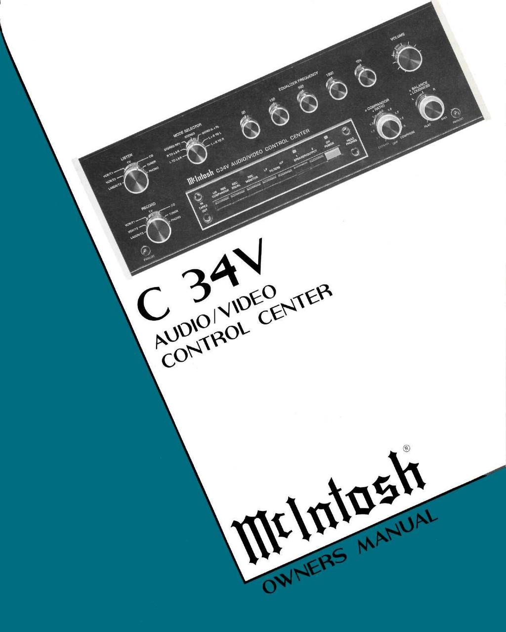
6 This manual will help you to install, operate, and understand your Audio/Video Control Center. Read it and become familiar with it to enjoy it to the fullest. Mclntosh has earned world renown for its technological contributions for improved sound. When you bought Mclntosh, you bought not only high technology, you bought technological integrity proven by time. The Mclntosh Audio/Video Control Center is the newest evidence of Mclntosh technological integrity. Music reproducing instruments that carry the Mclntosh name have always been designed for technological leadership and to maintain the Mclntosh reputation for best sound, for durability, and for long life. Mclntosh has always earned the foremost reputation for quality performance. Mclntosh has provided user oriented facilities and appearance and Mclntosh design always provides for ease of maintenance or repair. These fundamental elements are incorporated in the Mclntosh Audio/Video Control Center, the easiest to operate yet most complex ever. Your Mclntosh C 34V Audio/Video Control Center, above all others will deliver to you the best sound, the most flexibility, and the greatest ease of use. The Mclntosh C 34V is a superb quality, high performance Audio control center. With the MVS-1 Video Selector, the C 34V will provide both audio and video control. The C 34V has many useful features to enhance your listening and video enjoyment. They include: 1. A dual preamplifier system that provides separate listen and record program control. You may listen to or view one program while you are recording a different program. With the Mclntosh MVS-1 Video Selector, the C 34V will switch video and audio signals for viewing, listening, and recording. 2. Two independent, seven source input selector switches permit different audio (or video with the MVS-1) programs to be selected. 3. A low noise, electronic input switching system adjacent to the input jacks gives greater source to source isolation, low audio distortion, and freedom from noise and hum pick-up. The input selector electronic switching signals control the video switching in the MVS The record monitor switch allows the recorded program to be heard through the MAIN output, and, with the MVS-1, the recorded video signals to be seen on a TV or monitor. 5. A five band program equalizer adjusts and improves the loudness contrast of the five most important frequency ranges. Musical balance can be adjusted to compensate for listener preferences. 6. A precision output volume control is electronically trimmed during manufacture to maintain channel balance accuracy to a fraction of a decibel (db). This high order of accuracy assures continuing program balance as the volume is changed. 7. An active circuit loudness control, is electrically independent of the volume control. Close conformity to the Fletcher-Munson equal loudness curves can be attained, regardless of the volume control position. 8. High and low frequency filters reduce high frequency noise and low frequency rumble at a 12 db per octave roll off rate. 9. A compandor expands or compresses the dynamic range of the program material. Compressed recordings and broadcasts can be expanded to restore dynamic range. Tapes can be compressed and replayed using expansion to improve signal-to-noise ratio. 10. Front panel tape recorder jacks which allow simple plug-in of an additional tape recorder without disconnecting your regular system. 4 INTRODUCTION
7 SIMPLIFIED BLOCK DIAGRAM 5

 deep, 17 inches (43.2 cm) wide, and 8 inches (20.32 cm) high. Never place it above heat generating components.")
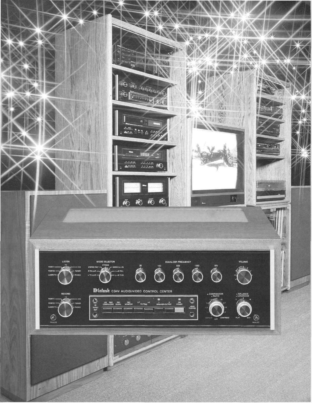
8 PLAYER LOCATION The C34V may be installed in a Mclntosh cabinet or custom installed in furniture of your choice. Always provide adequate ventilation. The trouble-free life of an electronic instrument is greatly extended by providing sufficient ventilation to prevent the buildup of high internal temperatures that cause deterioration. Allow enough clearance so that cool air can enter at the bottom of the cabinet and be vented from the top. The recommended minimum space for installation is 15 5/8 inches (39.7 cm) deep, 17 inches (43.2 cm) wide, and 8 inches (20.32 cm) high. Never place it above heat generating components. CUSTOM INSTALLATION The PANLOC system of installing equipment conveniently and securely, is a product of Mclntosh research. The PANLOC buttons on the front panel will lock the unit firmly in place when turned approximately one-quarter turn clockwise. A one-quarter counterclockwise turn of the PANLOC buttons unlocks the chassis from its mounting. To install the instrument in a Mclntosh cabinet, follow the instructions that are enclosed with the cabinet. For any other type of installation follow these instructions: 1. Unpack from Carton Open the carton and remove the PANLOC brackets, hardware package, and mounting template. Remove the instrument from its plastic bag and place it upside down on the shipping pallet. Unscrew the four plastic feet from the bottom of the chassis. 2. Mark the Cabinet Panel Tape the mounting template in position on the cabinet panel where the instrument is to be installed. The broken lines that represent the outline of the rectangular cutout also represent the outside dimensions of the chassis. Make sure these lines clear shelves, partitions, or any equipment. With the template in place, first mark the six A and B holes and the four small holes that locate the corners of the cutout. Then, join the four corner markings with pencil lines, using the edge of the template as a straightedge. 3. Drill Holes Use a drill with a 3/16 inch (5 mm) bit held perpendicular to the panel and drill the six A and B holes. Then, using a drill bit slightly larger than the tip of your saw blade, drill one hole at each of two diagonally opposite corners. The holes should barely touch the inside edge of the penciled outline. Before taking the next step, make sure that the six A and B holes have been drilled. 4. Saw the Panel Cutout Saw carefully on the inside of the penciled lines. First make the two long cuts and then the two short cuts. After the rectangular opening has been cut out, use a file to square the corners and smooth any irregularities in the cut edges. 6 INSTALLATION
 screws; for panels that are more than 1/2 inch (12.7 rnrn) thick, use the 1-1/4 inch (31.8 mm) screws.")
9 5. Install the Mounting Strips In the hardware package you will find two mounting strips, and two sets of machine screws. For panels that are less than 1/2 inch (12.7 mm) thick, use the 3/4 inch (19.1 mm) screws; for panels that are more than 1/2 inch (12.7 rnrn) thick, use the 1-1/4 inch (31.8 mm) screws. Starting at the right-hand side of the panel, insert a screw of the proper length into the center hole in the panel, marked B on the template. On the back of the panel, align a mounting strip with the holes in the panel and tighten the screw until the screwhead is pulled into the wood. Repeat this procedure to attach the mounting strip to the left side of the panel. 6. Attach the PANLOC Brackets Using two screws of the proper length in the A holes on each side, attach the PANLOC brackets to the cabinet panel; the short flange is mounted against the front (face) of the cabinet panel. The screws pass through the PANLOC bracket flange, the cabinet panel, and then through the mounting strips previously mounted. the cabinet. Turn the PANLOC buttons counterclockwise to unlock the instrument. It can then slide outward to permit the removal of the instrument from the cabinet. 7. Install the Instrument Guide the AC power cord through the panel opening to the back of the cabinet; then, slide the instrument into the opening carefully so that the rails on the bottom of each side of the chassis engage the tracks on the mounting brackets. Continue to slide the instrument into the cabinet until the front panel is flush with the cabinet panel. Turn the PANLOC buttons at the lower left and right corners of the instrument panel clockwise to lock the unit firmly in INSTALLATION 7
10 Fold out the photographs on the inside of the back cover. It will assist you in locating the controls and pushbuttons. The numbers and letters on the photographs refer to the paragraphs that follow. There are four fields of audio connectors on the back panel of the C 34V for use with associated equipment: AUDIO INPUTS, EXTERNAL PROCESSORS, AUDIO OUTPUTS, and MONITOR AMPLIFIER. On the front panel are four additional phone jacks; two for use with an additional audio tape recorder and two for use with headphones. Use shielded cables to interconnect the source equipment and the preamplifier, To minimize the possibility of hum or noise, the shielded cables should be of parallel construction or if not loosely twist the left and right cables together. Locate them away from the speaker connecting cables and AC power cords. Be certain to use good quality shielded cables for all interconnections. Your dealer can advise you on the kind and length of cable that will best suit your installation. AUDIO INPUTS 1. TURNTABLE: Connect the cable from the turntable left channel to the Left PHONO INPUT. Connect the cable from the turntable right channel to the Right PHONO IN- PUT. If the turntable has a separate ground lead, connect it to the screw terminal marked ground (GND). 2. TUNER: Connect the cable from the tuner left channel output to the Left TUNER INPUT. Connect the cable from the tuner right channel output to the Right TUNER INPUT. 3. CD: Connect the cable from the Compact Disc (CD) player left channel output to the Left CD INPUT. Connect the cable from the CD player right channel output to the Right CD INPUT. 4. TV: Audio from a stereo TV set or TV monitor can be connected to the TV INPUT. Connect the left channel cable to the Left TV INPUT. Connect the right channel cable to Right TV INPUT. The output of a monophonic TV set can be connected to both left and right channel TV INPUTS by use of a "Y" connector. 5. VCR 1/TAPE 1: To Playback/Monitor: connect the cable from the tape recorder left channel output to the Left VCR 1/TAPE 1 INPUT. Connect the cable from the tape recorder right channel output to the Right VCR 1/TAPE 1 INPUT. Connect a second and third recorder in the same manner to the VCR 2/TAPE 2 INPUT and LASER/TAPE 3 INPUT. To Record: connect the cable from the Left VCR 1/TAPE 1 OUTPUT to the left high-level input of the tape recorder. Connect the cable from the Right VCR 1/TAPE 1 OUTPUT to the right input of the tape recorder. Connect a second and third recorder in the same manner to the VCR 2/TAPE 2 OUTPUT and TAPE 3 OUTPUT. M. FRONT PANEL TAPE RECORDER JACKS: TAPE 3 recorder input and output connections are also available at the TAPE 3 IN-OUT phone jacks on the front panel. The front panel phone jacks are designed for use with ¼-inch stereo phone plugs. Connections are tip: left signal, ring: right signal, and sleeve: common ground. When a phone plug is inserted in the front panel TAPE 3 in phone jack, the circuit to the rear panel LASER/TAPE 3 INPUT is disconnected, but inserting a phone plug in the front panel TAPE 3 OUT phone jack does not disconnect the rear panel TAPE 3 OUTPUT. Thus, it is possible to record from the front panel TAPE 3 OUT phone jack and the rear panel TAPE 3 OUTPUT at the same time but it is not possible to listen to both at the same time. 6. VCR I/TAPE 1 - VCR 2/TAPE 2: Video Tape Recorders: If you prefer, one or both of the VCR/TAPE inputs can be used for the audio from a VCR. Connect the left channel audio output from the VCR to the Left VCR 1/TAPE 1 INPUT. Connect the right channel audio output from the VCR to the Right VCR 1/TAPE 1 INPUT. If the VCR has only a single audio output (mono), use a "Y" connector to connect the program to both the left and right input. 7. LASERVISION PLAYER: The audio from a laser vision video disc player can be connected to the LASER/TAPE 3 INPUT if desired. Connect the cable from the left channel audio output of a laser disc player to the Left LASER/TAPE 3 INPUT. Connect the cable from the right channel audio output of a laser disc player to the Right LASER/TAPE 3 INPUT. 8. EXTERNAL PROCESSORS: The second field of connectors are marked EXTER- NAL PROCESSORS. There are two sets of EXTERNAL PROCESSOR jacks, one set that affects the program selected by the LISTEN selector and one set that af- 8 HOW TO CONNECT
11 fects the program selected by the RECORD selector. These jacks are used to add a noise reduction or any audio signal processing device. Be sure to match the left to left and right to right channels when connecting external processors. The EXTERNAL PROCESSOR jacks have switching contacts which allow the signal to pass through them when there is nothing plugged into the jacks, When an external processor is used, the program is routed to the external processor from the EXTER- NAL PROCESSOR TO jack and back by the EXTER- NAL PROCESSOR FROM jack. WHEN AN EXTERNAL PROCESSOR IS USED, IT MUST BE TURNED ON FOR THE PROGRAM TO BE HEARD THROUGH THE SYSTEM. 9. AUDIO OUTPUT: The third field of connectors are marked AUDIO OUTPUT. Three sets of jacks (VCR 1/TAPE 1, VCR 2/TAPE 2, and TAPE 3) connect the program selected by the RECORD input selector. The MAIN set of jacks connect the program selected by the LISTEN input selector and connect to the power amplifier. Output to the two sets of jacks (SWITCH- ED 1 and SWITCHED 2) controlled by the front panel SPEAKER/OUTPUT 1 and 2 pushbuttons can be connected to additional power amplifiers for remote area listening. The Left MAIN jack is to be connected to the amplifier left input jack. The Right MAIN jack is to be connected to the amplifier right input jack. Two additional stereo power amplifiers may be connected in the same fashion to the SWITCHED OUTPUT jacks. Audio output signal is supplied to these jacks only when the front panel pushbutton SPEAKER/OUTPUT 1 and/or 2 pushbuttons are pressed in. This arrangement is useful to turn the program on or off to its separate amplifiers and loudspeakers. 10. MONITOR AMPLIFIER: The MONITOR AMPLIFIER provides power to headphones. It may also be used to drive speakers. The MONITOR AMPLIFIER will furnish 20 watts per channel across 8 ohms or 12.6 volts RMS to a 600 ohm line. For operation, see MONITOR AMPLIFIER page 13. The input to the MONITOR AMPLIFIER can be selected from either the RECORD program, the LISTEN program, or from a third source connected to the EXTernal INPUT jacks on the rear panel. The input selector switch is on the top panel of the C 34V. The EXTernal INPUT May be used for program sources not originating in the C 34V. One use could be to connect the output of a time delay device for back channel speakers. The output of the MONITOR AMPLIFIER is fed to the front panel HEADPHONE phone jacks, to the red and black posicontact push connectors and to the jacks marked OUTPUT. Connect the left speaker lead to the black COMmon push connector and the red L terminal. Connect the right speaker lead to the black COMmon push connector and the red R terminal. The OUTPUT jacks can be connected to drive a low impedance (8 to 600 W) unbalanced line. 11. GROUND: The ground (GND) post on the rear panel is provided primarily for a turntable or record changer that has a separate ground lead in addition to the signal leads. 12. AC POWER: Plug the preamplifier AC power cord into a 120 volt 60 Hz wall outlet. The plug blades are polarized so be certain the plug is fully inserted in the outlet to prevent blade exposure. CAUTION: TO PREVENT ELECTRIC SHOCK, DO NOT USE THE (POLARIZED) PLUG ON THIS UNIT WITH AN EXTENSION CORD, RECEPTACLE, OR OTHER OUTLET UNLESS THE BLADES CAN BE FULLY INSERTED TO PREVENT BLADE EXPOSURE. Three types of AC power outlets are provided on the back panel of the C 34V. Three are black, two are red, and one is green. The black outlets are switched on or off when the C 34V is turned on and off. Use these to provide AC power to amplifiers, CD players, or other accessories. The power capacity of all the outlets, totalled, is 1440 watts. The green outlet has a maximum capacity of 100 watts. For power consumption above 1440 watts, it is necessary to add a Mclntosh SCR 2 (SPEAKER CONTROL RELAY). The SCR 2 has two AC power outlets that provide additional capacity of 1800 watts switched on or off by the C 34V. Use these outlets to supply AC power to amplifiers or other components whenever the total load to be switched exceeds the C 34V rating of 1440 watts. The red outlets are on at all times and are used with accessories that have their own power switches. For example, a VCR should be plugged into one of these outlets for it to be able to record TV programs when the main audio system is turned off. HOW TO CONNECT 9
12 The green AC power outlet is on at all times and is used for turntable power. Do not use this outlet for any other purpose. When the turntable power cord is plugged into the green AC outlet, the turntable can be used as an alternate way to switch the AC power to the entire system on or off. When the turntable power is turned on, a sensor circuit in the C 34V will detect the current drain of the turntable motor and will turn on the C 34V the same way the red POWER pushbutton does. The red power pushbutton must be in the OFF or out position. As long as a turntable is connected to the green AC outlet, the turntable current will always override the red POWER pushbutton and turn the system on. Some turntables draw the same or very nearly the same current whether on or off. AUTO TURN-ON control is not possible with this type of turntable. Use one of the red unswitched AC outlets instead of the green. 13. FUSE: A 1.0 AMP fast-acting fuse protects the C 34V turntable current sensing circuits and the green AC turntable outlet. This fuse must be replaced with the same type and rating 1.0 AMP fast-acting fuse. Do not use SLO BLO fuses. The fuse does not protect equipment connected to the black AC outlet. 14. OPTIONAL ACCESSORIES: ADDITIONAL AC POWER AND SPEAKER SWITCHING WITH THE SPEAKER CONTROL RELAY The SPEAKER CONTROL RELAY, or SCR 2, is designed to provide both speaker control switching and high power switched AC outlets. The SCR 2 also has two AC power outlets that provide additional capacity of 2400 watts switched by the C 34V. Use these outlets to supply AC power to amplifiers or other components when the total load switched exceeds the C 34V rating of 1440 watts. Plug the 4-prong plug on the cable attached to the SCR 2 into the SCR 2 socket on the rear of the C 34V. Plug the SCR 2 heavy, AC power line cord directly into a wall outlet. Do not plug it into the C 34V. When the C 34V is turned on, power from the C 34V will energize a relay in the SCR 2 which connects the two SCR 2 AC outlets directly to the wall outlet. Two loudspeakers can be turned on or off with the SCR 2 by using the front panel pushbuttons SPEAK- ER/OUTPUT 1 and 2. Use the TO MAIN SPEAKERS terminal strip to connect the main listening pair of speakers and TO REMOTE SPEAKER terminal to a remote area pair of speakers. Connect the power amplifier output to FROM POWER AMPLIFIER terminal strip. Maintain left and right orientation and like polarity. Pushbutton SPEAKER 1 will turn the main speakers on or off and SPEAKER 2 pushbutton will turn the remote speakers on or off. 15. VIDEO SELECTOR: The Mclntosh VIDEO SELECTOR, MVS-1, is designed to enable the C 34V to control video programs as well as audio. The MVS-1 connects to the VIDEO SELECTOR computer-type connector on the rear of the C 34V. Follow the instruction packet with the MVS-1 for connecting the video cables, 10 HOW TO CONNECT
13 Fold out the photographs on the inside of the back cover. It will assist you in locating the controls and pushbuttons. The letters on the photographs refer to the paragraphs that follow. Before attempting to operate your C 34V Audio/Video Control Center, familiarize yourself with the controls and what they do. A. LISTEN AND RECORD SELECTOR SWITCHES The LISTEN Input selector switch is located at the upper left on the front panel. It is used to select the input for the LISTEN program line. The selected program source is fed to the MAIN output. The RECORD input selector switch is located at the lower left on the front panel. It is used to select the input for the RECORD program line. The selected program source is fed to the TAPE 1, TAPE 2, and TAPE 3 outputs. The RECORD and LISTEN switches operate totally independently of each other and without any interference. B. MODE SELECTOR The MODE SELECTOR allows you to identify each stereo channel, create monophonic program material, and direct program material to one channel or the other. The MODE SELECTOR operates only in the LISTEN program line. It controls the program in seven ways: L TO L&R: Connects the left input to both left and right output circuits. R TO L&R: Connects the right input to both left and right output circuits. STEREO REV: Connects the left input to the right output circuit and the right input to the left output circuit. STEREO: Connects the left input to the left output circuit and the right input to the right output circuit. Use the STEREO position for normal listening. MONO (L + R): Adds the left to the right input and connects the composite to both left and right output circuits. L + R TO L: Connects the left plus right program to the left output circuit only. L + R TO R: Connects the left plus right program to the right output circuit only. C. EQUALIZER FREQUENCY CONTROLS Each of five EQUALIZER FREQUENCY controls raises or lowers the amplitude of a band of frequencies centered on the frequency marked above the control. Both left and right channels are affected. The center, or flat position of the control has a detent for easy reference. In the center or detent position, the entire circuit for that control is removed from the program circuit by grounding the control electronically. The result is the "straight wire with gain" or the flexibility of complete musical balancing to your taste. Use the EQUALIZER FREQUENCY controls to modify the sound and balance of program material. Here are some suggestions: Adjustment to Equalizer Correction Make deep bass louder Make all bass louder Reinforce voices Hum on program Brighten violins and trumpets Emphasize cymbals Raise 30 Raise 30 and 150 Lower 150 and raise 500 Reduce 30 and 150 Raise 1500 Raise 10 K The EQUALIZER FREQUENCY controls can be switched to either the LISTEN or RECORD program lines by the RECORD EQUALIZER pushbutton. Because the equalizer is in the circuit after the COM- PANDOR, use of the equalizer will not affect the performance characteristics of the COMPANDOR. D. BALANCE AND LOUDNESS The BALANCE and LOUDNESS controls are concentric. The BALANCE control (large outer knob) adjusts the volume of the channels relative to each other. L-left...turning the control to the left accents the left channel by reducing the right channel output. R-right...turning the control to the right accents the right channel by reducing the left channel output. E. LOUDNESS The LOUDNESS control (small center knob) provides frequency response contoured to compensate for the behavior of the human ear at lower listening levels. This contour is accurately modeled after the family of "equal loudness" curves identified by Fletcher and Munson. At the fully counterclockwise detented FLAT position, the loudness contour is electrically flat. As the control is turned clockwise, both bass and treble frequencies increase in the correct proportion. The contour is not affected by different settings of the VOLUME control. After setting the VOLUME control for the desired listening level, adjust the LOUDNESS control for the preferred compensation. F. COMPANDOR SYSTEM: The Mclntosh COMPANDOR System can be used to control the dynamic range of program material. It can be used in two different ways: to function as an FRONT PANEL CONTROLS 11
14 expander or as a compressor. Expansion can restore the dynamic range limited by the process of recording both records and tape or broadcasting of music. Compression decreases dynamic range. It can be used for making tape recordings or for listening to background music. The Compandor can be switched to either the RECORD or LISTEN lines, by means of the COMPANDOR pushbutton. The Compandor System has four controls. The concentric three-position COMPANDOR switch and RATIO control are located on the front panel. The LEVEL MATCH control and SPEED selector are located on the C 34V top panel. COMPANDOR SELECTOR The outer COMPANDOR knob can be set to EX- PAND, OFF, or COMPRESS. When the COMPAN- DOR switch is in EXPAND or COMPRESS, a red light will appear above the LISten-or RECord COM- PANDOR pushbutton. In the center OFF position, the Compandor System is switched out of the circuit and the lights will be out. When the Compandor is not used, the selector should be placed in the OFF position. RATIO CONTROL The inner RATIO knob is used to control the amount of expansion or compression. LEVEL MATCH The LEVEL MATCH control on the top panel is used to adjust the listening level when the expander or compressor is switched in or out of the circuit. SPEED The SPEED selector on the top panel is used to control the rate at which the Compandor System responds to signals. By switching from FAST to NOR- MAL to SLOW, a more gradual rate of change in expansion or compression occurs. For music with percussive instruments, such as piano, drums, guitar, etc., use NORMAL or FAST. In the FAST mode, the Compandor System follows changes quickly but will track low frequencies less accurately. Nonpercussive music and voice require slower speed. At SLOW speed the low frequency tracking is accurate, but the rate of response is slower. The NOR- MAL position is best suited for most program material. USING THE COMPANDOR AS AN EXPANDER When the COMPANDOR selector switch is in the EXPAND position, the RATIO control is used to select the amount of expansion. Full counterclockwise rotation corresponds to a ratio of 1.0. This means that the dynamic range of the expander output is the same as the dynamic range of its input. With the VOLUME control at a normal listening level, the RATIO control is turned clockwise, the output dynamic range becomes greater than the input. Set the RATIO control to the desired expansion (usually between 1.2 and 1.5). Now switch the COMPANDOR selector knob between EXPAND and OFF. A change in the average listening level will usually be heard. Adjust the LEVEL MATCH (on the top panel) control until the average listening levels match as closely as possible when in EXPAND and OFF. After this adjustment, you will notice that with the expander on, loud passages will be louder and soft passages will be softer tending to make any background noise quieter. When the RATIO control is at the fully clockwise position, it corresponds to a ratio of 2.0. The output dynamic range is then twice the input dynamic range. This setting is extreme for most program material. USING THE COMPANDOR AS A COMPRESSOR When the COMPANDOR selector switch is in the COMPRESS position, the RATIO control is used to select the reduction in dynamic range desired. Full counterclockwise rotation corresponds to a ratio of 1.0. The compressor output and input dynamic range will be the same. Set the VOLUME control to a normal listening level. As the RATIO control is turned clockwise, the output dynamic range becomes less than the input range. Set the RATIO control to the desired amount of compression. Switch the COMPANDOR selector knob between COMPRESS and OFF. A change in the average listening level will usually be heard. Adjust the LEVEL MATCH control until the average listening levels match as closely as possible when switching between COMPRESS and OFF. After this adjustment, you will notice that with COMPRESS on, loud passages will be softer and soft passages will be louder. When the RATIO control is at the fully clockwise position it corresponds to a ratio of 2.0. The output dynamic range is then one half of the input range. This setting can be useful to create highly compressed tape recordings particularly useful in noisy locations such as automobiles, etc. Two examples for using the expander are: 1. To reduce background noise (hum, hiss or scratch): a. Select the desired program source with the 12 FRONT PANEL CONTROLS

15 LISTEN input selector. b. Increase the VOLUME control during a quiet passage of the program until noise is clearly audible. c. Turn the COMPANDOR selector knob to EX- PAND. The Listen indicator will light over the COMPANDOR pushbutton. d. Rotate the RATIO control clockwise until the noise is acceptably reduced. e. Adjust the LEVEL MATCH control as previously described. 2. To improve the sound of recorded or broadcast program material: a. Select the input on the LISTEN input selector. b. Increase the VOLUME to a satisfactory level. c. Turn the COMPANDOR selector switch to EXPAND. d. Rotate the RATIO control clockwise until the dynamic range of the music is satisfactory for you. The usual position will be between 1.2 and 1.5. e. Adjust the LEVEL MATCH control as previously described. TOP PANEL CONTROLS COMPANDOR Operation of the LEVEL MATCH and SPEED controls is explained on page 12. See the Compandor System description. MONITOR AMPLIFIER The built-in MONITOR AMPLIFIER can drive headphones, loudspeakers, or provide a low impedance line output. A top panel input position switch selects the input for the MONITOR AMPLIFIER. The sources are the LISTEN program line, the RECORD program line, or any high level EXTERNAL source. When using headphones plugged into the front panel jacks, the normal position is LISTEN. The monitor amplifier LEFT and RIGHT CAIN controls are located to the left of the INPUT switch on the top panel. When the switch is in the LISTEN position, the LEFT and RIGHT GAIN controls regulate the monitor volume along with the main front panel VOLUME control. When the INPUT switch is in the RECORD or EX- TERNAL position, only the LEFT and RIGHT GAIN controls regulate the monitor amplifier volume. The monitor amplifier can be used with any low impedance dynamic headphones. High impedance headphones will work but at reduced listening levels. FRONT PANEL CONTROLS 13
16 G. COMPANDOR The COMPANDOR pushbutton switches the COMPANDOR circuits between the LISTEN (out position) and RECORD (in position) program lines or disconnects the circuit entirely. A red light emitting diode (LED) illuminates to indicate when the circuit is connected to either Listen or RECord. When neither is lit, the COMPANDOR selector knob is turned to the OFF position. H. RECord EQUAL The EQUALIZER FREQUENCY pushbutton connects these controls to the LISTEN or RECORD program lines. When the pushbutton is out, the EQUALIZER FREQUENCY controls are connected to the LISTEN line, and the red LED indicator above the button is off. When the pushbutton is in, they are connected to the RECORD line. The red LED indicator will be on. The normal position is with the pushbutton out. 1. RECord MONITOR To monitor while recording with a three-head tape recorder, set the LISTEN input selector to the proper TAPE position. The RECord MONITOR LED indicator is off when listening to the program recorded on the tape and on when listening to the program source being fed to the tape recorder. J. LF FILTER The Low Frequency FILTER is in the LISTEN program line only. When the pushbutton is out, the filter is out of the circuit and the red indicator light will be off. When the pushbutton is in, the LF FIL- TER is in the circuit and the red light will be on. The filter is effective for all frequencies below 50 Hz and attenuates at the rate of 12 db per octave. Use it to reduce undesirable low frequency noise such as rumble or mechanical feedback. K. HF FILTER The High Frequency FILTER is in the LISTEN program line only. When the pushbutton is out, the HF FILTER is out of the circuit and the red indicator light is off. When the pushbutton is in, the HF FIL- TER is in the circuit and the red light is on. The filter is effective for all frequencies above 7,000 Hz and attenuates at the rate of 12 db per octave. Use it to reduce undesirable high frequency noise such as record surface noise or tape hiss. L. SPEAKER/OUTPUT 1 and 2 The SPEAKER/OUTPUT 1 and 2 pushbuttons can be used to switch on or off either the AUDIO OUT- PUT SWITCHED 1 and 2 jacks or the main and remote speakers when an optional Speaker Control Relay (SCR 2) is used. The SWITCHED 1 and 2 jacks on the rear panel of the C 34V have the same program as the MAIN OUTPUT. When one or both SPEAKER/OUTPUT pushbuttons are IN, the LISTEN program line is connected to the corresponding pair of OUTPUT jacks and the LED indicator is turned on. Program to other devices can be controlled such as rear channel delay, reverberation, etc. Example: connect the SWITCHED 1 jack to the input of a reverberation device and the output of the reverberation device to the input C 34V MONITOR AMPLIFIER and the output of the MONITOR AMPLIFIER to a set of rear loudspeakers. (The monitor amplifier switch must be in the EXTERNAL position.) Rear channel reverberation can then be switched on or off by the SPEAKER OUTPUT 1 pushbutton without the need for an additional amplifier. N. POWER ON The red pushbutton turns the C 34V on or off. When the power is on, the panel illuminates and the red light above this pushbutton will go on. The turntable can also be used as a power switch. See page PUSHBUTTONS
17 PERFORMANCE LIMITS Performance limits are the maximum deviation from perfection permitted for a Mclntosh instrument. We promise you that when you purchase a new C 34V from a Mclntosh franchised dealer, it will be capable of or can be made capable of performance at or exceeding these limits or you can return the unit and get your money back. Mclntosh is the only manufacturer that makes this statement. PREAMPLIFIER SECTION FREQUENCY RESPONSE + 0, -0.5dB from 20Hz to 20,000Hz MAXIMUM VOLTAGE OUTPUT 10 volts from 20Hz to 20,000Hz TOTAL HARMONIC DISTORTION 0.01% maximum from 20Hz to 20,000Hz at rated output SENSITIVITY Phono- 2mV for 2.5V rated output (0.4mV IHF) High Level- 250mV for 2.5V rated output (50mV IHF) SIGNAL TO NOISE RATIO, A-WEIGHTED Phono- 90dB below 10mV input (84dB IHF) High Level- 100dB below rated output (86dB IHF) MAXIMUM INPUT SIGNAL Phono- 100mV High Level- 10 volts INPUT IMPEDANCE Phono- 47k ohms and 65pf capacitance High Level- 50k ohms EQUALIZATION CONTROLS Variable 12dB boost to 12dB cut at center frequencies of 30, 150, 500, 1500, 10k Hz COMPANDOR RATIOS From 1:2 compression to 2:1 expansion LF FILTER Flat or roll-off at 12dB per octave below 50 Hz. HF FILTER Flat or roll-off at 12dB per octave above 7,000 Hz. 20kHz, at 0.01% maximum harmonic distortion FREQUENCY RESPONSE dB from 20Hz to 20,000Hz SENSITIVITY 750mV for rated output (170mV IHF), input impedance is 27K ohms SIGNAL TO NOISE RATIO, A-WEIGHTED 100dB below rated output (87dB IHF) GENERAL INFORMATION SEMICONDUCTOR COMPLEMENT 31 Bipolar Transistors 76 Field Effect Transistors 35 Integrated Circuits 107 Diodes 1 Silicon Controlled Rectifier (SCR 2) AC POWER OUTLETS 1 green turntable current sensing, 100 watts 2 red unswitched 3 black switched 1440 watts total capacity POWER REQUIREMENTS 120 volts, 50/60 Hz, 25 to 85 watts MECHANICAL INFORMATION SIZE: 16-1/8 inches wide (40.6 cm) by 5-7/16 inches high (13.8 cm) by 13 inches deep (33 cm), from the mounting surface, including PANLOC shelf and back panel connectors. Knob clearance required is 1-1/4 inches (3.2 cm) in front of the mounting panel. FINISH: Front panel is anodized gold and black with special gold/teal nomenclature illumination. Chassis is black. MOUNTING: Exclusive Mclntosh developed professional PANLOC WEIGHT: 26 pounds (11.8 kg) net, 38 pounds (17.2 kg) in shipping carton MONITOR AMPLIFIER SECTION CONTINUOUS AVERAGE POWER OUTPUT 20 watts per channel into 8 ohms, from 20Hz to PERFORMANCE LIMITS 15

18 16 PERFORMANCE CHARTS

19 PERFORMANCE CHARTS 17
20 The simplified block diagram on page 5 and the detailed block diagram on pages 20 and 21 show how the C 34V internal circuits are arranged. The C 34V uses separate program channels (referred to as "program lines" in this manual) for "listening" and "recording". This allows you to listen to any program source while you record from another or the same program source. The mode selector, volume control, loudness control, balance control, and LF and HF filters are in the listen program line only. The compandor, the five equalizer frequency controls, and the monitor amplifier can be individually switched to the listen program line or the record program line. PHONO AMPLIFIER This amplifier uses a high technology integrated circuit operational amplifier. Its differential input stage has been optimized for low noise and low distortion performance. Open loop gain of this integrated circuit is 100,000 times. With high open loop gain a large amount of negative feedback is used around the phono amplifier to further reduce noise and distortion. The feedback network also provides precision RIAA frequency compensation. The network uses 1% metal film resistors and 5% poly film capacitors. To achieve low noise performance it is essential that the feedback network have very low impedance. As a consequence, the preamplifier must be capable of operating as a power amplifier to drive this impedance. The actual power output capability of this preamplifier stage is more than 100 milliwatts, a great margin beyond that which is required. Input sensitivity of the phono amplifier is 2.2 millivolts. The gain of the amplifier is 42 db at 1000 Hz. The phono amplifier has a very wide dynamic range. At 1000 Hz the phono input circuit will accept 100 millivolts without overload, a voltage far greater than the output of any magnetic phono cartridge presently available. LISTEN AND RECORD SELECTOR SWITCHES Input switching is accomplished electronically. Signals from the 7 inputs connect to two arrays of Field Effect Transistors (FET) to perform the switching. Control signals from the listen and record selector switches turn on the appropriate FET switches to pass the selected input signals. The other input signals are blocked by the "off" FET switches. Each FET switch uses two cascaded FET transistors to provide the required isolation and prevent cross talk between inputs. The FET "on" resistance is very low which prevents distortion. The switching transistors are located right at the input jacks, so that signal wiring is kept to a minimum which eliminates cross talk and noise problems. LISTEN PROGRAM LINE The listen program signal from the LISTEN input switch goes to the COMPANDOR control switching where the COMPANDOR can be inserted in either the listen or the record program path. The COMPANDOR circuit is described later. The listen program then goes to the LISTEN EXTER- NAL Processor jacks. When an EXTERNAL PROCESSOR is used, the listen program leaves the C 34V through the EXTERNAL processor TO jack and returns via the FROM jack. If a processor is not used, the signal passes directly through the switching contacts In the jacks. The volume control is next in the listen path. It is a step attenuator with left to right tracking accuracy better than 1 db throughout its entire range. Such extremely accurate matching is achieved through electronically controlled trimming of the resistance material deposited on pairs of printed circuits within the control. Since the switch commutator touches only contact pads and not the actual resistance element, tracking accuracy is not degraded with use as in ordinary volume controls. The loudness control and its amplifiers follow the volume control. In the past, loudness controls have typically been simple passive circuits connected to a tap on the volume control. As a consequence, compensation accuracy was dependent on many variables such as volume control position and differences in the input level. The C 34V loudness control uses active circuits of an integrated circuit operational amplifier with two feedback loops. One has flat frequency response, while the other has response conforming to the Fletcher-Munson equal loudness contours. A potentiometer is placed between these two feedback loops making it possible to select any combination of the two, from a flat response to full loudness compensation. The overall gain of the stage is 20 db at mid-frequencies and the average listening volume is not affected by the position of the loudness control. The listen program signals next pass to the balance control and then to the equalizer amplifier composed of a low noise operational amplifier with flat response and unity gain. Five other operational amplifiers are arranged in circuit configurations that are equivalent to five series tuned circuits, each at one of the equalizer frequencies. These series tuned circuits are inserted via control potentiometers into either the input circuit or feedback circuit of the equalizer amplifier to provide a boost or cut capability of 12 db for each equalizer band 18 TECHNICAL DESCRIPTION
21 of frequencies. A pushbutton switch allows the equalizer circuit to be switched from the listen program line to the record program line. The LF and HF Filters follow the equalizer amplifier. These are active filters using operational amplifiers. When switched in, the LF filter attenuates frequencies below 50 Hz at a rate of 12 db per octave. The HF Filter attenuates frequencies above 7 khz at a rate of 12 db per octave. The listen program signal then is fed to the main output jacks. The OUTPUT 1 and OUTPUT 2 jacks receive the same signal but can be turned on or off by the Speaker/Output 1 and 2 pushbuttons. RECORD PROGRAM LINE The RECORD program signal from the RECORD input switch goes first through a unity gain amplifier and then to the COMPANDOR switching where the Compandor can be inserted into the record program path. The Compandor circuit is described later. The record program then goes to the RECORD EXTERNAL PROCESSOR jacks. These jacks, like the LISTEN EXTERNAL PRO- CESSOR jacks, have switching contacts so that the signal passes through when plugs are not inserted in the jacks. When an external processor is used, the record program leaves the C 34V through the EXTERNAL PRO- CESSOR TO jack and returns via the FROM jack. When a processor is not connected, the signal passes directly through the jacks. An equalizer amplifier with unity gain follows. A pushbutton switch allows the 5 band equalizer controls to be switched from the Listen program line to the Record program line. This feature allows equalizing the record signal before it is fed to a recorder. The equalizer amplifier feeds to electronic interlock switching and then finally to the record output jacks. The switching is arranged so that if the Record input selector is positioned to select the output of a recorder, the Record program line will not feed the record output jack connected to that recorder. This prevents recorder feedback. COMPANDOR The Compandor will expand or compress the dynamic range of the program material. The Compandor can be switched to the Listen or Record program lines or turned off. Program to the Compandor is applied to a voltage controlled amplifier (VCA) which operates as a variable gain block. Control voltages for this VCA are developed from a sample taken from the left and right channel input signals to the VCA. The electronic processing of this sample is detailed. It includes band shaping, logarithmic conversion, full wave rectification, level setting, expansion or compression ratio regulation, attack timing, and DC amplification. The resulting processed voltage controls the gain of the VCA to cause logarithmic gain expansion when expanding the program, or the opposite, logarithmic gain compression when compressing the program. MONITOR AMPLIFIER The monitor amplifier is a 20 watt per channel stereo power amplifier. The monitor input selector switch allows the amplifier to be driven from the LISTEN or RECORD program lines or from an external input. It is a push pull complementary class AB amplifier using a differential input stage. The amplifier includes the Mclntosh Power Guard* protection circuit. The Power Guard circuit compares the amplifier output signal with its input signal. If there is a difference between the waveforms of these signals, Power Guard activates an electronic attenuator at the input of the amplifier which reduces the amplifier input level. This automatic control system makes it impossible to drive the monitor amplifier into clipping. Thus, clipping distortion and loudspeaker damage due to clipping are eliminated. AUTO TURN-ON A turntable plugged into the green outlet at the rear of the C 34V can control the on-off operation of the C 34V. Current flow to the turntable is sensed and controls a silicon control rectifier (SCR). When the SCR conducts a relay closes. This relay turns on power to the C 34V and to the black AC power outlets. Power is also controlled by the C 34V Power On pushbutton. protected by US Patent # ) TECHNICAL DESCRIPTION 19
22 C 34V 20 BLOCK DIAGRAM
23 BLOCK DIAGRAM 21


24 THE LOCATION OF CONTROLS AND PUSHBUTTONS The numbers and letters correspond to the paragraphs on pages 8, 9, 10, 11 and 12.

25
CR10 REMOTE CONTROL SYSTEM
 CR10 REMOTE CONTROL SYSTEM CR10 REMOTE CONTROL SYSTEM IMPORTANT SAFETY INSTRUCTIONS THESE INSTRUCTIONS ARE TO PROTECT YOU AND THE MclNTOSH INSTRUMENT. BE SURE TO FAMILIARIZE YOURSELF WITH THEM 1. Read
THE MclNTOSH C 504 STEREO PREAMPLIFIER
 THE MclNTOSH C 504 STEREO PREAMPLIFIER Reading Time: 30 Minutes Price: $2.00 VARIOUS REGULATORY AGENCIES REQUIRE THAT WE BRING THE FOLLOWING INFORMATION TO YOUR ATTENTION. PLEASE READ IT CAREFULLY. WARNING:
C 30 STEREO PREAMPLIFIER
 C 30 STEREO PREAMPLIFIER 039493 VARIOUS REGULATORY AGENCIES REQUIRE THAT WE BRING THE FOLLOWING INFORMATION TO YOUR ATTENTION. PLEASE READ IT CAREFULLY. WARNING: TO PREVENT FIRE OR SHOCK HAZARD, DO NOT
SW 50. Powered Subwoofer with Built-in Stereo Crossover
 Owner s Manual SW 50 ed Subwoofer with Built-in Stereo Crossover Congratulations on your new purchase and welcome to the AudioSource family of satisfied customers. We trust you will continue to enjoy the
THE MclNTOSH MQ101 ENVIRONMENTAL EQUALIZER
 THE MclNTOSH MQ101 ENVIRONMENTAL EQUALIZER Price $1.25 Your MQ101 Environmental Equalizer will give you many years of pleasant and satisfactory performance. If you have any questions concerning the operation
Utility Amplifier GA6A Model
 Utility Amplifier GA6A Model Installation and Use Manual 2004 Bogen Communications, Inc. All rights reserved. Specifications subject to change without notice. 54-5757-03D 1503 NOTICE: Every effort was
Technical Specifications
 INSTALLATION SHEET AND OPERATORS MANUAL General Description: The is a mixer/preamplifier that includes 6 channels that each include a microphone input at screw terminals and an aux input at an RCA jack.
BP2-MM MM Phono Preamplifier Owner s Manual
 BP2-MM MM Phono Preamplifier Owner s Manual Important Safety Instructions The lightning flash with arrowhead symbol within an equilateral triangle, is intended to alert the user to the presence of un-insulated
2.0 Wall Mount TV Soundbar Instruction Manual
 8010275 2.0 Wall Mount TV Soundbar Instruction Manual Read all of the instructions before using this soundbar and keep the manual in a safe place for future reference. Safety Information CA UT IO N RISK
SDM1000. Satellite Demodulator Module INSTRUCTION MANUAL SDM Satellite Demodulator Module
 SDM1000 Satellite Demodulator Module INSTRUCTION MANUAL Model Item # Description SDM1000 1002576 Satellite Demodulator Module 937-746-4556 www.rldrake.com 2015 R.L. Drake Holdings, LLC. Rev: 041715 / 651230500A
~ Instruction Manual ~
 ~ DJ-5 Professional Preamp mixer ~ 0 0 0 0 10 10 10 10 EVE MASTE GAIN GAIN 0 10 CUE EVE CH 1 CH 2 CUE PAN INE INE POWE FADE STAT FADE STAT HEADPHONES ~ Instruction Manual ~ ~ Important Safety Instructions
After Ref.No:
 Ref.No:171.130 Safety Instructions 1. Read Instructions-All the safety and operating instructions should be read before this product is operated. 2. Retain Instruction- The safety and operating instruction
C22 Stereophonic Preamplifier Owner s Manual
 McIntosh Laboratory, Inc. 2 Chambers Street Binghamton, New York C22 Stereophonic Preamplifier Owner s Manual 13903-2699 Phone: 607-723-3512 www.mcintoshlabs.com 2 The lightning flash with arrowhead, within
BP2-MM/MC Phono Preamplifier Owner s Manual
 BP2-MM/MC Phono Preamplifier Owner s Manual Important Safety Instructions The lightning flash with arrowhead symbol within an equilateral triangle, is intended to alert the user to the presence of un-insulated
MclNTOSH MODEL C-4 and C-4P
 INSTRUCTION MANUAL MclNTOSH MODEL C-4 and C-4P AUDIO COMPENSATORS McINTOSH LABORATORY, INC. 320 Water St. Binghamton, N. Y. U.S.A. - 1 - INSTRUCTION MANUAL McINTOSH MODEL C-4 and C-4P AUDIO COMPENSATORS
HPA-8 8 Channel Headphone Amplifier. Owner s Manual
 HPA-8 8 Channel Headphone Amplifier Owner s Manual Contents Features... 2 Warning... 3 Installation... 4 Panel Connections, Controls and Indicators... 5 Using the HPA-8... 6 Specifications... 7 With extensive
TS2.8 Sub OWNER S MANUAL
 TS2.8 Sub OWNER S MANUAL TS2.8 Sub CONTENTS IMPORTANT SAFETY INSTRUCTIONS 03 WARNINGS 03 FUSE PROTECTION 04 WARNING: STRONG MAGNETIC FIELD 04 EMC / EMI 04 ECODESIGN STANDBY POWER CONSUMPTION 04 WARRANTY
CVT1030MKII CCVT STEREO PREAMPLIFIER
 NORMAL CVT1030MKII CCVT STEREO PREAMPLIFIER IA Cold Cathode Vacuum Tube design to give superb sound quality AMC proprietary design of operate high voltage FET under Vacuum Tube mode to give warm, soft
LS6100 OWNER'S MANUAL. AM/FM Stereo Receiver and Auto Stop Cassette Player
 OWNER'S MANUAL LS6100 AM/FM Stereo Receiver and Auto Stop Cassette Player Designed for In-Wall Installation of All Recreational Vehicles, Motor Homes and Mobile Housings 12 Volts DC Copyright 1998 Magnadyne
USER MANUAL MX102 & MX1202
 USER MANUAL MX102 & MX1202 WWW.PULSE-AUDIO.CO.UK 1 SAVE THESE SAFETY INSTRUCTIONS Thank you for purchasing our product. To assure the optimum performance, please read this manual carefully and keep it
UHF/VHF/FM Distribution Amplifier TA-36. Installation And Operation Manual. ODoc. No. OM Rev. A ECO 1750 P/N
 TA-36 UHF/VHF/FM Distribution Amplifier Installation And Operation Manual P/N 911069 ODoc. No. OM2190-3 Rev. A ECO 1750 Safeguards Read This First Important Information Product Inspection Inspect the equipment
DM900 BLUE DOG OWNER S MANUAL
 Professional Disc Jockey Products DM900 BLUE DOG OWNER S MANUAL NUMARK INDUSTRIES 11 Helmsman Road, North Kingstown, RI 02852 http://www.numark.com CONGRATULATIONS! You have purchased the DM900 Blue Dog
Monochrome Video Monitors
 Instructions for Use Monochrome Video Monitors En F D E NL I LTC 2009 LTC 2012 LTC 2017 Philips Communication & Security Systems GB F D E NL I Instructions for Use...1.1 Mode d emploi...2.1 Bedienungsanleitung...3.1
PH-1. Italian MM & MC Phono Preamplifier OWNER S MANUAL
 PH-1 Italian MM & MC Phono Preamplifier OWNER S MANUAL IMPORTANT SAFETY INFORMATION CAUTION: TO REDUCE THE RISK OF ELECTRIC SHOCK, DO NOT REMOVE COVER (OR BACK). NO USER-SERVICEABLE PARTS INSIDE. REFER
IMPORTANT SAFETY INSTRUCTIONS
 IMPORTANT SAFETY INSTRUCTIONS When using this electronic device, basic precautions should always be taken, including the following: 1. Read all instructions before using the product. 2. Do not use this
Operating Manual. Mark Levinson Nº25 Dual Monaural Phono Preamplifier. Madrigal Audio Laboratories, Inc. 1
 Operating Manual Mark Levinson Nº25 Dual Monaural Phono Preamplifier Madrigal Audio Laboratories, Inc. 1 WARNING: TO REDUCE THE RISK OF FIRE OR ELECTRIC SHOCK, DO NOT EXPOSE THIS APPLIANCE TO RAIN OR MOISTURE.
POWERED MIXER MPM 4130 OWNER S MANUAL 4 CHANNEL POWERED MIXER
 POWERED MIXER OWNER S MANUAL MPM 4130 4 CHANNEL POWERED MIXER MPM 4130 4 CHANNEL POWERED MIXER Congratulations on your choice of a powered mixer you have purchased one of the finest powered mixers on the
Power Source The equipment should be connected to a power supply only of the type described in this manual or as marked on the equipment.
 Linear 1 Vacuum Tube Preamplifier SAFETY INSTRUCTION To avoid personal injury or damage to equipment, please ensure that you read this manual in its entirety before attempting to operate the equipment.
AC1686 Active Combiner. Instruction Manual
 AC1686 Active Combiner Instruction Manual is a registered trademark of the R.L. Drake Company Copyright 2004 R.L. Drake Co. P/N: 3853620A-5-2004 Printed in the U.S.A. ii Caution Statements WARNING: TO
COHERENCE ONE PREAMPLIFIER
 COHERENCE ONE PREAMPLIFIER OWNER S MANUAL TABLE OF CONTENTS Introduction Features Unpacking Instructions Installation Phono Cartridge Loading Basic Troubleshooting Technical Specifications Introduction
LX20 OPERATORS MANUAL
 LX20 OPERATORS MANUAL CONTENTS SAFETY CONSIDERATIONS page 1 INSTALLATION page 2 INTRODUCTION page 2 FIRST TIME USER page 3 SYSTEM OPERATING LEVELS page 3 FRONT & REAR PANEL LAYOUT page 4 OPERATION page
HDMI 5x1 Switch B-240-HDSWTCH-5X1 INSTALLATION MANUAL
 HDMI 5x1 Switch B-240-HDSWTCH-5X1 INSTALLATION MANUAL IMPORTANT SAFETY INSTRUCTIONS To reduce the risk of fire or electric shock, read and follow all instructions and warnings in this manual. Keep this
110LP MOON Series. Phono Preamplifier. Owner s Manual
 Phono Preamplifier Owner s Manual Owner s Manual I Table of Contents Introduction 4 Unpacking 5 Installation & Placement 5 Circuit Board Layout s 6 Internal Adjustments 7 Rear Panel Connections 8 Operating
SAFETY INFORMATION. 7. Do not force switched or external connections in any way. They should all connect easily, without needing to be forced.
 SAFETY INFORMATION 1. To ensure the best results from this product, please read this manual and all other documentation before operating your equipment. Retain all documentation for future reference. 2.
Color Video Monitor. Instruction Manual. Read this manual thoroughly before use, and retain it for maintenance.
 Color Video Monitor Instruction Manual Read this manual thoroughly before use, and retain it for maintenance. The product s exterior design and specifications may subject to change without prior notice
English. User Manual sub8 Subwoofer SUBWOOFER. Supporting your digital lifestyle
 English User Manual sub8 Subwoofer U SUBWOOFER Supporting your digital lifestyle Table of Contents Important Safety Precautions........ 2 Introduction / What s in the Box?...... 3 Front & Rear Panels............
GIULIA Y. combo amplifier for acoustic instruments
 GIULIA Y combo amplifier for acoustic instruments IMPORTANT SAFETY INSTRUCTIONS THE LIGHTNING FLASH WITH ARROWHEAD SYMBOL, WITHIN AN EQUILATERAL TRIANGLE, IS INTENDED TO ALERT THE USER TO THE PRESENCE
CR-6 MIXER USER MANUAL ENGLISH. Order Code: MIXE01
 CR-6 MIXER P R O F E S S I O N A L 1 9 R A C K M I X E R Order Code: MIXE01 w w w. p r o l i g h t. c o. u k USER MANUAL ENGLISH WARNING FOR YOUR OWN SAFETY, PLEASE READ THIS USER MANUAL CAREFULLY BEFORE
SATRI AMPLIFIER AMP-51R. Owner s Manual
 SATRI AMPLIFIER AMP-51R Owner s Manual contents SAFETY INSTRUCTIONS 4 INTRODUCTION 6 OVERVIEW (FRONT PANEL) 8 OVERVIEW (REAR PANEL) 9 OVERVIEW (REMOTE CONTROL) 1 1 OPERATION 12 TROUBLESHOOTING 13 SPECIFICATION
PCM55SAW 550MHz Single-Channel PLL SAW-filtered A/V Modulator
 550MHz Single-Channel PLL SAW-filtered A/V Modulator Installation and Operation Manual Operation Manual 355 Parkside Drive Rev. 09/02 San F Ph: 818-493-4300 Toll Free: 800- Safeguards Important Information
CLASSIC SERIES POWERED SUBWOOFERS
 O P E R A T I O N M A N U A L CLASSIC SERIES POWERED SUBWOOFERS SAFETY INSTRUCTIONS.............. 2 WARRANTY INFORMATION........... 3 CONTROL DESCRIPTIONS............ 4 CONNECTING SUBWOOFER...........
Phono Amplifier brinkmann «EDISON» Manual.
 Phono Amplifier brinkmann «EDISON» ----------------------------------------------------------------------------------------------- Manual Preface We congratulate you on the purchase of our «EDISON» phono
CR42 LANCASTER
 10-4-08 CR42 LANCASTER 910-262800-0020-100 WARRANTY Crosley Radio Products are warranted against defects in material and workmanship for a period of 90 days beginning from the date of sale to the original
PHC-12G. Installation and Operation Manual. 1 GHz Broadband Passive Headend Combiner. Ph: Operation Manual Rev.
 1 GHz Broadband Passive Headend Combiner Installation and Operation Manual Operation Manual Safeguards Product Inspection Inspect the equipment for shipping damage. Should any damage be discovered, immediately
CONGRATULATIONS CONTENTS
 OWNER'S MANUAL CONGRATULATIONS Thank you for your purchasing the VESTAX PMC-05ProIII, Professional Mixing Controller. We suggest that you read through this owner's manual thoroughly so that you may enjoy
Owner s Manual. Model PH8 Phono Preamplifier
 Owner s Manual Model PH8 Phono Preamplifier 2 Contents Model PH8 Phono Preamplifier Illustrations 4 Preface 5 Warnings 5 Packaging 5 Front Panel Controls 5 6 Remote Control Functions 6 Connections 6 Installation
Operating Manual. Mark Levinson Nº28 Preamplifier. Madrigal Audio Laboratories, Inc. 15
 Operating Manual Mark Levinson Nº28 Preamplifier Madrigal Audio Laboratories, Inc. 15 WARNING: TO REDUCE THE RISK OF FIRE OR ELECTRIC SHOCK, DO NOT EXPOSE THIS APPLIANCE TO RAIN OR MOISTURE. CAUTION RISK
2.4 GHz WIRELESS VIDEO SENDER SYSTEM MODEL: VS6234
 2.4 GHz WIRELESS VIDEO SENDER SYSTEM MODEL: VS6234 Please read this manual thoroughly before operating this system OPERATING INSTRUCTIONS 03/02 1 SAFETY INSTRUCTIONS CAUTION! RISK OF ELECTRIC SHOCK. DO
C Class Signal Processors
 -5-3 -2-7 -1 0-10 -20 +4 VU SAMSON OPTICAL COMPRESSOR A U D I O C Class Signal Processors Safety Instructions Caution: To reduce the hazard of electrical shock, do not remove cover or back. No user serviceable
Owner's Manual. Model PH6 PHONO PREAMPLIFIER.
 Owner's Manual Model PH6 PHONO PREAMPLIFIER 3900 ANNAPOLIS LANE NORTH / PLYMOUTH, MINNESOTA 55447-5447 / PHONE: 763-577-9700 FAX: 763-577-0323 www.audioresearch.com Contents Model PH6 Page No. Preface.......................................................1
DM-1CH SD DVB-T MODULATOR INSTRUCTION MANUAL
 DM-1CH SD DVB-T MODULATOR INSTRUCTION MANUAL 2. Caution Statements and Table of Contents Table of Contents 2. Caution Statements and Table of contents 3. Important Safety Instructions 4. Important Safety
508 Phono Preamplifier. Boulder Amplifiers, Inc. 255 S. Taylor Ave. Louisville, CO (303) /1/2018 Rev. 1.
 /1/2018 Rev. 1.") 508 Phono Preamplifier 6/1/2018 Rev. 1.0 P/N: 91053 Boulder Amplifiers, Inc. 255 S. Taylor Ave. Louisville, CO 80027 (303) 449-8220 www.boulderamp.com About About Boulder Amplifiers, Inc. Boulder was founded
508 Phono Preamplifier 6/1/2018 Rev. 1.0 P/N: 91053 Boulder Amplifiers, Inc. 255 S. Taylor Ave. Louisville, CO 80027 (303) 449-8220 www.boulderamp.com About About Boulder Amplifiers, Inc. Boulder was founded
TB2 Powered Home Subwoofer Owner s Manual
 1 Mitek Plaza Winslow, IL 61089 Phone (877)DCM-LOUD Visit our Internet web site at: www.dcmspeakers.com DCM is a registered trademark of Mitek Corporation. TB2 Powered Home Subwoofer Owner s Manual Due
PROFESSIONAL 2 CHANNEL SOLID-STATE MIC / LINE PREAMPLIFIER USER S MANUAL
 PROFESSIONAL 2 CHANNEL SOLID-STATE MIC / LINE PREAMPLIFIER USER S MANUAL SAFETY INSTRUCTIONS This symbol, wherever it appears, alerts you to important operating and maintenance instructions in the accompanying
Linear200 Intergrated Tube Amplifier
 Linear200 Intergrated Tube Amplifier SAFETY INSTRUCTION To avoid personal injury or damage to equipment, please ensure that you read this manual in its entirety before attempting to operate the equipment.
Wireless 4 Channel Receiver with 2 Night Vision cameras
 Wireless 4 Channel Receiver with 2 Night Vision cameras Instruction Manual English Version 2.0 MODEL: SHS-4WLS www.lorexcctv.com Copyright 2006 LOREX Technology Inc. Thank you for purchasing the SHS-4WLS.
Model 1421 Distribution Amplifier
 Model 1421 Distribution Amplifier Installation and Operating Instructions The 1421 Distribution Amplifier provides four independent, wide bandwidth outputs from one video input. The unit is color compatible
Introduction Front Panel Functions Rear Panel Functions Precautions Placement & Ventilation... 5
 Contents Introduction... 2 Front Panel Functions... 3 Rear Panel Functions... 3 Precautions... 5 Placement & Ventilation... 5 Installation & Operation... 5 Care & Maintenance... 7 Troubleshooting... 8
HD Digital Set-Top Box Quick Start Guide
 HD Digital Set-Top Box Quick Start Guide Eagle Communications HD Digital Set-Top Box Important Safety Instructions WARNING TO REDUCE THE RISK OF FIRE OR ELECTRIC SHOCK, DO NOT EXPOSE THIS PRODUCT TO RAIN
Table of Contents. Read This First.2. Introduction by Jim Fosgate...3. Unpacking..4. Tubes and Tube shield Installation 5. Product Placement...
 Owner s Manual Table of Contents Read This First.2 Introduction by Jim Fosgate...3 Unpacking..4 Tubes and Tube shield Installation 5 Product Placement...6 Connecting your Fosgate Signature..7 Phono stage
ZVOX AccuVoice TV Speaker Model AV203
 ZVOX AccuVoice TV Speaker Model AV203 SETUP & OPERATION www.zvoxaudio.com 2 ZVOX AccuVoice TV Speaker Setup & Operation READ THIS FIRST Important Safety Instructions For ZVOX Audio System WARNING TO PREVENT
OWNER S MANUAL EVOLUTION SERIES POWERED SUBWOOFER ES-SUB-EVO6-100
 OWNER S MANUAL EVOLUTION SERIES POWERED SUBWOOFER ES-SUB-EVO6-100 Important Safety Instructions CAUTION RISK OF ELECTRIC SHOCK! DO NOT OPEN! ATTENTION! RISQUE DE CHOC! ÉLECTRIQUE PAS OUVRIR! The lightning
Summit Audio Model TLA-50 Tube Leveling Amplifier
 Summit Audio Model TLA-50 Tube Leveling Amplifier ATTACK FAST SLOW MEDIUM 3 4 5 6 7 TUBE LEVELER 40 60 80 100 VU 3 4 5 6 TLA-50 7 FAST SLOW RELEASE OUTPUT RED. METER 2 1 0 10 GAIN 9 8 7 5 3 1 0 1 2 +3
CPH-10 SUBWOOFER OWNERS MANUAL
 CPH-10 SUBWOOFER OWNERS MANUAL www.artcoustic.com Welcome to the world of Artcoustic! Congratulations with your purchase of the Artcoustic CPH-10 Subwoofer. The CPH-10 has an efficient design, producing
T L Audio. User Manual C1 VALVE COMPRESSOR. Tony Larking Professional Sales Limited, Letchworth, England.
 T L Audio User Manual C1 VALVE COMPRESSOR Tony Larking Professional Sales Limited, Letchworth, England. Tel: 01462 490600. International +44 1462 490600. Fax: 01462 490700. International +44 1462 490700.
Evolution Digital HD Set-Top Box Important Safety Instructions
 Evolution Digital HD Set-Top Box Important Safety Instructions 1. Read these instructions. 2. Keep these instructions. 3. Heed all warnings. 4. Follow all instructions. 5. Do not use this apparatus near
HDBaseT RECEIVER B-520-RX-330-IR INSTALLATION MANUAL
 HDBaseT RECEIVER B-520-RX-330- INSTALLATION MANUAL IMPORTANT SAFETY INSTRUCTIONS To reduce the risk of fire or electric shock, read and follow all instructions and warnings in this manual. Keep this manual
COMMODORE 1802 COLOR MONITOR USER'S GUIDE
 COMMODORE 1802 COLOR MONITOR USER'S GUIDE Warning: This product includes critical mechanical and electrical parts which are essential for X radiation safety. For continued safety replace critical components
CP1 OAD. Owner s Manual. Stereo Control Preamplifier. Ultrafidelity
 OAD Ultrafidelity CP1 Stereo Control Preamplifier Owner s Manual Contents Section Page No. Introduction........................................................................ 1 Warnings.................................................................................
Sphinx II. Owner s Manual. Tube Hybrid Integrated Power Amplifier. Rogue Audio, Inc. 3 Marian Lane Brodheadsville, PA Issue date: 08/01/16
 Sphinx II Tube Hybrid Integrated Power Amplifier Owner s Manual Rogue Audio, Inc. 3 Marian Lane Brodheadsville, PA 18322 Issue date: 08/01/16 TABLE OF CONTENTS 1) Introduction 2 2) Unpacking the Sphinx
By CHANNEL VISION. Flush Mount Amplifier A0350
 Spkrs Local In IR In 24VDC A0350 10 The A0350 can be used with Channel Vision s CAT5 audio hubs to provide a powerful 50Watts per channel in the listening zone. Alternatively, the A0350 can be added to
CA-45RK550. Installation and Operation Manual. 550MHz Push-Pull Headend Amplifier. Ph: Operation Manual Rev.
 550MHz Push-Pull Headend Amplifier Installation and Operation Manual Operation Manual Safeguards Product Inspection Inspect the equipment for shipping damage. Should any damage be discovered, immediately
MASTR II BASE STATION 12/24V POWER SUPPLY 19A149979P1-120 VOLT/60 Hz 19A149979P2-230 VOLT/50 Hz
 Mobile Communications MASTR II BASE STATION 12/24V POWER SUPPLY 19A149979P1-120 VOLT/60 Hz 19A149979P2-230 VOLT/50 Hz CAUTION THESE SERVICING INSTRUCTIONS ARE FOR USE BY QUALI- FIED PERSONNEL ONLY. TO
MX-1400 User Guide and Reference Manual
 MX-1400 User Guide and Reference Manual 3/07 4295 Charter Street Los Angeles Ca. 90058 www.americanaudio.us CONTENTS MAIN FEATURES...2 ELECTRICAL PRECAUTIONS...4 SAFETY PRECAUTIONS...5 INTRODUCTION...6
HDBaseT RECEIVER B-540-RX-330-IR INSTALLATION MANUAL
 HDBaseT RECEIVER B-540-RX-330-IR INSTALLATION MANUAL IMPORTANT SAFETY INSTRUCTIONS To reduce the risk of fire or electric shock, read and follow all instructions and warnings in this manual. Keep this
ZVOX AccuVoice TV Speaker Model AV203
 ZVOX AccuVoice TV Speaker Model AV203 SETUP & OPERATION www.zvoxaudio.com READ THIS FIRST Important Safety Instructions For ZVOX Audio System WARNING TO PREVENT FIRE OR SHOCK HAZARD, DO NOT EXPOSE THIS
PX-600 Multi-Room Preamp/Controller
 PX-600 Multi-Room Preamp/Controller PX-600 Multi-Room Preamp/Controller Power Tuner CD Tape Aux Video Mute All Off Madrigal Audio Laboratories 2081 South Main Street Middletown, CT 06457 A Harman International
PCFM. Installation and Operation Manual. Agile FM Stereo Audio Modulator. Ph: Operation Manual Rev.
 Agile FM Stereo Audio Modulator Installation and Operation Manual Operation Manual Safeguards Product Inspection Inspect the equipment for shipping damage. Should any damage be discovered, immediately
Chameleon Labs Model 7720
 Chameleon Labs Model 7720 Stereo Compressor Owner s Manual 704 228 th Avenue NE, # 826 Sammamish, WA 98074 206-264-7602 www.chameleonlabs.com Revision C - December, 2007 UNPACKING AND INSPECTION Carefully
ZVOX AccuVoice TV Speaker MODEL AV150.
 ZVOX AccuVoice TV Speaker MODEL AV150 www.zvoxaudio.com READ THIS FIRST Important Safety Instructions For ZVOX Audio System WARNING TO PREVENT FIRE OR SHOCK HAZARD, DO NOT EXPOSE THIS APPLIANCE TO RAIN
HP6E Operating Manual. August 2012
 HP6E Operating Manual August 2012 SAFETY INSTRUCTIONS CAUTION: To reduce the risk of electrical shock, do not remove the cover or rear panel of this unit. No user serviceable parts inside. Please refer
Owner's Manual PPA-1 Phono Preamp
 Owner's Manual PPA-1 Phono Preamp Contents Legal Notifications 2 Warranty Information 2 Installation and Usage Tips 3 Connections and Controls 3 Front panel Rear panel Connecting the PPA-1 to Your System
HDBaseT RECEIVER B-520-RX-230-IR INSTALLATION MANUAL
 HDBaseT RECEIVER B-520-RX-230-IR INSTALLATION MANUAL IMPORTANT SAFETY INSTRUCTIONS To reduce the risk of fire or electric shock, read and follow all instructions and warnings in this manual. Keep this
Orpheus. Phono Preamplifier. by Thrax Audio. Operating Manual. Manual issued 05/03/2012 CAUTION
 Orpheus Phono Preamplifier by Thrax Audio Operating Manual Manual issued 05/03/2012 CAUTION THE UNIT CONTAINS NO USER SERVICEABLE PARTS. DO NOT REMOVE THE COVERS. LETHAL VOLTAGES ARE PRESENT WITHIN THE
INSTRUCTIONS FOR USE Pro-Ject Tube Box DS2
 INSTRUCTIONS FOR USE Pro-Ject Tube Box DS2 Dear music lover, Thank you for purchasing a tube phono preamplifier from Pro-Ject Audio Systems. In order to achieve maximum performance and reliability you
HD Digital MPEG2 Encoder / QAM Modulator
 HD Digital MPEG2 Encoder / QAM Modulator HDMI In QAM Out series Get Going Guide ZvPro 800 Series is a one or two-channel unencrypted HDMI-to-QAM MPEG 2 Encoder / QAM Modulator, all in a compact package
Model 1606 Super. User Manual
 Model 1606 Super User Manual All contents c Absara Audio LLC 2014 1. Important Safety Information The triangle surrounding an exclamation mark alerts users to the presence of important warnings or information.
USB Phono Plus. Project Series USER S MANUAL. Audiophile Computer Interface
 USB Phono Plus Audiophile Computer Interface Project Series USER S MANUAL IMPORTANT SAFETY INSTRUCTION READ FIRST This symbol, whenever it appears, alerts you to the presence of uninsulated dangerous voltage
LTC 113x & LTC123x FlexiDome Series Fixed Dome Cameras
 LTC 113x & LTC123x FlexiDome Series Fixed Dome Cameras Eng Installation Instructions F D E NL I IMPORTANT SAFEGUARDS 1. Read Instructions All the safety and operating instructions should be read before
ECP 2. Owner's Manual. High Performance Balanced Phono Stage. Version 1.0 ENGLISH
 ECP 2 High Performance Balanced Phono Stage Owner's Manual Version 1.0 EN ENGLISH Welcome to the world of Electrocompaniet! We thank you for choosing an Electrocompaniet high-end product. At Electrocompaniet
INSTRUCTIONS FOR USE Pro-Ject Tube Box DS2
 INSTRUCTIONS FOR USE Pro-Ject Tube Box DS2 Dear music lover, Thank you for purchasing this tube phono preamplifier from Pro-Ject Audio Systems. In order to achieve maximum performance and reliability you
Multi-Channel Passive Transceiver Hubs Installation Sheet
 GE Security Multi-Channel Passive Transceiver Hubs Installation Sheet Introduction GE Security Multi-Channel Passive Transceiver Hubs transmit or receive baseband video signals over unshielded twisted
MAW218D7. User s manual. Pol.Ind.Norte-Perpinyà, TERRASSA (Barcelona-SPAIN)
") MAW218D7 User s manual Pol.Ind.Norte-Perpinyà,25 08226 TERRASSA (Barcelona-SPAIN) info@master-audio.com www.master-audio.com Nov 2008 CAUTION RISK OF ELECTRIC SHOCK DON T OPEN WARNING: To reduce the risk
MAW218D7 User s manual Pol.Ind.Norte-Perpinyà,25 08226 TERRASSA (Barcelona-SPAIN) info@master-audio.com www.master-audio.com Nov 2008 CAUTION RISK OF ELECTRIC SHOCK DON T OPEN WARNING: To reduce the risk
music hall pa2.2 INSTRUCTION MANUAL music hall
 music hall pa2.2 INSTRUCTION MANUAL music hall http://www.musichallaudio.com CONGRATULATIONS ON YOUR PURCHASE You have selected an exceptional phono preamplifier. Each component used in the construction
POWER AMPLIFIERS HOPE, AR Make sure to return your warranty card. or register your amplifier online at.
 POWER AMPLIFIERS 2002 2005 2007 Make sure to return your warranty card or register your amplifier online at www.aragonelectronics.com so that we may keep you up-to-date on new Aragon products and promotions.
2.4 GHz WIRELESS VIDEO SECURITY SYSTEM
 2.4 GHz WIRELESS VIDEO SECURITY SYSTEM Please read this manual thoroughly before operating this system OPERATING INSTRUCTIONS Rev 03/01-1 SPECIFICATIONS WIRELESS CAMERA Image sensor Lens Picture element
HD Digital MPEG2 Encoder / QAM Modulator
 HD Digital MPEG2 Encoder / QAM Modulator YPrPb VGA In QAM Out series Get Going Guide ZvPro 600 Series is a one or two-channel Component or VGA-to-QAM MPEG 2 Encoder/ Modulator, all in a compact package
9" B/W MONITOR CEM-09/09A-2 12" B/W MONITOR CEM-12/12A-2 OPERATION MANUAL
 9" B/W MONITOR CEM-09/09A-2 12" B/W MONITOR CEM-12/12A-2 OPERATION MANUAL CONTENTS PRECAUTIONS FOR USE AND INSTALLATION IMPORTANT SAFEGAURDS SAFETY INSTRUCTIONS INSTRUCTION MANUAL CLASS B COMPUTING DEVICES
4 PORT HDMI SWITCH
 4 PORT HDMI SWITCH 1518896 IMPORTANT SAFEGUARDS OF HDMI SWITCH PRODUCTS PLEASE READ CAREFULLY THE FOLLOWING SAFEGUARDS THAT ARE APPLICABLE TO YOUR EQUIPMENT 1. Read instructions - All the safety and operating
4 Input A/V Switcher with Automatic Input Mode and Volume Stabilizer. Model SVS-4D. User Manual
 4 Input A/V Switcher with Automatic Input Mode and Volume Stabilizer Model SVS-4D User Manual Table of Contents WHAT S INCLUDED... 2 INTRODUCTION... 3 IMPORTANT SAFETY PRECAUTIONS... 3 FRONT PANEL... 4