42LH40 Direct View LCD
|
|
|
- Shanon Doyle
- 5 years ago
- Views:
Transcription


1 Direct View LCD 1080P Direct View LCD Updated February 17, 2010 Published July 2009
2 OUTLINE Section 1 Contact Information, Preliminary Matters, Specifications, LCD Overview, General Troubleshooting Steps, Signal Distribution, Disassembly Instructions and Voltages Section 2 Circuit Board Operation, Troubleshooting of : Switch mode Power Supply/Ballast Combination Main Board Ft Control Board Side Keys 2
3 Overview of Topics to be Discussed LCD Direct View Display Section 1 This Section will cover Contact Information and remind the Technician of Important Safety Precautions for the Customers Safety as well as the Technician and the Equipment. Basic Troubleshooting Techniques which can save time and money sometimes can be overlooked. These techniques will also be presented. This Section will get the Technician familiar with the Disassembly, Identification and Layout of the LCD Display Panel. At the end of this Section the Technician should be able to Identify the Circuit Boards and have the ability and knowledge necessary to safely remove and replace any Circuit Board or Assembly. 3
4 Preliminary Matters (The Fine Print) IMPORTANT SAFETY NOTICE The information in this training manual is intended for use by persons possessing an adequate background in electrical equipment, electronic devices, and mechanical systems. In any attempt to repair a major Product, personal injury and property damage can result. The manufacturer or seller maintains no liability for the interpretation of this information, nor can it assume any liability in conjution with its use. When servicing this product, under no circumstaes should the original design be modified or altered without permission from LG Electronics. Unauthorized modifications will not only void the warranty, but may lead to property damage or user injury. If wires, screws, clips, straps, nuts, or washers used to complete a ground path are removed for service, they must be returned to their original positions and properly fastened. CAUTION To avoid personal injury, disconnect the power before servicing this product. If electrical power is required for diagnosis or test purposes, disconnect the power immediately after performing the necessary checks. Also be aware that many household products present a weight hazard. At least two people should be involved in the installation or servicing of such devices. Failure to consider the weight of an product could result in physical injury. 4
5 ESD Notice (Electrostatic Static Discharge) Today s sophisticated electronics are electrostatic discharge (ESD) sensitive. ESD can weaken or damage the electronics in a manner that renders them inoperative or reduces the time until their next failure. Connect an ESD wrist strap to a ground connection point or unpainted metal in the product. Alternatively, you can touch your finger repeatedly to a ground connection point or unpainted metal in the product. Before removing a replacement part from its package, touch the anti-static bag to a ground connection point or unpainted metal in the product. Handle the electronic control assembly by its edges only. When repackaging a failed electronic control assembly in an anti-static bag, observe these same precautions. Regulatory Information This equipment has been tested and found to comply with the limits for a Class B digital device, pursuant to Part 15 of the FCC Rules. These limits are designed to provide reasonable protection against harmful interferee when the equipment is operated in a residential installation. This equipment generates, uses, and can radiate radio frequey energy, and, if not installed and used in accordae with the instruction manual, may cause harmful interferee to radio communications. However, there is no guarantee that interferee will not occur in a particular installation. If this equipment does cause harmful interferee to radio or television reception, which can be determined by turning the equipment off and on, the user is eouraged to try to correct the interferee by one or more of the following measures: Reorient or relocate the receiving antenna; Irease the separation between the equipment and the receiver; Connect the equipment to an outlet on a different circuit than that to which the receiver is connected; or consult the dealer or an experieed radio/tv technician for help. 5
6 LG CONTACT INFORMATION Customer Service (and Part Sales) (800) Technical Support (and Part Sales) (800) USA Website (GCSC) Customer Service Website LG Web Training LG CS Academy aic.lgservice.com us.lgservice.com lge.webex.com lgcsacademy.com LG Learning Academy LCD-DV: PLASMA: 32LG40, 32LH30, 37LH55, 42LG60, 42LG70, 42LH20,, 42LH50, 47LG90, 47LH85 42PG20, 42PQ20, 50PQ30, 50PG20, 50PS80, 50PS60 Also available on the Plasma page Plasma Panel Alignment Handbook New Training Materials on the Learning Academy site Published July 2009 by LG Technical Support and Training LG Electronics Alabama, I. 201 James Record Road, Huntsville, AL,
7 SECTION 1: LCD DIRECT VIEW OVERVIEW Safety and Handling Regulations 1. Approximately 20 minute pre-run time is required before any adjustments are performed. 2. Refer to the Voltage Sticker on the Switch Mode Power Supply silk screening. (+/- ½ volt). 3. Be cautious of electric shock from the Backlight section, it uses high voltage AC. Check that the Power Supply and Drive Circuits are completely discharged because of residual current stored before Circuit Board removal. 4. C-MOS circuits are sensitive to static electricity. Use caution when dealing with these IC and circuits. 5. Exercise care when making voltage and waveform checks to prevent costly short circuits from damaging the unit. 6. Be cautious of lost screws and other metal objects to prevent a possible short in the circuitry. Checking Points to be Considered 1. Check the appearae of the Replacement Panel and Circuit Boards for both physical damage and part number accuracy. 2. Check the model label. Verify model names and board model matches. 3. Check details of defective condition and history. Example: Oscillator failure dead set, etc 7
8 Basic Troubleshooting Steps Define, Localize, Isolate and Correct Define Look at the symptom carefully and determine what circuits could be causing the failure. Use your senses Sight, Smell, Touch and Hearing. Look for burned parts and check for possible overheated components. Capacitors will sometimes leak dielectric material and give off a distit odor. Frequey of power supplies will change with the load, or listen for relay closing etc. Observation of the front Power LED may give some clues. Localize After carefully checking the symptom and determining the circuits to be checked and after giving a thorough examination using your senses the first check should always be the DC Supply Voltages to those circuits under test. Always confirm the supplies are not only the proper level but be sure they are noise free. If the supplies are missing check the resistae for possible short circuits. Isolate To further isolate the failure, check for the proper waveforms with the Oscilloscope to make a final determination of the failure. Look for correct Amplitude Phasing and Timing of the signals also check for the proper Duty Cycle of the signals. Sometimes glitches or road bumps will be an indication of an imminent failure. Correct The final step is to correct the problem. Be careful of ESD and make sure to check the DC Supplies for proper levels. Make all necessary adjustments and lastly always perform a Safety AC Leakage Test before returning the product back to the Customer. 8

9 Product Information This section of the manual will discuss the specifications of the LCD Direct View Display Panel. 9
10 Basic Specifications Key Features Full HD 1080p HD Resolution 70,000:1 Dynamic Contrast Ratio TruMotion 120Hz Intelligent Sensor Mode 2.7ms Response Time (GTG) 500 cd/m2 Brightness Wide Color Gamut Super IPS Panel Wide Viewing Angle XD Engine 24p Real Cinema ISFccc Ready Picture Wizard AV Mode II (Cinema, Sports, Game) 60,000 Hour Panel Life (typical) NTSC/ATSC Tuners with Clear QAM 10
 Full HD 1080p")

11 Basic Specifications (LOGO Familiarization) Full HD 1080p Resolution Displays HDTV programs in full 1920 x 1080p resolution for a more detailed picture. 11
12 Pixel Count to Resolution Comparisons FULL HD 1080p HD Resolution Pixels: 1920 (H) 1080 (V) High definition television is the highest performae segment of the DTV system used in the US. It s a wide screen, high-resolution video image, coupled with multi-channel, compact-disc quality sound. 1080P NTSC SD HD HD HD FORMATS 480I 480P 1080I 720P 1080P Interlaced Progressive Interlaced Progressive Progressive 240 Lines 480 Lines 540 Lines 720 Lines 1080 Lines BASIC PIXEL COUNTS 720P Panel 1365 (H) 768 (V) Possible Frame Rates: 24FPS 30FPS 60FPS Interlaced 2 Fields to make a Frame Progressive Each Field is a Frame 1080P Panel 1920 (H) x 1080 (V) Think of sy as the Panels Refresh Rate 12

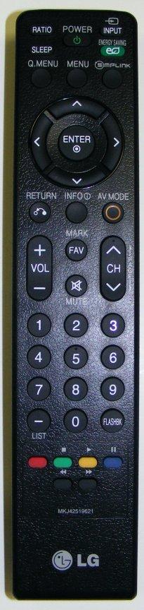

13 Remote Control Familiarization BOTTOM PORTION TOP PORTION 13
 Turn the Set On 2) Simultaneously, Press and Hold the Menu Key on the Side Key pad and Press and")
 If Customer s Menu appears, continue to hold until it disappears.")
14 Accessing the Service Menu SIDE KEYS REMOTE BOTTOM PORTION To access the Service Menu. 1) Turn the Set On 2) Simultaneously, Press and Hold the Menu Key on the Side Key pad and Press and Hold the Menu Key on the Remote approximately 5 seconds. 3) If Customer s Menu appears, continue to hold until it disappears. 4) The Service Menu appears Note: If a Password is required to enter the Service Menu. Enter;


15 Rear and Side Input Jacks Rear In/Out Jacks USB Port Software Upgrades Music, Photos Side In/Out MAIN PWB Rear and Side Input/Output locations Rear Side 15
 With TV turned on, insert USB flash drive.")
 You can see the download progress Bar. 7) Do not unplug until unit has automatically restarted. 8) When download is completed, you will see COMPLETE. 9) Your TV will be restarted automatically.")
16 USB DOWNLOAD 1) Create an LG_DTV folder on the USB Flash Drive Shows the Currently Installed Version 2) Copy new software (xxx.epk) to "LG_DTV" folder. Make sure to have correct software file. 3) With TV turned on, insert USB flash drive. 4) You can see the message TV Software Upgrade (See figure to right) 5) Cursor left and highlight "START" Button and push Enter button using the remote control. 6) You can see the download progress Bar. 7) Do not unplug until unit has automatically restarted. 8) When download is completed, you will see COMPLETE. 9) Your TV will be restarted automatically. Shows the Software Version found on the USB Flash Drive Shows the Software file found on the USB Flash Drive * CAUTION: Do not remove AC power or the USB Flash Drive. Do not turn off Power, during the upgrade process. 16

17 Product Dimensions Wattage Average: 143W Stand By: less than 1W There must be at least 4 ihes of Clearae on all sides 40-13/16" mm 7-7/8" 200mm 3-1/2" 88.9mm 25-13/16" 655.3mm 16-1/8" 410mm 12-15/16" 327.8mm 9-1/16" 230mm 28-3/8" 721.4mm 3-7/8" 97.8mm 20-7/16" 518mm Center 7-7/8" 200mm Model No. Serial No. Label 12-15/16" 327.8mm 8-7/8" 225.3mm Remove 4 screws to remove stand for wall mount 2-9/16" 65.7mm Weight without Stand: 36.4 lb Weight with Stand: 40.3 lb 22-13/16" 580mm /16" 294mm
18 DISASSEMBLY AND TROUBLESHOOTING SECTION Disassembly: This section of the manual will discuss Disassembly, Layout and Circuit Board Identification, of the LCD Direct View Television. Upon completion of this section the Technician will have a better understanding of the disassembly procedures, the layout of the printed circuit boards and be able to identify each board. Troubleshooting: This section of the manual will also discuss troubleshooting. Upon completion of this section the Technician will have a better understanding of how to diagnosis and resolve problems. 18

19 Removing the Back Cover Remove the 21 screws indicated. Pay attention to the size and type of screw as there are many different types. Putting in an improper screw when reassembling may Cause damage. The Stand does not need to be removed before removing the back. 19

20 Circuit Board Layout No T-CON or Ballast board LVDS Cable POWER SUPPLY LVDS Cable Main PWB Side Keys Backlight Connections AC Input Rear Inputs RF Input Master Power Switch Ft IR/LED Control Speaker R Speaker L 20
21 POWER SUPPLY SECTION This switch mode power supply has the ballast section built in. The power supply develops Stand By 5V, 12V and 24V for the Main board. This power supply draws a little less that 1 watt during stand by mode. The fuse F501 reads 157V (from hot ground) during this time. When the controller chip (on the back) receives the PWR-ON command via P201 Pin 19, the primary section ireases its current supplying ability. The Primary fuse F501 now reads V is routed out P201 pins 5 and 6 and 24V is routed out P201 pins 1 and 2. Internally, the power supply also sends B+ (39) voltage to the Ballast section but it is not turned on at this time. When the power supply receives the INV-ON command via P201 pin 20, it is routed to the driver for the ballast (on the back of the board). The driver now starts to deliver drive information to the output FETs (on the far left hand heat sink) which in turn switch the primary sides of the two ballast transformers T703 and T704. They output 1.2Kv (48Khz) pulses to the backlights via P401 and P


22 Power Supply PWB Removal P201 Disconnect P201, P401, P402, AC In SK101 and SK102. P201 Remove the 6 screws indicated by the arrows w/screw. P402 SK101 Press in Two tabs to release lock P401 SK102 AC In 22
. This prevents any activity of the IR or the Key Board.")
23 Power Supply (Main Power Switch Type 1) Location There are three types of Main Power switch used in LG televisions. This set utilizes Type 1. Type 1: Shuts off AC to the Power Supply. Type 2: Opens ground to the front IR board. (Stand-By 5V Remains, the Main board stays alive). This prevents any activity of the IR or the Key Board. When the Switch is opened, a line called Power Key pulls up high when ground opens. When the switch is closed, this same line called Power Key feeds back to the Microprocessor and the Micro. Turns on the Power. Type 3: Opens ground to the front IR board. (Stand-By 5V turns off, the Main board is dead). This prevents any activity of the IR or the Key Board. When the Switch is opened, a line called Power Key pulls up high when ground opens. This line feeds back to the Main board and from there it routes to the Power Supply. The high tells the Controller chip to turn off STBY-5V. When the switch is closed, this same line called Power Key now goes high and feeds back to the Power Supply and tells the controller chip to turn STBY-5V on. If the TV won t come on, be sure to check the Main Power Switch before assuming a failure has occurred. This switch breaks AC to the SMPS. MAIN POWER SWITCH LOCATION TYPE 1 (Bottom Right Side viewed from front) Off On 23
 during this time.")
24 POWER SUPPLY SECTION This switch mode power supply has the ballast section built in. The power supply develops Stand By 5V, 12V and 24V for the Main board. This power supply draws a little less that 1 watt during stand by mode. The fuse F501 reads 157V (from hot ground) during this time. When the controller chip (on the back) receives the PWR-ON command via P201 Pin 19, the primary section ireases its current supplying ability. The Primary fuse F501 now reads V is routed out P201 pins 5 and 6 and 24V is routed out P201 pins 1 and 2. Internally, the power supply also sends B+ (39) voltage to the Ballast section but it is not turned on at this time. When the power supply receives the INV-ON command via P201 pin 20, it is routed to the driver for the ballast (on the back of the board). The driver now starts to deliver drive information to the output FETs (on the far left hand heat sink) which in turn switch the primary sides of the two ballast transformers T703 and T704. They output 1.2Kv (48Khz) pulses to the backlights via P401 and P
25 Power Supply Start Up Sequee Master (Main) Power Sw Off On 1 L L AC In At point 3 TV is in Stand-By state. Energy Star compliant. Less than 1 Watt Power Supply will not be on if Main Power Switch is off. Stand By 5V Reg Stand By 5V In Stand-By Primary side is 178V In Run it is 38 POWER SUPPLY (SMPS) 12V/24V Regulators PWR Inv On V 24V 38 Regulator Inverter On 9 A-DIM Fixed 6 8 P-DIM BALLAST SECTION Drive Sig Inverter On Starts the Ballast Drive Signal P-DIM DC Up, Backlight brightness Up Ballast Driver FETs Manipulates Backlights Cust Menu for Backlight Picture Content 9 Intelligent Sensor feedback 1.2Kv 64K 1.2Kv Backlights Light 10 2 Reg for Micon +5V General Resets Microprocessor Main Board Power Det. Circuit 5 3 Other Regs Other Circuits 5V Reg 5 Relay On (PWR) Microprocessor section of Mstar IC100 12V Video Processing 24V Audio MAIN PWB 8 7 Inv On/Off Other Circuits LVDS Panel Control Video Processing section of Mstar IC100 12V LVDS 12V Video 7 TFT Driver Section Main PWB Tru-Motion 12V LVDS IC Ft Control 4 TFT Controler Section Video Blue LED lights to assist Backlight Lamp Firing Remote or Key Power On 11 To Panel 25
26 P700 on Main Board to SMPS P201 Turn On Circuit Diagram Q706 P201 n/c 1 PWR SBY5V 12V 24V n/c INV.On A.DIM ERR Out n/c PWM-DIM SMPS n/c 4.98V 5V 5V 5V 5V 12V 12V 21.3V 21.3V n/c 3.8V 1.8V n/c 3.38V MAIN PWB P PWM-DIM (PWM Dimming) Manipulates the Backlight Brightness via Customer s OSD. Manipulates the Backlight Brightness via the Video Processor Chip. Darker Picture, Darker Backlights to facilitate improved Contrast Ratio. 0.6V ~ Range LVDS 12V Panel Power n/c n/c L704 +5V L707 C721 68uF L715 +5V General L709 L701 PWR ON C pF INV ON/OFF 5.2V Error Out L728 L706 12V C722 47uF 24V C727 68uF R A-DIM L700 Analog Dimming (Fixed Value) Digital Dimming (Variable) PWM-DIM C uF Stby = 5V Run = Q701 L R V 0.2V Q700 STBY5V R KΩ 10K R702 Q702 C706 1uF C725 1uF R739 47KΩ C uF 0.6V Q703 R Ω R K R760 0 R740 47KΩ Power On +5V General R719 1KΩ Q705 R726 10KΩ R713 0Ω C181 1uF 0.6V STBY5V C182 1uF R K R Q704 R Ω Error 5V: Normal : Lamps try to fire 4 time, if Error line is high, Micro shuts off television. R Ω Relay On E5 GPIO 134 AB12 R732 22KΩ GPIO137 LVDS Panel Control IC100 Mstar G5 GPIO 136 Inverter On/Off AB13 L708 E8 GPIO 97 PWM0 A-DIM P-DIM PWM2 12V R H5
27 TEST 1 Power Supply PWB Low Voltage Test AC Should not be applied at any time while adding resistors or while unplugging connectors as damage to the circuit PWB may occur. a) The SMPS PWB MUST be producing STBY 5V on either pin 7, 8, 9 or 10 (5V). If 5V Standby is not being generated, the SMPS PWB is defective and must be replaced. There is no need to continue with the next test. (b) Unplug P700 on the Main PWB. TEST 1: (1) Add a 100Ω resistor between (5V STBY) pin 7, 8, 9 or 10 and Pin 2 (PWR). Apply AC. This will turn on the power supply. a) Check that the 24V and 12V power supplies are turned on, P201 (24V pins 17 and 18) P201 (12V pins 13 and 14) (2) Remove AC power. 27 Use P700 Side to insert resistors
 Add another 100Ω resistor between (5V) pin 7, 8, 9 or 10 and Pin 20 (INV On). (4) Apply AC Power. Simulating a Power and Backlight On command.")
28 TEST 2 Power Supply PWB Backlights Test P700 Connector disconnected from the Main PWB. Apply AC after adding jumper. Continue if the 1 st test was OK. Leave original resistor in place. (3) Add another 100Ω resistor between (5V) pin 7, 8, 9 or 10 and Pin 20 (INV On). (4) Apply AC Power. Simulating a Power and Backlight On command. Backlights Normal: a) If normal, the backlights should turn on. SMPS OK. Backlights Abnormal: a) Recheck all connections. b) Confirm the INV On/Off line pulling up to at least 3V. REMOVE AC POWER: c) Check the connections to the Backlights. DO NOT check these when AC is applied as they carry 1.2Kv each. Note, either of the connections are unplugged, the backlights will not light. 28 Use P700 Side to insert resistors
 LOW COST Large number of lamps driven")
29 General Backlight Information To Backlights Over 1.2KV Ballast Section of SMPS To Backlights Over 1.2KV Currently, number of lamps Unknown EEFL (External Electrode Fluorescent Lamp) LOW COST Large number of lamps driven by a single inverter 29
30 Introducing EEFL Simple structure, Low price Complicated structure Simple structure Lamp manufacturing process Lamp assembly structure Low Cost Large number of Lamp Drive by single inverter 30
31 Introducing EEFL Contacts (Bulb Design) Key: Long Life Time For CCFL, Hg gas is consumed mainly near the internal electrode For EEFL, longer life time is expected because there is no internal electrode consuming Hg gas 31


32 Ballast Section of SMPS Layout Viewed from rear SMPS PWB Backlights Test Point Bottom of R406 or R403 38V P/P 48Khz To Backlights Left Side T Kv To Backlights Right Side T704 32
33 Ballast Control Signals Circuit Diagram BALLAST SECTION To Backlights 1.2Kv P402 P401 Two Transformers Drive Circuit FETs Q709/10 39 ~13 Drive Control INV On/Off POWER SUPPLY Hot Ballast Power 39 ~13 Varies with PDIM On Back of PWB Stand By 5V Reg 38 Reg 16 Reg IC600 Ballast Control IC On Back of PWB IC301 Controller 12V Reg 24V Reg P P V PWR 4.89V ERR PWM-DIM A-DIM 1.67V STBY5V 12V 24V R Ω INV On/Off R KΩ STBY5V L733 L700 Q702 R Ω R KΩ MAIN PWB R KΩ Q701 R719 1KΩ Q700 R706 +5V General R759 0Ω R703 R Ω R Ω R KΩ R Ω R Ω G5 E5 E8 AB13 AB12 IC100 Mstar INV-On/Off GPIO 136 GPIO 134 RL-ON GPIO 97 ERROR-Out PWM-2 PWB-0 VBR-A (Analog Dimming) This line is not used. VBR-B (PWM Dimming) Manipulates the Backlight Brightness via Customer s OSD. Manipulates the Backlight Brightness via the Video Processor. Darker Picture, Darker Backlights to facilitate improved Contrast Ratio. 0.6V ~ Range 33
34 Power Supply Backlight Drive Signal Effects PWMDIM manipulates the Burst Triangle Oscillator in the ballast drive IC. ADIM also manipulates the Burst Triangle Oscillator But it is not used. Note: Backlights will attempt to fire 4 time. During these attempts, the Error line will change from 5V to. when lamp tries to fire or is lit. 5V when the lamps are not lit. After 4 attempts, if the Error Out line returns to 5V, this tells the Micro to turn the set off. 34
35 Power Supply Connector P201 Voltage and Resistae P201 Odd "SMPS" to P700 "Main PWB" Pin Label 1 A.DIM 24V 12V 5V 5V STBY 5.14V 5.14V Run 1.66V 21.4V 12.3V 5.14V 5.14V Diode Check Open 0.81V 1.2V 2.85V 2.85V P201 Even "SMPS" to P700 "Main PWB" Pin Label 2 PDIM Err Out INV.ON 24V 12V 5V 5V PWR-ON STBY 5.14V 5.14V Run 3.2V 3.8V 21.4V 12.3V 5.14V 5.14V 4.98V Diode Check Open Open 2.25V 0.81V 1.2V 2.85V 2.85V 1.19V 1 ADIM Pin 21 Fixed and not used 2 PDIM Pin 24 can vary according to type of signal being processed and the OSD Backlight setting. 0.6V 0% to 100%. Output from the Video Processor IC100. Diode Mode values taken with all Connectors Removed 35

36 Power Supply Connector SK100 and SK101 Voltage and Resistae Diode Mode values taken with all Connectors Removed SK100 "SMPS" to AC IN Pin 1 2 Label L N STBY 12ac Run Diode Check OL OL AC Voltage Readings Across Pins 1 and 2 for STBY and RUN. SK101 "SMPS" to MASTER POWER SWITCH Pin 1 2 Label n/a n/a STBY 12ac Run Diode Check OL OL AC Voltage Readings for either pin 1 or pin 2 in STBY and RUN with one lead on Neutral of SK100. Bottom Right of SMPS F100 With the Master Power Switch Closed (On) AC flows. When Open (Off) AC open and does not flow. Neutral F A/25 AC IN SK101 Live SK100 36
37 MAIN PWB SECTION The Main PWB also contains the T-CON (TFT Driver) section. This set does not use a normal T-CON board. There are two LVDS cable feeds that go directly to the Panel. These carry the TruMotion 120Hz duel 12 bit LVDS, (video signal) that has already been prepared for the panel drivers. The Main board receives its operational B+ from the Power Supply via P700. STAND-BY STBY 5V pins 7~10 The Main board also develops several B+ sources on the board. LVDS VCC-LCM+, VDD-LCM+16V, VGH+24V VGHM+24V VGL-5V RUN AUDIO 1.8V 12V pins 13 and 14 24V pins 17 and 18. Mstar IC100 (Video) / MICROPROCESSOR 1.2V, 1.26V, 1.8V, and TUNER and VSB CIRCUIT 9V which is used to make 5V TU 5V 1.2V 37
38 Removing the Main PWB Disconnect P700, P1204, P600, P1400 and P1401. Remove any tape holding down any cables. Remove the 6 screws indicated by the arrows. Flip the locking tab upward, pull the LVDS ribbon out. Press in on the top and bottom release tabs to remove P700. P700 P1400 P1401 P1200 P600 NOTE: Be sure to check on top and behind the Video Processor ICs. Look for a piece of Chocolate (Heat Transfer Material). Be sure to transfer to new PWB if present. 38
39 Main PWB Layout IC100 Microprocessor and Video Processor P1400, P1401 to Panel MICRO and VIDEO PROCESSOR IC100 and Tru-Motion IC1100 run Hot. This is normal. To SMPS P700 To SMPS P1401 P1400 IC1100 To Ft Control PWB P1200 P600 To Speakers SW100 Reset IC100 X100 X1100 X1005 LD USB LD1000 Tuner OK when Green Tuner TU
40 Main PWB (Front Side) Component Locations 40
41 Front Side Component Voltages MAIN (FRONT SIDE) SIMICONDUCTORS IC V DDR IC705 / 1.26V IC101 Flash Boot IC103 Reset IC707 5V EXT IC1001 FE Pin Pin Pin Memory Pin Pin 1.8V MEMC Pin [1] n/c [1] 0.8V [1] [1] [1] 0.8V [1] 4.9V [2] 3.2V [2] [2] 3.2V [2] [2] [2] 4.9V [3] 3.2V [3] 5V [3] 2.5V [3] [3] 4.9V [3] [4] n/c [4] 6.12V [4] [4] 6.5V [4] 3.36V [5] n/c [5] 4.99V [5] Q105 Power On [5] 4.84V [5] 1.19V [6] 1.8V [6] 1.3V [6] Pin Delay [6] 1.8V [7] 0.79V [7] 1.3V [7] 3.2V E [7] 1.8V IC1000 Flash Boot [8] [8] 3.19V [8] 3.2V B [8] 4.83V Pin Memory C 1.96V [1] IC704 Reg Q706 5V General IC708 Reg IC V Amp [2] 3.36V Pin Pin LVDS 12V Pin Q106 Reset Pin [3] 3.36V [1] 0.79V [1] 5.1V [1] Pin [1] [4] n/c [2] [2] [2] 0.79V E [2] 1.8V [5] n/c [3] 5V [3] 12V [3] 1.26V B [3] [6] 1.19V [4] 7.7V [4] 0.67V [4] 1.26V C [7] 0.79V [5] 4.9V [5] 12V [5] 1.8V [8] [6] [6] 12V [6] 5V [7] [7] 5V [7] IC1002 5V for Tuner [8] 2.1V [8] 5V [8] 5V Pin [1] 8.9V D1400 LVDS 16V D1401 LVDS (-5V) D1402 LVDS D1204 LED Moving [2] 1.93V Pin Source Pin Source Pin Source Pin Ft LED [3] 5V A 14.7V A (-5V) A A [4] n/c J 2 J (-2.38V) K K 0.14V [5] K 27V K A 41
42 Main PWB (Back View) 42
43 Front Side Component Voltages MAIN (BACK SIDE) SIMICONDUCTORS Q1000 Tuner SIF IC1200 HDMI Q1202 Moving LED Q703 Turns on 5V IC104 EEPROM D1403 LVDS 16V Pin Pin Pin Driver Pin General Q706 Pin Pin Source E 2.4V [1] E 0.1V E [1] A 12.2V C [2] C C [2] K 16.6V B 3. [3] B B 0.62V [3] [4] [4] Q1001 Tuner Video [5] 4.8V IC1003 9V Reg Q704 Turns on [5] 3.25V Pin analog [6] 4.8V Pin for Tuner Pin Q705 [6] 3.25V IC1203 SPDIF Optic E 2.5V [7] 4.8V [1] 12.3V E [7] Pin C [8] 4.8V [2] 8.9V C [8] 3.25V [1] 3.25V B 3.2V [3] B 0.62V [2] 3.24V IC1101 Flash IC1100 LD1100 Driver [3] IC1201 RS232 Pin Q600 Audio Mute Pin [4] 1.6V Pin [1] Pin Q705 Turns on LVDS G 0.29V [5] 3.25V [1] [2] 1V E 0.1V Pin 12V Q706 D 2.9V [2] 5.6V [3] 3.26V C 3.2V E S D1100 LD1100 (Q1100) [3] [4] B C Pin Gate [4] [5] B 0.66V A [5] 5.5V [6] 0.1V Q701 PWR-On to IC107 Power Det K 0.33VV [6] 5.5V [7] 3.26V Pin P700 pin 2 IC105 HDCP EEPROM Pin Reset [7] 5.5V [8] 3.26V E 5.12V Pin [1] 0. [8] C 4.99V [1] [2] [9] IC702 STBY B 3.07V [2] [3] 3.2V D1223 B+ Routing [10] 3.26V Pin Turned on by Q700 [3] 5.05V Pin RGB [11] [1] [4] D102 Audio Mute A 5.1V [12] [2] Q702 INV-On to [5] 5.05V Pin Routing K 4.8V [13] [3] 5.1V Pin P700 pin 20 [6] 5.05V A A [14] 5.6V E [7] 3.25V K 0.1V [15] C 3.8V [8] 3.25V A [16] B 41


44 Main PWB X100, X1100 and X1005 Crystal Check IC100 Microprocessor Crystal 3.2Vp/p 12Mhz X1100 TruMotion IC1100 Crystal Set on. Use bottom leg. 2.4Vp/p 12Mhz Set on or off. Use bottom leg. X100 X1005 Tuner Control IC1005 Crystal MAIN PWB 4.95Vp/p 25Mhz 44 Set on. Use top leg.
 system is locked. Illuminated PLL is normal.")
45 Main PWB LD1000 Fution LD1000 Use LD1000 as a visual aid. This lets you know if the tuner internal PLL (Phase Locked Loop) system is locked. Illuminated PLL is normal. Off is abnormal tuner lock. Main PWB LD1000 Location 45
 19 18 13 9 12 8 4 1")
46 Main PWB Tuner with Shield Off (Pin ID)


47 Main PWB Tuner Video and SIF Output Check USING COLOR BAR SIGNAL INPUT MAIN PWB Tuner Location Pin 19 Video Signal Note: Video Out Signal only when receiving an analog Channel. Pin 16 SIF Signal 2.24Vp/p Pin 12 and Pin 13 Dig IF Signal 450mVp/p 700mVp/p Note: Dig IF Signal only when receiving a Digital Channel. 47

48 Main PWB Tuner Clock and Data Lines Note: SCL and SDA only active during an actual Channel Change. Pin 9 SCL 1V per/div 100uS 5V p/p Pin 8 SDA 1V per/div 100uS 5V p/p 48

49 Main Board LVDS Power Supply Voltage Generation Circuit VCC VGL -5V VGHM 26V 50 VDD 16V
50 Main PWB Connector P700 to Power Supply Voltage and Resistae Odd Pins P700 Main PWB" to P201 SMPS PWB" Even Pins Pin Label STBY Run Diode Check Pin Label STBY Run Diode Check 1 2 PWR-ON 4.98V 1.87V V 5.14V 5.14V 1.1V 8 5V 5.14V 5.14V 1.1V 9 5V 5.14V 5.14V 1.1V 10 5V 5.14V 5.14V 1.1V V 12.3V 2.1V 14 12V 12.3V 2.1V V 21.4V Open 18 24V 21.4V Open Inv.Out 3.8V 1.9V 21 1 A.DIM 1.7V 2V 22 Err Out Open PDIM 3.2V Open 1 ADIM Pin 21 Fixed and not used 2 PDIM Pin 24 can vary according to type of signal being processed, OSD Backlight setting. 0.6V 0% to 100% and the Intelligent Sensor. Output from the Video Processor IC100. Diode Mode values taken with all Connectors Removed 49
51 Main PWB Connector P1400 to the Panel Voltage and Resistae P1400 CONNECTOR "Main" to The Panel" Diode Mode values taken with all Connectors Removed Pin Label Run Diode Test Pin Label Run Diode Test Pin Label Run Diode Test 1 21 POL 1.63V 1.3V 41 LMLV0P 1.2V 0.89V 2 VGL (-5V) 0.925V 22 SOE_L 0.2V 1.45V OPT_N 3.24V 1.3V VGH M VCOM_FB VCOM_L GMA1 GMA2 GMA3 GMA4 GMA5 GMA6 GMA7 GMA9 GOE GSP_R GSC H_CONV GSP_R 26V 7V 7V 14V 16V 14V V 11.2V 10.3V 8.4V 0.6V 0.6V 1.63V Open Open 1.4V V 1.36V V V 1.3V 1.3V Open 1.3V LMLV8N LMLV8P LMLV7N LMLV7P LMLV6N LMLV6P LMLV5N LMLV5P LMCLKN LMCLKP LMLV3N LMLV3P LMLV2N LMLV2P LMLV1N LMLV1P LMLV0N 1.2V 1.23V 1.2V 1.25V 1.22V 1.21V 1.2V 1.2V 1.26V 1.25V 1.23V 1.23V 1.3V 1.2V 1.3V 1.2V 1.28V 1.29V 1.29V 1.29V 1.24V 1.29V 1.3V 0.9V 1.29V 1.29V 1.29V 1.29V 0.89V 1.29V 1.29V 1.29V 1.29V 1.29V GMA10 GMA12 GMA13 GMA14 GMA15 GMA16 GMA17 GMA18 VCC VCC VDD VDD VDD LTD_L 7.9V 6V 5.2V 4V 3V 2.3V 0.3V 2.3V 16V 16V 16V 8.2V 1.4V V V V 1.6V Open 51
52 Main PWB Connector P1401 to the Panel Voltage and Resistae P1401 CONNECTOR "Main" to The Panel" Diode Mode values taken with all Connectors Removed Pin Label Run Diode Test Pin Label Run Diode Test Pin Label Run Diode Test 1 21 H_CONV OV Open 41 RMLV1P 1.25V 1.3V 2 LTD_R 8.9V Open 22 GSP OV 1.3V 42 RMLON V 3 VDD 16.55V POL 1.62V 1.3V 43 RMLOP 1.26V 1.3V VDD VDD VCC VCC GMA1 GMA2 GMA3 GMA4 GMA5 GMA6 GMA7 GMA9 GOE GSP_Rev GSC 16.55V 16.55V 14V 16V 14V 13.4V 12.3V 11.2V 10.4V 8.45V 0.6V 1.6V V 1.6V V 1.36V V V 1.3V 1.3V SOE RMLV8N RMLV8P RMLV7N RMLV7P RMLV6N RMLV6P RMLV5N RMLV5P RMCLKN RMCLKP RMLV3N RMLV3P RMLV2N RMLV2P RMLV1N 0.2V 1.2V 1.25V 1.19V 1.21V 1.2V 1.2V 1.19V 1.25V 1.25V 1.23V 1.21V 1.26V 1.19V 1.26V 1.22V 1.5V 0.89V 1.3V 1.3V 1.3V 1.3V 1.3V 1.3V 1.3V 1.3V 1.3V 1.3V 1.3V 1.3V 1.3V 1.3V OPT_N OPT_P GMA10 GMA12 GMA13 GMA14 GMA15 GMA16 GMA17 GMA18 VCOM_R n/c VGH VGL 3.23V OV 7.93V 6V 5.18V 4.86V 3V 2.3V 1.3V 2.3V 7V n/c 26V (-5V) 1.31V 0.9V 1.4V V 1.4V V 1.4V n/c Open 0.925V 52
53 Main PWB Connector P1204 to (Ft. IR/LED Control) Voltage and ResistaeR P1204 CONNECTOR "MAIN PWB" to P1 "Front IR / LED PWB Assy" Pin Label STBY Run Diode Check 1 SCL 1.14V 2 SDA 1.14V 3 4 Key1 1.08V 5 Key2 1.08V 6 5V ST 5.1V 5.1V 1.13V IR 4.8V 4.8V Open _ST 3.29V 3.29V 0.6V 12 POWER On/Off 3.29V 2.17V Diode Mode values taken with all Connectors Removed 53
54 Main PWB Connector P600 to Speakers Voltage and Resistae P600 CONNECTOR "Main" to "Speakers" Pin LABEL SBY Run Diode Check 1 SPK-R(-) 10.7V 1.5V 2 SPK-R(+) 10.7V 1.5V 3 SPK-L(-) 10.7V 1.5V 4 SPK-L(+) 10.7V 1.5V Use speaker out to test for defective Audio Amp IC600 Diode Mode values taken with all Connectors Removed 54
55 FRONT CONTROL (IR and INTELLIGENT SENSOR) SECTION The Front Control PWB (located on the bottom left as viewed from the rear) contains the IR (Infrared Remote Sensor) and the Intelligent Sensor plus the front Power LEDs. This board also connects with the Side Key PWB. This board receives it operating B+ via pin 6 (STBY 5V) and pin 11 (STBY ) on connector P1. It is received from the Main PWB via the connector P1200. The Intelligent Sensor communicates with the Video Processor IC100 via clock and data lines on the same connector pins 1 and 2. The IR pulses (5V p/p) are sent to the Microprocessor (same IC100) via pin 9. The Key board connector P3000 is routed to the Ft control board via P2. Then through the front Control board and out P2 to the Microprocessor via P1200 pins 4 and 5. Finally, the front Power LEDs are controlled by pin 12 and pin 8. 55

56 FRONT CONTROL BOARD CONNECTIONS IDENTIFIED The below picture shows the connections to the Front Control board. p/n EBR Side Key P3000 P2 P1 Main Power Switch 56
 and the Intelligent Sensor plus the front Power LEDs.")
57 FRONT CONTROL (IR and INTELLIGENT SENSOR) IDENTIFIED The Front Control PWB (located on the bottom left as viewed from the rear) contains the IR (Infrared Remote Sensor) and the Intelligent Sensor plus the front Power LEDs. Light Diffuser Power LEDs Intelligent Sensor Infrared Sensor 57
58 Ft. IR / LED Control Connector P1 and P2 Voltage and Diode Check P1 CONNECTOR "Front IR / LED PWB Assembly " to P1204 " MAIN PWB " Pin Label STBY Run Diode Check 1 SCL Open P2 Connector to Side Key" P SDA Key1 Key2 5V ST 5.1V 5.1V Open Open Open 1.13V Pin Label Key 1 Key 2 STBY Run Diode Check Open Open 8 9 IR 4.8V 4.8V Open _ST 3.29V 3.29V Open 12 POWER On/Off 3.29V Open Diode Mode values taken with all Connectors Removed 58


59 Side Key Assembly SW3001 SW3002 SW3003 SW3004 SW3005 SW3006 SW3007 P3000 SW3008 To Ft Control P
 1.8K Ohms Menu 4.8K Ohms CH (Dn) 4.8K Ohms Enter 10K Ohms CH (Up) 10K Ohms P3000 Voltage Measurements with Key pressed. KEY Pin 1 measured from KEY Pin 3 measured from Power 0.")
60 Side Key Assembly P3000 Voltage and Diode Check P3000 Resistae Measurements with Key pressed. KEY Pin 1 measured from KEY Pin 3 measured from Power Ohms Volume (-) Ohms Input 1.8K Ohms Volume (+) 1.8K Ohms Menu 4.8K Ohms CH (Dn) 4.8K Ohms Enter 10K Ohms CH (Up) 10K Ohms P3000 Voltage Measurements with Key pressed. KEY Pin 1 measured from KEY Pin 3 measured from Power 0.179V Volume (-) 0.179V Input 0.906V Volume (+) 0.906V Menu 1.65V CH (Dn) 1.65V Enter 2.24V CH (Up) 2.24V P3000 P3000 Connector Side Key" to IR/LED Control PWB P1 Pin Label STBY Run Diode Check 1 Key1 Open 2 3 Key2 Open 4 60

61 Invisible Speaker System Overview (Full Range Speakers) The contains the full progression of the Invisible Speaker system. First: The woofer layout is the basic system. The Full Range Speakers point downward, so there is no front viewable speaker grill or air ports. Main Speaker (Full Range Frequeies) Tweeter (High Frequeies) Magnet (Weight) Prevents vibrations Full Range p/n EAB Tweeter p/n EAB


62 Invisible Speaker System Overview (Tweeters) 2 nd : Progression Elimination of the conventional speaker. Invisible Speaker has a sticky surface which adheres to front bezel. The front bezel is shown below. Note: the outlined circle is the location for the front sticky pad on the Invisible Speaker. This prevent the coil from bouing off the plastic causing vibrations. WARNING: Removing the Tweeter will destroy the speaker as shown above. The diaphragm/spider is glued to the front bezel. When removing, it will tear. Tweeter p/n EAB Cabinet works as a diaphragm. Outlined Circle Speaker Attachment post Invisible Speaker Tweeter shown separately. The Front (down) has sticky surface which adheres to front bezel. Note, there is no diaphragm, only voice coil. 62
, only voice coil.")
63 Invisible Speaker System Overview Invisible Speaker Shown separately. Front (to left) has sticky surface which adheres to front bezel. Note, there is no Cone (Diaphragm), only voice coil. Spider Mount Speaker Terminals Speaker Wires Dust Cap with adhesive Magnet Voice Coil Inside Frequey Pass Capacitor Mount 63
64 11 X 17 FOLDOUT SECTION This section shows the 11X17 foldout that s s available in the Paper and Adobe version of the Training Manual. The Adobe version of this Training Manual allows the viewer to zoom in and out making reading of the small text easier. This Power Point shows a graphical representation of the 11 X 17 foldout page so clarity is limited. 64
65 INTERCONNECT DIAGRAM TO TFT MODULE SMPS TEST 1: To Force Power Supply On. Disconnect P700 on Main PWB. Jump pin 7,8,9 or 10 (5V) to pin 2 using a 100Ω resistor. (Test Voltage Outputs 12V, and 24V). SMPS TEST 2: Jump pin 2 to pin 20 (INV-ON). (Backlights and all voltages should turn on). P201 SMPS" to P700 "Main PWB" Pin ,18 15,16 13,14 11,12 7,8,9,10 3,4,5,6 2 1 Label 2 PDIM Err Out 1 A.DIM INV.ON 24V 12V 5V PWR-On 1 ADIM Pin 21 Fixed and not used 2 PDIM Pin 24 can vary according to type of signal being processed and the OSD Backlight setting. 0.6V 0% to 100%. Output from the IC100. R406 / R403 Bottom leg 48Khz 53V p/p STBY 5.14V Run 3.2V 1.66V 3.8V 21.4V 12.3V 5.14V 4.98V Diode Check Open Open Open 2.25V 0.81V 1.2V 2.85V 1.19V P1204 CONNECTOR "MAIN PWB" to J1 "Front IR / LED PWB R406 R KV 1.2KV SMPS Switch Mode Power Supply P402 P401 F A/25 Run 38 STBY 157V From Hot T704 T mF 25 82mF SK mF F A/25 AC IN F V Pin 42 IC1300 For Panel P201 26V Pin 8 IC1300 For Panel 1 2-5V Anode D1401 For Panel 25 82mF SK101 AC IN Tuner Q701 Q702 P700 Q703 P1200 IC706 P600 IC1003 Top Side of L1301 For Panel Q705 Q704 L607 L606 L1301 D1403 L1300 IC704 Q706 IC702 IC1002 D1402 L718 Q1202 IC600 IC601 D1401 D1400 IC1300 L710 IC701 IC1 IC105 IC104 D102 Q600 Q105 Pin 59 (-5V) Pin 57 (26V) IC705 L726 D1204 X Mhz IC103 Micro Reset SW100 Q106 P1401 IC100 Micro and Video Processor Mstar Pin 3,4,5 (16V) Pin 7,8 () IC2 IC502 X Mhz IC101 IC1301 Q100 IC102 IC501 IC1200 D500 Pin 56,57,58 (16V) Pin 53,54 () IC1101 IC1100 Video Processor Tru-Motion IC708 IC1000 Video Reset SW1100 IC1201 D1223 IC1203 P1400 Pin 2 (-5V) Pin 4 (26V) IC301 IC300 L712 Q1100 P1100 Software Upgrades IC707 D1100 N/C IC1001 IC1202 X Mhz LD1100 IC1004 8vsb/ QAM LD1000 TUNER TU1001 Q1001 Video 19 Q1000 SIF 16 (5V) 15 DIF - 13 DIF + 12 Pin Label SCL SDA Key1 Key2 5V ST IR _ST POWER On/Off STBY 5.1V 4.8V 3.29V Run 5.1V 4.8V 3.29V 3.29V Diode Check Open 1.67V 1.4V 1.1V 1.5V Open 0.76V Open Side (Key) Controls P3000 P2 Front PWB Assembly P1 IR Receiver Intelligent Sensor Main Power SW P2 "Front IR / LED PWB to P3000 Keys Pin Label Key1 Key2 STBY Run Diode Check Open Open MAIN (Digital) Board Components that are Grayed out are on the back. Component Voltage on Next Page Q1200 (5V) 4 1
66 MAIN (BACK SIDE) SIMICONDUCTORS Q1000 Tuner SIF IC1200 HDMI Q1202 Moving LED Q703 Turns on 5V IC104 EEPROM D1403 LVDS 16V D1100 LD1100 (Q1100) D1223 B+ Routing Pin Pin Pin Driver Pin General Q706 Pin Pin Source Pin Gate Pin RGB E 2.4V [1] E 0.1V E [1] A 12.2V A A 5.1V C [2] C C [2] K 16.6V K 0.33VV K 4.8V B 3. [3] B B 0.62V [3] A [4] [4] Q1001 Tuner Video [5] 4.8V IC1003 9V Reg Q704 Turns on [5] 3.25V Pin analog [6] 4.8V Pin for Tuner Pin Q705 [6] 3.25V IC1203 SPDIF Optic E 2.5V [7] 4.8V [1] 12.3V E [7] Pin C [8] 4.8V [2] 8.9V C [8] 3.25V [1] 3.25V B 3.2V [3] B 0.62V [2] 3.24V IC1101 Flash IC1100 LD1100 Driver [3] IC1201 RS232 Pin Q600 Audio Mute Pin [4] 1.6V Pin [1] Pin Q705 Turns on LVDS S G G 0.29V [5] 3.25V [1] [2] 1V E 0.1V Pin 12V Q706 D 2.9V [2] 5.6V [3] 3.26V C 3.2V E S D [3] [4] B C [4] [5] B 0.66V [5] 5.5V [6] 0.1V Q701 PWR-On to IC107 Power Det [6] 5.5V [7] 3.26V Pin P700 pin 2 IC105 HDCP EEPROM Pin Reset [7] 5.5V [8] 3.26V E 5.12V Pin [1] 0. C [8] E B C 4.99V [1] [2] [9] IC702 STBY B 3.07V [2] [3] 3.2V [10] 3.26V Pin Turned on by Q700 [3] 5.05V [11] [1] [4] D102 Audio Mute [12] [2] Q702 INV-On to [5] 5.05V Pin Routing [13] [3] 5.1V Pin P700 pin 20 [6] 5.05V A [14] 5.6V E [7] 3.25V K 0.1V [15] C 3.8V [8] 3.25V A [16] B MAIN (FRONT SIDE) SIMICONDUCTORS IC V DDR IC705 / 1.26V IC101 Flash Boot IC103 Reset IC707 5V EXT IC1001 FE Pin Pin Pin Memory Pin Pin 1.8V MEMC Pin [1] n/c [1] 0.8V [1] [1] [1] 0.8V [1] 4.9V [2] 3.2V [2] [2] 3.2V [2] [2] [2] 4.9V [3] 3.2V [3] 5V [3] 2.5V [3] [3] 4.9V [3] [4] n/c [4] 6.12V [4] [4] 6.5V [4] 3.36V [5] n/c [5] 4.99V [5] Q105 Power On [5] 4.84V [5] 1.19V [6] 1.8V [6] 1.3V [6] Pin Delay [6] 1.8V [7] 0.79V [7] 1.3V [7] 3.2V E [7] 1.8V IC1000 Flash Boot [8] [8] 3.19V [8] 3.2V B [8] 4.83V Pin Memory C 1.96V [1] IC704 Reg Q706 5V General IC708 Reg IC V Amp [2] 3.36V Pin Pin LVDS 12V Pin Q106 Reset Pin [3] 3.36V [1] 0.79V [1] 5.1V [1] Pin [1] [4] n/c [2] [2] [2] 0.79V E [2] 1.8V [5] n/c [3] 5V [3] 12V [3] 1.26V B [3] [6] 1.19V [4] 7.7V [4] 0.67V [4] 1.26V C [7] 0.79V [5] 4.9V [5] 12V [5] 1.8V [8] [6] [6] 12V [6] 5V [7] [7] 5V [7] IC1002 5V for Tuner [8] 2.1V [8] 5V [8] 5V Pin [1] 8.9V D1400 LVDS 16V D1401 LVDS (-5V) D1402 LVDS D1204 LED Moving [2] 1.93V Pin Source Pin Source Pin Source Pin Ft LED [3] 5V A 14.7V A K A (-5V) A A [4] n/c J 2 J (-2.38V) K K 0.14V [5] K 27V J K A
67 Direct View LCD This coludes the training session.
42LH20. Direct View LCD
 42LH20 Direct View LCD Original: March 2009 Updated: February 11, 2010 OUTLINE Section 1 Contact Information, Preliminary Matters, Specifications, LCD Overview, General Troubleshooting Steps, Signal Distribution,
USER MANUAL. 27 Full HD Widescreen LED Monitor L27ADS
 USER MANUAL 27 Full HD Widescreen LED Monitor L27ADS TABLE OF CONTENTS 1 Getting Started 2 Control Panel/ Back Panel 3 On Screen Display 4 Technical Specs 5 Care & Maintenance 6 Troubleshooting 7 Safety
USER MANUAL. 22" Class Slim HD Widescreen Monitor L215DS
 USER MANUAL 22" Class Slim HD Widescreen Monitor L215DS TABLE OF CONTENTS 1 Getting Started Package Includes Installation 2 Control Panel / Back Panel Control Panel Back Panel 3 On Screen Display 4 Technical
PLL2210MW LED Monitor
 PLL2210MW LED Monitor USER'S GUIDE www.planar.com Content Operation Instructions...1 Safety Precautions...2 First Setup...3 Front View of the Product...4 Rear View of the Product...5 Quick Installation...6
17 19 PROFESSIONAL LCD COLOUR MONITOR ART
 17 19 PROFESSIONAL LCD COLOUR MONITOR ART. 41657-41659 Via Don Arrigoni, 5 24020 Rovetta S. Lorenzo (Bergamo) http://www.comelit.eu e-mail:export.department@comelit.it WARNING: TO REDUCE THE RISK OF FIRE
LCD VALUE SERIES (32 inches)
") LCD VALUE SERIES (32 inches) http://www.orionimages.com All contents of this document may change without prior notice, and actual product appearance may differ from that depicted herein 1. SAFETY INSTRUCTION
LCD VALUE SERIES (32 inches) http://www.orionimages.com All contents of this document may change without prior notice, and actual product appearance may differ from that depicted herein 1. SAFETY INSTRUCTION
TFT LCD MONITOR USER MANUAL. L80AP and L101AP
 TFT LCD MONITOR USER MANUAL L80AP - 8.0 and L101AP - 10.1 Table Of Contents Table of contents/ Warning.... 2 Precautions...3 About this user manual and products / Items included in the delivery..... 4
USER MANUAL. 27 Full HD Widescreen LED Monitor L270E
 USER MANUAL 27 Full HD Widescreen LED Monitor L270E TABLE OF CONTENTS 1 Getting Started 2 Control Panel/ Back Panel 3 On Screen Display 4 Technical Specs 5 Care & Maintenance 6 Troubleshooting 7 Safety
USER MANUAL Full HD Widescreen LED Monitor L215IPS
 USER MANUAL 21.5 Full HD Widescreen LED Monitor L215IPS TABLE OF CONTENTS 1 Getting Started 2 Control Panel/ Back Panel 3 On Screen Display 4 Technical Specs 5 Care & Maintenance 6 Troubleshooting 7 Safety
PL2410W LCD Monitor USER'S GUIDE.
 PL2410W LCD Monitor USER'S GUIDE www.planar.com Content Operation Instructions...1 Safety Precautions...2 First Setup...3 Front View of the Product...4 Rear View of the Product...5 Quick Installation...6
USER MANUAL Full HD Widescreen LED Monitor L215ADS
 USER MANUAL 21.5 Full HD Widescreen LED Monitor L215ADS TABLE OF CONTENTS 1 Getting Started 2 Control Panel/ Back Panel 3 On Screen Display 4 Technical Specs 5 Care & Maintenance 6 Troubleshooting 7 Safety
Evolution Digital HD Set-Top Box Important Safety Instructions
 Evolution Digital HD Set-Top Box Important Safety Instructions 1. Read these instructions. 2. Keep these instructions. 3. Heed all warnings. 4. Follow all instructions. 5. Do not use this apparatus near
PXL2760MW LED LCD Monitor
 PXL2760MW LED LCD Monitor USER'S GUIDE www.planar.com Content Operation Instructions...1 Safety Precautions...2 Package Overview...3 First Setup...4 Front View of the Product...5 Rear View of the Product...6
22" Touchscreen LED Monitor USER'S GUIDE
 22" Touchscreen LED Monitor USER'S GUIDE Content Operation Instructions...1 Unpacking Instructions...2 Safety Precautions...2 Front View of the Product...3 Rear View of the Product...4 Quick Installation...5
USER MANUAL Full HD Widescreen LED Monitor L236VA
 USER MANUAL 23.6 Full HD Widescreen LED Monitor L236VA TABLE OF CONTENTS 1 Getting Started 2 Control Panel/ Back Panel 3 On Screen Display 4 Technical Specs 5 Care & Maintenance 6 Troubleshooting 7 Safety
USER MANUAL. 28" 4K Ultra HD Monitor L28TN4K
 USER MANUAL 28" 4K Ultra HD Monitor L28TN4K TABLE OF CONTENTS 1 Getting Started 2 Control Panel/ Back Panel 3 On Screen Display 4 Technical Specs 5 Care & Maintenance 6 Troubleshooting 7 Safety Info &
600 Series Video Surveillance Monitors
 600 Series Video Surveillance Monitors 32 LED Monitor 43, 50, 55 & 55 4K LED Monitor Models: PMCL632: PMCL643 PMCL650 PMCL655 PMCL655K Contents for Wall Mount Monitor User Manual (10/16)... 1 Important
PLL1920M LED LCD Monitor
 PLL1920M LED LCD Monitor USER'S GUIDE www.planar.com Content Operation Instructions...1 Safety Precautions...2 First Setup...3 Front View of the Product...4 Rear View of the Product...5 Installation...6
OWNER S MANUAL MOTORIZED 7 WIDE TFT LCD COLOR MONITOR CNT-701
 OWNER S MANUAL PW MOTORIZED 7 WIDE TFT LCD COLOR MONITOR CNT-701 ANY CHANGES OR MODIFICATIONS IN CONSTRUCTION OF THIS UNIT DEVICE WHICH IS NOT APPROVED BY THE PARTY RESPONSIBLE FOR COMPLIACE COULD VOID
PLL2710W LED LCD Monitor
 PLL2710W LED LCD Monitor USER'S GUIDE www.planar.com Content Operation Instructions...1 Safety Precautions...2 Package Overview...3 First Setup...4 Front View of the Product...5 Rear View of the Product...6
User Manual MODEL: KKF1500-PCAP. True FLAT P-CAP LCD Monitor. Installation Guide. 15 True FLAT P-CAP Touch LCD Monitor
 True FLAT P-CAP LCD Monitor User Manual Installation Guide 15 True FLAT P-CAP Touch LCD Monitor MODEL: KKF1500-PCAP i-tech Company LLC TOLL FREE: (888) 483-2418 EMAIL: info@itechlcd.com WEB: www.itechlcd.com
PXL2470MW LED LCD Monitor
 PXL2470MW LED LCD Monitor USER'S GUIDE www.planar.com Content Operation Instructions...1 Unpacking Instructions...2 Safety Precautions...2 Package Overview...3 First Setup...4 Front View of the Product...5
TFT-LCD Color Monitor FS-L4201C
 User Manual English TFT-LCD Color Monitor FS-L4201C www.tandberg.net Printed in Korea Part No. 942667020001-01 INFORMATION TO USER : This equipment has been tested and found to comply with the limits of
VMA ACTIVE MATRIX TFT COLOR LCD MONITOR OWNER S MANUAL INSTALLATION GUIDE
 VMA6491 6.4 ACTIVE MATRIX TFT COLOR LCD MONITOR OWNER S MANUAL INSTALLATION GUIDE OWNER S MANUAL WARNING! THE CLARION VMA6491 LCD MONITOR IS DESIGNED FOR REAR SEAT PASSENGER VIEWING ONLY. THIS PRODUCT
apple Service Source Apple Cinema HD Display 23" LCD (ADC) 11 April Apple Computer, Inc. All rights reserved.
 11 April Apple Computer, Inc. All rights reserved.") apple Service Source Apple Cinema HD Display 23" LCD (ADC) 11 April 2003 2003 Apple Computer, Inc. All rights reserved. apple Service Source Take Apart Apple Cinema HD Display 23" LCD (ADC) 2003 Apple
apple Service Source Apple Cinema HD Display 23" LCD (ADC) 11 April 2003 2003 Apple Computer, Inc. All rights reserved. apple Service Source Take Apart Apple Cinema HD Display 23" LCD (ADC) 2003 Apple
Noise Detector ND-1 Operating Manual
 Noise Detector ND-1 Operating Manual SPECTRADYNAMICS, INC 1849 Cherry St. Unit 2 Louisville, CO 80027 Phone: (303) 665-1852 Fax: (303) 604-6088 Table of Contents ND-1 Description...... 3 Safety and Preparation
Instruction Guide. The TV Jockey Computer Monitor TV Tuner with Remote COMP2VGATVGB. The Professionals Source For Hard-to-Find Computer Parts
 VIDEO ADAPTER The TV Jockey Computer Monitor TV Tuner with Remote COMP2VGATVGB Instruction Guide * Actual product may vary from photo The Professionals Source For Hard-to-Find Computer Parts FCC COMPLIANCE
User Manual MODEL: KK1500-TR. Touch Display LCD Monitor. Installation Guide. 15 Resistive Touch LCD Monitor
 Touch Display LCD Monitor User Manual Installation Guide 15 Resistive Touch LCD Monitor MODEL: KK1500-TR i-tech Company LLC TOLL FREE: (888) 483-2418 EMAIL: info@itechlcd.com WEB: www.itechlcd.com User
Marshall Electronics. Pro A/V Communications VMV-402-SH. 3G/HD/SD-SDI Quad-viewer/Switcher with Audio Meter Display. User Manual.
 Marshall Electronics Pro A/V Communications VMV-402-SH 3G/HD/SD-SDI Quad-viewer/Switcher with Audio Meter Display User Manual Table of Contents 1. Introduction... 3 2. Features... 3 3. Package Contents...
P XGA TFT Monitor. User s Manual
 P6151 15 XGA TFT Monitor User s Manual Disclaimers This manual has been carefully checked and believed to contain accurate information. Axiomtek Co., Ltd. assumes no responsibility for any infringements
USER MANUAL. 27" 2K QHD LED Monitor L27HAS2K
 USER MANUAL 27" 2K QHD LED Monitor L27HAS2K TABLE OF CONTENTS 1 Getting Started 2 Control Panel/ Back Panel 3 On Screen Display 4 Technical Specs 5 Troubleshooting 6 Safety Info & FCC warning 1 GETTING
apple Service Source Apple Studio Display 17" LCD (ADC) Updated 6 Decenber Apple Computer, Inc. All rights reserved.
 Updated 6 Decenber Apple Computer, Inc. All rights reserved.") apple Service Source Apple Studio Display 17" LCD (ADC) Updated 6 Decenber 2004 2003 Apple Computer, Inc. All rights reserved. apple Service Source Take Apart Apple Studio Display 17" LCD (ADC) 2003 Apple
apple Service Source Apple Studio Display 17" LCD (ADC) Updated 6 Decenber 2004 2003 Apple Computer, Inc. All rights reserved. apple Service Source Take Apart Apple Studio Display 17" LCD (ADC) 2003 Apple
19 / 20.1 / 22 WIDE SCREEN TFT-LCD MONITOR
 19 / 20.1 / 22 WIDE SCREEN TFT-LCD MONITOR V193/ V220 Series V202 Series USER MANUAL www.viewera.com Rev. 2.0 Table of Contents EMC Compliance......1 Important Precautions...2 1. Package contents....3
Uni700 LCD Controller
 Landmark Technology Inc. Uni700 LCD Controller For TFT LCDs with Resolution up to 1,920 x 1,200 (Version A) January 27, 2009 1 1. Introduction The Uni700 controller board is designed for LCD panels of
17" & 19" Color TFT LCD Monitor
 17" & 19" Color TFT LCD Monitor KMC-17B & KMC-19B User's Manual for Operation and installation Screen Size : KMC-17B (17" inch TFT LCD) KMC-19B (19" inch TFT LCD) Display Size : KMC-17B (337.920mm X 270.336mm)
LX600 LCD TV Technical Information
 LX600 LCD TV Technical Information TC-32LX600 Outline Features Overall Block Diagram A Board Main Layout Power On Sequence Protection Shutdown Troubleshooting Adjustments 1 Features Model TC-LX60 TC-LX600
CAUTION RISK OF ELECTRIC SHOCK NO NOT OPEN
 Evolution Digital HD Set-Top Box Important Safety Instructions 1. Read these instructions. 2. Keep these instructions. 3. Heed all warnings. 4. Follow all instructions. 5. Do not use this apparatus near
HD Digital Set-Top Box Quick Start Guide
 HD Digital Set-Top Box Quick Start Guide Eagle Communications HD Digital Set-Top Box Important Safety Instructions WARNING TO REDUCE THE RISK OF FIRE OR ELECTRIC SHOCK, DO NOT EXPOSE THIS PRODUCT TO RAIN
Safety Information. Camera System. If you back up while looking only at the monitor, you may cause damage or injury. Always back up slowly.
 Table of Contents Introduction...3 Safety Information...4-6 Before Beginning Installation...7 Installation Guide...8 Wiring Camera & Monitor...9-10 Replacement Installation Diagram...11 Clip-On Installation
Operating Instructions
 Operating Instructions LCDRV700 Digital LCD Color Monitor Please read this manual thoroughly before operating the unit, and keep it for future reference. V1.0 Contents 1. Precautions 2. Features 1 3 3.
NewScope-7A Operating Manual
 2016 SIMMCONN Labs, LLC All rights reserved NewScope-7A Operating Manual Preliminary May 13, 2017 NewScope-7A Operating Manual 1 Introduction... 3 1.1 Kit compatibility... 3 2 Initial Inspection... 3 3
Quick Reference Guide
 Multimedia Projector Quick Reference Guide MODEL 103-011100-01 Projection lens is optional. English Use this book as a reference guide when setting up the projector. For detailed information about installation,
It will cause malfunction if the monitor is operating with unspecified power supply
 User Manual / Installation Guide Model No. PTM-1525R/RT Warning! It will cause malfunction if the monitor is operating with unspecified power supply unit or incorrect power voltage. Do not exposure this
AUTO - SCANNING WITH DIGITAL CONTROL LCD COLOR MONITOR FS-L1903C. User manual (Rev.01) SMITHS HEIMANN
 SMITHS HEIMANN") AUTO - SCANNING WITH DIGITAL CONTROL LCD COLOR MONITOR FS-L1903C User manual (Rev.01) SMITHS HEIMANN www.smithsdetection.com Table of Contents Safety Instructions... 5 Accessories... 8 Power Connections...
AUTO - SCANNING WITH DIGITAL CONTROL LCD COLOR MONITOR FS-L1903C User manual (Rev.01) SMITHS HEIMANN www.smithsdetection.com Table of Contents Safety Instructions... 5 Accessories... 8 Power Connections...
LM/TM-30xx, 31xx Series LCD Monitor User s Manual Rev. A0
 LM/TM-30xx, 31xx Series LCD Monitor User s Manual Rev. A0 FCC NOTICE This equipment generates, uses, and can radiate radio frequency energy and, if not installed and used in accordance with the instructions
INFORMATION TO THE USER
 U.S.FEDERAL COMMUNICATIONS COMMISSION RADIO FREQUENCY INTERFERENCE STATEMENT INFORMATION TO THE USER NOTE: This equipment has been tested and found to comply with the limits for a Class B digital device
HD Digital MPEG2 Encoder / QAM Modulator
 HD Digital MPEG2 Encoder / QAM Modulator HDMI In QAM Out series Get Going Guide ZvPro 800 Series is a one or two-channel unencrypted HDMI-to-QAM MPEG 2 Encoder / QAM Modulator, all in a compact package
MONOPRICE. 27" WQHD Monitor. User's Manual P/N 24659
 MONOPRICE 27" WQHD Monitor P/N 24659 User's Manual CONTENTS SAFETY WARNINGS AND GUIDELINES... 3 FEATURES... 4 CUSTOMER SERVICE... 4 PACKAGE CONTENTS... 4 PRODUCT OVERVIEW... 5 Front... 5 Rear... 5 Rear
TFT LCD MONITOR USER MANUAL HMDE Series 104AV-HMDE 121AV-HMDE 151/152AV-HMDE 156AV-HMDE, 171/172AV-HMDE 185AV-HMDE 191/192AV-HMDE 215AV-HMDE
 TFT LCD MONITOR USER MANUAL HMDE Series 104AV-HMDE 121AV-HMDE 151/152AV-HMDE 156AV-HMDE, 171/172AV-HMDE 185AV-HMDE 191/192AV-HMDE 215AV-HMDE 220AV-HMDE 236AV-HMDE 240AV-HMDE 270AV-HMDE 320AV-HMDE 420AV-HMDE
User Manual TL-2X1-HDVC 2x1 HDMI & VGA Switcher with Control All Rights Reserved Version: TL-2X1-HDVC_160630
 User Manual TL-2X1-HDVC 2x1 HDMI & VGA Switcher with Control All Rights Reserved Version: TL-2X1-HDVC_160630 Preface Read this user manual carefully before using this product. Pictures shown in this manual
V25 V25+ WS WS WS WS V27 WS-65517
 2005 Down to1 HIGH SPEED TROUBLESHOOTING V25-V27 CHASSIS V25 V25+ WS-48515 WS-55615 WS-55515 WS-65615 WS-65515 WS-73615 V25++ WS-55815 WS-65815 WS-55517 V27 WS-65517 WS-73517 MITSUBISHI DIGITAL ELECTRONICS
Content. General information. Main features. For your safety. Unpacking RCU. Front Panel. Real Panel. System wizard and activation.
 User manual This device complies with Part 15 of the FCC Rules. Operation is subject to the following two conditions: (1) this device may not cause harmful interference, and (2) this device must accept
HL32D2A. HL32D2A Page 1 of 13
 This document provide two levels of support; customer advice provides information that meant to be shared with the customer explaining possible operation issues that may be creating problems. Service assistance
In-Ceiling Electric Motorized Front Projection Screen Evanesce Series. User s Guide
 In-Ceiling Electric Motorized Front Projection Screen Evanesce Series User s Guide Important Safety & Warning Precautions Make sure to read this user s guide and follow the procedures below. Caution: The
PRO-ScalerHD2V HDMI to VGA & Audio Scaler Converter. User s Guide. Made in Taiwan
 PRO-ScalerHD2V HDMI to VGA & Audio Scaler Converter User s Guide Made in Taiwan Congratulations for owning a gofanco product. Our products aim to meet all your connectivity needs wherever you go. Have
SAFETY WARNINGS AND GUIDELINES
 SAFETY WARNINGS AND GUIDELINES Please read this manual thoroughly, paying extra attention to these safety warnings and guidelines: Do not expose this monitor to water or moisture of any kind. Do not handle
MONOPRICE. Blackbird 4K Pro HDBaseT Extender Kit. User's Manual P/N 21609
 MONOPRICE Blackbird 4K Pro HDBaseT Extender Kit P/N 21609 User's Manual SAFETY WARNINGS AND GUIDELINES Please read this entire manual before using this device, paying extra attention to these safety warnings
IPSTB1200 /IPC3200 Media Client User guide
 IPSTB1200 /IPC3200 Media Client User guide Safety/Compliance Important Safety Instructions Please carefully read these safety and compliance instructions and this entire user guide. Follow all instructions
User s Guide. 5.8GHz Wireless A/V Signal Sender
 1500332 User s Guide 5.8GHz Wireless A/V Signal Sender Thank you for purchasing your A/V Signal Sender from RadioShack. Please read this user s guide before installing, setting up, and using your new sender.
Electric Wall/Ceiling Projection Screen Saker Series User s Guide
 Electric Wall/Ceiling Projection Screen Saker Series User s Guide Important Safety & Warning Precautions Make sure to read this user s guide and follow the procedures below. Caution: The screen s Black
Quick Start Guide. Wireless TV Connection with Dongle. GWHDKITD PART NO. Q1504-b
 Quick Start Guide Wireless TV Connection with Dongle GWHDKITD PART NO. Q1504-b www.iogear.com Package Contents 1 x GWHDKITD Transmitter 1 x GWHDKITD Receiver 1 x 3 feet HDMI Cable 1 x HDMI Extender Cable
Operating Instructions
 Operating Instructions Digital LCD Color Monitor Please read this manual thoroughly before operating the unit, and keep it for future reference. V1.0 Contents 1. Precautions 2. Features 3. Technical Specifications
PRO-ScalerV2HD VGA to HDMI & Audio Scaler Converter. User s Guide. Made in Taiwan
 VGA to HDMI & Audio Scaler Converter User s Guide Made in Taiwan Congratulations for owning a gofanco product. Our products aim to meet all your connectivity needs wherever you go. Have fun with our products!
Overview U658CV-UMR. Display
 U658CV-UMR Overview With 4K UHD, 8 million pixels illuminate an extraordinary depth and range in every image on this 65" screen. Sceptre 4K Ultra High-Definition displays have 4 times the number of pixels
CP-830FP Chassis TX-29E50D TX-29E50D/B TX-29PS12D TX-29PS12F TX-29PS12P SPECIFICATIONS. Order No: PCZ C2
 Order No: PCZ0510103C2 SPECIFICATIONS Power Source: Power Consumption: 220-240V a.c.,50hz 100W Stand-by Power Consumption: 1,5W Aerial Impedance: 75Ω unbalanced, Coaxial Type Receiving System: PAL-I, B/G,
Electric Wall/Ceiling Projection Screen Saker Tab-Tension Series User s Guide
 Electric Wall/Ceiling Projection Screen Saker Tab-Tension Series User s Guide Important Safety & Warning Precautions Make sure to read this user s guide and follow the procedures below. Caution: The screen
2.4 GHz WIRELESS VIDEO SENDER SYSTEM MODEL: VS6234
 2.4 GHz WIRELESS VIDEO SENDER SYSTEM MODEL: VS6234 Please read this manual thoroughly before operating this system OPERATING INSTRUCTIONS 03/02 1 SAFETY INSTRUCTIONS CAUTION! RISK OF ELECTRIC SHOCK. DO
DCL9AW. User Manual. English
 DCL9AW User Manual English PRECAUTIONS Information for users applicable in European Union countries 1 Information for users applicable in United States of America 1 Installation 1 Power connection 1 Maintenance
MASTR II BASE STATION 12/24V POWER SUPPLY 19A149979P1-120 VOLT/60 Hz 19A149979P2-230 VOLT/50 Hz
 Mobile Communications MASTR II BASE STATION 12/24V POWER SUPPLY 19A149979P1-120 VOLT/60 Hz 19A149979P2-230 VOLT/50 Hz CAUTION THESE SERVICING INSTRUCTIONS ARE FOR USE BY QUALI- FIED PERSONNEL ONLY. TO
SKYPLAY-MX Installation and Operation Guide
 SKYPLAY-MX Installation and Operation Guide Rev 130412 Important Safety Instructions Please completely read and verify you understand all instructions in this manual before operating this equipment. Keep
Model Extend HDMI audio and video connections up to 300 feet. Add up to 8 additional receivers with a dedicated network switch
 HDMI Extender over Single CAT 6 Cable with IR Control Model 103002 Extend HDMI audio and video connections up to 300 feet Utilize existing Cat 6 wiring for an easy installation Add up to 8 additional receivers
Automotive 72 Exterior Smart Lighting Kit
 PACKAGE CONTENTS Automotive 72 Exterior Smart Lighting Kit 36 36 8 x Wire Mounting Bracket 16 x Screws 60" Extension Cable 24 ON / OFF 60 Exterior Kit can also function as interior lighting Instruction
HD Digital MPEG2 Encoder / QAM Modulator
 HD Digital MPEG2 Encoder / QAM Modulator YPrPb VGA In QAM Out series Get Going Guide ZvPro 600 Series is a one or two-channel Component or VGA-to-QAM MPEG 2 Encoder/ Modulator, all in a compact package
2002 DP-2X Chassis Projection Television Information INSTRUCTOR Alvie Rodgers C.E.T. (Chamblee, GA.)
") Dec 00 (ver g) Training Materials Prepared by: ALVIE RODGERS C.E.T. 00 and 00 MODEL RELEASE DIGITAL HD READY PTV Chassis Model # Aspect DP-7 5SWX0B 6X9 57SWX0B 65SWX0B DP-7D DP-6 DP- DP-G 57TWX0B 6X9 65TWX0B
Dec 00 (ver g) Training Materials Prepared by: ALVIE RODGERS C.E.T. 00 and 00 MODEL RELEASE DIGITAL HD READY PTV Chassis Model # Aspect DP-7 5SWX0B 6X9 57SWX0B 65SWX0B DP-7D DP-6 DP- DP-G 57TWX0B 6X9 65TWX0B
Overview U758CV-UMR. Display
 U758CV-UMR Overview At 75", you will feel surrounded by 8 million pixels that are brought to life by unsurpassed clarity and color. Sceptre 4K Ultra High-Definition displays have 4 times the number of
User Manual TL-2X1-HDV 2x1 HDMI & VGA Switcher All Rights Reserved Version: TL-2X1-HDV_160630
 User Manual TL-2X1-HDV 2x1 HDMI & VGA Switcher All Rights Reserved Version: TL-2X1-HDV_160630 Preface Read this user manual carefully before using this product. Pictures shown in this manual are for reference
Overview U650CV-UMS. Display
 U650CV-UMS Overview 4K UHD delivers 8 million pixels that immerse you in an unrivaled landscape of lifelike images. Sceptre 4K Ultra High-Definition displays have 4 times the number of pixels as a Full
User s Manual. 4X1 HDMI Switcher Part #: DL-HDS41
 User s Manual 4X1 HDMI Switcher Part #: DL-HDS41 Congratulations on your purchase of a DigitaLinx Switch. This manual contains information that will assist you in the installation and operation of this
Rain+Birdt. Landscape Irrigation & Maintenance Remote System. Quick Start Guide 4.00 F G H K 9X. c n. System Components
 Rain+Birdt Landscape Irrigation & Maintenance Remote System Quick Start Guide 4.00 D System Components A Transmitter (TX) B Receiver (RX) C Quick Connect (QC) 6-Pin Quick Connect (QC) for use with ESP-Modular
Electric Motorized Projection Screen PowerMax Tension Series
 Electric Motorized Projection Screen PowerMax Tension Series User s Guide Important Safety & Warning Precautions Make sure to read this user s guide and follow the procedures below. Caution: The screen
 Register your product and get support at www.philips.com/welcome SWS3435S/27 SWS3435H/37 EN User manual Contents 1 Important 4 Safety 4 English 2 Your SWS3435 6 Overview 6 3 Installation 7 Connect the
3G/HD/SD-SDI to HDMI Converter
 3G/HD/SD-SDI to HDMI Converter Model #: 3G/HD/SD-SDI to HDMI Converter 2010 Avenview Inc. All rights reserved. The contents of this document are provided in connection with Avenview Inc. ( Avenview ) products.
SK2002DA SIDEKICKER 1-IN, 2-OUT VGA-UXGA DISTRIBUTION AMPLIFIER CABLE USER S GUIDE DISTRIBUTION AMPLIFIERS
 MANUAL PART NUMBER: 400-0152-001 PRODUCT REVISION: 0 SK2002DA SIDEKICKER 1-IN, 2-OUT VGA-UXGA DISTRIBUTION AMPLIFIER CABLE USER S GUIDE TABLE OF CONTENTS Page PRECAUTIONS / SAFETY WARNINGS...2 GENERAL...2
Overview U550CV-UMR. Display
 U550CV-UMR Overview Journey into an incredibly realistic landscape as 8 million pixels of brilliant color and clarity materialize before your eyes. Sceptre 4K Ultra High-Definition displays have 4 times
Overview U405CV-UMS. Display
 U405CV-UMS Overview Journey into an incredibly realistic landscape as 8 million pixels of brilliant color and clarity materialize before your eyes. Sceptre 4K Ultra High-Definition displays have 4 times
CP1 OAD. Owner s Manual. Stereo Control Preamplifier. Ultrafidelity
 OAD Ultrafidelity CP1 Stereo Control Preamplifier Owner s Manual Contents Section Page No. Introduction........................................................................ 1 Warnings.................................................................................
SBL Series Wireless Clock Installation Manual (V2) Table of Contents
 Table of Contents") MOUNTING Table of Contents Wall Mount Installation... Page 2 Double Mount Installation...... Page 3-4 WIRING AND JUMPERS Wiring Information and Jumper Settings... Page 5 FREQUENTLY ASKED QUESTIONS SBL
MOUNTING Table of Contents Wall Mount Installation... Page 2 Double Mount Installation...... Page 3-4 WIRING AND JUMPERS Wiring Information and Jumper Settings... Page 5 FREQUENTLY ASKED QUESTIONS SBL
Model 5240 Digital to Analog Key Converter Data Pack
 Model 5240 Digital to Analog Key Converter Data Pack E NSEMBLE D E S I G N S Revision 2.1 SW v2.0 This data pack provides detailed installation, configuration and operation information for the 5240 Digital
Warranty Information
 Accuform Signs does not handle the warranty for the Digital Signage Displays. Please read below for details on the warranty of your product. If you are having trouble and need assistance, please contact
USERS GUIDE MCX-HTS. HDMI to 3G SDI Converter. Manual Number:
 USERS GUIDE MCX-HTS HDMI to 3G SDI Converter i Manual Number: 151226 SAFETY INSTRUCTIONS Please review the following safety precautions. If this is the first time using this model, then read this manual
User Manual PS-684. HDBaseT Extender Kit 70m. All Rights Reserved. Version: UHBT70P_2016V1.2
 User Manual PS-684 All Rights Reserved Version: UHBT70P_2016V1.2 Preface Read this user manual carefully before using this product. Pictures shown in this manual is for reference only, different model
Overview U550CV-UMS. Display
 U550CV-UMS Overview Journey into an incredibly realistic landscape as 8 million pixels of brilliant color and clarity materialize before your eyes. Sceptre 4K Ultra High-Definition displays have 4 times
Overview U438CV-UMC. Display
 U438CV-UMC Overview Take in the scenery as 8 million pixels illuminate a world of endless color and stunning detail. Sceptre 4K Ultra High-Definition displays have 4 times the number of pixels as a Full
Model 6010 Four Channel 20-Bit Audio ADC Data Pack
 Model 6010 Four Channel 20-Bit Audio ADC Data Pack Revision 3.1 SW v1.0.0 This data pack provides detailed installation, configuration and operation information for the Model 6010 Four Channel 20-bit Audio
MONOPRICE. Blackbird 4K HDBaseT Extender Kit. User's Manual P/N 21792
 MONOPRICE Blackbird 4K HDBaseT Extender Kit P/N 21792 User's Manual SAFETY WARNINGS AND GUIDELINES Please read this entire manual before using this device, paying extra attention to these safety warnings
HTE Owner s Manual. HDMI, RS-232, IR & Ethernet Extender over HDBaseT with 3D, 4K, POE Support
 HTE Owner s Manual HDMI, RS-232, IR & Ethernet Extender over HDBaseT with 3D, 4K, POE Support HTE Tx HTE Rx PureLink TM 535 East Crescent Ave Ramsey, NJ 07446 Tel: 201.488.3232 Fax: 201.621.6118 Website
User Manual TL-TP70-HDIR 70m Extender with ARC and IR All Rights Reserved Version: TL-TP70-HDIR_180723
 User Manual TL-TP70-HDIR 70m Extender with ARC and IR All Rights Reserved Version: TL-TP70-HDIR_180723 Preface Read this user manual carefully before using this product. Pictures shown in this manual is
H270 LED MONITOR USER MANUAL
 H270 LED MONITOR USER MANUAL In order to continue serving our customers and providing the best products, our product information including our user manuals may receive updates from time to time. Please
Jinyoung Contech Co., Ltd.
 TO : Jinyoung Contech Co., Ltd. #501, 222-12 MARIOTOWER, GURO-DONG, GURO-KU, SEOUL, KOREA TEL : 82-2-890-6400 FAX : 82-2-890-6406 HOME PAGE : http://www.jyct.com/ Issued Date : 2006-12-15 Page : 13ages
4, 8, 16 Port VGA/ Audio Extender / Splitter With Local Output with SPDIF Model #: VGA-C5SP-8
 4, 8, 16 Port VGA/ Audio Extender / Splitter With Local Output with SPDIF Model #: VGA-C5SP-8 2010 Avenview Inc. All rights reserved. The contents of this document are provided in connection with Avenview