Hand Carry Studio (ITC-50+DAC-200+TLM-702+SE-500)
|
|
|
- Conrad Phelps
- 5 years ago
- Views:
Transcription
1 Hand Carry Studio (ITC-50+DAC-200+TLM-702+SE-500) HS-550
2 Table of Contents Warnings and Precautions... 3 Warranty... 4 Standard Warranty... 4 Two Year Warranty... 4 Disposal... 4 Packing List... 4 Introduction... 5 Features... 5 Overview HS HS-550 Front Panel... 6 HS-550 Rear Panel... 9 Monitors Quad Preview and Program Completing a manual transition Dissolving or Fading between sources Cutting between sources Wiping between sources List of Wipe transitions and parameters (suitable for photocopying) Effects Using Effects Effects: Quad Effects: Split Effects: Picture in Picture Effects: Freeze Border Background Connecting a computer to the HS Rear input options Channel HS-550 Channel 4 configuration buttons Computer Display Set Up Recording from the HS-550 with an optional DN HS-550 DV port Set Up DN-60 - A brief Set Up guide DN-60 Connections & Controls Front Panel Rear Panel CF Card Slot DN-60 Powering On DN-60 Status LED and Error Messages
3 DN-60 Menu Navigation CF Card Set the Signal Type Set the File Type Set the File System as FAT32 or NTFS Set the Record Date (optional) Starting the Recording Select an empty Bin Recording End recording Prepare the files for editing HS-550 Audio Inputs, Levels, and Meters Audio Monitoring Audio Input Level Calibration Procedure Menu - Color Processor Reset SE-500 Specifications ITC-50 Intercom Controls ITC-100SL Slave Unit Cable Assignments Headset, Jack plug and 5pin XLR ITC-100 XLR cable / 5pin XLR Connector on ITC-100SL ITC-100SL Belt pack 3.5mm Jack socket Headset connector TLM Functions - Front Panel Functions - Rear Panel TLM-702 Specifications Service & Support Disclaimer of Product and Services The information offered in this instruction manual is intended as a guide only. At all times, Datavideo Technologies will try to give correct, complete and suitable information. However, Datavideo Technologies cannot exclude that some information in this manual, from time to time, may not be correct or may be incomplete. This manual may contain typing errors, omissions or incorrect information. Datavideo Technologies always recommend that you double check the information in this document for accuracy before making any purchase decision or using the product. Datavideo Technologies is not responsible for any omissions or errors, or for any subsequent loss or damage caused by using the information contained within this manual. Further advice on the content of this manual or on the product can be obtained by contacting your local Datavideo Office or dealer. 2

4 Warnings and Precautions 1. Read all of these warnings and save them for later reference. 2. Follow all warnings and instructions marked on this unit. 3. Unplug this unit from the wall outlet before cleaning. Do not use liquid or aerosol cleaners. Use a damp cloth for cleaning. 4. Do not use this unit in or near water. 5. Do not place this unit on an unstable cart, stand, or table. The unit may fall, causing serious damage. 6. Slots and openings on the cabinet top, back, and bottom are provided for ventilation. To ensure safe and reliable operation of this unit, and to protect it from overheating, do not block or cover these openings. Do not place this unit on a bed, sofa, rug, or similar surface, as the ventilation openings on the bottom of the cabinet will be blocked. This unit should never be placed near or over a heat register or radiator. This unit should not be placed in a built-in installation unless proper ventilation is provided. 7. This product should only be operated from the type of power source indicated on the marking label of the AC adapter. If you are not sure of the type of power available, consult your Datavideo dealer or your local power company. 8. Do not allow anything to rest on the power cord. Do not locate this unit where the power cord will be walked on, rolled over, or otherwise stressed. 9. If an extension cord must be used with this unit, make sure that the total of the ampere ratings on the products plugged into the extension cord do not exceed the extension cord s rating. 10. Make sure that the total amperes of all the units that are plugged into a single wall outlet do not exceed 15 amperes. 11. Never push objects of any kind into this unit through the cabinet ventilation slots, as they may touch dangerous voltage points or short out parts that could result in risk of fire or electric shock. Never spill liquid of any kind onto or into this unit. 12. Except as specifically explained elsewhere in this manual, do not attempt to service this product yourself. Opening or removing covers that are marked Do Not Remove may expose you to dangerous voltage points or other risks, and will void your warranty. Refer all service issues to qualified service personnel. 13. Unplug this product from the wall outlet and refer to qualified service personnel under the following conditions: a. When the power cord is damaged or frayed; b. When liquid has spilled into the unit; c. When the product has been exposed to rain or water; d. When the product does not operate normally under normal operating conditions. Adjust only those controls that are covered by the operating instructions in this manual; improper adjustment of other controls may result in damage to the unit and may often require extensive work by a qualified technician to restore the unit to normal operation; e. When the product has been dropped or the cabinet has been damaged; f. When the product exhibits a distinct change in performance, indicating a need for service. To avoid any possible static damage to your equipment please ensure your HS-550 / computer / camcorder / deck is switched off when connecting or disconnecting the IEEE-1394 cable. Although the SE-500 mixer is fitted within the HS-550 the S-Video, Component, RS-232 and MIDI connections of this mixer are no longer accessible. Therefore some menus and features of this mixer are omitted. 3

5 Warranty Standard Warranty Datavideo equipment is guaranteed against any manufacturing defects for one year from the date of purchase. The original purchase invoice or other documentary evidence should be supplied at the time of any request for repair under warranty. Damage caused by accident, misuse, unauthorized repairs, sand, grit or water is not covered by this warranty. All mail or transportation costs including insurance are at the expense of the owner. All other claims of any nature are not covered. Cables & batteries are not covered under warranty. Warranty only valid within the country or region of purchase. Your statutory rights are not affected. Two Year Warranty All Datavideo products purchased after 01-Oct qualify for a free one year extension to the standard Warranty, providing the product is registered with Datavideo within 30 days of purchase. For information on how to register please visit or contact your local Datavideo office or authorized Distributors Certain parts with limited lifetime expectancy such as LCD Panels, DVD Drives, Hard Drives are only covered for the first 10,000 hours, or 1 year (whichever comes first). Any second year warranty claims must be made to your local Datavideo office or one of its authorized Distributors before the extended warranty expires. Disposal For EU Customers only - WEEE Marking This symbol on the product indicates that it will not be treated as household waste. It must be handed over to the applicable take back scheme for the recycling of electrical and electronic equipment. For more detailed information about the recycling of this product, please contact your local Datavideo office. Packing List 1. HS-550 Mobile Video Studio x 1 2. Goose neck MIC x 1 3. Headphone x 4 4. ITC-100SL x 4 5. TD-1 x 4 6. CB-3 XLR 5pin Cable 20M x 4 7. AC Power Cord x 1 8. Hexagonal screw driver (for M3*6 screw) x 1 9. Hexagonal screw driver (for M5*5 screw) x mm cable tie x Switching adapter DC 12V/10A w 4P-F XLR 12. Instruction Manual x 1 4

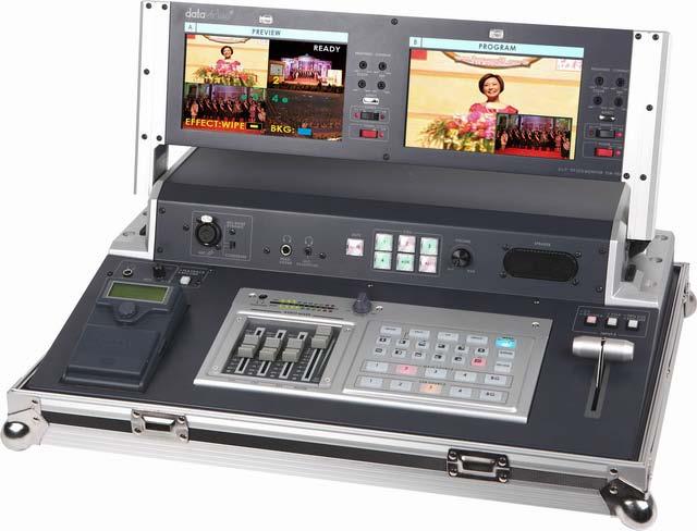
6 Introduction The Datavideo HS-550 is a compact, portable one box solution, built around the Standard Definition SE-500 mixer/switcher. It has been designed with value for money and performance in mind as well as for users where weight and set up time matters. Perfect for applications within education, places of worship, internet streaming, event & live staging, conferences, race meetings, golf tournaments and many more. The HS-550 is supplied complete in a practical and light weight aluminium carrying case, for easy transport and secure storage. There are 4 input video channels which include Composite video for channels 1, 2 and 3. Input channel 4 can be fed from a choice of Composite Video or DVI or VGA sources. The DVI and VGA inputs support a computer graphic card resolution of 1024x768 much like a scan converter. This allows full screen computer PowerPoint presentations to be included in HS-550 productions. The mixed video or program output connections are Composite Video and DV25. These can be taken to a Digital Video CF Card recorder like the DN-60, a Hard Drive recorder like the DN-200, a Tape Deck, a DVD recorder or Web Streaming computer. Features The HS-550 system includes an SE-500 mixer, a TLM-702 Monitor (with 2x7 TFT LCD panels), a DAC-200 analogue to digital Converter (installed inside) and the ITC-50 talkback unit. A DN-60 recorder can also be used with the HS-550 DV output but this recorder is purchased separately. Integrated Solution HS-550 is fully integrated with factory fitted cable loom and separate power supply. Connection to video sources (such as camcorders) is made easy with full access to the rear panel for Composite BNC, DV, DVI, VGA, RCA audio and 5pin XLR talkback connections. Ergonomic Design The aluminium case has been especially designed to make operation extremely comfortable, and set up / break down very quick and efficient. Strong Pivot Points These allow easy adjustment of the viewing angle of the high quality TLM TFT LCD monitors. Aluminium Carry Case The HS-550 is supplied complete in a practical and light weight aluminium carrying case, for easy transport and secure storage. 5
7 Overview HS-550 HS-550 Front Panel A B C D E F Audio faders 2. Headphone Socket 3. Audio meters 4. Headphone Volume Control 5. Video Effect: Quad 6. Video Effect: Split 7. Video Effect: PIP 8. Video Effect: Freeze 9. Background color selection/menu 10. Border On/Off 11. T-Bar 12. Transition Effect preview 13. Main Video Source selectors 14. Sub Video Source selectors 15. Transition mode selectors NOTE : The DN-60 CF Card Recorder shown above is supplied separately A. Headphone Socket (DN-60) B. Volume Control (DN-60) C. Playback/Record selectors (DN-60) D. CV/DVI/VGA source selectors E. VGA/DVI source selectors F. 90%/95% size selectors 6

8 1. Faders: sliders to control audio levels for the Main audio output mix. These Audio Level pots are the first stage in the audio signal path. Analog audio comes in through the 1/4 inch phone jack and RCA connectors on the rear panel see Rear Panel. 2. Headphones jack: accepts a stereo mini jack plug for stereo headphones. The headphone volume is controlled by the Headphone volume control (4.). 3. Audio Meters: LED style meters, which show the signal strength at the Audio Output. The signal measured is determined by the levels set with the Faders (1.). The LEDs turn red at +10 db to indicate clipping distortion. For more information, see Audio Inputs, Levels, and Meters. 4. Headphone volume control: controls Headphone level and signal(s) present at the Headphone jack (2.). Level is controlled by the rotary knob. 5. Quad Video Effect: combines four different input sources into one single output on program monitor. 6. Split Video Effect: split the selected Sub Video Source and the Main Video Source into left and right half size video screen. Use left and right function key to swap sides. For more information, see Using Effects: Split. 7. Picture in Picture: puts the selected Sub Video Source in a window on the Main Video Source, with control over window size and placement. Used in conjunction with the Border keys (10.) For more information, see Using Effects: Picture in Picture 8. Freeze Video Effect: will grab the last field from the Main video output and hold it as a still image. For more information, see Using Effects: Freeze. 9. Menu: Press and hold the button BACKGROUND COLOR for 2 seconds or more, a menu will pop up. You are able to change the camera settings, which include Brightness, Contrast, color, Tint (NTSC only). For more information, see Color Processor. 10. Border: controls the border style and color for the Picture in Picture effect, and the color edge for the Wipe effect. This control is accessible when the Picture in Picture controls and Wipe transitions (15.) are engaged. For more information, see Using Effects: Picture in Picture, and Using Transitions: Wipe. 11. T-Bar: used to manually perform a transition. For more information, see Playing a Transition. 7


 and HS-550 speaker Level is controlled by the rotary knob. C. Playback/Record selectors: Used to select which of the (DN-60) PLAY BACK or RECORD.")
.")
9 12. Preview: preview the selected transition effect, and background color by pressing the Preview button. 13. Main Video Source Selector: Used to select which of the four video input channels or background is sent to the Main video output. For more information, see Video Source. 14. Sub Video Source Selector: Used to select which of the four video input channels or background will be transitioned to or used as a sub source in an effect. 15. Transition selectors: These twelve selection buttons determine the transition type and allow for the selection of certain effects that are performed on the selected Main Video Input channel. A. Headphone Socket: accepts a stereo mini jack plug for stereo headphones. The Headphone volume is controlled by the Headphone volume control (B.). B. Volume Control: controls Headphone level (DN- 60) and HS-550 speaker Level is controlled by the rotary knob. C. Playback/Record selectors: Used to select which of the (DN-60) PLAY BACK or RECORD. # When the switch LED light on are RECORD function enable. D. CV/DVI/VGA source selectors: Used to select which of the CV/DVI/VGA output. # When the switch LED light on are DVI/CV function enable. E. VGA/DVI source selectors: Used to select which of the VGA/DVI output (Please set CV/DVI/VGA mode on DVI or VGA first). # When the switch LED light on are DVI function enable. F. 90%/95 size selectors: Used to select the 90%/95 size, (for Computer display size). # When the switch LED light on are 95%SIZE function enable. 8
10 HS-550 Rear Panel 12 11b 10b 11a 10a DVI / VGA Monitor Output 2. DVI Input (input Ch4) 3. VGA Input (input Ch4) 4. Video inputs, Channels 1, 2, 3, 4. Composite video input (BNC) 5. Microphone input Ch1, 2 (1/4 jack) 6. Audio inputs (Stereo, RCA connector) 7. DV Output 8. DC Power input 12V 10A 9. Power On / Off switch 10. a & b Composite video outputs 11. a & b RCA Audio outputs (L+R) 12. TO BELTPACK (For Intercom) 1. DVI / VGA Monitor Output This connector allows for a single DVI- D or VGA monitor output. 2. DVI Input DVI-D Signal Input (See Item D on Page 7) Supports DVI resolution 1024x VGA Input VGA Signal Input (See Item D on Page 7) Supports VGA resolution 1024x Video In Composite video inputs: takes a BNC connector from the composite output of a VCR, camera, DVD player, etc. 9
11 5. Microphone input MIC CH2:A ¼ jack connector for a high impedance analog audio source, such as a microphone. MIC inputs 1 and 2: accept ¼ Inch mono plugs, carrying high impedance signals from one or two mono microphones. With high impedance MIC, the longer the cable from microphone to the SE- 500, the more noise is introduced into the signal. MIC CH1: When a stereo ¼ jack is connected to CH1 only, the CH1 and CH2 Faders will have equal volume on each channel. When both CH1 and CH2 have a MIC connected, each fader channel will adjust the respective input from the rear panel. 6. Audio Input RCA stereo for a line level auxiliary analog audio source, such as a CD player or tape deck. If you are using more than two sources via an external audio mixer, connect the audio mixer s line level output to this unbalanced Audio input. 7. DV Output 6 Pin DV Out Port. Port for connecting to a PC for video capture or to a DV Monitor (TLM-70D). 8. DC Input DC in socket connect the supplied 12V 10A PSU to this socket. The connection can be secured by screwing the outer fastening ring of the DC In plug to the socket. 9. Power On / Off switch Switches the unit On / Off. 10. Video inputs Composite video input: takes a BNC connector from the composite output of a VCR, camera, DVD player, etc. 11. Audio Output An RCA stereo line level analog audio output, carrying the signal present at the output of the audio mixer section. 12. TO BELTPACK (For Intercom) Each of the 5 channels has an XLR connector that carries bi-directional signals between the ITC- 50 and ITC-100SL. All connections are contained within the one cable. 10
12 Monitors Quad Preview and Program The HS-550 comes with two monitors one for Preview and one for Program. These monitors help you choose your video sources and decide when to cut or transition between video sources. The Left hand Monitor is split into a 4 screen quad labelled PREVIEW and is referred to as a Quad Preview. This Quad Preview shows the video sources connected to the HS-550. To help you match the video shown to a button, or an input, each section of this Quad Preview is labelled; 1 to 4. The labels in this Quad preview are also colour coded. A Red flashing label indicates this is the selected video source that is already being sent to the HS-550 s Program output. A Yellow label indicates that this is the selected Sub source that will be transitioned to if the T- Bar is moved. A Green label indicates a video source that is not currently selected. The colour coding of these labels can be referred to as an on-screen tally system. The Right hand Monitor is labelled PROGRAM and only shows the main mixed output of the HS-550. This monitor output will only be sub divided if the PIP or SPLIT or QUAD effect is active. In the above example input 1 starts as the Main source (Red) and input 4 is the selected Sub source (Yellow). As input 1 is the Main source this should also be seen on the Program monitor too. When the T-Bar is moved the Program Monitor will transition from input 1 to input 4. When the T-Bar has been moved fully the label for input 1 will be Yellow and the label for input 4 will be Red. Another Sub source which is currently labelled Green can then be selected as the Sub source to be transitioned to next. Completing a manual transition The HS-550 two way T-Bar is used for performing manual transitions between video sources; it can be moved either all the way up, moved all the way down, or moved part way in between. The top and bottom positions for the T-Bar are relative, meaning one position is before and one position is after the transition being performed. The HS-550 completes the selected transition between two sources at the same speed as you move the T-Bar. If no transition type is selected, moving the T-Bar performs a default fade or dissolve between the two selected video sources. 11
13 Dissolving or Fading between sources Select the Main Video Source by pressing an appropriate channel button. The button for the channel you have selected should be illuminated Red and you should immediately see that source on the Program monitor. Now select the Sub Source that you want to dissolve to, illuminated Yellow. The default transition is a fade/dissolve (this button will already be lit when you first turn on the switcher). Move the T-Bar to the opposite position and watch the fade happen between the sources on the Program monitor. Cutting between sources The HS-550 can do 3 kinds of transitions: fade (already covered in the previous section), cut and wipes. The cut is a simple switch from one input source to another. Not flashy, nor fancy, but it gets the job done. In fact, if you watch a film or video, paying attention to the transitions, you will see that the cut is the most often used transition. You select a video source by pressing one of the buttons 1, 2, 3, 4 or BG (Background colour). For example, if you press button 4 on the Sub Source row your selection will be confirmed by the same button being illuminated. The chosen Sub Source button is illuminated Yellow. The chosen Main Source button is illuminated Red. When a Main Source button is pressed the main output of the mixer immediately shows or cuts to that video source on the Program monitor. This means that you can perform simple cuts between video sources just by pressing different buttons on the Main Source row. Pressing a Sub Source button may not cause an immediate change to the HS-550 s main output or Program monitor. The selected Sub Source button (illuminated Yellow) only identifies which video input source will be next shown when using the T-Bar. Wiping between sources Select the transition wipe button that you wish to use. There are in total 11 different Wipe styles and the corresponding transition icon will be displayed in the bottom left corner of the Preview monitor when you press it. The last button on the bottom row (see above picture) with a checker board marking is the Dissolve/Fade button. At this point you could also press the Preview button, to see a sample of the selected transition on the Left hand HS-550 Preview monitor. This Preview is for confirmation only and is not sent to the main outputs or the Program monitor. Once this Preview is finished the monitor will return to the Quad view. In a wipe transition, the change from one source to another happens along a predefined edge. It is like one source image is being pulled back or pushed on top of another source image. Depending on the button selected the starting point and direction of the wipe is changed. But a picture is worth a thousand words, so... try this Select a main source and sub source, select a Wipe, or Fade from the buttons above, press the Preview button and see what it would like. Then, perform the actual transition manually by moving the T-bar up and down. See the next page for a list of wipe transitions and variations. 12
14 List of Wipe transitions and parameters (suitable for photocopying) Any Wipe works in conjunction with the Border control. A represents the current source and B represents the sub source that will replace A during the transition. Vertical wipe, from middle out to left and right sides at the same time. Vertical wipe, from left to right side. Horizontal wipe, from top to bottom of screen. Right angle wipe, from upper left corner to lower right corner. Right angle wipe, from upper right corner to lower left corner. Block wipe, from center to full screen. Horizontal wipe, from middle out to top and bottom at the same time. Vertical wipe, from right to left side. Horizontal wipe, from bottom to top of screen. Right angle wipe, from lower left corner to upper right corner. Right angle wipe, from lower right corner to upper left corner. Dissolve or Fade from Main source to Sub source 13
15 Effects There are two places on the HS-550 where you can add effects: in the Transition Effects section (15.) and in the Video Effects section (5-8.). Some of these work on a single source, and some need two or four sources to work. Select a Main Video source and try the following: In the Transition Effects section, select the WIPE effect you wish to use. You could also add a border to the edge by turning on the BORDER effect (10.). In the Video Effects section, try the Quad effect (5.). Press the button to engage the effect; the LED will light. You can see all 4 input sources showing on the program monitor at the same time. No other cuts or transitions can be performed until the Quad effect is toggled off. For Split effect (6.), select a sub source for right hand side window. Then, press the SPLIT button. You will see Main source on left hand side, and Sub source on right hand side. Simple cuts can be performed along the main and sub source rows. Transitions are not possible until the Split effect is toggled off. PIP effect (7.), which stands for Picture in Picture. As you might guess, this effect requires a Main and Sub Video Source. Assuming you have valid inputs on Channel 1 and 2, select Channel 1 as the Main Source and Channel 2 as the Sub Source. When you engage the effect by pressing the PIP button (and verifying that the LED on the button is lit), on the program monitor you will have Channel 1 as the Main Source and Channel 2 as a smaller PIP window inset. There are two choices for window size. Change these by pressing the + and - buttons, see below. You can position this window using the other five different position buttons on (15.), with the button set to Position Control (LED is lit). You could also add a border by turning on the Border control (10.). Next, try the Freeze effect (8.) to grab a still frame of the Main Source video. Move the T-Bar to manually dissolve away to the Sub Video Source. Using Effects The HS-550 is capable of producing a wide variety of digital effects. These fall into 2 categories: single channel and dual channel effects. Single channel effects are produced on the source selected in the Main Video Source bus and need no second video input. Single channel effects include Freeze. For example, select any input channel having a valid signal as the Main Video Input. Press the Freeze button once. You ll see, on the program monitor, that the source video stops instantly. Press the button again, and watch the source video return to full motion. With the Freeze effect, there are no parameters, just a single source stopping and starting. For more information on single channel effects, see the appropriate section (Freeze) below. 14

16 Dual channel effects are produced on the source selected in the Main Video Source bus and require a second source, which is always selected in the Sub Video Source bus. Dual channel effects include Picture in Picture. For example, select Main and Sub Video Sources, and then press the PIP (Picture in Picture) button; immediately, on the program monitor, you will see the Sub Video Source in a small window. For more information on these dual channel effects, see the appropriate sections (Quad, Split, and Picture in Picture) below. Effects: Quad The Quad effect combines 4 input videos into 1 output. When this effect is activated, it shows the 4 video sources on 1 single monitor. Each source takes one quarter of the entire screen like the Quad Preview. Press the button again, and it returns to the previously selected main source in full screen. This is a dual channel effect, and cannot be used with any other transitions or effects. Effects: Split This effect squeezes the Main Source and Sub Source video into one program screen. The Main Source is placed on the left, and the Sub Source on the right. To select different sources for the left window press different channel buttons on the Main Source row. To select different sources for the right window press different channel buttons on the Sub Source row. You could switch from left to right, or right to left by pressing the LEFT or RIGHT button. This is a dual channel effect, and cannot be used with any transitions. Only simple cuts can be used. Effects: Picture in Picture The Picture in Picture or PIP effect puts the selected Sub Source video in a smaller window on top of the Main Video Source. Variables for this effect include changing window size and position. Window size (2 sizes are available); change the window size by pressing the + and - buttons on the left of the Wipe transitions. (+ is larger, - is smaller). There are 9 different positions that are located on the right of the Wipe transition effects. Select from one of the preset locations by using the buttons. On each corner, use Right and Left to move the window closer to the edge or to the center. This effect may also be used in conjunction with the Border effect (see next page). This is a dual channel effect, and cannot be used with any transitions. 15

17 Effects: Freeze This effect freezes the incoming video, as selected on the Main Source row. There are no parameters, no variations. Press the button once and the video freezes, press it again, and it returns to the selected source in full motion. The Freeze effect is single channel, and works in conjunction with any transition. Border This can be used in conjunction with the Picture in Picture Effect and Wipe transitions only, and should be activated before the Picture in Picture or Wipe is active. In PIP mode the border colour can only be white. Wipes have 8 Border colors are available: black, blue, magenta, red, green, cyan, yellow and white. Background While not strictly an effect, this control is related. This control selects what solid colour the background will be when selected on either the Main or Sub Video row. There are eight possible background colours; black, blue, magenta, red, green, cyan, yellow, and white. The button LED lights up in the selected colour with repeated presses of the button (except for black where the LED goes off), and this is also indicated on the quad preview monitor output too. Connecting a computer to the HS-550 Rear input options Channel DVI Input connector (Accepted resolution 1024x768) 2. VGA Input connector (Accepted resolution 1024x768) 3. Composite video The HS-550 has the option to accept Composite, or VGA, or DVI input sources for mixing on channel input 4. This allows the HS-550 to include presentations or graphics from a computer or laptop using the VGA or DVI options of channel 4. As well as connecting the VGA or DVI cabling from the computer to the rear of the HS-550 (see 1 or 2 above) you will also need to select the input type using the configuration buttons above the T-Bar of the mixer (see picture below). 16
 90% size (ON) 95% size Computer Display Set Up For best results preparation is the key, so ensure the following steps are completed BEFORE your event or recording starts.")
18 HS-550 Channel 4 configuration buttons A B C A. Toggle between (OFF) Composite (ON) VGA / DVI input B. Toggle between (OFF) VGA (ON) DVI input C. Toggle Image (OFF) 90% size (ON) 95% size Computer Display Set Up For best results preparation is the key, so ensure the following steps are completed BEFORE your event or recording starts. In order for the HS-550 to see the computer output you may need to extend the computer or laptop desktop to a second monitor using Control Panel as below. When using a laptop you may need to use a function key combination to allow use of the VGA port, much in the same way as using a laptop with a projector. The PC graphics card will need 2 connections 1 for the PC monitor and a spare DVI-D connection to go to input 4 on the HS-550. The PC will need to have Microsoft Office installed in order for PowerPoint to be used. If all the settings are correct on the mixer and the PC then we can attempt to use this DVI-D PC display output as part of our HS-550 mix. 1. Connect a DVI-D cable between the HS-550 and the spare DVI-D port on the PC s graphics card. 2. Turn on the HS-550 and then the PC. 3. Create a PowerPoint presentation with Black text on a white background. You may want to create your own Slide Master within PowerPoint. Use the PowerPoint Help function for advice on how to do this. 4. Select channel 4 on the Main source rail of the HS-550 so it is shown in the PROGRAM window. If you cannot see the computer output extend the PC s desktop within Windows to monitor 2 as below. 5. PC screen size for monitor 2 should match the 1024x768 resolution. 6. If the DVI input or program monitor is just a blue screen (blue desktop background only), then try using the PC mouse pointer to drag a window or a desktop icon across and onto the HS-550 DVI PROGRAM window. 7. OK, so you should now have the Monitor 2 PC display running into input 4 on the HS
. 9.")


19 8. Open up Powerpoint on the PC and use Set Up Show so that the presentations play back on Monitor 2 (the HS-550) and the presentator s output is sent to Monitor 1 (the PC s own monitor). 9. Run the Powerpoint presentation and you should see it playing back on the HS-550 PROGRAM window. 10. Now you can attempt to work the presentation or graphics into your mix, either on its own or with the speaker in a smaller PIP window. 11. Note if you plan to use the PIP window effect then select the speaker as the sub source input before pressing the PIP button. The presentation layout also needs to be adjusted to leave space for the PIP window. Recording from the HS-550 with an optional DN-60 A A. Toggle between (OFF) allow DN-60 Playback to HS-550 (ON) allow DN-60 to Record 18
 in the above picture needs to illuminated Red.")
20 HS-550 DV port Set Up The HS-550 has 2x DV / IEEE-1394 ports, one on the rear plate for connection to a DV deck, Camera or Computer and one dedicated for seating a Datavideo DN-60 recorder to the left of the HS-550 mixer area. In order to record from the HS-550 using these DV / IEEE-1394 ports the Button (labelled A) in the above picture needs to illuminated Red. Once active these ports will send DV25 signals to the connected equipment. If the button is off (not illuminated) then the DN-60 port will accept playback of recorded clips from the connected DN-60. These clips can be viewed by switching the Program Monitor on the HS-550 to the V2 position. Remember to return the HS-550 monitor and DV port button back to their original settings before attempting to mix/record again. It is not possible to play 2 DV devices into the HS-550 at the same time this will only cause the external devices to become un-responsive as they are both trying to access the same channel. DN-60 - A brief Set Up guide The DN-60 is not supplied with the HS-550. What follows is a brief outline of how to use the DN-60 to record from the HS-550. A full PDF version of the DN-60 manual can be obtained from your dealer or local Datavideo office. The DN-60 records the mixed Program output, video and audio, from the HS-550 via the DV / IEEE-1394 port on the HS-550 top panel. This port needs to be seated correctly with the DN-60 in order for the signals to be received properly. When seated, the HS-550 does not supply power to the DN-60. Instead the DN-60 still needs to be powered from internal batteries or its own power adaptor. The DN-60 should be switched on after being attached to the HS-550. DN-60 Connections & Controls Front Panel 1. LCD Panel Shows the status and menu options of the DN Menu Navigation Button Rotate to change options and press in to select 3. DC Power input Connect the DN-60 power adaptor here 4. Status LED 5. Power On / Auto / Off switch 6. CF Card Protection Cover Slide down then lift up carefully to gain access 19

, this button is normally in the depressed position.")
21 Rear Panel CF Card Slot 1. Battery Compartment Cover Press in gently and slide up to access 2. Camera Mount screw thread Attach DN-60 camera mount here 3. DV/DVC Pro/HDV i/o Port Attach 6pin IEEE-1394 cable connector here 4. RS-232 Port Connect 3.5mm Jack for RS-422 control by computer 1. CF Card Protection Cover Slide down then lift up carefully to open this cover and get access to the CF card slot and the card eject button. 2. CF Card Eject Button Press in to eject the fitted CF card. When the slot is empty (no CF card inserted), this button is normally in the depressed position. Upon inserting a CF card, the button moves out again. NOTE: CF cards need to be inserted carefully the correct way up so that the pins inside the unit marry correctly with the card holes otherwise damage to the pins may happen. Do not force a card into the slot or force the card protection cover. 20
 0.")
22 DN-60 Powering On Connect the DN-60 s own power adaptor to the right hand side DC In socket. Ensure the power adaptor unit is connected to a suitable mains socket. Switch the power ON/OFF switch on the Left hand side of the unit to one of 3 positions. 1. Manual power ON position A. Auto power ON/OFF position (DV port button is switched on/off) 0. Manual power OFF position DN-60 Status LED and Error Messages The LCD display panel will show Datavideo DN-60 Loading after a few seconds the Home Display will be shown. The DN-60 is now ready for set up or use as a recorder or playback device. The DN-60 has a red status LED just below the Menu Navigation Button. This can be used as a quick way of confirming that the unit is working correctly or is requiring user attention. LED constantly ON Indicates the DN-60 unit is recording a camera/source input. LED constantly OFF DN-60 is idle or the unit is waiting to be powered on. LED Slowly Dimmed OFF and ON Indicates record pause, formatting card, or making media file. LED Flashing ON and OFF The LCD panel will also indicate that there is: No Media - CF card is not detected by DN-60. Check CF card. No Input - Video signal is lost from DN-60. Check cabling and source equipment. Bad Input - Video signal received does not match the DN-60 settings. Unsafe Battery level - usually indicates low battery level. Change batteries or power source. Wrong Format Media!! - CF card does not match the format settings of the DN-60. User can choose "RESTORE SETTING": Reset DN-60 configuration to accept the CF card inserted. Or "FORMAT MEDIA": Format the CF card according to current DN-60 configuration. Caution: All content on the CF card will be erased by selecting "FORMAT MEDIA" DN-60 Menu Navigation Pressing the Navigation Button in will select the menu option or confirm a value. Rotating the Navigation Button in either direction will change the menu option or set a value. If all options have been displayed then the menu display will only scroll options in one direction. Choose EXIT to return to a previous menu level or to return to the initial Home screen (shown below). The DN-60 is a menu driven unit; there are several menus which are used to set up the unit. The menu settings are non-volatile (settings are stored even when the unit is switched off). So general settings, such as Signal and File types, will only need to be set once. A brief overview of the DN-60 menu options follows. A full PDF version of the DN-60 manual can be obtained from your dealer or local Datavideo office. 21

23 When using the DN-60 with the HS-550 ensure the unit is setup using the following steps. CF Card Ensure your chosen Compact Flash (CF) card is qualified for use with the DN-60. If you are not sure check with your local dealer or Datavideo office. Back up any data to computer that is already on the CF card before inserting the card into the DN-60. Set the Signal Type Use the menu path Setup, System Set Up, Set Signal Type to configure the DN-60 unit for a Signal Type of DV+DVC 50Hz (PAL area) or DV+DVC 60Hz (NTSC area). Set the File Type Use the menu path Setup, Record Setup Options, Set File Type to configure the DN-60 unit to create the file type that is required by your computer edit software. Available choices are Microsoft AVI, Canopus AVI, QuickTime MOV or Avid MXF (OP1A). Set the File System as FAT32 or NTFS Set up the file system type seen on the CF card by the computer when transferring files. The FAT32 file system is compatible with both Macs and PCs. However, this format limits the size of a file to 2GB, in DV25 that translates to approximately 9 minutes of video. A clip or recording that lasts longer than 9min is spread across multiple files, each 2GB long, with the last file in the sequence making up any remainder time. If this sequence of 2GB files are placed in the correct order and end to end on an editing time line the recording will play through as one whole recording again. The NTFS format is fully compatible with PCs and is read compatible with Macs. Its main advantage is that it does not impose a file size limitation to the DN-60 files resulting in one file per recording. Note: When using 64GB cards, if you plan on shooting one continuous take greater then 3 hrs (using NTFS setup) please note that some Non-Linear Editing Software cannot accept file sizes greater than 40GB, please make sure your NLE is not one of them before you plan to shoot. Set the Record Date (optional) Use the menu path Setup, Record Setup Options, Set Record Date to enter today as the date for the files being recorded. Starting the Recording Once you are ready to start the recording with the DN-60 navigate to the Record Mode menu option and then press in the navigation button. Select an empty Bin Video clips are recorded into Bins on the DN-60. Bins are numbered from 0 to 99. Use the Bin/folder option to select an empty bin. An empty Bin will display as 00:00:00;00 on the DN-60 LCD panel. Recording Once an empty bin has been chosen rotate the menu navigation button until the record circle icon is shown then press in the navigation button to start the record process. You should see the Timecode counter value increasing. End recording To stop the record process rotate the menu navigation button until the square stop icon is shown then press in the navigation button to end the recording. You should see the Timecode counter value remain on the same value which also equals the full length of the recording in hours, minutes, seconds and frames. So 00:23:15;06 would equal a total record time of zero hours, 23 minutes, 15 seconds and 6 frames. Prepare the files for editing Before removing the CF card from the DN-60 and before using the DN-60 CF card with a computer and seeing your video as files instead of clips the MAKE MEDIA FILES menu process under TOOLS mode must be undertaken otherwise the computer may see a blank card. This menu operation prepares the recorded video content on the CF card to be seen by a computer by building pre-selected file wrappers around the recorded content and emulating the chosen computer file system. It takes roughly 1 minute to prepare 1 hours worth of video. 22
; to monitor through an amplifier and speakers, push the MASTER fader to -12 in the Audio Faders (1.) section.")
24 HS-550 Audio Inputs, Levels, and Meters Audio Monitoring For output audio monitoring with headphones, set the rotary headphone volume control knob to the center. (4.); to monitor through an amplifier and speakers, push the MASTER fader to -12 in the Audio Faders (1.) section. Audio Input Level Calibration Procedure The first step in setting up the audio for a session with your SE-500 consists of adjusting the levels on which channel you will be using. Slide the Master fader to Max, and set the other faders to 0. Then, listening to the audio and watching the Audio Level Meters (see below), set the level with the fader so that the sound is consistently at between +0 db (green LED) and +8 db (yellow LED) and just barely peaks occasionally to +10 db (red LED). The idea is to avoid any audible distortion (clipping), caused by making the signal level too high at this stage. Three faders on the left represent the input volumes (CH-1, CH-2, AUX), which determine what signals are present at the Main Output. If any of the faders are all the way down, there will be no audio from that input channel heard at the output. These faders correspond with each input and control the relative volume of each input in the master output as well as the master output level. When the faders are set to 0, they pass the audio signal through at the same level it was at when it entered this bus. You can increase or decrease the volume of each channel by moving the fader up or down. These meters show the audio signal level at the Main output. The strength of any audio signal that is routed to the output will be displayed here. As mentioned above, these meters play a vital part in correctly setting the audio levels to avoid clipping or other distortion. You ll notice that the LEDs are green up through the +0 db level, turn yellow at +4 db, and turn red at +10 db. As you set the audio level for each input, make sure that the signal peaks to +8 db or very occasionally to +10 db. Every time the signal goes to +12 db, it will be distorted. Use the Headphone section to accurately monitor with the Master volume output. In many cases, headphones may be a more useful and accurate choice than speakers for audio monitoring. For example, in a noisy club or at a concert, you won t be able to hear any additional sound coming through speakers. Headphones will also more accurately reproduce the sound you wish to monitor at a lower cost than speakers. 23
 controls on a Time Base Corrector.")
25 Menu - Color Processor The Color Processor controls work when you press and hold the Background (9.) button for 2 seconds or more, which is temporarily displayed at the Preview Output. The controls shown are like picture controls on a video monitor or the proc amp (processing amplifier) controls on a Time Base Corrector. In fact, they are the proc amp controls of one of the SE-500 s 4 internal TBCs. At the top of screen you will see 4 different channel numbers, each represent an input from the SE-500 rear panel. On the left side of this table are the 4 controls (Brightness, Contrast, Color, and Tint (NTSC only)). Value 0 stands for Unity, or Unchanged. In either case, it shows that the signal passing through that particular control is neither boosted nor reduced. To move to another control, press the up or down arrow button. To move to another channel, press the left or right arrow button. To change the setting, press the + or - buttons Brightness ±0 ±0 ±0 ±0 Contrast ±0 ±0 ±0 ±0 Color ±0 ±0 ±0 ±0 Tint* ±0 ±0 ±0 ±0 You can see the extent of color processing available in this section by experimenting with the controls. Brightness adjusts how light or dark the colors in the image will appear at the Video Output. The Contrast controls affect the range between the lightest and the darkest parts of the image, including how much shadow and highlight detail can be seen. Color controls the saturation or intensity of the color image, from fully saturated or extremely intense at the top of the scale to de-saturated or monochrome (black and white) at the bottom. The Tint value controls the actual hue or specific colours in the image (NTSC only), in effect rotating all the colours equally around an imaginary colour wheel. Reset Works on the selected input source, and when pressed and held for 2 seconds, resets the Color Processor controls for just that input to 0 or unity. (Press and hold the Reset button until you see the image shake a bit and return to the unprocessed state.) So how do you know for certain how effective any of these adjustments are? You can see the changes by looking at the Main Output on a video monitor, but how do you know if that reference is accurate? The answer is: by having a calibrated monitor that shows exactly, with reference to a standard, what the video looks like. That standard has been described and agreed to by the Society of Motion Picture and Television Engineers (SMPTE) and the European Broadcasters Union (EBU), and is most commonly shown as color bars. Color bars are an image consisting of columns and blocks of specific colors and gray tones. Because of differences in television standards, SMPTE bars and EBU bars do not look the same. They are used in much the same ways: when these are displayed on a monitor, the monitor can then be adjusted to meet the standard. 24
26 SE-500 Specifications Video Formats Analog Y/C, Composite CCIR601 NTSC and PAL (PAL and NTSC units are separate models) Video Inputs 4 Composite Video Output 1 Quad Video source monitoring (Composite) 2 Composite Audio Inputs 1 Stereo input (RCA connector) 2 Mono Microphone (1/4 phono jack) Audio Output 1 Stereo main outputs (RCA connector) 1 Stereo headphone (Mini jack with volume control) 0.3Wrms 8 ohm Quad Channel Time Base Correction Full Frame Synchronization, 4:2:2, 13.5MHz Digital Effects including A/B dissolves, PIP, border lines, and over 12 Wipes with various manually transition speeds Color Processing Brightness +/-10% Y-gain (Contrast) +/- 3dB Color +3/-10dB Tint +/- 10 degrees (NTSC only) Video Bandwidth Component 5.2 MHz S (Y/C) 5.0 MHz Composite5.0 MHz DG, DP +/- 3%, 3 degrees Signal/Noise Ratio: Video > 50 db Audio > 65 db Audio 20 to 20KHz +/-1dB Audio THD <0.1% Power Input: DC 12V, 1.5A 25
 Jack Microphone Input for either a Condenser or Dynamic Gooseneck Microphone. XLR supports Condenser Microphones ¼ (6.")
27 ITC-50 Intercom Controls XLR Microphone Socket 2. Headphone Socket 3. Microphone / Headset Socket 4. MUTE Button 5. 1~5 & ALL Channel Buttons 6. Volume Control 7. Built-In Speaker XLR Microphone Socket Combined XLR / ¼ (6.3mm) Jack Microphone Input for either a Condenser or Dynamic Gooseneck Microphone. XLR supports Condenser Microphones ¼ (6.3mm) Jack supports Dynamic. Headphone Socket ¼ / 6.3mm Stereo Headphone Socket for conventional headphones. Plugging in headphones will disable the built-in speaker Microphone / Headset Socket 3.5mm Stereo Socket for combined Microphone Headset. Plugging in a Microphone / Headset will disable the built-in speaker and the XLR Microphone Input. MUTE Button Mutes all communication from the base station or any channel. N.B. If any channel uses the CALL button the paging tone will still sound even when the MUTE button is active. Channel Buttons Opens communication with individual channels. More than 1 channel can be active at any given time, active channels are illuminated red. All active channels will hear any communication from the operator or from any other active channel. The buttons will also indicate if any channel is paging, the paging channel will flash in orange until the page is answered. Opens communication with all channels. All channels will hear communication from the operator, or from any other channel using the TALK button. Volume Control Controls the Volume of the built-in speaker or outputs to the headphones or mic/headset according to what is connected Built-In Speaker Sounds audible alert when a channel is paging and provides audio during talkback conversations. Speaker is mute when headphones or mic / headset are connected to the ITC-50 26

28 ITC-100SL Slave Unit XLR Connection Connects the ITC-100SL to the ITC-100 Base Station. Power, tally and bi-directional audio are all carried through the same CB-3 cable. Call Button Sends a paging message to the ITC-100 Base Station. The channel button will flash orange and there will be an audible tone, each time the button is pressed. Bi-Color Tally LED Will illuminate RED when the channel is LIVE and AMBER when the channel is CUED Talk Button Opens up talk back communication with the ITC-100 base station, and any other active channels. Volume Control Adjusts the volume of the headphones. Mic / Headphone Socket The ITC-100SL has both a 3.5mm and 2.5mm Mic / Headset socket. A standard 3.5mm Mic / Headset can be used, or a Motorola type 2.5mm Mic / headset could be used if preferred. External Tally LED Socket An external tally display (TD-1) can be connected to the ITC-100SL. This enables the tally light to be positioned in a more convenient place, such as on top of the camera. When the channel is LIVE the LED will be RED, and when the channel is CUED the LED will be AMBER. N.B. The Tally LED on the ITC-100SL will continue to operate as normal when a TD-1 has been added. Power LED The Power LED indicates when the channel is active. If the operator has opened the channel by pressing the channel button 1 ~ 8, or by pressing ALL then the LED will light up. N.B. The tally indicator lights will continue to work even when the Power LED is not on, and the channel is not active. 27
29 Cable Assignments Headset, Jack plug and 5pin XLR Please Note: If you only want to extend the reach of the ITC-100SL Belt Pack cabling then Datavideo already sell pre-manufactured XLR cabling for doing this in 20m (CB-3) and 50m (CB-4) lengths. Please ask your local dealer for price and availability of additional CB-3 and CB-4 cables. ITC-100 XLR cable / 5pin XLR Connector on ITC-100SL Pin Cable Assignment 1 Red Tally Red 2 Black Tip (Talk & Call) 3 Shield Common with Ground of XLR 4 Green +12v DC power to ITC100SL 5 White Tally Yellow 5pin XLR Cable is a straight through cable pin 1 to pin 1, pin 2 to pin 2 etc ITC-100SL Belt pack 3.5mm Jack socket Headset connector Please Note: For connecting a professional headset Datavideo can supply a mini jack to XLR adaptor cable which would support headsets with a Dynamic microphone. Please contact your dealer or local Datavideo office for more information on this XLR to Jack plug adaptor cable. In the case of a professional headset with an Electret microphone a small SDM of 1yf/1uf (for decoupling ac) will be required on the Jack Tip/XLR pin 2 cabling. Jack Headset XLR Assignment Tip Pin 2 Microphone (can be Dynamic or Electret) Ring Pin 4 Earphone (Impedance range 8-100Ω) (ideally 30-40Ω) Ground/Sleeve Pins 1 & 3 Common Ground 28

.")


30 TLM-702 Functions - Front Panel 1. Each monitor has a two color tally light indicator which can be connected to the Datavideo RMC 140, SE500 or similar products. AMBER indicates Cued and RED indicates Live. 2. Each Monitor has individual adjustments for Brightness, Contrast, Color and Tint (Tint is for NTSC only). These four adjustments can be adjusted with a X headed screwdriver. It is recommended that you use a Test Pattern to adjust the monitors. 3. The ASPECT button switches the aspect ratio from 16:9 and 4:3. 4. Source select switches between video input 1 and video input 2. A PREVIEW: V1 Preview, V2 Not in use. B PROGRAM: V1 Program, V2 DN-60 Play back. 5. Power On / Off switches the monitor On or Off On either side of the TLM-702 are small Allen Key screw tension adjustments. These alter the tension on the pivoting mechanism. If you want to change the angle of the monitors, i.e. aim them up or down, you can loosen these screws and adjust the TLM-702. Once you have set the correct angle tighten the screws back up. 29


31 Functions - Rear Panel The earth terminal can be used with other equipment that has the same feature. Connect all items together to ensure that they are grounded. Connect the supplied switch mode power supply to this socket. The locking collar screws into place once the plug has been inserted. It is also possible to power the TLM-702 from other regulated 12V supplies (min 1.5A). 3.5mm Jack Socket for tally light connection. You can connect the tally feed from the Datavideo SE 500, RMC-140, RMC90 or other similar equipment. Each monitor has two composite video inputs, each with a loop-through output. The video input can be PAL or NTSC, the TLM-702 will automatically detect the video standard. TLM-702 Specifications LCD Display 7" x 2 TFT LCD active matrix, resolution 1440 x 234 dots Aspect Ratio 4:3 and 16:9 selectable Brightness (Luminance) 500 cd/m² Contrast Ratio 300 View Angle Top: 40 deg Bottom: 60 deg Left: 60 deg Right: 60 deg Video Input CV input 1.0Vp-p, with self Loop-Through output (75 Ohm-terminated) Video System NTSC/PAL auto recognition Color Adjustment Brightness, Contrast, Color, Tint (Tint is NTSC only) Tally Indication Two Color Tally LED indicators Operation condition Operation temperature from 0 to 50, RH less than 90% Power Consumption DC12Volt, 2.0Amp Dimension of LCD Panel 484mm x 133mm x 50mm (W x H x D) 30
Table of Contents FCC COMPLIANCE STATEMENT... 4 WARNINGS AND PRECAUTIONS... 4 WARRANTY... 5 STANDARD WARRANTY... 5 TWO YEAR WARRANTY... 5 DISPOSAL...
 1 Table of Contents FCC COMPLIANCE STATEMENT... 4 WARNINGS AND PRECAUTIONS... 4 WARRANTY... 5 STANDARD WARRANTY... 5 TWO YEAR WARRANTY... 5 DISPOSAL... 6 1. INTRODUCTION... 7 FEATURES... 7 2. CONNECTIONS
Contents. Disclaimer of Product and Services Warnings and Precautions Standard Warranty Two Year Warranty Introduction...
 Contents Disclaimer of Product and Services... 3 Warnings and Precautions... 5 -Standard Warranty... 5 -Two Year Warranty... 5 Introduction... 6 Features... 6 Setup Diagram... 7 Connections & Control...
.Power Distribution Center. PD-1. Instruction Manual
 .Power Distribution Center. PD-1 Instruction Manual www.datavideo-tek.com 1 Contents Warnings and Precautions... 3 Warranty... 4 Standard Warranty... 4 Two Year Warranty... 4 Disposal... 4 Packing List...
ITC-200B Quick Start Guide
 INTERCOM BASE UNIT ITC-200B Quick Start Guide http:// www.datavideo-tek.com Warnings and Precautions 1. Read all of these warnings and save them for later reference. 2. Follow all warnings and instructions
2 x 7" TFT LCD MONITOR TLM-702HD
 2 x 7" TFT LCD MONITOR TLM-702HD Instruction Manual Rev 150310 www.datavideo-tek.com Table of Contents Warnings and Precautions... 3 Warranty... 4 Standard Warranty... 4 Two Year Warranty... 4 Disposal...
TBC & Matrix Switcher TBC-5000 Instruction Manual
 TBC & Matrix Switcher TBC-5000 Instruction Manual www.datavideo-tek.com Rev 150509 1 Contents Warnings and Precautions... 3 Warranty... 4 Disposal... 4 Packing List... 4 TBC-5000 Features... 4 Product
4 CHANNEL MIXER / SWITCHER SE-500. Instruction Manual.
 4 CHANNEL MIXER / SWITCHER SE-500 Instruction Manual www.datavideo-tek.com Table of Contents Warnings and Precautions... 3 Warranty... 4 Standard Warranty... 4 Two Year Warranty... 4 Disposal... 4 Radio
Contents. Disclaimer of Product and Services
 Instruction Manual Contents FCC COMPLIANCE STATEMENT... 3 WARNINGS AND PRECAUTIONS... 3 WARRANTY... 4 STANDARD WARRANTY... 4 THREE YEAR WARRANTY... 4 DISPOSAL... 4 INTRODUCTION... 5 FEATURES... 5 GO KMU-100
Repeater & Power Adaptor VP-633 HD/SD SDI Repeater VP-634 Quick Start Guide
 Repeater & Power Adaptor VP-633 HD/SD SDI Repeater VP-634 Quick Start Guide www.datavideo.com Warnings and Precautions 1. Read all of these warnings and save them for later reference. 2. Follow all warnings
RACK MOUNT KIT RMK-2 Quick Start Guide
 RACK MOUNT KIT RMK-2 Quick Start Guide www.datavideo-tek.com Apr-22.2013 P/N: G082060691B1 Warnings and Precautions 1. Read all of these warnings and save them for later reference. 2. Follow all warnings
Welcome to the ITC-100 Instruction Manual
 INTERCOM TLK BCK SYSTEM Welcome to the ITC-100 Instruction Manual Thank you for choosing a Datavideo product, please visit the support pages on our website for the latest version of the instruction manual.
TLM 170 / D / M / MD 17 Widescreen LCD TFT Monitor
 TLM 170 / D / M / MD 17 Widescreen LCD TFT Monitor Instruction Manual Rev 060509 www.datavideo-tek.com Table of contents Warnings and Precautions ------------------------------------------------------------------------------------
WARNINGS AND PRECAUTIONS... 3 WARRANTY...
 Table of Contents WARNINGS AND PRECAUTIONS... 3 WARRANTY... 4 STANDARD WARRANTY... 4 TWO YEAR WARRANTY... 4 DISPOSAL... 4 RADIO AND TELEVISION INTERFERENCE... 5 1. INTRODUCTION... 6 1.1 PRODUCT OVERVIEW...
STC-100 Standards Converter
 STC-100 Standards Converter User s Guide http:// www.datavideo-tek.com Rev: 240106 Warnings and Precautions 1. Read all of these warnings and save them for later reference. 2. Follow all warnings and instructions
HD/SD-SDI TO VGA CONVERTER. DAC-60 Quick Start Guide.
 HD/SD-SDI TO VGA CONVERTER DAC-60 Quick Start Guide www.datavideo.com Warranty Standard Warranty Datavideo equipment is guaranteed against any manufacturing defects for one year from the date of purchase.
HD/SD-SDI TO VGA CONVERTER. DAC-60 Quick Start Guide.
 HD/SD-SDI TO VGA CONVERTER DAC-60 Quick Start Guide www.datavideo.com Warranty Standard Warranty Datavideo equipment is guaranteed against any manufacturing defects for one year from the date of purchase.
HD/SD- SDI to VGA Converter DAC-60 Quick Start Guide
 HD/SD- SDI to VGA Converter DAC-60 Quick Start Guide www.datavideo-tek.com Table of Contents Warnings and Precautions... 2 What s in the box?... 4 Introduction... 4 Features... 4 Functions... 5 Front Panel...
DIGITAL VIDEO SWITCHER SD 4-CHANNEL DIGITAL VIDEO SWITCHER SE-500. Instruction Manual
 SE-500 DIGITAL VIDEO SWITCHER SD 4-CHANNEL DIGITAL VIDEO SWITCHER SE-500 Instruction Manual Table of Contents FCC COMPLIANCE STATEMENT... 3 WARNINGS AND PRECAUTIONS... 3 WARRANTY... 4 STANDARD WARRANTY...
POWER INPUT F1 F2 EXIT MENU POWER INPUT F1 F2 EXIT MENU TLM-102 DUAL 10 MONITOR. Instruction Manual.
 POWER INPUT F1 F2 EXIT MENU POWER INPUT F1 F2 EXIT MENU TLM-102 DUAL 10 MONITOR DUAL 10 MONITOR TLM-102 Instruction Manual www.datavideo.com Table of Contents FCC COMPLIANCE STATEMENT... 3 WARNINGS AND
Disclaimer of Product & Services The information offered in this instruction manual is intended as a guide only. At all times, Datavideo Technologies
 TC-100 Table of Contents FCC COMPLIANCE STATEMENT... III WARNINGS AND PRECAUTIONS... III WARRANTY... V STANDARD WARRANTY... V THREE YEAR WARRANTY... V DISPOSAL... VI INTRODUCTION... 1 FEATURES... 1 HOW
FCC COMPLIANCE STATEMENT... 3 WARNINGS AND PRECAUTIONS... 3 WARRANTY...
 Table of Contents FCC COMPLIANCE STATEMENT... 3 WARNINGS AND PRECAUTIONS... 3 WARRANTY... 4 STANDARD WARRANTY... 4 TWO YEAR WARRANTY... 4 DISPOSAL... 4 1. INTRODUCTION... 5 FEATURES... 5 TLM-170L MODEL
Warnings and Precautions
 Warnings and Precautions 1. Read all of these warnings and save them for later reference. 2. Follow all warnings and instructions marked on this unit. 3. Unplug this unit from the wall outlet before cleaning.
HD/SD-SDI to HDMI Converter DAC-8P Quick Start Guide
 HD/SD-SDI to HDMI Converter DAC-8P Quick Start Guide www.datavideo-tek.com Table of Contents Warnings and Precautions... 2 What s in the box?... 5 Introduction... 5 Features... 6 Functions... 7 Front Panel...
Keyer Control Key Source Fill Source Still Load Still Save Still Freeze User Load Memory...
 1 Table of Contents Warnings and Precautions... 4 Warranty... 4 Standard Warranty... 4 Two Year Warranty... 5 Disposal... 5 Packing List... 5 Introduction... 6 Features... 6 System Diagram... 7 Rear Panel...
Network Video Decoder NVD-20. Contents
 Contents Warnings and Precautions... 4 Warranty... 5 Standard Warranty... 5 Two Year Warranty... 5 Disclaimer of Product & Services... 6 Disposal... 6 Packing List... 6 Product Overview... 7 Features...
Table of Contents FCC COMPLIANCE STATEMENT... 3 WARNINGS AND PRECAUTIONS... 3 WARRANTY... 4 STANDARD WARRANTY... 4 THREE YEAR WARRANTY...
 7 4K LCD Monitor Table of Contents FCC COMPLIANCE STATEMENT... 3 WARNINGS AND PRECAUTIONS... 3 WARRANTY... 4 STANDARD WARRANTY... 4 THREE YEAR WARRANTY... 5 DISPOSAL... 6 1. INTRODUCTION... 7 TLM-700K
Contents. Warnings and Precautions...5 Warranty...6 Disposal...6 Packing List...6. Product Overview...7 Features...7
 Contents Warnings and Precautions...5 Warranty...6 Disposal...6 Packing List...6 Product Overview...7 Features...7 Connections & Controls...8 Keyboard Overview...8 Rear Panel...8 Rear Panel Connections...9
Datavideo TLM x 2 TFT LCD Monitors
 Datavideo TLM-702 7 x 2 TFT LCD Monitors Instruction Manual http://www.datavideo-tek.com Rev: 131205 Table of contents Warnings and Precautions -----------------------------------------------------------------------------------2
Teleprompter Remote Controls TP-WRC TP-BTWC. Instruction Manual. Rev Date: P/N: TP Controllers
 Teleprompter Remote Controls TP-WRC TP-BTWC Instruction Manual Rev Date: 03-06-2013 P/N: TP Controllers WWW.DATAVIDEO.COM Contents Warnings and Precautions... 3 Warranty... 4 Disposal... 4 Free App download
Keyer Control Key Source Fill Source Still Load Still Save Still Freeze User Load Memory...
 Table of Contents Warnings and Precautions... 4 Warranty... 4 Standard Warranty... 4 Two Year Warranty... 5 Disposal... 5 Packing List... 5 Introduction... 6 Features... 6 System Diagram... 7 Rear Panel...
Disclaimer of Product and Services - 1 -
 Table of Contents Warnings and Precautions... - 2 - Warranty... - 2 - Standard Warranty... - 2 - Two Year Warranty... - 3 - Disposal... - 3-1. Product Overview... - 4-1.1 Features... - 4-2. Example CCU-100
Contents. Warranty...4. Standard Warranty...4. Two Year Warranty...4. Disposal...4. TLM-170H Model Types...5. Packing List...5. Product Overview...
 Contents Warranty...4 Standard Warranty...4 Two Year Warranty...4 Disposal...4 TLM-170H Model Types...5 Packing List...5 Product Overview...6 Features...6 Supported Formats...7 From a Video Source...8
SE GPI 27 SE-2200
 Contents Warranty... 3 Disposal... 3 Packing List... 4 Connection of SE-2200... 4 Main Unit Front Panel... 5 Main Unit - Rear Panel... 5 Rear Panel Connections... 6 Control Panel... 8 Keyboard Controls...
SD 8-CHANNEL PORTABLE VIDEO STUDIO HS-600 Instruction manual
 SD 8-CHANNEL PORTABLE VIDEO STUDIO HS-600 Instruction manual Table of Contents WARNINGS AND PRECAUTIONS... 5 WARRANTY... 6 STANDARD WARRANTY... 6 THREE YEAR WARRANTY... 6 DISPOSAL... 7 PRODUCT OVERVIEW...
Winmate Communication INC.
 20.1 Military Grade Display Model: R20L100-RKA2ML User s Manual Winmate Communication INC. May, 2011 1 IMPORTANT SAFETY INSTRUCTIONS Please read these instructions carefully before using the product and
17 19 PROFESSIONAL LCD COLOUR MONITOR ART
 17 19 PROFESSIONAL LCD COLOUR MONITOR ART. 41657-41659 Via Don Arrigoni, 5 24020 Rovetta S. Lorenzo (Bergamo) http://www.comelit.eu e-mail:export.department@comelit.it WARNING: TO REDUCE THE RISK OF FIRE
.Prompter Kit for Apple ipad. TP-200
 .Prompter Kit for Apple ipad. TP-200 Instruction Manual www.datavideo-tek.com 1 Contents Warnings and Precautions... 3 GLASS - Handle with care... 3 Warranty... 4 Standard Warranty... 4 Two Year Warranty...
WARNINGS AND PRECAUTIONS... 4 WARRANTY...
 Contents WARNINGS AND PRECAUTIONS... 4 WARRANTY... 5 STANDARD WARRANTY... 5 TWO YEAR WARRANTY... 5 DISPOSAL... 5 1. REAR PANEL... 6 1.1 REAR PANEL CONNECTIONS... 7 2. CONTROL PANEL... 10 2.1 KEYBOARD CONTROLS...
.17.3 WIDESCREEN LCD TFT MONITOR. TLM-170H / HR / HM
 .17.3 WIDESCREEN LCD TFT MONITOR. TLM-170H / HR / HM Instruction Manual www.datavideo-tek.com 1 Contents Warnings and Precautions... 3 Warranty... 4 Standard Warranty... 4 Two Year Warranty... 4 Disposal...
Portable Studio. Quick Start Guide.
 Portable Studio HS-2000L Quick Start Guide www.datavideo-tek.com Contents Warnings and Precautions...3 Warranty...4 Disposal...4 What is in the Package...5 Introduction...5 HS-2000L Connections & Controls...6
Bi-Directional SDI to DV Converter DAC-5 User s Guide
 Bi-Directional SDI to DV Converter DAC-5 User s Guide http://www.datavideo-tek.com Table of contents Warnings and Precautions --------------------------------------------------------------- 2 Warranty
CDM10: Channel USB Mixer. Item ref: UK User Manual
 CDM10:4 19 4 Channel USB Mixer Item ref: 171.135UK User Manual Caution: Please read this manual carefully before operating Damage caused by misuse is not covered by the warranty Introduction Thank you
HD/SD Recorder HDR-60 Quick Start Guide
 HD/SD Recorder HDR-60 Quick Start Guide www.datavideo.com May-20.2013 P/N: G082060647B3 1 Table of contents Warnings and Precautions... 3 Warranty... 4 Disposal... 4 Packing List... 5 Introduction... 5
.Prompter Kit for Apple ipad. TP-200 Instruction Manual
 .Prompter Kit for Apple ipad. TP-200 Instruction Manual www.datavideo-tek.com 1 Contents Warnings and Precautions... 3 Warranty... 4 Disposal... 4 Packing List... 5 Product Overview... 6 Features... 6
Digital Video Switcher SE INSTRUCTION MANUAL Rev
 Digital Video Switcher SE-2000 INSTRUCTION MANUAL Rev040510 www.datavideo-tek.com Contents Warnings and Precautions... 3 Warranty... 4 Disposal... 4 Packing List... 4 Introduction... 5 Product Overview...
Contents Warnings and Precautions... 2 Warranty... 2 Disposal... 3 Packing List... 3 Product Overview... 4 Features... 5 Functions...
 Contents Warnings and Precautions... 2 Warranty... 2 Standard Warranty... 2 Two Year Warranty... 2 Disposal... 3 Packing List... 3 1. Product Overview... 4 Algorithm Strength of our solution... 4 Setting
USER MANUAL MX102 & MX1202
 USER MANUAL MX102 & MX1202 WWW.PULSE-AUDIO.CO.UK 1 SAVE THESE SAFETY INSTRUCTIONS Thank you for purchasing our product. To assure the optimum performance, please read this manual carefully and keep it
Quick Reference Guide
 Multimedia Projector Quick Reference Guide MODEL 103-011100-01 Projection lens is optional. English Use this book as a reference guide when setting up the projector. For detailed information about installation,
SA-3 OWNER S MANUAL. (954) STANTON MAGNETICS, INC PROFESSIONAL DJ MIXER
 STANTON MAGNETICS, INC PROFESSIONAL DJ MIXER") SA3_manual_FINAL 2/18/0 2:26 PM Page 1 2003, Stanton Magnetics, INC SA-3 PROFESSIONAL DJ MIXER OWNER S MANUAL STANTON MAGNETICS, INC info@stantonmagnetics.com (94) 689-8833 www.stantondj.com SA3_manual_FINAL
SA3_manual_FINAL 2/18/0 2:26 PM Page 1 2003, Stanton Magnetics, INC SA-3 PROFESSIONAL DJ MIXER OWNER S MANUAL STANTON MAGNETICS, INC info@stantonmagnetics.com (94) 689-8833 www.stantondj.com SA3_manual_FINAL
USER GUIDE MULTI-CHANNEL STEREO MIXER S MIX 4M2S UD
 USER GUIDE MULTI-CHANNEL STEREO MIXER S MIX 4M2S UD FEATURES 4 mono input channels and 2 stereo input channels. Frequency EQ on each input channel. Low-noise mic pre-amp on microphone inputs. Low cut filter
VITEK VTM-TLM191 VTM-TLM240
 VTM-TLM191 VTM-TLM240 19 & 24 Professional LED Monitors with HDMI, VGA, and Looping BNC VITEK FEATURES 19 & 24 Wide Screen LED Display Panel HDMI, VGA, and Looping BNC Composite Video Inputs & Stereo Audio
ACUBRITE 23 SS. Manual. Stainless Steel Chassis 23" LCD Display. Content
 ACUBRITE 23 SS Stainless Steel Chassis 23" LCD Display Manual Introduction... 2 Hardware Installation... 2 The Display Timing... 5 The Display Outline Dimensions... 6 The Display Controls... 7 The Screen
Acer LCD TV AT2001 User's Guide
 Acer LCD TV AT2001 User's Guide Copyright 2005. Acer Incorporated. All Rights Reserved. Acer AT2001 User' s Guide Original Issue: May 2005 Acer and the Acer logo are registered trademarks of Acer Incorporated.
USER MANUAL. 27 Full HD Widescreen LED Monitor L27ADS
 USER MANUAL 27 Full HD Widescreen LED Monitor L27ADS TABLE OF CONTENTS 1 Getting Started 2 Control Panel/ Back Panel 3 On Screen Display 4 Technical Specs 5 Care & Maintenance 6 Troubleshooting 7 Safety
DC162 Digital Visualizer. User Manual. English - 1
 DC162 Digital Visualizer User Manual English - 1 Table of Contents CHAPTER 1 PRECAUTIONS... 5 CHAPTER 2 PACKAGE CONTENT... 7 CHAPTER 3 PRODUCT OVERVIEW... 8 3.1 PRODUCT INTRODUCTION... 8 3.2 I/O CONNECTION...
HD/SD 4-CHANNEL DIGITAL VIDEO SWITCHER SE-500HD Instruction Manual
 HD/SD 4-CHANNEL DIGITAL VIDEO SWITCHER SE-500HD Instruction Manual Table of Contents FCC COMPLIANCE STATEMENT... 4 WARNINGS AND PRECAUTIONS... 4 WARRANTY... 5 STANDARD WARRANTY... 5 THREE YEAR WARRANTY...
INSTRUCTIONAL MANUAL FOR LCD ZOOM MICROSCOPE
 INSTRUCTIONAL MANUAL FOR LCD ZOOM MICROSCOPE ? 8 LCD Screen? 10.4 LCD Screen LCD Zoom Microscope Instruction Manual Please read the Instruction Manual carefully before installation and keep it for future
DAC-07 INSTRUCTION MANUAL
 DAC-07 INSTRUCTION MANUAL www.datavideo-tek.com Rev 100309 Table of Contents Warnings and Precautions... 3 Warranty... 4 Disposal... 4 Packing List... 4 Features... 4 Product Overview... 5 Front Panel...
TLM-700HD 7" TFT LCD MONITOR VOL. SOURCE PATTERN BLUE MENU ENTER POWER OFF 7" TFT LCD MONITOR TLM-700HD. Instruction Manual.
 TLM-700HD 7" TFT LCD MONITOR POWER VOL. SOURCE ASPECT PATTERN BLUE MENU ENTER OFF ON MIN MAX 7" TFT LCD MONITOR TLM-700HD Instruction Manual www.datavideo.com 7" TFT LCD MONITOR Welcome to the TLM-700HD
INSTRUCTIONS FOR USE Pro-Ject Receiver Box S
 INSTRUCTIONS FOR USE Pro-Ject Receiver Box S Dear music lover, thank you for purchasing a PRO-JECT AUDIO receiver. In order to achieve maximum performance and reliability you should study these instructions
HD/SD 12-CHANNEL PORTABLE VIDEO STUDIO HS-2850 ( 8 / 12 CHANNEL ) Instruction manual
 Instruction manual") HD/SD 12-CHANNEL PORTABLE VIDEO STUDIO HS-2850 ( 8 / 12 CHANNEL ) Instruction manual Table of Contents WARNINGS AND PRECAUTIONS... 4 WARRANTY... 5 STANDARD WARRANTY... 5 THREE YEAR WARRANTY... 5 DISPOSAL...
HD/SD 12-CHANNEL PORTABLE VIDEO STUDIO HS-2850 ( 8 / 12 CHANNEL ) Instruction manual Table of Contents WARNINGS AND PRECAUTIONS... 4 WARRANTY... 5 STANDARD WARRANTY... 5 THREE YEAR WARRANTY... 5 DISPOSAL...
Prompter Kit for PTZ camera TP-150 Instruction Manual
 Prompter Kit for PTZ camera TP-150 Instruction Manual WWW.DATAVIDEO.COM Contents Warnings and Precautions... 3 Warranty... 4 Disposal... 4 Packing List... 5 Product Overview... 6 Normal tripod assembly...
PLL2210MW LED Monitor
 PLL2210MW LED Monitor USER'S GUIDE www.planar.com Content Operation Instructions...1 Safety Precautions...2 First Setup...3 Front View of the Product...4 Rear View of the Product...5 Quick Installation...6
HD/SD 12-CHANNEL PORTABLE VIDEO STUDIO HS-2850 ( 8 / 12 CHANNEL ) Instruction manual
 Instruction manual") HD/SD 12-CHANNEL PORTABLE VIDEO STUDIO HS-2850 ( 8 / 12 CHANNEL ) Instruction manual Table of Contents WARNINGS AND PRECAUTIONS... 4 WARRANTY... 5 STANDARD WARRANTY... 5 THREE YEAR WARRANTY... 5 DISPOSAL...
HD/SD 12-CHANNEL PORTABLE VIDEO STUDIO HS-2850 ( 8 / 12 CHANNEL ) Instruction manual Table of Contents WARNINGS AND PRECAUTIONS... 4 WARRANTY... 5 STANDARD WARRANTY... 5 THREE YEAR WARRANTY... 5 DISPOSAL...
PLL1920M LED LCD Monitor
 PLL1920M LED LCD Monitor USER'S GUIDE www.planar.com Content Operation Instructions...1 Safety Precautions...2 First Setup...3 Front View of the Product...4 Rear View of the Product...5 Installation...6
Camera 220C Document Camera User s Guide
 Camera 220C Document Camera User s Guide #401-220C-00 Table of Contents TABLE OF CONTENTS... 0 TABLE OF CONTENTS... 1 COPYRIGHT INFORMATION... 2 CHAPTER 1 PRECAUTIONS... 3 CHAPTER 2 PACKAGE CONTENT...
Instruction Guide. The TV Jockey Computer Monitor TV Tuner with Remote COMP2VGATVGB. The Professionals Source For Hard-to-Find Computer Parts
 VIDEO ADAPTER The TV Jockey Computer Monitor TV Tuner with Remote COMP2VGATVGB Instruction Guide * Actual product may vary from photo The Professionals Source For Hard-to-Find Computer Parts FCC COMPLIANCE
USER MANUAL. 28" 4K Ultra HD Monitor L28TN4K
 USER MANUAL 28" 4K Ultra HD Monitor L28TN4K TABLE OF CONTENTS 1 Getting Started 2 Control Panel/ Back Panel 3 On Screen Display 4 Technical Specs 5 Care & Maintenance 6 Troubleshooting 7 Safety Info &
S MiX 2M2S UF. S MiX 2M2S F
 USER guide MULTI-CHANNEL STEREO MIXER S MiX 2M2S UF S MiX 2M2S F FEATURES 2 stereo input channels and 2 mono input channels. 2-band frequency EQ for each input channel. Low-noise mic pre-amp on microphone
PLAYMATE PROFESSIONAL STEREO 19 MIXER, USB/SD CARD AND BLUETOOTH PLAYER. User Guide and Reference Manual. page 1
 PLAYMATE PROFESSIONAL STEREO 19 MIXER, USB/SD CARD AND BLUETOOTH PLAYER User Guide and Reference Manual page 1 INTRODUCTION Congratulations and thank you for purchasing the NewHank Playmate mixer. This
MANUAL ENGLISH Core Club Ordercode: D2314
 MANUAL ENGLISH Core Club Ordercode: Highlite International B.V. Vestastraat 2 6468 EX Kerkrade the Netherlands Table of contents Warning... 2 Unpacking Instructions... 2 Safety Instructions... 2 Operating
CM4-BT. Compact Mixer with Bluetooth UK User Manual
 CM4-BT Compact Mixer with Bluetooth 170.804UK User Manual Caution: Please read this manual carefully before operating Damage caused by misuse is not covered by the warranty Introduction: Thank you for
CMX-DSP Compact Mixers
 CMX-DSP Compact Mixers CMX4-DSP, CMX8-DSP, CMX12-DSP Introduction Thank you for choosing a Pulse CMX-DSP series mixer. This product has been designed to offer reliable, high quality mixing for stage and/or
Oxygen ORDERCODE D2150
 Oxygen ORDERCODE D2150 Congratulations! You have bought a great, innovative product from DAP Audio. The DAP Audio Oxygen brings excitement to any venue. Whether you want simple plug-&-play action or a
10.4" LCD Monitor with Aluminum Front Bezel YPM1040PHB
 SPECIFICATION FOR APPROVAL M0DEL: 10.4" LCD Monitor with Aluminum Front Bezel YPM1040PHB BASE MODEL Customer's Confirmation Approved by: Reviewed by: Prepared by: Supplier's Confirmation Approved by: Reviewed
19 / 20.1 / 22 WIDE SCREEN TFT-LCD MONITOR
 19 / 20.1 / 22 WIDE SCREEN TFT-LCD MONITOR V193/ V220 Series V202 Series USER MANUAL www.viewera.com Rev. 2.0 Table of Contents EMC Compliance......1 Important Precautions...2 1. Package contents....3
TALLY LIGHT INDICATOR TD-3. Instruction manual.
 TALLY LIGHT INDICATOR TD-3 Instruction manual www.datavideo.com Table of Contents FCC COMPLIANCE STATEMENT... 3 WARNINGS AND PRECAUTIONS... 3 WARRANTY... 4 STANDARD WARRANTY... 4 THREE YEAR WARRANTY...
USER MANUAL. 27" 2K QHD LED Monitor L27HAS2K
 USER MANUAL 27" 2K QHD LED Monitor L27HAS2K TABLE OF CONTENTS 1 Getting Started 2 Control Panel/ Back Panel 3 On Screen Display 4 Technical Specs 5 Troubleshooting 6 Safety Info & FCC warning 1 GETTING
/ / Mobile Video Studio. The Datavideo MVS series is a fully integrated one box solution designed a round Datavideos acclaimed switcher range.
 Mobile Video Studio / / The Datavideo MVS series is a fully integrated one box solution designed a round Datavideos acclaimed switcher range. The MVS series has been designed t o meet t he r equirements
DN-700 HDV / DV Hard Disk Recorder
 DN-700 HDV / DV Hard Disk Recorder Instruction Manual www.datavideo-tek.com Table of contents WARNINGS AND PRECAUTIONS... - 2 - WARRANTY... - 3 - DISPOSAL... - 3 - OUTLINE AND FEATURES... - 4 - PACKING
~ Instruction Manual ~
 ~ DJ-5 Professional Preamp mixer ~ 0 0 0 0 10 10 10 10 EVE MASTE GAIN GAIN 0 10 CUE EVE CH 1 CH 2 CUE PAN INE INE POWE FADE STAT FADE STAT HEADPHONES ~ Instruction Manual ~ ~ Important Safety Instructions
PL2410W LCD Monitor USER'S GUIDE.
 PL2410W LCD Monitor USER'S GUIDE www.planar.com Content Operation Instructions...1 Safety Precautions...2 First Setup...3 Front View of the Product...4 Rear View of the Product...5 Quick Installation...6
X D M PREAMP MIXER
 User Instructions X D M - 3 5 2 PREAMP MIXER Thank you for purchasing this American DJ product. The XDM-352 is ready to be used, there is no assembly required. Please read the following instructions before
User Manual. Innovative LCD Display Solutions AP-20 Series DP-20 Series OP-20 Series NAP-20 Series
 Innovative LCD Display Solutions AP-20 Series DP-20 Series OP-20 Series NAP-20 Series 1. Table of Content 1. Table of Content P.1 2. Introduction 3. Installation A) Overview P.2 B) Features P.2 C) Dimension
SE-2850 / HS-2850 /MS CHANNEL UPGRADE I/O CARD SE-2850 UPGRADE I/O CARD. Instruction Manual
 SE-2850 / HS-2850 /MS-2850 4 CHANNEL UPGRADE I/O CARD SE-2850 UPGRADE I/O CARD Instruction Manual Table of Contents FCC COMPLIANCE STATEMENT... 3 WARNINGS AND PRECAUTIONS... 3 WARRANTY... 5 STANDARD WARRANTY...
TFT LCD MONITOR USER MANUAL. L80AP and L101AP
 TFT LCD MONITOR USER MANUAL L80AP - 8.0 and L101AP - 10.1 Table Of Contents Table of contents/ Warning.... 2 Precautions...3 About this user manual and products / Items included in the delivery..... 4
PCH Series Teleprompter User Manual
 PCH Series Teleprompter User Manual Version: 11.2.2 i-tech Company LLC TOLL FREE: (888) 483-2418 EMAIL: info@itechlcd.com WEB: www.itechlcd.com REVISION HISTORY REVISION AUTHOR DATE DESCRIPTION Nelson
OPERATING INSTRUCTIONS TOM-0431IP
 OPERATING INSTRUCTIONS TOM-0431IP Table of Contents FCC Information -------------------------------------------------------------------- 2 Safety and Environmental Precautions ------------------------------------------------
HD 4-CHANNEL VIDEO SWITCHER. SE-500MU Instruction manual.
 HD 4-CHANNEL VIDEO SWITCHER SE-500MU Instruction manual www.datavideo.com Table of Contents FCC COMPLIANCE STATEMENT...5 WARNINGS AND PRECAUTIONS...5 WARRANTY...6 STANDARD WARRANTY...6 THREE YEAR WARRANTY...6
UP / DOWN / CROSS CONVERTER. DAC-70 Instruction Manual.
 UP / DOWN / CROSS CONVERTER DAC-70 Instruction Manual www.datavideo.com UP / DOWN / CROSS CONVERTER Welcome to the DAC-70 Instruction Manual Thank you for choosing a Datavideo product, please visit the
PROFESSIONAL DJ MIXER OWNER S MANUAL. STANTON MAGNETICS, INC
 M.303 PROFESSIONAL DJ MIXER OWNER S MANUAL STANTON MAGNETICS, INC information@stantondj.com www.stantondj.com WELCOME! Thank you for making Stanton your first choice in professional DJ mixers. This innovative
AC335A. VGA-Video Ultimate Plus BLACK BOX Back Panel View. Remote Control. Side View MOUSE DC IN OVERLAY
 AC335A BLACK BOX 724-746-5500 VGA-Video Ultimate Plus Position OVERLAY MIX POWER FREEZE ZOOM NTSC/PAL SIZE GENLOCK POWER DC IN MOUSE MIC IN AUDIO OUT VGA IN/OUT (MAC) Remote Control Back Panel View RGB
Displays Open Frame Monitor Model Number: AND-TFT-150Bxx
 Displays 15.0 Open Frame Monitor Model Number: AND-TFT-150Bxx The AND-TFT-150Bxx 15.0 Open Frame Monitor series are rugged, high performance Industrial LCD Monitors, designed for commercial and industrial
HOME GUARD USER MANUAL
 HOME GUARD USER MANUAL CONTENTS 1. SAFETY PRECAUTIONS...2 2. INTRODUCTION...3 3. FEATURES...4 4. ACCESSORIES...5 5. INSTALLATION...6 6. NAME and FUNCTION of EACH PART...7 6.1 Front Pannel...7 6.2 Monitoring
6-Channel Portable Mixer
 6-Channel Portable Mixer Model: MIX-06 User Manual www.talentaudio.com SAFETY PECAUTIONS SAFETY PECAUTIONS WANING - TO EDUCE THE ISK OF FIE O ELECTIC SHOCK, DO NOT EXPOSE THIS UNIT TO AIN O MOISTUE. Do
Be sure to run the vehicle engine while using this unit to avoid battery exhaustion.
 CAUTION: TO REDUCE THE RISK OF ELECTRIC SHOCK DO NOT REMOVE COVER (OR BACK) NO USER-SERVICEABLE PARTS INSIDE REFER SERVICING TO QUALIFIED SERVICE PERSONNE; Please Read all of these instructions regarding
SE-2800 ( 8 / 12 CHANNEL
 Digital Video Switcher SE-2800 ( 8 / 12 CHANNEL ) Instruction Manual Rev Date: 06-06-2013 P/N: G082060591E2_A4 WWW.DATAVIDEO.COM Contents Warnings and Precautions... 4 Warranty... 5 Standard Warranty...
INSTRUCTIONS FOR USE Pro-Ject Tuner Box S
 INSTRUCTIONS FOR USE Pro-Ject Tuner Box S Dear music lover, thank you for purchasing a Pro-Ject Audio Systems FM-tuner. In order to achieve maximum performance and reliability you should study these instructions
P-2 Installing the monitor (continued) Carry out as necessary
 Carry out as necessary") P-2 Installing the monitor (continued) Carry out as necessary Using the monitor without the bezel MDT552S satisfies the UL requirements as long as it is used with the bezel attached. When using the monitor
P-2 Installing the monitor (continued) Carry out as necessary Using the monitor without the bezel MDT552S satisfies the UL requirements as long as it is used with the bezel attached. When using the monitor
CONGRATULATIONS CONTENTS
 OWNER'S MANUAL CONGRATULATIONS Thank you for your purchasing the VESTAX PMC-05ProIII, Professional Mixing Controller. We suggest that you read through this owner's manual thoroughly so that you may enjoy