HD-SDI Frame Synchronizer with Audio De-Embedding
|
|
|
- Chrystal Bates
- 6 years ago
- Views:
Transcription


1 Flashlink User Manual FRS-HD HD-SDI Frame Synchronizer with Audio De-Embedding network-electronics.com Rev. 4
2 Network Electronics AS P.O. Box 1020 N-3204 Sandefjord, Norway Phone: Fax: Support Phone: Revision history Current revision of this document is the uppermost in the table below. Rev. Repl. Date Sign Change description NBS Rewritten Chapter Changed text in Chapters 1, 3 and 4. Corrected Chapter SHH Added information about termination of loop-thru on rev.1 backplanes. Added drawing and description of termination on rev.2 backplane NBS Corrected information about FACTORY reset SHH / AS SHH Initial release. Changed name on manual from FRS-HD-DMUX to FRS-HD. Change in functionality description: Page 15: the remark that push button settings are reset at power down was removed as this setting is stored by the microcontroller. network-electronics.com 2
3 Contents 1 Product overview Product versions Specifications Description Data path Video blocks overview Optical/ Electrical input selection De-glitcher Frame synchronizer Frame sync mode Frame delay mode Video generator Video processing block Gain and offset Video payload legalizer EDH processing block Video output selection Audio blocks overview Audio de-embedder Audio delay Audio cross point matrix Audio generator Audio processing block Audio embedder Analog audio output Configuration Manual mode DIP switch functions Rotary switch and push buttons Slide switches GYDA mode Information page Configuration page Connections Operation Front panel LED indicators GPI alarms GPI/ AES/ Data connections 8pin modular jack RS422 commands FLP4.0 required commands Normal control blocks Commands intended for debug/lab use only...32 General environmental requirements for Network Electronics equipment Product Warranty Appendix A Materials declaration and recycling information EC Declaration of Conformity network-electronics.com 3

4 1 Product overview Figure 1: Simplified block diagram of the FRS-HD-DMUX card The Flashlink FRS-HD-DMUX synchronizes a HD-SDI or a SD-SDI input to a reference. The reference can be a traditional black & burst signal or tri-level sync. The HD-SDI/SD-SDI output can be adjusted relative to the sync signal. The FRS-HD-DMUX also has a de-glitcher to give error-free synchronous switching. FRS-HD-DMUX can be used as a frame delay. The adjustable delay is then relative to the input SDI signal. The audio embedded on the SDI is de-embedded and can be delayed relative to the video. Each audio stereo pair can be swapped through a matrix before they are embedded back to the SDI. It is also possible to disable the embedder function and keep the SDI stream unaltered. The user parameters of the card can either be changed by switches on the board, or by the control interface GYDA. 1.1 Product versions FRS-HD-SDI SD/HD frame sync with internal audio handling and GPI I/O control, 4 SDI outputs FRS-HD-DMUX FRS-HD-SDI-R FRS-HD-DMUX-R SD/HD frame sync, analogue stereo audio out, AES out (or RS-422 data out, replaces AES), 4 SDI outputs SD/HD frame sync with high sensitivity 9/125um single mode optical input, internal audio handling and GPI I/O control, 4 SDI outputs SD/HD frame sync with high sensitivity 9/125um single mode optical input, analogue stereo audio out, AES out (or RS-422 data out, replaces AES), 4 SDI outputs network-electronics.com 4
5 2 Specifications Optical SDI input Data rate optical: Mbps Sensitivity - HD-SDI (1485 Mbps): Better than -22dBm - SD-SDI (270 Mbps): Better than -22dBm Detector overload threshold: Min. -3dBm Detector damage threshold: >+1dBm Optical wavelength: nm Transmission circuit fiber: Connector return loss: Connector: 9/125um Single Mode >40dB w/ SM fiber SC/UPC Electrical SDI input Connectors Equalization Input Return loss Jitter tolerance Electrical Sync input Connector Format Input Return loss Termination 75 Ohm BNC Automatic; - w/belden 8281, with BER < 10E-12 - w/belden 1694A, with BER < 10E-12 >15dB, 5MHz -1.5GHz SD limit: - 10Hz-1kHz: >1 UI - 10kHz 5MHz: >0.2 UI HD limit: - 10Hz-100kHz: >1 UI - 100kHz 10MHz: >0.2 UI 2x 75 Ohm BNC Black & Burst, Tri-level < 10MHz, < 30MHz Selectable internal or external 75 Ohm termination(frs-sdi- DMUX-C1 rev.2 or later only) 75R termination on one of the sync inputs necessary on FRS- SDI-DMUX-C1 rev.1 Electrical SDI outputs Number of outputs 4 Connectors 75 Ohm BNC Output Return loss >15dB, 5MHz -1.5GHz Output signal level 800mV +/- 10% Output signal rise / fall time 20% - 80% - SD limit: [0.4ns 1.5ns]; <0.5ns rise/fall var. - HD limit: < 270ps, <100ps rise/fall var. Amplitude overshoot <10% Output timing jitter - SD: <0.2 UI - HD: <1 UI Output alignment jitter - SD: <0.15 UI - HD: <0.15 UI network-electronics.com 5
6 Analog Audio output Number of outputs 1 stereo pair Connectors 2 x WECO audio connectors Impedance < 66R Dynamic range >100dB(A) Crosstalk < -60dB 20Hz-20kHz THD+N -70dB Frequency response 20Hz-20kHz +/- 0.5dB Maximum output level 24dBu +/- 1dB Common mode DC immunity 0 48V Level adjustment range 0 24dBu with 1db step Two tone intermodulation < -80dB AES output Number of outputs 1 Connectors TP45 Return loss 110R +/-20% 0.1MHz 6.144MHz Output jitter <0.0025UI peak Supported standards SD, 270 Mbps SMPTE 259M, SMPTE 272M-AC HD, 1485 Mbps SMPTE 292M, SMPTE 274M, SMPTE 291M, SMPTE 296M, SMPTE 299M Video switch point definition SMPTE RP168 (tri-level), SMPTE 170m, ITU-R. BT.470 and sync AES AES Optical SMPTE 297M, SMPTE 292M EDH Compliant to SMPTE-RP165 Video Payload Identification SMPTE 352M-2002 Other Power consumption < 5W - 3.7W/5V, 0.9W/15V, 0.0W/-15V with optics - 3.5W/5V without optics network-electronics.com 6
7 3 Description 3.1 Data path HD/SD-SDI input is selected from either optical or electrical input and equalized, re-clocked and de-serialized and transferred to a processing unit called an FPGA. In the FPGA the signal is first sent through a de-glitcher that cleans up errors that might appear on lines, for instance due to switching. After the video is de-glitched, it is sent along two paths; it is given to a frame-store buffer, and it is given to the audio de-embedder. The 16 audio channels coming from the de-embedder are bundled in pairs and sent to an audio store buffer. The audio is fetched from the audio store buffer according to a user specified delay and sent to an Audio Cross Point. The audio out of the Audio Cross Point can be any pair of audio channels de-embedded from the incoming video stream, an internal 1 khz sine or an internal black sound. Black sound is in function mute, but it produces a waveform pattern on the AES output which is different from mute. From the cross point outputs each channel pair enters an Audio Processing Block, where the paired channels may be shuffled. After the audio processing block the audio enters the Audio Embedder. The video (with audio still inserted) is fetched from the frame buffer with the user specified delay and sent to a Video processing block followed by an EDH processing block. After the EDH block the video and audio is embedded according to the user settings and the video is sent from the FPGA to a serializer that re-clocks the data and output the SDI to a buffered output switch. The buffered output switch is a 2x2 cross point with input 1 being the equalized and reclocked input (non-processed) and input 2 being the output of the video processing. The two outputs are sent to two paired (non-inverting and inverting) outputs. There are also outputs for one stereo pair of analog audio and one AES. These outputs are taken out from the Audio cross point and can be any stereo pair of audio channels embedded on the incoming video stream, the internal 1 khz sine generator or the internal black sound generator. 3.2 Video blocks overview Optical receiver Cable equalizer Reclocker And De-serializer Serializer and reclocker 2x2 output switch 10bit Video/ Audio 10bit De-glitcher Frame sync control logic Video processing Audio embedder EDH processing To audio de-embedder Frame buffer Video Generator From audio processing Figure 2: Video function blocks network-electronics.com 7
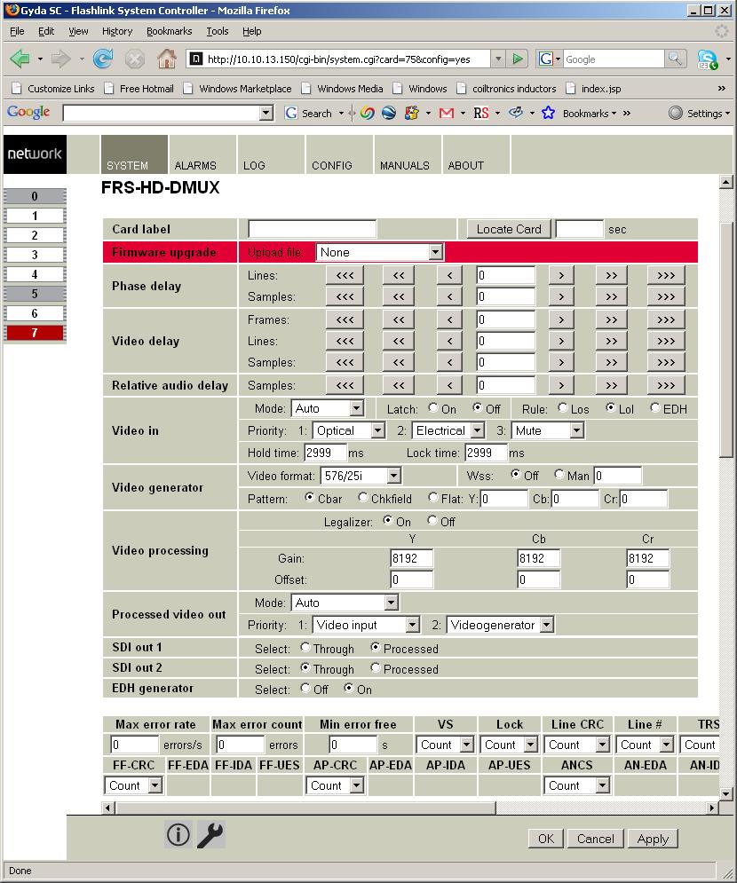
8 3.3 Optical/ Electrical input selection The FRS-HD-DMUX has both an optical (option, see Chapter 1.1) and an electrical input. The input can be chosen either by an automatic selection with priorities and rule of switching or by manual selection. This feature is only available through GYDA. Automatic selection mode In GYDA the video in mode choice is set to auto. Three input choices can be made for three priorities; optical, electrical or mute. This priority sets the order in which the card will look for a valid input. It is also possible to set a rule for when the input should be switched to the next priority. The rules are; - lol = loss of lock - los = loss of signal - EDH = Errors are found in the video Hold time and lock time can also be set for signals. This is described in Chapter De-glitcher The de-glitcher corrects timing errors within a line. The de-glitcher has a 2048 samples buffer. When the first signal is present, we call it the initial phase signal, data is taken from the centre of this buffer. If the timing reference of the video signal changes, when for instance a new source being switched into the signal path, the timing errors occurring by this change will be corrected if the new timing reference is within +/-1024 samples of the initial phase signal. This also goes for all consecutive timing references. If a signal occurs that is more than +/-1024 samples off relative to the initial phase signal, the output will repeat the last frame, refill the 2048 samples buffer and take out data from the centre of the buffer. This new signal is now considered the initial phase signal. Hence, it produces an error free video output without frame wrapping when the video input comes from a router with synchronous input video signals that all lies within +/-1024 samples of each other. 3.5 Frame synchronizer The frame synchronizer consists of a frame store buffer and some control logic. The frame store buffer can store up to 8 full HD frames. Data is fetched from this buffer according to the user settings by force of the control logic. The control logic sets the frame synchronizer into different modes dependent on the presence of a sync input Frame sync mode If a sync input (B&B or Tri-level) is present, the frame synchronizer will output a signal that has a delay relative to this signal. Two parameters can be set; "Phase delay" and "Video delay". Figure 3: Gyda view of the video delay settings Let us first focus on the phase delay, which also may be called output phase delay. This parameter can be positive or negative, and determines the relationship between the outgoing network-electronics.com 8
9 video and the sync signal. The parameter really determines a delay on an internal sync signal, isync 1. The output is synchronous with isync, see Figure 4. Figure 4: Positive phase delay Figure 4 show how the sync signal and the isync signal would look on an oscilloscope, if converted to analogue signals. The delay of isync can be given in frames, lines, and samples. The delay can be negative, see Figure 5. Figure 5: Negative phase delay The phase delay can thus be written in several ways, a large positive delay will equal a small negative delay, because there is wrap-around on a frame basis. It follows that it is not useful to specify a phase delay larger than 1 frame. Strictly speaking the range could have been limited to -1/2 frame to 1/2 frame. For convenience, the delay range is allowed to be from -1 frame samples to 1 frame 1100 samples. In order for FRS-HD-DMUX to honor the phase delay setting, it should ideally delay the incoming video between 0 to 1 frames. Because the processing delay through the card is 2 lines minimum, the actual window is between 2 lines and 1 frame + 2 lines. Hence, with the parameter (minimum) video delay set to 2 lines (the least number possible for the parameter); the output video will be between 2 lines and 1 frame + 2 lines delayed, with respect to the incoming video. A common occurrence in practical use is to synchronize an incoming video with a sync, but to let the outgoing video lead some samples or lines to the sync. This can easily be accomplished. Say that we want the outgoing video to occur 50 samples before the sync. We will then set the phase delay to -50 samples, and the video delay parameter to 2 lines. For convenience, let us assume that the incoming video is isosynchronous, but that it lags 20 lines after the sync. We will then have the situation shown in Figure 6. 1 Note that isync is not a physical entity, but a term used in this context to explain the delay process and the use of the configurable parameters related to this process. network-electronics.com 9
10 Note that the numbers in circles in the next figures are visualizing the video frames. Figure 6: Example of delayed outgoing video To match larger processing delays, one will want to first delay the incoming video, and then synchronize the video. This is equivalent to introducing a delay line for the incoming video, and then synchronize the output of the delay line with sync. In effect, one moves the delaywindow start; this is equivalent with setting of the video delay to a larger value. Let us assume that the video delay is set to 2 frames, 200 lines. In that case the outgoing video will be between 2 frames lines and 3 frames lines delayed with respect to the incoming video. For convenience, let us assume that the incoming video is isosynchronous, but that it lags 25 lines after the sync. Let us also assume that the phase delay is set to -60 samples. We will then have the situation shown in Figure 7. Figure 7: Another example of delayed outgoing video network-electronics.com 10
11 To reiterate: The phase delay can be both positive and negative and sets the difference between the phase of the sync input and the video output. The video delay sets the delay between video output and video input. However, the actual delay might be longer as it also needs to phase up to the sync input. The actual delay may be up to 1 frame longer than the minimum video delay. The user may specify a video delay between 2 lines (min) and 7 frames (max). The two parameters allow a user to delay the incoming video, and reference it to the sync input. By this mechanism, the user can precompensate processing delay in other equipment. The video delay setting simply determines a lower limit to a 1 frame wide window into a long delay line. The phase delay may be seen as a specification of the delay between the sync input, and a signal "isync". The output video is always synchronized to isync. A few more examples: Example 1: The SDI input signal is isosynchronous to a sync signal, but 12 lines, 0 samples delayed. The video delay is set to 1 frame, 0 lines and 0 samples. The phase delay is set to 65 samples. The actual delay between the input video and the output video will be 2 frames - 12 lines + 65 samples. Example 2: The SDI input signal is asynchronous to the sync signal (the frame frequency is slightly different). The video delay is set to 1 frame, 13 lines and 0 samples. The phase delay is set to -1 line. The actual delay will gradually change between 1 frame and 13 lines to 2 frames and 13 lines. The output will appear 1 line (in the output video format) ahead of the sync signal. Example 3: The SDI input signal is isosynchronous to the sync signal, but 12 lines ahead of the sync signal. The video delay is set to 1 frame, 0 lines and 0 samples. The phase delay is set to -2 lines. The actual delay between the input video and the output video will be 1 frame + 10 lines. The frames and lines are measured in units of the output SDI video standard. If the output SDI standard is 1080i25, a delay of one line is equal to 35.5us. If the output SDI standard is 720p50, a delay of one line is equal to 26.6us. If the output SDI standard is 625i25, a delay of one line is equal to 64us. For a scenario where the card receives different HD video standards, (e.g. 1080i25 and 720p50) the user may want to conserve a specific delay in microseconds for all HD video standards. This is accomplished by specifying the delay in number of samples instead of frames and lines. (For HD video standards the sample frequency is equal over standards, but the line and frame frequencies are different for the different standards). If video input disappears Given that stable SDI input and sync input exists: If the SDI input disappears, the picture will freeze for 1 second and then go to black video if the card is in the default configuration. It is possible to change the freeze time (hold time in GYDA). The black video can also be changed to color bar, check field or flat field video through Gyda. When the SDI input disappears, the Frame Delay pulses at the back plane will also disappear. If video input reappears Given stable sync input, the video will reappear after 1 second of locked video input if card is in default settings. It is possible to change the time before reappearance. This variable is labeled lock time in GYDA. network-electronics.com 11
12 If sync input disappears Given that stable SDI input and sync input exists: If the sync signal disappears, the card will act as in frame delay mode, see Chapter NOTE: This will result in a frame roll as the delay changes. If sync input reappears Given that a stable SDI input exists: If the sync signal reappears the delay mode will change back to Frame Sync mode. Hence the internal clock will be locked to the sync signal and the delay will again change. NOTE: This will result in a frame roll as the delay changes. If both signals disappears The picture will first freeze for 1 second, and then go to color bar. The output is now referenced to the local clock source. The local clock source has been synchronized with the previous seen incoming sync, and remains stable as long as operating conditions (such as temperature) does not change materially. Under stable conditions, the clock source is accurate to within 1ppm of the last sync source, but the generator is not a reference generator Frame delay mode In this mode a sync signal is not present. The delay set is then directly related to the incoming video. 1 frame and 1 line delay, means that the output will be 1 frame and 1 line delayed version of the input. If video signal disappears The picture will first freeze for 3 seconds and then go to color bar. The output is now referenced to the local clock source. However this clock source will be kept within 1 ppm of the last video source. If video signal reappears If the input video signal reappears the video will reappear on the output after 3 seconds of stable input video. The delay will be set to the same delay as before loosing input. NOTE: This may cause a frame roll. If a sync input appears Given that a stable SDI input exists: If a sync signal appears the delay mode will change to Frame Sync mode, see Chapter Hence the internal clock will be locked to the sync signal and the delay will again change. NOTE: This will result in a frame roll as the delay changes. 3.6 Video generator The video generator can produce different simple signals: Color bar, Check field and flat field. The flat field is possible to set up with all luma and chroma values. The generator may be used as the video source if there is no video signal present at either of the video inputs. The generator may also be switched on with GYDA. This will override video input but the generator signal will be locked to the input. The video standard of the generator may be set with GYDA but only if there is no video input present. network-electronics.com 12
 Chroma gain 0 32767 (0-4x, 1x = 8192) Luma offset (gain =1) -4095 4095 (-511.75 511.75 in sample values) Chroma offset (gain = 1) -2047 2047 (-255.")
13 3.7 Video processing block The video processing block consists of a gain and offset adjustment, and a video payload legalizer Gain and offset The gain and offset adjustment is done separately on the Y, Cb and Cr samples. Range Gyda Luma gain (0-4x, 1x = 8192) Chroma gain (0-4x, 1x = 8192) Luma offset (gain =1) ( in sample values) Chroma offset (gain = 1) ( in sample values) Video payload legalizer The legalizer hard clips the upper and lower limit of the video payload. With the legalizer enabled these limits are: Upper limit Luma: 3ACh Chroma: 3C0h Lower limit Luma: 040h Chroma: 040h With the legalizer disabled, the video processing block hard clips both luma and chroma to 3FBh and 004h. 3.8 EDH processing block If enabled, the EDH processing block extracts the EDH package from the video, updates the EDH flags according to SMPTE RP165 and inserts the EDH package into the ancillary data of the video. If disabled, The EDH processing block only reads, process and report the EDH package without changing it in video stream. 3.9 Video output selection The board has four outputs where two and two can be either routed directly from the reclocker or routed through the processing unit. In GYDA the direct path is labeled thru and the processing path is labeled processed Audio blocks overview Figure 8: Audio function blocks network-electronics.com 13
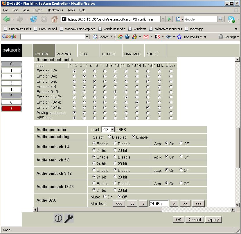
14 3.11 Audio de-embedder The Audio de-embedder extracts all audio embedded in the video stream. The de-embedder is always enabled Audio delay An audio delay relative to the video output can be specified commonly for all de-embedded channels. This is done in GYDA. The audio delay is specified in audio samples relative to the output video, and can be both positive and negative. NOTE: As the audio delay is relative to the video output it is possible to specify an audio delay that will be an actual negative delay. This will cause audio errors Audio cross point matrix The audio cross point matrix is a 10x10 cross point with inputs and outputs as shown in Figure 8. The 8 de-embedded channels, a 1 khz sine and black sound are selectable inputs. Black sound is explained in Chapter 3.1. The outputs of the cross points are 8 stereo channels for re-embedding, one analog audio output and one AES output. All outputs have fallback options that can be set in GYDA. The priorities can be selected between matrix (being the choice in the cross point matrix), sine or black Audio generator The stereo audio generator is available in the audio cross point matrix as a source. It is a high purity 1 khz sine wave with a 250ms interruption on the left channel every 3 seconds. The audio level may be set to one of two standards. The two levels are -18 dbfs and -20 dbfs. These two levels correspond to EBU R68 and SMPTE RP Audio processing block The output of each stereo signal from the audio cross point matrix may be manipulated in the audio processing block (LL, RR, RL,!LR, L!R, (L+R)/2, MS) This is controlled with the GYDA controller. The stereo signals may be output in one of the following ways: - LR, Left / Right No change. - LL, Left/ Left Left channel is copied into the right channel. - RR, Right/ Right Right channel is copied into the left channel. - RL, Right/ Left Channels are swapped. -!LR, ØLeft/ Right The left channel is phase inverted. - L!R, Left/ ØRight The right channel is phase inverted. - (L + R)/2 The left and right channels are summed. - MS The left and right channels are converted from AB stereo to MS stereo. The sum products ((L+R)/2 and MS) are reduced in level by 6 db to avoid any possibility of clipping Audio embedder The audio embedder can be enabled per group in GYDA. When a group is disabled the audio inside that group is removed. When in SD mode, a 24bit sound signal can be changed to 20bit through GYDA control. This removes the 4 least significant bits of the signal. The audio control package is left unchanged as the bit range is still present. network-electronics.com 14
15 The audio control package can also be switched on and off in SD mode through GYDA control. The audio embedder can be switched off all together. In this state the audio embedded on the input signal is left unchanged Analog audio output The level of the analog audio output can be adjusted in GYDA. The minimum step is 0.5dB and the range is from -95.5dBu to 24dBu. It is also possible to mute the output totally. network-electronics.com 15
16 4 Configuration The board can be configured both manually and through the Network control system GYDA. However, only a few of the configurable parameters are available when operating in manual mode. 4.1 Manual mode To reach manual mode DIP16 labeled OVR on the board must be switched on (to the right) and the board must be re-booted. This takes the board out of GYDA control (if it was previously set to off) and onto being controlled by the DIP switch and rotary switch settings. Settings not controlled by any of these switches are set to settings from previous settings (factory setup or GYDA setup). The Manual Mode configuration controls are all found on the front side of the board. There are two sets of DIP switches, one rotary switch and two push buttons. On the bottom side of the card, three slide switches can also be found, but they are hardware switches that are set for all operation modes. Figure 9: The figure shows a top view component printout of the board. Note the location of LEDs, push-buttons, the rotary switch and the 2 sets of DIP-switches DIP switch functions The two sets of DIP switches are labeled with a number running from 1 to 15. The 16 th DIP is labeled OVR. Note that the left DIP switch of the horizontal DIP package is number 1. The top DIP switch of the vertical DIP package is number 9. Table 1: DIP SWITCH FUNCTIONS Switch # Function name Function DIPs Comment 1-2 ADAC group DIP[1 2] = [Off Off] => Emb grp 0 DIP[1 2] = [Off On] => Emb grp 1 DIP[1 2] = [On Off] => Emb grp 2 DIP[1 2] = [On On] => Emb grp 3 3 ADAC ch1/ch2 Off = ch1, On = ch2 (of group selected from DIP1&2) 4-5 AES group DIP[4 5] = [Off Off] => Emb grp 0 DIP[4 5] = [Off On] => Emb grp 1 DIP[4 5] = [On Off] => Emb grp 2 These 3 DIPS routes one embedded AES channel to the Analog Audio output These 3 DIPS routes one embedded AES network-electronics.com 16
17 Switch # Function name Function DIPs Comment DIP[4 5] = [On On] => Emb grp 3 6 AES channel Off = ch1, On = ch2 (of group selected from DIP4&5) 7 Emb. enable Off: No audio embedded On: Audio embedded 8 Dlink/ AES Off: Data link on AES output. On: AES on AES output Frame delay DIP[ ] = [Off Off Off] => 0 frms DIP[ ] = [Off Off On] => 1 frms DIP[ ] = [Off On Off] => 2 frms DIP[ ] = [Off On On] => 3 frms DIP[ ] = [On Off Off] => 4 frms DIP[ ] = [On Off On] => 5 frms DIP[ ] = [On On Off] => 6 frms DIP[ ] = [On On On] => 7 frms 12 SDI OUT 1 Off: through mode On: processed mode 13 SDI OUT 2 Off: through mode On: processed mode 14 Video Generator Off: Color bar On: Black field 15 RESET Off: Use values preset by GYDA. On: RESET to factory defaults channel to the AES output When off, the audio is left untouched on the SDI stream. When on, the audio configured to be embedded is embedded into the SDI. With Data link selected, note that the two slide switches on the bottom side must be switched. With a sync-input present, this sets the minimum frames delay. Without a syncinput present this sets the no. of frames delay relative to the input. In through mode the video only goes through a reclocker. In through mode the video only goes through a reclocker. This is the video generator signal that is shown when video is detected lost according to the fallback rule set in GYDA. This DIP is only read at power up. After repowering with the DIP off, the board must be kept in the frame for minimum 10s to fully reset. Values preset by GYDA, are only values not set by network-electronics.com 17
18 Switch # Function name Function DIPs Comment DIPs, push buttons or rotary switches. 16 OVR Off: GYDA mode On: Manual mode This DIP is only read at power up. OVR is short term for GYDA override FACTORY reset function The factory reset is done by setting DIP 15 to On and power up the card. The inputs (optical, electrical video and sync) should be removed. Then, pull out the card, put DIP 15 to Off and power up the card again. The card will now reset. The board must be under power for at least 10 seconds for all the values to reset Rotary switch and push buttons The rotary switch, labeled DLY, adjusts the phase delay by -5 to +4 video lines. It is only functional when a sync signal, black & burst or tri-level, is present at the sync input. The rotary switch is accessible from the board front. The push buttons, labeled INC and DEC, are used to fine adjust the phase delay by samples. It can adjust +/- ½ video lines for the present video standard. Figure 10: The figure shows a bottom view component printout of the board. Note the location of the slide-switches Slide switches The two switches at the top of Figure 10 switch between AES out and Data out. It DC couples the output signal when in DATA out mode, and AC couples the signal when in AES mode. Note that it is also necessary to enable the data output on DIP8 (=Off), or in GYDA to output embedded data. Switches moved to the right routes out AES. The switch on the left card edge switches between backplane sync input and Flashlink distributed sync (Future feature upgrade of Flashlink frame). Switch moved up routes the backplane sync to the card. network-electronics.com 18
19 4.2 GYDA mode All functions of the card can be controlled through the GYDA control system. The GYDA has an information page and a configuration page Information page The information page shows a dynamic block-diagram of the board and some additional information text. The block diagram updates with the boards status, showing input signal selected, signals missing (by red crosses over signal lines) and routing through switches. It also shows the audio matrix selections that have been made in the configuration page. Note that if embedded audio is missing in groups the user will still be allowed to select the input in the matrix, but the output will go to a fallback position. This will be shown in the block-diagram only with a red cross over the input line to the matrix. The text on the information page gives information about functionality not displayed on the dynamic block diagram. The video delay represents the actual delay between input and output video. The audio de-embedder 1-4 shows the state of the audio control package for the embedded audio on the input signal. The audio embedder 1-4 shows the state of the audio control package and the bit depth for the embedded audio on the output signal. Embedded uart shows the data rate of data embedded in the audio control package on the incoming signal Configuration page The different configuration possibilities are explained in detail in Chapter 3, under the corresponding functions. network-electronics.com 19

20 Figure 11: GYDA information page network-electronics.com 20
21 network-electronics.com 21
22 network-electronics.com 22
 network-electronics.")
23 Figure 12: Configuration page (3 screen dumps at different positions on the page) network-electronics.com 23
24 5 Connections Figure 13: FRS-HD-DMUX-C1 (this is rev.2 of the backplane) The backplane for the FRS-HD-DMUX is labeled FRS-HD-DMUX-C1. The table below shows the connectors and their functions. It is important to terminate the sync input. The backplane opens for looping the sync. It is then necessary to terminate the last board in the loop. On boards of revision 2 or later this can be done either by setting the slide switch position to ON (on backplane) or by adding a 75R terminator to one of the sync input. On boards of revision 1 termination is done by adding a 75R terminator to one of the sync inputs. Function Label Connector type HD/SD-SDI input IN BNC HD/SD-SDI output 1 1 BNC HD/SD-SDI output 1 inverted BNC 1 HD/SD-SDI output 2 2 BNC HD/SD-SDI output 2 inverted BNC 2 Sync input SYNC BNC Sync input (Termination or loopthru) SYNC BNC Analog audio out left channel AA.OUT WECO Audio connector network-electronics.com 24
25 Analog audio out left channel L AA.OUT R Positive GND Negative WECO Audio connector Positive GND Negative GPI out 1-3 No label TP45 pin 1, 2,3 (8 = GND) AES out No label TP45 pin 4, 5, 6 Frame delay pulse No label TP45 pin 7 (8=GND) Optical input No label BSC-II (for SC input) network-electronics.com 25
26 6 Operation 6.1 Front panel LED indicators Diode \ state Red LED Orange LED Green LED No light Card status PTC fuse has been triggered or FPGA programming has failed Module has not been programmed or RESET and OVR Module is OK Module has no power SDI input status Sync input status Audio input status Video signal absent. Sync signal absent No audio embedded in incoming video DIPS are on. Video signal present but card not able to lock VCXO Sync signal present but card unable to lock VCXO One, two or three audio groups embedded in incoming video Video input signal in lock B&B or Trilevel sync in lock 4 audio groups embedded in incoming video Module has not been programmed Module has not been programmed Module has not been programmed 6.2 GPI alarms Only three alarms are present on the RJ45 connector as two pins are used for the AES/ RS422 data port and one pin is used for Frame delay pulse signal. The three alarms are: - Status error - Video signal lost - Black and burst lost An active alarm condition means that the transistor is conducting. 6.3 GPI/ AES/ Data connections 8pin modular jack Pin number Description 1 Status error 2 SDI input lost 3 Black & Burst lost 4 AES+/RS Ground 6 AES-/RS422-7 Frame delay 8 Ground Figure 14: GPI pin layout network-electronics.com 26
27 6.4 RS422 commands FLP4.0 required commands Block Blk # Commands Example Response Control - -?? product name\ SW rev n.m\ FW rev r.s\ protocol ver 4.0\ Hello command. Note 1: No other commands will be available until the card has received this hello. Note 2: This command will also enable checksums. Note 3: Cards are designed to be hotswappable. To sync with the start of a new command, the cards will wait for a <lf> character before looking for a valid command. conf 0 - conf 0 *too long to list* Configuration settings Retrieves the card's configurable settings. Each addressable block is represented by a single line. Dynamic status may be included in response, but is usually reported in info only. - - info info *too long to list* Dynamic status info Blocks with static settings only will usually not be included, see conf above. - - chk off chk off ok Checksum off If issued twice in succession, this command will disable checksums. Note: Responses will still have the checksums appended. NOTE1:? command turns the checksum on again - - locate on <seconds> locate off locate on 3 locate off ok Card locator This command will cause all the LEDs to flash for a user specified number of seconds. If omitted, the value <seconds> will be set to a default of 120 seconds. The flashing can be terminated at any time with locate off. - - address address address <address> Card address This command will check and update the card's current rack and slot address, which is normally only done at start-up. - - filename filename frshddmux ffw filename frshddmux mfw <name>'.'<extension > Firmware update The <name> part must match the card's hardware and include a revision number, and the extension must be either 'ffw' for FPGA firmware or 'mfw' for microcontroller firmware. After running this command the board will wait for the firmware in Intel-hex format. - - fin fin ok Finalize Finalize the programming of the microcontroller. See description of the uc bootloader (separate document). misc 0 - NOT AVAILABLE BY COMMAND. ONLY FOUND in Conf 0 prog fin ' ' ovr Misc info prog if the card is freshly programmed by the bootloader and the program is still un-finalized. fin is the normal condition. ovr if DIP-switch 16 is set to the ON position and the card is under DIP-switch network-electronics.com 27
28 6.4.2 Normal control blocks Block Blk # control. Note 1: The info part of misc has additional functionality when locate is used: locating <remaining seconds>. This enables a visible countdown clock in Gyda, but is not a required part of FLP400. Commands Example Response Control pin 0 on off pin 0 on pin 0 off cd ncd Pin diode for optical input. No control; only used to report carry detect or not carry detect. ceq 0 - ceq 0 cd ncd Cable equalizer for electrical input. No control; only used to report carry detect or not carry detect. cho 0 pri <k> pri <k> <l> pri <k> <l> <m> pos man <k> pos auto latch on latch off latch reset rule lol rule los rule trse t1 <hold_time> t2 <lock_time> cho 0 pri 0 cho pri 0 1 cho pri 10 2 cho 0 pos man 1 cho 0 pos auto cho 0 latch on cho 0 latch off cho 0 latch reset cho 0 rule lol cho 0 rule los cho 0 rule trse cho 0 t size 3 pri k,l,m auto latch <latch_status> t1 <hold time> t2 <lock time> <rule> size 3 pri k,l,m man m latch <latch_status> t1 <hold time> t2 <lock time> <rule> Video input select pri: a prioritized list of inputs, used when change-over is automatic. The list can have 1, 2 or 3 entries, or levels. Manual mode is effectively the same as automatic mode with one priority level only, but has its own command. 0 = from optical input 1 = from electrical input 2 = generator (from cho 1) latch: <latch_status> can be either on or off and selects if the change-over is latching or not, used when change-over is automatic. Latch on means that if we've lost our main source and moved on to a lower priority level, we'll not search to see if the higher pri s will reappear. cho 0 t rule: <rule> can be either los, lol or trse, which means loss off signal, loss of lock, and timing reference signal error. This determines what triggers an automatic change-over. t1 and t2: change-over doesn't happen immediately, as a precaution against glitches and unstable signals. The timers t1 and t2 let the user decide how long (in ms) we will cling on to a missing input before we consider it gone and move on to the next pri level, and how long an input with a higher priority should be present before we consider it repaired and switch back, respectively. Note 1: the latch setting only applies to rule los. Note 2: the card change back to physical inputs from generators regardless of latch setting. As a side note, this means that t2 is important even when rule=lol and/or latch is on. Note 3: If we have selected rule=lol and a 3-level pri list with two physical inputs on top and a generator at the bottom and network-electronics.com 28
29 we're in generator mode (lost both physical inputs) and both physical inputs reappear at more or less the same time, which physical input will be chosen is unpredictable. This again due to having one reclocker only and having to hunt for a valid input in the background while the generator is still selected. cho 1 pri <k> pri <k> <l> pos man <k> pos auto cho 1 pri 0 cho 1 pri 0 1 cho 1 pos man 1 size 3 pri k,l auto size 3 pri k,l man m Video fallback setting Second video change-over. This cho is a slave of cho 0, in the sense that it has no latch, t1, t2 or rule settings of its own. It has a generator input that must be set up separately and that allows a switch to an internal video generator. 0 = from cho 0 1 = from video generator, vgen 0 2 = kill cho 2-11 pri <k> pri <k> <l> cho 12 pri <k> pri <k> <l> cho 2 pri 1 cho 5 pri 0 2 cho 12 pri 1 cho 12 pri 0 2 cho 13 pos man <k> cho 13 pos man 0 cho 13 pos man 1 cho 14 pos man <k> cho 14 pos man 0 cho 14 pos man 1 cho 15 pos man <k> cho 15 pos man 0 cho 15 pos man 1 cho 16 pos man <k> cho 16 pos man 0 cho 16 pos man 1 cho 17 pos man <k> cho 17 pos man 0 cho 17 pos man 1 size 4 pri k,l size 4 pri k,l size 2 man k size 2 man k size 2 man k size 2 man k size 2 man k Note: manual mode is the same as automatic mode with a priority list with only one priority level. Audio fallback setting Audio change-over blocks, one cho per audio output from the audio matrix, mtx 0. No other settings but the priority list. 0 = from audio matrix 1 = sine 2 = black 3 = kill Note: Only generators (pri 1, 2 or 3) are allowed to be set as first and only priority. Audio common fallback setting A short-cut to set change-overs 2-11 all at once. Will of course not report anything in info, that's left to the individual cho blocks. AES output select This cho has only manual mode and works as a simple 2:1 switch. 0: AES is selected 1: Embedded UART is selected EDH insert select This cho has only manual mode and works as a simple 2:1 switch. 0: EDH off 1: EDH on SDO 0 output select This cho has only manual mode and works as a simple 2:1 switch. 0: Through mode (re-clocked only) 1: Processed mode (SDI from FPGA SDO 1 output select This cho has only manual mode and works as a simple 2:1 switch. 0: Through mode (re-clocked only) 1: Processed mode (SDI from FPGA Audio embedding enable This cho has only manual mode and works as a simple 2:1 switch. 0: embedding off (Audio embedded on network-electronics.com 29
30 input signal left untouched) 1: Embedding on rcl 0 - rcl 0 lock lol Reclocker. No control; only used to report lock status. emb 0-3 en dis acp ( on off ) use24 ( on off ) del (off (on <del12> <del34>)) demb demb 0 demb 2 vprc 0 lglz on lglz off (y cb cr) <gain> <offset> emb 0 en emb 2 dis emb 1 acp on emb 3 acp off emb 1 use24 on emb 2 use24 off emb 0 del off emb 2 del on vprc 0 lglz on vprc 0 lglz off vprc 0 y vprc 0 cb vprc 0 cr (en dis) use24 (on off) acp (on off) del (off (on <del12> <del34>)) grp k en sync 0 - sync 0 'lol' ('lock' ('trilvl' 'bb' 'sdi') ) dly 0 <frames>frms <lines>lines <samples>sps dly 0 2frms dly 0 2lines 30sps dly 0 0frms 50sps dly 0 0frms 3lines 50sps 'tgt' <frames> frms <lines> lines <samples> sps dly 1 <audio_samples>sps dly 1-30sps 'tgt' <audio_samples> sps dly 2 <lines>lines <samples>sps vgen 0 cbar chkfield white yellow cyan dly 2 1lines -30sps vgen 0 cbar 'phase' <lines> lines <samples> sps video <lns>/<rate><scan> wss ( auto off ( on <wss_value> ) ) (cbar chkfield white Audio embedder block en/dis: Enables or disables the embedding of the group into the ancillary area. acp on/off: This is valid only for SD and enables the audio control package. use24 on/off: This is only valid for SD and selects between 24bit and 20bit sound. del off/on delay12 delay34: For each of the embedder groups the delay bits for ch1+2 and for ch3+4 can be inserted into the ACP. The delay value can be positive and negative and is put directly into the ACP as it is written. Note: To set both delays to 0 would be the same as turning the delays off. The response reflects this. Audio de-embedders One permanently assigned to each incoming group, always enabled. No control available. Video processing block Gain and offset are both signed fixed point numbers. Gain is in 2.13-format, while offset for Y and the chroma channels are given in 10.2 and 9.2 respectively. Gain range is , Gain =0x = 0, Gain =1x = 8192, Gain =4x = Luma Offset range is , Offset =0 = 0 Chroma Offset range is , Offset =0 = 0 Frequency reference for video output. Status only, no commands available. Video delay This sets the minimum video delay of the card. In info this block reports back the current delay in nanoseconds. This will vary with the incoming video standard. audio delay The audio delay is given in audio samples. Audio delay is always given relative to video. Video phase If lines!= 0 the resulting phase will vary with incoming video standard, see dly 0 above. Internal video generator. The video generator will be activated in two different ways: If selected as a fallback option the generator will generate the selected pattern when the network-electronics.com 30
31 green magenta red blue black flat <Y> <Cb> <Cr> video <lns>/<rate><scan> wss (auto off (on <wss_val>) ) edh 0 msk <24b_mask> reset mtx 0 <i1> <o1>...<in> <on> <i1> <o1>,<o2>,...<on> <i1> <o1> - <o2>..or the above combined vgen 0 flat vgen 0 video 1080/24p vgen 0 video 1080/25p vgen 0 video 1080/25i vgen 0 video 1080/29i vgen 0 video 1080/30i vgen 0 video 720/24p vgen 0 video 720/25p vgen 0 video 720/29p vgen 0 video 720/30p vgen 0 wss auto vgen 0 wss on 7 edh 0 msk 0xFE0005 edh 0 reset mtx mtx 0 0 0, 1 1, 2 2 mtx mtx agen 0 lvl <sine_level>cbfs agen lvl -180 agen lvl -200 aprc 0-9 lr rl ll rr nlr lnr mm ms ablk 0 mute ( on off ) lvl <level> aprc 0 lr aprc 3 ll aprc 9 mm ablk 0 mute on ablk 0 mute off ablk 0 lvl -500 ablk 0 lvl 30 yellow cyan green magenta red blue black (flat <Y> <Cb> <Cr>) ) msk <24b_mask> other input(s) are missing, and then use the video settings from the last external source present. It can also be selected as the main input in cho 1, in which case its own video settings will also be used. Error detection and handling Error counting. The count itself is reported in info. Errors can be masked off and not counted; this is the purpose of the mask. The counter itself is 16b and will wrap around, but can also be reset by issuing reset. size M:N i1 i2 i3... in Audio matrix mtx 0 (size 10:10) controls the audio matrix; outputs 0-7 are embedded sound, 8=adac and 9=AES. Note: Any combination of the three basic commands are allowed, for instance the following command to set up a 10x10 audio matrix in a single line: mtx ,3-9 => mtx 3 size 10: sine 1kHz lvl <sine_level>cbfs lr rl ll rr nlr lnr mm ms dac lvl <level>cbu mute <mute_status> Audio generator The amplitude of the generated sine that can be chosen as fallback in audio change-overs. Legal values are -180cBFS or -200cBFS (centibel referred to full scale output). Units are optional, but if included must be written as cbfs (case sensitive). Audio processing One block for each output from cho Outputs 8+9 are adac and AES, the lower 8 are routed to the embedder. The meaning of the commands are as follows: lr = Normal rl = Channel swapped ll = Left channel to both output channels rr = Right channel to both output channels nlr = Left channel phase inverted lnr = Right channel phase inverted mm = Mono, both channels = (r+l)/2 ms = Mono/stereo, m=(l+r)/2, s=(l-r)/2 Audio DAC control This word dac identifies this audio block as a DAC. The outputs can be muted, <mute_status> given as on or off, and the output level can be set in cbu (tenth dbu). Units are optional, if included must be written as cbu (case sensitive). Note 1: The lvl and mute are independent, so that the card will remember the lvl setting (and change lvl setting) while muted. network-electronics.com 31
32 Note 2: The resolution of the lvl control is 0.5dB but the card will perform correct rounding to nearest legal value and report the resulting setting. Legal input range is [-957cBu, 247cBu], representing the range [-95.5dBu, 24.5dBu]. uart 0 - tx The embedded data link, selectable by cho 13. No control possible, the word tx indicates that this is a transceiver only. Uart info reports link status: los (loss of signal), raw, or the speed of the embedded link (example: /8/n/1) Commands intended for debug/lab use only Block Blk # Commands example Response Control spi - on off spi on spi off spi off used to isolate the uc from the SPI lines during programming of the flash by external programmer. spi on must be issued in order to re-enable normal card operation with the uc as the SPI master. spir - <address> spir 0x0004 Read a single word (or byte) from a SPI registers. Addressing is 16b and most significant nibble determines which chip. These are the address ranges: 0x0000 0x0fff : audio DAC 0x1000 0x1fff : FPGA 0x2000 0x2fff : flash 0x3000 0x3fff : deserializer 0x4000 0x4fff : serializer 0x5000 0x5fff : shift register (for LEDs) 0x6000 0x7fff : Not in use on this module. spiw - <address> <data> spiw 0x0004 0x2c With the same address ranges as for spir above, this command allows the user to modify SPI registers. thebug - - thebug A collection of debug information that is presented in a Gyda block-like format. First line tells which image is currently loaded. Second line contains the filename and version of the uc software, including the AVR controller it was compiled for. The third line contains the SW flags in uc, the number of times the watchdog timr has kicked in, readout of dipswitches, input select for deserializer, SDOn on/off, slew rates, and status for the video changeovers. The next two lines contain raster information from the deserializer and serializer respectively, while the last two lines contain sample values for mlines and VCXO. network-electronics.com 32
33 General environmental requirements for Network Electronics equipment 1. The equipment will meet the guaranteed performance specification under the following environmental conditions: - Operating room temperature range: 0 C to 45 C - Operating relative humidity range: <90% (non-condensing) 2. The equipment will operate without damage under the following environmental conditions: - Temperature range: -10 C to 55 C - Relative humidity range: <95% (non-condensing) network-electronics.com 33
34 Product Warranty The warranty terms and conditions for the product(s) covered by this manual follow the General Sales Conditions by Network Electronics ASA. These conditions are available on the company web site of Network Electronics ASA: network-electronics.com 34

35 Appendix A Materials declaration and recycling information A.1 Materials declaration For product sold into China after 1st March 2007, we comply with the Administrative Measure on the Control of Pollution by Electronic Information Products. In the first stage of this legislation, content of six hazardous materials has to be declared. The table below shows the required information. Toxic or hazardous substances and elements 組成名稱 Part Name 鉛 Lead (Pb) 汞 Mercury (Hg) 镉 Cadmium (Cd) 六价铬 Hexavalent Chromium (Cr(VI)) 多溴联苯 Polybrominated biphenyls (PBB) 多溴二苯醚 Polybrominated diphenyl ethers (PBDE) FRS-HD-DMUX O O O O O O <Power supply, if delivered with unit> O O O O O O O: Indicates that this toxic or hazardous substance contained in all of the homogeneous materials for this part is below the limit requirement in SJ/T X: Indicates that this toxic or hazardous substance contained in at least one of the homogeneous materials used for this part is above the limit requirement in SJ/T This is indicated by the product marking: A.2 Recycling information Network Electronics provides assistance to customers and recyclers through our web site Please contact Network Electronics Customer Support for assistance with recycling if this site does not show the information you require. Where it is not possible to return the product to Network Electronics or its agents for recycling, the following general information may be of assistance: Before attempting disassembly, ensure the product is completely disconnected from power and signal connections. All major parts are marked or labeled to show their material content. Depending on the date of manufacture, this product may contain lead in solder. Some circuit boards may contain battery-backed memory devices. network-electronics.com 35
 Network Electronics ASA P.B.")
36 EC Declaration of Conformity MANUFACTURER AUTHORISED REPRESENTATIVE (Established within the EEA) MODEL NUMBER(S) DESCRIPTION DIRECTIVES this equipment complies with HARMONISED STANDARDS applied in order to verify compliance with Directive(s) Network Electronics ASA P.B. 1020, N-3204 SANDEFJORD, Norway Not applicable FRS-HD-DMUX HD-SDI Frame Synchronizer with audio de-embedding LVD 73/23/EEC EMC 2004/108/EEC EN :1996 EN :1996 TEST REPORTS ISSUED BY Notified/Competent Body Report no: Nemko E TECHNICAL CONSTRUCTION FILE NO Not applicable YEAR WHICH THE CE-MARK WAS AFFIXED 2008 TEST AUTHORIZED SIGNATORY MANUFACTURER AUTHORISED REPRESENTATIVE (Established within EEA) Date of Issue Not applicable Place of Issue Sandefjord, Norway Name Position Thomas Øhrbom Quality Manager (authorized signature)
PGM-HD-2x1-PB. User manual. HD/SD-SDI 2x1 Program Switch with Frame Synchronizer. Rev. B
 HD/SD-SDI 2x1 Program Switch with Frame Synchronizer User manual Nevion Nordre Kullerød 1 3241 Sandefjord Norway Tel: +47 33 48 99 99 nevion.com Nevion Support Nevion Europe P.O. Box 1020 3204 Sandefjord,
FRS-HD-CHO / FRS-HD-CHO-ASI / ASI-CHO-2x1-PB
 / FRS-HD-CHO-ASI / ASI-CHO-2x1-PB HD/SD-SDI 2x1 Change-Over with Frame Synchronizer and/or ASI 2x1 Change-Over User manual Nevion Nordre Kullerød 1 3241 Sandefjord Norway Tel: +47 33 48 99 99 nevion.com
ARC-SD-XMUX4. User manual. SD-SDI Aspect Ratio Converter with 4x AES I/O. Rev. B
 SD-SDI Aspect Ratio Converter with 4x AES I/O User manual Nevion Nordre Kullerød 1 3241 Sandefjord Norway Tel: +47 33 48 99 99 nevion.com Nevion Support Nevion Europe P.O. Box 1020 3204 Sandefjord, Norway
FRS-3G-DUAL. User manual. Dual Frame Synchronizer for 3G/HD/SD-SDI. Rev. A (Preliminary)
") Dual Frame Synchronizer for 3G/HD/SD-SDI User manual Nevion Nordre Kullerød 1 3241 Sandefjord Norway Tel: +47 33 48 99 99 nevion.com Nevion Support Nevion Europe P.O. Box 1020 3204 Sandefjord, Norway Support
Dual Frame Synchronizer for 3G/HD/SD-SDI User manual Nevion Nordre Kullerød 1 3241 Sandefjord Norway Tel: +47 33 48 99 99 nevion.com Nevion Support Nevion Europe P.O. Box 1020 3204 Sandefjord, Norway Support
User Manual AES-MUX. Multichannel digital audio to fibre.
 User Manual AES-MUX Multichannel digital audio to fibre. Network Electronics ASA Thorøya Sandefjord, Norway Phone: +47 33 48 99 99 Fax: +47 33 48 99 98 e-mail: support@network-electronics.com www.network-electronics.com
AV-3G-XMUX User Manual
 AV-3G-XMUX User Manual Revision: B 2015-04-07 nevion.com Contents 1 Nevion Support 5 2 Revision History 6 3 Product Overview 7 3.1 Summary 7 4 Introduction 8 4.1 Extra 3G functions 8 4.1.1 Large mode 8
AAV-HD-DMUX(-R)/ AAV-SD-DMUX(-R)
/ AAV-SD-DMUX(-R)") AAV-HD-DMUX(-R)/ AAV-SD-DMUX(-R) HD/SD analog / digital audio de-embedder User manual Rev. 7 Nevion Europe AS P.O. Box 1020, 3204 Sandefjord, Norway Tel: +47 33 48 99 99 Fax: +47 33 48 99 98 www.nevion.com
AAV-HD-DMUX(-R)/ AAV-SD-DMUX(-R) HD/SD analog / digital audio de-embedder User manual Rev. 7 Nevion Europe AS P.O. Box 1020, 3204 Sandefjord, Norway Tel: +47 33 48 99 99 Fax: +47 33 48 99 98 www.nevion.com
UDC-3G-XMUX4+ User manual. 3G/HD/SD-SDI Format and Standard converter with Frame Synchronizer and 4x AES I/O. Rev. D
 3G/HD/SD-SDI Format and Standard converter with Frame Synchronizer and 4x AES I/O User manual Nevion Nordre Kullerød 1 3241 Sandefjord Norway Tel: +47 33 48 99 99 nevion.com Nevion Support Nevion Europe
AAV-HD-XMUX(-T/R)/ AAV-SD-XMUX(-T/R)
/ AAV-SD-XMUX(-T/R)") AAV-HD-XMUX(-T/R)/ AAV-SD-XMUX(-T/R) HD/SD analog/digital audio embedder User manual Nevion Nordre Kullerød 1 3241 Sandefjord Norway Tel: +47 33 48 99 99 nevion.com nevion.com 2 Nevion Europe Nevion Support
AAV-HD-XMUX(-T/R)/ AAV-SD-XMUX(-T/R) HD/SD analog/digital audio embedder User manual Nevion Nordre Kullerød 1 3241 Sandefjord Norway Tel: +47 33 48 99 99 nevion.com nevion.com 2 Nevion Europe Nevion Support
HDSDI-CHO-2x1 HD-SDI-CHO-2x1-PB
 HD-SDI-CHO-2x1-PB HD-SDI Change-over 2x1 User manual Nevion Nordre Kullerød 1 3241 Sandefjord Norway Tel: +47 33 48 99 99 nevion.com Nevion Support Nevion Europe P.O. Box 1020 3204 Sandefjord, Norway Support
3GHD-OE 3GHD-OE-2. User manual. Single and dual 3G-SDI optical to electrical converter. Rev. F
 3GHD-OE 3GHD-OE-2 Single and dual 3G-SDI optical to electrical converter User manual Nevion Nordre Kullerød 1 3241 Sandefjord Norway Tel: +47 33 48 99 99 nevion.com Nevion Support Nevion Europe P.O. Box
3GHD-EO-SFP. User manual. SD/HD/3G-SDI electrical to optical converter with SFP. Rev. A
 SD/HD/3G-SDI electrical to optical converter with SFP User manual Nevion Nordre Kullerød 1 3241 Sandefjord Norway Tel: +47 33 48 99 99 nevion.com Nevion Support Nevion Europe P.O. Box 1020 3204 Sandefjord,
IQDEC01. Composite Decoder, Synchronizer, Audio Embedder with Noise Reduction - 12 bit. Does this module suit your application?
 The IQDEC01 provides a complete analog front-end with 12-bit composite decoding, synchronization and analog audio ingest in one compact module. It is ideal for providing the bridge between analog legacy
Part 2. LV5333 LV5381 LV5382 LV7390 LV7770 LV7330 LV5838 LT4610 LT4600 LT4446 LT4100 LT4110 Accessories
 Part 2 LV5333 LV5381 LV5382 LV7390 LV7770 LV7330 LV5838 LT4610 LT4600 LT4446 LT4100 LT4110 Accessories LT4610SER01 OPTION LTC IN/OUT GPS IN CW IN AES/EBU/OUT SILENCE OUT WCLK OUT ETHERNET GENLOCK
HDB
 GDB990-950-900-550-500 HDB990-950-900-550-500 3Gb/s, HD, SD digital or analog audio de-embedder with TWINS dual A Synapse product COPYRIGHT 2012 AXON DIGITAL DESIGN BV ALL RIGHTS RESERVED NO PART OF THIS
3GHD-EO-2-SFP. User manual. Dual SD/HD/3G-SDI electrical to optical converter with SFP. Rev. C
 Dual SD/HD/3G-SDI electrical to optical converter with SFP User manual Nevion Nordre Kullerød 324 Sandefjord Norway Tel: +47 33 4 99 99 nevion.com Nevion Support Nevion Europe P.O. Box 020 3204 Sandefjord,
SD-SDI LINE SYNCHRONIZER
 Flashlink User Manual LIS-SDI SD-SDI LINE SYNCHRONIZER network-electronics.com Rev. 3 Revision history The latest version is always available in pdf-format on our website: http://www.network-electronics.com/
AV-HD-XMUX (-T/R) / AV-SD-XMUX (-T/R)
 / AV-SD-XMUX (-T/R)") AV-HD-XMUX (-T/R) / AV-SD-XMUX (-T/R) HD/SD digital audio embedders and de-embedders User manual Nevion Nordre Kullerød 1 3241 Sandefjord Norway Tel: +47 33 48 99 99 nevion.com Nevion Support Nevion Europe
AV-HD-XMUX (-T/R) / AV-SD-XMUX (-T/R) HD/SD digital audio embedders and de-embedders User manual Nevion Nordre Kullerød 1 3241 Sandefjord Norway Tel: +47 33 48 99 99 nevion.com Nevion Support Nevion Europe
CEDAR Series. To learn more about Ogden CEDAR series signal processing platform and modular products, please visit
 CEDAR Series The CEDAR platform has been designed to address the requirements of numerous signal processing modules. Easily-installed components simplify maintenance and upgrade. To learn more about Ogden
3G-IP-MUX-8-SFP. User manual. 8 channel bi-directional 3G/HD/SD Video over IP multiplexer/de-multiplexer. Rev. A
 8 channel bi-directional 3G/HD/SD Video over IP multiplexer/de-multiplexer User manual Nevion Nordre Kullerød 1 3241 Sandefjord Norway Tel: +47 33 48 99 99 nevion.com Nevion Support Nevion Europe P.O.
3Gb/s, HD, SD 16ch digital audio embedder with embedded domain audio shuffler, mixer and framesync COPYRIGHT 2018 AXON DIGITAL DESIGN BV
 3Gb/s, HD, SD 16ch digital audio embedder with embedded domain audio shuffler, mixer and framesync A Synapse product COPYRIGHT 2018 AXON DIGITAL DESIGN BV ALL RIGHTS RESERVED NO PART OF THIS DOCUMENT MAY
3GHD-CHO-2x4/2x3. User manual
 3GHD-CHO-2x4/2x3 Multi Rate 3GHD-SDI Distribution Amplifier with change-over User manual Rev. 2 Nevion HQ: Nevion Europe, P.O. Box 1020, 3204 Sandefjord, Norway Tel: +47 33 48 99 99 Fax: +47 33 48 99 98
FLEX Series. Small-Scale Routing Switcher. KEY FEATURES AND BENEFITS Frame and signal. Flexible control. Communication and control.
 CE FLEX series features high performance and compact structure. Mix of different signal formats (CVBS, AUDIO, 3G/HD/SD-SDI, DVB-ASI, HDMI and VGA) is allowed in a single frame. Switching sizes can be customized
C8491 C8000 1/17. digital audio modular processing system. 3G/HD/SD-SDI DSP 4/8/16 audio channels. features. block diagram
 features 4 / 8 / 16 channel LevelMagic2 SDI-DSP with level or loudness (ITU-BS.1770-1/ ITU-BS.1770-2, EBU R128) control 16 channel 3G/HD/SD-SDI de-embedder 16 in 16 de-embedder matrix 16 channel 3G/HD/SD-SDI
Analogue audio embedder
 Flashlink User Manual AAV-MUX Analogue audio embedder network-electronics.com Rev. 2 AAV-MUX Rev. 2 Network Electronics ASA Thorøya P.O. Box 1020 N-3204 Sandefjord, Norway Phone: +47 33 48 99 99 Fax: +47
Model 7600 HD/SD Embedder/ Disembedder Data Pack
 Model 7600 HD/SD Embedder/ Disembedder Data Pack E NSEMBLE D E S I G N S Revision 2.1 SW v2.0.1 This data pack provides detailed installation, configuration and operation information for the 7600 HD/SD
Model 5240 Digital to Analog Key Converter Data Pack
 Model 5240 Digital to Analog Key Converter Data Pack E NSEMBLE D E S I G N S Revision 2.1 SW v2.0 This data pack provides detailed installation, configuration and operation information for the 5240 Digital
NVISION Compact Space and cost efficient utility routers
 Space and cost efficient utility routers DESCRIPTION The NVISION Compact range is highly versatile, and ideally suited to utility routing applications. They are available for all core formats, including
C8000. sync interface. External sync auto format sensing : AES, Word Clock, Video Reference
 features Standard sync module for a frame Internal sync @ 44.1 / 48 / 88.2 / 96kHz External sync auto format sensing : AES, Word Clock, Video Reference Video Reference : Black Burst (NTSC or PAL) Composite
Analogue audio de-embedder
 Flashlink User Manual AAV-DMUX Analogue audio de-embedder network-electronics.com Rev.3 AAV-DMUX Rev. 3 Network Electronics ASA Thorøya P.O. Box 1020 N-3204 Sandefjord, Norway Phone: +47 33 48 99 99 Fax:
Model 7130 HD Downconverter and Distribution Amplifier Data Pack
 Model 7130 HD Downconverter and Distribution Amplifier Data Pack E NSEMBLE D E S I G N S Revision 1.0 SW v1.0 www.ensembledesigns.com 7130-1 Contents MODULE OVERVIEW 3 Audio Handling 3 Control 3 Metadata
SingMai Electronics SM06. Advanced Composite Video Interface: HD-SDI to acvi converter module. User Manual. Revision 0.
 SM06 Advanced Composite Video Interface: HD-SDI to acvi converter module User Manual Revision 0.4 1 st May 2017 Page 1 of 26 Revision History Date Revisions Version 17-07-2016 First Draft. 0.1 28-08-2016
3G/HD/SD dual channel audio embedder/de-embedder
 3G/ dual channel audio embedder/de-embedder Dual channel audio embedder/de-embedder, with two independent video channels Being dual channel makes the audio embedder/de-embedder perfect for those pricesensitive
COPYRIGHT 2011 AXON DIGITAL DESIGN BV ALL RIGHTS RESERVED
 GFS-HFS-SFS100/110 3Gb/s, HD, SD frame synchronizer with optional audio shuffler A Synapse product COPYRIGHT 2011 AXON DIGITAL DESIGN BV ALL RIGHTS RESERVED NO PART OF THIS DOCUMENT MAY BE REPRODUCED IN
Dual channel HD/SD integrity checking probe with clean switch over function and wings or split screen creation capabilities
 Dual channel HD/SD integrity checking probe with clean switch over function and wings or split screen creation capabilities A Synapse product COPYRIGHT 2009 AXON DIGITAL DESIGN BV ALL RIGHTS RESERVED NO
Multi Rate Transponder and Converter for 1330 /1550nm and Coarse Wavelength Division Multiplexing. Flashlink User Manual
 Flashlink User Manual MR-TR-13T/MR-TR-15T/MR-TR-C1xxx MkII Multi Rate Transponder and Converter for 1330 /1550nm and Coarse Wavelength Division Multiplexing network-electronics.com Rev. 4 Network Electronics
F M1SDI 1 Ch Tx & Rx. HD SDI Fiber Optic Link with RS 485. User Manual
 User Manual F M1SDI 1 Ch Tx & Rx HD SDI Fiber Optic Link with RS 485 User Manual 1Introduction 1.1Overview 1.2Features 1.3Application 2 Panel 2.1 Front Panel 2.2 Rear Panel 3Technical Specification Contents
IQUDC33. 3G/HD/SD-SDI Dual Up, Down and Cross Converter with AES I/O. Inputs & Outputs - IQH3A/1A/3B enclosures. Features
 The provides two channels of multi-rate format conversion and AES embedding and de-embedding for 3G/HD/ SD-SDI signals. Using high quality motion adaptive de-interlacing and flexible scaling technology
SERIAL DIGITAL VIDEO FIBER OPTIC TRANSPORT & DISTRIBUTION MODULAR SYSTEM FOR HDTV & SDTV
 INSTRUCTION MANUAL HD-4000 Series OPENGEAR SERIAL DIGITAL VIDEO FIBER OPTIC TRANSPORT & DISTRIBUTION MODULAR SYSTEM FOR HDTV & SDTV MultiDyne Video at Light Speed 191 FOREST AVENUE LOCUST VALLEY, NY 11560-2132
DA-SDI-NRC. User manual. SDI Distribution Amplifier Non-Reclocking version. Rev. E
 SDI Distribution Amplifier Non-Reclocking version User manual Nevion Nordre Kullerød 1 3241 Sandefjord Norway Tel: +47 33 48 99 99 nevion.com Nevion Support Nevion Europe P.O. Box 1020 3204 Sandefjord,
Analog to digital A/V (12 bit) bridge with SDI & embedded audio bypass/processing input COPYRIGHT 2010 AXON DIGITAL DESIGN BV ALL RIGHTS RESERVED
 bridge with SDI & embedded audio bypass/processing input COPYRIGHT 2010 AXON DIGITAL DESIGN BV ALL RIGHTS RESERVED") Analog to digital A/V (12 bit) bridge with SDI & embedded audio bypass/processing input A Synapse product COPYRIGHT 2010 AXON DIGITAL DESIGN BV ALL RIGHTS RESERVED NO PART OF THIS DOCUMENT MAY BE REPRODUCED
Analog to digital A/V (12 bit) bridge with SDI & embedded audio bypass/processing input A Synapse product COPYRIGHT 2010 AXON DIGITAL DESIGN BV ALL RIGHTS RESERVED NO PART OF THIS DOCUMENT MAY BE REPRODUCED
Model 5250 Five Channel Digital to Analog Video Converter Data Pack
 Model 5250 Five Channel Digital to Analog Video Converter Data Pack E NSEMBLE D E S I G N S Revision 3.1 SW v2.0.1 This data pack provides detailed installation, configuration and operation information
VSG-401. Compact Video and Audio Signal Generator FEATURES
 Compact Video and Audio Signal Generator The new Videotek is a ½RU-wide, dual-link, 3G/HD/SD signal and sync generator. Part of the Videotek Compact Monitor Series, the unit is small in size and light
DRAFT RELEASE FOR BETA EVALUATION ONLY
 IPM-16 In-Picture Audio Metering User Manual DRAFT RELEASE FOR BETA EVALUATION ONLY Ver 0.2 April 2013 1 Contents Introduction...3 In Picture Audio Meter Displays...4 Installation...7 External Audio Board
TECHNICAL MANUAL INTEGRITY 600 SERIES MDX644 HD/SD, AES/DOLBY E AUDIO DE-EMBEDDER/EMBEDDER
 TECHNICAL MANUAL INTEGRITY 600 SERIES MDX644 HD/SD, AES/DOLBY E AUDIO DE-EMBEDDER/EMBEDDER Publication: 81-9059-0633-0, Rev. A July, 2008 Thank You!! for purchasing your new A/V Processing Equipment from
Digital to analog A/V bridge with SDI processed outputs COPYRIGHT 2010 AXON DIGITAL DESIGN BV ALL RIGHTS RESERVED
 Digital to analog A/V bridge with SDI processed outputs A Synapse product COPYRIGHT 2010 AXON DIGITAL DESIGN BV ALL RIGHTS RESERVED NO PART OF THIS DOCUMENT MAY BE REPRODUCED IN ANY FORM WITHOUT THE PERMISSION
3Gb/s, HD, SD embedded domain Dolby E/D/D+ decoder and to Dolby E encoder with audio shuffler and optional audio description processor
 GEE200/230 HEE200/230 3Gb/s, HD, SD embedded domain Dolby E/D/D+ decoder and to Dolby E encoder with audio shuffler and optional audio description processor A Synapse product COPYRIGHT 2016 AXON DIGITAL
3G, HD & SD-SDI. Embedders & De-Embedders. Catalogue
 3G, HD & SD- s & De-s 2016 Catalogue & Video Interfaces - Video s & De-s 3G, HD & SD- s & De-s Still in the familiar Redbox chassis offering rackmounting as standard and a universal AC power supply, these
C8000. switch over & ducking
 features Automatic or manual Switch Over or Fail Over in case of input level loss. Ducking of a main stereo or surround sound signal by a line level microphone or by a pre recorded announcement / ad input.
SingMai Electronics SM06. Advanced Composite Video Interface: DVI/HD-SDI to acvi converter module. User Manual. Revision th December 2016
 SM06 Advanced Composite Video Interface: DVI/HD-SDI to acvi converter module User Manual Revision 0.3 30 th December 2016 Page 1 of 23 Revision History Date Revisions Version 17-07-2016 First Draft. 0.1
National Park Service Photo. Utah 400 Series 1. Digital Routing Switcher.
 National Park Service Photo Utah 400 Series 1 Digital Routing Switcher Utah Scientific has been involved in the design and manufacture of routing switchers for audio and video signals for over thirty years.
Model 6010 Four Channel 20-Bit Audio ADC Data Pack
 Model 6010 Four Channel 20-Bit Audio ADC Data Pack Revision 3.1 SW v1.0.0 This data pack provides detailed installation, configuration and operation information for the Model 6010 Four Channel 20-bit Audio
Model 7550 HD/SD Video Processing Frame Synchronizer Data Pack
 Model 7550 HD/SD Video Processing Frame Synchronizer Data Pack E NSEMBLE D E S I G N S Revision 2.1 SW v2.2.3 This data pack provides detailed installation, configuration and operation information for
NOW all HD Panacea Routers offer 3 Gb/s (1080p) performance!
 performance!") Small-Scale Routing NOW all HD Routers offer 3 Gb/s (1080p) performance! The affordable, compact routing switcher line is the market leader for small routing applications, offering the largest selection
Small-Scale Routing NOW all HD Routers offer 3 Gb/s (1080p) performance! The affordable, compact routing switcher line is the market leader for small routing applications, offering the largest selection
TABLE OF CONTENTS 1. OVERVIEW INDIVIDUAL CARD BLOCK DIAGRAMS... 2
 TABLE OF CONTENTS. OVERVIEW..... INDIVIDUAL CARD BLOCK DIAGRAMS.... INSTALLATION... 5.. SDI VIDEO CONNECTIONS... 5.. FIBER OPTIC VIDEO CONNECTIONS... 6.3. AUDIO CONNECTIONS... 6.4. ANALOG AUDIO CONNECTIONS
3G/HD/SD audio embedder/de-embedder
 3G/ audio embedder/de-embedder is a very powerful embedding/ de-embedding product: working with 3Gb/s, HD and SD sources and providing flexible embedding and de-embedding of external audio. Using piggybacks
Models 5360 and 5365 Four Channel Analog to Digital Video Converters and Embedders Data Pack
 Models 5360 and 5365 Four Channel Analog to Digital Video Converters and Embedders Data Pack E NSEMBLE D E S I G N S Revision 1.3 SW v2.2.1 This data pack provides detailed installation, configuration
DAC-AES. DAC-AES Audio Converter. User manual. Rev. 7
 DAC-AES DAC-AES Audio Converter User manual Rev. 7 Nevion Europe P.O. Box 1020, 3204 Sandefjord, Norway Tel: +47 33 48 99 99 Fax: +47 33 48 99 98 www.nevion.com Nevion Support Nevion Europe P.O. Box 1020
HEB
 GE990-950-900-550-500 HE990-950-900-550-500 3Gb/s, HD, SD digital or analog audio embedder with TWINS dual channel Synapse product COPYRIGHT 2012 XON DIGITL DESIGN V LL RIGHTS RESERVED NO PRT OF THIS DOCUMENT
3G/HD/SD-SDI Universal Up, Down and Cross Converter
 Having both analog and digital interfacing along with multi-rate format conversion for G/HD/SD-SDI digital video signals gives the a high level of flexibility and ability to handle a wide range of interfacing
SDI-TD-3GMX-5 / SDI-TD-3GDX-5 HD-TD-3GMX-2 / HD-TD-3GDX-2
 SDI-TD-3GMX-5 / SDI-TD-3GDX-5 HD-TD-3GMX-2 / HD-TD-3GDX-2 2xHD-SDI or HD-SDI + 4xSD-SDI over 3GHD-SDI Time Division Multiplexers / De-Multiplexers User manual Nevion Nordre Kullerød 1 3241 Sandefjord Norway
3G-HD/SD SDI Pattern Generator. User Manual
 3G-HD/SD SDI Pattern Generator User Manual The 1B-SDI-PTG 3G-HD/SD SDI Pattern Generator has been tested for conformance to safety regulations and requirements, and has been certified for international
V1602 / V1602CP. ANALOGUE VIDEO ROUTER - 16x2. Rev. 6
 V1602 / V1602CP ANALOGUE VIDEO ROUTER - 16x2 Rev. 6 June 10, 2004 Network Electronics ASA Thorøya P.O. Box 1020 Sandefjord, Norway Phone: +47 33 48 99 99 Fax: +47 33 48 99 98 e-mail: support@network-electronics.com
Dual HD input, frame synchronizer, down converter with embedder, de-embedder and CVBS encoder COPYRIGHT 2008 AXON DIGITAL DESIGN BV
 Dual HD input, frame synchronizer, down converter with embedder, de-embedder and CVBS encoder A Synapse product COPYRIGHT 2008 AXON DIGITAL DESIGN BV ALL RIGHTS RESERVED NO PART OF THIS DOCUMENT MAY BE
AES-402 Automatic Digital Audio Switcher/DA/Digital to Analog Converter
 Broadcast Devices, Inc. AES-402 Automatic Digital Audio Switcher/DA/Digital to Analog Converter Technical Reference Manual Broadcast Devices, Inc. Tel. (914) 737-5032 Fax. (914) 736-6916 World Wide Web:
SDB20. Analog & Digital Audio De-Embedder
 SDB20 Analog & Digital Audio De-Embedder TECHNICAL MANUAL SDB20 Analog & Digital Audio De-Embedder Lange Wagenstraat 55 NL-5126 BB Gilze The Netherlands Phone: +31 161 850 450 Fax: +31 161 850 499 E-mail:
ADC-AES. ADC-AES Audio Converter card. User manual. Rev. 5
 ADC-AES ADC-AES Audio Converter card User manual Rev. 5 Nevion Europe P.O. Box 1020, 3204 Sandefjord, Norway Tel: +47 33 48 99 99 Fax: +47 33 48 99 98 www.nevion.com Nevion Support Nevion Europe P.O. Box
AMX AMX-1842 HD/SD 4 AES Embedder Guide to Installation and Operation M January Description.
 Description The is a high-quality embedder which embeds up to four AES 24-bit 48 khz digital audio signals into a single HD/SD serial digital video signal. It includes audio and video signal presence detection
C8188 C8000 1/10. digital audio modular processing system. 4 Channel AES/EBU I/O. features. block diagram. 4 balanced AES inputs
 features 4 balanced AES inputs Input Sample Rate Converters (SRC) 4 balanced AES outputs Relay bypass for pairs of I/Os Relay wait time after power up Master mode (clock master for the frame) 25pin Sub-D,
Dual HD input, frame synchronizer, down converter, embedder, CVBS encoder ALL RIGHTS RESERVED
 Dual HD input, frame synchronizer, down converter, embedder, CVBS encoder A Synapse product COPYRIGHT 2013 AXON DIGITAL DESIGN BV ALL RIGHTS RESERVED NO PART OF THIS DOCUMENT MAY BE REPRODUCED IN ANY FORM
SDX6811N/SDX6812N Digital Audio De-embedder USER MANUAL
 SDX6811N/SDX6812N Digital Audio De-embedder USER MANUAL Product Information Model: SDX6811N/SDX6812N Digital Audio De-embedder Version: V010000 Release Date: October 13th, 2009 Company OSEE TECHNOLOGY
DAC20. 4 Channel Analog Audio Output Synapse Add-On Card
 DAC20 4 Channel Analog Audio Output Synapse Add-On Card TECHNICAL MANUAL DAC20 Analog Audio Delay Line Lange Wagenstraat 55 NL-5126 BB Gilze The Netherlands Phone: +31 161 850 450 Fax: +31 161 850 499
HDX6811N/HDX6812N High-definition Digital Audio De-embedder USER MANUAL
 HDX6811N/HDX6812N High-definition Digital Audio De-embedder USER MANUAL Product Information Model: HDX6811N/HDX6812N High-definition Digital Audio De-embedder Version: V010001 Release Date: May 22th, 2012
USO RESTRITO. DENSITÉ series ADX Analog Audio De-Embedder. Guide to Installation and Operation. M August 2013
 DENSITÉ series Analog Audio De-Embedder Guide to Installation and Operation M678-9600-100 6 August 2013 Miranda Technologies 3499 Douglas-B.-Floreani St-Laurent, Québec, Canada H4S 2C6 Tel. 514-333-1772
Dual HD-SDI Electrical to Optical Converter
 Flashlink User Manual HD-E0-2 Dual HD-SDI Electrical to Optical Converter network-electronics.com Rev. 4 Network Electronics AS Nordre Kullerød 1 P.O. Box 1020 Sandefjord, Norway Phone: +47 33 48 99 99
3Gb/s, HD, SD embedded domain watermarking encoder based on Kantar technology A Synapse product COPYRIGHT 2016 AXON DIGITAL DESIGN BV
 GAW-HAW-SAW300 3Gb/s, HD, SD embedded domain watermarking encoder based on Kantar technology A Synapse product COPYRIGHT 2016 AXON DIGITAL DESIGN BV ALL RIGHTS RESERVED NO PART OF THIS DOCUMENT MAY BE
Premium quality HD to SD down converter with frame synchronizer COPYRIGHT 2008 AXON DIGITAL DESIGN BV ALL RIGHTS RESERVED
 Premium quality HD to SD down converter with frame synchronizer A Synapse product COPYRIGHT 2008 AXON DIGITAL DESIGN BV ALL RIGHTS RESERVED NO PART OF THIS DOCUMENT MAY BE REPRODUCED IN ANY FORM WITHOUT
AES-404 Digital Audio Switcher/DA/Digital to Analog Converter
 Broadcast Devices, Inc. AES-404 Digital Audio Switcher/DA/Digital to Analog Converter Technical Reference Manual Broadcast Devices, Inc. Tel. (914) 737-5032 Fax. (914) 736-6916 World Wide Web: www.broadcast-devices.com
INSTRUCTION MANUAL FOR MODEL IOC534 LOW LATENCY FIBER OPTIC TRANSMIT / RECEIVE MODULE
 210 South Third Street North Wales, PA USA 19454 (T) 215-699-2060 (F) 215-699-2061 INSTRUCTION MANUAL FOR LOW LATENCY FIBER OPTIC TRANSMIT / RECEIVE MODULE i TO THE CUSTOMER Thank you for purchasing this
2GS100/110-2HS100/110 / Dual channel 3Gb/s, HD down-converter with color corrector and optional cross input audio shuffler
 2GS100/110-2HS100/110 / Dual channel 3Gb/s, HD down-converter with color corrector and optional cross input audio shuffler A Synapse product COPYRIGHT 2018 AXON DIGITAL DESIGN BV ALL RIGHTS RESERVED NO
3GHD-EO-D15xx. User manual
 3GHD-EO-D15xx 3GHD Electrical to Optical converter for dense wavelength division multiplexing User manual Rev. 0 [Type text] Nevion Europe P.O. Box 1020, 3204 Sandefjord, Norway Tel: +47 33 48 99 99 Fax:
User Instruction Manual IQSDA30/IQSDA32. Intelligent Reclocking High Performance HD-SDI/SD-SDI Distribution Amplifiers. snellgroup.
 User Instruction Manual IQSDA30/IQSDA32 Intelligent Reclocking High Performance HD-SDI/SD-SDI Distribution Amplifiers snellgroup.com IQSDA30/IQSDA32 www.snellgroup.com Information and Notices Information
VISTEK V1633/A & V1633/D USER GUIDE.
 AUDIO MULTIPLEXER USER GUIDE www.pro-bel.com 1 Contents 1. DESCRIPTION...3 2. INSTALLATION...4 2.1 Rear Panel 3U...4 2.2 Rear Panel 1U...4 2.3 Rear Panel Connections...5 2.4 D-Type Connector Pin-out...5
Instruction Manual. SMS 8104 Serial Digital Frame Delay
 Instruction Manual SMS 8104 Serial Digital Frame Delay 071-0545-00 First Printing: December 1998 Contacting Tektronix Customer Support Product, Service, Sales Information Voice Fax Addresses Web Site North
V pro8 QUICK START GUIDE
 QUICK START GUIDE Welcome to your V pro8 FIRST STEPS POWERING ON CONNECTING YOUR COMPUTER Thank you for buying the Lawo V pro8, a true high-quality product developed and manufactured in Rastatt, Germany.
3GHD256256L / SD256256L. User manual
 VikinX Modular 256x256 Router User manual Nevion Nordre Kullerød 1 3241 Sandefjord Norway Tel: +47 33 48 99 99 nevion.com Nevion Support Nevion Europe P.O. Box 1020 3204 Sandefjord, Norway Support phone
Dual channel (enhanced) integrity checking probe with switch-over function and frame synchronizer COPYRIGHT 2011 AXON DIGITAL DESIGN BV
 integrity checking probe with switch-over function and frame synchronizer COPYRIGHT 2011 AXON DIGITAL DESIGN BV") Dual channel (enhanced) integrity checking probe with switch-over function and frame synchronizer A Synapse product COPYRIGHT 2011 AXON DIGITAL DESIGN BV ALL RIGHTS RESERVED NO PART OF THIS DOCUMENT MAY
Dual channel (enhanced) integrity checking probe with switch-over function and frame synchronizer A Synapse product COPYRIGHT 2011 AXON DIGITAL DESIGN BV ALL RIGHTS RESERVED NO PART OF THIS DOCUMENT MAY
EEG A1452 SCTE-104 Inserter Frame Card
 EEG A1452 SCTE-104 Inserter Frame Card Product Manual EEG Enterprises, Inc. 586 Main Street Farmingdale, New York 11735 TEL: (516) 293-7472 FAX: (516) 293-7417 Copyright EEG Enterprises, Inc. 2017 All
GFT Channel Slave Generator
 GFT1018 8 Channel Slave Generator Features 8 independent delay channels 1 ps time resolution < 100 ps rms jitter for optical triggered delays 1 second range Electrical or optical output Three trigger modes
AVMU2-BHD+/3G Audio monitoring Unit
 AVMU2-BHD+/3G Audio monitoring Unit Handbook Television Systems Limited. Vanwall Road, Maidenhead, Berkshire, SL6 4UB Telephone +44 (0)1628 676200, FAX +44 (0)1628 676299 AVMU2-BHD+/3G 1 ISSUE 3 SAFETY
TABLE OF CONTENTS 1. OVERVIEW INSTALLATION VIDEO CONNECTIONS GENERAL PURPOSE INPUTS & OUTPUTS SPECIFICATIONS...
 TABLE OF CONTENTS 1. OVERVIEW...1 2. INSTALLATION...3 2.1. VIDEO CONNECTIONS... 3 2.2. GENERAL PURPOSE INPUTS & OUTPUTS... 4 3. SPECIFICATIONS...6 3.1. SERIAL DIGITAL VIDEO INPUTS... 6 3.2. SERIAL DIGITAL
ETH1000-SFP. User manual. Gigabit Ethernet Media Converter. Rev. A. Nevion Nordre Kullerød Sandefjord Norway Tel: nevion.
 Gigabit Ethernet Media Converter User manual Nevion Nordre Kullerød 1 3241 Sandefjord Norway Tel: +47 33 48 99 99 nevion.com Nevion Support Nevion Europe P.O. Box 1020 3204 Sandefjord, Norway Support phone
Dual HD input, frame synchronizer, down converter, embedder, CVBS encoder COPYRIGHT 2008 AXON DIGITAL DESIGN BV ALL RIGHTS RESERVED
 Dual HD input, frame synchronizer, down converter, embedder, CVBS encoder A Synapse product COPYRIGHT 2008 AXON DIGITAL DESIGN BV ALL RIGHTS RESERVED NO PART OF THIS DOCUMENT MAY BE REPRODUCED IN ANY FORM
MODEL NVISION 8500 NVISION 8500 ENTERPRISE CLASS ROUTERS. New Fiber Connectivity and Hybrid cards for disembedding/embedding digtal audio.
 MODEL NVISION 8500 NVISION 8500 ENTERPRISE CLASS ROUTERS New Fiber Connectivity and Hybrid cards for disembedding/embedding digtal audio wwwamtcom NVISION 8500 Enterprise Class Multi-format, Digital Video
Model 7405 High Definition Test Signal Generator Data Pack
 Model 7405 High Definition Test Signal Generator Data Pack E NSEMBLE D E S I G N S Revision 1.1 SW v1.1.0 This data pack provides detailed installation, configuration and operation information for the
HD-3500 Series. HD Video, Audio, Data & Tally/GPIO Channels FEATURES
 FEATURES w w 1 SDI, up to 3Gbs Supports SMPTE -424M -259M -292M -310M Ethernet EQ s and re-clocks w w 4 analog audio or 2 (AES to Base) Two 4-wires for intercom 3 data (RS232, 422, 485) 4 GPIO 1 1, 2 or
FiberLink 3355 Series
 MANUAL Link 3355 Series 3G/HD/SD-SDI to DVI Optical Receiver Installation and Operations Manual WWW.ARTEL.COM Contents Contents Welcome....3 Features....3 Package Contents....3 Technical Specifications
3Gb/s, HD and SD and ASI/DVB and SMPTE-310M 8x8 video router ALL RIGHTS RESERVED
 3Gb/s, HD and SD and ASI/DVB and SMPTE-310M 8x8 video router A SynCross product COPYRIGHT 2012 AXON DIGITAL DESIGN BV ALL RIGHTS RESERVED NO PART OF THIS DOCUMENT MAY BE REPRODUCED IN ANY FORM WITHOUT
Model 7500 HD Video Processing Frame Synchronizer Data Pack
 Model 7500 HD Video Processing Frame Synchronizer Data Pack E NSEMBLE D E S I G N S Revision 2.1 SW v2.2.0 This data pack provides detailed installation, configuration and operation information for the
AMU2-2MHD+ Audio monitoring Unit
 AMU2-2MHD+ Audio monitoring Unit Handbook TSL Vanwall Road, Maidenhead, Berkshire, SL6 4UB Telephone +44 (0)1628 676200, FAX +44 (0)1628 676299 AMU2-2MHD+-6 1 ISSUE 5 SAFETY Installation. Unless otherwise