Cobalt Programming Manual
|
|
|
- Thomasine Quinn
- 6 years ago
- Views:
Transcription
1 Cobalt Programming Manual P/N Rev. 02 May 2014 Software Version: Cobalt Copyright 2014 by Econolite Group, Inc. ALL RIGHTS RESERVED Econolite Group, Inc E. La Palma Avenue, Anaheim, CA
2 Cobalt Mobile Software Agreement & Terms of Use Cobalt Mobile Cobalt Mobile Software Agreement (CMSA) This Cobalt Mobile SOFTWARE Agreement ( CMSA ) is a legal agreement between User ( Licensee ) and Econolite Control Products, Inc. ( Econolite or Licensor, according to context) for any and all Cobalt Mobile SOFTWARE product(s), which includes computer software and associated media, printed materials, and online or electronic documentation ( SOFTWARE ) provided under the Cobalt contract. By installing, copying, or otherwise using the SOFTWARE, you, the Licensee, agree to be bound by the terms of this CMSA. If you do not agree to the terms of this CMSA, you may not use the SOFTWARE. 1. SOFTWARE License The SOFTWARE and its documentation are protected by copyright laws and international copyright treaties, as well as other intellectual property laws and treaties. The SOFTWARE is licensed, not sold. This CMSA grants you the following rights: You may install and use the SOFTWARE on any number of authorized devices for remote configuration management and diagnostics purposes only. SOFTWARE is limited to use on the Cobalt Traffic Application and hardware manufactured by Econolite. You may not reverse engineer, decompile, or disassemble the SOFTWARE. You may not sell, lease, license, sublicense, distribute or otherwise transfer in whole or in part the SOFT- WARE or any parts thereof to another party. Without prejudice to any other rights, Econolite may terminate this CMSA if you fail to comply with the terms and conditions of this CMSA. In such event, you must destroy and uninstall all copies of the SOFTWARE and all of its component parts. 2. SOFTWARE Ownership The SOFTWARE is the copyrighted work of Econolite and/or its suppliers or others that have licensed material to Econolite. Use of the SOFTWARE is governed by this CMSA. Econolite retains all right, title, and interest in and to the SOFTWARE and all related copyrights, trade secrets, patents, trademarks, and any other intellectual and industrial property and proprietary rights, including registrations application, renewals, and extensions of such rights. The SOFTWARE is made available for use only as provided in this CMSA. Any reproduction or redistribution of the SOFTWARE not in accordance with this CMSA is expressly prohibited. You may not install any SOFTWARE unless you agree to this CMSA in its entirety. Specifically you may not sell, lease, license, sublicense, distribute or otherwise transfer in whole or in part the SOFTWARE to another party. 3. Warranties The Software is provided as is without warranty of any kind, either express or implied, including without limitation any implied warranties of condition, uninterrupted use, merchantability, fitness for a particular purpose, or non-infringement. In no event shall ECONOLITE, or its suppliers be liable for any damages whatsoever (including, without limitation, damages for loss of property, injury, life, business profits, business interruption, loss of information, or other pecuniary loss) arising out of the use of or inability to use this SOFTWARE.
3 4. SOFTWARE Copyright The SOFTWARE is developed and marketed by Econolite in part under a license of certain copyrighted works of others as to certain elements and in part as the copyrighted work of Econolite. Use of the SOFTWARE is governed by the terms of this CMSA, certain of the terms of which relate to or incorporate other agreements respecting intellectual property contained in the SOFTWARE. The SOFTWARE is protected by copyright laws and international treaty provisions. Therefore, you must treat the SOFTWARE like any other copyrighted material. 5. Restricted Rights Legend The manufacturer is Econolite Control Products, Inc., 3360 E. La Palma Ave, Anaheim, CA 92806, (714) ANY RIGHTS NOT EXPRESSLY GRANTED HEREIN ARE RESERVED. 6. Arbitration, Governing Law and Waiver of Immunity This CMSA will be governed by and construed in accordance with the laws of California. Licensee unconditionally and irrevocably agrees that the execution, delivery and performance by it of this CMSA constitute private and commercial acts rather than public or governmental acts, and agrees that, in the event any legal or arbitral proceedings are brought against it or its assets in relation to this CMSA, or any transaction contemplated by this CMSA, no immunity (sovereign or otherwise) from such proceedings shall be claimed by it, or on behalf of it, or with respect to its assets. Licensee hereby waives any such rights of immunity (sovereign or otherwise) which it or its assets now have or may acquire in the future, to the maximum extent permitted by applicable laws. 7. Language This CMSA is written in English. Any inconsistency between the CMSA as expressed in English and any translation hereof shall be resolved by reference to the English version. 8. Third Party Rights Save as expressly set out in this CMSA, a person who is not a party to this CMSA has no right under the Contracts (Rights of Third Parties) Act (Chapter 53B) to enforce any term of this CMSA, regardless of whether such person or entity has been identified by name, as a member of a class or as answering a particular description. 9. Entire Agreement This CMSA constitutes the entire agreement and understanding between the parties relating to the subject matter. Without prejudice to any party s liability for fraudulent misrepresentation, it supersedes and cancels all prior agreements, statements, representations, understandings, negotiations and discussions, whether oral or written, between the parties. NEITHER PARTY IS RELYING ON ANY WARRANTY OR REPRESENTATION NOT EXPRESSLY CONTAINED IN THIS CMSA, AND ALL OTHER WARRANTIES AND REPRESENTATIONS ARE DISCLAIMED. I have read, understand and agree to the terms of the Cobalt Mobile Software Agreement (CMSA)
4 Cobalt Mobile Software Agreement & Terms of Use...2 Cobalt QuickStart Guide...6 Additional online help scheduled for next release...8 New Controller Setup...9 Guided Setup... 9 Manual Setup... 9 Home - Traffic Applications...10 Home > Options Time/Date Settings Signal Status...12 Manual (Internal) Calls Event Logs...14 Operations with Event Logs Cabinet Hardware...16 Front Panel LED Indicator Cabinet Hardware Screens Controller Outputs Controller Inputs Detector Inputs Maintenance Management Unit (MMU) Terminal and Facility Screens Detector Racks Network...22 Ethernet System Protocols GPS NMEA COMM PORT Database...28 What is a Warning Check? Database Copy Utility State: SAVED/TRANSACTION Circle Database Parameters Controller/Cabinet Interlock CRC Application Procedure Controller/Cabinet Interlock CRC Example Front Panel LED Indicator USB Status...34 Using Database Update to Transfer an Application Database Cabinet Config...37 Load Switch Assign...37 Notes for the Channel Outputs (Load Switch Assign) SDLC Devices...41 If you have a TS2 cabinet, If you have a TS1 cabinet, Term and Facilities Detector Rack Malfunction Management Unit (MMU) SDLC Fault Triggers Stop Time Contents 3 RFEs Faults Critical Failure MMU Applies Controller External Start Phase Order...44 Phase Order...44 Phase Ring Sequence & Assignment Programming Guidelines. 44 Sequences Soft Key programming Notes for Phase Order Guided Setup Example Transaction Mode Changing Data with the Touch Screen or Keyboard Changing Data with SNMP/STMP Backup Prevent...50 Simultaneous Gap...51 Example Procedure Overlap...54 Overlaps...54 Procedure to program an Overlap PPLT/FYA Overlaps...56 Overlap Outputs for the PPLT/FYA Type of Overlap Procedure to program a PPLT/FYA Overlap Notes for PPLT/FYA Overlaps Normal Overlaps...59 Overlap Outputs for the Normal Type of Overlap Procedure to program a Normal Overlap Notes for Normal Overlaps Green / Yellow Overlaps...62 Overlap Outputs for the Minus Green Yellow Type of Overlap Procedure to program a Minus Green Yellow Overlap Notes for - Green / Yellow Overlaps Econolite Overlaps...65 Protected Ped Protected Not Overlap Lag X Phase Lag 2 Phase Lag Green, Yellow, Red Adv Grn Flash Green Ped Overlap...69 Ped Overlaps...69 Information about Pedestrian Overlaps Preemption Coordination Detection...71 Vehicle Detection...71 Notes for Vehicle Detection Ped Detection...79 Two Different Screens Basic Mode Advanced Mode Detector Log Cobalt Programming Manual
5 Notes for Detector Log Vehicle Diagnostic...85 Notes for Vehicle Diagnostic Ped Diagnostic...87 Notes for Ped Diagnostic Flash...89 General Flash...89 Notes for General Flash Startup Flash...92 Notes for Startup Flash General Notes for Startup Flash & Automatic Flash Screens Automatic Flash...95 Notes for Automatic Flash General Notes for Startup Flash & Automatic Flash Screens Timing Plans...99 Min Green...99 Notes for Minimum Green (initial green) Timing Plans Passage Notes for Passage Timing Plans Max Green Notes for Max Green Timing Plans Pedestrian Notes for Pedestrian Timing Plans Clearance Notes for Clearance Timing Plans Recall Notes for Recall Timing Plans Guaranteed Notes for Guaranteed Minimum Times Phase Options Notes for Phase Options Preemptions Overview Initial Overview Screen Example Overview Screen for a Rail Preemption Plan Example Overview Screen for Emergency Preemption Plan Notes for Preemption Overview Entry Notes for Preemption Entry Track Clear Notes for Preemption Track Clear Dwell Notes for Preemption Dwell Cycle Notes for Preemption Cycle Exit Exit Strategy Priorities Notes for Preemption Exit Transit Signal Priority TSP Plans Pattern Adjustment Programming Summary for Coordination Options Notes for Coordination Options Auto-Permissive To enable automatic permissive operation: Notes for Auto-Permissive Split Demand Split Demand Notes for Split Demand Special Split Programming Summary for Special Splits Notes for Special Splits Event Plans Overview Notes for Event Plans, Overview Pattern Coordination Pattern Summary for Pattern Programming Notes for Event Plans, Pattern More Parameters Splits Coordination Patterns Summary for Splits Programming Notes for Event Plans, Splits Timing Options Notes for Event Plans, Timing Options Recall Notes for Event Plans, Recall Advanced Notes for Event Plans, Advanced Scheduler Day Plan Notes for Day Plans Calendar Events Notes for Calendar Events Exception Days Example for a Floating Exception Day Example for a Fixed Exception Day Notes for Exception Days Settings General System Location Display Sound Date and Time Applications Logic Processor Default Mapping for Cobalt Default Mapping for ASC/3 and ASC/ Coordination Coordination Options Cobalt Programming Manual 5


 to show or hide the Application icons (Using the Home Screen on reverse page).")
 to select Guided Setup or Quick Start Help from the Home screen or, from any screen, to go to context-sensitive Help and options.")
 is designed to allow you to navigate as you would with a smartphone or a tablet.")


 on the Cobalt front panel (see above).")
6 Cobalt QuickStart Guide Welcome Initial Start-up Navigation Tips Signal Status Screen After connecting power to Cobalt, you see the Signal Status screen (below), a Ring Diagram that shows the intersection status in real time. See reverse page for other Status Bar icons. Options icon Navigate the menus using either the touch screen or keyboard to view status and enter configuration data. Thank you for purchasing the Econolite Cobalt ATC controller. With Cobalt s intuitive touch screen and easy-to-use operating system, you will quickly be able to find and start using its many features. This QuickStart Guide is designed to help you become familiar with the basic operation of the Cobalt controller. More Information For further assistance, please contact your Cobalt Representative or Econolite Technical Support at The icon for this screen is highlighted in green to show it is active. Changing Basic Settings Press the Home icon, then +/- (top right corner) to show or hide the Application icons (Using the Home Screen on reverse page). Press the Settings icon to set the Backlight Timeout duration and unit Date & Time, to check the system information, and more. Options Icon Press the Options icon (shown above) to select Guided Setup or Quick Start Help from the Home screen or, from any screen, to go to context-sensitive Help and options. Note: The Cobalt touch screen requires actual tactile pressure to operate. As a result, users can navigate the system even while wearing gloves. The Cobalt Graphical User Interface (GUI) is designed to allow you to navigate as you would with a smartphone or a tablet. For example, you can enter numerical values with a scrubber instead of keying the number manually, or swipe right/left to go from one screen to another. The Cobalt screen is easy to read, even in bright sunlight. To reactivate the screen, press the screen itself or any key x8982, x8982, or support@econolite.com. Note: To search inside a help screen: select Options > Search, enter the topic, then select the down arrow. Power Connection Solutions that Move the World Anaheim, CA USA ATC Controller 2013 Econolite Group, Inc. All rights reserved. Econolite, Cobalt, and the Cobalt logo are trademarks or registered trademarks of Econolite Group, Inc. and associated companies. All other product names are trademarks or registered trademarks of their respective owners. Power Connection on Cobalt 1. For basic operation, irst connect power to the circular male 55-pin A plug (MSA) on the Cobalt front panel (see above). If the power connector in your cabinet is a circular 10-pin MSA female plug, use a 33274G4 MSA adaptor cable to connect to the circular 55-pin MSA plug on Cobalt. 2. Connect the other I/O connectors per your application. 3. Apply power. Econolite Control Products, Inc. provides this manual for its licensees and customers. No part of this manual may be reproduced, copied or distributed in any form without the prior written approval of Econolite Control Products, Inc. The content of this quick start guide is subject to change without notice. Part Number: REV 01 Printed in the U.S.A. QuickStart


7 Introduction to Cobalt Speaker High fidelity diagnostic sounds Carry Handle Groove in back to comfortably carry the controller with one hand Display GUI, 7-inch color touch screen to navigate, view status, and enter data Optional Module Slot For an optional ATC communication module Status LED Shows controller status (slow green flash is normal) 2 USB Ports For uploads/downloads and/or Wi-Fi Optional Datakey Slot For database upload/download 3 Comm Ports Serial Port 2, SDLC Port 1, Console 2 Ethernet City Ports Connect to the central master such as Centracs 2 Ethernet Cabinet Ports Connect to a local detector such as Autoscope Status Bar Icons and Options Icon Signal Status Ring Diagram that shows the intersection status in real time Event Logs Historic activity and events of the intersection Cabinet Hardware Status of all the components connected to Cobalt. The arrows signify the I/O connections between Cobalt and other cabinet hardware. Network Cobalt communications connection information, including Ethernet and serial. Database Gives database information and access to Consistency and Warning Check messages. Operations with the database, e.g. create/restore configuration defaults. USB Device plugged in Status of the USB Port and access to USB device (icon only shown if USB Port is in use) Options Additional application functions for the active screen and context-sensitive Help Keyboard Optional navigation and data entry. Includes 6 (A thru F) soft keys. Cobalt is shipped with a keyboard cover that you can leave in place or slide/pop out. Fuse Holder 4 I/O Ports MSA (power in), MSB, MSC for NEMA TS-2 Type 2, MSD for Econolite TS1 or TS2. Status Bar Home Screen Application Icons Using the Home Screen To program Traffic Applications, press the Home icon at any time to access the Application Icons, described below. You always know what screen is open because its icon is next to the Home icon in the upper left corner of the screen. Cabinet Config Load switch assign for channel mapping, SDLC device cabinet interfaces Phase Order Set up the phase sequence Overlap Set vehicle overlaps Ped Overlap Configure unique signal drivers to replace the selected phase pedestrian outputs Detection Vehicle and pedestrian detector assignments, logging and diagnostics Flash Start up flash and automatic flash Timing Plans Phase timing Phase Options Phase functions Preemptions 10 preemption sequences Transit Signal Priority Optional feature decreases bus delays and maintains normal coordination Coordination Coordination patterns Split Demand Detector occupancy events to trigger special coordination split times Event Plans Set time-of-day events Scheduler Define Event Plans that occur in Day Plans, Calendar Plans and Exception Days. Settings General system information, date & time, user accounts, and applications Video Viewer View digital video streams, such as those viewable from Autoscope sensors Logic Processor Program up to 100 logic gates with conditions to control the inputs and outputs


8 Additional online help scheduled for next release Updates will be available on a regular basis. Scan the QR Code below to access the latest Cobalt documentation and reference material. ( ) (C) 2014 Econolite Group, Inc. All rights reserved. Econolite, Cobalt, and the Cobalt logo are trademarks or registered trademarks of Econolite Group, Inc. and associated companies. 8 Cobalt Programming Manual

9 Home Options New Controller Setup New Controller Setup Guided Setup If you want a step-by-step guide to program basic Cobalt controller parameters, select Guided Setup: This takes you to the first of a series of basic screens to do essential programming. You can navigate to the next or previous screen with the right and left arrows at the top of each screen. For help in each screen, select Options > Help (Options is the icon in the upper right corner with three horizontal bars). Manual Setup If you want to manually program the Cobalt controller, select Manual Setup. This takes you to the Home (Traffic Applications) screen. From the Home screen, select the related icon for the function you want to program. At any time, from the Home screen, you can go to the Guided Setup from the Options dropdown menu (Options > Guided Setup) (Options is the icon in the upper right corner with three horizontal bars). Cobalt Programming Manual 9

10 Home Traffic Applications Home - Traffic Applications Default Home Screen This is the main Home screen from which you access the screens to program Cobalt for your application. In future software versions, this screen may have more application programming screens. Select the applicable icon to program: Cabinet Config Phase Order Overlap Ped Overlap (default is hidden) Detection Flash Timing Plans Phase Options Preemptions Transit Signal Priority 10 Cobalt Programming Manual
11 Coordination Split Demand Event Plans Scheduler Settings Video Viewer (default is hidden) Logic Processor To program whether you want to show (Yes) or hide (No) these icons, go to: Settings > Applications or select +/- in the upper right corner of this screen When you are in the Applications screen, select an icon to see a description of the purpose of its screen. Home > Options From the Home screen you can select the Options icon to access: Guided Setup - leads you step-by-step to program basic parameters Quick Start Help - gives you basic information about Cobalt Time/Date Settings From any screen, to set the date and time (in the Date & Time settings screen), press the date-andtime display in the top right of the screen. Cobalt Programming Manual 11
 as shown in the")
12 Signal Status Signal Status This Signal Status screen shows the real-time status of the displayed functions. Active Phase The example screen above shows the status for the current Event Plan, a Coordination Pattern that is commanded by Time-Based Control with active Pattern 2 (CRD TBC P 2) as shown in the upper left corner of the screen. The current plan is Plan 2 and the Next Plan is Plan that is scheduled to start at 22:00 hours (10 pm). Timing Status The rectangular fields on the far left of the screen give the active phase timing status. Offset Value and Timing This field is in the upper right corner. Overlaps This field is at the bottom. The example shows vehicle overlaps A and B and pedestrian overlap, P1. 12 Cobalt Programming Manual
13 Activity with Each Phase You can see the phases that are timing and their colors in real-time. The circles with letters are as follows: I = Internal application O = Phase Omitted R = Recall programmed for that phase If the circle is red, the phase has passed its coordination permissive period. Manual (Internal) Calls To make a Vehicle or Ped call on a phase: 1. Select the phase 2. Select either [Vehicle Call] or [Ped Call] To make a Preempt call on a phase: 1. Select the drop-down Options menu. 2. Select [Preemption Call] 3. Select the Preemption Plan number 4. Select [OK] Cobalt Programming Manual 13

14 Event Logs Event Logs What is an Event Log? Event Logs give historic activity and events of the intersection. There are four logs. Each log records events with a time stamp and has a maximum number of events in its buffer. Below, the maximum number of events for which each event log is capable are shown in parentheses. When the controller reaches the maximum limit, it starts to discard the oldest events. Controller Events (500) Detector Events (300) Detector Activity (228) MMU Events (50) To show a display, select the related soft key. The controller events event log is shown below: 14 Cobalt Programming Manual

15 Operations with Event Logs To Print, Clear and Enable Logging, select the drop-down Options menu, as shown below: Cobalt Programming Manual 15
16 Cabinet Hardware Cabinet Hardware Front Panel LED Indicator The front-panel LED logics provide at-a-glance controller status feedback. The color and state of the LED indicate the status of the controller as listed in the tables below for Tri-Color (default) or Single- Color LED mode. For early versions of Cobalt, to change Cobalt to Single-Color mode, you must use the Classic View mode (Home > Settings > General > Display > Switch to Classic View), MM-1-7-2, and toggle the LED MODE parameter to SINGLE COLOR. Tri-Color Mode LED Indications With the Tri-Color mode, the color of the LED can be Yellow, Green or Red as listed below. Color and Frequency Indication Yellow Solid Datakey in Use (warning to NOT remove the Datakey) Yellow Fast Transaction Mode that was caused by data input Yellow Slow Configuration Diagnostic Warning (to view Warning Checks, select the Database icon in the Status Bar) Green Solid Reserved Green Fast Reserved Green Slow Controller is OK Red Solid Boot: Upgrading OS. Do NOT power OFF. 16 Cobalt Programming Manual

17 Color and Frequency Indication Red Fast Boot: Could not start traffic application Red Slow Reserved Single-Color Mode LED Indications With the Single-Color mode, the color of the LED is always Red. Color and Frequency Indication Red Solid Controller is OK Red Fast Red Slow Transaction Mode that was caused by data input Configuration Diagnostic Warning (to view the Warning Checks, select the Database icon in the Status Bar) Cabinet Hardware Screens There are six screens for Cabinet Hardware: These screens show the real-time status of the displayed functions. From the MMU screen, you access screens for MMU Channel Concurrency and MMU Color Check. Controller Outputs Cobalt Programming Manual 17

. 2.")
18 Controller Inputs Detector Inputs You can place an internal call to test the input of a detector: 1. Select the Detector number (1-64). 2. Select [Test]. 18 Cobalt Programming Manual

![From the MMU screen, select [Program Card].](/docs-images/74/70853663/images/19-2.jpg "2. The screen below opens.")
19 Maintenance Management Unit (MMU) To set the MMU Channel Concurrency: 1. From the MMU screen, select [Program Card]. 2. The screen below opens. Cobalt Programming Manual 19


20 For an MMU Color Check: 1. From the MMU screen, select [Color Check]. 2. The screen below opens. Terminal and Facility Screens BIU 1 is shown. 20 Cobalt Programming Manual

21 Detector Racks BIU 1 is shown. Cobalt Programming Manual 21
22 Network Network Configure and see status for the ENET1 IP address of the unit and adjust protocols and serial in the scrollable list. Contact your Internet Protocol (IP) specialist to determine the correct setting for each of the parameters. Example Configuration ENET1 NTCIP IP Address: Net Mask: Gateway: FTP Server: Ethernet UDP Port: Procedure for Example Enter the different ENET1 addresses: Select the number you want to change. Swipe the number up/down to the correct value. Select Apply to enter the value, or press Enter on the keyboard. Note: You can enter numbers directly with the keyboard. Also, you can navigate to the next address with the keyboard right cursor (works like the Tab on a computer). Enter the NTCIP Ethernet UDP Port value: Select NTCIP and then the Ethernet UDP Port field. Slide the scrubber and/or select the +/- buttons, to set the value (or enter the value with the keyboard). Touch an open area of the screen to enter the value (or press Enter on the keyboard). 22 Cobalt Programming Manual

 Description A unique address used by the Ethernet interface. The format follows the Transmission Control Protocol/internet Protocol (TCP/IP) standard dot notation.")
23 Completed Screens for Example Ethernet ENET1 This Ethernet Port can connect 100 Mbs between the controller and external devices. Ethernet communication supports NTCIP and ECPIP protocols. Settings for these two protocols are under System Protocol in the center of this screen. You configure Ethernet UDP Port for NTCIP in System Protocol, NTCIP. The UDP port for ECPIP is fixed at Note: Contact your Internet Protocol (IP) specialist to determine the correct setting for each of the programmable parameters defined below. ENET1 Parameter Address (0-255) Description A unique address used by the Ethernet interface. The format follows the Transmission Control Protocol/internet Protocol (TCP/IP) standard dot notation. When used, the address must be assigned from the same subnet as the other network devices with which it may communicate, such as a system controller or File Transfer Protocol (FTP) server. If the controller is connected to an IP router, the address must be valid for that router. Cobalt Programming Manual 23
24 ENET1 Parameter Description Net Mask (0-255) The Net Mask must be the same as the other devices on the IP subnet to which the controller is attached (when an Ethernet interface is being used). This configures the Ethernet port ENET2. Gateway (0-255) FTP Server The default IP address must be that of the Ethernet interface which is on the same subnet as this controller. This gateway address will be used for transmitting IP messages to end systems, which are not on the same subnet as this controller. This configures the ethernet port ENET2.. This address is optional, and is only required when the IP-based file download options are to be used. The address must be that of the system where the FTP server resides. This field is only used for local downloads from an FTP server host on the local area network. The parameters listed below are read-only: ENET1 Parameter Mac Address Link Speed Server Reachable Description The factory-set controller MAC address. This is the selected link speed and duplex setting for your Ethernet LAN. This setting is auto-negotiated or auto-sensed. Yes = Successful Ping No = Unsuccessful Ping 24 Cobalt Programming Manual
25 System Protocols NTCIP Port parameters define the NTCIP backup time, UDP Port and priority of the port communications. This programming is only required when the controller is communicating through one of its ports. From this screen, you specify the NTCIP Backup Time parameters and Ethernet Priority values for Port 2: NTCIP Parameter Description Range Backup Time Ethernet UDP Port Ethernet Priority Use the scrubber to enter the appropriate NTCIP Backup Time value in seconds. Value entered ( ) establishes the time that the parameters are under control of the SET command and will remain if no SET command is received by the controller. Value 0 disables clearing of the parameters that were set regardless of the time between SET commands. STMP or IP over PMPP using SNMP or STMP Frame should use this port setting. You can set port 161 to support applications that have a fixed SNMP port setting. Use the scrubber to enter appropriate priority level value (1-9, with 1 highest) for the port. Value selects the priority of commands from that port. While a higher priority port is in control, the lower priority port can continue to retrieve status information. The order of priority when ports have the same priority number is (from highest to lowest) Ethernet, Port 2. 0 disables sets time 161, , with 1 highest Serial Communication Protocols TERM (Terminal) Provides VT100-compatible communication. NTCIP Provides NTCIP-compatible communication. ECPIP Provides ECPIP-compatible communication. This protocol is tailored to function in an Econolite Aries or Zone Master system. AB3418 Provides AB3418-compatible communication. This protocol is tailored to comply with the California AB3418 specification. Note: Metro Rapid and IEEE 1570 protocols are for future development. Cobalt Programming Manual 25
26 GPS NMEA Provides a connection to process a GPS NMEA message to set the time and date (or longitude/ latitude). The controller supports an Eltec GPS unit and all other standard GPS devices that support a GPS NMEA Protocol message $GPRMC on serial COMM PORT2. This feature is compatible with Centracs Version or later. Information to order a GPS unit (antenna, antenna cable and serial interface cable) from Econolite is given below: Part No. Connector Name Pins for Serial Port 2 GPS 16X with DB25 Cable Assembly COMM PORT 2 1. In the Protocol drop-down menu, select the protocol for your application (TERM, NTCIP, ECPIP, AB3418, or GPS NMEA). The screen populates automatically with the applicable fields to set the parameters that are related to the protocol you select. 2. Program the parameters per the table that follows. 3. After you program the parameters, in the Enabled field, select Yes Comm Port 2 Parameter Enabled Protocol Speed Data Bits Duplex Flow Control Description After you program the parameters, select Yes. Note: The port should not be enabled during setup or non-use. Select from the drop-down menu Select from the drop-down menu Select from the drop-down menu. This is of the form D/P/S Where D = Data bits of 7 or 8 P = Parity of E (Even), Z (odd), N (None) S = Stop bits of 1 Important: Please consult with the factory before changing this setting. As required by modem specifications, the port may be configured as Half or Full Duplex. From the drop-down menu, select HALF or FULL. HALF duplex can receive data only after transmission of a response is complete. FULL duplex can receive and transmit data at the same time. Modem control signals sent over serial ports: Carrier Detect (CD) Data Set Ready (DSR) Data Terminal Ready (DTR) Set this to NO when using devices that do not support modem control signals, such as fiber modems. Range Yes, enables No, disables TERM, NTCIP, ECPIP, AB3418, GPS NMEA port1200, 4800, 9600, 19200, 38400, 57600, /E/1, 8/N/1, 8/O/1, 8/E/1,;7/N/1, 7/O/1 FULL, HALF Yes, enables No, disables 26 Cobalt Programming Manual
27 Comm Port 2 Parameter Telemetry Address Group Address Drop Out Timer Single Flag Modem User Response Delay Description Select the value with the scrubber to specify a unique address number (1-8191) to which this port will respond. Zero (0) disables responding to any address. Select the value with the scrubber to specify an address number that allows a master station to access this slave station via group command of NTCIP protocol and for AB for NTCIP. Address 63 is reserved as an all-stations group address. Address zero (0) excludes the station from any group. Select the value with the scrubber to enter the time in seconds ( ) from when the last valid command occurs before the controller is returned to local control. Zero (0) disables the dropout feature. For AB3418 or NTCIP. Select YES (enable) or NO (disable). Yes: The frame flag is used as both the closing flag for one frame and the opening flag for the next frame. No: Each response frame contains an opening and a closing flag. From the drop-down menu, select one of the internal modem setup string options (NONE, 56K, or USER). Use this typically for the optional Intersection Monitor module. Specifies the unique modem setup string required for the modem being used. This string is only used if the MODEM SETUP STRING is set to USER. The on-screen keyboard is in view when you are in this field. Consult the manual for your modem to determine the setup string required. Use this typically for the optional Intersection Monitor module. ECPIP Only Telemetry Response Delay (TRD) compensates response timing for overall communication delays. Decrease (start communication earlier) to compensate for longer delays and increase (start communication later) to compensate for shorter delays. Range NTCIP/AB3418 protocol: : Address to respond to. 0: Disables responses ECPIP protocol: 1-24: Address to respond to. 0 & : Disables responses except seconds 0 disables Yes, No NONE, 56K, USER 0-9, A-Z msec Cobalt Programming Manual 27

28 Database Database This screen gives access to Consistency and Warning Checks and has a Database Copy Utility. What is a Warning Check? In the Cobalt controller, following a database download or object data alteration via key board, the controller runs Consistency Checks to look for critical errors. If it detects errors, they must be corrected or all database changes are discarded. After you program the controller, it may appear that a certain feature does not operate correctly, but it may be because of incorrect programming. To call attention to a possible incorrect programmed entry, the controller generates a Warning. The controller generates a Warning if, in the opinion of Econolite, you override the programmed parameter setting from a database with an unusual selection, or select a combination of programmed values that may not give you the operation you probably expect. Warning Checks are intelligent diagnostics designed to tell you of data entries that, by themselves or in combination with other entries, may result in unexpected operation. Important: One thing to keep in mind: a warning is not an error. Occasionally, it could be that programming results in incorrect operation, but is acceptable to you because it provides a benefit to you that compensates for an occasional operational anomaly. For example, some users routinely program Walk and Pedestrian Clearance times that exceed phase split times in coordinated operation because there are very few pedestrian calls and the user does not mind the occasional coordinator resynchronization that follows the service of a pedestrian call. Because we cannot possibly anticipate what you have in mind, it is left to you to decide what action, if 28 Cobalt Programming Manual

29 any, to take to correct the situation that caused a Warning message. Initially, the software framework and a limited set of diagnostics will be available. Warning Checks are viewed as a long-term work-in-progress. These checks will be expanded as users and developers find situations that cause an unexpected controller operation. Note: The LED on the front panel of Cobalt indicates the state of the controller. In LED Tri-Color mode, a Yellow Slow LED indicates that there is a Warning Check statement in this screen. In LED Single-Color mode, a Red slow LED indicates there is a Warning Check. For other LED indications and how to set LED Single-Color mode, refer to Cobalt Front Panel LED Indicator and the tables that follow at the end of this section. Database Copy Utility Note: When you program Cobalt, you select Commit as necessary to enable the change to the database. For an explanation of Transaction Mode (that runs when you make a critical change to programming), refer to the Help for Home > Phase Order > Phase Order. To access the Database Copy Utility, select the Options drop-down menu and then select [Copy Database]. The screen shown below opens. Use this screen to: Create a Default Database Restore your Default Database Restore the Factory Default Database State: SAVED/TRANSACTION Circle The colored circle on the top of the right screen tells you the state of the database: SAVED with Green Circle: the database is saved to flash TRANSACTION with Red Circle: the controller is in transaction mode in which a database consistency check is in progress. For a description of transaction mode, refer to the Help in Home > Phase Order > Phase Order. To do a database consistency check, select the green circle. The circle changes to a red circle Cobalt Programming Manual 29
30 labelled TRANSACTION. Select [Rollback] or [Commit] for the database. Cold Start = a non-volatile RAM has been cleared or no prior configuration was detected Database Parameters Refer to the table below and select the conditions for your application: Database Hardware CRC Lock (Yes, No) Request Database Download (Yes, No) Automatic Backup to Datakey (Yes, No) Enable VIOT Capture (Yes, No, Y + C) Database Parameter CRC Description Controller Database CRC This CRC is computed over the entire Cobalt Database. Range 0 to 0xffff Database Hardware CRC Lock Yes: Enables checking of the database 16-bit CRC and the CRC wired in the cabinet to the controller inputs. When there is a discrepancy, the controller will go to flash. IMPORTANT: The 16-bit CRC input must match the database CRC. With this option enabled, there is NO data entry or download. No: Disables the CRC check and allows for data entry and download. Note: When this option is used, the cabinet must be wired to reflect any change to the Cobalt database before the controller is put in service. Yes enables No disables Request Database Download Automatic Backup to Datakey Enable VIOT Capture Yes: requests the download of this controller database from the Traffic Operations Center. This entry is temporary and not part of the database. It automatically sets to No when the download is complete or access is logged off. Yes: Enables the controller to backup database changes to the Datakey 20 minutes after the change has occurred. No: Disables this function. VIOT = Virtual Input/Output Trace This is an Econolite feature Select from the drop-down to enable (Yes), disable (No) or enable and clear VIOT files at power up (Y+C). Yes: Enables VIOT Tracing. All latest I/O events are captured in real time within a fixed number of records. The more I/O events, the shorter the time duration of the trace will be. When a Fault Flash event occurs, CIBCOB. CAP file will be saved. No: Manual save of the CIBCOB.CAP file and disable VIOT Tracing. Y+C (Yes + Clear): Same as (Yes) except that all VIOT files including CIBCOB.CAP will be deleted at power up. Note: CIBCOB.CAP will not be overwritten until the next saved events. The file is in /app1 directory or use USB retrieve. This feature does not operate if data collection is enabled. Yes enables No disables Yes enables No disables Yes, No, Y+C 30 Cobalt Programming Manual
31 Controller/Cabinet Interlock CRC Application Procedure 1. Map all designated Controller/Cabinet Interlock CRC Input signals in the cabinet. Enabled Remote flash - Tied to Logic Ground. This is to signify that Controller/Cabinet Interlock CRC is enabled in the cabinet. Auto Flash input is inverted in this operation so that any non CRC enabled controller will have a true flash command. 2. Complete the programming of the Database to make sure valid Controller/Cabinet Interlock CRC is completed and final. 3. Select Yes for Database Hardware CRC Lock. 4. Check for the computed CRC value (Controller/Cabinet Interlock CRC value). Make sure the bits that have 1 value are grounded. 5. Turn ON the controller/cabinet. Controller/Cabinet Interlock CRC Example Assuming the designated signals are the following (Typical TS1 IDOT cabinet): CRC Bit Designation Input Signal 00 INHIBIT MAX TERM (Ring 1) 01 IND. LAMP CONTROL 02 WAS FORCE OFF (Ring 1) 03 OMIT RED CLEAR (Ring 1) 04 RED REST (Ring 1) 05 CALL NON-ACT II 06 WALK REST MODIFIER 07 PED RECYCLE (Ring 1) 08 MAX 2 SELECTION (Ring 1) 09 PED RECYCLE (Ring 2) 10 MAX 2 SELECTION (Ring 2) 11 FORCE OFF (Ring 2) 12 INHIBIT MAX TERM (Ring 2) 13 TEST B 14 RED REST (Ring 2) 15 OMIT RED CLEAR (Ring 2) Cobalt Programming Manual 31
32 Computed CU/Cabinet Interlock CRC Value is 51DD as seen in the Database screen: Interlock CRC in Hex 5 1 D D Bit # CRC (Binary) Grounded Inputs ON Bits N/A Tie these Input Signals to Logic Ground REMOTE FLASH Input 14 RED REST ( 2 ) 12 INHIBIT MAX TERM ( 2 ) 8 MAX 2 SELECTION ( 1 ) 7 PED RECYCLE ( 1 ) 6 WALK REST MODIFIER 4 RED REST ( 1 ) 3 OMIT RED CLEAR ( 1 ) 2 FORCE OFF ( 1 ) 0 INHIBIT MAX TERM ( 1 ) Front Panel LED Indicator The front-panel LED logics provide at-a-glance controller status feedback. The color and state of the LED indicate the status of the controller as listed in the tables below for Tri-Color (default) or Single- Color LED mode. For early versions of Cobalt, to change Cobalt to Single-Color mode, you must use the Classic View mode (Home > Settings > General > Display > Switch to Classic View), MM-1-7-2, and toggle the LED MODE parameter to SINGLE COLOR. 32 Cobalt Programming Manual
33 Tri-Color Mode LED Indications With the Tri-Color mode, the color of the LED can be Yellow, Green or Red as listed below. Color and Frequency Indication Yellow Solid Datakey in Use (warning to NOT remove the Datakey) Yellow Fast Transaction Mode that was caused by data input Yellow Slow Configuration Diagnostic Warning (to view Warning Checks, select the Database icon in the Status Bar) Green Solid Reserved Green Fast Reserved Green Slow Controller is OK Red Solid Boot: Upgrading OS. Do NOT power OFF. Red Fast Boot: Could not start traffic application Red Slow Reserved Single-Color Mode LED Indications With the Single-Color mode, the color of the LED is always Red. Color and Frequency Indication Red Solid Controller is OK Red Fast Red Slow Transaction Mode that was caused by data input Configuration Diagnostic Warning (to view the Warning Checks, select the Database icon in the Status Bar) Cobalt Programming Manual 33
.")
34 USB Status USB Status Using Database Update to Transfer an Application Database If you have a controller with Econolite ASC/3 software, you can transfer its application database to a Cobalt controller. To transfer your database, use the procedure below that applies to your controller. You will need a USB flash drive (memory stick). When you insert a USB flash drive into a Cobalt controller, this External Drives icon is added to the Status Bar: When you select the External Drives icon, this screen opens and the External Drives icon turns green: For the screen after a database transfer, refer to the end of this section. 34 Cobalt Programming Manual
35 Current Econolite Database ASC/3 or ASC/ controller connected to Centracs ASC/3 controller not connected to Centracs ASC/ software on a 2070 controller not connected to Centracs ASC/3-LX software on a 2070E controller with a C CPU module Procedure to Load Database into a Cobalt 1. Upload the database into the Centracs ASC/3 editor. 2. Export the database files. 3. Copy the database files to a USB flash drive. 4. Insert the USB flash drive into a Cobalt controller. 5. In the Status Bar at the top of the screen, select the External Drives icon. 6. In the center of the screen, select Database Update. 1. Run the ASC/3 Utility to upload the database from the ASC/3. 2. Copy the database files to a USB flash drive. 3. Insert the USB flash drive into a Cobalt controller. 4. In the Status Bar at the top of the screen, select the External Drives icon. 5. In the center of the screen, select Database Update. 1. Run the ASC/ Utility to upload the database from the Copy the database files to a USB flash drive. 3. Insert the USB flash drive into a Cobalt controller. 4. In the Status Bar at the top of the screen, select the External Drives icon. 5. In the center of the screen, select Database Update. 1. Insert a USB flash drive into the C CPU module. 2. The screen shown below opens. 3. Select 3 SAVE FROM CONTROLLER. 4. Select 1 SAVE CURRENT CONFIGURATION. 5. After the copy to USB, a SUCCESSFUL COMPLETION screen opens. 6. Insert the USB flash drive into a Cobalt controller. 7. In the Status Bar at the top of the screen, select the External Drives icon. 8. In the center of the screen, select Database Update. Screen that opens when you plug a USB flash drive into a C CPU module: After a successful database transfer, and you see this screen, remove the USB flash drive. Cobalt Programming Manual 35

36 36 Cobalt Programming Manual
37 Home Cabinet Config Load Switch Assign Cabinet Config Load Switch Assign The Load Switch pages configure the channels of the unique geometry of an intersection In this Load Switch screen, you configure the 16 Channel Outputs by assigning phase, overlap or pedestrian drivers. For each Channel Output you program: The Channel Type: None, Vehicle, Pedestrian or Overlap Phase pedestrian or overlap Assignment Approach: the eight directions (for example, North, South, East, West, Northeast, Northwest, Southeast or Southwest) Movement: select from all possible combinations of straight, left and right arrows Dimming: Select Red, Yellow, Green and which half cycle to use Example Configuration Channel Driver 1 Phase 2 Cobalt Programming Manual 37
38 Channel Driver 3 Phase 8 5 Phase 6 9 Ped 2 12 Ped 8 Procedure for Example Type Per the table above, select the Vehicle or Pedestrian button at the bottom. To go to the Channel 9 thru 16 screen, select > in the top right corner. Assignment (Phase/Overlap) 9. Slide the scrubber and/or select the +/- buttons, to set the values per the table. For unused phases, enter For each value, select [Commit] or select [Commit] after you complete the channel programming. Approach Select one of eight directions (for example, North, South, East or West) for each channel per the intersection diagram. Movement Select the straight, right, left, or combination of arrows for each channel that is used. Note: The completed screens for this example configuration are shown below. Notes for the Channel Outputs (Load Switch Assign) Numbers at the Top - 1 thru 8 (first screen) and 9 thru 16 (next screen) are the load switch and MMU channel numbers, 1 thru 16. Type - Vehicle, Pedestrian, Overlap or None (other not defined) Select Vehicle, Pedestrian or Overlap indication (Walk, Pedestrian Clear, and DONT WALK) as the source of each load switch and MMU channel. This selection applies only to TS2 operation with a TS2 MMU. It provides the selection of and correlation between the indication and MMU channel to make sure that the load switch output sensed by the MMU corresponds to the BIU command. This selection also allows the controller to redundantly check and verify the load switch outputs indications as sensed by the MMU are as it commanded. Assignment - 0 thru 16 for Vehicle and Pedestrian phases; A thru P for Overlaps (Green/Walk, Yellow/Ped Clear and Red/DONT WALK) 1. Select a number (with the scrubber) or letter (from the selection boxes) for the assignment 2. Select [Commit] at the top of the screen (or [Rollback] if you want to undo your selection) 38 Cobalt Programming Manual

39 Assignments are for each load switch and MMU channel. 0 (zero): deselects any control for that load switch. This assignment applies only to TS2 operation with a TS2 MMU. It provides the assignment of and correlation between the indication and MMU channel for verifying that the load switch output sensed by the MMU corresponds to the BIU command. Note: For TS2 operation, unused load switch/mmu Channels should be cleared of all Type and Assignment programming. Completed Screens for the Example Configuration above (Guided Setup Screens) Approach - select one of eight directions (for example, North, South, East or West) for each channel Movement - select from all possible combinations of straight, left and right for each channel Dimming - select Red, Yellow, Green and which Half Cycle to use for each channel Note: After you select the drop-down menu, you need to scroll down to see the selections. For Dim Red, Yellow, Green: Checked - To allow a load switch indication(s) to be dimmed when dimming is enabled No check - To inhibit a load switch indication(s) to be dimmed when dimming is enabled Cobalt Programming Manual 39
40 For Half Cycle: Checked - To select the positive (+) half cycle for dimming No check - To select the negative (-) half cycle for dimming Note: When dimming, the indication load current should be balanced for the positive and negative half cycles of the AC line. 40 Cobalt Programming Manual

41 Home Cabinet Config SDLC Devices SDLC Devices If you have a TS2 cabinet, use this screen to select the BIU devices, MMU, and related behaviors. or If you have a TS1 cabinet, this screen does not apply. If you are in the Guided Setup, press the right arrow to go to the next screen. Example Configuration Terminal and Facility: 1, 2 Detector Rack: 1 Malfunction Management Unit (MMU): Enable Procedure for Example 1. Touch buttons to enable communication with the respective BIUs. In our example: There are two Terminals and Facilities BIUs; touch the fields for 1 and 2 next to Term & Facility. They become green squares. There is one Detector Rack BIU; touch the field for 1 next to Detector Rack. It becomes a green square. 2. Touch to Enable the Malfunction Management Unit (MMU). Cobalt Programming Manual 41
 General TS2 controllers use the Port SDLC controller interface which connects to the Malfunction Management Unit (MMU), Terminals and Facilities")
42 Note: You will also have to make sure the jumpers are correct on the MMU Compatibility Card. Completed Screen for Example (Guided Setup screen) General TS2 controllers use the Port SDLC controller interface which connects to the Malfunction Management Unit (MMU), Terminals and Facilities (TF), and/or Detector Rack. Synchronous Data Link Control (SDLC) protocol is used to communicate with various devices where the controller is the master and Bus Interface Units (BIUs) and MMU are slaves. Only the controller can send or request data from the BIUs or MMU. Up to eight TF BIUs, eight DET rack BIUs, and one MMU can be attached to the controller network. Important: If you incorrectly program TF BIUs or MMU Enable, the controller immediately goes into intersection flash. Term and Facilities When the controller is operating in a NEMA TS2 Type 1 cabinet, press buttons to enable Term & Facility BIUs. Buttons are green when they are enabled. Detector Rack When the controller is operating in a NEMA TS2 Type 1 or Type 2 cabinet, press buttons to enable Detector Rack BIUs. Buttons are green when they are enabled. Malfunction Management Unit (MMU) For NEMA TS2 installations, press button to Enable. For NEMA TS1 installations, leave as Disable (default) For a NEMA TS2 Type 1 installation (Malfuntion Management Unit (MMU) set to Enable), the MMU communication is enabled. For a NEMA TS2 Type 2 installation (no Term & Facility BIUs enabled), the MMU communication must be enabled. For a NEMA TS1 installation, no Term & Facility BIUs, Detector Rack BIUs, or MMU are enabled. 42 Cobalt Programming Manual
43 SDLC Fault Triggers Stop Time Note: The MMU must be enabled for this option to be useable. Leave as Enable (default) to enable the MMU FAIL (output relay transferred) response to apply stop time to the controller. Press the button to Disable MMU FAIL response from stopping the controller timing. This option allows a cabinet STOP TIME: AUTO-OFF-ON switch to control the TF BIU stop time and/or the TS2 connector stop time input. 3 RFEs Faults Critical Failure Enable/Disable Critical RFE Failure Lockup This is an Econolite Control Products Inc. (ECPI) Feature. Press button to Disable to disable latching of the 3rd critical RFE within 24 hours. Leave as Enable (default) and the controller will latch the 3rd critical RFE within 24 hours as required by NEMA TS2-2003, Port 1. Note: A critical RFE occurs when more than 5 of the last 10 critical response frames are not received. MMU Applies Controller External Start The default is Enable. The other setting is 90 min. If you set this to 90 min., after 90 minutes or a power cycle, then this will be set to Enable. This is to make sure that this function is always enabled. Cobalt Programming Manual 43

44 Home Phase Order Phase Order Phase Order Phase Order The Phase Order pages configure the priority, concurrency, and order in which phases will be serviced. Phase Ring Sequence & Assignment Programming Guidelines Cobalt phases are in Barrier Mode. Barriers are shown as vertical bars. Rings are shown as rows of phases represented as boxes with the row for Ring 1 at the top. You can program up to four rings. Phase Ring assignments can be made in any order. The order defines service order. 44 Cobalt Programming Manual
45 Sequences Sequence 1 is the master sequence. If you change the phase order in Sequence 1 and select [Commit] to save it to the database, this same phase order is then copied to all the other phase sequences (2 thru 16). Sequences 2 thru 16 are independent. When you change one of these sequences, it does not affect any other sequence. When you program phase Sequence 1, you can edit phases anywhere in the ring barrier, but when you program phase Sequences 2 thru 16 you can only swap phases within a ring barrier group. To copy one phase sequence to another: 1. In the Sequence drop-down menu, select the phase sequence to which to copy 2. Select Options > Copy Phase Order 3. Select the sequence to copy 4. Select OK Note: The copy action only copies Sequences and Phase in Use. It does not copy Load Switch Assignment Soft Key programming To add a phase ring assignment, select an empty phase and select [Add Phase]. To remove a phase ring assignment, select [Remove Selected]. To swap two phases, select the two phases then select [Swap Selected]. To add a barrier: select a phase that does not have a barrier to its right then select [Add Barrier] To remove a barrier: select a phase that has the barrier to its right then select [Remove Barrier] To program a phase as an Exclusive Ped Phase, select the phase and then select [Exclusive Ped]. An Exclusive Ped Phase shows a P in the top left corner of its box. Note: You can only program an Exclusive Ped in phase Sequence 1. For this programming, it is common to use Phase 9 for an Exclusive Ped. Note: Use Exclusive Ped for applications that require phases to only time pedestrian intervals without concurrent vehicle movement. An example is diagonal pedestrian crossings at an intersection where vehicle traffic is stopped in all directions and only pedestrian intervals are displayed to allow pedestrian traffic to cross in any number of directions at one time. Cobalt Programming Manual 45
46 Notes for Phase Order Phase Order Parameter Description Range Sequence Hardware Alternate Sequence Enable Controller Sequence Phase order-of-rotation by ring. NTCIP In the drop-down menu, select a sequence (1-16) to use with the controller. If you have a factory default database, the sequences are as listed below. Econolite factory default controller phase sequences: 1 - Standard Quad 2 - Alt Seq A reverses phases 1-2 & Alt Seq B reverses phases 3-4 & Alt Seq A & B reverses phases 1-2, 3-4, 9-10 & Alt Seq C reverses phases 5-6 & Alt Seq A & C reverses phases 1-2, 5-6, 9-10 & Alt Seq B & C reverses phases 3-4, 5-6, & Alt Seq A, B & C reverses phases 1-2, 3-4, 5-6, 9-10, & Alt Seq D reverses phases 7-8 & Alt Seq A & D reverses 17phases 1-2, 7-8, 9-10 & Alt Seq B & D reverses phases 3-4, 7-8, & Alt Seq A, B & D reverses phases 1-2, 3-4, 7-8, 9-10, & Alt Seq C & D reverses phases 5-6, 7-8, & Alt Seq A, C & D reverses phases 1-2, 5-6, 7-8, 9-10, & Alt Seq B, C & D reverses phases 3-4, 5-6, 7-8, 13-14, & Alt Seq A, B, C & D reverses phases 1-2, 3-4, 5-6, 7-8, 9-10, 11-12, & Hardware Alternate Sequence Enable Yes: Enables the NEMA Alternate Sequence Hardware inputs (refer to TS2-2003, Table 3-12, page 113). If this parameter is enabled, the Power Start sequence programmed in Home > Flash > Startup Flash may be overwritten by these inputs (refer to the note below). No: The NEMA Alternate Sequence hardware Inputs are ignored. Note: This Hardware entry, if enabled, is selected according to the hierarchy that follows: System, Coordination, Time-Base, Hardware Yes, No Guided Setup Example Program the order and concurrency of phases by selecting the ring barrier phases. Options for adding/removing/swapping are dynamic tabs. 46 Cobalt Programming Manual
 and then select [Swap Selected] Select a single phase and then select [Remove Selected] for phases 1, 3, 4, 5, and 7. 2.")
47 Example Configuration Ring Barrier 1 Phases Barrier 2 Phase 1 Phase 2 Phase 8 2 Phase 6 Procedure for Example 1. As necessary to configure as specified: Select two phases (4 and 8) and then select [Swap Selected] Select a single phase and then select [Remove Selected] for phases 1, 3, 4, 5, and After each operation, select [Commit] or select [Commit] after programming is complete. Note: If you incorrectly delete a phase, select [Rollback] to start over. 3. You may get a Please Wait message after you select [Commit] Completed Screen for the Example Configuration (Guided Setup Screen) Cobalt Programming Manual 47
48 Transaction Mode IMPORTANT: To program a Cobalt controller, it is necessary for you to understand Transaction Mode, described in this section. Note: The LED on the front panel of Cobalt indicates the state of the controller. In LED Tri-Color mode, a Yellow Fast LED indicates that the controller is in Transaction Mode. In LED Single- Color mode, a Red Fast LED indicates Transaction Mode. For other LED indications and how to set LED Single-Color mode, refer to the help for the Cabinet Hardware screen in the Status Bar. Introduction A Cobalt Controller contains a wide variety of Traffic features designed to give you maximum flexibility in configuring an intersection. This broad base of applications requires database functions which, in many cases, depend on other data entries to work correctly. To make sure that critical data is entered correctly, the controller must run consistency checks on the database. These tests make sure interrelated database functions are compatible with each other. The consistency checks are done in what is called Transaction Mode. Some data is relatively independent, such as timing entries. Other data, like the selection of controller startup phases, depends on the phases and compatibilities of programmed sequence. These data must be done within the Transaction Mode. Another type of data that triggers Transaction Mode is one that has 2 or more functions; examples include HH:MM or You can change controller data manually with the touch screen or keyboard or remotely using SNMP or STMP messages. But critical data changes must be protected from incorrect/inconsistent changes. Changing Data with the Touch Screen or Keyboard If you attempt to change critical data with the touch screen or keyboard (for example, controller startup phases), the controller automatically goes to Transaction Mode. At this time, all changed data is stored in a temporary buffer until you exit Transaction Mode. When the Cobalt is in Transaction Mode, the controller gives you indications as explained below: Next to the Database icon in the Status Bar, there is a rotating circular symbol and the option to select [Rollback] (do not make a database change) or [Commit] (add the change to the database). Every 30 seconds (default), there is a pop-up message to remind you that Cobalt is in Transaction Mode. To continue, select [Rollback], [Commit] or [Continue]. Press [Continue] to exit the pop-up screen and return to programming. To exit Transaction Mode, you must select [Commit] or [Rollback]. The front-panel LED will blink Fast Yellow (or Fast Red if your database has Single Color LED). To exit Transaction Mode without saving the data, select [Rollback]. To initiate the VERIFY state, after you have completed all of the changes, select [Commit]. During the verify state, the controller runs its consistency checks on the newly entered data. If the data passes, then the changes are copied to the active database and Transaction Mode is terminated. If the Consistency Checks find an error (for example, incompatible Startup Phases), then the controller displays a description of the problem and gives you the option to disregard/throw away all changes or to go back into Transaction Mode to correct the data. 48 Cobalt Programming Manual
49 Although the controller screen will show your changes, it is important to note that those changes will NOT take effect in the controller operation until Transaction Mode has exited. Also, if you cycle power during Transaction Mode, then upon start-up all modified data will be lost. This is because the changed data was only stored in the temporary buffer and was not officially copied to the database. Please note that not all data changes force the controller to Transaction Mode. Timing parameters such as Minimum Green and Yellow Clearance may be changed as soon as you enter the data. These changes take effect immediately. Changing Data with SNMP/STMP You may also change the Cobalt database with an SNMP or STMP SET message from Central. For this, it is the responsibility of Central to force the controller into Transaction Mode if critical data is to be changed. Before SETs will be accepted on any P2 (or critical) objects, Central must send a SET to dbcreatetransaction.0, changing it to a value of 2- transaction. At this point, Central may send any number of SETs to database objects. These values are stored in a temporary buffer, the same as with the manual touch screen or keyboard entry. After Central has completed its SNMP/STMP SETS and is ready to commit the new data to the database, Central must send a 3-Verify to dbcreatetransaction.0. Cobalt will run the same Consistency Checks as for the touch screen or keyboard entry. After completion, the controller internally sets the transaction state to 6-DONE. If no errors were found, the new data is automatically copied to the active database. Otherwise, the data is held in the temporary buffer until the discrepancies have been corrected (Central can see the error messages by doing a GET on the object, dbverifyerror.0). Summary The Cobalt contains many database elements which are dependent on other entries. To make sure the controller operates correctly, these dependencies must be checked before data is committed to the active controller database. There are two ways to change the database: at the controller or through NTCIP communications. Both require Cobalt to enter a Transaction Mode state to allow Consistency Checks to run on the changed data. If you cycle power BEFORE these checks can be run, then the changed data will be lost. Also note that while the changes may appear on the controller screens, those values will NOT be implemented in the controller operation until Transaction Mode is complete. That is, the Consistency Check must be done before the new data is officially copied to the database. Cobalt Programming Manual 49
50 Home Phase Order Backup Prevent The Phase Order pages configure the priority, concurrency, and order in which phases are serviced. Backup Prevent A backup condition occurs when a phase is at rest and there is a call on a specified phase in the same ring. This Backup Prevent Phases screen programs the action that is to take place when a backup condition occurs. Procedure The screen prompts you in the selection process: 1. Select Timing Phase. 2. Select Backup Phase. In the drop-down menu for each Phase Pair, select Unconditional or All Red. The phase pairs are listed to the left. The format is Timing Phase number > Backup Phase number. To delete a phase pair: 1. In the list to the left, select the phase pair. 2. Select [Remove Phase Pair]. 50 Cobalt Programming Manual

51 Home Phase Order Simultaneous Gap Simultaneous Gap Example Procedure To show how to select a pair of phases that will Gap-Out or Max-Out together, we make Phase 2 and Phase 6 into a Gap-Out Pair. Note: This screen prompts you through this process. Cobalt Programming Manual 51
52 1. Select Phase 2: 2. Select the Phase 6: 52 Cobalt Programming Manual
![3. Select [Add Gap Phase Pair]. 4. You have now created a Gap-Out Pair that terminate together: Notes: Each Gap-Out Pair that you create is listed in the Gap-Out Pairs column on the left.](/docs-images/74/70853663/images/53-0.jpg "To delete a Gap-Out Pair: 1. Select the Gap-Out Pair in the column on the left. 2.")
53 3. Select [Add Gap Phase Pair]. 4. You have now created a Gap-Out Pair that terminate together: Notes: Each Gap-Out Pair that you create is listed in the Gap-Out Pairs column on the left. To delete a Gap-Out Pair: 1. Select the Gap-Out Pair in the column on the left. 2. Select [Remove Phase Pair] The two phases selected must simultaneously gap when terminating together to service a conflicting demand. If one phase is terminating to service a phase that is permissive with the other phase, then it will not wait to gap simultaneously with the other phase. If a phase is not selected, it is allowed to gap independently with the phase in the other ring. Cobalt Programming Manual 53
54 Home Overlap Overlaps Overlap Overlaps Top of the Screen The settings listed at the top of the screen show: The Type of Overlap you are programming: (Normal, -Green/Yellow, PPLT/FYA, or Econolite) The overlap you are programming (A thru P) The Guaranteed Overlap Green time, in seconds. You set this value in Home > Timing Plans > Guaranteed. 54 Cobalt Programming Manual
55 Procedure to program an Overlap Note: Throughout these procedures, select [Commit] as necessary to enable the change to the database. For an explanation of Transaction Mode (that runs when you make a critical change to programming), refer to the Help for Home > Phase Order > Phase Order. Note: For the PPLT/FYA type of overlap there are prompts at the bottom of this screen to tell you what to do. For more information, refer to the help in its Details screen. 1. In the Type drop-down menu, select the type of overlap (Normal, -Green/Yellow, PPLT/FYA, or Econolite). 2. Select [Create Overlap]. 3. A new overlap field (A, B, C, etc.) is shown in the overlap bar at the top. You can create up to 16 overlaps (A thru P). 4. Select a phase to Include in the overlap. The Included Phases specify the phases whose timing state is used to derive the state of the overlap. In general terms, when any included phase is timing its green interval or the controller is advancing from one included phase to another included phase, the overlap will be green. If no included phase is green, then the overlap will be yellow when any included phase is yellow. If no included phase is green or yellow, the overlap will be red. The usual derivation of the overlap state can be altered by more programming in the Details tab. 5. Repeat Step 4 as necessary. 6. In the Included list on the left of the screen, each overlap is listed with the phases included in that overlap. Note: To delete an overlap, select the overlap and then select [Remove Selected]. 7. Select the Details tab. 8. In the Details screen for the type of overlap you have selected, program the parameters for your application. Note: When you are in the Details screen, refer to the Help for that screen for descriptions of the parameters in that screen. Cobalt Programming Manual 55
56 Home Overlap PPLT/FYA Overlaps The overlaps page configures unique signal drivers outside of common phase control such as right turns or permissive left turns. Types of Overlaps You can program four types of overlaps: Normal -Green Yellow PPLT/FYA Econolite Normal and Minus Green Yellow operate per the requirement specified in NTCIP 1202 paragraph PPLT/FYA uses overlap so you can program Protected Permissive left hand turns. Type Econolite identifies overlaps that supplement the Normal overlap with the Econolite-specific options. PPLT/FYA Overlaps Overlap Outputs for the PPLT/FYA Type of Overlap PPLT/FYA = Protected/Permissive Left Turn / Flashing Yellow Arrow This is a special Econolite overlap type for Protected/Permissive Left Turns using the Flashing Yellow Arrow. It changes programmed controller outputs to meet NEMA specification. To program a PPLT/FYA type of overlap, in the Type drop-down menu, select PPLT/FYA. Note: Throughout these procedures, select [Commit] as necessary to enable the change to the database. For an explanation of Transaction Mode (that runs when you make a critical change to programming), refer to the Help for Home > Phase Order > Phase Order. 56 Cobalt Programming Manual
 The Guaranteed Overlap Green time, in seconds. You set this value in Home > Timing Plans > Guaranteed. Procedure to program a PPLT/FYA Overlap 1. Select [Create Overlap]. 2.")
57 Top of the Screen (for both the Overlaps and Details tab) The settings listed at the top of the screen show: The Type of Overlap you are programming: PPLT/FYA The overlap you are programming (A thru P) The Guaranteed Overlap Green time, in seconds. You set this value in Home > Timing Plans > Guaranteed. Procedure to program a PPLT/FYA Overlap 1. Select [Create Overlap]. 2. A new overlap field (A, B, C, etc.) is shown in the overlap bar at the top. You can create up to 16 overlaps (A thru P). 3. Notice, at the bottom of the screen, there is a prompt, Select Protected Phase. 4. Select a Protected Phase (left turn) to Include in the overlap. This phase represents the protected turning movement. 5. Notice, at the bottom of the screen, the Protected Phase you selected in Step 4 is listed and there is a prompt, Select Permissive Phase. 6. Select a Permissive Phase to Include in the overlap. This phase is the opposing through movement in which the left turn phase is permitted for PPLT/FYA. When the assigned phase is timing Green or timing with the protected left turn as a next phase decision, then the Flashing Yellow Arrow output is active. 7. Notice: At the bottom of the screen, the Protected Phase you selected in Step 4 and the Permissive Phase you selected in Step 6 are listed. In the Included list on the left of the screen, each PPLT/FYA overlap is listed with the phases included in that overlap. Cobalt Programming Manual 57
58 Note: To delete an overlap, select the overlap and then select [Remove Selected]. 8. Select the Details tab and program the parameters as described in the table below. Notes for PPLT/FYA Overlaps PPLT/FYA Overlap Parameter Flashing Arrow Output Channel Mode Flashing Arrow Output Channel Event Plan SF Bit Disable Delay Start of: Flashing Yellow Arrow Delay Start of: Clearance Description Flashing Arrow Output Channel Mode Note: In the example screen above, Channel 13 was selected for Overlap A in Home > Cabinet Config > Load Switch Assign In the Mode drop-down menu, select as necessary: Green Overlap: Connect the wire of the Flashing Yellow Arrow (FYA) signal to the Green output on the assigned overlap load switch channel (Home > Cabinet Config > Load Switch Assign) that is indicated by the (Channel xx) read-only field. Note that the protected and permissive left turn clearance intervals will be the same on the overlap and phase load switch channels. Ped Yellow: Connect the wire of the Flashing Yellow Arrow (FYA) signal to the Yellow output on the assigned permissive through load switch channel (Home > Cabinet Config > Load Switch Assign) that is indicated by the (Channel xx) read-only field. Isolate (Isolate Protected Green): Connect the wire of the Flashing Yellow Arrow (FYA) signal to the Green output on the assigned overlap load switch channel. The protected and permissive left turn clearance outputs will also be located on the overlap load switch channel. Isolate refers to the isolated green indication remaining on the original protected left turn channel. This is based on the EDI Basic FYA Mode. Flashing Arrow Output Channel Event Plan Special Function Bit Disable 1-8: Assign the bit number that can be used in an Event Plan to disable the permissive left turn by time-of-day. Refer to Home > Event Plans > Overview > Special Output Flags. 0 (zero): PPLT/FYA will not be disabled by a Special Function Bit. Note: A disable of PPLT/FYA while the permissive phase is either timing or assigned as a next phase will not take effect until the permissive phase has completed the timing interval. Delay Start of Flashing Yellow Arrow Assign the period of time in tenths of a second to delay flashing the yellow arrow output when the permissive through movement starts timing green. This is a safety feature that will limit the exposure of left turning vehicles because it is assumed that opposing queued vehicles will not provide adequate headway. This delay timer will not apply during preemption. The channel output will be red. Note: To make sure that the flashing interval duration is at least two seconds, a phase Hold is applied to make sure the parent opposing through movement does not terminate too soon. If the opposing through phase has reached yellow clearance before the delay start timer expires, then the FYA channel output remains in red. Delay Start of Clearance Assign the period of time in tenths of a second to continue flashing the yellow arrow output after the permissive through movement reaches yellow clearance. This is a safety feature that will limit the exposure of providing two conflicting solid yellow clearance arrows in PPLT/FYA operation. Range Green Overlap, Ped Yellow, Isolate seconds seconds 58 Cobalt Programming Manual
59 Home Overlap Normal Overlaps The overlaps page configures unique signal drivers outside of common phase control such as right turns or permissive left turns. Types of Overlaps You can program four types of overlaps: Normal -Green Yellow PPLT/FYA Econolite Normal and Minus Green Yellow operate per the requirement specified in NTCIP 1202 paragraph PPLT/FYA uses overlap so you can program Protected Permissive left hand turns. Type Econolite identifies overlaps that supplement the Normal overlap with the Econolite-specific options. Normal Overlaps Overlap Outputs for the Normal Type of Overlap The state of the Included Phases of the overlap determines the output, as given below: Included Phase Overlap Output Green Yellow or Red Clearance -andone of these phases is Next (For example, Overlap A = Terminates and 2 is Next) Green Yellow and no included phase is Next Green and Yellow OFF Yellow Red Cobalt Programming Manual 59
60 To program a Normal type of overlap, in the Type drop-down menu, select Normal: Top of the Screen (for both the Overlaps and Details tab) The settings listed at the top of the screen show: The Type of Overlap you are programming: Normal The overlap you are programming (A thru P) The Guaranteed Overlap Green time, in seconds. You set this value in Home > Timing Plans > Guaranteed. Procedure to program a Normal Overlap Note: Throughout this procedure, select Commit as necessary to enable the change to the database. For an explanation of Transaction Mode (that runs when you make a critical change to programming), refer to the Help for Home > Phase Order > Phase Order. 1. Select [Create Overlap]. 2. A new overlap field (A, B, C, etc.) is shown in the overlap bar at the top. You can create up to 16 overlaps (A thru P). 3. Select a phase to Include in the overlap. The Included Phases specify the phases whose timing state is used to derive the state of the overlap. In general terms, when any included phase is timing its green interval or the controller is advancing from one included phase to another included phase, the overlap will be green. If no included phase is green, then the overlap will be yellow when any included phase is yellow. If no included phase is green or yellow, the overlap will be red. The usual derivation of the overlap state can be altered by more programming in the Details tab. 4. Repeat Step 3 as necessary. 5. In the Included list on the left of the screen, each Normal overlap is listed with the phases included in that overlap. Note: To delete an overlap, select the overlap and then select [Remove Selected]. 60 Cobalt Programming Manual
 Green, Yellow and Red times Normally, if an included phase is terminating and no other included")
61 6. Select the Details tab and program the parameters as described in the table below. Notes for Normal Overlaps Normal Overlap Parameter Lag Green Yellow Red Description Lag (Trailing) Green, Yellow and Red times Normally, if an included phase is terminating and no other included phase is timing or a phase next selection, the terminating included yellow and red of the phase are also output to the overlap. Trailing Green, Yellow, and Red provide a means of extending the green of the overlap and then timing a specified yellow and red. When the last timing overlap included phase begins its yellow change, the green interval of the overlap is extended by the specified Trailing Green time. After Trailing Green has timed, Trailing Yellow and Trailing Red times are used to time the yellow change and red clearance intervals of the overlap. Note: Lagging times take effect only if the if the Green and Yellow entries are both non-zero. Range sec. Cobalt Programming Manual 61
62 Home Overlap - Green / Yellow Overlaps The overlaps page configures unique signal drivers outside of common phase control such as right turns or permissive left turns. Types of Overlaps You can program four types of overlaps: Normal -Green / Yellow PPLT / FYA Econolite Normal and Minus Green Yellow operate per the requirement specified in NTCIP 1202 paragraph PPLT/FYA uses overlap so you can program Protected Permissive left hand turns. Type Econolite identifies overlaps that supplement the Normal overlap with the Econolite-specific options. -Green / Yellow Overlaps Overlap Outputs for the Minus Green Yellow Type of Overlap The state of the Included Phases and the Modifier Phase Assignments of the overlap determine the output. This is used to avoid conflicting movements between modifier phase and overlap. For example, Overlap A=1. Modifier phase is 6. Phase 6 is in conflict with Overlap A. When 6 is ON or Next, Overlap A is NOT ON. Included Phase Modifier Phase Overlap Output Green Yellow or Red Clearance and one is Next NOT Green Green Yellow and NOT Next NOT Yellow Yellow Green and Yellow OFF Red 62 Cobalt Programming Manual
63 To program a Minus Green Yellow type of overlap, in the Type drop-down menu, select - Green / Yellow: Top of the Screen (for both the Overlaps and Details tab) The settings listed at the top of the screen show: The Type of Overlap you are programming: -Green/Yellow The overlap you are programming (A thru P) The Guaranteed Overlap Green time, in seconds. You set this value in Home > Timing Plans > Guaranteed. Procedure to program a Minus Green Yellow Overlap Note: Throughout this procedure, select [Commit] as necessary to enable the change to the database. For an explanation of Transaction Mode (that runs when you make a critical change to programming), refer to the Help for Home > Phase Order > Phase Order. 1. Select [Create Overlap]. 2. A new overlap field (A, B, C, etc.) is shown in the overlap bar at the top. You can create up to 16 overlaps (A thru P). 3. Select a phase to Include in the overlap. The Included Phases specify the phases whose timing state is used to derive the state of the overlap. In general terms, when any included phase is timing its green interval or the controller is advancing from one included phase to another included phase, the overlap will be green. If no included phase is green, then the overlap will be yellow when any included phase is yellow. If no included phase is green or yellow, the overlap will be red. The usual derivation of the overlap state can be altered by more programming in the Details tab. 4. Repeat Step 3 as necessary. 5. In the Included list on the left of the screen, each Minus Yellow Green overlap is listed with the phases included in that overlap. Cobalt Programming Manual 63
64 Note: To delete an overlap, select the overlap and then select [Remove Selected]. 6. Select the Details tab and program the parameter as described in the table below. Notes for - Green / Yellow Overlaps Minus Green Yellow Overlap Parameter Modifier Phases Description Modifier Phases Select the Modifier Phase(s). These Modifier Phases 206are used when the overlap type is Minus Green Yellow to provide an overlap that will terminate to red during a modifier phase green and yellow. Note: When Modifier phases are assigned, only it and the Included Phases option are used to decide the state of the overlap. All other overlap programming options are ignored. Range Phases Cobalt Programming Manual
65 Home Overlap Econolite Overlaps The Overlaps page configures unique signal drivers outside of common phase control such as right turns or permissive left turns. Types of Overlaps You can program four types of overlaps: Normal -Green Yellow PPLT/FYA Econolite Normal and Minus Green Yellow operate per the requirement specified in NTCIP 1202 paragraph PPLT/FYA uses overlap so you can program Protected Permissive left hand turns. Type Econolite identifies overlaps that supplement the Normal overlap with the Econolite-specific options. Econolite Overlaps Top of the Screen (for both the Overlaps and Details tab) The settings listed at the top of the screen show: The Type of Overlap you are programming: Econolite The overlap you are programming (A thru P) The Guaranteed Overlap Green time, in sec. Set this in Home > Timing Plans > Guaranteed. Cobalt Programming Manual 65
 Lag 2 Phase (Lead Overlap Phases) Lag Green (Lag, Trailing, Green) Yellow Red Adv Grn Flash Green Protected The")
66 After you select Econolite as the type of overlap, select the Details tab to program the selected use of these parameters whose functions are described below. Protected Ped Protected Not Overlap Lag X Phase (Lag, Trailing, Overlap Phases) Lag 2 Phase (Lead Overlap Phases) Lag Green (Lag, Trailing, Green) Yellow Red Adv Grn Flash Green Protected The Protected Overlap is a movement having a protected green arrow (no conflicting phases timing). Note: When a phase has protected overlap phase assignments, Modifier, Lead, and Trailing assignments are ignored (inhibited). Select the phases for this type of overlap. Ped Protected The Pedestrian Protect option provides for the specification of phase pedestrian movements that cannot be serviced while the overlap is active. If a pedestrian call is present on a pedestrian protected phase when that phase becomes the phase next selection, the overlap is terminated while the ring transitions from the timing phase to the phase with the protected pedestrian service. If a pedestrian call is not present when the pedestrian protected phase becomes the phase next selection, the overlap remains active if an included phase is timing or a phase next selection. Should a pedestrian call be input while the ring is in yellow change or red clear on the way to the pedestrian protected phase, the overlap is not terminated until the pedestrian protected phase starts and then only if there is enough time to terminate the overlap and time the pedestrian movement before the phase will max out. 66 Cobalt Programming Manual
67 Select the phases for this type of overlap. Not Overlap The Not Overlap option is provided to inhibit the activation of an overlap when selected phases are timing. If an overlap is active when a call is placed on a not overlap phase, the phase is not allowed to time until the overlap is terminated. If the order of rotation would normally allow the not overlap phase to time, overlap termination will be initiated even if an overlap included phase is timing or a phase next selection. Select the phases for this type of overlap. Lag X Phase The Lag (Trailing) Overlap Phases option identifies which phases are to time programmed trailing green, yellow, and red. If Trailing phases are defined, only those phases will time trailing green, yellow, and red when they advance to yellow change and no other included phase is timing or a phase next selection. If no Trailing phases are defined, then trailing green, yellow, and red are disabled. Select the phases for this type of overlap. Lag 2 Phase For Lead Overlap Phases, when the overlap is active, the last timing overlap included phase is advancing to yellow, no included phase is a phase next selection, and a Lead phase (that is not an included phase) is next, trailing green, yellow, and red will be timed. This operation may be thought of as timing a lagging overlap when proceeding to a particular phase. When the overlap is not active and a Lead phase that is an included phase is a phase next selection, overlap advance green will be displayed. Overlap advance green output starts, defined by the ADV GRN time, when the phase of the ring that is transitioning to the included Lead phase begins its yellow service. Note: The Adv Grn time takes effect only if the lagging Yellow time is non-zero. Select the phases for this type of overlap. Lag Green, Yellow, Red For Lag (Trailing) Green, Yellow and Red times, normally, if an included phase is terminating and no other included phase is timing or a phase next selection, the terminating included phase yellow and red are also output to the overlap. Trailing Green, Yellow, and Red provide a means of extending the overlap green and then timing a specified yellow and red. When the last timing overlap included phase begins its yellow change, the overlap green interval is extended by the specified Trailing Green time. After Trailing Green has timed, Trailing Yellow and Trailing Red times are used to time the overlap yellow change and red clearance intervals. Note: Lagging times take effect only if the if the Green and Yellow entries are both non-zero. Range is 0 to 25.5 seconds. Cobalt Programming Manual 67
68 Adv Grn Advance Green specifies the minimum amount of overlap advance green to be displayed before a phase next selected included lead phase is started. If the amount of advance green is less than the yellow change time and red clear timed by a ring before its phase next included lead phase can be started, the overlap advance green is extended. If the amount of advance green is greater than the yellow change and red clear timed by the ring before the overlap lead phase next selection would normally start, the terminating ring phase red clearance is extended until the advance green time is satisfied. Overlap advance green output starts when the phase of the ring that is transitioning to the included Lead phase begins its yellow service. Range is 0 to 25.5 seconds. Flash Green Flash Overlap Green is specified for each included phase of an overlap and defines the rate at which the overlap green interval is to flash when the included phase is timing. For each phase, select a flash rate: NF = no flash or phase is not an included phase for the overlap F1 = flash at 1 pps. F2 = flash at 2.5 pps. F5 = flash at 5 pps. The flash is extended across the transition from one included phase to another included phase if their flash rates are the same. Overlap green will be solid when transitioning between included phases that have different flash rates. 68 Cobalt Programming Manual
69 Home Ped Overlaps Ped Overlaps Ped Overlap Ped Overlaps Note: For the default Home (Traffic Applications) screen, the Ped Overlap icon is not shown. To show this icon: 1. Select +/- in the upper right of the screen or select Settings > Application. 2. Set the Ped Overlap icon to Yes. Cobalt Programming Manual 69
70 Use this screen to program Pedestrian Overlaps: 1. Select [Create Overlap]. You can program up to 16 Pedestrian Overlaps, P1 thru P16. Note: In the example screen above, to program the non-consecutive Pedestrian Overlaps, P1 and P4: Select [Create Overlap] four times until Pedestrian Overlaps P1, P2, P3 and P4 are shown. Delete the unnecessary overlaps (P2 and P3): Select each unnecessary overlap. Select [Remove Selected]. 2. Select the phases to include in the overlap. The included phases are highlighted in green and listed under Included on the left In the example above, Phase 2 and Phase 5 are highlighted and their Pedestrian Overlap is shown to the left as P1 2 5 Information about Pedestrian Overlaps Each pedestrian overlap output replaces the selected phase pedestrian output. This gives a total of 16 possible pedestrian overlaps. When a pedestrian overlap programming consists of two or more phases, the overlap operates as follows: Phase next decision is made at the end of walk. If other rings have pedestrian overlaps, with different walk times and a barrier is being crossed, the phase next decision is made at the end of the longest walk with the other rings being held at the end of walk. At the end of walk, if the phase next has a pedestrian movement with a demand, which is part of the pedestrian overlap, the pedestrian clearance will not start or time. The phase terminates normally with walk displayed. In a pedestrian overlap, the walk will time in the first phase and every additional phase until a non-included phase next terminates the walk and initiates pedestrian clearance. Whenever a pedestrian overlap included phase is timing a walk or the controller is transitioning from a walk end condition on a timing phase to a walk service on another overlap included phase, the overlap will display walk. When no ped included phase is timing a walk and is not a phase next selection with a ped call, the overlap will display pedestrian clearance as long as any included ped phase is timing a ped clearance. When all included ped phases are in DONT WALK, the ped overlap will show DONT WALK. Preemption A preemptor can terminate a pedestrian overlap at any time. The preemption can override a preempted phase ped walk and clearance time and those override times will be used to terminate the overlap. The walk and Pedestrian Clearance times are those programmed for the preemptor (Home > Preemption > Entry > Minimum Phase Service Timings > Pedestrian and Walk). The pedestrian overlap will terminate even if the phase is halted in red transfer. Coordination If a coordinated phase is part of a ped overlap, the phase must be non-actuated and Walk Rest Modifier must be applied. 70 Cobalt Programming Manual

71 Home Detection Vehicle Detection Detection The Detection pages configure the detection of the unique geometry of an intersection. Vehicle Detection Use this display to view or edit all of the parameters listed for four Vehicle Plans. It is repeated for plans 2-4 and detectors Detectors are identified by numbers 1 through 64. These are assigned various functions, times, and phases. Detectors must be defined at this data entry page to use for phases and/or logging. To assign vehicle detectors 1-64 to any of the 16 system detector phases: 1. Select the vehicle plan number (Plan). 2. Select the detector number (Detector). 3. Assign the type of detector (Type). Cobalt Programming Manual 71
72 Note: There are 8 Types of Vehicle Detection: Standard Delay NTCIP Green Extension/Delay Passage Queue/Stopbar Red Extension Disconnect Queue/Stopbar Calling Bike Note: The Vehicle Detection screens are dynamic such that the only parameters shown are those that apply to the Type of vehicle detection you select. Refer to the table below and set the parameters per your application. Notes for Vehicle Detection Vehicle Detection Parameter Description Range Plan Vehicle Detector Plan Number 1 NTCIP ECPI (Econolite) Feature Select the detector plan (1-4) to view or edit. 1-4 Detector Select the detector to which you want to assign a phase or phases Phase Assigned Phase NTCIP Select enable (1-16) or inhibit (0) the phase to which this detector is assigned. 0 (zero): Inhibits the detector from calling or extending any phase. This is used when the detector is an NTCIP system detector logging or ECPI system detector exclusively (Home > Detection > Detector Logging). 1-16: Enables the detector to call and extend that phase depending on programming Cobalt Programming Manual
73 Vehicle Detection Parameter Description Range Type Detector Type Use this menu to select the correct detector type and the associated parameters for your needs. Except for Green Extension/Delay, Passage Queue/Stopbar, and Red Extension, all detectors types are NTCIP 1202 compliant. The un-related NTCIP parameters for each NTCIP 1202 compliant detector type are hidden to reduce programming complexity. NTCIP detector type is retained for backward visual compatibility. In the drop-down menu, select the detector type: Standard Delay (with Extend/Delay) The detector output will call for the phase(s) and Resets the phase green Vehicle Extension time (Home > Timing Plans > Passage). Vehicle Extension time, if used: When there is a gap in the input to this detector this feature extends the output call to the phase(s) by the time that is programmed on the Vehicle Extension time Delay Time, if used: Delays the call to the phase (when in yellow or red) until the delay timer times out. Then the detector will call the phase. If the detector call drops and another call is placed, the delay feature will start again. NTCIP NTCIP defined detector. Supports all NTCIP functionality. Note: Passage/Queue and Yellow/Red locks have been combined for ease of programming. Green Extension/Delay Using this detector type enables the delay timer and extension timer to function during the green time of all assigned phases. The detector extension timer works normally. The first call received when the phase goes green, whether present when green starts or received later, is recognized immediately. Calls received before the extension time gaps out will reset the Extension Time timer. When the extension timer times out, all further calls are delayed by the Delay Timer. The delay timer of this detector does not function during the Not Green time of the assigned phase(s). Delay only works if the assigned phase is green and the extension time is set to zero. Passage Queue/Stop Bar This is a Stop Bar disconnect detector. This detector will disconnect when there is a gap in the detector input that is greater than the Passage timer. Note: For this detector to operate, there must be a call on this detector input before the phase goes green. Red Extension When you enable this feature, the phase Red Clear interval can be Extended to time up to the Red Max interval programmed in Home > Timing Plans > Clearance. Standard Delay, NTCIP, Green Extension/ Delay, Passage Queue/Stop Bar, Red Extension, Cobalt Programming Manual 73
74 Vehicle Detection Parameter Description Range Type (cont d) Length Length Units Lock In Disconnect Queue/Stop Bar This is a Stop Bar disconnect detector. The reasons this detector will disconnect are: - There is a Gap to the detector input. - The detector Disconnect Time times out. Note: The Disconnect Time should be greater than Zero. Note: For this detector to operate, there must be a call on this detector input before the phase goes green. Calling Places a call on the phase(s) only when the phase is not Green. Bike Operates like the standard detector but enables the bike minimum green interval when the phase is served. Bike minimum green times concurrently with phase minimum green. During phase green the detector operates in extend mode and phase green is extended by the detector extend time. Effective Trap Length Distance Enter this length (0-999) in either inches or centimeters. For one-detector speed trap calculation, it is the effective detection distance from start edge to stop edge of detection. For two-detector speed trap calculation it is the effective detection distance between two detectors from start edge to start edge of detection. Note: The effective detection zone will differ from physical length due to a variety of electrical and magnetic factors. Enter the length that produces the most representative speeds. Selects units of inches or centimeters for all parameters related to distance. This affects the calculations display and logging of speed. In the drop-down menu, select Inch or Cm (centimeters), as applicable. Note: Inches calculates speed in miles per hour. Centimeters calculates speed in kilometers per hour. Lock Detector During Phase Yellow or Red In the drop-down menu, select: None: Disables: no lock on the detector Red: Start locking detector on Red when not timing Note: When set to Red, this sets a Red Smart Lock state in which the detector only locks on Red after the phase stops timing. The red clear interval is not included so an unnecessary call will not remain for a left turn vehicle that is in the intersection during a red clear. Yellow: Start locking detector on Yellow. Disconnect Queue/Stop Bar, Calling, Bike Inches Centimeters Inch, Cm None, Red, Yellow 74 Cobalt Programming Manual
75 Vehicle Detection Parameter Description Range TS2 Also Calls ECPI Log NEMA TS2 Rack Detector Enable Allows a NEMA TS1 detector to be installed in the TS2 detector rack without failing because of a failed detector processor. The TS1 rack detector did not have this signal. No: The installed detector is not a TS2 detector. The enabled detector and its companion output will not be forced True when a detector process monitor failure is reported. This allows the use of non-nema TS2 detectors, such as TS1 detector, in the NEMA TS2 detector rack. Yes: The installed detector is a TS2 detector. This and its companion output must comply with the NEMA TS2 specification. Note: Detectors are companions (occupy the same detector rack slot) if they are odd-even pair (for example, 5-6 are companions). Non-NEMA TS2 detectors do not supply Processor Monitor, Shorted Loop, Open Loop or Excessive Inductance change information. Phases Called By This Detector This is an ECPI Feature. Select the phases for this detector to call and extend phases in addition to the assigned phase. Note: This is displayed as read-only in a status screen Entries for each of 64 detectors: NEMA TS1 or TS2 Type controller detectors: 1-8 are available on the A, B, C connectors are available on the D connector are available on the optional 25-pin telemetry module. NEMA TS2 Type 1 and 2 controller detectors: 1-16 are available through Det BIU are available through Det BIU are available through Det BIU are available through Det BIU 4. Log of Detector Activity Yes: Enables the local logging of this detector volume and occupancy activity No: Disables Note: The period of the log is ECPI Log Period (Home > Detection > Detector Logging) and Detector Logging Interval (Home > Event Plans > Overview) in the Event Plan in effect. Yes (enables), No (disables) 0-16 Yes, enable No, disable Cobalt Programming Manual 75
76 Vehicle Detection Parameter Description Range Cross Switch Phase NTCIP Log Volume Delayed Time Passage Time (Passage/ Stopbar only) NTCIP Log Occupancy Added Initial Calculate Vehicle Detector Switch Phase Select to enable (1-16) or disable (0) switching of this detector output. 1-16: Switches the detector call and vehicle extension time to this phase when the assigned phase is not green and the switch phase is green. Note: When you assign cross switching to a detector, the cross switching is functional for multiple phases assigned to that detector. 0 (zero): Disables any switching of the detector output. Note: This is suggested for a permissive movement that is allowed to extend with calls from a concurrent phase. The cross-switched Gap Time will never override a greater active vehicle extension timer. If the switch phase reaches a Gap Out state, it can no longer be extended and you should use Simultaneous Gap programming (Home > Phase Order > Simultaneous Gap). When there is a phase switch, the extension timer is included with the call. The timer used for the gap time will always be the greater of the active vehicle extension time and the gap time. NTCIP Volume Detector Toggle to enable (Yes) or disable (No) this detector. Yes: Enables this detector to accumulate volume counts according to NTCIP. Note: This is the volume count over the NTCIP Log Period (Home > Detection > Detector Log). Detector Delay Time Use the scrubber or keyboard to define the time ( seconds) that the raw detector input is ignored or delayed when the assigned or called phase(s) is not green. Note: The controller does not skip a phase that has an active but delayed detector. A delayed detector (that has a delay time in this field) is serviced when Dual Entry is enabled (Home > Phase Options > Service > Dual Entry). Detector Extend/Passage Time Use the scrubber or keyboard to specify the extend time (0.0 to 25.5 seconds) that a passage detector extends the assigned phase after termination of the input. Note: The assigned phase may also be extended additionally by the phase extension time (Home > Timing Plans > Passage > Vehicle Extension). NTCIP Occupancy Detector Select to enable (Yes) or disable (No) this detector. Yes: Enables this detector to accumulate occupancy data according to NTCIP. Note: The occupancy count is in.05% counts over the NTCIP Log Period (Home > Detection > Detector Log). Use Added Initial Select to enable (Yes) or disable (No) this detector to accumulate counts used in the added initial calculation by the assigned or called phase(s). Counts are accumulated for a phase from the beginning of the yellow interval, through red, the beginning of the next green interval. Note: The phase uses the most active detector unless the Maximum Added Initial option (Home > Timing Plans > Min Green > Variable Initial Phase) is enabled for the phase. It allows this detection to extend a concurrent timing phase enable 0 disable Yes, enable No, disable seconds sec Yes, enable No, disable Yes, enable No, disable 76 Cobalt Programming Manual
77 Vehicle Detection Parameter Description Range Preempt Queue Delay Calculate Preempt Queue Delay Detector Select When selected, this detector is used to calculate the wait time of its assigned phase since last demand and the number of actuations (cars waiting) of that phase. Note: To use wait times and cars waiting values in preempt, you must set Preempt Queue Delay Calculate here to Yes and also set Queue Delay Recovery to Yes in Home > Preemption > Exit. Yes, enable No, disable Example Configuration Parameter Value Detector Type Standard Delay Detector #1 and Detector #2 Phase 6 Detector #3 and Detector #4 Phase 2 Detector #5 and Detector #6 Phase 8 Procedure for Example 1. Select the Type drop-down box. 2. Select Standard Delay. 3. Per the specified configuration, select the Detector and Phase fields and program them accordingly. 4. Check your entries: step through the Detectors and make sure that the phases are correct. Cobalt Programming Manual 77
 78 Cobalt Programming")
78 Completed Screen for the Example Configuration (Guided Setup Screen) 78 Cobalt Programming Manual

79 Home Detection Ped Detection The Detection pages configure the detection of the unique geometry of an intersection. Ped Detection In this screen, you configure the Pedestrian Detection operation. Description You can select from two modes of operation, as shown below: Ped Detection Parameter Assignment Mode Description Basic: Use this mode to assign multiple phases to a single detector. Advanced: This mode gives you more flexibility because you can use it to assign multiple phases to multiple detectors. The data assignment is not interchangeable between these two modes; you must select one or the other. When you change the mode, it is necessary for the system to go through Transaction Mode before it enables the new mode. Select [Commit] to enable the selection to the database. Range Basic, Advanced Two Different Screens In the Assignment Mode drop-down menu, when you select from the two Pedestrian Detector Phase Assignment Modes, Basic or Advanced, each mode has a different screen as shown below: Cobalt Programming Manual 79
, select the pedestrian detector input number (1-16) for that phase.")
80 Basic Mode Assign pedestrian detectors 1-16 to any of the 16 phases. Basic Parameter Detector Description Phase For Pedestrian Detector 1-16: For each phase number (1-16), select the pedestrian detector input number (1-16) for that phase. 0 (zero): Disables any pedestrian detector input to that phase. Note: The same pedestrian detector can be assigned to multiple phases. Range disables Advanced Mode Assign multiple phases to multiple pedestrian detectors. Advanced Parameter Phase Type Description Phases for the detector to Call Select the phase(s) you want each detector to call. Type of Pedestrian Detector In the drop-down menu, select the type of pedestrian detector to call the assigned phase(s). - = No assignment, disabled PPB = Assigns Pedestrian Push Button (PPB) to call the phase or phases 2 = Call for Ped timing 2 B = Allows for the PPB to call for Min Green 2 (Bike Green) Range PPB 2 B 80 Cobalt Programming Manual

81 Example Configuration Phase Detector Pedestrian 2 Detector #9 Pedestrian 8 Detector #12 Procedure for Example 1. Per the specified configuration, select the respective Detector fields and program them accordingly. 2. There is no need to set the other Detector fields because they are not used. Completed Basic Mode Screen for the Example Configuration (Guided Setup Screen) Cobalt Programming Manual 81

82 Home Detection Detector Log Detector Log Use this display to view or edit the NTCIP and ECPI Log Period settings and, with horizontal scrolling, view or edit the settings for five different parameters on 16 Speed Detectors. Notes for Detector Log Detector Log Parameter NTCIP Log Period Description Period for Logging of NTCIP Detectors Use the scrubber to select the number of seconds in each period of volume and occupancy data collection. Note: Observe the programming notes below: Changing this entry resets the data collection period and deletes any accumulated data. Only NTCIP Volume or Occupancy enabled detectors will be logged (NTCIP Log Volume and/or NTCIP Log Occupancy set to Yes in Home > Detection > Vehicle Detection. Only the last complete sample is maintained in memory. Range seconds 82 Cobalt Programming Manual
83 Detector Log Parameter ECPI Log Period Length Detector One/Two Detector Vehicle Length Description Period for Logging of ECPI Log Detectors In the drop-down menu, select the number of minutes (5, 15, 30, or 60) for local logging of detector data or select TBAP to allow the Time Base Event Plan (TBAP) to select the log interval. Note: Observe the programming notes below: Changing of this entry will take place when the present log interval is complete. Only ECPI Log enabled detectors will have volume and occupancy logged. Only enabled speed detectors will have their speed logged (ECPI Log set to Yes in Home > Detection > Vehicle Detection). The logs are maintained until the log buffer is full. When full, the log buffer deletes the oldest entry to make space for the newest. Selects units of inches or centimeters for all parameters related to distance. This affects the calculations display and logging of speed. Toggle to select inch or cm (centimeter), as appropriate. Note: Inches calculates speed in miles per hour. Centimeters, calculates speed in kilometers per hour. Speed Detector Local Detector Number Position the cursor beneath the number (0-16) of the Local Detectors to be edited, then use the scrubber to enter the number (1-64) of the Vehicle Detector to be assigned or enter 0 to disable that Speed Detector. Note: Observe the programming notes listed below: Detectors assigned to a phase may be used as a speed detector. One-detector speed calculation can use even or odd-numbered detectors. Two-detector speed calculation requires an odd-numbered detector to be assigned. The next even-numbered detector is the second detector for the speed calculations. Select 1 or 2 speed calculations for Local Detectors One-detector Speed. The detector encountering a passing vehicle starts a counter by an actuation and stops the counter when it is deactivated. Speed is calculated using the vehicle travel time over the detection zone and the vehicle length. 2. Two-detector speed calculation. The first detector encountered by a passing vehicle is the Start Detector and the second is the End Detector. A travel time counter is started by an actuation of the Start Detector and stopped by an actuation of the End Detector. Speed is calculated using the vehicle travel time and distance between detectors. Note: Observe the programming notes below: The Length entry inch calculates speed in miles per hour. cm (centimeters) calculates speed in kilometers per hour. Speed that reads back to the arterial master is used to generate a log of speed readings in low, nominal, and high speed bands. Average Vehicle Length 0-999: Use the keyboard or scrubber to enter the average vehicle length in centimeters or inches encountered in the traffic lane for one-detector speed calculations. Note: This length is used in conjunction with the effective length of the detection zone (Trap Length) and the time that the detector is occupied to determine the one-detector speed. Range TBAP=Time Base Event Plan or 5, 15, 30, 60 minutes inch, cm = not active 1 or inches cm. Cobalt Programming Manual 83
84 Detector Log Parameter Trap Length Enable Log Description 0-999: The effective Trap Length distance. For one-detector speed trap calculation, it is the effective detection distance from start edge to stop edge of detection. For two-detector speed trap calculation it is the effective detection distance between two detectors from start edge to start edge of detection. Note: The effective detection zone will differ from physical length due to a variety of electrical and magnetic factors. Enter the length that produces the most representative speeds. Enable Speed Trap Log X: Enables local logging of speed data (select On).. : Disables logging (select Off). Range inches cm. X enables. disables 84 Cobalt Programming Manual

85 Home Detection Vehicle Diagnostic Vehicle Diagnostic Screen above is repeated for Plan Numbers 2 thru 4. For this screen: 1. Enter vehicle diagnostic Plan Number to view or edit. 2. As explained in the descriptions in the table below, for each of 64 detectors (Detector field), enter necessary diagnostic parameters in the Erratic Counts, No Activity, Max Presence, Fault Time Multiplier, Fail Time, and Call Delay fields. Note: The Detector Diagnostic Plans are enabled by the Time Base Event Plan. Notes for Vehicle Diagnostic Vehicle Diagnostic Parameter Plan Number Detector Erratic Counts Description In the drop-down menu, select the number (1-4) of the Vehicle Diagnostics Plan to view or edit. Vehicle Detector Number Use the keyboard or scrubber to select the desired detector number (1-64). Vehicle Erratic Counts 1-255: Specifies the vehicle detector Counts Per Minute (CPM) that, when exceeded, logs a failed vehicle detector if logging is enabled. 0 (zero): Disables this diagnostic calculation for that vehicle detector. Range CPM 0 disables Cobalt Programming Manual 85
86 Vehicle Diagnostic Parameter No Activity Max Presence Fault Time Multiplier Fail Time Call Delay Description Vehicle No-Activity minutes: Time interval between vehicle detections that, when exceeded, logs a failed vehicle detector if logging is enabled. 0 (zero): Disables the No Activity diagnostic. Vehicle Maximum Presence minutes: Time for continuous vehicle detection that when exceeded, logs a failed vehicle detector if logging is enabled. 0 (zero): Disables Maximum Presence diagnostic. Multiplier (Scaling Factor) Determines length of the No-Activity and Maximum Presence periods. 1, 2, 15, 60: No-Activity and Maximum Presence periods that have values between 1 and 255 minutes will be multiplied by these values resulting in desired period length. Examples: No Activity period = 60 min, Multiplier = 2. Result: No Activity is reported if detector is inactive for (60 x 2) or 120 minutes. Maximum Presence period = 50 sec, Multiplier = 15. Result: Max presence failure is reported if detector is active for (50 x 15) or 750 minutes. Failed Detector Extend Time Use the keyboard or scrubber to specify the time (0-255 seconds) the failed detector can extend the assigned phase : Allows the failed detector to call and extend the assigned phase for the programmed time. 255: Places a max recall on the phase. 0 (zero): Disables the failed detector from calling or extending the assigned phase. Note: NTCIP Bits 0-3 defines an NTCIP failed detector. Bit 7 defines a detector that failed the internal detector diagnostics (MM-6-6). Failed Detector Delay Time Use the keyboard or scrubber to specify the time (0-255 seconds) that a failed detector will be delayed : Defines the time that a failed detector will not put a call on the assigned phase after it terminated green. 0 (zero): Disables the delay. Range min min. 1, 2, 10, 15, seconds seconds 86 Cobalt Programming Manual
87 Home Detection Ped Diagnostic Ped Diagnostic Screen above is repeated for plan numbers 2 thru 4. For this screen: 1. Enter the pedestrian diagnostic Plan Number (1-4) to view or edit. 2. As explained in the descriptions in the table below, for each of 16 detectors (Ped Detector Field), enter the necessary diagnostic parameters in the Erratic Counts, No Activity, Max Presence, and Fault Time Multiplier fields. Note: The Detector Diagnostic Plans are enabled by the Time Base Event Plan. Notes for Ped Diagnostic Ped Diagnostic Parameter Plan Number Ped Detector Erratic Counts Description In the drop-down menu, select the number (1-4) of the Pedestrian Diagnostic Plan to view or edit. Pedestrian Detector Number Use the keyboard or scrubber to select the desired detector number 91-16). Pedestrian Erratic Counts 1-255: Specifies the pedestrian detector Counts Per Minute (CPM) that, when exceeded, logs a failed pedestrian detector if log is enabled. 0 (zero): Disables this diagnostic calculation for the pedestrian detector. Range CPM Cobalt Programming Manual 87
88 Ped Diagnostic Parameter No Activity Max Presence Fault Time Multiplier Description Pedestrian No-Activity minutes: Time interval between pedestrian detections that, when exceeded, logs a failed pedestrian detector if logging is enabled. 0 (zero): Disables the No Activity diagnostic. Pedestrian Maximum Presence minutes: Time for continuous pedestrian detection, that when exceeded, logs a failed pedestrian detector if logging is enabled. 0 (zero): Disables Maximum Presence diagnostic. Multiplier (Scaling Factor) Determines the length of the No-Activity and Maximum Presence periods. 1, 2, 10, 15, 60: No-Activity and Maximum Presence periods that have values between 1 and 255 minutes are multiplied by these values resulting in period length. Examples: No Activity period = 60 min, Multiplier = 2. Result: No Activity is reported if detector is inactive for (60 x 2) or 120 minutes. Maximum Presence period = 50 min, Multiplier = 15. Result: Max presence failure is reported if detector is active for (50 x 15) or 750 minutes. Range min min. 1, 2, 10, 15, and Cobalt Programming Manual

89 Home Flash General Flash Flash General Flash Cobalt Programming Manual 89
90 Notes for General Flash General Flash Parameter MUTCD-2009 Yellow > Green Description MUTCD = Manual on Uniform Traffic Control Devices No: Econolite Flash Operation that affects Startup, Automatic and Preempt Flash operations. Yes: MUTCD-2009 Flash Operation that affects Startup, Automatic and Preempt Flash operations. MUTCD Operation specifies these phase sequences for the respective initial flashing color: Flashing Red 1. Flashing Red 2. Solid Red (all phases) 3. Start Phases Flashing Yellow 1. Flashing Yellow 2. Solid Yellow (same phase as Flashing Yellow) 3. Solid Red (all phases) 4. Start Phases Flashing Yellow (when Yellow > Green in this screen is set to Yes) 1. Flashing Yellow 2. Solid Green (same phase as the Flashing Yellow) Programming that is affected by this parameter: Startup and Automatic Flash (Home > Flash > Startup Flash and Home > Flash > Automatic Flash) Startup Flash All Red time, 6 sec default Startup Flash Phases (Yellow is not allowed) Automatic Flash Exit Color (Yellow is not allowed) Consistency Checks have been added to prevent database entries that would allow incorrect MUTCD operation. External Start application: In general, applying External Start will force the controller to its All Red Startup state and wait until External Start is released. However, applying External Start during Preempt will first force the controller to Fault Flash state which drops CVM. Fault Flash will continue until External Start and All Preempt inputs are removed, at which point the controller will time its All Red Startup state and then start its programmed start phases. When External Start is applied during Startup Flash, the controller will complete the flash time and then wait in MUTCD Red until External Start is released. For this parameter to operate, the MUTCD 2009 parameter must be enabled (set to Yes). Refer to the detailed explanation of this in the MUTCD 2009 description above. Yes = Enables MUTCD 2009 Yellow > Green for Flashing Yellow No = Disables MUTCD 2009 Yellow > Green for Flashing Yellow Range Yes, enable No, disable Yes, enable No, disable 90 Cobalt Programming Manual
91 General Flash Parameter Description For this parameter to operate, the MUTCD 2009 parameter must be enabled (set to Yes). Range All Red Time Channels Flash Together All Red Interval Time After Flash Time during which all phases are red after a flash condition except preempt flash. Note: MUTCD 2009 requires the controller to exit red/red-flash to a minimum of 6 seconds of all red. To meet the MUTCD requirement, you must set this parameter to 6 seconds or greater. The MUTCD default time is 6 seconds. This function was mandatory as of December 2013, although many agencies required it before that date. Note: If the intersection cabinet is equipped with an MMU or CMU that latches Fault Monitor (FM) or Controller Voltage Monitor (CVM), the monitor power-on flash time must be set to 9 seconds or larger. For your application, check the channels whose phases should flash together sec. Checked, Un-Checked Cobalt Programming Manual 91
92 Home Flash Startup Flash Startup Flash The Startup Flash pages describe how to exit flashing signal operations, how they flash, and the startup phase(s) and color. Configure the Startup Flash and External Start behavior. Example Configuration Startup Flash Parameter Value Start Sequence 1 Flash Time 6 Seconds All Red Time 6 Seconds Flash Relay No Startup Phase 8 Green Flash Color Channels 1, 5 Yellow (Phases 2 and 6) 92 Cobalt Programming Manual
93 Procedure for Example Start Sequence 1 is the default Flash Time Enter 6 All Red Time 6 is the default Flash Relay No is the default (No = flash through the Load Switches, a Soft Flash; Yes = flash through the CVM). Startup Phases 1. For default Yellow Phases 2 and 6, select them in turn and select [None] 2. For each phase you set, select [Commit] or select [Commit] once done programming. 3. Select Phase 8 4. Select [None] Flash Color 1. In turn, select Channel 1 then 5 and select [Yellow] for each 2. For each channel you set, select [Commit] 3. Except for Channel 9 thru 12 (Dark) set the other channels to Red. To access channels 13 thru 16, swipe the screen to the left. Completed Screen for the Example Configuration Cobalt Programming Manual 93
94 Notes for Startup Flash Startup Flash Parameter Description Range Start Sequence 1-16 or Flash Time All Red Time Flash CVM Power Start Phase Interval Start Up Overlap Select the path of the Startup Flash seconds seconds No = Through Load Switches Yes = Through Controller Voltage Monitor (CVM) Green, Walk, Yellow, Red, None actuations General Notes for Startup Flash & Automatic Flash Screens The layout of the phases in the screen: They are in barrier groups, separated by a vertical bar. The top row is Ring 1 and the bottom row is Ring 2 When programming the phases, remember: You can have one phase per ring. For two phases: One must be in Ring 1 and the other in Ring 2 They must be in the same barrier group You cannot put two phases in different barrier groups. Flash Color (for load switch power up only) -The flash color buttons represent Channels 1 thru 16. Because channels 9 thru 12 are pedestrians and overlaps, they are programmed as Dark. Red: Indicates that the channel will flash red. These load switches must represent compatible MMU channels. Dark: Indicates that the channel will be dark. Yellow: Indicates that the channel will flash yellow. These load switches must represent compatible MMU channels. Automatic: Indicates that the channel color will follow Automatic Flash. If any PWR is programmed R or Y, then the controller cannot have A programmed for any other PWR channels. Important: It is your responsibility to match this Flash Color load switch setting with the actual cabinet flash output. 94 Cobalt Programming Manual
95 Home Flash Automatic Flash Automatic Flash The Automatic Flash pages describe how to exit and enter automatic flashing signal operations along with how they flash. In this screen, you configure the Automatic Flash entrance and exit behavior. Example Configuration Automatic Flash Parameter Value Direct to Entry Phase flash Phase 8 Exit to Walk Phase 8 Flash Color Channel 1 and Channel 5 both Yellow Procedure for Example 1. In the drop-down menus, select Direct to Entry Phase and Exit to Walk 2. For default Entry and Exit Phases 2 and 6, select them in turn and select [None] 3. For each phase you set, select [Commit] 4. Select Phase 8 Cobalt Programming Manual 95
![5. Select Both (Entry and Exit). Notice the blue arrow heads show entry and exit directions. 6. Select [Commit] 7. In turn, select Channel 1 and 5 and select [Yellow] 8.](/docs-images/74/70853663/images/96-0.jpg "For each channel you set, select [Commit] or select [Commit] when done programming.")
96 5. Select Both (Entry and Exit). Notice the blue arrow heads show entry and exit directions. 6. Select [Commit] 7. In turn, select Channel 1 and 5 and select [Yellow] 8. For each channel you set, select [Commit] or select [Commit] when done programming. Completed Screen for the Example Configuration For the Automatic Flash Screen Entry Behavior Selection drop-down list: Direct to Entry Phase (default) Active Calls to Entry Recalls Until Entry All Phases Once Entry Exit Behavior Selection drop-down list: Ignore Exit Phases Exit to Walk (default) Exit to Green Exit to Yellow Exit to Red 96 Cobalt Programming Manual
97 Notes for Automatic Flash Automatic Flash Parameter Description Range Direct to Entry Phase (default) Entry Behavior (drop-down menu) Active Calls to Entry Recalls Until Entry All Phases Once Entry Exit to Walk (default) Exit Behavior (drop-down menu) Exit to Green Exit to Yellow Exit to Red Minimum Flash Flash CVM Select the path of the Power Start Flash No = Through Load Switches Yes = Through Controller Voltage Monitor (CVM) In the phase diagram Entry/Exit phase assignment Select for each phase if it is an Entry and/or Exit phase None, Entry, Exit, Both Flash Color General Notes for Startup Flash & Automatic Flash Screens The layout of the phases in the screen: They are in barrier groups, separated by a vertical bar. The top row is Ring 1 and the bottom row is Ring 2 When programming the phases, remember: You can have one per ring phase. For two phases: One must be in Ring 1 and the other in Ring 2 They must be in the same barrier group You cannot put two phases in different barrier groups. Cobalt Programming Manual 97
98 Flash Color (for load switch power up only) -The flash color buttons represent Channels 1 thru 16. Channels 9 thru 12 are pedestrians and overlaps so they are programmed as Dark. Red: Indicates that the channel will flash red. These load switches must represent compatible MMU channels. Dark: Indicates that the channel will be dark. Yellow: Indicates that the channel will flash yellow. These load switches must represent compatible MMU channels. Automatic: Indicates that the channel color will follow Automatic Flash. If any PWR is programmed R or Y, then the controller cannot have A programmed for any other PWR channels. Important: It is your responsibility to match this Flash Color load switch setting with the actual cabinet flash output. 98 Cobalt Programming Manual
99 Home Timing Plans Min Green Timing Plans Min Green The Phase interval timers are programmed in this page. The parameters in this screen: Timing Plan (1-4) Minimum Green (0-255 seconds) Bike Minimum Green (0-255 seconds) Conditional Service Minimum Green (0-255 seconds) Delayed Green (0-255 seconds) Variable Initial Phase: Actuations before incrementing actu... (0-255 actuations) Seconds per Actuation ( seconds) Maximum Added Initial (0-255 seconds) Define initial phase timing (green or delayed) intervals in the rows below. Example Configuration Cobalt Programming Manual 99

100 Parameter Phase 2 Phase 6 Phase 8 Min Green 7 seconds 7 seconds 4 seconds Completed Screen for the Example Configuration Notes for Minimum Green (initial green) Timing Plans Min Green Parameter Timing Plan Minimum Green Bike Minimum Green Conditional Service Minimum Green Delayed Green Actuations Before Adding Description Use the drop-down menu to select a timing plan. To name the timing plan, go to Options > Rename Plan. The shortest possible vehicle green time, before any added initial or vehicle extensions. Note: Actual minimum green indication is the longest of the minimum green plus any added initial, vehicle extension, bike minimum green, ped walk plus ped clearance, or guaranteed minimum green*. The minimum green due to a bike detector call. Bike minimum green has no effect if the phase has no bike detector input. The minimum green time for a phase being conditionally serviced. The time that the vehicle green indication is delayed from the start of the walk interval. The delay is ignored if there is no pedestrian service call when the phase is started. If the delay time is greater than the Walk time, the walk is extended to the end of delay green. Variable Initial Phase Number of actuations that must be received during the phase yellow and red intervals before seconds per actuation time is added to initial green. Range seconds seconds seconds seconds actuations 100 Cobalt Programming Manual
101 Min Green Parameter Seconds per Actuation Maximum Added Initial Only Calculate Specified Detectors Description Time by which the phase added initial time period is increased from zero for each vehicle actuation received during the phase yellow and red intervals that exceed the Actuations Before limit. Maximum time that added initial green can attain. The number of vehicle actuations received during a phase yellow and red intervals multiplied by the seconds per actuation time cannot exceed this time. Check: Do calculations for this detector No Check: Do not do calculations for this detector Range seconds seconds Checked (Yes) No Check (No) * Guaranteed minimum values are programmed in Home > Timing Plans > Guaranteed Cobalt Programming Manual 101
102 Home Timing Plans Passage Passage The Phase interval timers are programmed in this page. Define the time it takes a vehicle to pass over the detector and through the intersection. The parameters in this screen: Timing Plan (1-4) Vehicle Extension ( seconds) Volume Density Time Before Reduction (1-255 seconds, 0 disables) Cars Waiting (1-255 seconds, 0 disables) Steps to Reduce ( seconds/step, 0 = linear) Time to Reduce (1-255 seconds, 0 disables) Minimum Gap Time ( seconds) Example Configuration Passage Parameter Phase 2 Phase 6 Phase 8 Vehicle Extension 3 seconds 3 seconds 4 seconds 102 Cobalt Programming Manual
.")
103 Completed Screen for the Example Configuration Notes for Passage Timing Plans Passage Parameter Timing Plan Vehicle Extension Vehicle Extension 2 Time Before Reduction Cars Waiting Description Use the drop-down menu to select a timing plan. To name the timing plan, go to Options > Rename Plan. Phase Vehicle Extension (Preset Gap, Passage Time). When minimum green finishes timing, the green interval is allowed to extend for a length of time equal to maximum time in effect. Actual length of extension period depends on this phase vehicle extension time, frequency of vehicle actuations and minimum gap setting. Detector-by-Detector extension time can be set in the vehicle detector setup screen (Home > Detection > Vehicle Detection). Phase Vehicle Extension 2. Vehicle Extension period 2 operates like Vehicle Extension. Vehicle Extension 2 replaces Vehicle Extension when it is enabled by the selected time-base Event Plan (Home > Scheduler > Calendar Events). Volume Density drop-down menu Length of time before start of gap reduction. Begins timing when phase is green and there is a conflicting serviceable call. Note: Start of gap reduction (time to reduce or step to reduce) is initiated by Time Before Reduction or Cars Waiting, whichever reaches its programmed value first. Cars Waiting Before Reduction. Number of vehicle detections that have been recorded on all conflicting phases during their yellow and red intervals. Note: Start of gap reduction (time to reduce or step to reduce) is initiated by Time Before Reduction or Cars Waiting, whichever reaches its programmed value first. Range seconds seconds seconds, 0 disables seconds 0 disables Cobalt Programming Manual 103
104 Passage Parameter Steps to Reduce Time to Reduce Minumum Gap Time Description Step reduction: When gap reduction starts and Steps to Reduce is not zero, Time to Reduce multiplied by 10 is divided by Steps to Reduce to calculate the number of 1/10 second cycles timed between each reduction step. By the time the Time to Reduce interval has completed its timing, vehicle extension in effect will have been reduced the Minimum Gap Time. Linear reduction: When gap reduction starts and Steps to Reduce is zero, Minimum Gap Time is subtracted from the vehicle extension in effect and that value is divided by the product of Time to Reduce multiplied by 10. The result is subtracted from vehicle extension in effect every 1/10 second until vehicle extension in effect is reduced to the Minimum Gap Time. Length of time between the start and end of gap reduction. During the Time to Reduce interval, the vehicle extension in effect is reduced from its initial time down to the specified Minimum Gap Time. Minimum vehicle extension to be timed for each vehicle actuation. If the minimum vehicle extension times out before a vehicle actuation is received and the timer is restarted, gap out occurs. Range seconds/step 0 = linear seconds 0 disables seconds 104 Cobalt Programming Manual
105 Home Timing Plans Max Green Max Green The Phase interval timers are programmed in this page. Define the maximum green times that can be timed when selected: Event Plans (Max 2,3) or Consecutive Max-Outs (Dynamic) The parameters in this screen: Timing Plan (1-4) Maximum Green 1 (0-255 seconds) Maximum Green 2 (0-255 seconds) Maximum Green 3 (0-255 seconds) Dynamic Maximum (0-255 seconds, 0 disables) Dynamic Step ( seconds) Example Configuration Max Green Parameter Phase 2 Phase 6 Phase 8 Max Green 1 40 seconds 40 seconds 25 seconds Cobalt Programming Manual 105

106 Completed Screen for the Example Configuration Notes for Max Green Timing Plans Max Green Parameter Timing Plan Maximum Green 1 Maximum Green 2 Maximum Green 3 Dynamic Maximum Dynamic Step Description Use the drop-down menu to select a timing plan. To name the timing plan, go to Options > Rename Plan. Maximum green time allowed in the presence of an opposing call. Note: The higher numbered maximum green selected is in effect. Maximum green time allowed in the presence of an opposing call. Note: The higher numbered maximum green selected is in effect. Maximum green time allowed in the presence of an opposing call. Note: The higher numbered maximum green selected is in effect. Determines the upper limit of the running max time. The max in effect (Maximum 1, 2, or 3) determines the other limit. When a phase maxes out twice in a row, and on each successive max out thereafter, the running max is incremented one dynamic max step until it reaches the dynamic maximum upper limit. When a phase gaps out twice in a row, and on each successive gap out thereafter, the running max is decremented one dynamic max step until it reaches the dynamic maximum lower limit. If a phase gaps out in one cycle and maxes out in the next cycle, or vice versa, the running max is not changed. Refer to Phase Dynamic Max Limit described in NTCIP 1202 paragraph for a more complete explanation. Note: When Dynamic Maximum is not used (Dynamic Maximum = 0), the maximum green time is equal to the selected max timer (Maximum 1, 2 or 3). The amount of time that the running max time is increased or decreased by max or gap out. Refer to Phase Dynamic Max Step described in NTCIP 1202 paragraph for a more complete explanation. Range seconds seconds seconds seconds 0 disables seconds 106 Cobalt Programming Manual
107 Home Timing Plans Pedestrian Pedestrian The Phase interval timers are programmed in this page. Define the Pedestrian times and use Walk 2 for special Event Plan or Detector actuation. Extension times are for Ped Extend input limits. The parameters in this screen: Timing Plan (1-4) Walk (0-255 seconds, 0 disables) Ped Clearance Time (0-255 seconds) Walk 2 (0-255 seconds) Ped Clearance 2 (0-255 seconds) Ped Clearance Extension Max (0-255 seconds) Walk Extension Max (0-255 seconds) Carry Over to Phase Number (0-16) Example Configuration Cobalt Programming Manual 107

108 Pedestrian Parameter Phase 2 Phase 6 Phase 8 Walk 7 seconds 0 5 seconds Ped Clearance 10 seconds 0 9 seconds Completed Screen for the Example Configuration Notes for Pedestrian Timing Plans Pedestrian Parameter Timing Plan Walk Ped Clearance Walk 2 Description Use the drop-down menu to select a timing plan. To name the timing plan, go to Options > Rename Plan. Time during which WALK or walking person symbol is displayed when servicing a ped call. Walk or Clearance Time timing cannot be programmed to zero if the phase is the ped carryover start phase or part of a ped overlap. Note: Actual walk time is the longer of the walk time in effect or guaranteed* walk. Time during which DONT WALK or hand symbol is flashing following pedestrian WALK time. Walk or Clearance Time timing cannot be programmed to zero if the phase is the ped carryover start phase or part of a ped carryover. Note: Actual pedestrian clearance time is the longer of the pedestrian clearance in effect or guaranteed* pedestrian clearance Walk 2 defines the duration of the interval in which WALK or the walking person symbol is displayed following a ped call from the Walk 2 input. If it is not a larger value, it is replaced by guaranteed WALK Time (Home > Timing Plans > Guaranteed). If WALK 2 is zero and enabled, the Walk time is substituted. Note: Actual walk time is the longer of the walk time in effect or guaranteed* walk. Range seconds 0 disables seconds seconds 108 Cobalt Programming Manual
109 Pedestrian Parameter Ped Clearance 2 Ped Clearance Extension Max Walk Extension Max Carry Over to Phase Number Description Pedestrian clearance time that is to be in effect when WALK 2 is enabled by a time base Action Plan (Home > Scheduler > Calendar Events). This is the time during which DONT WALK or the hand symbol is flashing following ped WALK time. Note: Actual pedestrian clearance time is the longer of the pedestrian clearance in effect or guaranteed* pedestrian clearance. This is an ECPI feature. (Applies to TS1 and TS2 operation) The Pedestrian Clearance indication can be extended to the smaller of the two values by the phase ped extend input. Clearance Extension Max time Phase Max time remaining When the walk in effect has been timed: if the phase Ped Extend Detector is TRUE, the walk is extended until 1) its total length reaches Walk Maximum, or 2) the elapsed length of the walk extension plus the ped clear equals the max in effect, or 3) the Ped Extend Detector input goes false. Walk maximum time has no effect when there is not a pedestrian extend detector for the phase. If phase pedestrian service can be carried over into another phase in the same ring when that phase times next, enter the phase that is allowed to time next while the pedestrian service (pedestrian carryover) is completed. If the phase identified as the pedestrian carryover phase does not have a vehicle call or will not to be serviced next, the pedestrian service will be completed before the initiating phase is allowed to terminate. This option allows two vehicle movements while pedestrians are crossing wide streets. Note: A pedestrian carryover service is not permitted to be part of a Pedestrian Overlap. Range seconds seconds seconds 0-16 * Guaranteed minimum values are programmed in Home > Timing Plans > Guaranteed Cobalt Programming Manual 109
110 Home Timing Plans Clearance Clearance The Phase interval timers are programmed in this page. Define the Yellow and Red Clearance intervals. Revert time applies to timing phase going red back to green. The parameters in this screen: Timing Plan (1-4) Yellow Change ( seconds) Red Clearance ( seconds) Red Revert ( seconds) Red Max ( seconds) Example Configuration Clearance Parameter Phase 2 Phase 6 Phase 8 Yellow Change 3.5 seconds 3.5 seconds 3.3 seconds Red Clearance 1.2 seconds 1.2 seconds 1.1 seconds 110 Cobalt Programming Manual

111 Completed Screen for the Example Configuration Notes for Clearance Timing Plans Clearance Parameter Timing Plan Yellow Change Red Clearance Red Revert Red Max Description Use the drop-down menu to select a timing plan. To name the timing plan, go to Options > Rename Plan. The time that the phase yellow indication is displayed following a green interval. Note: Actual yellow change in effect is the longest of yellow change or guaranteed* yellow. The time that the phase red indication is displayed following a yellow change interval when terminating the phase. Note: Actual red clearance time in effect is the longest of the red clearance or guaranteed* red clearance. Minimum red time before a phase can be re-serviced. Red revert begins timing at the start of red clearance. The actual red revert time for any phase is the larger of this and the Unit Red Revert time. Important: NEMA mandates minimum limit time setting at 2 seconds. NTCIP allows for this value to be set lower. When the red clearance in effect has been timed, if the phase Red Extend Detector is TRUE, red clearance is extended until its total length reaches Red Maximum or the Red Extend Detector input goes FALSE. Red Maximum has no effect when there is not a red extend detector for the phase. Range seconds seconds seconds seconds * Guaranteed minimum values are programmed in Home > Timing Plans > Guaranteed Cobalt Programming Manual 111
112 Home Timing Plans Recall Recall The Phase interval timers are programmed in this page. Define the phase demand through recalls and latched detector calls. Soft Recall and No Rest apply when no opposing demand is present. The parameters in this screen: Timing Plan (1-4) Locking Memory (Enable/Disable) Min Veh Recall (Enable/Disable) Max Recall (Enable/Disable) Ped Recall (Enable/Disable) Soft Recall (Enable/Disable) No Rest (Enable/Disable) Example Configuration Recall Parameter Phase 2 Phase 6 Phase 8 Locking memory Check (Enable) Check (Enable) No Check (Disable) 112 Cobalt Programming Manual

113 Completed Screen for the Example Configuration Notes for Recall Timing Plans Recall Parameter Timing Plan Locking Memory Min Veh Recall Max Recall Ped Recall Soft Recall No Rest Description Use the drop-down menu to select a timing plan. To name the timing plan, go to Options > Rename Plan. This locks the detector inputs. When locking memory is enabled, an actuation on any detector input assigned to the associated phase during yellow or red is remembered as a vehicle call and is not reset when the vehicle call is no longer present. Reset occurs during green. Note: Locking memory function can be assigned per detector for each detector associated with a phase. To do this, go to Home > Detection > Vehicle Detection > Lock In Vehicle recall places a demand for vehicle service on a phase by registering a call while the phase is not in the green interval. Places a continuous vehicle call on the phase. The phase times to the maximum green time. Maximum green timer begins timing as though an opposing call was present, but the phase does not terminate unless there is an actual opposing call. Pedestrian recall places a demand for pedestrian service on a phase by registering a call while the phase is not in the walk interval. Soft recall places a call on these enabled phase(s) when the controller goes to rest in other phases. Note: Typical Soft Recall phases are through-phases such as 2 and 6. Absence of detector calls, the controller automatically goes to the next phase that is allowed to rest. Note: Soft Recall overrides the No Rest entry. Range 1-4 Check (Enable) No check (Disable) Check (Enable) No check (Disable) Check (Enable) No check (Disable) Check (Enable) No check (Disable) Check (Enable) No check (Disable) Check (Enable) No check (Disable) Cobalt Programming Manual 113

114 Home Timing Plans Guaranteed Guaranteed In this screen you set Guaranteed Minimum Times for phase or overlap intervals. These entries establish the lower limit that the phase or overlap intervals must time. Notes for Guaranteed Minimum Times Guaranteed Parameter Min Green Walk Ped Clear Description Guaranteed Minimum Green: The shortest possible vehicle green time, before any added initial or vehicle extensions. Note: Actual minimum green time will be the longest of the following: minimum green plus any added initial, vehicle extension, bike minimum green, ped walk plus ped clearance and guaranteed minimum green. Guaranteed Pedestrian Walk: The shortest possible pedestrian walk time. Note: Actual minimum walk time will be the longer of the Walk time in effect or guaranteed* walk. Guaranteed Pedestrian Clearance: The shortest possible pedestrian clearance time. Note: Actual minimum pedestrian clearance time will be the longer of the Pedestrian Clearance in effect or guaranteed* pedestrian clearance. Range sec sec sec. 114 Cobalt Programming Manual
115 Guaranteed Parameter Description Range Yellow Guaranteed Yellow Change: The shortest possible phase yellow indication following a green interval. Note: Actual minimum yellow change time will be the longer of the Yellow time or guaranteed* yellow sec. Red Clear Guaranteed Red Clearance: The shortest possible red indication following a yellow change interval when terminating the phase. Note: Actual minimum red clearance time will be the longer of the Red Clearance time in effect or guaranteed* red clearance sec. Overlap Green Guaranteed Overlap Green: Minimum overlap green that must be timed before the overlap is allowed to terminate. Note: If an overlap guaranteed green has not been satisfied by the time the overlap initiating included phase is ready to terminate its green interval, the phase green interval is extended until the overlap guaranteed green has been timed sec. * Circumstances that can alter this minimum time include: Manual Advance input, Preemptor timing, and External Start input. Cobalt Programming Manual 115
 or No (disable).")
116 Home Phase Options Phase Options The Phase Options screen gives options for flashing and special service; for example, pre-timed phases. Notes for Phase Options Phase Option Parameters Description Range Enable Ped Clear Protect Pedestrian Clearance Protection Select Yes (enable) or No (disable). Pedestrian clearance protection requires the controller to time pedestrian clearance on all phases with pedestrian clearance settings when manual control is enabled. Manual advance inputs are ignored during the pedestrian clearance interval. Yes, enables No, disables 116 Cobalt Programming Manual
117 Phase Option Parameters Description Range Dont Walk 3 Second Protect Unit Red Revert MUTCD 3 Seconds DONT WALK This conforms to MUTCD 2009, Section 4E.06, Pedestrian Intervals and Signal Phases, Paragraph 04, that states: Following the pedestrian change interval, a buffer interval consisting of a steady UPRAISED HAND (symbolizing DONT WALK) signal indication shall be displayed for at least 3 seconds prior to the release of any conflicting vehicular movement. No: If Ped protected overlap is enabled, after serving an included protected phase pedestrian demand, it starts the overlap if there is enough time before maxout to service the overlap minimum green. Yes: If Ped protected overlap is enabled, after serving an included protected phase pedestrian demand, stays in DONT WALK for 3 seconds and then starts the overlap if there is enough time before maxout to service the overlap minimum green. Unit Red Revert Provides the minimum red revert time for every phase. The actual red revert time for any phase will be the larger of this and the phase Red Revert time (Home > Timing Plans > Clearance > Red Revert). Note: Red Revert is the minimum phase red indication to be timed after the yellow change interval before a phase can once again display green. The greater of the Unit Red Revert or the Red Revert of the phase is timed. Note: NEMA mandates minimum limit time setting at 2 seconds. NTCIP allows for this value to be set lower. Yes, enables No, disables sec. Enable Pre- Timed Mode Select Yes (enable) or No (disable) to program Pre-timed Phases at the bottom of this screen. Yes, enables No, disables Pre-Timed Free Input Disable Green Yes: Allows a Free mode input to operate and disable pre-timed programming No: Does not allow a Free mode input to operate when pre-timed programming is in operation Flashing drop-down menu Flashing Green Phase This is an ECPI Feature (applies to TS1 and TS2 operation). Select Phase Green Solid or Flashing operation: NF (no flash): The Phase Green is solid during service. F1: The Phase Green is Flashed at 1 PPS during service. F2: The Phase Green is Flashed at 2 PPS during service. F5: The Phase Green is Flashed at 5 PPS during service. Use this Flashing Green Phase option to easily select the phases and their respective flashing rates (there is no need to use the Logic Processor). Note: This setting does not affect Preempt Track and Dwell phase selection. Preempt programming has separate data entries to flash phases while in Track and Dwell intervals. However, the Cycle phases are the same as those programmed here. Yes, enables No, disables F1, F2, F5, NF disables Cobalt Programming Manual 117
118 Phase Option Parameters Description Range Walk Flashing Walk Select Check (enable) or Un-Check (disable) for the pedestrian service of the phase for flashing walk. Pedestrian walk output is turned ON for half a second and then OFF for half a second. The ON and OFF flash is repeated for the duration of the walk interval. Timing drop-down menu Check, enable Un-Check, disable Guaranteed Passage Guaranteed Passage Select Check (enable) or Un-Check (disable) the phase for Guaranteed Passage. If the vehicle extension of a phase times out while timing a reduced vehicle extension and guaranteed passage is selected, the difference between the reduced interval and the initial vehicle extension is timed before a vehicle extension time out is reported. This option guarantees the timing of a full vehicle extension for the last detected vehicle. Check, enable Un-Check, disable Ped Clr - Yellow Pedestrian Clearance through Yellow Change Select Check (enable) or Un-Check (disable) the pedestrian clearance interval of the phase from being extended to the end of the Yellow Change interval. This enables a phase pedestrian clearance indication to time through the yellow change interval. The pedestrian clearance time remains the same but the last portion is timed during the Yellow Change interval. Check, enable Un-Check, disable Ped Clr - Red Pedestrian Clearance through Red Clearance Select Check (enable) or Un-Check (disable) the pedestrian clearance interval of the phase from being extended to the end of the Red Clearance. This enables a phase pedestrian clearance indication to time through the Yellow Change and Red Clearance intervals. The pedestrian clearance time remains the same but the last portion is timed during the Yellow Change and Red Clearance intervals. Check, enable Un-Check, disable Start of Vehicle Extension Initial Green times then Vehicle Extension Starts Select Check (enable) or Un-Check (disable) this phase timing option. This option requires a phase time in its initial green interval before starting vehicle extension timing. During normal operation, the initial green and vehicle extension intervals both start timing at the start of the green interval of the phase. Check, enable Un-Check, disable 118 Cobalt Programming Manual
119 Phase Option Parameters Description Range Rest in Walk Actuated Rest in Walk Select Check (enable) or Un-Check (disable) the Actuated Rest In Walk option for the pedestrian service of a phase. Allows a phase with an actuated pedestrian call to rest at end of the pedestrian walk interval until a serviceable conflicting call is received. Service drop-down menu Check, enable Un-Check, disable Dual Entry Dual Entry Select Check (enable) or Un-Check (disable) the Dual Entry assignment of a phase. Dual entry is a mode of operation in which one phase in each ring must be in operation. If there is no call on a ring when the controller crosses a barrier, a call is automatically placed on a compatible dual entry phase in that ring. Note: Dual Entry processing includes actively delayed detectors as a serviceable call. The controller does not skip a phase that has an active but delayed detector. A Delayed Detector (with a Delayed Time in Home > Detection > Vehicle Detection) is serviced when this Dual Entry is enabled. Check, enable Un-Check, disable Conditional Service Conditional Service Checked = enables conditional service from an actuated phase Un-Checked = disables conditional service for a phase This allows the order of service to be modified. It permits an actuated preceding phase in the same ring as the specified phase to be timed if it has a call and is compatible with the phases timing in the other rings. Such timing is only allowed when a cross ring phase not ready to terminate is timing max green and the time remaining until max out is greater than or equal to time required to transition to the preceding phase and time its conditional service minimum green. Checked, Un-Checked Conditional Reservice Conditional Reservice This allows conditional service phases to be reserviced after a ring phase that precedes it has been conditionally serviced and is ready to terminate. Such timing is only allowed when a cross ring phase not ready to terminate is timing max green and the time remaining until max out is greater than or equal to time required to transition back to the conditional service phase and time its conditional service minimum green. Checked = enables conditional reservice for an actuated phase that is also enabled for conditional service Un-Checked = disables conditional reservice for a phase Checked, Un-checked Cobalt Programming Manual 119
120 Phase Option Parameters Description Range Pedestrian Reservice Pedestrian Re-service Select Check (enable) or Un-Check (disable) the phase for Pedestrian Re-service. This option enables the pedestrian movement of the phase to be serviced or re-serviced any time if there is adequate time for its walk and pedestrian clearance intervals to be completed before a Max out or coordinated force off. If re-service is enabled for a pedestrian service that is already in walk or pedestrian clearance when a call for service is input, the pedestrian movement returns to start of walk. Check, enable Un-Check, disable Non-actuated Phases drop-down menu Non-actuated I Call-to-Non-Actuated (CNA) Mode Input I Select Check (enable) or Un-Check (disable) Non-Actuated service for the phase. CNA I mode input is used to enable and disable the NON-ACT I settings. In Dual Coordination, the phases programmed as call-to-nonactuated II are the crossing artery phases. Note: Non-actuated phases normally have pedestrian time settings. Check, enable Un-Check, disable Non-actuated II Call-to-Non-Actuated (CNA) Mode Input II Select Check (enable) or Un-Check (disable) Non-Actuated service for the phase. CNA II mode input is used to enable and disable the NON-ACT II settings. In Dual Coordination, the phases programmed as call-tononactuated II are the crossing artery phases. Note: Non-actuated phases normally have pedestrian time settings. Check, enable Un-Check, disable Pre-timed Phases Select Check (select phase) or Un-Check (deselect phase) for Pre- Timed Operation Mode. Pre-timed Mode provides Fixed Time capability on selected phases. The phases not selected operate as programmed. Fixed Time means: The phase is placed on Max vehicle and pedestrian recall. The Walk interval is expanded to make walk plus ped clearance equal to the phase max in effect time. If the programmed Walk plus Pedestrian Clearance intervals are longer than the max in effect time, the phase will time the programmed Walk and Pedestrian clearance. Phases programmed as Rest in Walk (in the Timing drop-down menu in this screen) are commanded to fixed time. Pre-timed operation can be disabled by: External input by mapping an input (Home > Logic Processor) Time Base Logic Processor activating the INHIBIT PRE-TIME input. Check, select Un-Check, deselect 120 Cobalt Programming Manual
 and not used when it is disabled (its icon has a gray background).")
121 Home Preemptions Overview Preemptions Overview You can program up to 10 Preemption Plans. A programmed Preemption Plan is used when it is enabled (its icon is highlighted in blue) and not used when it is disabled (its icon has a gray background). Service is prioritized so that the lowest number preem141ptor with Priority Override set to Yes (in the Entry screen) has the highest priority or service can be programmed as first come, first served. Initial Overview Screen In the screen above, notice: Preemption Plan 1 is a Rail type and Preemption Plans 3, 4 and 7 are Emergency type. If a Preemption Plan is enabled, it is highlighted in blue. Preemption Plans 3 and 4 are enabled and Preemption Plans 1 and 7 are disabled (gray background). To start to program preemptions in this screen, select a Preemption Plan (1 thru 10) in the Preemption Plan fields. For a Rail preemption, this is the first of six screens (Overview, Entry, Track Clear, Dwell, Cycle and Exit). For Emergency preemption, this is the first of five screens (Overview, Entry, Dwell, Cycle, Exit). Cobalt Programming Manual 121
. Note: For a Rail preemption, make sure you program the parameters in the Track Clear tab.")
122 Example Overview Screen for a Rail Preemption Plan For the screen above: Preemption Plan: Preemption Plan 1 is selected. Feature Type Filter: Rail preemption is selected. There is a Track Clear tab after the Entry tab (because it is a Rail preemption). Note: For a Rail preemption, make sure you program the parameters in the Track Clear tab. If you do not program the Track Clear screen, the type changes to Emergency (as written in red in this screen). The preempt input is not filtered (filtering is bypassed): No Call Method is selected. Note: If you want to bypass the filter of the input and Solid or Pulsing is selected, tap the selected field to de-select it. But, if you want to filter the input, select a Call Method, Solid or Pulsing. The hard-wired preempt Input 1 routes directly to Preemptor 1 (when the input is bypassed, the number of the hard-wired input and the number of the preemptor is the same). The Filtered Input is automatically set to 0 because the filtering for this Preemption Plan is bypassed. Active Status (the output during a preemption) is F1 pps (a 1-pulse-per-second signal). Min Duration (the required minimum time that the preempt run must be active) is 10 seconds. Only During Dwell is No (a restriction of the Output Status to only during the Dwell/Cycle interval is disabled). There are no Special Functions enabled. This Preemption Plan disabled (gray background); to enable this plan, select [Enable Plan], then [Commit]. 122 Cobalt Programming Manual
123 Example Overview Screen for Emergency Preemption Plan For the screen above: Preemption Plan: Preemption Plan 3 is selected. Feature Type Filter: Emergency preemption is selected. There is not a Track Clear tab after the Entry tab. The preempt input is filtered: The Call Method is Pulsing for the controller to filter the input for a pulsing preempt signal from an emergency vehicle. For this example, the Filtered Input is set to 3 (with the preemptor number the same as the number of the hard-wired input). But it is possible to select another number (1 thru 10) to connect this preemptor to a hard-wired input with a different number. Active Status (the output during a preemption) is Solid (a solid signal). Min Duration (the required minimum time that the preempt run must be active) is 10 seconds. Only During Dwell is No (a restriction of the Output Status to only during the Dwell/Cycle interval is disabled). There are no Special Functions enabled. This Preemption Plan is enabled (highlighted in blue); to disable this plan, select [Disable Plan]. Cobalt Programming Manual 123
124 Throughout this procedure, select [Commit] as necessary to enable a change to the database. For an explanation of Transaction Mode (that runs when you make a critical change to programming), refer to the Help (Options > Help) for Home > Phase Order > Phase Order. Notes for Preemption Overview Overview Parameter Description Range Preemption Plan In the Preemption Plan fields, 1 thru 10, select a Preemption Plan to edit or view. 1 thru 10 [Enable Plan] or [Disable Plan] Feature Type Filter Min Call Duration Active Status [Disable Plan]: When this soft key is shown, the selected Preemption Plan is highlighted in blue that shows it is enabled. To disable the Preemption Plan selected: 1. Select [Disable Plan]. 2. Select [Commit]. [Enable Plan]: When this soft key is shown, the selected Preemption Plan has a gray background that shows it is disabled. To enable the Preemption Plan selected: 1. Select [Enable Plan]. 2. Select [Commit]. Type of Preemption Rail: Select this for a Preemption Plan for a train. Emergency: Select this for a Preemption Plan for an emergency vehicle. Note: To delete a Rail or Emergency Preemption Plan: 1. Select the Preemption Plan 2. Select the Feature Type Filter button that is highlighted in green (this grays it out and de-selects the type). 3. Select [Commit]. Minimum Duration Time This is the required minimum time that the preempt run must be active. It starts timing at the end of the Delay Interval. A preempt run May Not Exit until this timer has expired. With no Dwell phases programmed, a Zero entry allows preempt to exit immediately after the Track Clearance interval if the preempt input is no longer present. But, if Dwell phases are programmed, then the Dwell phases will be serviced for their Minimum Dwell time before the preemptor exits. Select the Dwell tab to see the programming for the Minimum Dwell time. Preemption Active Output From the drop-down menu, select the status output for an active preemption: Off: Disable Solid: Enable solid F1 pps: Enable flash at 1 pps F2 pps: Enable flash at 2.5 pps F5 pps: Enable flash at 5 pps The setting in Only During Dwell in this screen determines if this is active only during the Dwell/Cycle interval. [Enable Plan], [Disable Plan] Rail, Emergency sec. Off, Solid, F1 pps, F2 pps, F5 pps 124 Cobalt Programming Manual
125 Overview Parameter Max Call Duration Only Active in Dwell Low Priority Call Filter (Filtered Input) Other Priority Active Other Non- Priority Active Description Maximum Call Duration Enter the maximum time that a low-priority preemption call can be active and be recognized by the controller. When it has failed, the input must return to inactive state to be recognized again. Zero (0) entry disables the maximum time checking of the preemption call. Note: This feature is disabled if the preemptor is not called by a low priority input, programmed with the Low Priority Call Filter parameter in this screen. Preemption Active Output Only In Dwell Select Yes (enable) or No (disable) for the Preemptor Status to give an output only during the Dwell/Cycle interval. Note: When this is enabled, it is only enabled during the green dwell interval; it is not enabled during the dwell clearance interval. When this is set to No (disabled), the Preemptor Status is output continuously when the preemptor is active. Solid: Select this if you want to filter the call for this preemptor for a solid signal. Pulsing: Select this if you want to filter the call for this preemptor for a pulsing signal. Note: Filtering is typically used for a low priority preemption such as an emergency vehicle. No selection: The call for this preemptor is not filtered (filtering bypassed). If you want this condition and Solid or Pulsing is selected, tap the selected field to deselect it. When you do this, the Filtered Input field automatically sets to 0. Note: When no call method is selected, filtering is bypassed and the input connects directly to the preemptor of the same number - usually for highest priority preempts such as a train. 1 thru 10: Select (1 thru 10) for the number of the hard-wired input to connect to this preemptor. 0: This is set automatically when Solid and Pulsing are both not selected for the Call Method. This indicates that the input filtering is bypassed and the hard-wired input connects to the preempt with the same number. Other Priority Active From the drop-down menu, select the preemptor status outputs of the other priority preemptors: Off: Disable Solid: Enable solid F1 pps: Enable flash at 1 pps F2 pps: Enable flash at 2.5 pps F5 pps: Enable flash at 5 pps Note: If the preemptor is not enabled, the status output is Off. Other Non-Priority Active From the drop-down menu, select the preemptor status outputs of the other nonpriority preemptors: Off: Disable Solid: Enable solid F1 pps: Enable flash at 1 pps F2 pps: Enable flash at 2.5 pps F5 pps: Enable flash at 5 pps Note: If the preemptor is not enabled, the status output is Off. Range sec. Yes, enable No, disable Solid, Pulsing, No selection 1 thru 10, 0 Off, Solid, F1 pps, F2 pps, F5 pps Off, Solid, F1 pps, F2 pps, F5 pps Cobalt Programming Manual 125
126 Overview Parameter Special Functions Description Preemptor Special Function Outputs Select up to eight Special Function outputs when this Preemption Plan is in effect. These outputs are typically mapped to a controller output, input, or used by a Logic Processor Statement (refer to Home > Logic Processor). Range 1 thru Cobalt Programming Manual
, Feature Type Filter (Rail, Emergency) and Active")
127 Home Preemptions Entry Entry Use this screen to program how to make the transition from the Day Plan in effect to a Preemption Plan after the Entry of a preempt signal. Top of the Screen The settings at the top of this screen are read-only; you set these parameters in the Overview screen: Preemption Plan (1 thru 10), Feature Type Filter (Rail, Emergency) and Active Status (Off, Solid, F1 pps, F2 pps, F5 pps). Throughout this procedure, select [Commit] as necessary to enable a change to the database. For an explanation of Transaction Mode (that runs when you make a critical change to programming), refer to the Help (Options > Help) for Home > Phase Order > Phase Order. Notes for Preemption Entry Entry Parameter Description Range Allow Yellow to Green Yellow Clearance Reverts to Green Yes: Lets a phase go immediately to green if it has been timing a Yellow Clearance interval when the preemption call is received and the interval to time next during preemption is that same phase green. No: Forces the phase and will proceed through red revert in the normal sequence. Note: In this screen, you cannot set this parameter to Yes (enable) and also set Terminate All Phases to Yes (enable) because they would be in direct conflict with one another. This feature is automatically disabled if a Lagging Ovlp Green starts timing on the way to Preempt. Yes, No Cobalt Programming Manual 127
128 Entry Parameter Description Preemptor Interlock Enable Yes: Enables Preemptor Interlock. The Preemptor Interlock input must remain at logic ground or TRUE state until that preemptor has an active input and at logic high or FALSE state when that preemptor input is active. If this condition is not met for at least 1 second and the preemptor is programmed, the controller reverts to flash. Note: Each of the 10 preempt inputs have a corresponding Interlock Input EXCEPT for Preempts 1 & 2 which SHARE Interlock Input #1. As a result, Interlock Input #2 is NEVER used. No: Disables Preemptor Interlock. The preemptor interlock input has no effect on controller operation. Range Preemptor Interlock Enable Example: Preemptor 1-2 Interlock enabled. Preemptor 1 or 2 are not active or timing Initial/Track Clearance: 1. Activate preemptors 1 and Clear to all red after Track Clearance. 3. Go to a latched flash condition by forcing Voltage Monitor/ Fault Monitor FALSE. Interlock Preemptor 1 is active after termination of Track Clearance: 1. Clear to all red. 2. Go to a latched flash condition by forcing Voltage Monitor/ Fault Monitor FALSE. Preemptor 2 is active and after termination of Track Clearance and Preemptor 1 is not programmed: 1. Clear to all red. 2. To go to a latched flash condition, force Voltage/Fault Monitor false. Yes, No Preemptor 2 is active and after termination of Track Clearance and Preemptor 1 is programmed: 1. Activate preemptor 1 and 2 inputs. 2. Clear to all red after Track Clearance. 3. Go to a latched flash condition by forcing Voltage Monitor/ Fault Monitor FALSE. Any preemptor is terminating (going to Exit phase(s) or exiting Preemptor Flash): 1. Restart the Preemptor 1 or 2 if either is timing 2. Activate preemptor 1 and 2 inputs 3. Clear to all red after Track Clearance. 4. Go to a latched flash condition by forcing Voltage Monitor/ Fault Monitor FALSE. Note: The preempt logic gives the preempt and interlock inputs 3 seconds to stabilize before it checks if they are logically opposite. 128 Cobalt Programming Manual
129 Entry Parameter Delay Time Ped Ends with Yellow Lock Call Optimized Delay Terminate Overlaps ASAP Description Delay Time This is the time between receipt of a preemptor call and the start of preemption movements. If preemption is not active when the call is not locked, then preemption is removed before the delay timing period expires. Zero entry causes no delay before the preempt input is acknowledged and the Optimized Delay parameter in this screen is grayed out. Pedestrian Clearance Through Yellow Yes: Allows the Yellow Change indication to time with the completion of Pedestrian Clearance interval when entering preemption. No: Provides normal pedestrian termination when entering preemption. The Yellow Change interval is after the completion of Pedestrian Clearance. Locked Preemptor Call During Delay A preemptor may have either Locked (Yes) or non-locked (No) detector inputs. The non-locked parameter is in effect only during delay time. No (Detector not Locked): If a preemptor call is dropped during delay time, the preemptor is not serviced. Yes (Detector is Locked): If a preemptor call is dropped during delay time, the preemptor is serviced. The call is Locked until the preemptor is serviced. Optimized Delay Entrance Option Note: To enable this function, you must enter a non-zero value for the Delay Time in this screen. If the Delay Time is set to 0, this parameter is grayed out. Select from the drop-down menu to enable/disable the optimized delay to decide whether or not to apply omits to movements, as explained below: Off: Disabled On: Always Enabled Time of Day: Enabled only by Time of Day. This function is then controlled by Home > Event Plans > Advanced > Allow Optimized Delay (set to Yes or No). When this is enabled, and a preempt is activated, the preemptor compares its delay time to the minimum time required to service phase and pedestrian movements. If the amount of time left in the delay timer is less than the amount required to service a phase or ped, then the preemptor applies omits to those movements. When all phases have been omitted because of lack of time, the preemptor will direct the controller to the preempt Entry Phases so it can start the preempt as soon as the Delay Timer reaches 0 (zero). Terminate Overlaps As Soon As Possible. Yes: Forces overlaps to terminate immediately with their included phase and ignore any Lagging Overlap programming. No: Allows overlaps to terminate nominally when the last overlap included phase reaches the preemptor minimum yellow interval. Range sec. Yes, No Yes, No Off, On, Time of Day Yes, No Cobalt Programming Manual 129
130 Entry Parameter Priority Override Omit Delay Period Terminate All Phases Description Preemptor Overrides Higher Numbered Preemptor Disable Note: A Higher Priority preempt cannot interrupt a preempt currently entering or timing Track Clear. The interrupted preempt will complete timing its Track Clear and only then will it terminate so that the Higher Level Preempt can run. Yes: Allows this preemptor to override all higher numbered preemptors. (Example: 2 = Yes overrides 3 through 10) No: Disables this preemptor from overriding the next active higher-numbered preemptor. Example: Preemptor 1 is the highest priority preemptor. Preemptor 2 has priority over all other active preemptions except Preemptor 1. Preemptors 3-6 are equal and are serviced on a first-come, first-served basis. They all override Preemptors Preemptors 7-10 are equal and are serviced on a first-come, first-served basis. To program the above example, set Priority Override in the preemption plans as shown: 1 = No 2 = Yes 3 = No 4 = No 5 = No 6 = Yes 7 = No 8 = No 9 = No 10 = Yes or No (this has no effect) Omit Delay Period Note: This parameter is only shown for an Emergency vehicle type of preemption. For a Rail type of preemption, this parameter is not shown. This is the last part of delay time, during which phases that are not scheduled for service at the start of the preemption sequence, and all pedestrian movements are inhibited. This inhibit time must be less than or equal to Delay Time. Zero entry causes no inhibit time at the start of the preemption sequence. Preemptor Terminate All Phases Select Yes or No for the controller to always terminate all timing phases before it enters a preempt run. This forces an All Red condition before the preempt starts. Yes: Terminate all timing phases and force an All Red condition before the start of the activated preempt. Phases will not be terminated if the current Green phases exactly match the entry phase(s) of the Preempt and the entry phase(s) will not cause a Yellow Trap for settings that conflict with this as programmed in Home > Overlap > Details for a PPLT/FYA type overlap. No: Controller only terminates phases not required by the activated Preempt run. Note: In this screen, you cannot enter Yes in Terminate All Phases and Yes in Allow Yellow to Green at the same time because they would be in direct conflict with one another. To make a PPLT compatible during preemption, program the designated phase/ overlap type that is associated with the PPLT to F1 pps (1 pps flash). Range Yes, No sec. Yes, No 130 Cobalt Programming Manual
131 Entry Parameter Flash Override Max Duration Inhibit Time Minimum Phase Service Timings Green Yellow Red Pedestrian Walk Description Preemption Has Priority Over Automatic Flash No: Lets automatic flash continue. Automatic flash terminates after the preemption input is removed. Yes: Lets the preemptor override automatic flash and time the preemptor sequence. The preemptor forces the exit from automatic flash, times the complete preemption sequence and then lets the controller return to automatic flash. This complies with the NEMA TS priority list. Maximum Duration Inhibit Time This parameter improves the operation of Maximum Call Duration, which you set in the Preemptions Overview screen. You can program the Maximum Duration Inhibit Time for each of the 10 Preempt Runs. This feature keeps the Maximum Call Duration timing during brief interruptions of reception of the Preempt signal emitted by an emergency vehicle. For example, a high profile truck could drive by and briefly block (Inhibit) the signal and give a false indication that the emergency vehicle has stopped generating the signal. With this parameter, the Maximum Call Duration will continue timing (and not reset) if the Preempt signal is again received before this Max Duration Inhibit Time times out : Enter the time (seconds) to let the Maximum Call Duration continue to time during the interruption of the receipt of a Preempt emergency signal. Preemption Entrance Minimum Phase Service Times Enter the minimum times to serve the phases that are active when the preemptor becomes active. Green: sec. Yellow (yellow change): sec. Red (red clearance): sec. Pedestrian (pedestrian clearance): sec. Walk: sec. Note: Programming these values to 255 and 25.5 respectively, lets the phase minimum times be used. There is no way for the phase indication times to be larger than their programming when the phases enter preemption. Important: If these values are set to zero and the Guaranteed Minimum Times (Home > Timing Plans > Guaranteed) are also zero, the indication will terminate immediately when it enters preemption, regardless of the time on the phase. This can result in a clearance indication omission or shorter than the MMU minimum clearance time that would cause a Latched MMU Minimum Clearance failure. Range Yes, No sec sec. or sec Cobalt Programming Manual 131
 and Active Status (Off, Solid, F1 pps, F2 pps, F5 pps). Note: This Track Clear tab and screen is only shown for Type: Rail. It is hidden for Type: Emergency.")
132 Home Preemptions Track Clear Track Clear Top of the Screen The settings at the top of this screen are read-only; you set these parameters in the Overview screen: Preemption Plan (1 thru 10), Feature Type Filter (Rail, Emergency) and Active Status (Off, Solid, F1 pps, F2 pps, F5 pps). Note: This Track Clear tab and screen is only shown for Type: Rail. It is hidden for Type: Emergency. Use this screen to program Track Clear Phases. Example In the example shown below, the path of a train blocks Phase 3 and Phase 8; these are the Track Clear Phases. When you program Phase 3 and Phase 8 as Track Clear Phases, the controller first clears the traffic on these phases after it receives a preemption input for the approach of a train. 132 Cobalt Programming Manual
133 For this example, program as follows: 1. Select Phase Select the [Vehicle] soft key. 3. From the Flash drop-down menu, select the phase output (Solid, F1 pps, F2 pps, F3 pps). In this example, Solid is selected (also shown by the S in the top corner of the field for Phase 3). 4. Select [Commit]. 5. Repeat Step 1 thru Step 4 for Phase 8. Cobalt Programming Manual 133
134 6. This is the final screen: To program the other parameters in this screen, refer to the table that follows. Notes: Track Clear phases are highlighted in green. To remove a Track Clear phase, select the phase and then select [None]. The row below the phases shows overlaps A and B. You can also program overlaps as Track Clear phases. To program overlaps in Track Clearance, refer to the last row in the table that follows. Throughout this procedure, select [Commit] as necessary to enable a change to the database. For an explanation of Transaction Mode (that runs when you make a critical change to programming), refer to the Help (Options > Help) for Home > Phase Order > Phase Order. 134 Cobalt Programming Manual
135 Notes for Preemption Track Clear Track Clear Parameter Reservice Green Time Yellow Time Red Time Extended Green Description Track Clearance Reservice Yes: Allows the preemptor to re-service the track clearance phases when the preemption call goes away and returns before the preemption sequences terminate. With this option enabled, the Post Call Extended option is disabled (programmed in the Cycle screen). No: Disables re-servicing the preemption track clearance phases while in the preemption sequence. Minimum Service Times Track Clearance Time, Minimum Green sec: For Track Clear Green, the preemptor times this setting regardless of the phase timing. The indications at least time the Guaranteed Minimum Times (Home > Timing Plans > Guaranteed). Notes: 0 (zero): Track clearance green time omits the track clearance interval regardless of programming. Programming this value to 255 allows the phase minimum times to be used. Important: If the setting of these clearance values is zero and the Guaranteed Minimum Times are also zero, the indication will terminate immediately when exiting track clearance regardless of the time on the phase. This can result in a clearance indication being omitted or shorter than the MMU minimum clearance time resulting in a Latched MMU Minimum Clearance failure. Track Clearance Time, Yellow or Red sec: Track Clear Yellow or Red also times the programmed value unless a value of 25.5 is set. With a value of 25.5, the controller uses the phase programmed time (Home > Timing Plans). Regardless, the indications at least time the Guaranteed Minimum Times (Home > Timing Plans > Guaranteed). Note: Setting these values to 25.5 allows the phase minimum times to be used. Important: If the setting of these clearance values is zero and the Guaranteed Minimum Times are also zero, the indication will terminate immediately when exiting track clearance regardless of the time on the phase. This can result in a clearance indication being omitted or shorter than the MMU minimum clearance time resulting in a Latched MMU Minimum Clearance failure. Gate Down Preemptor Gate Down Extended Green Note: For this feature to operate, you must set a non-zero value for this Gate Down Extended Green and also Gate Down Max Green. 0.0 (zero) disables the Gate Down option. 0.1 to 25.5 sec.: This timing will extend the Track Clear green time after the Gate Down input is received. This enables any cars that have just crossed the tracks to get through the intersection on a Green light. Important: If the gate down maximum green timer times out, the preemptor will force the intersection into flash! Note: This timing only takes effect after the Track Clear Minimum Green time is complete and the Gate Down input has been received. If the Gate Down signal never happens, then the Extend Green Time will never time and eventually the controller will go into Gate Down Fault Flash. Range Yes, No sec sec sec. Cobalt Programming Manual 135
136 Track Clear Parameter Max Green (Phase Diagram) [Vehicle] Flash Description Track Clearance Time, Maximum Track Clear Green Note: For this feature to operate, you must set a non-zero value for Gate Down Extended Green as well as this Gate Down Max Green. 0 (zero) disables the Gate Down option sec.: The maximum time that Track Clear Green may be serviced when being extended by the Gate Down feature. Important: If the gate down maximum green timer times out, the preemptor will force the intersection into flash! Track Clearance Phase(s) To program phases for Track Clearance, refer to the example before this table. These are the phases serviced first following Initial Clearance. Each ring will time according to the Track Clearance Green, Yellow Change and Red Clearance intervals. Each ring then holds in Red transfer until all have finished their Track Clearance timing. All rings then advance to the preemptor Dwell interval together. The Yellow and Red indication will be solid but the green will be as follows: Solid: Solid Green when the phase is green. F1 pps: Flashing Green at 1 pps when the phase is green F2 pps: Flashing Green at 2.5 pps when the phase is green. F5 pps: Flashing Green at 5 pps when the phase is green. Note: Changes in flashing rate will take place when the phase green starts to time. All Track Clearance vehicle movements must be permissive and compatible with each other. Track Clearance vehicle movements cannot be Dwell or Cycle vehicle movements. Range sec. Solid, F1 pps, F2 pps, F5 pps [None] disables 136 Cobalt Programming Manual
137 Track Clear Parameter (Overlap Diagram) Flash Description Track Clearance Overlap(s) Refer to the illustrations before this table. To enable an overlap during Track Clearance: 1. Select the overlap phase (A, B, C, etc.). 2. In the Flash drop-down menu, select Solid, F1 pps, F2 pps, or F5 pps (described below). The Yellow and Red indication are solid, but the Green is as follows: Solid: Solid Green when the overlap is green or timing between two included phases. F1 pps: Flashing Green at 1 pps when the phase is green or timing between two included phases F2 pps: Flashing Green at 2.5 pps when the phase is green or timing between two included phases F5 pps: Flashing Green at 5 pps when the phase is green or timing between two included phases To disable an overlap during Track Clearance: 1. Select the overlap phase (A, B, C, etc.). 2. In the Flash drop-down menu, select Off. Range Solid, F1 pps, F2 pps, F5 pps Off disables Observe the information below: Changes in flashing rate will take place when the phase green starts to time. All Track Clearance vehicle movements must be permissive and compatible with each other. Track Clearance vehicle movements cannot be dwell or cycling movements. Track Clearance overlap indications will only be active if they have an Included phase programmed (in Home > Overlap > Overlaps) as a Track Clearance vehicle movement. All overlap operations (including lead/lag timing, protect, modified and notoverlap) will be active coming to, during, and exiting Track Clearance. Cobalt Programming Manual 137
 and Active Status (Off, Solid, F1 pps, F2 pps, F5 pps). Example of Dwell Phases In the example shown below, there is an ambulance whose path is on Phase 2.")
138 Home Preemptions Dwell Dwell Top of the Screen The settings at the top of this screen are read-only; you set these parameters in the Overview screen: Preemption Plan (1 thru 10), Feature Type Filter (Rail, Emergency) and Active Status (Off, Solid, F1 pps, F2 pps, F5 pps). Example of Dwell Phases In the example shown below, there is an ambulance whose path is on Phase 2. The ambulance sends a preemption signal after which the controller times Phase 2 and Phase 5 in Dwell Green and the other phases in Dwell Red. The ambulance can then proceed safely through the intersection. Procedure Note: Throughout this procedure, select [Commit] as necessary to enable a change to the database. For an explanation of Transaction Mode (that runs when you make a critical change to programming), refer to the Help (Options > Help) for Home > Phase Order > Phase Order. 138 Cobalt Programming Manual
139 For the above example, you could program as follows, as shown in the screen below: 1. Select Phase Select the [Vehicle] soft key. 3. In the Flash drop-down menu, select Solid. 4. Repeat Step 1 thru Step 3 for Phase 5. To program the other parameters in this screen, refer to the table that follows. Notes: Dwell phases are highlighted in green. To remove a Dwell phase, select the phase and then select [None]. The row below the phases shows overlaps A and B. You can also program overlaps as Dwell phases. To program overlaps as Dwell, refer to second to the last row in the table that follows. Cobalt Programming Manual 139
140 Notes for Preemption Dwell Dwell Parameter Minimum Dwell Flashing Exit Color Ped Dark Phase Diagram Description Preemptor Minimum Dwell Time 0-255: The minimum time (in seconds) for the Dwell Phases. After this time, the preemptor waits for the duration time to be complete and the preemption input to go FALSE before it exits. Dwell Phases Flash During the Dwell Interval When the preemptor advances to the dwell interval (dwell phases may or may not be programmed), the load switch outputs behave as follows: Off: Load switch outputs do not flash. LDSW (Load Switch): Causes the preemption Dwell phases to flash Yellow while all other phases flash Red. Dwell Flash operation is limited to one phase per ring that is also a permissive phase. Note: This Flash exits to either the Exit Phases or (if no exit phases) to the Dwell Phases. Monitor: On NEMA cabinet, controller forces the controller to drop CVM and puts the intersection into Cabinet Flash. On 300 Series cabinet, for this to work, Conflict Monitor needs to have watchdog latching disabled. In this mode, Watchdog can be stopped to produce cabinet flash. Upon exiting Preemption, the controller will time the Power-Up Red before going to the Start-up phases as programmed in Home > Flash > Startup Flash. Dwell Flash Exit Color In the Exit Color drop-down menu, select Red, Yellow or Green. The controller will exit from Dwell phase flash to the selected color indication. Note: For this option to operate, you must also select either Dwell Phases and/ or Exit Phases. Track Clearance vehicle movements cannot be an Exclusive Ped Phase. Pedestrian Indications Dark Yes: Turns OFF all pedestrian output indications while the preemptor is Active. No: Lets pedestrian indications follow other preemptor programming. Dwell Phase(s) These are the phases that will be first served following the Track Clearance interval. The Yellow and Red indication will be solid but the Green indication will be as described below. For each Dwell Phase: 1. In the phase diagram, select the phase (highlighted in green). 2. In the Flash drop-down menu select the Green indication as described below: Solid: Solid Green when the phase is green. F1 pps: Flashing Green at 1 PPS when the phase is Green F2 pps: Flashing Green at 2.5 PPS when the phase is Green. F5 pps: Flashing Green at 5 PPS when the phase is Green. Observe the notes below: Changes in flashing rate will take place when the phase green starts to time. All Dwell vehicle movements must be permissive. Dwell vehicle movements cannot be Track Clearance vehicle movements. Dwell phases may not be Identical to the Cycle phases. For example, Dwell 2/5, Cycle 2/5 is not permitted. An Exclusive Ped phase may be used as a Dwell phase but its corresponding Dwell Ped phase must also be selected. Range sec Off, LDSW, Monitor Red, Green, Yellow Yes, No Solid, F1 pps, F2 pps, F5 pps 140 Cobalt Programming Manual
141 Dwell Parameter Overlap Field (bottom of screen) [Ped and Vehicle] Description Dwell Overlap(s) These are the Overlaps to be first served following Track Clearance. Dwell overlap Yellow and Red indication will be solid, but the green will be as described below. For each Overlap: 1. In the Overlap field, select the overlap (highlighted in green). 2. In the Flash drop-down menu select the Green indication as described below: Solid: Solid Green when the Overlap phase is green. F1 pps: Flashing Green at 1 PPS when the phase is green. F2 pps: Flashing Green at 2.5 PPS when the phase is green. F5 pps: Flashing Green at 5 PPS when the phase is green. Observe the notes below: All Dwell vehicle movements must be permissive. Dwell vehicle movements cannot be Track Clearance vehicle movements. Dwell overlap indications will only be active if they have an included phase (Home > Overlap > Overlaps) programmed as a Dwell vehicle movement. All overlap operations (including lead/lag timing, protect, modified, and not-overlap) will be active coming to, during, and exiting Dwell interval. Dwell Pedestrian(s) After you select a phase, if you want to serve Dwell phase Pedestrian movements as well as Vehicle movements, select [Ped and Vehicle]. Note: If Dwell Flash option is enabled, no pedestrian indications can be serviced. Range Solid, F1 pps, F2 pps, F5 pps Cobalt Programming Manual 141
142 Home Preemptions Cycle Cycle Top of the Screen The settings at the top of this screen are read-only; you set these parameters in the Overview screen: Preemption Plan (1 thru 10), Feature Type Filter (Rail, Emergency) and Active Status (Off, Solid, F1 pps, F2 pps, F5 pps). Example of Cycle Phases In the example shown below, there is a Rail preemption timing. It is safe for Phases 2, 5, 6 and 7 to continue timing their normal cycle while Phases 1, 4, 8 and 3 are Red. Phases 2, 5, 6 and 7 are the Cycle Phases. Procedure Note: Throughout this procedure, select [Commit] as necessary to enable a change to the database. For an explanation of Transaction Mode (that runs when you make a critical change to programming), refer to the Help (Options>Help) for Home > Phase Order > Phase Order. 142 Cobalt Programming Manual
![For the above example, you could program as follows, as shown in the screen below: 1. Select Phase 2. 2. Select the [Vehicle] soft key. 3. In the Flash drop-down menu, select Solid. 4.](/docs-images/74/70853663/images/143-0.jpg "Repeat Step 1 thru Step 3 for Phases 5, 6 and 7. To program the other parameters in this screen, refer to the table that follows. Notes: Cycle phases are highlighted in green.")
143 For the above example, you could program as follows, as shown in the screen below: 1. Select Phase Select the [Vehicle] soft key. 3. In the Flash drop-down menu, select Solid. 4. Repeat Step 1 thru Step 3 for Phases 5, 6 and 7. To program the other parameters in this screen, refer to the table that follows. Notes: Cycle phases are highlighted in green. To remove a Cycle phase, select the phase and then select [None]. The row below the phases shows overlaps A and B. You can also program overlaps as Cycle phases. To program overlaps as Cycle, refer to second to the last row in the table that follows. Notes for Preemption Cycle Cycle Parameter Minimum Cycle Post Call Extended Description Preemptor Minimum Cycle Time 0-255: The minimum time (in seconds) for the Dwell Phases. After this time, the preemptor waits for the duration time to be complete and the preemption input to go FALSE before it exits. Preemption Input Extension Time Preemptor remains in Dwell interval for Extend Input time when preempt call is removed. If preempt call is reapplied during this time, the preemptor reverts to start of dwell interval. Zero entry causes no input extension time and Dwell interval ends when the preempt call is removed. Range sec seconds Cobalt Programming Manual 143
144 Cycle Parameter Phase Diagram Overlap Field (bottom of screen) [Ped and Vehicle] Description Cycle Phase(s) These are the phases that will be served after the Dwell Phases. The Yellow and Red indication will be solid but the Green indication will be as described below. For each Cycle Phase: 1. In the phase diagram, select the phase (highlighted in green). 2. In the Flash drop-down menu select the Green indication as described below: Solid: Solid Green when the phase is green. F1 pps: Flashing Green at 1 PPS when the phase is Green F2 pps: Flashing Green at 2.5 PPS when the phase is Green. F5 pps: Flashing Green at 5 PPS when the phase is Green. Observe the notes below: Changes in flashing rate will take place when the phase green starts to time. Cycle vehicle movements cannot be Track Clearance vehicle movements. It is not valid to use exactly the same phase for both a Cycle movement and Dwell movement, for example Dwell 2,5 and Cycle 2,5. However, for example, Dwell 2,5 and Cycle 2,6,7,8 would be acceptable; in this example, the Dwell programming tells the preemptor to service 2, 5 first and then continue to the cycle phases as they have demand. If no calls exist on any of the Cycle phases, then the preemptor will automatically apply Vehicle calls to all Cycle phases so the Cycle Phases will be serviced at least once. An Exclusive Ped phase may be used as a Cycle phase but its corresponding Cycle Ped phase must also be selected. Cycle Overlap(s) These are the Overlaps to be first served after Dwell vehicle movements. Dwell overlap Yellow and Red indication will be solid, but the green will be as described below. For each Overlap: 1. In the Overlap field, select the overlap (highlighted in green). 2. In the Flash drop-down menu select the Green indication as described below: Solid: Solid Green when the Overlap phase is green. F1 pps: Flashing Green at 1 PPS when the phase is green. F2 pps: Flashing Green at 2.5 PPS when the phase is green. F5 pps: Flashing Green at 5 PPS when the phase is green. Observe the notes below: Cycle vehicle movements cannot be Track Clearance vehicle movements. Cycle overlap indications will only be active if they have an included phase (Home > Overlap > Overlaps) programmed as a Cycle vehicle movement. All overlap operations (including lead/lag timing, protect, modified, and not-overlap) will be active coming to, during, and exiting Dwell and Cycling phases. Cycle Pedestrian(s) After you select a phase, if you want to serve Cycle phase Pedestrian movements as well as Vehicle movements, select [Ped and Vehicle]. Note: If Dwell Flash option is enabled, no pedestrian indications can be serviced. These pedestrian movements time during the Cycle interval following the Dwell movements. Note: Although the preemptor applies Cycle Vehicle calls for Cycle phases, it does not apply Cycle Ped calls. Range Solid, F1 pps, F2 pps, F5 pps Solid, F1 pps, F2 pps, F5 pps 144 Cobalt Programming Manual
, Feature Type Filter (Rail,")
145 Home Preemptions Exit Exit Use this screen to program how to make the transition from a Preemption Plan to the programmed Day Plan when the controller Exits preemption. Top and Bottom of the Screen Top: The settings at the top of the screen are read-only; you set these parameters in the Overview screen: Preemption Plan (1 thru 10), Feature Type Filter (Rail, Emergency) and Active Status (Off, Solid, F1 pps, F2 pps, F5 pps) Bottom: The % Green Accepted parameter is shown if Veh Priority Return is set to On or Time of Day. If Veh Priority Return is set to Off, the % Green Accepted parameter is hidden. Note: Whether the Inhibit Reservice parameter (last parameter in the far-right column of this screen) is hidden or shown in this screen depends on the setting of the Feature Type Filter parameter in the Overview screen (to go there, select the Overview tab): If Rail is selected, the Inhibit Reservice parameter is hidden in this Exit screen. If Emergency is selected, the Inhibit Reservice parameter is shown in this Exit screen. Cobalt Programming Manual 145
146 Exit Strategy Priorities With respect to the preemptor Exit phase parameters that follow, if you enable multiple exit strategies, they are processed in the order listed below. If a higher priority strategy is not satisfied, then the next highest will be evaluated. For example, if both Ped Priority Return (3rd in the list) and Veh Priority Return (4th in the list) are enabled but no Ped Priority Exit Phase is found (Preempt did not interrupt a ped movement), then the preempt exit logic will check if any phases met the criteria for a Veh Priority Return Exit Phase. 1. Exit from CVM preempt flash state (preempt exits to programmed start-up phases) 2. Exit to pending preempt 3. Ped Priority Return 4. Veh Priority Return 5. Queue Delay Recovery 6. The selection for Exit Options in this Preempt Plan: Exit to Coord, Exit to Phase Once or Exit to One Cycle (exit to one free cycle) 7. Programmed exit phases 8. Currently Green phases 9. The next phase in the sequence rotation with a demand Throughout this procedure, select [Commit] as necessary to enable a change to the database. For an explanation of Transaction Mode (that runs when you make a critical change to programming), refer to the Help (Options > Help) for Home > Phase Order > Phase Order. Notes for Preemption Exit Exit Parameter Ped Priority Return Description Pedestrian Priority Return Exit Option Select from the drop-down menu to enable/disable the preemptor to check if the Walk or Ped Clear timing has been interrupted by a preempt: Off: Disabled On: Always Enabled Time of Day: Enabled only by Time of Day. This function is then controlled by Home > Event Plans > Advanced > Allow Ped Priority Return (set to Yes or No). When this is enabled, the preempter will determine if Walk or Ped Clear timing has been shortened by the preempter as it attempts to start. If so, then those interrupted Peds will be selected as Ped Priority Return Exit phases. Range Off, On, Time of Day 146 Cobalt Programming Manual
147 Exit Parameter Timing Plan Veh Priority Return Link Preempt Description Preemption Exit Timing Plan In the drop-down menu, select the controller timing plan (you can program up to four timing plans in Home > Timing Plans) that will be in effect when preemption exits. If you select a timing plan (of 4 possible timing plans): Forces the controller to use the selected timing plan for the first controller cycle after preemption. That controller cycle will be complete when all phases have been served that had demand at preemption exit. 0 - None (Auto): Lets you select the timing plan by normal controller operation. Note: If the preemptor exits directly to coordination (Preemption to Coordination), the timing plan selected by the preemptor will be in effect as coordination is running until all phases with demand at preempt exit have been serviced. Vehicle Priority Return Exit Option Note: The % Green Accepted parameter (at the bottom of this screen) is shown if this Veh Priority Return parameter is set to On or Time of Day. If Veh Priority Return is set to Off, the % Green Accepted parameter is hidden. Note: Interrupted Phases = phases timing when the preemptor tries to start. Select from the drop-down menu to enable/disable the preemptor to decide if an Interrupted Phase will be selected as an exit phase: Off: Disabled On: Always Enabled Time of Day: Enabled only by Time of Day. This function is then controlled by Home > Event Plans > Advanced > Allow Vehicle Priority Return (set to Yes or No). When this is enabled, the preemptor: 1. Calculates the % Green timed of the Interrupted Phases 2. Compares the % Green timed with the % value you entered in % Green Accepted (bottom of this screen) for the Interrupted Phases 3. If the % Green is less than the % value you entered in % Green Accepted for a phase, then the preemptor selects that Interrupted Phase as a Veh Priority Return Exit phase. For details about the % Green Accepted parameter, refer to the last row of this table. Preemptor to be Linked to this Preemptor Select a higher priority (lower numbered) preemptor to link to this preemptor. The linked preemptor will be called when this preemptor completes the programmed minimum dwell time. The call to the linked preemptor will be maintained as long as demand for this preemptor is present. Calls to any lower priority or not valid preemption sequence will be ignored. The linking preemptor feature allows multiple track clearances or complex preemption sequences with one preemptor calling another. Example: Preemptor 3 is linked to 2, it will go through its Track Clearance interval and start the Dwell interval. When the Minimum Dwell/Cycle Green time is elapsed, a call is then placed on Preemptor 2. This transfers control to Preemptor 2. Preemptor 2, in turn, can then be linked to Preemptor 1. This example creates a possibility of five phase clearance prior to getting to the Preemptor 1 Dwell interval and timing its phases. Important: The Max Presence time for each preemptor must be taken into account when this feature is used to make sure the correct operation occurs. Range 0 4 different possible timing plans Off, On, Time of Day 0-9 Cobalt Programming Manual 147
148 Exit Parameter Filtered Input Clearance Override Yellow Red Queue Delay Recovery Exit Phases Description 1 thru 10: Select (1 thru 10) for the number of the hard-wired input to connect to this preemptor. 0: This is set automatically when Solid and Pulsing are both not selected for the Call Method. This indicates that the input filtering is bypassed and the hard-wired input connects to the preempt with the same number. Exit Yellow Change and Red Clearance times when Preemption Exits This parameter depends on exit phase and automatic flash priority programming : The preemptor times (in seconds) the smaller of these settings or the phase programmed times (Home > Timing Plans). Regardless, the indications will not time less than the Guaranteed Minimum Times (Home > Timing Plans > Guaranteed). Important: If these values are set to zero and the Guaranteed Minimum Times (Home > Timing Plans > Guaranteed) are also zero, the indication will terminate immediately when it enters preemption, regardless of the time on the phase. This can result in a clearance indication being omitted or shorter than the MMU minimum clearance time resulting in a Latched MMU Minimum Clearance failure. Queue Delay Recovery Option Select from the drop-down menu to enable/disable as described below: Off: Disabled On: Always Enabled Time of Day: Enabled only by Time of Day When this is enabled, the preemptor: 1. Checks phase wait time (WT) since last demand. 2. Checks the number of cars waiting for service (CW). 3. Selects the phases with the greatest WT x CW values as possible Exit Phases, one phase per ring. If the weighted delays for two phases are equal, the next in the sequence is served first. Example: Phase A wait = 50 secs with 10 cars in line; phase B wait = 80 secs with 7 cars in line. 80 x 7 (560) > 50 x 10 (500) so Phase B is selected. One phase per ring and concurrent group are selected as exit phases. Note: Also, to include a phase in the selection process, you must set Preempt Queue Delay Calculate to Yes in Home > Detection > Vehicle Detection. Preemption Exit Phase(s) Select exit phases (1 thru 16) to enable the operation described below. For the phases you select as exit phases, the preemption sequence terminates when all exit phases are timing. If you do not select an exit phase, there are two possibilities: If the Preemption-to-Coordination option is not active, the preemptor terminates immediately and exits from the Cycling interval directly to normal controller operation. If the Preemption-to-Coordination option is active, the preemptor will terminate and exit from the Cycling interval directly to the lowest priority phase(s) that have an open coordination permissive window. This allows the preemptor to exit directly into coordination without requiring a pickup cycle or transition. Note: Exit phases must be permissive and compatible with each other. Range 1 thru 10, seconds Off, On, Time of Day Cobalt Programming Manual
149 Exit Parameter Exit Options Phase Calls Inhibit Reservice % Green Accepted Description Preemption Exit Options for Timing Plan Note: In the descriptions below, Timing Plan refers to the timing plan set in the Timing Plan parameter in this screen. For Exit to Phase Once and Exit to One Cycle to operate, you must set a Timing Plan. Exit to Coord, however, operates with or without a Timing Plan. From the drop-down menu, select the next phase after exit from a preemption: Off: Disable Exit to Coord: The preemptor exits directly into the coordination sequence and does not require a pickup cycle when the coordinator is active. Exit to Phase Once: The preemptor exits directly to the exit phase with a Timing Plan. This preempt exit Timing Plan is used only for the timing of the exit phases. Exit to One Cycle: The preemptor exits to Free for one cycle by a Timing Plan. Then the controller returns to Coordination mode. One cycle = all phases that had external calls when the preemption exited; recalls or internal calls are not included. Preemption Exit Phase Vehicle Calls The phase(s) for which the preemptor enters a vehicle call when it exits preemption. Low Priority Preemption Re service Time Selects the time duration that a low priority preemptor is inhibited after preemption. Note: Whether this parameter (last parameter in the far-right column of this screen) is hidden or shown in this screen depends on the setting of the Feature Type Filter parameter in the Overview screen (to go there, select the Overview tab): If Rail is selected, this Inhibit Reservice parameter is hidden in this Exit screen. If Emergency is selected, this Inhibit Reservice parameter is shown in this Exit screen. 0: Disables re-service Operation 1-254: Specifies the minimum time allowed between low-priority preempt calls. 255: Requires all active phases with calls, when the preemptor exits, to be serviced before preemption can be serviced. Vehicle Priority Return Green Percent Values Note: This % Green Accepted parameter (at the bottom of the screen) is shown if Veh Priority Return in this screen is set to On or Time of Day. If Veh Priority Return is set to Off, this % Green Accepted parameter is hidden. Note: Interrupted Phases = phases timing when the preemptor tries to start. Enter the minimum percent of green that is necessary to time in an Interrupted Phase: 0: Disables 1-100: For an Interrupted Phase, minimum % of green to time When you enter a % value (1-100), the preemptor: 1. Calculates the % Green timed of the Interrupted Phase. 2. Compares the % Green timed with the % value you entered for this parameter for that phase. 3. If the % Green is less than the % value you entered for this phase, then the preemptor selects that Interrupted Phase as a Veh Priority Return Exit phase. Range Off, Exit to Coord, Exit to Phase Once, Exit to One Cycle sec Cobalt Programming Manual 149

150 Home Transit Signal Priority TSP Plans Transit Signal Priority TSP Plans Use this screen to program Transit Signal Priority configuration events for mass transit vehicles. 150 Cobalt Programming Manual

151 Home Transit Signal Priority Pattern Adjustment Pattern Adjustment Use this screen to program Transit Signal Priority configuration events for mass transit vehicles. Max Reduction - This is a per-phase and per-split pattern parameter that specifies the maximum number of seconds that the split of a phase can be reduced during TSP. This effective value may be reduced based on the operating phase minimum service requirements. Minimum Green (Read only) - This is a per-phase and per-split pattern parameter. This entry is for display only. The calculation is the coord split minus the Max Reduction = TSP Min. Green + clearance time. Cobalt Programming Manual 151
: Coordination Parameter Programming Summary Default Force Off Offset Reference Priority System Source Split Unit Offset Unit System Coord Select")
152 Home Coordination Coordination Options Coordination Coordination Options Programming Summary for Coordination Options Use this screen to specify 18 different coordinator option values as follows (for details, refer to Notes for Coordination Options): Coordination Parameter Programming Summary Default Force Off Offset Reference Priority System Source Split Unit Offset Unit System Coord Select Format Default Split Max Select Selects the method of determining the position of the phase force off Selects the local zero reference point for the programmed offset Move the indicated source option to the highest priority source for selection of the coordination pattern. Selects the split units as seconds or percent Selects the offset units as seconds or percent Determines the format in which the source is presenting the coordination pattern selection Allow the maximum split time in coordination to be either the phase split (inhibit maximum) or selected Max 1, 2, or Cobalt Programming Manual
153 Coordination Parameter Programming Summary Transition Method Selects the method that the coordinator uses to get into coordination synchronization Min Cycle Calc Ped Time Allows the smooth transition algorithm to use or not to use the pedestrian times in determining the smooth transition direction Correction Max Time Enters the maximum time that the coordinator can dwell or add when transitioning. Self Sync Count Selects the number of missed syncs allowed from an external source before reverting to time-base. Force-Off Add Initial Green Allows the coordinator to terminate the phase green when added initial is timing. This only has an effect when added initial is programmed during volume-density operation (Home > Timing Plans > Passage > Volume Density). Allow Ped Recall Allow Ped Reservice Allows the programmed pedestrian recall (Home > Detection > Ped Detection) to recycle the pedestrian movement when the Coordinator Pattern has Actuated Walk programmed Allows pedestrian movement when walk plus ped clearance can time before force-off point Walk Delayed to Local Zero Enable the coordinated phase walk to be prevented from starting until the local zero. Normally, the coordinated phase walk starts as soon as it is able to after the last permissive is closed. ECPI Coordination Allows ECPI coordination operation and parameters Local Zero Override Allows the non-coordinated phase/s to use a portion of the coordinated phase split before the coordinated phase becomes green. The movement continues to run and remain in sync with the Local Master Dial until the coordinated phase would violate the Yield point. At that time, the Local Dial stops until the coordinated phase is green and reports a local zero error. Note: Typically used on short cycles that have seldom used non-coordinated movements. Multi-Sync Allows the coordinator to receive multiple sync pulses. The coordinator will synchronize to the pulse that represents cycle in effect. Cobalt Programming Manual 153
154 Notes for Coordination Options Coordination Parameter Default Force Off Offset Reference Priority System Source Split Unit Description Determines position of the phase force off Fixed: The phase will force off at the fixed position in the cycle regardless of when it started. Floating: The phase will force off after it has serviced its split regardless of when it started. Offset Reference In the drop-down box, select Lead, Lag, Yield, Yellow or Ring 1 as the offset reference. Lead: References the start of the Local Dial to the start of the first coordinated phase green. Lag: References the start of the Local Dial to the start of the last coordinated phase green. Yield: References the start of the Local Dial to the start of the yield of the first coordinated phase. Yellow: References the start of the Local Dial to the start of the first coordinated phase yellow. Ring 1: References the start of Ring 1 coordinated phase. Note: Criteria for Ring 1 are listed below. If there is no coordinated phase on Ring 1 or the coordinated phase is in a ring that runs independently of Ring 1 (not in the same concurrent group with Ring 1 coordinated phase), the offset reference is the start of the first coordinated phase (same as Lead). In 3 or 4-ring configurations, TSP is not supported if the coordinated phase of Ring 1 is not the first or last coordinated phase. System (Coordination) Source In the drop-down box, select Hardware, Time-Based or System as the source of coordination commands. Default source priority (Manual-Highest): Manual, Remote Command, Time- Based, Hardwire. Selecting the below option to place it at the top priority source of coordination. All other sources will stay with default priority order. Hardware: The source of coordination data is the NEMA TS2 inputs. Time-Based: The source of coordination data is Time Base. System: The source of coordination data is Port 2 or Ethernet per the settings in the Network screen in the Status Bar. Split Units Seconds NTCIP Percent (ECPI feature) In the drop-down box, select Seconds or Percent. Seconds: Defines the units programmed in the Split Pattern (Home > Event Plans > Splits and Home > Spit Demand > Special Split) as seconds. Percent: Defines the units programmed in the Split Pattern (Home > Event Plans > Splits and Home > Spit Demand > Special Split) as percentage of the cycle time. Note: When this parameter is changed between Seconds and Percent on any coordination pattern, every pattern is changed. Range Fixed Floating Lead Lag Yield Yellow Ring 1 Hardware Time-Based System Seconds Percent 154 Cobalt Programming Manual
155 Coordination Parameter Description Range Offset Unit System Coord Select Format Default Split Max Select Transition Method Offset Units Seconds NTCIP Percent (ECPI feature) In the drop-down box, select Seconds or Percent. Seconds: Defines the units programmed in the Offset Value (Home > Event Plans > Pattern) as seconds. Percent: Defines the units programmed in the Offset Value (Home > Event Plans > Pattern) as percentage of the cycle time. Note: When this parameter is changed between Seconds and Percent on any coordination pattern, every pattern is changed. System (Coordination) Format In the drop-down box, select Standard, TS2 or Pattern interconnect format. Standard: The coordination patterns are selected by Econolite-Standard cycle/ offset/split commands. The pattern with the matched Cycle Offset Split (COS) value is selected. The coordinator is free if the cycle or split is zero. TS2: The coordination patterns are selected by TS2 timing plans and offset. The pattern selected is determined by the following: (((Timing plan) * 3) + offset) = pattern number. (Reference NEMA TS2 Table 3-14 TIMING PLAN). The coordinator is free if the offset is zero. Flash is by a separate command. Pattern: The coordination pattern (coordination, free or automatic flash mode) is selected directly by the Event Plan (Home > Event Plans > Overview with the [Add New Plan] soft key). In the drop-down box, select Max Inhibit, Max 1, Max 2 or Max 3. Max Inhibit: Allows the coordinator phase split to control the time a phase is allowed to be green in any Coordination Pattern. Max 1, Max 2 or Max 3: Allows the shorter of the Max Green timing (Home > Timing Plans > Max Green) or the coordinator phase split to control the time a phase is allowed to be green in any Coordination Pattern. In the drop-down box, select Dwell, Smooth or Add Only to select the method of offset change. Dwell: Change is by holding in the coordinated phases for a specified dwell period (refer to NTCIP Integer 1). Snap offset correction is active at all times. The general operation performs as follows: If a local cycle can be in sync, make it in sync. Smooth: Is accomplished by adding or subtracting a maximum of 17% of cycle length per cycle (Ref NTCIP Integer 3). Econolite lets you change this factor by changing the Dwell / Add Time when it is non-zero. Add Only: Is accomplished by adding a maximum of 17% of cycle length per cycle (ref NTCIP Integer 4). Econolite lets you change this factor by changing the Dwell / Add Time when it is non-zero. Seconds Percent Standard TS2 Pattern Max Inhibit Max 1 Max 2 Max 3 Dwell Smooth Add Only Cobalt Programming Manual 155
156 Coordination Parameter Min Cycle Calc Ped Time Correction Max Time Self Sync Count Force-Off Add Initial Green Description For Offset Correction, Use Pedestrian Times When Calculating Minimum Cycle Select Yes (to enable) or No (to disable) using pedestrian times for minimum cycle calculations. Note: The minimum cycle value has effect only on subtraction during Smooth Transition. Yes: Includes pedestrian times in minimum cycle calculation for offset correction. No: Omits pedestrian times from the minimum cycle calculation for offset correction. Note: No is typically used at intersections that have little or no pedestrian movements. Use the scrubber to enter the maximum time that Dwell or Add/Subtract time during transition. When the Offset Correction is Dwell: 0 (zero): NTCIP maximum dwell period (ref NTCIP Integer 2) is 20% of the cycle (if the offset is in percent) or 20 seconds (if the offset is in seconds). 1-99: Percentage if the offset is in percent : Seconds if the offset is in seconds When the Offset Correction is Add Only or Smooth Transition: 0 (zero): During add only or Smooth Transition, maximum 17% of the cycle to be adjusted (ref NTCIP Integers 3 and 4) 1-99: Maximum percentage of the cycle to be adjusted during Add Only or Smooth Transition Note: During Smooth Transition, the coordinator subtracts a maximum of 17% of the cycle. Allows the coordinator to self sync when a sync pulse does not occur at Local Master Zero. 0: Defaults to 1 self-sync cycle : Self-sync cycles that will be completed if a sync pulse does not occur; after which, Coordination reverts to Time Base operation. 255: Allows the coordinator to continue to re-sync until a sync pulse is detected. Note: This option is used when the interconnect sync pulses are an even multiple of the local cycle. Example: Set the re-sync count to 3 when: The interconnect sync pulse every 180 seconds. The local cycle is 60 seconds. Force Off Added Initial Green Select Yes (to enable) or No (to disable) the Force Off of Added Initial Green by the Coordinator. Note: This option allows the use of the Added Initial calculations while maintaining coordination. Yes: Allows the coordinator to force off the Added portion of Initial Green that was generated by volume density. No: Prevents the coordinator from Forcing off the Added portion of Initial Green that was generated by volume density. Range Yes No seconds 1-99 percent Yes No 156 Cobalt Programming Manual
157 Coordination Parameter Allow Ped Recall Allow Ped Re-service Walk Delayed to Local Zero Description Coordinated Phase Pedestrian Re-service Select Yes (to enable) or No (to disable) pedestrian recall (Home > Timing Plans > Recall and Home > Event Plans > Recall) during coordination. Yes: Allows the programmed pedestrian recall to recycle the pedestrian movement when the Coordinator Pattern has Actuated Walk programmed. The pedestrian actuations will have no effect. No: Allows only pedestrian actuations to recycle the pedestrian movement during coordination. The programmed pedestrian recall will not recycle the pedestrian movement when the Coordinator Pattern has actuated Walk programmed. Pedestrian Re-service Select Yes (to enable) or No (to disable) to re-service the Walk during coordination. Yes: Allows the pedestrian movements to be re-serviced during coordination. No: Prevents the pedestrian movements from being re-serviced during coordination. Note: When pedestrian phases are re-serviced, they will return to the start of the Walk interval. Any pedestrian phase can be re-serviced when there is a pedestrian call and Walk plus Pedestrian Clear can be timed in full before the force-off point (Split Time). Delay the Coordinated Walk to Local Zero Select Yes (to enable) or No (to disable) delaying the start of the coordinated phase walks. Yes: Delays the start of walk of the coordinated phases until the start of local zero. No: Allows the coordinated phase walk to start after the end of the last permissive period is closed. Range Yes No Yes No Yes No Cobalt Programming Manual 157
158 Coordination Parameter ECPI Coordination Local Zero Override Description Select Yes (to enable) or No (to disable). Yes: The coordinator will: Not be set free if the critical phase (Minimum time to service the phase) time is greater than the split. Not be set free if the critical path (Minimum time to service all phases with minimum recall applied) through the phase diagram is greater than the cycle length. Will time 20 seconds of dwell with zero entered in Correction Max Time in this screen. Will time the Smooth transitions add time if the Correction Max Time entry in this screen is greater than zero. If equal to zero, it will time 17%. No (default): The coordinator will: Be set free if the critical phase (Minimum time to service the phase) time is greater than the split (Reference NTCIP ). Be set free if the critical path (Minimum time to service all phases with minimum recall applied) through the phase diagram is greater than the cycle length (Reference NTCIP ). Will time max dwell regardless of what is programmed in the Correction Max Time parameter in this screen (Reference NTCIP ). Will time the Smooth transitions add time if the Correction Max Time parameter in this screen is greater than zero. If equal to zero, it will time 17% (Reference NTCIP ). Force the coordinator to Max Inhibit when Default Split Max Select in this screen is set to Max 3. Force the coordinator free when the Cycle is greater than 255. Local Zero Override Yes: Allows the coordinator local dial to continue running and remain in synchronization with the Local Master Dial until the coordinated phase would violate the Yield point. At that time, the Local Dial stops until the coordinated phase is green and reports a local zero error. No: Normal coordinator operation. The Local Dial stops at Local Zero until the coordinated phase is green and reports a local zero error. Note: Typically used on short cycles that have seldom used non-coordinated movements. Allows the non-coordinated phase(s) to use a portion of the coordinated phase split before the coordinated phase becomes green. The seldom used movement has a phase split that violated the coordinated cycle or phase split because of a pedestrian movement, density, full phase demand, or guaranteed minimum times. There will be not reported or logged errors if the coordinated phase is can yield by the yield point. Range Yes No Yes No Multi-Sync Select Yes (to enable) or No (to disable) the Multi-Sync Operation. Yes: Allows the coordinator to receive sync pulses that represent multiple cycle lengths and synchronize to the sync pulse that represents cycle in effect. No: Resets the local master dial on every sync pulse. Yes No 158 Cobalt Programming Manual
159 Home Coordination Auto-Permissive Auto-Permissive Use this display to specify all Auto-Permissive Minimum Green periods: Enter desired automatic permissive minimum green times for each phase 1-8. This time is only used in the auto-permissive calculations and has no effect on the actual phase minimum green. Zero entry disables the function for that phase. To enable automatic permissive operation: Go to Home > Event Plans > Patterns > Manual Vehicle Permissive Period and set all three vehicle permissive periods to zero. Notes for Auto-Permissive Auto- Permissive Parameter Description Range Min Green Select the phase minimum green time (in seconds) to be used by the coordinator. This Min Green or the phase Min Green time (Home > Timing Plans > Min Green > Min Green), whichever is larger, is used by the auto permissive algorithm to determine the permissive for each phase. Note: This entry is only in effect when all three vehicle Permissive fields are set to zero in Home > Event Plans > Patterns > Manual Vehicle Permissive Period seconds Cobalt Programming Manual 159

160 Home Split Demand Split Demand Split Demand Split Demand You use the Split Demand screens to program split patterns to use in special situations. For example, if there were a long line of cars waiting at a red light as part of the traffic after an event in a stadium, you could enable a split pattern with an extra-long green on that phase to clear the traffic. Use this screen to specify all Split Demand data values. Enter desired phase(s) timing, detectors and continuous detector activity to enable split Demand 1 or Demand 2. Select the number of coordinator cycles that split demand will be in operation. 160 Cobalt Programming Manual
161 Notes for Split Demand Split Demand Parameter Description Range Phases Detector Call Time (sec) Cycle Count Split Demand 1 & Split Demand 2 Phase(s) For each Split Demand, select the phases for Split Demand operation. The coordinator uses the split values in Split Demand Pat 1 or Split Demand Pat 2, as specified in the Coordinator Pattern (Home > Event Plans > Pattern) when the: Demand phase(s) are timing and Demand Detector is continuously actuated and Demand Call Time has been exceeded. When Split Demand Pattern has been selected, it remains in effect for the number of cycles set in Cycle Count after the above conditions are no longer met. Note: Split demand operation allows the intersection to call a different Split Pattern (Home > Event Plans > Splits) to service local traffic demand. Split Demand Detector Assignment Use the keyboard or scrubber to select the detector to enable the coordinator Split Demand 1 or : Selects the Raw detector input to be used. This detector need not be assigned or programmed (Home > Detection > Vehicle Detection). 0 (zero): Disables Split Demand operation. Note: If a detector fails, it disables the Split Demand 1 or 2 selections. Split Demand Call Time Use the keyboard or scrubber to enter a number (1-255) to specify a call time or enter 0 (zero) to disable the split demand operation : Specifies the number of seconds of continuous detector activity while the demand phase(s) are timing. Enables Split Demand operation. 0 (zero) disables the split demand operation. Split Demand Cycle Count Use the keyboard or scrubber to specify cycles that Split Demand operation remains in effect after Demand Call Time conditions are no longer met. The coordinator uses the split values in Split Demand Pattern 1 or 2, as specified in Coordinator Pattern (Home > Event Plans > Pattern) when the: Demand phase/s are timing and Demand Detector is continuously actuated and Demand Call Time has been exceeded disables selects time Cobalt Programming Manual 161

162 Home Split Demand Special Split Special Split You use the Split Demand screens to program split patterns to use in special situations. For example, if there were a long line of cars waiting at a red light as part of the traffic after an event in a stadium, you could enable a split pattern with an extra-long green on that phase to clear the traffic. Below is a summary of the programming for this Special Split screen, followed by detailed descriptions to program this screen. Programming Summary for Special Splits Special Split Parameter Programming Summary Split Number In the drop-down menu, select a Split Number to edit or view or select [New Split] and create a new Split Number. If you have the Transit Signal Priority (TSP) option, refer to Home > Transit Signal Priority > Pattern Adjustment > Pattern. Split Time Enter the split value for each active phase. Coord Phases Select the phase(s) that will be coordinated when the Split Pattern is operational. 162 Cobalt Programming Manual
163 Special Split Parameter Programming Summary Max Recall Select the phase(s) where max recalls are placed when the split pattern is operational. Veh Recall Select the phase(s) where vehicle recalls are placed when the split pattern is operational. Omit Select the phase(s) that is omitted when the split pattern is operational. Ped Recall Select the phase(s) where ped recalls are placed when the split pattern is operational. Notes for Special Splits Special Split Parameter Description Range Split Number Split Time In the drop-down menu, select a Split Number to edit or view or select [New Split] and create a new Split Number. Split Intervals of the Cycle Time Here you divide the cycle time into sections (split intervals) to assign the maximum amount of time to each timing phase during coordination. Important: Observe the Cautions listed below. If ECPI Coordination is set to No (in Home > Coordination > Coordination Options), the coordinator will go free when: Entering zero for any active phase-split. Entering phase-splits that are smaller than the minimum phase time Entering splits that exceed the cycle length. If ECPI Coordination is set to Yes (in Home > Coordination > Coordination Options), then: Entering zero for any active phase-split will omit that phase. Entering phase-split(s) that are smaller than the minimum phase time(s) or that exceed the cycle length may cause loss of coordination. Note: A Phase Split is the maximum amount of time available to a phase during coordination if Floating Force-Offs is in effect. If using Fixed Force Offs are in effect and the split timer starts early due to time left over from preceding phases, the phase can be extended by demand up to the force-off point. The maximum time available can only be lowered if you have a Max Select (Max 1, 2 or 3) (set in Home > Coordination > Coordination Options > Default Split Max Select or in Home > Event Plans > Pattern > Max Select) and if the max time in effect is shorter than the split sec. or 0-99% Cobalt Programming Manual 163
164 Special Split Parameter Coord Phases Max Recall Veh Recall Omit Ped Recall Description Coordinated Phases Select the phases for Coordination. Note: Observe the notes below. All coordinated phases must be compatible (in the same concurrent group). There must be a Coordinated phase entered for each ring in that concurrent group. It is permissible to have only one ring in the concurrent group. Maximum Recalls Select the phases where max recall is placed in coordination. Vehicle Recalls Select the phases where vehicle recall is placed in coordination. Phase Omits Select the phases that are omitted in coordination. Pedestrian Recalls Select the phases where ped recall is placed in coordination. Range Cobalt Programming Manual
 and assign and enable/disable various functions by time-of-day.")
165 Home Event Plans Overview Event Plans Overview This is the first of several screens to create, view or edit Event plans that are used for time-based plans for Flash, Free and Coordination. In this Overview screen: You create Event Plans for which you select the type of pattern (flash, free, coordinated, auto) and assign and enable/disable various functions by time-of-day. You can program up to 100 Event Plans. Use these Event Plans to program up to 16 Day Plans, each of which can have up to 50 Event Plan time periods (to program Day Plans, go to Home > Scheduler > Day Plan). Top Bar At the top of all six Event Plan screens (Overview, Pattern*, Splits*, Timing Options, Recall, Advanced) are listed the Event Plan and the Type of Event Plan (Flash, Free, Coordinated or Auto). When you select [Add New Plan] in this Overview screen, you enter the Event Plan Name and its Type and these parameters are read-only in the other Event Plan screens. Manual Override checkbox: Checked: You manually enable the Event Plan selected in this screen. The Event Plan remains in effect until you select another Event Plan or until you uncheck this checkbox. This manual selection overrides any other source. Unchecked: Cobalt automatically selects Time Base Event Plans by time-of-day. * Patterns & Split tabs only shown if you select a Coordinated pattern for the Event Plan. Cobalt Programming Manual 165
166 Notes for Event Plans, Overview Overview Parameter Description Range Event Plan [Add New Plan] [Copy From Plan] Event Plan with Number and Name In the drop-down menu, select the Event Plan to view or edit. With the [Add New Plan] soft key (described below), you can create up to 100 Event Plans. Create a New Event Plan 1. Select [Add New Plan]. 2. In this sub-menu, scroll to assign a Plan Number for this Event Plan. 3. Select the Plan Name field and use the keyboard to enter a name for the plan (for example: AM Peak, Off Peak, PM Peak, etc.). The maximum possible number of characters is Select the Type of pattern: Flash, Free, Coordinated, Auto 5. Select [OK]. Flash: Selects Automatic Flash operation. Automatic Flash pattern is treated in the same priority as any other pattern. Free: Selects free operation. Sequence defaults to 1 if not specified. Coordinated: Selects a coordination pattern for this Event Plan. Auto: Indicates that no pattern is selected. The Time Base releases control and allows lower priority control (i.e., hardware interconnect if available). Note: If you select a pattern that does not exist or does not meet the timing parameters, the controller sets to Free. Use this soft key to copy another existing Event Plan to the Event Plan selected in this screen. 1. Select [Copy From Plan]. 2. Scroll to the Event Plan you want to copy. 3. Select OK. Up to 100 different plans plans Flash, Free, Coordinated, Auto All existing Event Plans [Remove Plan] Select this soft key to remove the existing plan that you selected in the Event Plan field. All existing Event Plans Sequence Controller Sequence Selects the controller sequence to operate. Selects the controller sequence, for this Event Plan, when a higher priority routine has not made a selection. Selection priorities from highest to lowest are: 1. Manual 2. System 3. Coordinator 4. Hardware 5. Time Base Auto: Sequence selection is by other means (hardware inputs or Time Base). Defaults to 1 if no sequence number is specified anywhere else. 1-16: Selects one of 16 possible configurations of sequence data (refer to NTCIP 1202, ). To program these phase sequences, go to Home > Phase Order > Phase Order. Auto Cobalt Programming Manual
167 Overview Parameter Detector Logging Interval Detector Diagnostic Plan Detector Plan Pedestrian Diagnostic Plan Description Internal Detector Log Enable In the drop-down menu, select Disable, 5, 15, 30, or 60 minutes for detector logging. To view Detector Events and Detector Activity, select Event Logs in the Status Bar (second icon from the left in the Status Bar). Note: This selection is only in effect when the ECPI Log Period in Home > Detector > Detector Logging is set to TBAP (Time Base Event Plan*). *In Cobalt Classic View, an Event Plan is called an Action Plan. Timing Plan In the drop-down menu, select the Timing Plan (1-4) when a higher priority routine has not selected one. Auto: Uses the Timing Plan in effect 1-4 (with the name you entered): Selects the Timing Plan* The priorities (from highest to lowest) are: 1. Manual 2. Preemptor 3. System 4. Coordinator 5. Hardware 6. Time Base *Timing Plans are programmed in Home > Timing Plans. Vehicle Detector Recall Plan In the drop-down menu, select the Vehicle Detector Recall Plan for this Event Plan. Auto: The Day Plan Event uses the Vehicle Detector Plan already in effect. 1-4: Selects the Vehicle Detector Plan when a higher priority routine has not selected one. The priorities (from highest to lowest) are: 1. Manual 2. Preemptor 3. System 4. Coordinator 5. Hardware 6. Time Base Pedestrian Detector Diagnostic Plan In the drop-down menu, select the Pedestrian Detector Diagnostic Plan if one has not been selected. Default: No pedestrian detector diagnostic is selected. 1-4: Selects the pedestrian detector diagnostic plan when a higher priority routine has not been selected. The priorities (from highest to lowest) are: 1. Manual 2. Hardware 3. Time Base Range Disable, 5, 15, 30, 60 minutes Default 1-4 selects by priority Auto 1-4 selects by priority Default, 1-4 Cobalt Programming Manual 167
168 Overview Parameter Dimming Special Output Flags Description Dimming Enable Select enable (Yes) or disable (No) dimming by this Event Plan. Dimming of the signals also requires: Dimming input is TRUE. Dimming polarity is programmed in Home > Cabinet Config > Load Switch Assign > Dimming. Special Function Output Flags Select any Time Base Special Function outputs (1-8) by this Event Plan. Refer to Event Plan SF Bit Disable in Home>Overlap in the Details screen for a PPLT/FYA Type Overlap. Range Yes/No 1-8 Aux Function Flags Auxiliary Function Flags Select any Time Base Auxiliary Function outputs (1-3) by this Event Plan Cobalt Programming Manual

169 Home Event Plans Pattern Pattern Top Bar At the top of this screen are listed the Event Plan and the Type of Event Plan (Flash, Free, Coordinated or Auto). To program the Event Plan and its Type, select the Overview tab and then select [Add New Plan]; these parameters are read-only in this screen. Manual Override checkbox: Checked: You manually enable the Event Plan listed at the top of this screen. The Event Plan remains in effect until you select another Event Plan or until you uncheck this checkbox. This manual selection overrides any other source. Unchecked: Cobalt automatically selects Time Base Event Plans by time-of-day. For a brief description of the parameters you program in this Pattern screen, refer to the Summary for Patterns Programming section. For detailed information about the programming, refer to the Notes for Event Plans, Patterns section. This Pattern screen is one of several screens to create, view or edit Event Plans that are used for time-based plans for Coordination. Note: The Pattern screen and the Splits screen tabs are only necessary for Event Plans with Coordination patterns; Pattern and Splits tabs are hidden for Event Plans with Flash or Free patterns. Cobalt Programming Manual 169
170 Coordination Pattern Event Plans with Coordination are controlled with patterns. Each pattern is defined by the associated coordination parameters programmed by the user. To program parameters specific to Coordination, select the Pattern and Splits tabs. Summary for Pattern Programming Pattern Parameter Programming Summary Cycle (the coordination cycle length) Actuated Coordinated Phase Enters the cycle length in seconds that the coordinator will use when this pattern is active. To coordinate, the cycle length must be greater than 30 seconds. Makes the coordinated phases non-actuated until the Yield Point, then actuated after the Yield Point. Required when ring split extensions, actuated walk rest or phase reservice is programmed. Offset Value Actuated Walk Rest Dwell/Add Time Phase Reservice Force Off Max Select Enters the value in seconds or percent that the local cycle zero will lag the system sync. This value must be consistent with the offset in selection. Makes the coordinated phase(s) rest in walk when actuated coordination is programmed. A non-zero value will override the Correction Max Time setting in Home > Coordination > Coordination Options when this pattern is in effect. Allows the coordinator to respond to demands on any phase that has an open permissive. For phase Reservice to function, the controller must be fully actuated, including coordinated phases, actuated coordination programmed and automatic permissives enabled. When this pattern is in effect, it overrides the Default Force Off setting in Home > Coordination > Coordination Options. Use this field to override the Default Split Max Select setting in Home > Coordination > Coordination Options when this pattern is in effect. Manual Vehicle Permissive Periods: 1 2 Displacement Automatic: Enter 0 (zero) for Manual Vehicle Permissive Period 1 (VPP1), Manual Vehicle Permissive Period 2 (VPP2) and Vehicle Permissive Period 2 Displacement (VPP2D). Single: Enter desired single permissive period for VPP1 and zero for VPP2 and VPP2D. Dual: Enter desired values for VPP1, VPP2 and VPP2D. Split Demand Patterns 1 and 2 Enter the pattern to be in effect that is used in the split demand screen. You program Split Demand 1 and Split Demand 2 in Home > Split Demand > Split Demand. Crossing Artery Pattern Select the coordination pattern to use when you select dual coordination. 170 Cobalt Programming Manual
171 Notes for Event Plans, Pattern Pattern Parameter Cycle Description Coordination Cycle Length (time) Use the keyboard or scrubber to enter the length of the coordination cycle in seconds. 0 (zero): Forces Free and replaces the phase Max in effect with the split time as the Max for the phase. 1-29: Forces Free. This is because the coordinator cannot operate with a cycle length less than 30 seconds : Programs the cycle length. Note: If the cycle length is between 30 and 255 seconds, you can program Offset Unit and Split Unit values (Home > Coordination > Coordination Options) in seconds or percent : Programs the cycle length. Note: If the cycle length is between 256 and 999 seconds, the Split and Offset values will be in percent, regardless of what you select for Split Unit and Offset Unit in Home > Coordination > Coordination Options. Range seconds Actuated Coord Actuated Coordinated Phase Enables the coordinated phase(s) to respond to vehicle demand(s) and extend the coordinated phase between the ring split extension time before the Yield Point. When enabled, allows actuated walk rest to be enabled. Yes: Enables the coordinated phases to respond to vehicle detector inputs and to extend the coordinated phase split after the Yield Point to a maximum of the Split Extension entry in Home > Event Plans > Splits. Note: When Actuated Coordinated phase is enabled, Actuated Walk Rest and Phase Reservice are permitted, if enabled. No: Disables the coordinated phase from responding to any vehicle or pedestrian detector inputs and forces Vehicle and Pedestrian Recall. It also disables the Phase Reservice. Yes enables No disables Offset Value Actuated Walk Rest Offset from the System Sync Use the keyboard or scrubber to enter the Offset Value in seconds or percent (the units are set in Offset Unit in Home > Coordination > Coordination Options). 0 to (Cycle time minus 1): Time or percent that the Local Dial lags the Local Master Dial (synchronization pulse). Cycle time to 255: The coordinator goes to Free mode. Note: When the cycle length is greater than 255, the acceptable offset value is seconds or 0-99%. The setting of Offset Reference (Home > Coordination > Coordination Options) determines if this offset is referenced to the start of the first coordinated phase green, the start of the last coordinated phase green, start of the first coordinated phase yield, or the start of the first coordinated phase yellow. Actuated Rest in Walk Yes: Lets actuated coordinated phase walk rest in Walk and start pedestrian clearance at the Yield Point. No: Lets the actuated coordinated phase time Walk and Pedestrian Clearance in response to a demand Yes enables No disables Cobalt Programming Manual 171
172 Pattern Parameter Description Range Dwell/Add Time A non-zero value will override the Correction Max Time setting in Home > Coordination > Coordination Options when this pattern is in effect. When the Offset Correction is Dwell: 0 (zero): There is no override and the maximum dwell period in the Correction Max Time setting in Home > Coordination > Coordination Options is in effect. 1-99: If the offset is in percent, this is the Dwell/Add Percentage that is used in place of the Correction Max Time setting in Home > Coordination > Coordination Options : If the offset is in seconds, this is the Dwell/Add Time in Seconds that is used in place of the Correction Max Time setting in Home > Coordination > Coordination Options. When the Transition Method (Home > Coordination > Coordination Options) is set to Add Only or Smooth: 0 (zero): Maximum percentage of the cycle to be adjusted is determined by the Correction Max Time setting in Home > Coordination > Coordination Options. 1-99: Maximum percentage of the cycle to be adjusted during Add Only or Smooth transition. Note: During Smooth transition, the coordinator subtracts a maximum of 17% of the cycle Phase Reservice Lets all phases (including the coordinated phases) cycle between those that have open permissives and to rest in any phase. Automatic calls are only placed on the coordinated phases when it is time to return. Select Yes or No to enable/disable the re-servicing of phases during a single coordination cycle. Yes: Enables the coordinator to allow the controller to respond to demands on any phase that has an open. No: Disallows re-servicing of phases during a single coordination cycle. After the controller has exited and returned to the coordinated phases, it will not service any demand until the next cycle. Note: For phase re-service to function, the controller must be fully-actuated, including coordinated phases, actuated coordination programmed (Actuated Coord = Yes) and automatic permissive enabled. Yes enables No disables Force Off Determines position of the phase force off When this pattern is in effect, it overrides the FORCE OFF setting in MM-3-1. Select from the drop-down menu: Default: The Force Off mode is determined by the Default Force Off setting in Home > Coordination > Coordination Options. Fixed: When this pattern is in effect, it overrides the Default Force Off setting in Home > Coordination > Coordination Options. This option will force off the phase at the fixed position in the cycle regardless of when it started. Float: When this pattern is in effect, it overrides the Default Force Off setting in Home > Coordination > Coordination Options. This option will force off after it has serviced its split regardless of when it started. Default, Fixed, Float 172 Cobalt Programming Manual
173 Pattern Parameter Description Range Max Select When this pattern is in effect, use this field to override the Default Split Max Select setting in Home > Coordination > Coordination Options. Select from the drop-down menu: Default: Max Select is the setting in Default Split Max Select in Home > Coordination > Coordination Options. Max Inhibit: When this pattern is in effect, it overrides the Default Split Max Select setting in Home > Coordination > Coordination Options. This option allows the coordinator phase split to control the time a phase is allowed to be green in the selected coordination pattern only. Max 1, Max 2 or Max 3: When this pattern is in effect, it overrides the Default Split Max Select setting in Home > Coordination > Coordination Options. This option allows the shorter of the MAX timing (Home > Timing Plans > Max Green) or the coordinator phase split to control the time a phase is allowed to be green in the selected coordination pattern only. Default, Max Inhibit, Max 1, Max 2, Max 3 Manual Vehicle Permissive Period 1 Manual Vehicle Permissive Period 1 (VPP1) This is the portion of the cycle length during which phases other than the coordinated phases may be serviced. This period begins timing at the coordinated phase Yield Point. If Vehicle Permissive Period 2 (VPP2) or Vehicle Permissive Period 2 Displacement (VPP2D) is equal to zero, all noncoordinated phases may be serviced during this period. If VPP2 or VPP2D are not equal to zero (dual permissive operation), then only the first phase(s) that follows the coordinated phase(s) (first permissive phases) is serviced during this period. Use the keyboard or scrubber to enter 0 to (Cycle time minus 1). The units of measure are the same as set in Split Unit (seconds or percentage) in Home > Coordination > Coordination Options. 1 to (Cycle time minus 1) enables the Vehicle Permissive Period 1 (VPP1) that is the portion of the cycle following Yield in which phase(s) following a coordinated phase may be serviced. Note: If VPP2 or VPP2D is zero, all phases will be serviced during VPP1. 0 (zero) enables the coordinator to calculate an Auto Permissive for each phase when VPP2 is also zero. For more details, refer to the Added Parameters section after this table. 0-99% sec. Cobalt Programming Manual 173
174 Pattern Parameter Description Range Manual Vehicle Permissive Period 2 Manual Vehicle Permissive Period 2 (VPP2) This is the portion of the cycle length during which phases other than the coordinated phases and those directly following may be serviced. This period begins timing immediately after the Vehicle Permissive 2 displacement period. Only phases other than those serviced during the first permissive period can be serviced because phase omits are applied to the first permissive phase(s). Use the keyboard or scrubber to enter 0 to (Cycle time minus 1). The units of measure are the same as set in Split Unit (seconds or percentage) in Home > Coordination > Coordination Options. 1 to (Cycle time minus 1) enables VPP2 that starts after VPP2D has timed out after the Coordinator Yield. It is the portion of the subsequent cycle that phase(s) other than those that directly follow coordinated phase(s) may be serviced. Note: If VPP2 or VPP2D is zero, all phases will be serviced during VPP1. 0 (zero) enables the coordinator to calculate an Auto Permissive for each phase when VPP1 is also zero. For more details, refer to the Added Parameters section after this table. 0-99% sec. Manual Vehicle Permissive Period Displace Manual Vehicle Permissive Period 2 Displacement (VPP2D) This starts timing at the coordinated phase Yield Point. At the end of this displacement period, the second permissive period starts timing. Use the keyboard or scrubber to enter 0 to (Cycle time minus 1). The units of measure are the same as set in Split Unit (seconds or percentage) in Home > Coordination > Coordination Options. 1 to (Cycle time minus 1) is the portion of cycle between the Yield Point and the beginning of VPP2. 0 (zero) enables all phases to be serviced during the first permissive period when VPP 1 is non-zero. For more details, refer to the Added Parameters section after this table. 0-99% sec. Split Demand Pat 1 Split Demand Pat 2 Split Demand Patterns 1 and 2 In this screen, you select a special Split Demand Pattern to be in effect. You program these split patterns in Home > Split Demand > Special Split. The coordinator uses these phase splits in place of those in the Split Pattern when the Split Demand Pattern is in effect. But the coordinated phase(s) and modes are still taken from the Split Pattern. Use the keyboard or scrubber to enter the Split Number selects the Split Number of the Split Pattern that will be in effect when Split Demand 1 or Split Demand 2 is in effect. If both are in effect, Split Demand Pattern 2 is selected. You program Split Demand 1 and Split Demand 2 in Home > Split Demand > Split Demand. 0 (zero) disables the split demand operation. Note: Crossing artery coordination has priority over Split demand. 0 disables selects 174 Cobalt Programming Manual
175 Pattern Parameter Description Range Crossing Artery Pat Crossing Artery Pattern Use the keyboard or scrubber to select and enable the crossing artery operation when the Dual Coordination input is TRUE. 0 (zero): Disables the crossing artery coordination : Selects the Split Pattern to use when you request crossing artery operation. Note: Crossing artery coordination has priority over Split demand. The crossing artery coordinated phases are programmed as CNA2 phases More Parameters The parameters that follow are not shown on any of the data entry screens. They are included here because they are necessary to understand the data entry parameters for this Patterns tab. Parameter Permissive Operation Description The coordinator is programmed to calculate permissive periods by one of three operations: Automatic, Dual and Single; these are described below. Auto Permissive Automatically computed permissive period. Each sequential phase is automatically assigned a vehicle and pedestrian permissive period. The length of the vehicle permissive period is determined by the phase split interval and phase minimum time. Phase minimum time is equal to auto permissive minimum green, bike minimum green, or phase minimum green, whichever is larger, plus the yellow and red clearance time. Auto permissive green time allows you to set the phase minimum green to a low value, yet still ensures that the auto permissive period provides sufficient green time if the controller yields to the phase at the end of the permissive. Dual Permissive Single Permissive A permissive operation that requires operator data entry of three parameter values: Manual Vehicle Permissive Period 1, Manual Vehicle Permissive Period 2 and Manual Vehicle Permissive Period Displace. During this permissive operation, the Vehicle Permissive Period 1 times first. This period begins at the yield point. Vehicle Permissive Period 2 begins timing immediately after an adjustable time period (Vehicle Permissive Period 2 Displacement). During the Vehicle Permissive Period 1, only those phases immediately following the coordinated phases are serviced. If the controller yields during the first permissive, all remaining calls are serviced in normal sequence and the second permissive period is not used. Single permissive operation is selected by setting the Vehicle Permissive 2 displacement to zero. Only the Vehicle Permissive Period 1 and its associated pedestrian permissive period are timed and begin timing at the yield point. During the Single Permissive period, the controller yields to any phase. Cobalt Programming Manual 175
176 Parameter Permissive Period End Point Yield Point Actuated Yield Point Description End Point = (Split Sum) - (K Phase Clear) - (Perm Phase Min Green and Clear) Where: Split Sum = Sum of splits from coordinated through permissive phases, inclusive. K Phase Clear = Coordinated phase Yellow + All Red (If Walk Rest Modifier input = TRUE). K Phase Clear = Coordinated phase Ped Clear + Yellow + All Red (If Walk Rest Modifier input = FALSE). Perm Phase Min Green and Clear = Permissive phases minimum green + Yellow + All Red. Perm Phase Min Green = Permissive Phase minimum green or (Walk + Ped Clear), whichever is greater. Yield Point = Coordinated phase split interval - Coordinated phase clearance time (Pedestrian and vehicle clearance times). Actuated Yield Point = Coordinated phase split interval - Coordinated phase clearance time(s) Ring split extension time. Offset Point The offset entry establishes the offset point to the: Lead: Referenced the start of the Local Dial to the start of the first coordinated phase green. Lag: Referenced the start of the Local Dial to the start of the last coordinated phase green. Yield: Referenced the start of the Local Dial to the start of the first coordinated phase yield. Yellow: Referenced the start of the Local Dial to the start of the first coordinated phase yellow. Yield Points Minimum Controller Cycle Time Dual Coordination The coordinator uses multiple yield points; one yield point is computed per ring. There may be four distinct yield points. Hold and Yield are independent calculations based on offset, coordinated phase splits and coordinated phase timing. The shortest possible cycle length allowing all phases to time their minimum vehicle and pedestrian interval times. Dual coordination is established when the dual coordination input is TRUE. This forces the crossing artery (Crossing Artery Pat) phase splits to be used and places a continuous vehicle demand on the call-to-non-actuated 2 (CNA II) phases. 176 Cobalt Programming Manual

177 Home Event Plans Splits Splits Top Bar At the top of this screen are listed the Event Plan and the Type of Event Plan (Flash, Free, Coordinated or Auto). To program the Event Plan and its Type, select the Overview tab and then select [Add New Plan]; these parameters are read-only in this screen. Manual Override checkbox: Checked: You manually enable the Event Plan listed at the top of this screen. The Event Plan remains in effect until you select another Event Plan or until you uncheck this checkbox. This manual selection overrides any other source. Unchecked: Cobalt automatically selects Time Base Event Plans by time-of-day. For a brief description of the parameters you program in this Splits screen, refer to the Summary for Splits Programming section. For detailed information about the programming, refer to the Notes for Event Plans, Splits section. This Splits screen is one of several screens to create, view or edit Event Plans that are used for timebased plans for Coordination. Note: The Pattern screen and the Splits screen tabs are only necessary for Event Plans with Coordination patterns; Pattern and Splits tabs are not shown for Event Plans with Flash or Free patterns. Cobalt Programming Manual 177
178 Coordination Patterns Event Plans with Coordination are controlled with patterns. Each pattern is defined by the associated coordination parameters programmed by the user. To program parameters specific to Coordination, select the Pattern and Splits tabs. Summary for Splits Programming Splits Parameter Split Split Sum Preference Phase 1st Preference Phase 2nd Ring Coordinated Phase(s) Programming Summary Enter the split value for each active phase. Because this is an automatic calculation of the split sum based on data entry, this is read only. Note: These parameters are only shown if the Force Off parameter is set to Float (for details, refer below to Notes for Event Plans, Splits). Select the phases to receive any non-coordinated phase unused split time. Preference 1 phases have precedence over Preference 2 phases when unused split time is being allocated. Select the phase(s) that will be coordinated when the Split Pattern operates. Split Extension Allows the coordinated phase in each ring to extend by actuations from the split extension time before coordinated phase split termination. After it has gapped, the ring can service any open permissive phase. Ring Displacement Select the displacement or offset from ring one that an independent ring coordinated phase will start. When two or more rings have a barrier in common, the higher numbered ring is forced to use the value of the lower numbered ring. 178 Cobalt Programming Manual
179 Notes for Event Plans, Splits Splits Parameter Split Description Split Intervals of the Cycle Time Here you divide the cycle time into sections (split intervals) to assign the maximum amount of time to each timing phase during coordination. Important: Observe the Cautions listed below. If ECPI Coordination is set to No (in Home > Coordination > Coordination Options), the coordinator will go free when: Entering zero for any active phase-split. Entering phase-splits that are smaller than the minimum phase time Entering splits that exceed the cycle length. If ECPI Coordination is set to Yes (in Home > Coordination > Coordination Options), then: Entering zero for any active phase-split will omit that phase. Entering phase-split(s) that are smaller than the minimum phase time(s) or that exceed the cycle length may cause loss of coordination. Note: A Phase Split is the maximum amount of time available to a phase during coordination if Floating Force-Offs is in effect. If using Fixed Force Offs are in effect and the split timer starts early due to time left over from preceding phases, the phase can be extended by demand up to the force-off point. The maximum time available can only be lowered if you have a Max Select (Max 1, 2 or 3) (set in Home > Coordination > Coordination Options > Default Split Max Select or in Home > Event Plans > Pattern > Max Select) and if the max time in effect is shorter than the split. Range sec. or 0-99% Split Sum This is an automatic calculation of the split sum based on data entry. Note: The split sum in Free mode is composed of Minimum Green, Yellow, and Red clearance. This is read only Cobalt Programming Manual 179
180 Splits Parameter Preference Phase 1st (Initial Phase) Preference Phase 2nd (Subsequent Phase) Ring Coord Phase Split Extension Description Preference 1 and 2 Phase Unused Split Allocation 0: Deselect or 1-16: Select a phase to allocate unused split time. Important: For this feature to operate, make sure that the Force Off parameter is set to Float (in Home > Coordination > Coordination Options > Default Force Off or in Home > Event Plans > Pattern > Force Off). If Force Off is set to Fixed, these Preference Phase 1st and Preference Phase 2nd parameters are not shown in this screen. You can program any unused split time from an Initial phase to time in a Subsequent/Preference phase, as needed. The Subsequent/Preference phase must be in the same ring as the Initial phase. Procedure: 1. In Preference Phase 1st, select the field under the number of the phase you want for the Initial Phase (1-16). 2. Use the keyboard or scrubber to select the number of the Subsequent/ Preference Phase (1-16) to time any unused split time from the Initial Phase. 3. To program another Subsequent/Preference phase, repeat Steps 1 and 2 with Preference Phase 2nd. Note: A value of 0 in Preference Phase 1st / Preference Phase 2nd means that the related phase is not programmed to use its unused split time. If you program Preference Phase 1st (Pref 1) and Preference Phase 2nd (Pref 2), the unused split time will first be available to the Pref 1 subsequent phase to use if it maxed out in the last cycle. If Pref 1 Subsequent phase does not qualify, the unused split time will be available to the Pref 2 subsequence phase. If Pref 1/Pref 2 subsequent phases do not need the Initial unused split time, the unused split time is added to the coordinated phase. The allocation of the unused split time does not affect the sum of the split time used for each ring. Example: Phase sequence is Phase 2, 6 are coordinated phases. Initial Phase 1 has Preference Phase 1st as Phase 4. If there is any unused split time from Initial Phase 1, and Subsequent Phase 4 is available and maxed out during last cycle, then the unused time could be used by Subsequent Phase 4 if it has the demand. Coordinated Phases Select the phases for coordination. Note: Observe the information below: All coordinated phases must be compatible (in the same concurrent group). There must be a coordinated phase entered for each ring in that concurrent group. It is permissible to have only one ring in the concurrent group. Coordinated Phase Split Extension This is the vehicle extension time for an actuated coordinated phase. 0 to (Cycle time minus 1) seconds or 0-99% allows the coordinated phase in each ring to extend by actuations from the Split Extension time before coordinated phase split termination. After it has gapped, the ring can service any open permissive phase. Note: Actuated Coord in Home > Event Plans > Pattern must be set to Yes. Units of measure are the same as the Split option. Range 0 deselects 1-16 selects 1-16 phases 0-99% sec. 180 Cobalt Programming Manual
181 Splits Parameter Ring Displacement Description Ring Displacement From Ring 1 Use the keyboard or scrubber to select the displacement (Offset) from Ring Offset One that independent ring coordinated phase(s) will start. 0 to (Cycle time minus 1) seconds or 0-99% is the displacement Ring 1 for Rings 2, 3 and 4. Cycle time of 255 seconds or % results in no displacement. The Offset for the rings are as follows: Ring 1 offset is the programmed offset. Ring 2 offset is the programmed offset plus the Ring 1-2 Offset. Ring 3 offset is the programmed offset plus the Ring 1-3 Offset. Ring 4 offset is the programmed offset plus the Ring 1-4 Offset. Note: When two or more rings (1-4) have a barrier in common, the higher numbered ring is forced to use the value of the lower numbered ring. Example: Rings 1 and 3 have a barrier in common. The Ring Displacement 1-3 will be ignored and Ring 3 will use the offset of Ring 1. Range seconds (0 to Cycle time minus 1) or (0-99%) Cobalt Programming Manual 181

182 Home Event Plans Timing Options Timing Options This is one of several screens to create, view or edit Event Plans that are used for time-based plans for Flash, Free and Coordination. In this Timing Options screen, you select the phases for Inhibit Conditional Service, Walk 2 Time, Vehicle Extension 2 Time, Maximum 2, and Maximum 3 Time. You also select phases to Omit and enable or disable Red Rest. Top Bar At the top of this screen are listed the Event Plan and the Type of Event Plan (Flash, Free, Coordinated or Auto). To program the Event Plan and its Type, select the Overview tab and then select [Add New Plan]; these parameters are read-only in this screen. Manual Override checkbox: Checked: You manually enable the Event Plan listed at the top of this screen. The Event Plan remains in effect until you select another Event Plan or until you uncheck this checkbox. This manual selection overrides any other source. Unchecked: Cobalt automatically selects Time Base Event Plans by time-of-day. 182 Cobalt Programming Manual
183 Notes for Event Plans, Timing Options Timing Options Parameter Description Range Omit Phases Omit Phases Select the phases to apply Phase Omit in this Event Plan. The selected phases are OR functions with other Phase Omit selections and inputs. Phases you do not select are disabled for Phase Omit by this Event Plan phases Use Walk 2 Time Use Walk 2 Time Select the phases to apply Walk 2 time in this Event Plan. The selected phases are OR functions with other Walk 2 selections and inputs. Phases you do not select are disabled for Walk 2 time by this Event Plan phases Inhibit Conditional Srv Inhibit Conditional Service Select the phases to apply Conditional Service Inhibit in this Event Plan. The selected phases are OR functions with other Conditional Service Inhibit selections and inputs. Phases you do not select are disabled for Conditional Service Inhibit by this Event Plan phases Use Veh Ext 2 Time Use Vehicle Extension 2 Time Select the phases to apply Vehicle Extension 2 time in this Event Plan. The selected phases are OR functions with other Vehicle Extension 2 selections and inputs. Phases you do not select are disabled for Vehicle Extension 2 by this Event Plan phases Red Rest Red Rest (Call Away) Select Yes (to enable) or No (to disable) the request for Red Rest (Call Away) operation by this Event Plan. This request is an OR function with all other requests for Red Rest. Yes, enable No, disable Use Max 2 Time Use Maximum 2 Time Select the phases to apply Max 2 time in this Event Plan. The selected phases are OR functions with other Max selections and inputs. Phases you do not select are disabled for Max 2 by this Event Plan. Overrides are as listed below: Max 2 selection overrides Max 1. Max 3 selection overrides Max 1 & phases Use Max 3 Time Use Maximum 3 Time Select the phases to apply Max 3 time in this Event Plan. The selected phases are OR functions with other Max selections and inputs. Phases you do not select are disabled for Max 3 by this Event Plan. Max 3 selection overrides Max 1 or Max phases Cobalt Programming Manual 183

184 Home Event Plans Recall Recall This is one of several screens to create, view or edit Event Plans that are used for time-based plans for Flash, Free and Coordination. In this Recall screen, you select the phases where you want to program a Recall to continue the phase timing for pedestrian, vehicle and/or maximum recalls. Note: In Home > Split Demand > Special Split, you also program Ped Recall, Veh Recall and Max Recall, but they are used in special coordination split patterns. For details, refer to the Help in Home > Event Plans > Patterns for Split Demand Pat 1 and Split Demand Pat 2. Top Bar At the top of this screen are listed the Event Plan and the Type of Event Plan (Flash, Free, Coordinated or Auto). To program the Event Plan and its Type, select the Overview tab and then select [Add New Plan]; these parameters are read-only in this screen. Manual Override checkbox: Checked: You manually enable the Event Plan listed at the top of this screen. The Event Plan remains in effect until you select another Event Plan or until you uncheck this checkbox. This manual selection overrides any other source. Unchecked: Cobalt automatically selects Time Base Event Plans by time-of-day. 184 Cobalt Programming Manual
185 Notes for Event Plans, Recall Recall Parameter Ped Recall Vehicle Recall Description Pedestrian Recall Select this field and use the keyboard or scrubber to select phases to which this Event Plan applies Pedestrian Recall. This is an OR function with other Pedestrian Recall programming and inputs. Phases you do not select are disabled for Pedestrian Recall by this Event Plan. Vehicle Recall Select this field and use the keyboard or scrubber to select phases to which this Event Plan applies Vehicle Recall. This is an OR function with other Vehicle Recall programming and inputs. Phases you do not select are disabled for Vehicle Recall by this Event Plan. Range 1-16 phases 1-16 phases Max Recall Maximum Recall Select this field and use the keyboard or scrubber to select phases to which this Event Plan applies Maximum Recall. This is an OR function with other Maximum Recall programming and inputs. Phases you do not select are disabled for Maximum Recall by this Event Plan phases Cobalt Programming Manual 185

186 Home Event Plans Advanced Advanced Top Bar At the top of this screen are listed the Event Plan and the Type of Event Plan (Flash, Free, Coordinated or Auto). To program the Event Plan and its Type, select the Overview tab and then select [Add New Plan]; these parameters are read-only in this screen. Manual Override checkbox: Checked: You manually enable the Event Plan listed at the top of this screen. The Event Plan remains in effect until you select another Event Plan or until you uncheck this checkbox. This manual selection overrides any other source. Unchecked: Cobalt automatically selects Time Base Event Plans by time-of-day. This Advanced screen is one of several screens to create, view or edit Event Plans that are used for time-based plans for Coordination. Here, you program: Exit and Entry functions for Preempts and Enable Logic Processor statements Notes: For this screen to control a Preempt function by time-of-day, its related function must be programmed for Time of Day in its Preemption screen: for Exit functions, in Home > Preemptions > Exit and for the Entry function (Optimized Delay), in Home > Preemptions > Entry. You program Logic Processor statements in Home > Logic Processor. 186 Cobalt Programming Manual
187 Notes for Event Plans, Advanced Advanced Parameter Description Range Allow Vehicle Priority Return Allow Ped Priority Return Allow Queue Delay Recovery Allow Optimized Delay Enabled Logic Processors Preempt Exit Functions for Time-of-Day Preempt Vehicle Priority Return Time-of-Day Select This is an Econolite feature Select Yes (enable) or No (disable) for Preempt Vehicle Priority Return exit operation by this Event Plan. This allows vehicle phases which have been interrupted by a preempt call to be dynamically selected as the exit phases for that Preemptor. Note: Veh Priority Return in Home > Preemptions > Exit must be set to Time of Day for this setting to take effect. Preempt Pedestrian Priority Return Time-of-Day Select This is an Econolite feature Select Yes (enable) or No (disable) for Preempt Pedestrian Priority Return exit operation by this Event Plan. This allows pedestrian movements which have been interrupted by a preempt call to be dynamically selected as the exit phases for that Preemptor. Note: Ped Priority Return in Home > Preemptions > Exit must be set to Time of Day for this setting to take effect. Preempt Queue Delay Recovery Time-of-Day Select This is an Econolite feature Select Yes (enable) or No (disable) for Preempt Queue Delay Recovery exit operation by this Event Plan. Allow phases, which have been waiting the longest to be serviced or which have the most cars waiting to be dynamically selected as the exit phases for that Preemptor. Note: Queue Delay Recovery in Home > Preemptions > Exit must be set to Time of Day for this setting to take effect. Preempt Entry Function for Time-of-Day Preempt Queue Delay Recovery Time-of-Day Select This is an Econolite feature Select Yes (enable) or No (disable) for Preempt Optimized Delay operation by this Event Plan. This gives the ability to delay the preempt input based on vehicle and pedestrian service request in relation to the coordinated cycle (Is there enough time to service the phase before going to the dwell phase?). Note: Optimized Delay in Home > Preemptions > Entry must be set to Time of Day for this setting to take effect. Delay Time must have a non-zero entry to activate the Optimized Delay field. Logic Processor Statement Control This field lists the Logic Processor statements that have been enabled for this Event Plan. To enable Logic Processor statements for this Event Plan: 1. Select the [Logic Processor] soft key. 2. A window opens with a list of the Logic Processor statements that have been programmed in the Home > Logic Processor screen. 3. To enable a Logic Processor statement, select (highlight) the circular button to the right of the name of the statement. 4. To also enable other Logic Processor statements listed, repeat Step Select [OK]. Yes, to enable No, to disable Yes, to enable No, to disable Yes, to enable No, to disable Yes, to enable No, to disable Cobalt Programming Manual 187

188 Home Scheduler Day Plan Scheduler Day Plan This Day Plan screen is one of three screens that you use to schedule the times during a day to enable Event Plans. Use this screen to: Create names for up to 16 different Day Plans Select an Event Plan to use for each time period in a Day Plan Enter start times for each Event Plan in the Day Plan Add/remove Day Plans and Day Plan Events as necessary Caution: Before you select [Remove Day Plan], make sure you want to delete the Day Plan in view. When you select [Remove Day Plan], you immediately delete the Day Plan in view. But, if you incorrectly delete a Day Plan and want to recover it, select [Add Day Plan] and enter the same name as the Day Plan you deleted. Example Day Plan This is to program a Day Plan named Week Day. Below is the completed screen for this example (the time format is for an AM/PM clock). 188 Cobalt Programming Manual
189 In this example, you have programmed the Event Plans listed below (you can program up to 100 Event Plans in Home > Event Plans). 1-AM Peak 2-Off Peak 3-PM Peak 4-Free And you want to program these Event Plans as follows: Time to Start Time to Stop Event Plan Midnight (00:00) 7 AM (07:00) 4-Free 7 AM (07:00) 9 AM (09:00) 1-AM Peak 9 AM (09:00) 4 PM (16:00) 2-Off Peak 4 PM (16:00) 6 PM (18:00) 3-PM Peak 6 PM (18:00) 10 PM (22:00) 2-Off Peak 10 PM (22:00) Midnight (24:00) 4-Free This Day Plan has 6 time periods. You can program up to 50 time periods in a Day Plan. Procedure to Program the Example Day Plan Note: You can select the time format for the vertical time scale on the left sidebar and the Start and Stop times shown in this screen. To select the time format, go to Home > Settings > Date & Time > 24 Hour Time; if you select Yes, the times in this screen are shown as 24-hour clock times or, if you select No, the times are shown as AM/PM times. 1. Select [Add Day Plan]. 2. In the New Day Plan screen, select the Plan Name field and use the keyboard to enter the name, Week Day (you can enter a maximum of 12 characters for a name). 3. Select [OK]. 4. Select [Add Day Plan Event]. 5. In the New Event Plan screen, in the drop-down box, select the first Event Plan for the day, 4-Free. 6. Scroll and/or increment the time fields to enter the time to start this Event Plan, 00: Select [OK]. 8. The screen now shows the information you programmed. Notice: The 4-Free Event Plan and its number/name is shown in a green rectangle that shows as block of time from 00:00 to 24:00 hours. The name of the Event Plan is also shown in a drop-down box. Select this drop-box to see a list of all the available Event Plans. The Start and Stop times are shown for the Event Plan in view. Cobalt Programming Manual 189
190 To change the Start time, select and move the up/down arrows and/or scroll/increment the Start field. After you set the new time, select [Commit] at the top of the screen. To return to the previous start setting, select [Rollback]. There are now more soft keys: [Add Day Plan Event], [Remove Day Plan Event] and [Remove Events]. Refer to the table below for details on the use of these soft keys. 9. To program the subsequent Event Plan for this Day Plan (Week Day), select [Add Day Plan Event]. 10. In the New Event Plan screen, in the drop-down box, select the subsequent Event Plan for the day, 1-AM Peak. 11. Scroll and/or increment the time fields to enter the time to start this Event Plan, 07:00 (07:00 AM). 12. Select [OK]. 13. At the top of the screen, select [Commit]. 14. The screen now shows this Event Plan with its Start time. 15. Again select [Add Day Plan Event] and repeat Step 9 thru Step 13 for the other Event Plans for this Day Plan. Notes for Day Plans Day Plan Functions Day Plan Event Plan Start Stop [Add Day Plan] [Remove Day Plan] Description Use this drop-down box to select a Day Plan to create or edit. When you select this, you see a list of all the Day Plans. You can program up to 16 day plans (to create a Day Plan, refer to the example above). This drop-down box shows the name of the Event Plan selected for the time period selected. Select this box to: Show a list of all the Event Plans available. Select an Event Plan for the time period in the block of time selected (in the green rectangle) in the time line on the left. Scroll and/or increment the time fields to enter the time to start the Event Plan selected. If you briefly select a blue block, the number will increment one number. If you continuously select one of the blue blocks, the numbers will scroll quickly. You can program up to 50 time periods in a Day Plan, each with an Event Plan. This is the stop time for the Event Plan selected. This field is read-only. Name a New Day Plan Select this to open the New Day Plan screen where you enter the name (up to 12 characters) for a new Day Plan. You can create up to 16 Day Plans. Delete the Day Plan in View Select this to immediately delete the Day Plan in view. If you incorrectly delete a Day Plan and want to recover it, select [Add Day Plan] and enter the same name as the Day Plan you deleted. 190 Cobalt Programming Manual
191 Day Plan Functions [Add Day Plan Event] [Remove Day Plan Event] [Remove Events] Up/Down Arrows Description Add an Event Plan to this Day Plan Select this to open the New Event Plan screen, then: 1. In the drop-down box, select an Event Plan. 2. Scroll and/or increment the time fields to enter the time to start this Event Plan. 3. Select [OK]. Select this to remove the selected Event Plan during this time period for this Day Plan. Select [Commit] to implement this. After you remove an Event Plan from the Day Plan, the previous Event Plan (above in the diagram) adds this time block to its time period. Select this to remove all the events from the Day Plan in view. Use this to give you a blank screen so you can start over again to program this Day Plan. Change the Start Time of an Event Plan Use these arrows to change the Start time for an Event Plan. If the Event Plan that is before it stops at this same time, this also changes the Stop time for the previous Event Plan to this same time. 1. On the left side, select the time block for the Event Plan. 2. Select these arrows and move them up/down to change the Start time for the Event Plan. 3. To increment the Start time more precisely, scroll/increment the Start field on the right of the screen. 4. After you set the new time, select [Commit] at the top of the screen or, to return to the previous start setting, select [Rollback]. Cobalt Programming Manual 191
 that assign the days and months that a specified Day Plan can be in effect.")
192 Home Scheduler Calendar Events Calendar Events This Calendar Events screen is one of three screens that you use to schedule the times during a day to enable Event Plans. Use this Calendar Events screen to create up to 200 Schedules (200 Schedule Numbers, each with a Day Plan) that assign the days and months that a specified Day Plan can be in effect. Use this screen to: Create Day Plan schedule entries Enable a Day Plan (you can program up to 16 Day Plans with the Day Plan tab of this screen) Enter the month(s) of the year for the Day Plan to be in effect Enter the day(s) of the week for the Day Plan to be in effect Enter the day(s) of the month for the Day Plan to be in effect Note: A Day Plan is only in effect for the days in a month that the day(s) of the week agrees with the day of the month. But, programming in Exception Days (in the Exception Days tab of this screen) overrides this selection. Example: The Day Plan named Week Day is to be in effect during a North American summer break from June 15 to September 3 on Monday through Friday. Program as follows: Schedule Number 1: Day Plan is Week Day with the month of June (Jun), days of the week Monday thru Friday (M thru F) and days of the month 15 thru 30 selected: 192 Cobalt Programming Manual
 and days of the month 1 thru 31 enabled:")
 and days of the month 1 thru 3 enabled: Cobalt Programming")
193 Schedule Number 2: Day Plan is Week Day with the months of July and August (Jul and Aug), days of the week Monday thru Friday (M thru F) and days of the month 1 thru 31 enabled: Schedule Number 3: Day Plan is Week Day with the month of September (Sep), days of the week Monday thru Friday (M thru F) and days of the month 1 thru 3 enabled: Cobalt Programming Manual 193
194 Notes for Calendar Events Calendar Event Parameter Schedule Number Day Plan Description Time-Based Schedule Program Number Select this field and use the keyboard or scrubber to enter the number of the Schedule of a Day Plan to program and/or view : Specifies the Schedule of a Day Plan to program and/or view Use the drop-down menu to select the Day Plan (to program a Day Plan, select the Day Plan tab in this screen). None: Disables all programming of this Schedule Number Range None Up to 16 Day Plans Select All (check boxes) Months section Days-of-the- Week section Days-of-the- Month section Select/Clear All Fields Select the related check box to select/clear all the fields in its section (all the months, all the days of the week, or all the days of the month). Select the month(s) to be in effect for this Schedule Number Note: A Schedule program will be in effect when it is permitted in the programming of the Month, Day-of-the-Week and Day-of-the-Month. But, programming in Exception Days (in the Exception Days tab of this screen) overrides this selection. Select the day(s) of the week to be in effect for this Schedule Number All selected All cleared Jan thru Dec S (Sunday) thru S (Saturday) Select the day(s) of the month to be in effect for this Schedule Number 1 thru Cobalt Programming Manual
195 Home Scheduler Exception Days Exception Days This Exception Days screen is one of three screens that you use to schedule the times during a day to enable Event Plans. Use this screen to view or edit the control parameters for up to 36 Exception Days - that is, any day that has special traffic demands. Note: This screen has two different formats, one for a Floating type of Exception Day and another for a Fixed type of Exception Day. If a day is programmed in as both a Calendar Event and an Exception Day, the Exception Day programming overrides the Calendar Event programming. The Exception Day program is effective only if time base (Time of Day)is the command source. Example for a Floating Exception Day In the U.S.A., Thanksgiving is a floating Exception Day. It always occurs on the 4th Thursday in November. To program Thanksgiving as an Exception Day, select the fields as shown: Cobalt Programming Manual 195
. 3. Type: In the drop-down menu, select Float. 4.")
196 Detailed Procedure to Program Thanksgiving as an Exception Day 1. Exception Day: Use the keyboard or scrubber to select 1. In general, select a number (1 thru 36) that has not been used. 2. Day Plan: In the drop-down menu, select Weekend (to name and program up to 16 Day Plans, select the Day Plan tab at the top of this screen). 3. Type: In the drop-down menu, select Float. 4. On the left side of the screen, select Nov (November). 5. Day of Week: Select the second T (Thursday). 6. Week of Month: Select 4 (4th week). Example for a Fixed Exception Day In the U.S.A., Independence Day is a fixed Exception Day. It always occurs on July 4th regardless of the day of the week. To program July 4th as an Exception Day, select the fields as shown: 196 Cobalt Programming Manual
. 3. Type: In the drop-down menu, select Fixed. 4.")
197 Detailed Procedure to Program Independence Day as an Exception Day 1. Exception Day: Use the keyboard or scrubber to select 1. In general, select a number (1 thru 36) that has not been used. 2. Day Plan: In the drop-down menu, select Weekend (to name and program up to 16 Day Plans, select the Day Plan tab at the top of this screen). 3. Type: In the drop-down menu, select Fixed. 4. On the left side of the screen, select Jul (July). 5. Day of Month: Select Year: Use the keyboard or scrubber to select Cobalt Programming Manual 197
198 Notes for Exception Days Exception Day Parameter Exception Day Day Plan Type Month section Day of Week Week of Month Month section Day of Month Description Use the keyboard or scrubber to select the number of an Exception Day (1-36) to view or edit. Note: You can create up to 36 different Exception Day programs as Floating exception days and up to 36 different Exception Day programs as Fixed exception days. The Exception Day program is in effect only if the command source is timebased (Time of Day). An Exception Day program overrides the Day Plan program normally used on that specific day. Exception Day Plan In the drop-down menu, select a Day Plan (to name and program up to 16 Day Plans, select the Day Plan tab at the top of this screen). None: Disables the Exception Day. Floating or Fixed Exception Day In the drop-down menu, select Float or Fixed. Float: Occurs on an ordinal numbered (1st, 2nd, etc.) Day-of-the-Week of a month. Note: The Week of the Month is counted from the first week of the month that contains the Day of the Month. For example, in the USA, Labor Day for 2006 was September 4. For 2006, September 4 (1st Monday in September) is considered as being in the 1st Week of the Month (even though there were 2 days of September in the previous week). Fixed: Occurs on a specific date of the year. For procedures to program Floating and Fixed Exception Days, refer to the examples before this table. Note: When the current date matches the Floating holiday (Month, Day of the Week and Week of the Month) or Fixed holiday (Month, Day of the Month and Year), the Day Plan assigned to the Exception Day plan replaces the Day Plan selected by the time base schedule (Time of Day). Floating Exception Day Parameters Month in which the Exception Day occurs Select the month for this Exception Day to be in effect. Day of the Week in which the Exception Day occurs Select the day of the week for this Exception Day to be in effect. Week of the Month in which the Exception Day occurs Select the week of the month for this Exception Day to be in effect. Fixed Exception Day Parameters Month in which the Exception Day occurs Select the month for this Exception Day to be in effect. Day of the Month in which the Exception Day occurs Select the day of the month for this Exception Day to be in effect. Range 1-36 None Up to 16 Day Plans Float, Fixed Jan thru Dec S (Sunday) thru S (Saturday) 1 thru 5 Jan thru Dec 1 thru Cobalt Programming Manual
199 Exception Day Parameter Year Description The Year in which the Exception Day occurs Use the keyboard or scrubber to select the year for this Exception Day to be in effect. Range 1970 thru 2106 Cobalt Programming Manual 199

200 Home Settings General Settings General Note: The screen shot below is expanded to show all the parameters. On your Cobalt, scroll down to view all the parameters. System Select About to see the name, version and part number for all the software modules actually installed in your system: Traffic Application Engine Board Front Panel 200 Cobalt Programming Manual
201 Subsystems Graphics Card Special Features Location Info (Location Information): A typical screen for this is shown above. Select Label 1 and Label 2 and enter your information with the keyboard. Use the scrubber to set values for the City Code (0-255) and the Intersection Code ( ). Display Switch to Classic View: To go to character-based screens (without graphics): 1. Select Switch to Classic View. 2. Select [OK]. Use the Cobalt keyboard (refer to the white labels of the keys) to navigate and make entries in the classic view. Press the [Main] key (Home) in the upper right to start at the Main Menu. There are context-sensitive soft keys, [A] thru [F], for which you can press the letter key or tap the touch screen to navigate; for example [Next Data], [Next Screen] and [Next Page]. Note: For early versions of Cobalt, there are some features for which it is necessary to use the Classic View. As necessary, instructions are given in the Cobalt Help. When you are in the Classic View, to return to the touch-screen graphics mode: 1. Go to Main Menu-1-7-2, Display Options (press [Main], then [1], [7], and [2]). 2. Cursor to SWITCH TO GRAPHICS MODE. 3. Toggle to YES. 4. Press [Enter]. Display Brightness and Backlight Timeout. Use the scrubber to enter values: Sound Brightness: 0-100% Backlight Timeout: 0-30 minutes of inactivity with Cobalt for the backlight to go OFF. Sound Volume and Key-click. Select values: Sound Volume: 0-10 (minimum to maximum) Key-click (this is a sound made when you press a key on the keyboard): Yes or No Cobalt Programming Manual 201
202 Home Settings Date and Time Date and Time Example Configuration The date and time now Pacific Time Zone Daylight Savings Time Procedure for Example To set the date: Scroll to the correct date. You can also enter the date with the Cobalt keyboard. To set the time: 1. At the bottom of this screen, select Yes or No for the 24 Hour Time format. 2. Scroll to enter the current Time-Of-Day (TOD). This time is used for all time-based functions and logging. To set the Time Zone: Standard Local Time from Greenwich Mean Time (GMT) 1. Slide the scrubber to specify the number of hours (-12 to +12) that the local standard (non-daylight-savings-time) is ahead (+) or behind (-) Greenwich Mean Time (GMT). For USA Pacific Time Zone, set to -8 as given below. 2. Select OK. In general, the Eastern hemisphere is ahead (+) and the Western hemisphere is behind (-). For Non-Day-Time-Saving, observe the differences in time zones listed below: USA Eastern Time Zone is GMT -5 hours. USA Central Time Zone is GMT -6 hours. USA Mountain Time Zone is GMT -7 hours. USA Pacific Time Zone is GMT -8 hours. To set for Daylight Savings, select Yes. 202 Cobalt Programming Manual
 Cobalt Programming Manual")
203 Completed Screen for Example (Guided Setup screen) Cobalt Programming Manual 203
 screen. The default is all icons shown (Yes) except for Ped Overlap (No) and Video Viewer (No).")
204 Home Settings Applications Applications Note: There are two options to access this screen: Go to Home > Settings > Applications From the top right corner of the Home (Traffic Applications) screen, select +/- In this screen, select the icons you want to show in the Home (Traffic Applications) screen. The default is all icons shown (Yes) except for Ped Overlap (No) and Video Viewer (No). Select Yes for each icon you want to show in the Home screen and No for each icon you want to hide in the Home screen. Note: If you select No for an icon, and you no longer see it on the Home screen, you may need it in the future and forget that it is available (out of sight, out of mind). To see (in the field to the right) a brief description of the purpose of the screen(s) for an icon, select the related icon. 204 Cobalt Programming Manual
205 Home Logic Processor Logic Processor Logic Processor The Logic Processor can hold up to 100 logic gates. The Logic Processor Statements screen allows the inputs and outputs to be under logical control of conditions developed by the user. Logic Processor Terms Logic Processor # IF (testable element) (Logical Operator) (testable element) Description Logic Processor Statement Name This group is called an IF Condition. Up to 10 elements can be programmed. Logical Operator lines are optional. After the first Testable element, additional Testable elements must have a Logical Operator (e.g. AND, OR, NAND, NOR XOR) THEN (executable element) This group is called THEN elements. Up to 5 elements can be programmed. ELSE (executable element) This group is called ELSE elements. Up to 5 elements can be programmed. Several LP statements can be linked together to perform a unique function. This should be referred to as Linked Logic Processor Statements. The first Logic Processor change triggers Transaction mode, for safety reasons. Please use Logic Processor Logic Statement with absolute care. The order of the testable elements is important Testable elements are evaluated from top to bottom Delay timers can be set as an executable element to temporarily suspend execution of elements that follow. There are 64 user-settable logic flags Usually set or cleared in an executable element and then tested in another LP element Cobalt Programming Manual 205

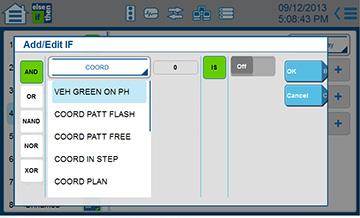
206 206 Cobalt Programming Manual

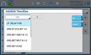
207 Cobalt Programming Manual 207

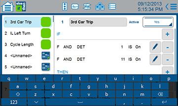
208 208 Cobalt Programming Manual
Cobalt Programming Manual
 Cobalt Programming Manual P/N 140-0903-001 Rev. 00 November 2013 Software Version: Cobalt - 32.58.00 Copyright 2013 by Econolite Group, Inc. ALL RIGHTS RESERVED Econolite Group, Inc. 3360 E. La Palma Avenue,
MonitorKey Operation Manual: content/uploads/ MonitorKey Operation Manual.pdf
 Additional Resources: MonitorKey Operation Manual: www.editraffic.com/wp content/uploads/888 1212 001 MonitorKey Operation Manual.pdf CMUip 2212 Operation Manual: www.editraffic.com/wp content/uploads/888
Wireless Studio. User s Guide Version 5.1x Before using this software, please read this manual thoroughly and retain it for future reference.
 4-743-161-12 (1) Wireless Studio User s Guide Version 5.1x Before using this software, please read this manual thoroughly and retain it for future reference. DWR-R01D/R02D/R02DN/R03D 2018 Sony Corporation
Modbus for SKF IMx and Analyst
 User manual Modbus for SKF IMx and SKF @ptitude Analyst Part No. 32342700-EN Revision A WARNING! - Read this manual before using this product. Failure to follow the instructions and safety precautions
Reno A&E Telephone: (775) Aircenter Circle Facsimile: (775)
 Aircenter Circle Facsimile: (775)") Reno A&E Telephone: (775) 826-2020 4655 Aircenter Circle Facsimile: (775) 826-9191 Reno, Nevada 89502 Internet: www.renoae.com USA e-mail: contact@renoae.com MODEL MMU2-1600G SERIES OPERATION MANUAL Firmware
Reno A&E Telephone: (775) 826-2020 4655 Aircenter Circle Facsimile: (775) 826-9191 Reno, Nevada 89502 Internet: www.renoae.com USA e-mail: contact@renoae.com MODEL MMU2-1600G SERIES OPERATION MANUAL Firmware
SQTR-2M ADS-B Squitter Generator
 SQTR-2M ADS-B Squitter Generator Operators Manual REVISION A B C D E F G H J K L M N P R S T U V W X Y Z December 2011 KLJ Instruments 15385 S. 169 Highway Olathe, KS 66062 www.kljinstruments.com NOTICE:
EdgeConnect Module Quick Start Guide ITERIS INNOVATION FOR BETTER MOBILITY
 EdgeConnect Module Quick Start Guide ITERIS INNOVATION FOR BETTER MOBILITY 493456301 Rev B April 2009 Table of Contents Installation... 1 Setup... 2 Operation... 4 Live Video... 4 Video Settings... 5 Network
Back Beat Bass. from Jazz to Rockabilly
 Back Beat Bass from Jazz to Rockabilly 2013 Hans Adamson, p 2013 Hans Adamson. All rights reserved. Art Vista is a trademark of Art Vista Productions. No part of the Licensed Material (as this term is
210E - 210ECL ECL ECL
 210E - 210ECL - 2010ECL - 2018ECL RMS Signal Monitor Operations Manual THIS MANUAL CONTAINS TECHNICAL INFORMATION FOR THE FOLLOWING SERIES OF MODEL 210/2010/2018 SIGNAL MONITORS, PCB Issue G: 210E, 210ECL,
RDS: The RDS, or Radio Data System, is supported in the g! interface where available.
 Manufacturer: Integra Integration Note Model Number(s): Integra 20.3/30.3/40.3/50.3/70.3/80.3 Core Module Version: 5.4 Comments: FW 1.09 (1091-0999-0210-9105) Document Revision Date: 1/15/2013 OVERVIEW
Agilent Technologies. N5106A PXB MIMO Receiver Tester. Error Messages. Agilent Technologies
 Agilent Technologies N5106A PXB MIMO Receiver Tester Messages Agilent Technologies Notices Agilent Technologies, Inc. 2008 2009 No part of this manual may be reproduced in any form or by any means (including
Integration Note. Any feature not specifically noted as supported should be assumed to be unsupported.
 Integration Note Manufacturer: Model Number(s): Crestron Processor Version: Driver Developer: Sky (UK) Sky+, Sky+ HD, Sky Multi-room Tested on 3 Series Processors, support for other versions not guaranteed
TF5 / TF3 / TF1 DIGITAL MIXING CONSOLE. TF StageMix User's Guide
 TF5 / TF3 / TF1 DIGITAL MIXING CONSOLE EN Note The software and this document are the exclusive copyrights of Yamaha Corporation. Copying or modifying the software or reproduction of this document, by
Getting Started Guide for the V Series
 product pic here Getting Started Guide for the V Series Version 9.0.6 March 2010 Edition 3725-24476-003/A Trademark Information POLYCOM, the Polycom Triangles logo and the names and marks associated with
VF-STB IP Appliance User Guide
 VF-STB IP Appliance User Guide Copyright 2007 Video Furnace, Inc. All Rights Reserved. Copyright 2002-2007 Video Furnace, Inc. All Rights Reserved This document refers to the current published version
Installation / Set-up of Autoread Camera System to DS1000/DS1200 Inserters
 Installation / Set-up of Autoread Camera System to DS1000/DS1200 Inserters Written By: Colin Langridge Issue: Draft Date: 03 rd July 2008 1 Date: 29 th July 2008 2 Date: 20 th August 2008 3 Date: 02 nd
Video Extender DS128 DSRXL. Instruction Manual. 8-Port Cat5 VGA Digital Signage Broadcaster with RS232 and Audio
 DS128 DSRXL Instruction Manual Video Extender 8-Port Cat5 VGA Digital Signage Broadcaster with RS232 and Audio Cat5 VGA Digital Signage Receiver with RS232 and Audio FCC Compliance Statement This equipment
FOTS100 User Manual. BIOPAC Systems, Inc. Opsens Inc. 42 Aero Camino, Goleta, CA Tel (805) , Fax (805)
 , Fax (805)") FOTS100 User Manual BIOPAC Systems, Inc. 42 Aero Camino, Goleta, CA 93117 Tel (805) 685-0066, Fax (805) 685-0067 WWW.BIOPAC.COM 1 WARRANTY All products manufactured by Opsens inc. are warranted to be free
FOTS100 User Manual BIOPAC Systems, Inc. 42 Aero Camino, Goleta, CA 93117 Tel (805) 685-0066, Fax (805) 685-0067 WWW.BIOPAC.COM 1 WARRANTY All products manufactured by Opsens inc. are warranted to be free
Getting Started Guide for the V Series
 product pic here Getting Started Guide for the V Series Version 8.7 July 2007 Edition 3725-24476-002/A Trademark Information Polycom and the Polycom logo design are registered trademarks of Polycom, Inc.,
V pro8 QUICK START GUIDE
 QUICK START GUIDE Welcome to your V pro8 FIRST STEPS POWERING ON CONNECTING YOUR COMPUTER Thank you for buying the Lawo V pro8, a true high-quality product developed and manufactured in Rastatt, Germany.
SPG700 Multiformat Reference Sync Generator Release Notes
 xx ZZZ SPG700 Multiformat Reference Sync Generator Release Notes This document supports firmware version 3.0. www.tek.com *P077123104* 077-1231-04 Copyright Tektronix. All rights reserved. Licensed software
CI-218 / CI-303 / CI430
 CI-218 / CI-303 / CI430 Network Camera User Manual English AREC Inc. All Rights Reserved 2017. l www.arec.com All information contained in this document is Proprietary Table of Contents 1. Overview 1.1
VIDEO ALARM VERIFICATION UNIT VIVER
 VIDEO ALARM VERIFICATION UNIT VIVER viver_en 09/08 The VIVER module provides remote video alarm verification, based on image sequences transmitted from cameras installed in the protected facility. The
Crestron TPMC-4SM Fusion RV Interface Operations Guide
 Crestron TPMC-4SM Fusion RV Interface Operations Guide The specific patents that cover Crestron products are listed at patents.crestron.com. Crestron, the Crestron logo and Fusion RV are either trademarks
EAN-Performance and Latency
 EAN-Performance and Latency PN: EAN-Performance-and-Latency 6/4/2018 SightLine Applications, Inc. Contact: Web: sightlineapplications.com Sales: sales@sightlineapplications.com Support: support@sightlineapplications.com
IP LIVE PRODUCTION UNIT NXL-IP55
 IP LIVE PRODUCTION UNIT NXL-IP55 OPERATION MANUAL 1st Edition (Revised 2) [English] Table of Contents Overview...3 Features... 3 Transmittable Signals... 3 Supported Networks... 3 System Configuration
EEG A1452 SCTE-104 Inserter Frame Card
 EEG A1452 SCTE-104 Inserter Frame Card Product Manual EEG Enterprises, Inc. 586 Main Street Farmingdale, New York 11735 TEL: (516) 293-7472 FAX: (516) 293-7417 Copyright EEG Enterprises, Inc. 2017 All
THD601DC Set-top box
 THD601DC Set-top box Contents 1. Safety... 1 2. Appearance... 2 3. Rear Panel Connection... 3 4. Remote... 4 5 First Time Set-Up... 7 6. Network Settings... 8 6.1 Available Networks and Checking Current
MaxView Cinema Kit Quick Install Guide
 SYSTEM SETUP The MaxView will work at any of the following display settings: INSTALLATION MaxView Cinema Kit Quick Install Guide Step 1 - Turn off your computer. Disconnect your monitor s VGA cable from
B. The specified product shall be manufactured by a firm whose quality system is in compliance with the I.S./ISO 9001/EN 29001, QUALITY SYSTEM.
 VideoJet 8000 8-Channel, MPEG-2 Encoder ARCHITECTURAL AND ENGINEERING SPECIFICATION Section 282313 Closed Circuit Video Surveillance Systems PART 2 PRODUCTS 2.01 MANUFACTURER A. Bosch Security Systems
Positive Attendance. Overview What is Positive Attendance? Who may use Positive Attendance? How does the Positive Attendance option work?
 Positive Attendance Overview What is Positive Attendance? Who may use Positive Attendance? How does the Positive Attendance option work? Setup Security Codes Absence Types Absence Reasons Attendance Periods/Bell
Celect Communications. Complete TV Users Guide
 Celect Communications Complete TV Users Guide 1 Contents Setting up your Remote... 4 Remote Guide... 5 Using the Guide Button... 8 Searching...10 Reminders...12 DVR Guide...13 Important Note...26 TV Main
C Module Description
 IQMMX -Input Router & ASI Distribution Amplifier C Module Description The IQMMX is an ASI to 1 switch, distribution amplifier and transport stream switcher with up to 8 outputs in double width form or
Kramer Electronics, Ltd. USER MANUAL. Model: VS x 1 Sequential Video Audio Switcher
 Kramer Electronics, Ltd. USER MANUAL Model: VS-120 20 x 1 Sequential Video Audio Switcher Contents Contents 1 Introduction 1 2 Getting Started 1 2.1 Quick Start 2 3 Overview 3 4 Installing the VS-120 in
1 OVERVIEW 2 WHAT IS THE CORRECT TIME ANYWAY? Application Note 3 Transmitting Time of Day using XDS Packets 2.1 UTC AND TIMEZONES
 1 OVERVIEW This application note describes how to properly encode Time of Day information using EIA-608-B Extended Data Services (XDS) packets. In the United States, the Public Broadcasting System (PBS)
Complete TV Users Guide
 Celect Communications Complete TV Users Guide Connected Your pathway to the world 1 2 Contents Setting up your Remote... 4 Remote Guide... 5 Using the Guide Button... 8 Searching...10 Reminders...12 DVR
TABLE OF CONTENTS 1. OVERVIEW INSTALLATION DA-3G CONNECTIONS SPECIFICATIONS SERIAL VIDEO INPUT...
 TABLE OF CONTENTS 1. OVERVIEW... 1 2. INSTALLATION... 3 2.1. 500DA-3G CONNECTIONS... 3 3. SPECIFICATIONS... 4 3.1. SERIAL VIDEO INPUT... 4 3.2. SERIAL VIDEO OUTPUT... 4 3.3. ELECTRICAL... 4 3.4. PHYSICAL...
OPERATORS & INSTALLATION MANUAL JOTRON AIS VIEWER WINDOWS PC SOFTWARE
 OPERATORS & INSTALLATION MANUAL JOTRON AIS VIEWER WINDOWS PC SOFTWARE AMENDMENT RECORD AMENDMENT NO. INCORP. BY DATE PAGE(S) VERSION CHANGE NOTE ( EM) 1 ES 06.10.2004 29 A 2 ES 04.03.2005 29 B Included
February 2007 Edition /A. Getting Started Guide for the VSX Series Version 8.5.3
 February 2007 Edition 3725-21286-009/A Getting Started Guide for the VSX Series Version 8.5.3 GETTING STARTED GUIDE FOR THE VSX SERIES Trademark Information Polycom, the Polycom logo design, and ViewStation
May 2006 Edition /A. Getting Started Guide for the VSX Series Version 8.5
 May 2006 Edition 3725-21286-008/A Getting Started Guide for the VSX Series Version 8.5 GETTING STARTED GUIDE FOR THE VSX SERIES Trademark Information Polycom, the Polycom logo design, and ViewStation are
E-MANUAL. Thank you for purchasing this Samsung product. To receive more complete service, please register your product at.
 E-MANUAL Thank you for purchasing this Samsung product. To receive more complete service, please register your product at www.samsung.com/register Model Serial No. Contents Connecting Antenna and External
IoT Toolbox Mobile Application User Manual
 Rev. 0 19 December 2017 User Manual Document information Info Keywords Abstract Content User Manual, IoT, Toolbox The IoT Toolbox is a mobile application developed by NXP Semiconductors and designed for
Getting started with
 Getting started with Electricity consumption monitoring single phase for homes and some smaller light commercial premises OVERVIEW: The OWL Intuition-e electricity monitoring system comprises of three
SECTION 686 VIDEO DECODER DESCRIPTION
 686 SECTION 686 VIDEO DECODER DESCRIPTION 686.01.01 GENERAL A. This specification describes the functional, performance, environmental, submittal, documentation, and warranty requirements, as well as the
User Guide. MonitorMix User Guide 1
 User Guide EN MonitorMix User Guide 1 Introduction Thank you for downloading MonitorMix app for ios or Android. With MonitorMix, you can control MIX/MATRIX/AUX mixes wirelessly for your CL, QL or TF series
R5 RIC Quickstart R5 RIC. R5 RIC Quickstart. Saab TransponderTech AB. Appendices. Project designation. Document title. Page 1 (25)
") Appendices 1 (25) Project designation R5 RIC Document title CONTENTS 2 (25) 1 References... 4 2 Dimensions... 5 3 Connectors... 6 3.1 Power input... 6 3.2 Video I... 6 3.3 Video Q... 6 3.4 Sync... 6 3.5
Appendices 1 (25) Project designation R5 RIC Document title CONTENTS 2 (25) 1 References... 4 2 Dimensions... 5 3 Connectors... 6 3.1 Power input... 6 3.2 Video I... 6 3.3 Video Q... 6 3.4 Sync... 6 3.5
Cablecast Server. Setup Guide. c Tightrope Media Systems For Cablecast version Build 74
 Cablecast Server Setup Guide c Tightrope Media Systems For Cablecast version 6.1.2 Build 74 Printed July 22, 2016 1 Cablecast Server Setup 1.1 Prerequisites 1.2 Overview of Setup Thank you for purchasing
CMU-212. ITS Cabinet Monitor Unit Operations Manual
 CMU-212 ITS Cabinet Monitor Unit THIS MANUAL CONTAINS TECHNICAL INFORMATION FOR THE CMU-212 AND CMUip-212 SERIES ITS CABINET MONITOR UNIT. Firmware Version 2.4 (vxx24) REVISION: OCTOBER 2017 pn 888-0212-001
Ambient Weather WS-01 Intelligent Color Changing Temperature Night Light with Ambient Backlight User Manual
 Ambient Weather WS-01 Intelligent Color Changing Temperature Night Light with Ambient Backlight User Manual Table of Contents 1 Introduction... 1 2 Warnings... 2 3 Getting Started... 2 3.1 Parts List...
User Instruction Manual IQSDA30/IQSDA32. Intelligent Reclocking High Performance HD-SDI/SD-SDI Distribution Amplifiers. snellgroup.
 User Instruction Manual IQSDA30/IQSDA32 Intelligent Reclocking High Performance HD-SDI/SD-SDI Distribution Amplifiers snellgroup.com IQSDA30/IQSDA32 www.snellgroup.com Information and Notices Information
ARRIS Solutions Inc. TERMS OF USE ARRIS SOFTWARE APPLICATIONS
 ARRIS Solutions Inc. TERMS OF USE ARRIS SOFTWARE APPLICATIONS (Effective as of February 10, 2015) PLEASE READ CAREFULLY This ARRIS Solutions, Inc. Terms of Use Agreement (this "Agreement") is a legal agreement
Softswitch128TM. SwitchingSystem. Setup and Maintenance Guide
 Softswitch128TM SwitchingSystem TM R Setup and Maintenance Guide Believeitornot,thisissupposed to look likeadictionary! Thisiconwascreated by BrentM.Nye,July 6,1995. Believeitornot,thisissupposed to look
DA CHANNEL AES AUDIO MIXER/ ROUTER MODULE
 DA5320 8-CHANNEL AUDIO MIXER/ ROUTER MODULE Document No. 14811 January 2005 14811 January 2005 Front Matter Page ii 14811 January 2005 Front Matter SIGMA ELECTRONICS's products are certified to comply
Copyright and Disclaimer
 Copyright and Disclaimer All rights reserved. No part of this publication may be reproduced, stored in a retrieval system, or transmitted in any form or by any means electronic, mechanical, photocopying,
FN:4181NX_M1.DOC MC4181NX MASTER CLOCK MC4181NX
 FN:4181NX_M1.DOC MC4181NX MASTER CLOCK MC4181NX TABLE OF CONTENTS 1.0 INTRODUCTION 2.0 SPECIFICATIONS 3.0 INSTALLATION 4.0 GETTING STARTED 4.1 The Auto-Prompt Display 4.2 The Cursor, Entering Data 4.3
Preset 10 Ethernet Interface Configuration & Owner s Manual
 Preset 10 Ethernet Interface Configuration & Owner s Manual model: PRE10E-A Doug Fleenor Design, Inc. 396 Corbett Canyon Road Arroyo Grande, CA 93420 (805) 481-9599 Voice and FAX Manual Revision 0 September
December 2006 Edition /A. Getting Started Guide for the VSX Series Version 8.6 for SCCP
 December 2006 Edition 3725-24333-001/A Getting Started Guide for the VSX Series Version 8.6 for SCCP GETTING STARTED GUIDE FOR THE VSX SERIES Trademark Information Polycom and the Polycom logo design are
X-Sign 2.0 User Manual
 X-Sign 2.0 User Manual Copyright Copyright 2018 by BenQ Corporation. All rights reserved. No part of this publication may be reproduced, transmitted, transcribed, stored in a retrieval system or translated
PACSystems* RX3i. Isolated Thermocouple Input Module, 6 Channels, IC695ALG306-EB Isolated Thermocouple Input Module, 12 Channels, IC695ALG312-EB
 September 2013 PACSystems* RX3i Isolated Thermocouple Input Module, 6 Channels, IC695ALG306-EB Isolated Thermocouple Input Module, 12 Channels, IC695ALG312-EB Isolated +24 VDC Power Isolated Thermocouple
Digital Video User s Guide THE FUTURE NOW SHOWING
 Digital Video User s Guide THE FUTURE NOW SHOWING Welcome The NEW WAY to WATCH Digital TV is different than anything you have seen before. It isn t cable it s better! Digital TV offers great channels,
Premium INSTALLATION AND USER GUIDE ENGLISH TAHOMA BOX. - INSTALLATION AND USER GUIDE. Rev A _01-16
 Premium INSTALLATION AND USER GUIDE ENGLISH - INSTALLATION AND USER GUIDE TAHOMA BOX Rev A _01-16 www.somfy.com TaHoma, connected homes the Somfy way! Remotely control and manage the devices in your home
User Manual CC DC 24 V 5A. Universal Control Unit UC-1-E. General Information SET. Universal Control Unit UC-1 Of Central Lubrication PAUSE CONTACT
 Universal Control Unit UC-1-E User Manual General Information Universal Control Unit UC-1 Of Central Lubrication CC DC 24 V 5A / M 15 SL /MK 31 M Z 30 General Information Contents Universal Control Unit
NI-DAQmx PlugIn September 2013
 NI-DAQmx PlugIn September 2013 Table of contents Table of contents Table of contents... 2 1 Important and general information... 4 1.1 Important information... 4 1.1.1 Safety and Warning instructions...
VIDEO GRABBER. DisplayPort. User Manual
 VIDEO GRABBER DisplayPort User Manual Version Date Description Author 1.0 2016.03.02 New document MM 1.1 2016.11.02 Revised to match 1.5 device firmware version MM 1.2 2019.11.28 Drawings changes MM 2
Design and Use of a DTV Monitoring System consisting of DVQ(M), DVMD/DVRM and DVRG
, DVMD/DVRM and DVRG") Design and Use of a DTV Monitoring System consisting of DVQ(M), DVMD/DVRM and DVRG When monitoring transmission systems it is often necessary to control the monitoring equipment and to check the measurement
Design and Use of a DTV Monitoring System consisting of DVQ(M), DVMD/DVRM and DVRG When monitoring transmission systems it is often necessary to control the monitoring equipment and to check the measurement
ExtIO Plugin User Guide
 Overview The SDRplay Radio combines together the Mirics flexible tuner front-end and USB Bridge to produce a SDR platform capable of being used for a wide range of worldwide radio and TV standards. This
Network Camera Operating Manual
 Network Camera Operating Manual Model No. WV-NW484S Before attempting to connect or operate this product, please read these instructions carefully and save this manual for future use. Preface About these
Model CMX3838A2 AV Matrix Switch with DSP audio (firmware 1.0)
") Model CMX3838A2 AV Matrix Switch with DSP audio (firmware 1.0) Overview: This product is a full featured video & audio matrix switch. It is most commonly used to independently distribute video & audio
Model CMX3838A2 AV Matrix Switch with DSP audio (firmware 1.0) Overview: This product is a full featured video & audio matrix switch. It is most commonly used to independently distribute video & audio
OPERATION MANUAL. FA-9600 LUT-Converter. Version Higher
 OPERATION MANUAL FA-9600 LUT-Converter Version 1.0.0 - Higher Software License Agreement This Software License Agreement is a legally binding agreement between you ( User ) and FOR-A Company Limited (
Master Time Clock MTC Users Manual
 Master Time Clock MTC-6000 Users Manual Midwest Time Control Phone (972)987-4408 Toll Free (888)713-0373 FAX (877)720-9291 www.midwest-time.com sales@midwest-time.com TABLE OF CONTENTS TOPIC PAGE GENERAL
Tebis application software
 Tebis application software Input products / ON / OFF output / RF dimmer Electrical / Mechanical characteristics: see product user manual Product reference Product designation TP device RF device WYC42xQ
Dimming actuators GDA-4K KNX GDA-8K KNX
 Dimming actuators GDA-4K KNX GDA-8K KNX GDA-4K KNX 108394 GDA-8K KNX 108395 Updated: May-17 (Subject to changes) Page 1 of 67 Contents 1 FUNCTIONAL CHARACTERISTICS... 4 1.1 OPERATION... 5 2 TECHNICAL DATA...
Six-Channel TDM Multiplexers for 3G, HD, SDI, and ASI. Installation and Operations. Manual
 Manual DigiLink DLC156 Function modules Six-Channel TDM Multiplexers for 3G, HD, SDI, and ASI Installation and Operations Manual WWW.ARTEL.COM ii DLC156 Function Modules Installation and Operations Manual
Installation and User Guide 458/CTR8 8-Channel Ballast Controller Module
 Installation and User Guide 458/CTR8 8-Channel Ballast Controller Module Helvar Data is subject to change without notice. www.helvar.com i Contents Section Page Introduction 1 Installation 2 1. Attach
TSW-560/TSW-760/TSW ", 7", and 10.1" Touch Screens. Supplemental Guide Crestron Electronics, Inc.
 TSW-560/TSW-760/TSW-1060 5", 7", and 10.1" Touch Screens Supplemental Guide Crestron Electronics, Inc. Crestron product development software is licensed to Crestron dealers and Crestron Service Providers
SignalTap Plus System Analyzer
 SignalTap Plus System Analyzer June 2000, ver. 1 Data Sheet Features Simultaneous internal programmable logic device (PLD) and external (board-level) logic analysis 32-channel external logic analyzer 166
AEROTRAK PORTABLE AIRBORNE PARTICLE COUNTER MODEL 9110 QUICK START GUIDE
 AEROTRAK PORTABLE AIRBORNE PARTICLE COUNTER MODEL 9110 QUICK START GUIDE Thank you for purchasing a TSI AeroTrak Model 9110 Portable Airborne Particle Counter (particle counter). This guide will help you
DX-10 tm Digital Interface User s Guide
 DX-10 tm Digital Interface User s Guide GPIO Communications Revision B Copyright Component Engineering, All Rights Reserved Table of Contents Foreword... 2 Introduction... 3 What s in the Box... 3 What
VSX Series Getting Started Guide
 VSX Series Getting Started Guide September, 2003 Edition 3725-21286-002/A VSX SERIES GETTING STARTED GUIDE Trademark Information Patent Information Polycom and the Polycom logo design are registered trademarks
DXI SAC Software: Configuring a CCTV Switcher. Table of Contents
 APPLICATION NOTE MicroComm DXI DXI SAC Software: Configuring a CCTV Switcher Table of Contents 1. Intent & Scope... 2 2. Introduction... 2 3. Options and Parameters... 2 3.1 When to switch the CCTV...2
Noise Detector ND-1 Operating Manual
 Noise Detector ND-1 Operating Manual SPECTRADYNAMICS, INC 1849 Cherry St. Unit 2 Louisville, CO 80027 Phone: (303) 665-1852 Fax: (303) 604-6088 Table of Contents ND-1 Description...... 3 Safety and Preparation
RADview-PC/TDM. Network Management System for TDM Applications Megaplex RAD Data Communications Publication No.
 RADview-PC/TDM Network Management System for TDM Applications Megaplex-2200 1994 2001 RAD Data Communications Publication No. 351-241-12/01 Contents Megaplex-2200 Edit Configuration Operations 1. Connecting
RD RACK MOUNT DIMMER OWNERS MANUAL VERSION /09/2011
 RD - 122 RACK MOUNT DIMMER OWNERS MANUAL VERSION 1.3 03/09/2011 Page 2 of 14 TABLE OF CONTENTS UNIT DESCRIPTION AND FUNCTIONS 3 POWER REQUIREMENTS 3 INSTALLATION 3 PLACEMENT 3 POWER CONNECTIONS 3 OUTPUT
User s Guide. Dimensions 4000 Series Control System. Topics at a Glance
 User s Guide Dimensions 4000 Series Control System Topics at a Glance Installation...See Installation Guide Quick Start Configuration...11 User Interface...8 Initial Setup...19 Scheduling...63 Scene Recording...54
Warranty and Registration. Warranty: One Year. Registration: Please register your product at Port, or. or Windows.
 7 7 Port, or or Windows Port Warranty and Registration Warranty: One Year Registration: Please register your product at www.aitech.com 2007 AITech International. All rights reserved. WEB CABLE PLUS PC-TO-TV
Cablecast SX. Setup Guide. c Tightrope Media Systems For Cablecast version Build 206
 Cablecast SX Setup Guide c Tightrope Media Systems For Cablecast version 5.2.11 Build 206 Printed June 5, 2015 1 Cablecast SX Setup 1.1 Prerequisites 1.2 Overview of Setup Thank you for purchasing a Cablecast
COPYRIGHT NOVEMBER-1998
 Application Notes: Interfacing AG-132 GPS with G-858 Magnetometer 25430-AM Rev.A Operation Manual COPYRIGHT NOVEMBER-1998 GEOMETRICS, INC. 2190 Fortune Drive, San Jose, Ca 95131 USA Phone: (408) 954-0522
SPG8000A Master Sync / Clock Reference Generator Release Notes
 xx ZZZ SPG8000A Master Sync / Clock Reference Generator Release Notes This document supports firmware version 2.5. www.tek.com *P077122204* 077-1222-04 Copyright Tektronix. All rights reserved. Licensed
Transmitter Interface Program
 Transmitter Interface Program Operational Manual Version 3.0.4 1 Overview The transmitter interface software allows you to adjust configuration settings of your Max solid state transmitters. The following
TECHNICAL MANUAL. Cheetah VIDEO MATRIX ROUTERS 3G VIDEO INPUT CARD WITH AUDIO DE-EMBEDDING AND 3G VIDEO OUTPUT CARD WITH AUDIO EMBEDDING
 TECHNICAL MANUAL Cheetah VIDEO MATRIX ROUTERS 3G VIDEO INPUT CARD WITH AUDIO DE-EMBEDDING AND 3G VIDEO OUTPUT CARD WITH AUDIO EMBEDDING Publication: 81-9059-0658-0, Rev. A August, 2009 Thank You!! for
imso-104 Manual Revised August 5, 2011
 imso-104 Manual Revised August 5, 2011 Section 1 Getting Started SAFETY 1.10 Quickstart Guide 1.20 SAFETY 1.30 Compatibility 1.31 Hardware 1.32 Software Section 2 How it works 2.10 Menus 2.20 Analog Channel
Crestron Room Scheduling Panels. User Guide Crestron Electronics, Inc.
 Crestron Room Scheduling Panels User Guide Crestron Electronics, Inc. Crestron product development software is licensed to Crestron dealers and Crestron Service Providers (CSPs) under a limited non-exclusive,
MICROSENS. Fast Ethernet Switch Modul 4x 10/100Base-TX, 1x 100Base-FX. Description. Features
 Fast Ethernet Switch Modul 4x 10/100Base-TX, 1x 100Base-FX Description This Ethernet Switch Module has been designed with 4x10/100Base-TX ports and 1x100Base-FX fiber optic port for the interconnection
2-/4-Channel Cam Viewer E- series for Automatic License Plate Recognition CV7-LP
 2-/4-Channel Cam Viewer E- series for Automatic License Plate Recognition Copyright 2-/4-Channel Cam Viewer E-series for Automatic License Plate Recognition Copyright 2018 by PLANET Technology Corp. All
The 6700 series Panel lock and destination protect
 Table of Contents 1 Introduction 4 2 Panel types 5 The 6700 series Panel lock and destination protect 3 Installation 10 Connector I/O Installing the power supply Earthing the panel Inserting and removing
SAT IF distribution system
 7. Technical specifications Type cs43 RF input frequency range pr. 50-350 MHz inputs number 4 level pr. 55...88 dbµv 60...93 dbµv symbol rate 3 45 Ms/s return loss/impedance > 0 db/75 Ω LNB powering/control
TABLE OF CONTENTS 1. OVERVIEW INSTALLATION VIDEO CONNECTIONS GENERAL PURPOSE INPUTS & OUTPUTS SPECIFICATIONS...
 TABLE OF CONTENTS 1. OVERVIEW...1 2. INSTALLATION...3 2.1. VIDEO CONNECTIONS... 3 2.2. GENERAL PURPOSE INPUTS & OUTPUTS... 4 3. SPECIFICATIONS...6 3.1. SERIAL DIGITAL VIDEO INPUTS... 6 3.2. SERIAL DIGITAL
FN:4181M5.DOC MC4181N SERIES MASTER CLOCKS MC4181N
 FN:4181M5.DOC MC4181N SERIES MASTER CLOCKS MC4181N TABLE OF CONTENTS 1.0 INTRODUCTION 2.0 SPECIFICATIONS 3.0 INSTALLATION 4.0 GETTING STARTED 4.1 The Auto-Prompt Display 4.2 The Cursor, Entering Data 4.3
what s in the Box? Camera transmitter with power cable 3M sticker 2 RVS SYSTEMS
 TM 1 what s in the Box? Camera transmitter with power cable 3M sticker 2 RVS SYSTEMS table of Contents introduction...4 features...5 Specifications...6-7 installation...8-9 Operations...10-15 Disclaimer...16
Wilkes Repair: wilkes.net River Street, Wilkesboro, NC COMMUNICATIONS
 1 Wilkes COMMUNICATIONS 336.973.3103 877.973.3104 Repair: 336.973.4000 Email: wilkesinfo@wilkes.net wilkes.net 1400 River Street, Wilkesboro, NC 28697 2 Table of Contents REMOTE CONTROL DIAGRAM 4 PLAYBACK