Reference Manual C DX 5624
|
|
|
- Martha Atkins
- 6 years ago
- Views:
Transcription
 FW V325 July 2008 Information in this document is subject to change without notice.")

1 Reference Manual C DX 5624 SD/HD Down Converter with Embedded Audio Support and Video and Audio D/A Conversion Revision 2.0 (HW Revision 03 required) FW V325 July 2008 Information in this document is subject to change without notice. No part of this document may be reproduced or transmitted in any form or by any means, electronic or mechanical for any purpose, without express written permission of LYNX Technik AG. LYNX Technik AG may have patents, patent applications, trademarks, copyrights or other intellectual property rights covering the subject matter in this document. Except as expressly written by LYNX Technik AG, the furnishing of this document does not give you any license to patents, trademarks, copyrights or other intellectual property of LYNX Technik AG or any of its affiliates. LYNX Technik AG Brunnenweg 3 D Weiterstadt Germany LYNX Technik AG all rights reserved
2 Contents WARRANTY... 3 REGULATORY INFORMATION... 4 EUROPE... 4 USA... 4 GETTING STARTED... 5 PACKAGING... 5 ESD WARNING... 5 PRODUCT DESCRIPTION... 6 INPUT FORMATS... 6 OUTPUT FORMATS... 6 CONVERSION MODES... 6 ASPECT RATIOS... 7 VIDEO PROCESSING... 8 AUDIO PROCESSING... 8 TEST PATTERNS... 9 FUNCTIONAL DIAGRAM... 9 MODULE LAYOUT CONNECTIONS VIDEO AUDIO INSTALLATION SETTINGS AND CONTROL MULTI FUNCTION SWITCH USING THE LOCAL DISPLAY MENUS MENU STRUCTURE LED STATUS INDICATORS CONTROL SYSTEM GUI MAIN TAB ANALOG VIDEO TAB ANALOG VIDEO GAIN TAB ANALOG AUDIO GAIN TAB SPECIFICATIONS SERVICE PARTS LIST TECHNICAL SUPPORT CONTACT INFORMATION Page 2 of 29
3 Warranty LYNX Technik AG warrants that the product will be free from defects in materials and workmanship for a period of two (2) year from the date of shipment. If this product proves defective during the warranty period, LYNX Technik AG at its option will either repair the defective product without charge for parts and labor, or will provide a replacement in exchange for the defective product. In order to obtain service under this warranty, customer must notify LYNX Technik of the defect before expiration of the warranty period and make suitable arrangements for the performance of service. Customer shall be responsible for packaging and shipping the defective product to the service center designated by LYNX Technik, with shipping charges prepaid. LYNX Technik shall pay for the return of the product to the customer if the shipment is within the country which the LYNX Technik service center is located. Customer shall be responsible for payment of all shipping charges, duties, taxes and any other charges for products returned to any other locations. This warranty shall not apply to any defect, failure, or damage caused by improper use or improper or inadequate maintenance and care. LYNX Technik shall not be obligated to furnish service under this warranty a) to repair damage resulting from attempts by personnel other than LYNX Technik representatives to install, repair or service the product; b) to repair damage resulting from improper use or connection to incompatible equipment; c) to repair any damage or malfunction caused by the use of non LYNX Technik supplies; or d) to service a product which has been modified or integrated with other products when the effect of such modification or integration increases the time or difficulty servicing the product. THIS WARRANTY IS GIVEN BY LYNX TECHNIK WITH RESPECT TO THIS PRODUCT IN LIEU OF ANY OTHER WARRANTIES, EXPRESS OR IMPLIED. LYNX TECHNIK AND ITS VENDORS DISCLAIM ANY IMPLIED WARRANTIES OF MERCHANTABILITY OR FITNESS FOR A PARTICULAR PURPOSE. LYNX TECHNIK`S RESPONISIBILITY TO REPAIR AND REPLACE DEFECTIVE PRODUCTS IS THE SOLE AND EXCLUSIVE REMEDY PROVIDED TO THE CUSTOMER FOR BREACH OF THIS WARRANTY. LYNX TECHNIK AND ITS VENDORS WILL NOT BE LIABLE FOR ANY INDIRECT, SPECIAL, INCIDENTIAL, OR CONSEQUENTIAL DAMAGES IRRESPECTIVE OF WHETHER LYNX TECHNIK OR THE VENDOR HAS ADVANCE NOTICE OF THE POSSIBILITY OF SUCH DAMAGES. Page 3 of 29
4 Regulatory information Europe Declaration of Conformity We LYNX Technik AG Brunnenweg 3 D Weiterstadt Germany Declare under our sole responsibility that the product TYPE: C DX 5624 To which this declaration relates is in conformity with the following standards (environments E1-E3): EN /1996 EN /1996 EN /2001 Following the provisions of 89/336/EEC and 73/23/EEC directives. Winfried Deckelmann Weiterstadt, November 2006 Place and date of issue Legal Signature USA FCC 47 Part 15 This device complies with part 15 of the FCC Rules. Operation is subject to the following two conditions: (1) This device may not cause harmful interference, and (2) this device must accept any interference received, including interference that may cause undesired operation. Note: This equipment has been tested and found to comply with the limits for a Class A digital device, pursuant to the part 15 of the FCC Rules. These limits are designed to provide reasonable protection against harmful interference when the equipment is operated in a commercial environment. This equipment generates, uses, and can radiate radio frequency energy and, if not installed and used in accordance with the instruction manual, may cause harmful interference to radio communications. Operation of this equipment in a residential area is likely to cause harmful interference in which case the user will be required to correct the interference at his own expense Page 4 of 29

5 Getting Started Most CardModules are installed into the rack frames and system tested in the factory. If this is an upgrade part or service exchange item then the module is supplied in a padded cardboard carton which includes the CardModule, rear connection plate and mounting screws. Packaging The shipping carton and packaging materials provide protection for the module during transit. Please retain the shipping cartons in case subsequent shipping of the product becomes necessary. Do not remove the module from its protective static bag unless observing adequate ESD precautions. Please see below. ESD Warning This product is static sensitive. Please use caution and use preventative measures to prevent static discharge or damage could result to module. Preventing ESD Damage Electrostatic discharge (ESD) damage occurs when electronic assemblies or the components are improperly handled and can result in complete or intermittent failure. Do not handle the module unless using an ESD-preventative wrist strap and ensure that it makes good skin contact. Connect the strap to any solid grounding source such as any exposed metal on the rack chassis or any other unpainted metal surface. Caution Periodically check the resistance value of the antistatic strap. The measurement should be between 1 and 10 Megohms. Page 5 of 29
6 Product Description The C DX 5624 is a high quality multi-format down converter providing down converted digital and analog video outputs + analog and digital audio outputs. Input Formats The module has one multi-format serial digital input with automatic input detection. The module will detect the following input standards and configure the input stage automatically for operation in the connected format. SDTV Formats HDTV Formats 525 / 59.94Hz 1080i / 59.94Hz 625 / 50Hz 1080i / 60Hz 1080i / 50Hz 720P / 59.94Hz 720P / 60Hz 720P / 50Hz Output Formats The module provides analog and digital video outputs. The analog video outputs are SDTV only and the available 3 BNC connections can be configured to provide the following analog video outputs. 3 x CVBS (composite) or 1 x YC (S-VHS) + 1 x CVBS (composite) or 1 x YUV or 1 x RGB (for HW Revision 03 only, older boards do not support this) Two serial digital outputs are also provided which can be configured to provide 2 x digital down converted outputs or 2 x re-clocked copies of the input signal (1>2 distribution amplifier) Conversion Modes HDTV Inputs > Down Conversion With a compatible HD source connected the module only supports down conversion between divisible frame rates. For example If a frame rate of 59.94Hz is connected to the input then the module can only output a down converted 59.94Hz output. This module will not function as standards converter. Please refer to the table below which shows compatible conversion modes Input Signal Converted Output Notes 1080i / 50Hz 625 / 50Hz 1080i / 59.94Hz 525 / 59.94Hz 1080i / 60Hz 525 / 59.94Hz 59.94Hz output will drop frame 720P / 50Hz 625 / 50Hz 720P / 59.94Hz 525 / 59.94Hz 720P / 60Hz 525 / 59.94Hz 59.94Hz output will drop frame Note. It is possible to convert between 60Hz and 59.94Hz. The resulting cumulative error will result in dropped frames on the converted outputs. Page 6 of 29
7 SDTV Inputs When a SDTV input is detected the module functions as a D/A converter + distribution amplifier providing analog and digital outputs of the connected SDTV input signal. Aspect Ratios The module supports three aspect ratio conversion modes which can be user selected using the local controls or preset with the optional control system. Letterbox This takes the 16:9 aspect ratio of the input HD signal and fits it into the 4:3 SD aspect ratio screen with black bars at the top and bottom of the image. Center Cut This mode cuts the center portion of the 16:9 input signal and fills the 4:3 SD aspect ratio screen. Stretch to Fill This mode takes the 16:9 input signal and distorts (vertically stretches) the image to fit the available 4:3 SD aspect ratio space. Page 7 of 29
8 Video Processing Note. All digital signal processing and D/A conversion is 10 bit. Video Proc Amp A basic video proc amp is provided for video adjustments. This provides for adjustable Y Gain / U Gain / V Gain / Black Level / Sharpness and Hue Note. Proc amp functions are preset to null. These parameters are adjustable via the local controls or central control system. Please refer to page 18 for illustrations of the available GUI controls Aperture Correction and Color Space Conversion Adjustable horizontal aperture correction is provided as well as selectable 709 > 601 color space (gamut) conversion. Color space conversion can be set to convert or transparent modes. In transparent mode the color space is passed from the input to the output. Note. Horizontal Aperture correction is factory preset for a flat frequency response on the SDTV outputs. (The down conversion filtering process results in a slight roll off in high frequencies). The amount of aperture correction applied is user adjustable via the local controls or via the central control system. Please refer to page 18 for illustrations of the available GUI controls. All module settings are automatically stored in internal flash ram and will survive power cycles and long term storage. Note. Settings will be written to flash RAM automatically after 10 seconds with no activity. This can be observed by the alarm LED flashing yellow three times. If power is removed before the settings have been stored the module will revert to the previous settings when powered up Audio Processing The module provides full audio support and will de-embed the complete audio payload (8xAES) from the incoming SDI signal. This audio is delayed to match the video processing delay (1 frame) and then re-embedded into the digital down converted outputs. Four of the de-embedded AES signals can be selected and output as external digital AES signals (balanced AES3 signals on the SubD connector). Two additional AES signals can be selected and output as balanced analog outputs via high quality 24 bit Audio D/A converters. Full scale ranging, adjustable gain and de-emphasis is provided for each analog audio output. Balanced analog audio outputs are provided on the integrated 25 pin SubD connector. DolbyE If the incoming SDI signal has an encoded DolbyE stream this will be de-embedded, delayed one frame and re-embedded into the same channels on the down converted SDI outputs. Providing the Dolby Guard Band was timed correctly on the input then the SDI outputs will have the correct DolbyE audio timing and guard band timing will be preserved. Page 8 of 29
.")
9 Test Patterns The module contains a selection of video test patterns which can be used for testing and fault finding. Patterns provided are 75% Colorbars, 75% Colorbars over Red, Full Field Black, Pathological PLL/EQ and Full field Blue (blue screen). Test patterns are provided on the analog and Digital video outputs in the selected format. If configured to pass the input HDTV to the digital outputs then both a Digital HD Test patterns and an Analog SDTV patterns are provided. By pre-selecting the input format (with no input connected) the Module can be used as a stand alone multi-format Test Pattern Generator. Functional Diagram Page 9 of 29


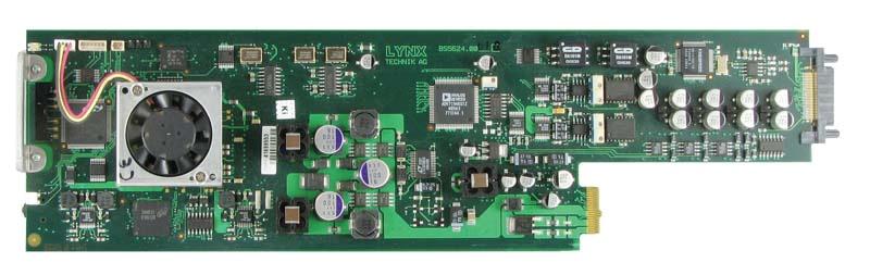
10 Module Layout Module Front Panel Module Rear Termination Panel Cooling Fan CardModule Layout Note. Cooling fan operation is monitored and alarmed when using the LYNX control system Page 10 of 29

11 Connections Video The C DX 5624 uses standard 75 Ohm BNC connectors. We recommend the use of high quality video cable for digital video connections to reduce the risk of errors due to excessive cable attenuation. Max cable lengths the module will support are shown below. SDTV = 250m Belden 8281 (270Mbits/s) HDTV = 140m Belden 1694A (1.4Gbits/s) Note. Due to the compact design of the connection plate it will be necessary to use a connection tool to secure the BNC video connectors. Audio Digital Audio (AES) The module provides for both Unbalanced (AES3id) and Balanced (AES3) connections. Unbalanced connections are made using the two BNC connectors (AES 1 and AES2) Balanced connections are made via the 25 pin SubD connector. Connection details shown below. Analog Audio Balanced analog audio connections are made using the 25 pin SubD connector. Connection details shown below. Pin Number Connection Pin Number Connection 1 Analog 1 L + 14 Analog 1 L - 2 Analog 1 L GND 15 Analog 1 R + 3 Analog 1 R - 16 Analog 1 R GND 4 Analog 2 L + 17 Analog 2 L - 5 Analog 2 L GND 18 Analog 2 R + 6 Analog 2 R - 19 Analog 2 R GND 7 AES AES 1-8 AES 1 GND 21 AES AES 2-22 AES 2 GND 10 AES AES 3-11 AES 3 GND 24 AES AES 4-25 AES 4 GND 13 (n.c) View looking INTO connector as seen on module Page 11 of 29
12 We recommend you use high quality screened (twisted pair) cable for the balanced audio connections. LYNX has an optional audio breakout cable which will bring out all audio connections to in line XLR connectors. Model number R AC M25-8 Audio Output Connections (un-balanced) Although the module is designed primarily for balanced line audio connections it is possible to make un-balanced audio connections to the module. NOTE. When used in this manor certain technical specifications of the module cannot be maintained. Wiring for balanced audio Screen Twisted pair blanced audio Balanced Pin Identification GND + Input / output - Input / output Wiring for un-balanced audio Signal Screen / GND Installation If this module was supplied as part of a system it is already installed in the rack enclosure. If the module was supplied as a field upgrade please follow the installation procedure below. NOTE Observe static precautions when handling card. Please see ESD warnings on Page 5. Each Card Module is supplied with a rear connection panel and two mounting screws. Please follow the following procedure for installation of the card module into the Series 5000 Card Frame. 1. Select a slot in the card frame where the CardModule will be located. 2. Remove the blank connection panel from the rear of the rack (if fitted) 3. Install the rear connection panel using the screws supplied. Do not tighten the screws fully 4. Slide the card module into the card frame and carefully check the CardModule connects to the rear connection plate. The card should fit easily and should not require excessive force to insert, if you feel any resistance, there could be something wrong with the rear connection panel location. Do not try and force the connection this may damage the connectors. Remove the rear connection panel and check alignment with the CardModule. 5. Insert and remove the CardModule a few times to ensure correct alignment and then tighten the two screws to secure the rear connection plate. Page 12 of 29
13 Settings and Control The C DX 5624 module has an integrated micro-controller, which enables the module to be configured and controlled locally using the multifunction switch and 4 character dot matrix display (or from remote using a GUI interface when using one of the optional controllers and control software). Once set, all settings are automatically saved in non-volatile internal memory. (Flash RAM) The module will always recall the last used settings. Multi-function Switch LED 1 (SDI Status) LED 1 (AES Status) CDX Matrix Display Side Front Multi Function Switch 5624 Switch Operations LED 3 (Alarm) Up Down Enter Multi Function Switch The CardModule is equipped with a multi-function switch located on the front bottom edge of the card. (See above) Using the Local Display Menus Making local adjustments to the module is done using the multifunction switch and the integrated 4-character dot matrix display. The menu system is layered, and navigation through the system is done using the UP and DOWN functions of the switch. ENTER is used to move between menu levels and also enter a selection. Switch Function UP DOWN ENTER Operation Move UP within a level Move down within a level Change levels / Make selection Page 13 of 29
14 Menu Structure The Menu structure is defined in the next table, and should be used when navigating through the system. ENTER moves between levels UP/DOWN moves between items within the level When you enter a new setting the system will jump one level in the menu system. The selection in the menu structure will take you one level when selected. When an item is selected which has several setting possibilities the first value displayed will be the value currently stored in the system. The order of the available settings for any menu item in the table supplied does not represent the order the settings will actually be displayed. If left unattended, the menu will default to the root display after a preset timeout. LEVEL 1 LEVEL 2 LEVEL 3 LEVEL 4 LEVEL 5 LEVEL 6 DESCRIPTION CDX 5624 OUT DVID DNCV CSCV APRT AVID SD S/HD LBOX FILL CCUT OFF ON LUMA off OFF ON FRMT Root Display Dig Output Video SDTV Input Loop Through Down Converter Mode Letterbox Stretch to fill Center Cut Color Space Conversion Transparent (bypass) 709>601 convert Convert only Chroma Aperture Correction No Aperture Correction Aperture Correction ON Set Level Analog Video Format CVBS 3 x Composite YUV 1 x YUV SVID 1 x YC + 1 x CVBS RGB 1 x RGB Page 14 of 29
15 PED FILT LIM LINE VBI LEVL Remove Pedestal OFF Pedestal removed ON Pedestal added Filter Selections LUM Luminance LP Low Pass NTCH Notch EXT Extended Filter CIF CIF Filter CHRO Chroma Filter MHz MHz MHz MHz MHz CIF CIF Filter QCIF QCIF filter Luma undershoot Limiter OFF Off IRE IRE IRE Active Line Duration CCIR CCIR 601 ITUB ITU-B 470 Vertical Blanking BLNK Blank Completely TRA Pass transparently Level Adjustments LUM Luminance CHRO Chrominance BLK Black Level Page 15 of 29
16 TEST AAUD AUTO SEL FSLV CH12CH34 OFF BLK PLL BAR BRED BLUE OFF BLK 12dB 15dB 18dB 20dB 22dB 24dB GAIN MUTE DEMP CH1 CH2 CH12 CH3 CH4 CH34 OFF ON OFF ON Analog Audio Full Scale Level 12dB Full Scale 15dB Full Scale 18dB Full Scale 20dB Full Scale 22dB Full Scale 24dB Full Scale Audio Channel Select Gain Adjustment (CH12 = Channels 1 and 2 Ganged together) (CH 34 = Channels 3 and 4 Ganged together) Mute Audio Audio De-emphasis Test Pattern Auto Test Pattern Auto mode OFF Full field Black Phase Lock Loop ColorBars Color bars / Red Blue Screen Test Pattern OFF Full field Black Page 16 of 29
17 RSET STD NO YES PLL Phase Lock Loop BAR ColorBars BRED Color bars / Red BLUE Blue Screen Test Pattern Standard (SDTV) (SDTV) 720p P 60Hz 720p P 50Hz 1080i i 60Hz 1080i i 50Hz Factory Reset No Yes LED Status Indicators The C DX 5624 module has LED indicators that serve as alarm and status indication for the module. Function is described below. SDI Status LED 1 LED Color Indication Green Input 1 SDI Present Red Input Missing AES Status LED 2 LED Color Indication Green AES 1 and AES 2 Present Yellow Only one AES Present Red No Audio Present Alarm LED 3 LED 1 (SDI Status) Multi Function Switch CDXDown Converter LED 1 (AES Status) 5624 Matrix Display LED Color Green Yellow Red Indication Video Present PLL Locked Test Pattern Selected No Video Present / PLL Unlocked LED 3 (Alarm) Page 17 of 29
 extended features is possible using this interface. Access to the GUI requires the use of the optional LYNX control system Note.")

18 Control System GUI All LYNX CardModules support a computer interface which allows setting the modules parameters using a simple GUI interface. Access to all standard features (and in some cases) extended features is possible using this interface. Access to the GUI requires the use of the optional LYNX control system Note. Any settings made using the control system overrides any local settings made on the module. All settings are stored in internal flash ram and will survive power cycles and long term storage. The GUI screenshots below show the settings and adjustments possible for the C DX 5624 CardModule. The above screenshot shows the complete module GUI. The Device info area contains information about the module including name and firmware revision. If used as part of a larger system (using the LYNX central control system) the modules position and physical location is displayed above the locate button. Note. The Locate function us a tool used to quickly identify a module in larger systems. Selecting locate will flash the module alarm LED yellow. (does not effect module operation) The first screen you see when the module is selected is the Main tab this is a graphical representation of the modules function and signal flow (left to right). Clicking on processing boxes where shown will link to other GUI screens with controls for these specific functions. Page 18 of 29
 There are a number of Tabs associated with each Module which splits up the modules")

19 The area at the bottom of the screen is the error log. Any fault condition will be timestamps and entered into the log (as long as the controller / adapter is connected) There are a number of Tabs associated with each Module which splits up the modules settings into a number of separate screens. The various GUI screens and functions are described below. Main Tab This screen is the main GUI interface and is presented first when the module is displayed in the GUI. The layout replicates function and the signal flow if from left to right. Selections are made using onscreen sliders, radio buttons, drop down selections and checkboxes. Input Detection On the left the SDI input is detected and the format displayed on screen (in green) Deembedder The first stage is the audio deembedder. The four audio groups are represented by the dark grey boxes and the individual audio signals within each AES channels are shown as being present when highlighted green. This is a good reference for checking embedded audio status on the incoming SD/HDTV SDI stream. All AES channels (8) are available on an audio crossbar which permits selection of AES channels for the digital and analog audio output stages. (Selected using the radio buttons). Each selected AES stream can be individually muted using the checkboxes provided. Although not graphically shown, all AES channels (8) are fed through a fixed 1 Frame delay and embedded into the down converted digital outputs. Page 19 of 29
20 Test Pattern This is where the internal test pattern can be switched on via the drop down selections. This will override any input signal and is present on all outputs (analog and digital). Selections provided are: OFF (default) Color bars Color Bars over Red Full field Black Pathological PLL/EQ Blue Screen Auto Test Pattern When the input signal is lost you can configure the module to automatically switch in a test pattern. Selections provided are. OFF (default) Color bars Color Bars over Red Full field Black Pathological PLL/EQ Blue Screen Test Pattern Standard Using this drop down selection it s possible to configure the standard of the internal test signal. This can be preset to follow the last input standard connected or forced into any independent standard which is useful if using the module as a test pattern source. Possible standard selections are: Follow Last Input (default) 525 / 59.94Hz 625 / 50 Hz 1080i / 59.94Hz 1080i / 60Hz 1080i / 50Hz 720P / 59.94Hz 720P / 60Hz 720P / 59.94Hz Down Converter Mode This drop down selection defines the aspect ratio reproduction for the converted outputs Selections are Center Cut 4:3 (default) Letterbox Stretch to Fill Color Space Conversion This drop down selection configures the color space converter. There are three possiblke settings Bypass (Passes the color space on the input) Convert (Performs a 709>601 color space conversion) Luma in bypass (Only converts the chrominance portion of the signal) Page 20 of 29
. The checkbox can be used to switch aperture ON and OFF. (ON= Default).")
21 Aperture Correction We provide a horizontal aperture corrector for the converted outputs which permits the sharpening or softening of the SDTV outputs (a slight roll off in high frequency is a normal part of the down conversion filtering process). The checkbox can be used to switch aperture ON and OFF. (ON= Default). When set to ON a small preset amount of correction is applied to produce a flat frequency response on the outputs. When set to OFF all Aperture correction is removed. The amount of aperture correction is adjustable (from the factory preset) range + 30 to -80. Adjustments in the positive direction will sharpen the image and the negative direction will soften the image. SDI output routing There are two small radio buttons which can be used to change the SDI digital outputs. One selection takes the signal before the down converter and will provide two re-clocked outputs of the incoming SDI signal. The other selection (default) provides two converted digital outputs. Output Standard The output standard is indicated in green for the analog and digital outputs. Note The down converter will automatically select the correct output standard depending on the connected input standard. For example if a 50Hz input signal is detected then a 625 PAL output will be provided. Likewise if a 59.94Hz or 60Hz input is detected then a NTSC 59.94Hz output will be provided. Analog Video Tab This GUI screen is where you would access all the controls for the analog to digital conversion and proc functions Page 21 of 29
22 Output Format Use this drop down selection to configure the analog outputs. Selections are 3 x CVBS 1 x CVBS + YC YUV RGB The Add Pedestal function is enabled when a NTSC is being provided and checking this box will add a 7.5IRE Pedestal to the analog outputs. NTSC Output Options There are two check boxes provided which are for configuration of the video signal when in NTSC (525) output mode. Add pedestal (when selected) will add a 7.5IRE pedestal to the analog outputs. PAL M will configure the NTSC outputs to the PAL M standard. PAL Output Options There is one selection possible when in PAL (625) mode. When selected this will format the outputs into the PAL N video standard. Luminance Output Filter This drop down selection allows the selection of the Luminance filtering characteristics for the analog to digital converter. Settings are listed below followed by the filter response characteristics. Extended Mode (Default) Extended Mode (default) Notch Filter Lowpass CIF Notch Filter (PAL) Low Pass (PAL) Page 22 of 29
23 CIF (PAL) C DX 5624 Reference Manual. Rev 2.0 Chrominance Filter It s also possible to configure the filter response for the chrominance portion of the signal. The drop down box provides the following selections and the filter characteristics are shown for each. 3.0 MHz (default) 0.65 MHz 1.0 MHz 1.3 MHz 2.0 MHz CIF QCIF 3.0 MHz (Default) 0.65 MHz 1.0 MHz Page 23 of 29
24 1.3 MHz 2.0 MHz CIF QCIF Output Options Blank VBI When selected this will completely blank any information in the vertical interval. Left unchecked the module will pass any VBI information transparently. (only valid for the bypass channel, processed outputs (down converted) will have the vertical interval blanked) Chrominance off When selected this will turn off the chrominance part of the signal and a luminance only (black and white) image will be provided. Burst off When in composite mode this will remove the burst portion of the composite signal from the composite outputs. Active Line Duration The active line length can be switched between analog and digital blanking. Selections provided are: ITU-B 470 (702 pixels active) = analog blanking CCIR 601 (720 pixels active) = digital blanking Page 24 of 29
 by the time period specified (default 0) Chrominance Delay This allows for the delay of the Chrominance")
25 Special Functions These functions are for specialized use only and should be left set to the factory defaults unless you are sure you need to adjust these parameters. Luminance Delay This allows for the delay of the Luminance signal relative to sync (and Chroma) by the time period specified (default 0) Chrominance Delay This allows for the delay of the Chrominance signal relative to sync (and Luma) by the time period specified (default 0) Double Buffering This is double buffers the video signal so that any changes made to the module settings over the remote Ic2 interface occurs in the vertical blanking interval. Analog Video Gain Tab This GUI screen provides access to the internal video processing amplifier where gain levels can be adjusted and set. Default is a null setting for all adjustments. Note. The buttons at the bottom of each slider will return the settings to the factory preset null setting. Options Y level The Y level can be changed, which depends on the application. Possible settings are: SMPTE (default) BETACAM UV Level The UV levels used can be preset which depends on the application. Possible settings are 700mv 1000mv 648mv Page 25 of 29
 -1.5 IRE -6.")
26 Luminance Undershoot Limiter With this selection is possible to limit the undershoot of the luminance portion of the signal. The following limits are possible selected by the drop down box: Disable (default) -1.5 IRE -6.0 IRE -11 IRE Video Adjustments A bank of six on screen sliders is provided for the adjustment of various video parameters. These settings apply only for the analog video outputs. Settings provided are: Luma Level U Level V Level Black Level Sharpness Hue To operate a slider it must be enabled by selecting the check box above, dragging the slider will change the desired level. To return a slider to the factory default (null) setting click the button below the slider. Note. Sharpness is a different adjustment to the Horizontal Aperture Correction provided earlier in the processing chain. Analog Audio Gain Tab Page 26 of 29
27 This GUI screen provides access to all the analog audio adjustments and settings. The gain adjustment provided is +/- 3dB from the selected Full Scale Level (FS Level) FS Level This sets the full scale level (scaling) of the analog audio signal. This can vary by region and installation. Please check with your studio engineer what FS level is defined as standard and make the appropriate selection. Default in 18dB (which is typical for European markets) Analog Out 1 and 2 Left and Right Adjustments Two identical adjustment panels are provided for the stereo analog audio outputs. Swap Left and Right When selected this will swap the left and right channels Deemphasis When selected this will apply deemphasis to the audio output. Mute When selected this will mute the analog audio outputs (silence) Gain Adjustments Adjustable gain is provided via two sliders, one for the right and one for the left channel. These can be moved on screen to the desired settings. The two sliders can be ganged together at any time by selecting the linking checkbox below the sliders. The return the sliders to 0 (null) press the button below the sliders. Note. The zero or null setting for the sliders will set the audio to the FS level defined. The adjustment provided is +/- 3dB from the selected FS level. Reset Factory Defaults If you are unsure of the settings or have managed to set the module into a strange mode of operation and wish to recover the factory defaults - this can be done by selecting Device > Reset Factory Defaults from the Device drop down menu at the top of the GUI. Page 27 of 29
28 Specifications Video Input Signal Type Serial Digital Video (SDI) SMPTE 292M, 344M, 259M with automatic input standard detection Supported Formats 525/59.94Hz 625/50Hz 1080i/59.94Hz/60Hz/50Hz 720P/59.94Hz/60Hz/50Hz Input Imedance 75 Ω Input Level 0.8v Connector BNC Return Loss >15dB (270Mbits) >10dB (1.485Gbits) Digital Video Ouputs Signal 2 x Serial Digital Video (SDI) SMPTE 292M, 344M, 259M Output Imedance 75 Ω Output Level 0.8v pp +/- 10% Return Loss > 15dB (1.5 Ghz) Connection BNC Jitter <0.20 UI (270 Mbits) <0.25 UI (1.485Gbits) Analog Video Outputs Modes 3 x CVBS or 1 x CVBS + YC or 1 x YUV Return Loss >35dB (5.75MHz) Signal to Noise > 60dB D/A Conversion 10 bits and 54 MHz (4x over sampling) Digital Audio Outputs Signal 4 x AES3 (balanced) Impedance 110 Ω Connectors 25 pin SubD Mode Select any 4 AES signals from de-embedded audio (8xAES) Analog Audio Outputs Signal 4 x Balanced analog audio (2 x Stereo L+R) Connector 25 pin SubD Dynamic Range >90dB Signal to Noise >85dB Conversion 24 bit Output level -39dB..+24dB in 0.5dB increments (default 18dB) Electrical Operating Voltage + 12 VDC Power Consumption 9 W Safety IEC 950 / EN / VDE 0805 Mechanical Size 283mm x 78mm Weight CardModule 150g, connector plate 70g Ambient Temperature 5ºC 40ºC Maintaining Specifications Humidity 90% non condensing Page 28 of 29


29 Service Parts List Due to the very dense design and high level of integration there the module is not user serviceable. Please contact LYNX for repairs or to request an exchange unit. There is one consumable part used on this module which is the cooling fan. A service kit is available to exchange the fan. Ordering information below. Part type: Cooling Fan Service Kit Series 5000 CardModules Technical Support If you are experiencing problems, or have questions please contact your local distributor for further assistance. Technical support is also available from our website. Please do not return products to LYNX without an RMA. Please contact your authorized dealer or reseller for more details. More detailed product information and product updates may be available on our web site: Contact Information Please contact your local distributor; this is your local and fastest method for obtaining support and sales information. LYNX Technik can be contacted directly using the information below. Address LYNX Technik AG Brunnenweg 3 D Weiterstadt Germany. Website info@lynx-technik.com LYNX Technik manufactures a complete range of high quality modular products for broadcast and Professional markets, please contact your local representative or visit our web site for more product information. Page 29 of 29
Reference Manual C DX 5025
 Reference Manual C DX 5025 SDI embedded to analog Audio & Video Converter Revision 1.1 FW V342 October 2009 Information in this document is subject to change without notice. No part of this document may
Reference Manual D VD 5820
 Reference Manual D VD 5820 3GBit/s Dual SDI/ASI Distribution Amplifier Revision 1.0 May 2010 This Manual Supports Device Revisions: D VD 5820 Firmware Revision 377 Control System GUI Release 4.7.3 Information
Reference Manual D VD 5602
 Reference Manual D VD 5602 Dual HD > SD Digital Down Converter Revision 2.0 November 2009 This Manual Supports Device Revisions: D VD 5602 Firmware Revision 334 Control System GUI Release 4.6.6 Information
CardModule. Reference Manual. Series C DA Channel SDI to CVBS Converter. Version 1.0
 Reference Manual C DA 5005 5 Channel SDI to CVBS Converter Version 1.0 Series 5000 CardModule LYNX Technik AG Brunnenweg 3 D-64331 Weiterstadt Germany www.lynx-technik.com Information in this document
Reference Manual C DX 3624
 Reference Manual C DX 3624 SD/HD Monitoring Down Converter with Embedded Audio Support and Video and Audio D/A Conversion Revision 1.2 December 2006 Information in this document is subject to change without
Reference Manual D VA 5718 L D VA 5724
 LYNXTechnik AG Broadcast Television Equipment Reference Manual D VA 5718 L 1>8 Analog Video Distribution Amplifier with passive loop out D VA 5724 Dual 1>4 Analog Video Distribution Amplifier Revision
CardModule. Reference Manual. Series P VD 5005 G Video Media Processor (Frame Synch with Audio Processing for embedded Audio) Version 1.
 Version 1.") Version 1.4 Reference Manual P VD 5005 G Video Media Processor (Frame Synch with Audio Processing for embedded Audio) Series 5000 CardModule LYNX Technik AG Brunnenweg 3 D-64331 Weiterstadt Germany www.lynx-technik.com
Version 1.4 Reference Manual P VD 5005 G Video Media Processor (Frame Synch with Audio Processing for embedded Audio) Series 5000 CardModule LYNX Technik AG Brunnenweg 3 D-64331 Weiterstadt Germany www.lynx-technik.com
P VD 5000 G Video Media Processor (Frame Synchronizer) P VD 5000 G. REF loop. REF in. SDI in 2. SDI in 1. SDI 2 loop. SDI 1 loop. SDI out 2.
 P VD 5000 G. REF loop. REF in. SDI in 2. SDI in 1. SDI 2 loop. SDI 1 loop. SDI out 2.") Version 1.0 Reference Manual P VD 5000 G Video Media Processor (Frame Synchronizer) P VD 5000 G Series 5000 CardModule LYNX Technik AG REF in SDI in 1 SDI 1 loop SDI out 1 Delay out REF loop SDI in 2 SDI
Version 1.0 Reference Manual P VD 5000 G Video Media Processor (Frame Synchronizer) P VD 5000 G Series 5000 CardModule LYNX Technik AG REF in SDI in 1 SDI 1 loop SDI out 1 Delay out REF loop SDI in 2 SDI
CardModule. Reference Manual. Series C AD 5122 CVBS to SDI Converter & Frame Synchronizer. Version 1.0
 Version 1.0 Reference Manual C AD 5122 CVBS to SDI Converter & Frame Synchronizer Series 5000 CardModule LYNX Technik AG Brunnenweg 3 D-64331 Weiterstadt Germany www.lynx-technik.com Information in this
MiniModules. Reference Manual. Series D VD 3620 Dual HD / SD Digital Video Distribution Amplifier
 Reference Manual D VD 3620 Dual HD / SD Digital Video Distribution Amplifier Series 3000 MiniModules LYNX Technik AG Brunnenweg 3 64331 Weiterstadt Germany www.lynx-technik.com Information in this document
MiniModules. Reference Manual. Series C DA 3000 SDI to Analog Video Converter
 Reference Manual C DA 3000 SDI to Analog Video Converter Series 3000 MiniModules LYNX Technik AG Brunnenweg 3 64331 Weiterstadt Germany www.lynx-technik.com Information in this document is subject to change
MiniModules. Reference Manual. Series C AD Bit CVBS / YC to SDI Converter. Ver 1.1 Ver
 Reference Manual C AD 3100 12 Bit CVBS / YC to SDI Converter Ver 1.1 Ver Series 3000 MiniModules LYNX Technik AG Brunnenweg 3 64331 Weiterstadt Germany www.lynx-technik.com Information in this document
yellobrik Reference Manual P MV G/HD/SD Quad Split Multiviewer Revision 1.1 March 2016 Broadcast Television Equipment
 yellobrik Reference Manual P MV 1841 3G/HD/SD Quad Split Multiviewer Revision 1.1 March 2016 LYNXTechnik AG Broadcast Television Equipment This Manual Supports Device Revisions: P MV 1841 Firmware Revision
MiniModules. Reference Manual. Series P MX 3312/3313 D Dual Analog Audio Multiplexer. LYNX Technik AG
 Reference Manual P MX 3312/3313 D Dual Analog Audio Multiplexer Series 3000 MiniModules LYNX Technik AG P MX 3312 D SDI IN n.c. SDI out 1 SDI out 2 SDI out 3 Audio in SDI out 4 Dual Analog Audio Multiplexer
MiniModules. Reference Manual. Series D VA 3120 Dual Analog Video Distribution Amplifier
 Reference Manual D VA 3120 Dual Analog Video Distribution Amplifier Series 3000 MiniModules LYNX Technik AG Brunnenweg 3 64331 Weiterstadt Germany www.lynx-technik.com Information in this document is subject
Broadcast Television Equipment. Reference Manual P DM 5380 P DM 5380 O. SD / HD / 3 GBit/s Multi-format analog Audio Embedder / Deembedder
 LYNXTechnik AG Broadcast Television Equipment Reference Manual P DM 5380 P DM 5380 O SD / HD / 3 GBit/s Multi-format analog Audio Embedder / Deembedder Revision: 1.1 August 2013 This Manual Supports Device
Reference Manual P DM 5288 B/D. SD / HD Multi-format AES Audio Embedder / Deembedder. Revision: 1.3 May 2010
 Reference Manual P DM 5288 B/D SD / HD Multi-format AES Audio Embedder / Deembedder Revision: 1.3 May 2010 This Manual Supports Device Revisions: P DM 5288 Firmware Revision 376 Control System GUI Release
Reference Manual P VD 5660 D P VD 5660 B
 Reference Manual P VD 5660 D P VD 5660 B Dual Channel SD/HD Multi-format Frame Synchronizer with Full Embedded and External AES Audio Support Revision 2.4 June 2010 This Manual Supports Device Revisions:
Reference Manual P VD 5660 D P VD 5660 B. Dual Channel SD/HD Multi-format Frame Synchronizer with Full Embedded and External AES Audio Support
 Reference Manual P VD 5660 D P VD 5660 B Dual Channel SD/HD Multi-format Frame Synchronizer with Full Embedded and External AES Audio Support Revision 2.7 February 2014 This Manual Supports Device Revisions:
D10C2 10-bit Serial Digital to Composite/ Component Converter User Manual
 D10C2 10-bit Serial Digital to Composite/ Component Converter User Manual October 25, 2003 P/N 101640-00 2 Trademarks AJA, Io, and Kona are trademarks of AJA Video, Inc. All other trademarks are the property
Broadcast Television Equipment. Reference Manual P DM 5240 D P DM 5240 U. SD/HD/3G Multi-format digital Audio Embedder / Deembedder
 LYNXTechnik AG Broadcast Television Equipment Reference Manual P DM 5240 D P DM 5240 U SD/HD/3G Multi-format digital Audio Embedder / Deembedder Revision 2.0 February 2015 This Manual Supports Device Revisions:
D5CE Serial Digital Encoder
 D5CE Serial Digital Encoder User Manual December 5, 2003 P/N 101635-00 2 Trademarks AJA, Io, and Kona are trademarks of AJA Video, Inc. All other trademarks are the property of their respective holders.
Broadcast Television Equipment. Reference Manual P DM 5290 D P DM 5290 U
 LYNXTechnik AG Broadcast Television Equipment Reference Manual P DM 5290 D P DM 5290 U SD / HD / 3 GBit/s Multi-format AES Audio & Data Embedder / Deembedder & Shuffler Revision: 1.1 August 2013 This Manual
Broadcast Television Equipment. Reference Manual P VD 5840 D P VD 5840 U P VD 5840 DO P VD 5840 UO
 LYNXTechnik AG Broadcast Television Equipment Reference Manual P VD 5840 D P VD 5840 U P VD 5840 DO P VD 5840 UO Dual Channel SD/HD/3G Multi-format Frame Synchronizer with Full Embedded and External AES
RD10MD Dual HD to SD Down Converter R-series Card Module
 RD0MD Dual HD to SD Down Converter R-series Card Module User Manual March 30, 2006 P/N 0665-00 2 Trademarks AJA, Io, and Kona are trademarks of AJA Video, Inc. All other trademarks are the property of
Broadcast Television Equipment. Reference Manual C MX 5710
 LYNXTechnik AG Broadcast Television Equipment Reference Manual C MX 5710 HD/SD Analog Video to SDI Converter with Frame Synchronizer, Analog Audio Inputs and AES Ports Revision 1.0 July 2015 This Manual
R20CE 10-bit Encoder. R-series Card Module User Manual. August 25, 2003 P/N
 R20CE 10-bit Encoder R-series Card Module User Manual August 25, 2003 P/N 101646-00 2 Trademarks AJA, Io, and Kona are trademarks of AJA Video, Inc. All other trademarks are the property of their respective
Reference Manual PTG 5610 B/D
 Reference Manual PTG 5610 B/D Multi-format SD/HDSDI Video and AES Audio Test Generator Revision 1.0 February 2008 This Manual Supports Device Revisions: PTG 5610B/D Firmware Revision 235.4.17 Control System
AES-402 Automatic Digital Audio Switcher/DA/Digital to Analog Converter
 Broadcast Devices, Inc. AES-402 Automatic Digital Audio Switcher/DA/Digital to Analog Converter Technical Reference Manual Broadcast Devices, Inc. Tel. (914) 737-5032 Fax. (914) 736-6916 World Wide Web:
3G/HD/SD-SDI to HDMI Converter
 3G/HD/SD-SDI to HDMI Converter Model #: 3G/HD/SD-SDI to HDMI Converter 2010 Avenview Inc. All rights reserved. The contents of this document are provided in connection with Avenview Inc. ( Avenview ) products.
AES-404 Digital Audio Switcher/DA/Digital to Analog Converter
 Broadcast Devices, Inc. AES-404 Digital Audio Switcher/DA/Digital to Analog Converter Technical Reference Manual Broadcast Devices, Inc. Tel. (914) 737-5032 Fax. (914) 736-6916 World Wide Web: www.broadcast-devices.com
AES Channel Digital/Analog Audio Switcher/DA/Digital to Analog Converter
 Broadcast Devices, Inc. AES-408 8 Channel Digital/Analog Audio Switcher/DA/Digital to Analog Converter Technical Reference Manual Broadcast Devices, Inc. Tel. (914) 737-5032 Fax. (914) 736-6916 World Wide
PRO-ScalerHD2V HDMI to VGA & Audio Scaler Converter. User s Guide. Made in Taiwan
 PRO-ScalerHD2V HDMI to VGA & Audio Scaler Converter User s Guide Made in Taiwan Congratulations for owning a gofanco product. Our products aim to meet all your connectivity needs wherever you go. Have
Model 7130 HD Downconverter and Distribution Amplifier Data Pack
 Model 7130 HD Downconverter and Distribution Amplifier Data Pack E NSEMBLE D E S I G N S Revision 1.0 SW v1.0 www.ensembledesigns.com 7130-1 Contents MODULE OVERVIEW 3 Audio Handling 3 Control 3 Metadata
VAM6800 A/D Conversion and Audio Embedder USER MANUAL
 VAM6800 A/D Conversion and Audio Embedder USER MANUAL Product Information Model: VAM6800 A/D Conversion and Audio Embedder Version: V010002 Release Date: July 19th, 2010 Company OSEE TECHNOLOGY CO., LTD.
User Instruction Manual IQSDA30/IQSDA32. Intelligent Reclocking High Performance HD-SDI/SD-SDI Distribution Amplifiers. snellgroup.
 User Instruction Manual IQSDA30/IQSDA32 Intelligent Reclocking High Performance HD-SDI/SD-SDI Distribution Amplifiers snellgroup.com IQSDA30/IQSDA32 www.snellgroup.com Information and Notices Information
DEC/DES6800 CVBS/SDI Converter USER MANUAL
 DEC/DES6800 CVBS/SDI Converter USER MANUAL Product Information Model: DEC/DES6800 CVBS/SDI Converter Version: V010000 Release Date: March 28th, 2008 Company OSEE TECHNOLOGY CO., LTD. Contact Information
Kramer Electronics, Ltd. USER MANUAL. Models: 6808, SDI-AES De-Embedder 6809, SDI-AES Embedder
 Kramer Electronics, Ltd. USER MANUAL Models: 6808, SDI-AES De-Embedder 6809, SDI-AES Embedder Contents Contents 1 Introduction 1 2 Getting Started 1 3 Overview 1 3.1 About the 6808 SDI-AES De-Embedder
PRO-ScalerV2HD VGA to HDMI & Audio Scaler Converter. User s Guide. Made in Taiwan
 VGA to HDMI & Audio Scaler Converter User s Guide Made in Taiwan Congratulations for owning a gofanco product. Our products aim to meet all your connectivity needs wherever you go. Have fun with our products!
PRO-HDMI2HD. HDMI to SDI/3G-HD-SD Converter. User Manual. Made in Taiwan
 PRO-HDMI2HD HDMI to SDI/3G-HD-SD Converter User Manual Made in Taiwan rev.1008 103 Quality Circle, Suite 210 Huntsville, Alabama 35806 Tel: (256) 726-9222 Fax: (256) 726-9268 Email: service@pesa.com Safety
SAWM60 AUDIO/VIDEO MODULATOR
 SAWM60 LIMITED WARRANTY Holland Electronics LLC, warrants that the product enclosed with this Limited Warranty statement will conform to the manufacturer s specifications and be free of defects in the
USER S MANUAL. Deuce HD User's Manual WORLD HEADQUARTERS
 USER S MANUAL WORLD HEADQUARTERS Artel Video Systems 5B Lyberty Way Westford, MA 01886 Tel: (978) 263-5775 Fax: (978) 263-9755 Email: info@artel.com Web: www.artel.com P/N 1219 Rev. F Copyright 2016 USER
User Manual rev: Made in Taiwan
 CV-500S HDMI to Component/CVBS & Audio Scaler Converter User Manual rev: 131218 Made in Taiwan The CV-500S HDMI to Component/CVBS & Audio Scaler Converter has been tested for conformance to safety regulations
IQDEC01. Composite Decoder, Synchronizer, Audio Embedder with Noise Reduction - 12 bit. Does this module suit your application?
 The IQDEC01 provides a complete analog front-end with 12-bit composite decoding, synchronization and analog audio ingest in one compact module. It is ideal for providing the bridge between analog legacy
Instructions. P MHz 1X/10X Passive Probe
 Instructions P2100 100 MHz 1X/10X Passive Probe 071-0774-01 071077401 Copyright Tektronix, Inc. All rights reserved. Tektronix products are covered by U.S. and foreign patents, issued and pending. Information
Operation Manual Broadcast Converter
 Ae w gi w s w E.a le eg ct is ron el ic ec G t.c ro om u p Operation Manual Broadcast Converter Mac OS X Windows October 2008 Contents Overview Contents 2 Welcome 3 Introducing Broadcast Converter 4 2
Kramer Electronics, Ltd. USER MANUAL. Model: VM Video Component Distributor
 Kramer Electronics, Ltd. USER MANUAL Model: VM-1045 Video Component Distributor Contents Contents 1 Introduction 1 2 Getting Started 1 2.1 Quick Start 1 3 Overview 3 4 Your VM-1045 Video Component Distributor
HMA-860H AGILE MODULATOR
 HMA-860H AGILE MODULATOR LIMITED WARRANTY Holland Electronics LLC, warrants that the product enclosed with this Limited Warranty statement will conform to the manufacturer s specifications and be free
Kramer Electronics, Ltd. USER MANUAL. Model: CV / YC to SDI Converter
 Kramer Electronics, Ltd. USER MANUAL Model: 7508 CV / YC to SDI Converter Contents Contents 1 Introduction 1 2 Getting Started 1 3 Overview 1 4 Your 7508 CV / YC to SDI Converter 2 5 Using Your 7508 CV
17 19 PROFESSIONAL LCD COLOUR MONITOR ART
 17 19 PROFESSIONAL LCD COLOUR MONITOR ART. 41657-41659 Via Don Arrigoni, 5 24020 Rovetta S. Lorenzo (Bergamo) http://www.comelit.eu e-mail:export.department@comelit.it WARNING: TO REDUCE THE RISK OF FIRE
SP x6 12G/6G/3G/HD/SD-SDI Distribution Amplifier with Reclocking. User Manual. rev: Made in Taiwan
 SP-3026 1x6 12G/6G/3G/HD/SD-SDI Distribution Amplifier with Reclocking User Manual rev: 160815 Made in Taiwan Safety and Notice The SP-3026 1x6 12G/6G/3G/HD/SD-SDI Distribution Amplifier with Reclocking
IQUDC33. 3G/HD/SD-SDI Dual Up, Down and Cross Converter with AES I/O. Inputs & Outputs - IQH3A/1A/3B enclosures. Features
 The provides two channels of multi-rate format conversion and AES embedding and de-embedding for 3G/HD/ SD-SDI signals. Using high quality motion adaptive de-interlacing and flexible scaling technology
Routing Swichers 248
 Routing Swichers 248 BVG-1500...248 TIME CODE READER BVG-1600...250 TIME CODE GENERATOR BVX-10/10P...252 COMPONENT COLOR CORRECTOR BVX-D10...254 DIGITAL COLOR CORRECTOR BVR-D10/D11...256 REMOTE CONTROL
8 Port HD/SD-SDI Video Switch with 2 Port Splitter
 8 Port HD/SD-SDI Video Switch with 2 Port Splitter User s Guide Models SW-HDSDI-8X2 2008 Avenview Inc. All rights reserved. The contents of this document are provided in connection with Avenview Inc. (
DA8-T DA8-T MANUAL
 J C F A U D I O MANUAL 1.0 contact@jcfaudio.com www.jcfaudio.com Safety Information Do not repair, modify, service this device except in the manner in which it is described in this manual. Doing so can
Instruction Manual Model # Block Upconverter
 Instruction Manual Model 2115-278# Block Upconverter August 2018, Rev. A MODEL 2115 UPCONVERTER CROSS TECHNOLOGIES INC. EXT 10MHZ ALARM POWER Data, drawings, and other material contained herein are proprietary
Models 5360 and 5365 Four Channel Analog to Digital Video Converters and Embedders Data Pack
 Models 5360 and 5365 Four Channel Analog to Digital Video Converters and Embedders Data Pack E NSEMBLE D E S I G N S Revision 1.3 SW v2.2.1 This data pack provides detailed installation, configuration
Instruction Manual Model BlockUpconverter
 Instruction Manual Model 2115-55 BlockUpconverter June 2009 - Rev. 0 MODEL 2115 UPCONVERTER CROSS TECHNOLOGIES INC. EXT 10MHZ ALARM POWER Data, drawings, and other material contained herein are proprietary
3G/HD/SD-SDI to HDMI Converter with Audio Extraction and Mixer
 CV-305MLR 3G/HD/SD-SDI to HDMI Converter with Audio Extraction and Mixer User Manual rev: 140509 Made in Taiwan Safety and Notice The CV-305MLR 3G/ HD/SD-SDI to HDMI Converter with Audio Extraction and
HDMI-8x8. MicroQ User Manual APANTAC LLC, 7556 SW BRIDGEPORT ROAD, PORTLAND, OR TEL: , FAX:
 HDMI-8x8 MicroQ User Manual COPYRIGHT and TRADEMARK All rights reserved by APANTA LCC, Porland, Oregon, USA. No part of this document may be reproduced in any form or by any means without written permission
SAFETY AND NOTICE TABLE OF CONTENTS
 SAFETY AND NOTICE The VAC-12SH 3G/HD/SD-SDI to HDMI Converter has been tested for conformance to safety regulations and requirements, and has been certifi ed for international use. However, like all electronic
Kramer Electronics, Ltd. USER MANUAL. Model: VP-100. VGA/XGA to RGBHV Converter
 Kramer Electronics, Ltd. USER MANUAL Model: VP-100 VGA/XGA to RGBHV Converter Contents Contents 1 Introduction 1 2 Getting Started 1 2.1 Quick Start 1 3 Overview 3 4 Your VP-100 VGA/XGA to RGBHV Converter
CONVI104 SWITCHER & ANALOG TO SDI CONVERTER CONVI 104-M 15/03/2006
 PAL and NTSC compatible 10-bit sampling Five-stage comb filter EDH generation and insertion Twin SDI output Frame Synch. with optional board (FS104) CONVI 104-M 15/03/2006 1 INSTALLATION AND USE OF THE
SC-HD-2A HDMI Scaler & Audio Embedder / Extractor
 User s Manual SC-HD-2A HDMI Scaler & Audio Embedder / Extractor Scale HDMI or DVI video Embed Digital or Analog Audio into HDMI output Extract (De-embed) Digital and Analog Audio from HDMI input UMA1246
Kramer Electronics, Ltd. USER MANUAL. Model: 810B. Black Burst / Audio Generator
 Kramer Electronics, Ltd. USER MANUAL Model: 810B Black Burst / Audio Generator Contents Contents 1 Introduction 1 2 Getting Started 1 3 Your 810B Black Burst / Audio Generator 1 4 Connecting the 810B Black
INSTALLATION MANUAL. Model: HDD. ATSC/QAM Digital to Analog Demodulator
 INSTALLATION MANUAL Model: HDD ATSC/QAM Digital to Analog Demodulator Caution: These servicing instructions are for use by qualified service personnel only. To reduce the risks of electric shock, do not
Model 5240 Digital to Analog Key Converter Data Pack
 Model 5240 Digital to Analog Key Converter Data Pack E NSEMBLE D E S I G N S Revision 2.1 SW v2.0 This data pack provides detailed installation, configuration and operation information for the 5240 Digital
3GSDI Audio Embedder
 1080P 3GSDI Audio Embedder GEF-SDI-AUDE User Manual www.gefenpro.com ASKING FOR ASSISTANCE Technical Support: Telephone (818) 772-9100 (800) 545-6900 Fax (818) 772-9120 Technical Support Hours: 8:00 AM
SAC6840N 2X1 Switcher USER MANUAL
 SAC6840N 2X1 Switcher USER MANUAL Product Information Model: SAC6840N 2X1 Switcher Version: V010001 Release Date: June 30th, 2008 Company OSEE TECHNOLOGY CO., LTD. Contact Information Address: No.22 Building,
Table of Contents FCC COMPLIANCE STATEMENT... 4 WARNINGS AND PRECAUTIONS... 4 WARRANTY... 5 STANDARD WARRANTY... 5 TWO YEAR WARRANTY... 5 DISPOSAL...
 1 Table of Contents FCC COMPLIANCE STATEMENT... 4 WARNINGS AND PRECAUTIONS... 4 WARRANTY... 5 STANDARD WARRANTY... 5 TWO YEAR WARRANTY... 5 DISPOSAL... 6 1. INTRODUCTION... 7 FEATURES... 7 2. CONNECTIONS
USER MANUAL. VP-435 Component / UXGA HDMI Scaler MODEL: P/N: Rev 13
 KRAMER ELECTRONICS LTD. USER MANUAL MODEL: VP-435 Component / UXGA HDMI Scaler P/N: 2900-000262 Rev 13 Contents 1 Introduction 1 2 Getting Started 2 2.1 Achieving the Best Performance 2 2.2 Safety Instructions
Kramer Electronics, Ltd. USER MANUAL. Model: FC Standards Converter / TBC
 Kramer Electronics, Ltd. USER MANUAL Model: FC-4000 Standards Converter / TBC Contents Contents 1 Introduction 1 2 Getting Started 1 3 Overview 1 4 Your Standards Converter / TBC 2 4.1 Connecting the
3G/HD/SD-SDI Universal Up, Down and Cross Converter
 Having both analog and digital interfacing along with multi-rate format conversion for G/HD/SD-SDI digital video signals gives the a high level of flexibility and ability to handle a wide range of interfacing
Kramer Electronics, Ltd. USER MANUAL. Model: FC Analog Video to SDI Converter
 Kramer Electronics, Ltd. USER MANUAL Model: FC-7501 Analog Video to SDI Converter Contents Contents 1 Introduction 1 2 Getting Started 1 3 Overview 2 4 Your Analog Video to SDI Converter 3 5 Using Your
COPYRIGHT 2011 AXON DIGITAL DESIGN BV ALL RIGHTS RESERVED
 GFS-HFS-SFS100/110 3Gb/s, HD, SD frame synchronizer with optional audio shuffler A Synapse product COPYRIGHT 2011 AXON DIGITAL DESIGN BV ALL RIGHTS RESERVED NO PART OF THIS DOCUMENT MAY BE REPRODUCED IN
OPERATOR MANUAL OSD8865 DIGITAL TRIPLE VIDEO FIBER OPTIC RECEIVER
 OPERATOR MANUAL OSD8865 DIGITAL TRIPLE VIDEO FIBER OPTIC RECEIVER INDEX 1 1 TECHNICAL SUMMARY... 4 1.1 BRIEF DESCRIPTION... 4 1.1.1 OVERVIEW... 4 1.1.2 APPLICATIONS... 4 1.1.3 FEATURES AND BENEFITS...
Kramer Electronics, Ltd. USER MANUAL. Model: 6809HD. HD/SD-SDI AES Embedder
 Kramer Electronics, Ltd. USER MANUAL Model: 6809HD HD/SD-SDI AES Embedder Contents Contents 1 Introduction 1 2 Getting Started 1 2.1 Quick Start 1 3 Overview 3 4 Your 6809HD HD/SD-SDI AES Embedder 4 5
SD/HD-SDI 1 to 2 Distribution Amplifier VCF-1002DA-P
 User Manual SD/HD-SDI 1 to 2 Distribution Amplifier VCF-1002DA-P NOTE: The casing design is subject to change without notice. Our SD/HD/3G-SDI Distribution Amplifier is a 1 in, 2 out distribution and extender
8024-DSS-02 Issue 2. DSS-8024 Dual Serial Switch USER MANUAL
 8024-DSS-02 Issue 2 DSS-8024 Dual Serial Switch USER MANUAL DSS-8024 Dual Serial Switch User Manual Ross Part Number: 8024-DSS-02 Document Issue: 2 Printing Date: March 15, 2000. Printed in Canada. The
Kramer Electronics, Ltd. USER MANUAL. Model: WP-220. XGA/Audio/Video Line Driver
 Kramer Electronics, Ltd. USER MANUAL Model: WP-220 XGA/Audio/Video Line Driver Contents Contents 1 Introduction 1 2 Getting Started 1 3 Overview 1 4 Your WP-220 XGA/Audio/Video Line Driver 2 4.1 Your WP-220
USERS GUIDE MCX-HTS. HDMI to 3G SDI Converter. Manual Number:
 USERS GUIDE MCX-HTS HDMI to 3G SDI Converter i Manual Number: 151226 SAFETY INSTRUCTIONS Please review the following safety precautions. If this is the first time using this model, then read this manual
USER MANUAL. 22" Class Slim HD Widescreen Monitor L215DS
 USER MANUAL 22" Class Slim HD Widescreen Monitor L215DS TABLE OF CONTENTS 1 Getting Started Package Includes Installation 2 Control Panel / Back Panel Control Panel Back Panel 3 On Screen Display 4 Technical
3GSDI to HDMI 1.3 Converter
 3GSDI to HDMI 1.3 Converter EXT-3GSDI-2-HDMI1.3 User Manual www.gefen.com ASKING FOR ASSISTANCE Technical Support: Telephone (818) 772-9100 (800) 545-6900 Fax (818) 772-9120 Technical Support Hours: 8:00
6170 Shiloh Road Alpharetta, Georgia (770) FAX (770) Toll Free
 FAX (770) Toll Free") Instruction Manual Model 2115-202 Upconverter November 2011, Rev. C MODEL 2115 UPCONVERTER CROSS TECHNOLOGIES INC. EXT 10MHZ ALARM POWER Data, drawings, and other material contained herein are proprietary
Instruction Manual Model 2115-202 Upconverter November 2011, Rev. C MODEL 2115 UPCONVERTER CROSS TECHNOLOGIES INC. EXT 10MHZ ALARM POWER Data, drawings, and other material contained herein are proprietary
National Park Service Photo. Utah 400 Series 1. Digital Routing Switcher.
 National Park Service Photo Utah 400 Series 1 Digital Routing Switcher Utah Scientific has been involved in the design and manufacture of routing switchers for audio and video signals for over thirty years.
Kramer Electronics, Ltd. USER MANUAL. Models: TR-1YC, s-video Isolation Transformer TR-2YC, s-video Dual Isolation Transformers
 Kramer Electronics, Ltd. USER MANUAL Models: TR-1YC, s-video Isolation Transformer TR-2YC, s-video Dual Isolation Transformers Contents Contents 1 Introduction 1 2 Getting Started 1 2.1 Quick Start 1 3
Operation Manual 1T-TG-PCHD Analog Test Generator 1T-TG-DVI DVI Test Generator
 99 Washington Street Melrose, MA 02176 Phone 781-665-1400 Toll Free 1-800-517-8431 Visit us at www.testequipmentdepot.com Operation Manual 1T-TG-PCHD Analog Test Generator 1T-TG-DVI DVI Test Generator
P XGA TFT Monitor. User s Manual
 P6151 15 XGA TFT Monitor User s Manual Disclaimers This manual has been carefully checked and believed to contain accurate information. Axiomtek Co., Ltd. assumes no responsibility for any infringements
4 x 1 S-Video Switch with Audio and Serial Control
 Hall Research Technologies, Inc. 4 x 1 S-Video Switch with Audio and Serial Control VS4-YCA User s Manual UMA1084 Rev. A CUSTOMER SUPPORT INFORMATION Order toll-free in the U.S. 800-959-6439 FREE technical
8 Port HD/SD-SDI Switch
 8 Port HD/SD-SDI Switch User s Guide Models SW-HDSDI-8X1 2008 Avenview Inc. All rights reserved. The contents of this document are provided in connection with Avenview Inc. ( Avenview ) products. Avenview
Cablesson HDelity 7.1ch Audio Extractor & Mixer. User Manual
 Cablesson HDelity 7.1ch Audio Extractor & Mixer User Manual All rights reserved - CABLESSON All rights reserved - CABLESSON ! SAFETY AND NOTICE The Cablesson HDelity HDMI 7.1ch Audio Extractor and Mixer
4X1 Gefen TV Switcher GTV-HDMI N. User Manual
 4X1 Gefen TV Switcher GTV-HDMI1.3-441N User Manual INTRODUCTION Congratulations on your purchase of the 4x1 GefenTV Switcher. Your complete satisfaction is very important to us. GefenTV GefenTV is a unique
Kramer Electronics, Ltd.
 Kramer Electronics, Ltd. Preliminary USER MANUAL Model: VP-2K 1:2 UXGA / Audio Distributor Contents Contents 1 Introduction 1 2 Getting Started 1 2.1 Quick Start 2 3 Overview 3 4 Your VP-2K 1:2 UXGA /
User Manual TL-2X1-HDVC 2x1 HDMI & VGA Switcher with Control All Rights Reserved Version: TL-2X1-HDVC_160630
 User Manual TL-2X1-HDVC 2x1 HDMI & VGA Switcher with Control All Rights Reserved Version: TL-2X1-HDVC_160630 Preface Read this user manual carefully before using this product. Pictures shown in this manual
SoundPals. ASDM-8 User Guide. HD/SD Auto Audio De-embedder
 SoundPals ASDM-8 User Guide HD/SD Auto Audio De-embedder Printing History SoundPals HD/SDI Audio de-embedder Rev. N/C SEPTEMBER 2016 Printed in U.S.A. Part Number 08-2057-00 The information contained in
Kramer Electronics, Ltd. USER MANUAL. Models: WPN-11, XGA/Component/CV/YC Transmitter WPN-12, XGA/Component/CV/YC Receiver
 Kramer Electronics, Ltd. USER MANUAL Models: WPN-11, XGA/Component/CV/YC Transmitter WPN-12, XGA/Component/CV/YC Receiver Contents Contents 1 Introduction 1 2 Getting Started 1 3 Overview 1 4 Your Component/RGB/YC/CV/XGA
USER MANUAL. 27 Full HD Widescreen LED Monitor L27ADS
 USER MANUAL 27 Full HD Widescreen LED Monitor L27ADS TABLE OF CONTENTS 1 Getting Started 2 Control Panel/ Back Panel 3 On Screen Display 4 Technical Specs 5 Care & Maintenance 6 Troubleshooting 7 Safety
MultiView T4 / T5 Transmitter
 MultiView T4 / T5 Transmitter Quick Reference & Setup Guide Magenta Research 128 Litchfield Road, New Milford, CT 06776 USA (860) 210-0546 FAX (860) 210-1758 www.magenta-research.com PN 5310188-01, Rev
SoundPals. ASDM-4 User Guide. HD/SD Auto Audio De-embedder
 SoundPals ASDM-4 User Guide HD/SD Auto Audio De-embedder Printing History SoundPals ASDM-4 Audio de-embedder Rev. N/C SEPTEMBER 2016 Printed in U.S.A. Part Number 08-2058-00 The information contained in
CEDAR Series. To learn more about Ogden CEDAR series signal processing platform and modular products, please visit
 CEDAR Series The CEDAR platform has been designed to address the requirements of numerous signal processing modules. Easily-installed components simplify maintenance and upgrade. To learn more about Ogden