P VD 5000 G Video Media Processor (Frame Synchronizer) P VD 5000 G. REF loop. REF in. SDI in 2. SDI in 1. SDI 2 loop. SDI 1 loop. SDI out 2.
|
|
|
- Ethelbert Jessie Anthony
- 5 years ago
- Views:
Transcription
1 Version 1.0 Reference Manual P VD 5000 G Video Media Processor (Frame Synchronizer) P VD 5000 G Series 5000 CardModule LYNX Technik AG REF in SDI in 1 SDI 1 loop SDI out 1 Delay out REF loop SDI in 2 SDI 2 loop SDI out 2 GPI Video Media Processor LYNX Technik AG Brunnenweg 3 D Weiterstadt Germany P VD Video Media Processor
2 Information in this document is subject to change without notice. No part of this document may be reproduced or transmitted in any form or by any means, electronic or mechanical for any purpose, without express written permission of LYNX Technik AG. LYNX Technik AG may have patents, patent applications, trademarks, copyrights or other intellectual property rights covering the subject matter in this document. Except as expressly written by LYNX Technik AG, the furnishing of this document does not give you any license to patents, trademarks, copyrights or other intellectual property of LYNX Technik AG or any of its affiliates. LYNX Technik AG 2003 all rights reserved Page 2
3 Warranty Reference Manual P VD 5000 G Version 1.0 LYNX Technik AG warrants that the product will be free from defects in materials and workmanship for a period of two (2) year from the date of shipment. If this product proves defective during the warranty period, LYNX Technik AG at its option will either repair the defective product without charge for parts and labor, or will provide a replacement in exchange for the defective product. In order to obtain service under this warranty, customer must notify LYNX Technik of the defect before expiration of the warranty period and make suitable arrangements for the performance of service. Customer shall be responsible for packaging and shipping the defective product to the service center designated by LYNX Technik, with shipping charges prepaid. LYNX Technik shall pay for the return of the product to the customer if the shipment is within the country which the LYNX Technik service center is located. Customer shall be responsible for payment of all shipping charges, duties, taxes and any other charges for products returned to any other locations. This warranty shall not apply to any defect, failure, or damage caused by improper use or improper or inadequate maintenance and care. LYNX Technik shall not be obligated to furnish service under this warranty a) to repair damage resulting from attempts by personnel other than LYNX Technik representatives to install, repair or service the product; b) to repair damage resulting from improper use or connection to incompatible equipment; c) to repair any damage or malfunction caused by the use of non LYNX Technik supplies; or d) to service a product which has been modified or integrated with other products when the effect of such modification or integration increases the time or difficulty servicing the product. THIS WARRANTY IS GIVEN BY LYNX TECHNIK WITH RESPECT TO THIS PRODUCT IN LIEU OF ANY OTHER WARRANTIES, EXPRESS OR IMPLIED. LYNX TECHNIK AND ITS VENDORS DISCLAIM ANY IMPLIED WARRANTIES OF MERCHANTABILITY OR FITNESS FOR A PARTICULAR PURPOSE. LYNX TECHNIK`S RESPONISIBILITY TO REPAIR AND REPLACE DEFECTIVE PRODUCTS IS THE SOLE AND EXCLUSIVE REMEDY PROVIDED TO THE CUSTOMER FOR BREACH OF THIS WARRANTY. LYNX TECHNIK AND ITS VENDORS WILL NOT BE LIABLE FOR ANY INDIRECT, SPECIAL, INCIDENTAL, OR CONSEQUENTAL DAMAGES IRRESPECTIVE OF WHETHER LYNX TECHNIK OR THE VENDOR HAS ADVANCE NOTICE OF THE POSSIBILITY OF SUCH DAMAGES. Page 3
4 Regulatory information Europe Declaration of Conformity We LYNX Technik AG Brunnenweg 3 D Weiterstadt Germany Declare under our sole responsibility that the product TYPE: P VD 5000 G To which this declaration relates is in conformity with the following standards: EN /1996 EN /1996 EN /1997 Following the provisions of 89/336/EEC and 73/23/EEC directives. Winfried Deckelmann Weiterstadt, June 2003 Place and date of issue Legal Signature Page 4 USA FCC 47 Part 15 This device complies with part 15 of the FCC Rules. Operation is subject to the following two conditions: (1) This device may not cause harmful interference, and (2) this device must accept any interference received, including interference that may cause undesired operation. Note: This equipment has been tested and found to comply with the limits for a Class A digital device, pursuant to the part 15 of the FCC Rules. These limits are designed to provide reasonable protection against harmful interference when the equipment is operated in a commercial environment. This equipment generates, uses, and can radiate radio frequency energy and, if not installed and used in accordance with the instruction manual, may cause harmful interference to radio communications. Operation of this equipment in a residential area is likely to cause harmful interference in which case the user will be required to correct the interference at his own expense
5 Contents Warranty...3 Regulatory information...4 Europe...4 Declaration of Conformity...4 USA...4 FCC 47 Part Contents...5 Getting Started...7 Packaging...7 Product Description...7 Key Features...8 Functional Diagram...9 Module Layout...10 Connections...10 Video Connections...10 GPI...11 Audio Delay Pulse...11 Installation...13 Settings and Control...14 Multi Function Switch...15 Using the Local Display Menus...16 Navigation...16 Menu Structure...16 Factory Preset Condition...20 Auto Store...20 Alarm/LED Status Indicators...21 Status Indicators...21 Alarm Indicator...21 Locate Function...22 Specifications (P VD 5000 G)...23 Available Options...24 Parts List...24 Service...25 Contact Information...26 Page 5
6 This page is intentionally left blank Page 6
7 Getting Started Packaging The shipping carton and packaging materials provide protection for the module during transit. Please retain the shipping cartons in case subsequent shipping of the product becomes necessary. Product Description The P VD 5000 G is a high quality frame / line synchronizer designed primarily for broadcast and professional applications. The two available SDI inputs can be synchronized to external sync with a delay of up to a maximum of 4 frames adjustable in 37ns increments. Minimum delay in Framesynch mode is 1 Frame, in Linesynch mode less than 1 µs. SDI Inputs can be switched into the processor seamlessly, also via a GPI. A separate delay output is provided for external audio delay processing. The P VD 5000 G features a wide range of available adjustments (via optional Rack Controller) basic adjustments are possible using via the local multifunction switch and integrated display. CardModules are installed in the series 5000 card frame that can accommodate up to 10 CardModules. All modules are hot swappable and Options include full redundant power and a range of controller options. Page 7
8 Key Features o Selectable frame or line synchronization mode of operation o Dual standard operation (525/625) o o o o o o o o o o Delay of up to 4 frames max in 37ns increments Two SDI inputs with seamless (interference free) changeover via GPI SDI inputs with active loop through Two SDI outputs provided Delay output pulse for external audio delay processor Advanced Video Processor option adds features such as Noise reduction, Color Correction and a Legaliser Local DIP-switch, push buttons and LED s for local control and status monitoring Microprocessor controlled with local display and menu driven user interface Flash Ram storage for settings Remote control interface Page 8
9 Functional Diagram Figure 1 below is the basic functional diagram for the P VD 5000 G CardModule. Figure 1- P VD 5000 G Functional Diagram Page 9
10 Module Layout Figure 2 shows the physical layout of the P VD 5000 G CardModule and also the connection panel which is fitted to the rear of the rack. Connections Video Connections The P VD 5000 G CardModule is configured with standard 75 Ohm BNC connectors. Connection is self-explanatory. We recommend the use of high quality video cables for digital video connections to reduce the risk of interference or errors due to excessive cable attenuation. Some guidelines for max cable length are shown below. 250m (820 feet) Belden 8281 (270Mbits/s) Note. Due to the compact design of the connection plate it will be necessary to use a connection tool to secure the BNC video connectors. Page 10
11 GPI The two inputs of the P VD 5000 G can be switched via a GPI (General Purpose Input). Connection is made through a BNC connector. If there is no connection (OPEN/HIGH) between signal input and GND, IN1 is selected. If signal input is connected to GND (CLOSED/LOW), IN2 is selected. Audio Delay Pulse The Audio Delay Pulse is connected through a BNC connector with TTL levels and needs 75 Ohm termination. Min. Delay in Frame Synch Mode is 1 Frame Min. Delay in Line Synch Mode is < 1µs Page 11

12 Figure 2 Module Layout Page 12
13 Installation Reference Manual P VD 5000 G Version 1.0 Caution The CardModule is shipped in a protective anti-static bag. Please take suitable precautions to avoid static discharge onto any part of the PCB or components when handling module or serious damage could result. Each Card Module is supplied with a rear connection panel and two mounting screws. Please follow the following procedure for installation of the card module into the Series 5000 Card Frame. a) Select a slot in the card frame where the CardModule will be located b) Remove the blank connection panel from the rear of the rack (if fitted) c) Install the rear connection panel using the screws supplied. Do not tighten the screws fully d) Slide the card module into the card frame and carefully check the CardModule easily connects to the rear connection plate. The card should fit easily and should not require excessive force to insert, if you feel any resistance, there could be something wrong with the rear connection panel location. Do not try and force the connection. Remove the rear connection panel and check alignment with the CardModule. e) Insert and remove the CardModule a few times to ensure correct alignment and then tighten the two screws to secure the rear connection plate Page 13
14 Settings and Control The P VD 5000 G has an integrated micro-controller, which enables the module to be configured and controlled locally using the multifunction switch and 4 character dot matrix display, or from remote when using one of the optional controllers and control software. Once set, all settings are automatically saved in non-volatile internal memory. (Flash ram) The module will always recall the settings used prior to power down. Matrix Display P VD Multifunction Switch Video Media Processor Figure 3 Switch and Display Location Page 14
15 Multi Function Switch The CardModule is equipped with a multi-function switch located on the front bottom edge of the card (refer to figure 3) Multi-function Switch Side Front Switch Operations Up Down Enter Figure 4 Switch Operation Page 15
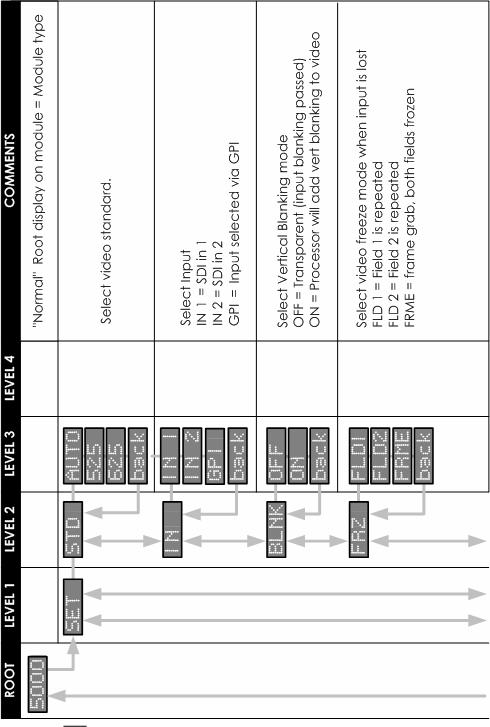
16 Using the Local Display Menus Making local adjustments to the module is done using the multifunction switch and the integrated 4- character dot matrix display (figure 3). The menu system is layered, and navigation through the system is done using the UP and DOWN functions of the switch. ENTER is used to move between menu levels and also enter a selection. Navigation Switch Function UP DOWN ENTER Operation Move UP within a level Move down within a level Change levels / Make selection Menu Structure The Menu structure is defined in the next table, and should be used when navigating through the system. Notes / Tips. ENTER moves between Levels UP/DOWN moves between items within the level When you enter a new setting the system will jump back one level in the menu system. The back selection in the menu structure will take you back one level when selected. When an item is selected which has several setting possibilities the first value displayed will be the value currently stored in the system. The order of the available settings for any menu item in the table supplied does not represent the order he settings will actually be displayed. If left unattended, the menu will default to the root display after a preset timeout. Page 16
17 Page 17
18 Page 18
19 ADJ RSET bac k PED OF F S AT O F F M AN bac k M AN bac k B R I O F F H UE O F F M AN bac k M AN bac k bac k YES NO Reset to neutral level Enter luminance offset -10%...+10% Reset to neutral level Enter saturation 50%...150% Reset to neutral level Enter brightness (Y gain) 50%...150% Reset to neutral level Enter hue -30%...+30% Restore factory defaults Page 19
20 Factory Preset Condition The P VD 5000 G is delivered programmed and preset for the following mode of operation: Mode Frame Synchronizer Input Input 1 Standard Auto Blanking (VBI) Transparent Freeze mode Frame Reference External Line delay (CH A) 0000 Pixel delay (CH A) 0000 Frame delay (CHA) 0000 Line delay (CH B) 0000 Pixel delay (CH B) 0000 Frame delay (CHB) 0000 Pedestal default (OFF) Saturation default (OFF) Brightness default (OFF) Hue default (OFF) If this is the mode of operation required, then no adjustments are necessary. These settings can be recalled at any time by selecting reset from the menu system. Auto Store If no parameters are changed for 10 seconds then the current settings will be written into flash memory automatically, this can be seen by the alarm LED flashing yellow four times. Page 20
21 Alarm/LED Status Indicators The P VD 5000 G module has integral LED indicators, which serve as alarm and status indication for the module. Function is described below. Status Indicators 3 status LED`s are provided on the PCB, LED 1, LED 2, LED 3 (Figure 2) LED Color Indication Green Yellow Red Green Yellow Red Green Yellow Red Ref = 525/60 Hz Ref = 625/50 Hz External Ref = invalid or missing SDI 1 Input = 525/60 Hz SDI 1 Input = 625/50 Hz SDI 1 Input = invalid or missing SDI 2 Input = 525/60 Hz SDI 2 Input = 625/50 Hz SDI 2 Input = invalid or missing Alarm Indicator There is also a single alarm LED on the lower edge of the module LED 4. This is visible through the card frame front cover and provides a general indication of the module status. LED Color Green Red Indication Normal Operation Board Failure LED OFF indicates power is lost, or there is a power supply fault. Page 21
 Once the specific module has been selected on the control system there")
22 Locate Function For larger systems which may have multiple cards of the same type in a single rack, or multiple rack systems on a large central control system we have added a useful utility which will help to visually locate a suspect module quickly (When used in conjunction with the optional control system and software) Once the specific module has been selected on the control system there is a locate button on the top of the GUI: Locate Function in Control System When Locate is selected the status indicator on the GUI and the alarm LED will flash yellow in the following continuous sequence. 3 short flashes. Pause. 3 short flashes Use of the locate function will not interfere with the normal operation of the module. For more details on this feature please check the documentation supplied with the controller software. Page 22
23 Specifications (P VD 5000 G) Video Inputs Signal Input Impedance Connection Cable Length Return Loss Reference Input Signal Detection Connection Impedance Outputs Signal Connection Impedance Return Loss Jitter Delay Output Signal Connection Operating Modes Line Frame Performance Adjustment range Control Electrical Specifications 2 x SDI inputs - selectable (SMPTE 259M-C) 75 Ohms BNC 250 m; Belden 8281 (270Mbit/s) > 15dB (270 MHz) Composite analog sync, 525/60Hz or 625/50Hz Automatic BNC 75 Ohms 2 x SDI (SMPTE 259M-C) BNC 75 Ohms > 15dB (270 MHz) < 0.2 ui TTL pulse duty cycle = delay from input to output BNC, 75 Ohm Line Synchronizer Frame Synchronizer Min delay to 4 frames max in 37ns increments; Min Delay: Frame Synch Mode: 1 Frame Line Synch Mode: 1 µs Local display and multi-function switch and via remote when using a rack controller and LYNX control software. Operating Voltage 12 VDC Power Consumption 7 W Safety IEC 950/ EN 60950/VDE 0805 Mechanical Size Weight Ambient Temperature Humidity 283mm x 78mm Card module 120g, connection panel 50g 5 C to 35 C Maintaining specifications Max 90% non condensing Supplied Accessories Documentation P VD 5000 G Reference Manual Page 23
24 Available Options Below is a list of related products for the P VD 5000 G CardModule. Please refer to product brochures or our web site for more detailed information. Model R FR 5010 Description Series 5000 Rack Frame (empty) with single power supply R PS 5010 Redundant power supply for the R FR 5010 Card Frame R CT 5020 R CT 5010 Rack controller for the R FR 5010 Card Frame Rack Bus Extension for the R FR 5010 Card Frame. In combination with R CT 5020 Parts List Due to the very dense design and miniature surface mount technology the module is not field serviceable. The information for a replacement assembly is below. P VD 5000 G CardModule (complete) Description Media Processor Model Number P VD 5000 G Part Number Sub Assemblies: P VD 5000 G Processing Board only (BS 5012 E) Part Number Rear Connection Panel for P VD 5000 G (MA 5020) Part Number Page 24
25 Service Reference Manual P VD 5000 G Version 1.0 If you are experiencing problems, or have questions concerning your P VD 5000 G CardModule please contact your local distributor for assistance. We offer a fixed cost service exchange program for defective Series 5000 CardModules out of Warranty. Please contact your distributor or check our web site for details on this program. More detailed information and product updates may be available on our web site: You will also find links to contact us directly for assistance. Page 25

26 Contact Information Please contact your local distributor; this is your local and fastest method for obtaining support and sales information. LYNX Technik can be contacted directly using the information below. Address LYNX Technik AG Brunnenweg 3 D Weiterstadt Germany. Phone + 49 (0) Fax + 49 (0) Website info@lynx-technik.com LYNX Technik manufactures a complete range of high quality modular products for broadcast and Professional markets, please contact your local representative or visit our web site for more product information. Page 26
27 This page is intentionally left blank Page 27
28 Notes Page 28
CardModule. Reference Manual. Series P VD 5005 G Video Media Processor (Frame Synch with Audio Processing for embedded Audio) Version 1.
 Version 1.") Version 1.4 Reference Manual P VD 5005 G Video Media Processor (Frame Synch with Audio Processing for embedded Audio) Series 5000 CardModule LYNX Technik AG Brunnenweg 3 D-64331 Weiterstadt Germany www.lynx-technik.com
Version 1.4 Reference Manual P VD 5005 G Video Media Processor (Frame Synch with Audio Processing for embedded Audio) Series 5000 CardModule LYNX Technik AG Brunnenweg 3 D-64331 Weiterstadt Germany www.lynx-technik.com
CardModule. Reference Manual. Series C DA Channel SDI to CVBS Converter. Version 1.0
 Reference Manual C DA 5005 5 Channel SDI to CVBS Converter Version 1.0 Series 5000 CardModule LYNX Technik AG Brunnenweg 3 D-64331 Weiterstadt Germany www.lynx-technik.com Information in this document
CardModule. Reference Manual. Series C AD 5122 CVBS to SDI Converter & Frame Synchronizer. Version 1.0
 Version 1.0 Reference Manual C AD 5122 CVBS to SDI Converter & Frame Synchronizer Series 5000 CardModule LYNX Technik AG Brunnenweg 3 D-64331 Weiterstadt Germany www.lynx-technik.com Information in this
MiniModules. Reference Manual. Series D VD 3620 Dual HD / SD Digital Video Distribution Amplifier
 Reference Manual D VD 3620 Dual HD / SD Digital Video Distribution Amplifier Series 3000 MiniModules LYNX Technik AG Brunnenweg 3 64331 Weiterstadt Germany www.lynx-technik.com Information in this document
Reference Manual D VD 5820
 Reference Manual D VD 5820 3GBit/s Dual SDI/ASI Distribution Amplifier Revision 1.0 May 2010 This Manual Supports Device Revisions: D VD 5820 Firmware Revision 377 Control System GUI Release 4.7.3 Information
MiniModules. Reference Manual. Series D VA 3120 Dual Analog Video Distribution Amplifier
 Reference Manual D VA 3120 Dual Analog Video Distribution Amplifier Series 3000 MiniModules LYNX Technik AG Brunnenweg 3 64331 Weiterstadt Germany www.lynx-technik.com Information in this document is subject
MiniModules. Reference Manual. Series C DA 3000 SDI to Analog Video Converter
 Reference Manual C DA 3000 SDI to Analog Video Converter Series 3000 MiniModules LYNX Technik AG Brunnenweg 3 64331 Weiterstadt Germany www.lynx-technik.com Information in this document is subject to change
MiniModules. Reference Manual. Series C AD Bit CVBS / YC to SDI Converter. Ver 1.1 Ver
 Reference Manual C AD 3100 12 Bit CVBS / YC to SDI Converter Ver 1.1 Ver Series 3000 MiniModules LYNX Technik AG Brunnenweg 3 64331 Weiterstadt Germany www.lynx-technik.com Information in this document
MiniModules. Reference Manual. Series P MX 3312/3313 D Dual Analog Audio Multiplexer. LYNX Technik AG
 Reference Manual P MX 3312/3313 D Dual Analog Audio Multiplexer Series 3000 MiniModules LYNX Technik AG P MX 3312 D SDI IN n.c. SDI out 1 SDI out 2 SDI out 3 Audio in SDI out 4 Dual Analog Audio Multiplexer
Reference Manual D VA 5718 L D VA 5724
 LYNXTechnik AG Broadcast Television Equipment Reference Manual D VA 5718 L 1>8 Analog Video Distribution Amplifier with passive loop out D VA 5724 Dual 1>4 Analog Video Distribution Amplifier Revision
Reference Manual D VD 5602
 Reference Manual D VD 5602 Dual HD > SD Digital Down Converter Revision 2.0 November 2009 This Manual Supports Device Revisions: D VD 5602 Firmware Revision 334 Control System GUI Release 4.6.6 Information
yellobrik Reference Manual P MV G/HD/SD Quad Split Multiviewer Revision 1.1 March 2016 Broadcast Television Equipment
 yellobrik Reference Manual P MV 1841 3G/HD/SD Quad Split Multiviewer Revision 1.1 March 2016 LYNXTechnik AG Broadcast Television Equipment This Manual Supports Device Revisions: P MV 1841 Firmware Revision
RD10MD Dual HD to SD Down Converter R-series Card Module
 RD0MD Dual HD to SD Down Converter R-series Card Module User Manual March 30, 2006 P/N 0665-00 2 Trademarks AJA, Io, and Kona are trademarks of AJA Video, Inc. All other trademarks are the property of
D10C2 10-bit Serial Digital to Composite/ Component Converter User Manual
 D10C2 10-bit Serial Digital to Composite/ Component Converter User Manual October 25, 2003 P/N 101640-00 2 Trademarks AJA, Io, and Kona are trademarks of AJA Video, Inc. All other trademarks are the property
Reference Manual C DX 5025
 Reference Manual C DX 5025 SDI embedded to analog Audio & Video Converter Revision 1.1 FW V342 October 2009 Information in this document is subject to change without notice. No part of this document may
Broadcast Television Equipment. Reference Manual P DM 5380 P DM 5380 O. SD / HD / 3 GBit/s Multi-format analog Audio Embedder / Deembedder
 LYNXTechnik AG Broadcast Television Equipment Reference Manual P DM 5380 P DM 5380 O SD / HD / 3 GBit/s Multi-format analog Audio Embedder / Deembedder Revision: 1.1 August 2013 This Manual Supports Device
D5CE Serial Digital Encoder
 D5CE Serial Digital Encoder User Manual December 5, 2003 P/N 101635-00 2 Trademarks AJA, Io, and Kona are trademarks of AJA Video, Inc. All other trademarks are the property of their respective holders.
R20CE 10-bit Encoder. R-series Card Module User Manual. August 25, 2003 P/N
 R20CE 10-bit Encoder R-series Card Module User Manual August 25, 2003 P/N 101646-00 2 Trademarks AJA, Io, and Kona are trademarks of AJA Video, Inc. All other trademarks are the property of their respective
Instructions. P MHz 1X/10X Passive Probe
 Instructions P2100 100 MHz 1X/10X Passive Probe 071-0774-01 071077401 Copyright Tektronix, Inc. All rights reserved. Tektronix products are covered by U.S. and foreign patents, issued and pending. Information
Reference Manual P DM 5288 B/D. SD / HD Multi-format AES Audio Embedder / Deembedder. Revision: 1.3 May 2010
 Reference Manual P DM 5288 B/D SD / HD Multi-format AES Audio Embedder / Deembedder Revision: 1.3 May 2010 This Manual Supports Device Revisions: P DM 5288 Firmware Revision 376 Control System GUI Release
VAM6800 A/D Conversion and Audio Embedder USER MANUAL
 VAM6800 A/D Conversion and Audio Embedder USER MANUAL Product Information Model: VAM6800 A/D Conversion and Audio Embedder Version: V010002 Release Date: July 19th, 2010 Company OSEE TECHNOLOGY CO., LTD.
Reference Manual P VD 5660 D P VD 5660 B
 Reference Manual P VD 5660 D P VD 5660 B Dual Channel SD/HD Multi-format Frame Synchronizer with Full Embedded and External AES Audio Support Revision 2.4 June 2010 This Manual Supports Device Revisions:
Reference Manual C DX 5624
 Reference Manual C DX 5624 SD/HD Down Converter with Embedded Audio Support and Video and Audio D/A Conversion Revision 2.0 (HW Revision 03 required) FW V325 July 2008 Information in this document is subject
DEC/DES6800 CVBS/SDI Converter USER MANUAL
 DEC/DES6800 CVBS/SDI Converter USER MANUAL Product Information Model: DEC/DES6800 CVBS/SDI Converter Version: V010000 Release Date: March 28th, 2008 Company OSEE TECHNOLOGY CO., LTD. Contact Information
PRO-ScalerHD2V HDMI to VGA & Audio Scaler Converter. User s Guide. Made in Taiwan
 PRO-ScalerHD2V HDMI to VGA & Audio Scaler Converter User s Guide Made in Taiwan Congratulations for owning a gofanco product. Our products aim to meet all your connectivity needs wherever you go. Have
8024-DSS-02 Issue 2. DSS-8024 Dual Serial Switch USER MANUAL
 8024-DSS-02 Issue 2 DSS-8024 Dual Serial Switch USER MANUAL DSS-8024 Dual Serial Switch User Manual Ross Part Number: 8024-DSS-02 Document Issue: 2 Printing Date: March 15, 2000. Printed in Canada. The
Broadcast Television Equipment. Reference Manual P VD 5840 D P VD 5840 U P VD 5840 DO P VD 5840 UO
 LYNXTechnik AG Broadcast Television Equipment Reference Manual P VD 5840 D P VD 5840 U P VD 5840 DO P VD 5840 UO Dual Channel SD/HD/3G Multi-format Frame Synchronizer with Full Embedded and External AES
PRO-ScalerV2HD VGA to HDMI & Audio Scaler Converter. User s Guide. Made in Taiwan
 VGA to HDMI & Audio Scaler Converter User s Guide Made in Taiwan Congratulations for owning a gofanco product. Our products aim to meet all your connectivity needs wherever you go. Have fun with our products!
3G/HD/SD-SDI to HDMI Converter
 3G/HD/SD-SDI to HDMI Converter Model #: 3G/HD/SD-SDI to HDMI Converter 2010 Avenview Inc. All rights reserved. The contents of this document are provided in connection with Avenview Inc. ( Avenview ) products.
Reference Manual P VD 5660 D P VD 5660 B. Dual Channel SD/HD Multi-format Frame Synchronizer with Full Embedded and External AES Audio Support
 Reference Manual P VD 5660 D P VD 5660 B Dual Channel SD/HD Multi-format Frame Synchronizer with Full Embedded and External AES Audio Support Revision 2.7 February 2014 This Manual Supports Device Revisions:
USER INSTRUCTIONS MODEL CSI-200 COAXIAL SYSTEM INTERFACE
 USER INSTRUCTIONS MODEL CSI-200 COAXIAL SYSTEM INTERFACE 9350-7676-000 Rev B, 5/2001 PROPRIETARY NOTICE The RTS product information and design disclosed herein were originated by and are the property of
8 Port HD/SD-SDI Switch
 8 Port HD/SD-SDI Switch User s Guide Models SW-HDSDI-8X1 2008 Avenview Inc. All rights reserved. The contents of this document are provided in connection with Avenview Inc. ( Avenview ) products. Avenview
8 Port HD/SD-SDI Video Switch with 2 Port Splitter
 8 Port HD/SD-SDI Video Switch with 2 Port Splitter User s Guide Models SW-HDSDI-8X2 2008 Avenview Inc. All rights reserved. The contents of this document are provided in connection with Avenview Inc. (
Broadcast Television Equipment. Reference Manual P DM 5290 D P DM 5290 U
 LYNXTechnik AG Broadcast Television Equipment Reference Manual P DM 5290 D P DM 5290 U SD / HD / 3 GBit/s Multi-format AES Audio & Data Embedder / Deembedder & Shuffler Revision: 1.1 August 2013 This Manual
Broadcast Television Equipment. Reference Manual P DM 5240 D P DM 5240 U. SD/HD/3G Multi-format digital Audio Embedder / Deembedder
 LYNXTechnik AG Broadcast Television Equipment Reference Manual P DM 5240 D P DM 5240 U SD/HD/3G Multi-format digital Audio Embedder / Deembedder Revision 2.0 February 2015 This Manual Supports Device Revisions:
AES-402 Automatic Digital Audio Switcher/DA/Digital to Analog Converter
 Broadcast Devices, Inc. AES-402 Automatic Digital Audio Switcher/DA/Digital to Analog Converter Technical Reference Manual Broadcast Devices, Inc. Tel. (914) 737-5032 Fax. (914) 736-6916 World Wide Web:
User Manual rev: Made in Taiwan
 CV-500S HDMI to Component/CVBS & Audio Scaler Converter User Manual rev: 131218 Made in Taiwan The CV-500S HDMI to Component/CVBS & Audio Scaler Converter has been tested for conformance to safety regulations
SP x6 12G/6G/3G/HD/SD-SDI Distribution Amplifier with Reclocking. User Manual. rev: Made in Taiwan
 SP-3026 1x6 12G/6G/3G/HD/SD-SDI Distribution Amplifier with Reclocking User Manual rev: 160815 Made in Taiwan Safety and Notice The SP-3026 1x6 12G/6G/3G/HD/SD-SDI Distribution Amplifier with Reclocking
AES-404 Digital Audio Switcher/DA/Digital to Analog Converter
 Broadcast Devices, Inc. AES-404 Digital Audio Switcher/DA/Digital to Analog Converter Technical Reference Manual Broadcast Devices, Inc. Tel. (914) 737-5032 Fax. (914) 736-6916 World Wide Web: www.broadcast-devices.com
HDMI-8x8. MicroQ User Manual APANTAC LLC, 7556 SW BRIDGEPORT ROAD, PORTLAND, OR TEL: , FAX:
 HDMI-8x8 MicroQ User Manual COPYRIGHT and TRADEMARK All rights reserved by APANTA LCC, Porland, Oregon, USA. No part of this document may be reproduced in any form or by any means without written permission
Model /29S RF Splitter
 Instruction Manual Model 1584-29/29S RF Splitter March 2013, Rev. 0 LNB VOLTAGE A B MODEL 1584 COMBINER CROSS TECHNOLOGIES INC. GND+DC ON Data, drawings, and other material contained herein are proprietary
TC Mbps - 622Mbps FIBER OPTIC MODE CONVERTER/REPEATER (Rev A0.1) User's Manual
 User's Manual") TC3004 50Mbps - 622Mbps FIBER OPTIC MODE CONVERTER/REPEATER (Rev A0.1) MODEL: S/N: DATE: Notice! Although every effort has been made to insure that this manual is current and accurate as of date of publication,
TC3004 50Mbps - 622Mbps FIBER OPTIC MODE CONVERTER/REPEATER (Rev A0.1) MODEL: S/N: DATE: Notice! Although every effort has been made to insure that this manual is current and accurate as of date of publication,
Kramer Electronics, Ltd. USER MANUAL. Models: 6808, SDI-AES De-Embedder 6809, SDI-AES Embedder
 Kramer Electronics, Ltd. USER MANUAL Models: 6808, SDI-AES De-Embedder 6809, SDI-AES Embedder Contents Contents 1 Introduction 1 2 Getting Started 1 3 Overview 1 3.1 About the 6808 SDI-AES De-Embedder
SAC6840N 2X1 Switcher USER MANUAL
 SAC6840N 2X1 Switcher USER MANUAL Product Information Model: SAC6840N 2X1 Switcher Version: V010001 Release Date: June 30th, 2008 Company OSEE TECHNOLOGY CO., LTD. Contact Information Address: No.22 Building,
3GSDI Audio Embedder
 1080P 3GSDI Audio Embedder GEF-SDI-AUDE User Manual www.gefenpro.com ASKING FOR ASSISTANCE Technical Support: Telephone (818) 772-9100 (800) 545-6900 Fax (818) 772-9120 Technical Support Hours: 8:00 AM
Broadcast Television Equipment. Reference Manual C MX 5710
 LYNXTechnik AG Broadcast Television Equipment Reference Manual C MX 5710 HD/SD Analog Video to SDI Converter with Frame Synchronizer, Analog Audio Inputs and AES Ports Revision 1.0 July 2015 This Manual
CEDAR Series. To learn more about Ogden CEDAR series signal processing platform and modular products, please visit
 CEDAR Series The CEDAR platform has been designed to address the requirements of numerous signal processing modules. Easily-installed components simplify maintenance and upgrade. To learn more about Ogden
SAFETY AND NOTICE TABLE OF CONTENTS
 SAFETY AND NOTICE The VAC-12SH 3G/HD/SD-SDI to HDMI Converter has been tested for conformance to safety regulations and requirements, and has been certifi ed for international use. However, like all electronic
PRO-HDMI2HD. HDMI to SDI/3G-HD-SD Converter. User Manual. Made in Taiwan
 PRO-HDMI2HD HDMI to SDI/3G-HD-SD Converter User Manual Made in Taiwan rev.1008 103 Quality Circle, Suite 210 Huntsville, Alabama 35806 Tel: (256) 726-9222 Fax: (256) 726-9268 Email: service@pesa.com Safety
Instruction Manual. SMS 8104 Serial Digital Frame Delay
 Instruction Manual SMS 8104 Serial Digital Frame Delay 071-0545-00 First Printing: December 1998 Contacting Tektronix Customer Support Product, Service, Sales Information Voice Fax Addresses Web Site North
32 Channel CPCI Board User Manual
 0 Sections Page 1.0 Introduction 1 2.0 Unpacking and Inspection 1 3.0 Hardware Configuration 1 4.0 Board Installation 5 5.0 I/O Connections and the Front Panel 5 5.1 Front Panel Layout 5 5.2 Input and
Kramer Electronics, Ltd. USER MANUAL. Model: VM Video Component Distributor
 Kramer Electronics, Ltd. USER MANUAL Model: VM-1045 Video Component Distributor Contents Contents 1 Introduction 1 2 Getting Started 1 2.1 Quick Start 1 3 Overview 3 4 Your VM-1045 Video Component Distributor
8020A-D-DVB-03-MNL Issue 3. DVB-8020A-D Digital Video Buffer Delay Version USER MANUAL
 8020A-D-DVB-03-MNL Issue 3 DVB-8020A-D Digital Video Buffer Delay Version USER MANUAL DVB-8020A-D Digital Video Buffer Delay Version User Manual Ross Part Number: 8020A-D-DVB-03-MNL Document Issue: 3 Printing
DA8-T DA8-T MANUAL
 J C F A U D I O MANUAL 1.0 contact@jcfaudio.com www.jcfaudio.com Safety Information Do not repair, modify, service this device except in the manner in which it is described in this manual. Doing so can
SAWM60 AUDIO/VIDEO MODULATOR
 SAWM60 LIMITED WARRANTY Holland Electronics LLC, warrants that the product enclosed with this Limited Warranty statement will conform to the manufacturer s specifications and be free of defects in the
instruction manual video mixer model 614gs & 614g
 instruction manual video mixer model 614gs & 614g s/n COLORADO VIDEO, INC BOULDER, COLORADO February 2003 WARNING This equipment generates, uses and can radiate radio frequency energy and if not installed
APSPB PUSH BUTTON ZERO Installation Manual
 APSPB PUSH BUTTON ZERO Installation Manual CARDINAL SCALE MFG. CO. 8527-0579-0M Rev A 203 E. Daugherty, Webb City, MO 64870 USA Printed in USA 12/14 Ph: 417-673-4631 Fax: 417-673-2153 www.detectoscale.com
Kramer Electronics, Ltd. USER MANUAL. Models: TR-1YC, s-video Isolation Transformer TR-2YC, s-video Dual Isolation Transformers
 Kramer Electronics, Ltd. USER MANUAL Models: TR-1YC, s-video Isolation Transformer TR-2YC, s-video Dual Isolation Transformers Contents Contents 1 Introduction 1 2 Getting Started 1 2.1 Quick Start 1 3
HMA-860H AGILE MODULATOR
 HMA-860H AGILE MODULATOR LIMITED WARRANTY Holland Electronics LLC, warrants that the product enclosed with this Limited Warranty statement will conform to the manufacturer s specifications and be free
Kramer Electronics, Ltd. USER MANUAL. Model: CV / YC to SDI Converter
 Kramer Electronics, Ltd. USER MANUAL Model: 7508 CV / YC to SDI Converter Contents Contents 1 Introduction 1 2 Getting Started 1 3 Overview 1 4 Your 7508 CV / YC to SDI Converter 2 5 Using Your 7508 CV
User Manual TL-2X1-HDVC 2x1 HDMI & VGA Switcher with Control All Rights Reserved Version: TL-2X1-HDVC_160630
 User Manual TL-2X1-HDVC 2x1 HDMI & VGA Switcher with Control All Rights Reserved Version: TL-2X1-HDVC_160630 Preface Read this user manual carefully before using this product. Pictures shown in this manual
Reference Manual PTG 5610 B/D
 Reference Manual PTG 5610 B/D Multi-format SD/HDSDI Video and AES Audio Test Generator Revision 1.0 February 2008 This Manual Supports Device Revisions: PTG 5610B/D Firmware Revision 235.4.17 Control System
3G/HD/SD-SDI to HDMI Converter with Audio Extraction and Mixer
 CV-305MLR 3G/HD/SD-SDI to HDMI Converter with Audio Extraction and Mixer User Manual rev: 140509 Made in Taiwan Safety and Notice The CV-305MLR 3G/ HD/SD-SDI to HDMI Converter with Audio Extraction and
instruction manual Model 619D video dual cross hair generator s/n
 instruction manual Model 619D video dual cross hair generator s/n september 2005 WARNING This equipment generates, uses and can radiate radio frequency energy and if not installed and used in accordance
TC3005(LED/ELED/LASER) User's Manual
 User's Manual") 1. Description The gives users the ability to convert signals to format for data transmission (and vice-versa). These conversions can benefit users by extending transmission distances and/or enabling dissimilar
1. Description The gives users the ability to convert signals to format for data transmission (and vice-versa). These conversions can benefit users by extending transmission distances and/or enabling dissimilar
17 19 PROFESSIONAL LCD COLOUR MONITOR ART
 17 19 PROFESSIONAL LCD COLOUR MONITOR ART. 41657-41659 Via Don Arrigoni, 5 24020 Rovetta S. Lorenzo (Bergamo) http://www.comelit.eu e-mail:export.department@comelit.it WARNING: TO REDUCE THE RISK OF FIRE
Kramer Electronics, Ltd. USER MANUAL. Model: FC Standards Converter / TBC
 Kramer Electronics, Ltd. USER MANUAL Model: FC-4000 Standards Converter / TBC Contents Contents 1 Introduction 1 2 Getting Started 1 3 Overview 1 4 Your Standards Converter / TBC 2 4.1 Connecting the
1080P. 3GSDI Audio De-Embedder. GEF-SDI-AUDD User Manual.
 1080P 3GSDI Audio De-Embedder GEF-SDI-AUDD User Manual www.gefenpro.com ASKING FOR ASSISTANCE Technical Support: Telephone (818) 772-9100 (800) 545-6900 Fax (818) 772-9120 Technical Support Hours: 8:00
CDV07. Analog video distribution amplifier(s)
") CDV07 Analog video distribution amplifier(s) TECHNICAL MANUAL CDV07 Analog video distribution amplifier Lange Wagenstraat 55 NL-5126 BB Gilze The Netherlands Phone: +31 161 850 450 Fax: +31 161 850 499
CDV07 Analog video distribution amplifier(s) TECHNICAL MANUAL CDV07 Analog video distribution amplifier Lange Wagenstraat 55 NL-5126 BB Gilze The Netherlands Phone: +31 161 850 450 Fax: +31 161 850 499
instruction manual Model 619YY video dual vertical line generator s/n
 instruction manual Model 619YY video dual vertical line generator s/n september 2005 WARNING This equipment generates, uses and can radiate radio frequency energy and if not installed and used in accordance
1x6 3G/HD/SD-SDI Distribution Amplifier with Reclocking
 ML-1x6 1x6 3G/HD/SD-SDI Distribution Amplifier with Reclocking User Manual Made in Taiwan Safety and Notice The ML-1x6 1x6 3G/HD/SD-SDI Distribution Amplifier with Reclocking has been tested for conformance
Operation Manual 1T-TG-PCHD Analog Test Generator 1T-TG-DVI DVI Test Generator
 99 Washington Street Melrose, MA 02176 Phone 781-665-1400 Toll Free 1-800-517-8431 Visit us at www.testequipmentdepot.com Operation Manual 1T-TG-PCHD Analog Test Generator 1T-TG-DVI DVI Test Generator
PSM-003. Micro Polarization Controller/Scrambler. User Guide
 PSM-003 Micro Polarization Controller/Scrambler User Guide Version: 1.0 Date: August 23, 2012 General Photonics, Incorporated is located in Chino California. For more information visit the company's website
Crescent Walls User Manual
 HDMI-8x8 Crescent Walls User Manual COPYRIGHT and TRADEMARK All rights reserved by APANTA LCC, Porland, Oregon, USA. No part of this document may be reproduced in any form or by any means without written
Reference Manual C DX 3624
 Reference Manual C DX 3624 SD/HD Monitoring Down Converter with Embedded Audio Support and Video and Audio D/A Conversion Revision 1.2 December 2006 Information in this document is subject to change without
WXL-2F, WXL-1F, WXL-2M, WXL-1M
 Kramer Electronics, Ltd. USER MANUAL Wall Plate (WXL) Series Multifunctional Passive Wall Plates: WXL-1FM, WXL-2F, WXL-1F, WXL-2M, WXL-1M Contents Contents 1 Introduction 1 2 Getting Started 1 3 Overview
Instruction Manual Model # Block Upconverter
 Instruction Manual Model 2115-278# Block Upconverter August 2018, Rev. A MODEL 2115 UPCONVERTER CROSS TECHNOLOGIES INC. EXT 10MHZ ALARM POWER Data, drawings, and other material contained herein are proprietary
User Manual TL-2X1-HDV 2x1 HDMI & VGA Switcher All Rights Reserved Version: TL-2X1-HDV_160630
 User Manual TL-2X1-HDV 2x1 HDMI & VGA Switcher All Rights Reserved Version: TL-2X1-HDV_160630 Preface Read this user manual carefully before using this product. Pictures shown in this manual are for reference
Kramer Electronics, Ltd. USER MANUAL. Model: VP-100. VGA/XGA to RGBHV Converter
 Kramer Electronics, Ltd. USER MANUAL Model: VP-100 VGA/XGA to RGBHV Converter Contents Contents 1 Introduction 1 2 Getting Started 1 2.1 Quick Start 1 3 Overview 3 4 Your VP-100 VGA/XGA to RGBHV Converter
AWT150C/AWT150CS/ AWT151C CCD Camera
 AWT150C/AWT150CS/ AWT151C CCD Camera ISSUED OCTOBER 2018 WARNING Failure to follow all instructions and safety precautions in this manual, in the vehicle and body manufacturers' manuals and on the safety
AES Channel Digital/Analog Audio Switcher/DA/Digital to Analog Converter
 Broadcast Devices, Inc. AES-408 8 Channel Digital/Analog Audio Switcher/DA/Digital to Analog Converter Technical Reference Manual Broadcast Devices, Inc. Tel. (914) 737-5032 Fax. (914) 736-6916 World Wide
HMV160 High-definition Multi-viewer Display Processor USER MANUAL
 HMV160 High-definition Multi-viewer Display Processor USER MANUAL Product Information Model: HMV160 High-definition Multi-viewer Display Processor Version: V010001 Release Date: January 1st, 2011 Company
TR6102HD HDTV/DVD/COMPONENT VIDEO TO RGBHV TRANSCODER USER S GUIDE
 MANUAL PART NUMBER: 400-0031-003 PRODUCT REVISION: 1 HDTV/DVD/COMPONENT VIDEO TO RGBHV TRANSCODER USER S GUIDE INTRODUCTION Thank you for your purchase of the Transcoder. We are certain that you will find
Model 1421 Distribution Amplifier
 Model 1421 Distribution Amplifier Installation and Operating Instructions The 1421 Distribution Amplifier provides four independent, wide bandwidth outputs from one video input. The unit is color compatible
User Guide. Centrex Recording Interface
 User Guide Centrex Recording Interface Table of Contents Introduction... 2 The Meridian Business Set... 3 Key Numbering Plan (18 button add-on)... 4 Key Numbering Plan (36 button add-on)... 5 Key Numbering
Perle Fast Ethernet Fiber to Fiber Media Converter Module. Installation Guide. P/N (Rev D)
") Perle Fast Ethernet Fiber to Fiber Media Converter Module Installation Guide C-100MM-XXXXX CM-100MM-XXXXX Unmanaged Module Managed Module P/N 5500313-10 (Rev D) Overview This document contains instructions
Perle Fast Ethernet Fiber to Fiber Media Converter Module Installation Guide C-100MM-XXXXX CM-100MM-XXXXX Unmanaged Module Managed Module P/N 5500313-10 (Rev D) Overview This document contains instructions
PRO-CoaxExt HDMI extender over Coaxial cable with bi-directional IR User s Guide
 HDMI extender over Coaxial cable with bi-directional IR User s Guide Transmitter Receiver Made in Taiwan Congratulations for owning a gofanco product. Our products aim to meet all your connectivity needs
HCC6830N Series. HD/SD Digital Video Signal Cross Converter. User Manual
 HCC6830N Series HD/SD Digital Video Signal Cross Converter User Manual Product Information Model: HCC6830N Series HD/SD Digital Video Signal Cross Converter Version: V010001 Release Date: August 21th,
SD/HD-SDI 1 to 2 Distribution Amplifier VCF-1002DA-P
 User Manual SD/HD-SDI 1 to 2 Distribution Amplifier VCF-1002DA-P NOTE: The casing design is subject to change without notice. Our SD/HD/3G-SDI Distribution Amplifier is a 1 in, 2 out distribution and extender
Cablesson HDelity 7.1ch Audio Extractor & Mixer. User Manual
 Cablesson HDelity 7.1ch Audio Extractor & Mixer User Manual All rights reserved - CABLESSON All rights reserved - CABLESSON ! SAFETY AND NOTICE The Cablesson HDelity HDMI 7.1ch Audio Extractor and Mixer
LEVEL ADJUST POWER Shiloh Road Alpharetta, Georgia (770) FAX (770) Toll Free
 FAX (770) Toll Free") Instruction Manual Model 1200-75 Amplifier August 2012, Rev. A LEVEL ADJUST POWER MODEL 1200 AMPLIFIER CROSS TECHNOLOGIES, INC. Data, drawings, and other material contained herein are proprietary to Cross
Instruction Manual Model 1200-75 Amplifier August 2012, Rev. A LEVEL ADJUST POWER MODEL 1200 AMPLIFIER CROSS TECHNOLOGIES, INC. Data, drawings, and other material contained herein are proprietary to Cross
USERS GUIDE ASP-VTHS. VGA & Audio to HDMI Scaler Converter. Manual Number:
 USERS GUIDE ASP-VTHS VGA & Audio to HDMI Scaler Converter i Manual Number: 131120 User Guide SAFETY INSTRUCTIONS Please review the following safety precautions. If this is the first time using this model,
12G/6G/3G/HD/SD-SDI over Single mode SFP-type Fiber Optic Extender Immune to Pathological. User Manual. rev: Made in Taiwan
 EX-36K 12G/6G/3G/HD/SD-SDI over Single mode SFP-type Fiber Optic Extender Immune to Pathological User Manual rev: 170218 Made in Taiwan Safety and Notice The EX-36K 12G/6G/3G/HD/SD-SDI over Single mode
Kramer Electronics, Ltd. USER MANUAL. Model: FC Analog Video to SDI Converter
 Kramer Electronics, Ltd. USER MANUAL Model: FC-7501 Analog Video to SDI Converter Contents Contents 1 Introduction 1 2 Getting Started 1 3 Overview 2 4 Your Analog Video to SDI Converter 3 5 Using Your
Model Number Structure
 Cycle Control Units CSM DS_E_7_1 Refer to Safety Precautions for All Power Controllers. Used in Combination with the to Enable High-precision Temperature Control Use cycle control to achieve power control
HDX6811N/HDX6812N High-definition Digital Audio De-embedder USER MANUAL
 HDX6811N/HDX6812N High-definition Digital Audio De-embedder USER MANUAL Product Information Model: HDX6811N/HDX6812N High-definition Digital Audio De-embedder Version: V010001 Release Date: May 22th, 2012
CH1 CH2 CH3 CH4. Master /Fade CH5. 600s CH6. 60s SC1 SC2 SC4 SC3 SC5. SC6 Off/Pro. AL Fade 6 Pro. User guide
 1 1 CH1 CH2 1 1 CH4 CH 1 CH3 6s Master /Fade CH6 1 SC1 6s SC4 SC2 SC SC3 SC6 Off/Pro AL Fade 6 Pro User guide CONTENTS INTRODUCTION...2 Welcome 2 Safety 2 Supplied items 3 INSTALLATION...4 Mounting 4
LEVEL ADJUST POWER Shiloh Road Alpharetta, Georgia (770) FAX (770) Toll Free
 FAX (770) Toll Free") Instruction Manual Model 1200-07 Amplifier September 2010 Rev A MONITOR J1 LEVEL ADJUST POWER MODEL 1200 AMPLIER CROSS TECHNOLOGIES, INC. Data, drawings, and other material contained herein are proprietary
Instruction Manual Model 1200-07 Amplifier September 2010 Rev A MONITOR J1 LEVEL ADJUST POWER MODEL 1200 AMPLIER CROSS TECHNOLOGIES, INC. Data, drawings, and other material contained herein are proprietary
SK2002DA SIDEKICKER 1-IN, 2-OUT VGA-UXGA DISTRIBUTION AMPLIFIER CABLE USER S GUIDE DISTRIBUTION AMPLIFIERS
 MANUAL PART NUMBER: 400-0152-001 PRODUCT REVISION: 0 SK2002DA SIDEKICKER 1-IN, 2-OUT VGA-UXGA DISTRIBUTION AMPLIFIER CABLE USER S GUIDE TABLE OF CONTENTS Page PRECAUTIONS / SAFETY WARNINGS...2 GENERAL...2
Garmin GC 10 Marine Camera Instructions
 Garmin GC 10 Marine Camera Instructions FCC Compliance This device complies with part 15 of the FCC Rules. Operation is subject to the following two conditions: (1) this device may not cause harmful interference,