AVR x 110W 7.1 CHANNEL A/V RECEIVER
|
|
|
- Sherman Bishop
- 6 years ago
- Views:
Transcription

1 AVR x 110W 7.1 CHANNEL A/V RECEIVER SERVICE MANUAL CONTENTS ESD WARNING.2 LEAKAGE TESTING BASIC SPECIFICATIONS..4 FEATURES FRONT PANEL CONTROLS REAR PANEL CONNECTIONS...10 REMOTE CONTROL FUNCTIONS.14 INSTALLATION/CONNECTIONS OPERATION TROUBLESHOOTING GUIDE PROCESSOR RESET...29 UNIT EXPLODED VIEW...30 EXPLODED VIEW PARTS LIST..31 BLOCK DIAGRAM.. 33 CIRCUIT DESCRIPTION DC OFFSET/IDLE CURRENT ADJ.45 BULLETIN HK TECH TIP HKTT ELECTRICAL PARTS LIST..51 SEMICONDUCTOR PINOUTS 70 PCB DRAWINGS SCHEMATICS 146 WIRING DIAGRAM PACKAGING PARTS LIST...158, Inc. 250 Crossways Park Dr. Woodbury, New York Rev0 3/2005
2 Some semiconductor (solid state) devices can be damaged easily by static electricity. Such components commonly are called Electrostatically Sensitive (ES) Devices. Examples of typical ES devices are integrated circuits and some field effect transistors and semiconductor "chip" components. The following techniques should be used to help reduce the incidence of component damage caused by static electricity. 1. Immediately before handling any semiconductor component or semiconductor-equipped assembly, drain off any electrostatic charge on your body by touching a known earth ground. Alternatively, obtain and wear a commercially available discharging wrist strap device, which should be removed for potential shock reasons prior to applying power to the unit under test. 2. After removing an electrical assembly equipped with ES devices, place the assembly on a conductive surface such as aluminum foil, to prevent electrostatic charge build-up or exposure of the assembly. 3. Use only a grounded-tip soldering iron to solder or unsolder ES devices. 4. Use only an anti-static solder removal device. Some solder removal devices not classified as "anti-static" can generate electrical charges sufficient to damage ES devices. 5. Do not use freon-propelled chemicals. These can generate electrical change sufficient to damage ES devices. 6. Do not remove a replacement ES device from its protective package until immediately before you are ready to install it. (Most replacement ES devices are packaged with leads electrically shorted together by conductive foam, aluminum foil or comparable conductive material.) 7. Immediately before removing the protective material from the leads of a replacement ES device, touch the protective material to the chassis or circuit assembly into which the device will be installed. CAUTION : Be sure no power is applied to the chassis or circuit, and observe all other safety precautions. 8. Minimize bodily motions when handling unpackaged replacement ES devices. (Otherwise harmless motion such as the brushing together or your clothes fabric or the lifting of your foot from a carpeted floor can generate static electricity sufficient to damage an ES devices. Each precaution in this manual should be followed during servicing. Components identified with the IEC symbol in the parts list are special significance to safety. When replacing a component identified with, use only the replacement parts designated, or parts with the same ratings or resistance, wattage, or voltage that are designated in the parts list in this manual. Leakage-current or resistance measurements must be made to determine that exposed parts are acceptably insulated from the supply circuit before retuming the product to the customer.
3 SAFETY PRECAUTIONS The following check should be performed for the continued protection of the customer and service technician. LEAKAGE CURRENT CHECK Measure leakage current to a known earth ground (water pipe, conduit, etc.) by connecting a leakage current tester between the earth ground and all exposed metal parts of the appliance (input/output terminals, screwheads, metal overlays, control shaft, etc.). Plug the AC line cord of the appliance directly into a 120V AC 60Hz outlet and turn the AC power switch on. Any current measured must not exceed o.5ma. Device under test Leakage current tester Reading should not be above 0.5mA Test all exposed metal surfaces Also test with plug reversed (Using AC adapter plug as required) Earth ground AC Leakage Test ANY MEASUREMENTS NOT WITHIN THE LIMITS OUTLINED ABOVE ARE INDICATIVE OF A POTENTIAL SHOCK HAZARD AND MUST BE CORRECTED BEFORE RETURNING THE APPLIANCE TO THE CUSTOMER. 3
4 TM AVR7300 AVR 7300 TECHNICAL SPECIFICATIONS Audio Section Stereo Mode Continuous Average Power (FTC) 125 Watts per channel, 20Hz <0.07% THD, both channels driven into 8 ohms Seven-Channel Surround Modes Power per Individual Channel Front L&R channels: 110 Watts per <0.07% THD, 20Hz 20kHz into 8 ohms Center channel: 110 <0.07% THD, 20Hz 20kHz into 8 ohms Surround (L & R Side, L & R back) channels: 110 Watts per <0.07% THD, 20Hz 20kHz into 8 ohms High Instantaneous Current Capability (HCC) +75amps Input Sensitivity/Impedance Linear (High-Level) 200mV/47k ohms Signal-to-Noise Ratio (IHF-A) 100dB Frequency (+0dB/ 3dB) 10Hz 100kHz Surround System Adjacent Channel Separation Pro Logic I/II/IIx 40dB Dolby Digital 55dB DTS 55dB Transient Intermodulation Distortion (TIM) Slew Rate Unmeasurable 40V/µSec FM Tuner Section Frequency Range MHz Usable Sensitivity IHF 1.3µV/13.2dBf Signal-to-Noise Ratio Mono/Stereo 70/68dB Distortion Mono/Stereo 0.2/0.3% Stereo Separation 1kHz Selectivity ±400kHz, 70dB Image Rejection 80dB IF Rejection 90dB AM Tuner Section Frequency Range kHz Signal-to-Noise Ratio 45dB Usable Sensitivity Loop 500µV Distortion 1kHz, 50% Mod 0.8% Selectivity ±10kHz, 30dB Video Section Television Format Input Level/Impedance Output Level/Impedance Video Frequency Response (Composite and S-Video) Video Frequency Response (Component Video) NTSC 1Vp-p/75 ohms 1Vp-p/75 ohms 10Hz 8MHz ( 3dB) 10Hz 100MHz ( 3dB) General Power Requirement AC 120V/60Hz Power Consumption Standby: 8.9W Idle: 130W Max: 1360W (7 channels driven) Dimensions Product Shipping Width 17.3" (440mm) 23" (583mm) Height 7.6" (192mm) 12.7" (323mm) Depth 20.5" (520mm) 24.7" (626mm) Weight 55 lb (24.9kg) 69.3 lb (31.5kg) Depth measurement includes knobs, buttons and terminal connections. Height measurement includes feet and chassis. All features and specifications are subject to change without notice. Harman Kardon, Power for the Digital Revolution and Logic 7 are registered trademarks of Harman International Industries, Incorporated. is a trademark of Harman International Industries, Incorporated (patent no. 5,386,478). * Trademarks of Dolby Laboratories. DTS, DTS Surround, DTS-ES and DTS Neo:6 are registered trademarks of Digital Theater Systems, Inc. VMAx is a registered trademark of Harman International Industries, Incorporated, and is an implementation of Cooper Bauck Transaural Stereo under patent license. HDCD system manufactured under license from Pacific Microsonics, Inc. This product is covered by one or more of the following: in the USA: 5,479,168; 5,638,074; 5,640,161; 5,808,574; 5,838,274; 5,854,600; 5,864,311; 5,872,531; and in Australia: Other patents pending. A-BUS and A-BUS Ready are registered trademarks of Leisure Tech Electronics Pty Ltd Australia. TiVo is a registered trademark of TiVo, Inc. Replay TV is a registered trademark of Digital Networks North America, Inc. Faroudja, DCDi and DCDi by Faroudja are registered trademarks of Genesis Microchip, Inc. 4 AVR 7300 TECHNICAL SPECIFICATIONS 59
5 AVR7300 FEATURES OUTPUT POWER(STEREO) 125W x 2 OUTPUTS OUTPUT POWER(SURROUND) 110W x 7 Pre-Outs Hz-20kHz, 8 Ohms, 0.07%THD Yes Tape Rear All Channels Driven Yes Video 1 Rear High Current Capability Yes Video 2 Rear All-Discrete Amplifier Circuitry Yes Audio/Video Outputs, Switchable Front Dual Power Supplies, Driver and Output Stages Yes Video Monitor Rear AUDIO DSP SECTION Digital Outputs (Rear) 1 Coax, 1 Optical Dolby Digital Yes Digital Outputs (Front) 1 Coax, 1 Optical Dolby Pro Logic 2 Yes DIGITAL INPUTS Dolby Digital Ex 6.1 Yes Optical, Rear 3 Dolby Headphone Yes Coax, Rear 3 Dolby Virtualizer Yes Optical, Front 1 DTS, 5.1 Yes Coax, Front 1 DTS, 6.1 Discrete Yes GENERAL FEATURES DTS NEO 6 Yes On-Screen Display Composite, S, Component DTS 96/24 Yes Input Titling Yes VMAx, 2 Modes Near & Far Yes FL Display User ICON Logic 7, Cinema & Music 5.1, 7.1 Remote In/Out Yes Logic 7, 5.1 & 7.1 Cinema & Music Yes RS Way HDCD Decoding Yes Port for Flash Upgrade RS 232 MP 3 Decoding Yes A-Buss Ready Yes, 2 5 Channel Stereo Yes IEC Detachable AC Cord Yes 7 Channel Stereo Yes Speaker Binding Posts w/banana Jack Compatibility Yes Hall 1 Yes Thermal Controlled Air Cooling Hall 2 Yes Smart Fan Control System Theater Yes Multiroom Audio Yes Quadruple X-Over System Yes Multiroom Video Yes DVD Audio Bass Management Capability Yes REMOTE CONTROL Sampling Upconversion to 96kHz Yes # of Devices 8 DSP Processor CS49400 Preprogrammable Yes D/A Converters 192kHz/24 Bit Yes Learning Yes Flash Upgradeable Yes EZ Set Yes VIDEO DSP SECTION LCD Yes S > Composite Downconversion Yes Backlit Yes Video Scaler/Enhancer Faroujda 2300 Plugin Video Test Signals, Color Bars Yes AUDIO INPUTS AM/FM Yes CD Yes Tape Yes 6 (5.1) Channel Direct Yes 8 (7.1) Channel Direct Yes AUDIO/VIDEO INPUTS Video 1 Rear Video 2 Rear Video 3 Rear Video 4 Rear Video 5 Front DVD(Rear) Yes S-VHS Video Inputs/Outputs Yes Component Video Inputs/Outputs, HD TV Capable 3 In, 1 Out, 100Mhz Component Video Inputs, Configuarable Yes 5
6 FRONT-PANEL CONTROLS ^ % $ ) NOTE: To make it easier to follow the instructions that refer to this illustration, a larger copy may be downloaded from the Product Support section for this product at The following controls and indicators are available on the AVR 7300 s front panel: 1 Standby/On Button 2 Surround Mode Group Selector 3 Surround Mode Selector 4 Tuning Selector 5 Tuner Band Selector 6 Preset Stations Selector 7 Input Source Selector 8 Tuner Mode Selector 9 Front-Panel Control Door ) Volume Control! Input Speaker/Channel Input Indicators # Upper Display Line $ Lower Display Line % Surround Mode Indicators ^ Remote Sensor Window The following controls and jacks are located behind the Front-Panel Control Door 9. To open the door, gently press the left or right bottom-corner edge of the door in and gently swing the door down towards you Main Power Switch Headphone Jack Tone Mode Button Speaker Selector Button Channel Adjust Selector Digital Input Selector Delay Adjust Selector / Buttons Set/Video Button Optical 4 Digital Input Optical Digital Output Coaxial 4 Digital Input Coaxial Digital Output Video 5 Audio/Video Jacks Input/Output Indicator 6 FRONT-PANEL CONTROLS 5
7 FRONT-PANEL CONTROLS 1 Standby/On Button: When the Main Power Switch 1 is pressed in so that it is in the ON position, press this button to turn on the AVR When the unit is in the Standby mode, the switch is surrounded by amber lighting. When the unit is on, the lighting around the button is blue. 2 Surround Mode Group Selector: Press this button to select the top-level group of surround modes. Each press of the button will select one of the surround mode categories. Once the button is pressed so that the name of the desired surround mode category appears in the on-screen display and in the Lower Display Line $, press the Surround Mode Selector 3 to cycle through the individual modes available. For example, press this button to select Dolby modes, and then press the Surround Mode Selector 3 to choose from the various mode options. 3 Surround Mode Selector: Press this button to select from among the available surround mode options for the surround mode category selected. The specific modes will vary based on the number of speakers available, the surround mode category and whether the input source is digital or analog. For example, press the Surround Mode Group Selector 2 to select a category such as Dolby or Logic 7, and then press this button to see the specific mode choices that are available. For more information on mode selection, see page Tuning Selector: Press the left side of the button to tune lower-frequency stations and the right side of the button to tune higher-frequency stations. When the tuner is in the MANUAL/MONO mode, each tap of the selector will increase or decrease the frequency by one increment. When the tuner receives a strong-enough signal for adequate reception, MANUAL TUNED will appear in the Lower Display Line $ and in the on-screen display. When the tuner is in the AUTO/STEREO mode, press the button once, and the tuner will scan for a station with acceptable signal strength. When the next higher- or lower-frequency station with a strongenough signal is tuned, the frequency scan will stop and the Lower Display Line $ and the on-screen display will indicate AUTO TUNED. When an FM Stereo station is tuned, the display will read AUTO ST TUNED. See page 39 for more information on using the tuner. 5 Tuner Band Selector: Pressing this button will switch to the Tuner mode. Pressing it again will switch between the AM and FM frequency bands. (See page 39 for more information on the tuner.) 6 Preset Stations Selector: Press this button to scroll up or down through the list of stations that have been entered into the preset memory. (See page 39 for more information on tuner programming.) 7 Input Source Selector: Press this button to change the input by scrolling up or down through the list of input sources. 8 Tuner Mode Selector: Press this button to select Auto or Manual tuning. When the button is pressed so that AUTO/STEREO appears in the Upper Display Line #, the tuner will search for the next station with an acceptable signal when the Tuning Selector 5wé is pressed. When the button is pressed so that MANUAL/MONO appears in the Upper Display Line #, each press of the Tuning Selector 5wé will increase the frequency. (See page 39 for more information on using the tuner.) This button may also be used to switch between Stereo and Mono modes for FM radio reception. When weak reception is encountered, select the MANUAL/MONO tuning mode. Press and hold again to switch back to AUTO/STEREO mode. (See page 39 for more information on using the tuner.) 9 Front-Panel Control Door: To open the door so that the front-panel jacks and controls behind this door may be accessed, gently push the door down and toward you, using either lower corner of the door. ) Volume Control: Turn this knob clockwise to increase the volume, counterclockwise to decrease the volume. If the AVR 7300 is muted, adjusting the volume control will automatically release the unit from the silenced condition.! Input Indicators: One of these indicators will light to identify the currently selected input. Note that the entire list will light briefly each time the unit is turned on, as a Speaker/Channel Input Indicators: These indicators are multipurpose, indicating both the speaker type selected for each channel and the number of audio channels available. The speaker indicators light as a single outline around the speaker position indicator when a small speaker is selected and as a larger icon with three connected boxes when large speakers are selected. When only the speaker position letters appear, no speaker has been assigned to that position. (See page 26 for more information on configuring speakers.) The letters inside each box also indicate the active input channels. For standard analog inputs, only the L and R will light, indicating a stereo input. For a digital source, the indicators will light to display the channels being received at the digital input. When the letters flash, the digital input has been interrupted and an UNLOCK message may appear in the Lower Display Line $. (See page 38 for more information on the Channel Indicators.) # Upper Display Line: Depending on the unit s status, a variety of messages will appear here. In normal operation, this line will show the current input source and identify whether an analog or digital input is in use. When the tuner is selected as the input, this line will identify the station as AM or FM and show the frequency and preset number, if any. $ Lower Display Line: Depending on the unit s status, a variety of messages will appear here. In normal operation, the current surround mode will appear on this line. % Surround Mode Indicators: One of these indicators will light to show the surround mode in use. Depending on the specific combination of input sources and surround mode selected, more than one indicator may light. (See page 35 for more information.) ^ Remote Sensor Window: The sensor behind this window receives infrared signals from the remote control. Aim the remote at this area and do not block or cover it unless an external remote sensor is installed. 6 FRONT-PANEL CONTROLS 7
8 FRONT-PANEL CONTROLS NOTE: To make it easier to follow the instructions that refer to this illustration, a larger copy may be downloaded from the Product Support section for this product at The following controls and jacks are located behind the front-panel door. To open the door, place the edge of a finger on the left or right bottom edge of the panel and gently swing the door down toward you Main Power Switch Headphone Jack Tone Mode Button Speaker Selector Button Channel Adjust Selector Digital Input Selector Delay Adjust Selector / Buttons Set/Video Button Optical 4 Digital Input Optical Digital Output Coaxial 4 Digital Input Coaxial Digital Output Video 5 Audio/Video Jacks Input/Output Indicator 1 Main Power Switch: Press this switch to apply power to the AVR When the switch is pressed in, the unit is placed in a Standby mode, as indicated by the lighting around the Standby/On Button 1 turning amber. The switch MUST be pressed in to operate the unit. To turn the unit off and prevent the use of the remote control, this switch should be pressed until it pops out from the front panel so that the word OFF may be read at the top of the switch. NOTE: This switch is normally left in the ON position. 2 Headphone Jack: This jack may be used to listen to the AVR 7300 s output through a pair of headphones. Be certain that the headphones have a standard 1/4" stereo phone plug, or that you use an adapter, as needed, to convert the plug on your headphones to the 1/4" jack used on the AVR. When the headphone jack is in use, the main room speakers will automatically be turned off and the unit will output a standard stereo signal. You may also use one of the Dolby Headphone modes for an enhanced listening experience. For more information on headphone listening, see page Tone Mode Button: This button controls the tone mode settings, enabling adjustment of the bass and treble boost/cut. You may also use it to take the tone controls out of the signal path completely for flat response. The first press of the button displays a TONE MODE message in the Lower Display Line $ and in the on-screen display. To take the controls out of the signal path, press either of the / Buttons 8 until the display reads TONE OUT. To change the bass or treble settings, press the button again until the desired option appears in the Lower Display Line $ and in the on-screen display and then press either of the / Buttons 8 to enter the desired boost or cut setting. See page 35 for more information on the tone controls. 4 Speaker Selector Button: Press this button to begin the process of configuring the AVR 7300 for the type of speakers it is being used with. For complete information on configuring the speaker settings, see page Channel Adjust Selector: Press the button to begin the process of adjusting the channel level outputs using the source currently playing through your AVR. For complete information on adjusting the channel output level, see page Digital Input Selector: Press this button to begin the process of selecting a digital source for use with the currently selected input. Once the button has been pressed, use the / Buttons 8 to choose the desired input and then press the Set/Video Button 9 to enter the setting into the unit s memory. See page 35 for more information on digital audio. 8 FRONT-PANEL CONTROLS 7
9 FRONT-PANEL CONTROLS 7 Delay Adjust Selector: Press this button to begin the process of adjusting the delay settings. See page 28 for more information on delay adjustments. 8 / Buttons: When making system configuration changes using the front-panel controls, press these buttons to scroll through the available choices for the option being adjusted. 9 Set/Video Button: This button has two functions. Press it to turn the video processing circuits on or off, as indicated by FAROUDJA:ON or FAROUDJA:OFF messages in the Lower Display Line $ and semi-osd display. (See page 31 for more information on the video processing circuits.) The button is also used when making many of the configuration and setup adjustments from the front panel. When selecting a specific item to adjust, or after selecting a configuration setting with the / Buttons 8, press this button to enter the setting information to the unit s memory. 10 Optical 4 Digital Input: Connect the optical digital output of an audio or video product to this jack. 11 Optical Digital Output: Connect this jack to the optical digital audio input of a compatible digital recorder. 12 Coaxial 4 Digital Input: Connect the coaxial digital output of a digital audio product such as a portable audio player or video game to this jack. 13 Coaxial Digital Output: Connect this jack to the digital audio input of a compatible digital recorder. 14 Video 5 Input/Output Jacks: These audio/video jacks may be used as either inputs or outputs for temporary connection to video games or portable audio/video products such as camcorders and portable audio players. (See page 40 for more information on switching these jacks between an input and output.) 15 Input/Output Status Indicator: This LED indicator will normally light green to show that the frontpanel Video 5 Input/Output Jacks 14 is operating as an input. When this jack is configured for use as an output, the appropriate indicator will turn red to show that the jack may be used as an output for recording. (See page 23 for more information on configuring the front-panel jacks as outputs, rather than inputs.) 8 FRONT-PANEL CONTROLS 9
10 REAR-PANEL AUDIO CONNECTIONS ü ß œπå ƒ ñ ç å ç é î µ ø NOTE: To make it easier to follow the instructions that refer to this illustration, a larger copy may be downloaded from the Product Support section for this product at å Front Speaker Outputs Surround Speaker Outputs ç Surround Back/Multiroom Speaker Outputs Tape Outputs é Tape Inputs ƒ CD Inputs DVD Audio Inputs Video 4 Audio Inputs î Video 3 Audio Inputs Video 2 Audio Outputs Video 2 Audio Inputs Preamp Outputs µ Subwoofer Output ñ Video 1 Audio Inputs ø Multiroom Audio Outputs π Video 1 Audio Outputs œ Optical Digital Audio Output Optical Digital Audio Inputs ß Coaxial Digital Audio Output Coaxial Digital Audio Inputs ü 8-Channel Direct Audio Inputs Center Speaker Output NOTE: To assist in making the correct connections for multichannel input, output and speaker connections, all connection jacks and terminals are color-coded in conformance with the CEA standards as follows: Front Left: Front Right: Center: Surround Left: Surround Right: Surround Back Left: Surround Back Right: White Red Green Blue Gray Brown Tan Subwoofer: Purple Digital Audio: Orange Composite Video: Yellow Component Video Y : Green Component Video Pr : Red Component Video Pb : Blue 10 REAR-PANEL AUDIO CONNECTIONS 9
11 REAR-PANEL AUDIO CONNECTIONS å Front Speaker Outputs: Connect these outputs to the matching + or terminals on your left and right speakers. When making speaker connections, always make certain to maintain correct polarity by connecting the color-coded (white for front left and red for front right) (+) terminals on the AVR 7300 to the red (+) terminals on the speakers and the black ( ) terminals on the AVR 7300 to the black ( ) terminals on the speakers. See page 18 for more information on speaker polarity. Surround Speaker Outputs: Connect these outputs to the matching + and terminals on your surround channel speakers. In conformance with the CEA colorcode specification, the blue terminal is the positive (+) terminal that should be connected to the red (+) terminal on the Surround Left speaker with older color-coding, while the gray terminal should be connected to the red (+) terminal on the Surround Right speaker with the older color-coding. Connect the black ( ) terminal on the AVR to the matching black negative ( ) terminals for each surround speaker. (See page 18 for more information on speaker polarity. ç Surround Back/Multiroom Speaker Outputs: These speaker terminals are normally used to power the surround back left/surround back right speakers in a 7.1- channel system. However, they may also be used to power the speakers in a second zone, which will receive the output selected for a multiroom system. To change the output fed to these terminals from the default of the Surround Back speakers to the Multiroom Output, you must change a setting in the MULTI-ROOM SETUP menu of the OSD system. See page 44 for more information on configuring this speaker output. In normal surround system use, the brown and black terminals are the surround back left channel positive (+) and negative ( ) connections and the tan and black terminals are the surround back right positive (+) and negative ( ) terminals. For multiroom use, connect the brown and black SBL terminals to the red and black connections on the left remote zone speaker and connect the tan and black SBR terminals to the red and black terminals on the right remote zone speaker. Tape Outputs: Connect these jacks to the Record/Input jacks of an audio recorder. é Tape Inputs: Connect these jacks to the Play/Oout jacks of an audio recorder. ƒ CD Audio Inputs: Connect these jacks to the left/right analog audio output of a compact disc player or CD changer or other audio source. DVD Audio Inputs: Connect the left/right analog audio jacks of a DVD player or other video source to these jacks. When digital audio and/or component video outputs are used with a DVD player and the AVR 7300, the default connection points are the Coaxial 1 Digital Audio Input and the DVD Component Video Inputs F. If other jacks are used to connect a DVD player, the AVR may be reconfigured to accommodate the hookup by using the IN/OUT SETUP menu as shown on page 23. Video 4 Audio Inputs: Connect the left/right analog audio outputs of a video device to these jacks. The AVR 7300 s remote control has a satellite receiver as the default for this input, but you may connect any video source such as a VCR, HDTV receiver, personal video recorder, or other device to these inputs. Note that if the source device offers either digital audio or component video capability, those connections must be made separately, and the AVR 7300 configured accordingly. (See page 23 for more information on configuring an input for various source options.) î Video 3 Audio Inputs: Connect the left/right analog audio outputs of a video device to these jacks. The AVR 7300 s remote control has a cable set-top as the default for this input, but you may connect any video source such as a VCR, HDTV or satellite receiver, personal video recorder, or other device to these inputs. Note that if the source device offers either digital audio or component video capability, those connections must be made separately, and the AVR 7300 configured accordingly. (See page 23 for more information on configuring an input for various source options.) Video 2 Audio Outputs: Connect the left/right analog audio RECORD/IN jacks of a video recording device such as a VCR, DVD-recorder or personal video recorder to these jacks. Video 2 Audio Inputs: Connect the left/right analog audio PLAY/OUT jacks of a video recording device such as a VCR, DVD-recorder or personal video recorder to these jacks. The AVR 7300 s remote control has a TV as the default for this input, but you may connect any video source such as a VCR, HDTV or cable set-top box, personal video recorder, or other device to these inputs. Note that if the source device offers either digital audio or component video capability, those connections must be made separately, and the AVR 7300 configured accordingly. (See page 23 for more information on configuring an input for various source options.) Preamp Outputs: Connect these jacks to an optional, external power amplifier for applications where higher power is desired. µ Subwoofer Output: Connect this jack to the linelevel input of a powered subwoofer. If an external subwoofer amplifier is used, connect this jack to the subwoofer amplifier input. ñ Video 1 Audio Inputs: Connect the left/right analog audio PLAY/OUT jacks of a video recording device such as a VCR, DVD-recorder or personal video recorder to these jacks. ø Multiroom Audio Outputs: Connect these jacks to the optional external audio power amplifier that delivers the source selected for multizone distribution. π Video 1 Audio Outputs: Connect the left/right analog audio RECORD/IN jacks of a video recording device such as a VCR, DVD-recorder or personal video recorder to these jacks. The AVR 7300 s remote control has a VCR as the default for this input, but you may connect any video source such as a VCR, HDTV or cable set-top box, personal video recorder, or other device to these inputs. Note that if the source device offers either digital audio or component video capability, those connections must be made separately, and the AVR 7300 configured accordingly. (See page 23 for more information on configuring an input for various source options.) œ Optical Digital Audio Output: Connect this jack to the optical digital input connector on a CD-R/RW, MiniDisc or other compatible digital recorder. Optical Digital Audio Inputs: Connect the optical digital output from a DVD player, HDTV receiver, the S/P-DIF output of a compatible computer sound card playing MP3 files or streams, LD player or CD player to these jacks. The signal may be a Dolby Digital signal, a DTS signal or a standard PCM digital source. ß Coaxial Digital Audio Output: Connect this jack to the coaxial digital input of a CD-R/RW, MiniDisc or other compatible digital recorder. Coaxial Digital Audio Inputs: Connect the coax digital output from a DVD player, HDTV receiver, the S/P-DIF output of a compatible computer sound card playing MP3 files or streams, LD player or CD player to these jacks. The signal may be a Dolby Digital signal, DTS signal or a standard PCM digital source. Do not connect the RF digital output of an LD player to these jacks. ü8-channel Direct Inputs: These jacks are used for connection to source devices such as DVD-Audio or SACD players with discrete analog outputs. Depending on the source device in use, all eight jacks may be used, though in many cases only connections to the front left/right, center, surround left/right and LFE (subwoofer input) jacks will be used for standard 5.1 audio signals. Center Speaker Outputs: Connect these outputs to the matching + and terminals on your center channel speaker. In conformance with the CEA color-code specification, the green terminal is the positive (+) terminal that should be connected to the red (+) terminal on speakers with the older color-coding. Connect the black ( ) terminal on the AVR to the black negative ( ) terminal on your speaker. (See page 18 for more information on speaker polarity.) 10 REAR-PANEL AUDIO CONNECTIONS 11
12 VIDEO AND SYSTEM CONNECTIONS X V T R W U S A C E G I K M O Q B D F H J L N P NOTE: To make it easier to follow the instructions that refer to this illustration, a larger copy may be downloaded from the Product Support section for this product at A Amp Trigger B Multiroom IR Input C Remote IR Output D Remote IR Input E Component Video Monitor Outputs F DVD Component Video Inputs G Component Video 2 Inputs H Component Video 1 Inputs I DVD Video Inputs J Video Monitor Outputs K Video 4 Video Inputs L A-BUS Connectors M Video 1 Video Outputs N Video 1 Video Inputs O Multiroom Video Outputs P AC Power Cord Jack Q Unswitched AC Outlet R Switched AC Outlets S RS-232 Port T Video 2 Video Inputs U Video 2 Video Outputs V Video 3 Video Inputs W FM Antenna Jack X AM Antenna Terminals NOTE: To assist in making the correct connections for multichannel input, output and speaker connections, all connection jacks and terminals are color-coded in conformance with the CEA standards as follows: Front Left: Front Right: Center: Surround Left: Surround Right: Surround Back Left: Surround Back Right: White Red Green Blue Gray Brown Tan Subwoofer: Purple Digital Audio: Orange Composite Video: Yellow Component Video Y : Green Component Video Pr : Red Component Video Pb : Blue 12 VIDEO AND SYSTEM CONNECTIONS 11
13 VIDEO AND SYSTEM CONNECTIONS A Amp Trigger: Connect this jack to the Trigger In jack of an optional, external power amplifier that is equipped for remote turn-on via a 6-volt signal. When this connection is used, the AVR 7300 will automatically send a low-voltage signal that turns on the amp when the AVR is on, and since the signal is not present when the AVR is turned off, the amplifier will also turn off with the AVR B Multiroom IR Input: Connect the output of an IR sensor in a remote room to this jack to operate the AVR s multiroom control system. C Remote IR Output: This connection permits the IR sensor in the receiver to serve other remote-controlled devices. Connect this jack to the IR IN jack on Harman Kardon (or other compatible) equipment. D Remote IR Input: If the AVR 7300 s front-panel IR sensor is blocked due to cabinet doors or other obstructions, an external IR sensor may be used. Connect the output of the sensor to this jack. E Component Video Monitor Outputs: Connect these outputs to the component video inputs of a video projector or monitor. When a source connected to one of the Component Video Inputs FGH is selected, the signal will be sent to these jacks. F DVD Component Video Inputs: Connect the component video outputs of a DVD player or any other video source equipped with Y/Pr/Pb or RGB component video outputs to these jacks. The factory default is for these jacks to be linked to the DVD Audio Inputs and the Coaxial 1 Digital Audio Input, but you may change the setting at any time through the IN/OUT SETUP menu. See page 23 for more information on configuring the component video inputs. G Component Video 2 Inputs: These inputs may be used with any video source device equipped with analog Y/Pr/Pb or RGB component video outputs. The factory default is for these jacks to be linked to the Video 2 through Video 4 inputs, but you may change the setting at any time through the IN/OUT SETUP menu. See page 23 for more information on configuring the component video inputs. H Component Video 1 Inputs: These inputs may be used with any video source device equipped with analog Y/Pr/Pb or RGB component video outputs. The factory default is for these jacks to be linked to the Video 1 input, but you may change the setting at any time through the IN/OUT SETUP menu. See page 23 for more information on configuring the component video inputs. I DVD Video Inputs: The default use for these inputs is the connection to the composite and/or S- Video output of a DVD player, but they may be used with a different video source if desired. J Video Monitor Outputs: When using an analog video display that has only standard composite and S-Video inputs, connect the output of these jacks (depending on which types of video are used by your source devices) to the matching inputs on your television or video display. When using a digital ready or HDTV display that is compatible with 480P or higher inputs, you do not need to make these connections as all incoming video will be up-scaled to 480P and sent through the Component Video Monitor Jacks E with the OSD messages. K Video 4 Video Inputs: Connect the composite or S-Video jacks of a video device to these jacks. The AVR 7300 s remote control has a satellite receiver as the default for this input, but you may connect any video source such as a VCR, HDTV receiver, personal video recorder, or other device to these inputs. (See page 23 for more information on configuring an input for various source options.) L A-BUS Connectors: Connect these jacks to an optional A-BUS -certified remote modules to extend the multiroom capabilities of your AVR See page 20 for more information on A-BUS. M Video 1 Video Outputs: Connect the composite S-Video RECORD/IN jacks of a video recording device such as a VCR, DVD-Recorder or personal video recorder to these jacks. N Video 1 Video Inputs: Connect the composite or S-Video PLAY/OUT jacks of a video recording device such as a VCR, DVD-recorder or personal video recorder to these jacks. The AVR 7300 s remote control has a VCR as the default for this input, but you may connect any video source such as a VCR, HDTV or cable set-top box, personal video recorder, or other device to these inputs. (See page 23 for more information on configuring an input for various source options.) O Multiroom Video Outputs: Connect these jacks to the cabling and/or an optional, external video distribution amplifier that delivers the video source selected for the multizone distribution to the remote rooms. P AC Power Cord Jack: Connect the AC power cord to this jack when the installation is complete. To ensure safe operation, use only the power cord supplied with the unit. If a replacement is required, it must be of the same type and capacity. Q Unswitched AC Outlet: This outlet may be used to power any AC device as long as its power consumption does not exceed 100 watts. The power will remain available at this outlet as long as the AVR 7300 is plugged into an AC power source, regardless of whether the AVR itself is on or off. R Switched AC Outlets: These outlets may be used to power AC devices that you wish to have turn on and off when the AVR is turned on or off. The total power consumption of all devices connected to the two outlets may not exceed 100 watts. S RS-232 Port: This jack may be used to control the AVR 7300 over a bi-directional RS-232 serial control link to a compatible computer or programmable remote control system. Due to the complexity of programming RS-232 commands, we strongly recommend that connections to this port for control purposes be made by a trained and qualified technician. This jack may also link to a compatible computer to upgrade the software and operating system of the AVR 7300 when appropriate upgrades are available. T Video 2 Video Inputs: Connect the composite or S- Video PLAY/OUT jacks of a video recording device such as a VCR, DVD-recorder or personal video recorder to these jacks. The AVR 7300 s remote control has a VCR as the default for this input, but you may connect any video source such as a VCR, HDTV or cable set-top box, personal video recorder, or other device to these inputs. (See page 23 for more information on configuring an input for various source options.) U Video 2 Video Outputs: Connect the composite or S-Video RECORD/IN jacks of a video recording device such as a VCR, DVD-recorder or personal video recorder to these jacks. V Video 3 Video Inputs: Connect the composite or S-Video jacks of a video device to these jacks. The AVR 7300 s remote control has a satellite receiver as the default for this input, but you may connect any video source such as a VCR, HDTV receiver, personal video recorder, or other device to these inputs. (See page 23 for more information on configuring an input for various source options.) W FM Antenna: Connect the supplied indoor or an optional external FM antenna to this terminal. X AM Antenna: Connect the AM loop antenna supplied with the receiver to these terminals. If an external AM antenna is used, make connections to the AM and GND terminals in accordance with the instructions supplied with the antenna. 12 VIDEO AND SYSTEM CONNECTIONS 13
14 MAIN REMOTE CONTROL FUNCTIONS 0 Power Off Button 1 Power On Button 2 LCD Information Display 3 Input Selectors 4 AVR Selector 5 DSP Surround Mode Selector 6 Test Button 7 Video Processing On/Off Button 8 Direct Button 9 Clear Button A Numeric Keys B Tuning Mode Button m Dim Button n Channel Select Button o Navigation Button F Digital Select Button G Set Button H Volume Up/Down Buttons I Transport Fast-Play/Scan Buttons J Main Transport Controls K Track Skip Up/Down Buttons L Preset Up/Down Button M Tuning Up/Down Button N Disc Skip Button O Program Button P Light Button Q Multiroom Button Macro Buttons Sleep Button Night Mode Button OSD Button Tone Control Button Mute Button AM/FM Button Channel Up/Down Selector Transport Play Buttons Delay Select Button Speaker Select Button Memory Button Stereo Mode Select Button DTS Neo:6 Mode Select Button Logic 7 Mode Select Button DTS Digital Mode Select Button Dolby Mode Select Button 6/8-Channel Input Select SPL Select Button EzSet Microphone Sensor Lens VIDEO B A C D E F G H I J L K M N O P Q NOTES: The function names shown here are each button s feature when used with the AVR Most buttons have additional functions when used with other devices. When a button is pressed, the function name will appear in the bottom line of the LCD Information Display c. The jack on the upper right side of the remote is reserved for future use. Do not remove the plug provided or connect any device to the jack. To make it easier to follow the instructions that refer to this illustration, a larger copy may be downloaded from the Product Support section for this product at 14 MAIN REMOTE CONTROL FUNCTIONS 13
15 MAIN REMOTE CONTROL FUNCTIONS IMPORTANT NOTE: The AVR 7300 s remote may be programmed to control up to nine devices, including the AVR Before using the remote, it is important to remember to press the Input Selector Button 3 that corresponds to the unit you wish to operate. In addition, the AVR 7300 s remote is shipped from the factory to operate the AVR 7300 and most Harman Kardon CD or DVD players and cassette decks. The remote is also capable of operating a wide variety of other products using the control codes that are part of the remote. Before using the remote with other products, follow the instructions on pages to program the proper codes for the products in your system. It is also important to remember that many of the buttons on the remote take on different functions, depending on the product selected using the Input Selectors d. The descriptions shown here primarily detail the functions of the remote when it is used to operate the AVR a Power Off Button: Press this button to place the AVR 7300 or a selected device in the Standby mode. Note that this will turn off the main room functions, but if the Multiroom system is activated, it will continue to function. 1 Power On Button: Press this button to turn on the power to a device selected by first pressing one of the Input Selectors 3. 2 LCD Information Display: This two-line screen displays various information depending on the commands that have been entered into the remote. 3 Input Selectors: Pressing one of these buttons will perform three actions at the same time. First, if the AVR 7300 is not turned on, this will power up the unit. Next, it will select the source shown on the button as the input to the AVR Finally, it will change the remote control so that it controls the device selected. After pressing one of these buttons, you must press the AVR Selector Button 4 again to operate the AVR 7300 s functions with the remote. 4 AVR Selector: Pressing this button will switch the remote so that it will operate the AVR 7300's functions. If the AVR 7300 is in the Standby mode, it will also turn the AVR 7300 on. 5 DSP Surround Mode Selector: Press this button to select one of the DSP surround modes, such as VMAx, Hall 1, Hall 2 or Theater. Each press of the button selects another mode. (See page 36 for more information on surround modes.) g Test Button: Press this button to begin the sequence used to calibrate the AVR 7300 s output levels. (See page 29 for more information on calibrating the AVR 7300.) h Video Processing On/Off Button: Press this button to turn the video processing circuits on or off. See page 31 for more information. 8 Direct Button: Press this button when the tuner is in use to start the sequence for direct entry of a station s frequency. After pressing the button, simply press the proper Numeric Keys A to select a station. (See page 39 for more information on the tuner.) 9 Clear Button: When programming the remote or using the EzSet feature, press this button to cancel the current function. When using the remote to enter frequencies for direct tuner access, press this button to clear previous entries. A Numeric Keys: These buttons serve as a 10- button numeric keypad to enter tuner preset positions. They are also used to select channel numbers when TV, Cable or SAT has been selected on the remote, or to select track numbers on a CD, DVD or LD player, depending on how the remote has been programmed. These buttons are also used to enter letters and numbers when renaming devices in the LCD Information Display. (See page 53 for more information on renaming devices and keys.) B Tuning Mode Button: Press this button to change the tuner mode between manual and automatic. When the button is pressed so that AUTO/STEREO appears in the Upper Display Line # and in the on-screen display, only stations with acceptable signal quality will be tuned, and the tuner will play FM stations in stereo, when available. In the AUTO mode, when the Tuning Up/Down Buttons 4w are pressed, the unit will automatically search for the next available station with good signal strength. When this button is pressed so that MANUAL/MONO appears in the Upper Display Line # and in the on-screen display, each press of the Tuning Up/Down Buttons 4w will move the frequency up or down in single-step increments. When the FM band is in use, pressing the button so that the MANUAL mode is activated will enable you to tune stations with weak signals by changing to monaural reception. (See page 39 for more information on tuner operation.) m Dim Button: This button activates the Dimmer function, which reduces the brightness of the frontpanel display, or turns it off entirely. Press the button once to reduce the display brightness by 50%, and press it again within five seconds and the main display will go completely dark. Note that this setting is temporary; regardless of any changes, the display will always return to full brightness when the AVR is turned on. The blue accent lighting inside the Volume Control ) and the Input/Output Indicator 15 will go out when the panel lights are at half brightness or fully dimmed. n Channel Select Button: This button is used to start the process of setting the AVR 7300 s output levels to an external source. Once this button is pressed, press the / on the Navigation Button o to select the channel being adjusted, then press the Set Button q, followed by the / on the Navigation Button o again, to change the level setting. (See page 40 for more information.) o Navigation Button: This single disc-like button is used to navigate through the on-screen configuration menus, to scroll through the options list and to select choices for the various settings such as delay, speakers, surround modes, digital inputs, etc. To use the button, simply press it left, right, up or down in the direction indicated by the / / / icons printed on the button disc. Depending on the menu being used, pressing the button will either change a specific menu or configuration choice or change the option shown in the on-screen or front-panel display. The sections in this manual describing the unit s individual features and configuration options contain specific information on how the navigation controls are used. p Digital Select Button: Press this button to assign one of the digital inputs to a source. (See page 37 for more information on using digital inputs.) q Set Button: This button is used to enter settings into the AVR 7300 s memory. It is also used in the setup procedures for delay time, speaker configuration and channel output level adjustment. H Volume Up/Down Buttons: These controls share the disc in the lower portion of the remote with the Channel Up/Down Selector. To raise the volume, press the button marked by pressing towards the top of the remote. To lower the volume, press the button marked by pressing towards the bottom of the remote. The / buttons on the left and right sides of this disc change channels up or down when the TV, cable box or satellite Input Selectors 3 have been pressed. 14 MAIN REMOTE CONTROL FUNCTIONS 15
16 MAIN REMOTE CONTROL FUNCTIONS s Transport Fast-Play/Scan Buttons: These buttons have no direct function on the AVR 7300, but they are used when the remote is programmed for a compatible DVD, CD or tape player. Pressing these buttons will transmit a fast-play forward, fast-play reverse, or fast-forward or fast-reverse scan command, according to the capabilities of the player being controlled. In the factory default setting, these buttons are preprogrammed with the remote codes for Harman Kardon DVD players so that you may control a compatible player even when the remote is directly controlling the AVR, a TV set, or a cable or satellite set-top box. J Main Transport Controls: These buttons have no direct function on the AVR 7300 but are used when the remote is programmed for a compatible DVD, CD or tape player. Pressing these buttons will transmit a stop (Í), record (Î), or pause (±) command, according to the capabilities of the player being controlled. In the factory default setting, these buttons are programmed with the remote codes for Harman Kardon DVD players so that you may control a compatible player even when the remote is directly controlling the AVR, a TV set, or a cable or satellite set-top box. K Track Skip Up/Down Buttons: These buttons do not have a direct function with the AVR 7300, but when used with a compatibly programmed CD or DVD changer will change the track or chapter currently being played. In the factory default setting, these buttons are programmed with the remote codes for Harman Kardon DVD players so that you may control a compatible player even when the remote is directly controlling the AVR, a TV set, or a cable or satellite set-top box. L Preset Up/Down Button: When the tuner is in use, press this button to scroll through the stations programmed into the AVR 7300 s memory. w Tuning Up/Down Button: Press this button when the tuner is in use to change the station to one with a higher or lower frequency. When the tuner is in the MANUAL/MONO mode, each tap of the selector will increase or decrease the frequency by one increment. When the tuner receives a strongenough signal for adequate reception, MANUAL TUNED will appear in the Lower Display Line $ and in the on-screen display. When the tuner is in the AUTO/STEREO mode, press the button once, and the tuner will scan for a station with acceptable signal strength. When the next higher- or lowerfrequency station with a strong-enough signal is tuned, the frequency scan will stop and the Lower Display Line $ and the on-screen display will indicate AUTO TUNED. When an FM Stereo station is tuned, the display will read AUTO ST TUNED. See page 35 for more information on using the tuner. N Disc Skip Button: This button has no direct function for the AVR 7300 but may be used to change the disc in a CD or DVD changer when the remote is programmed for that type of device. O Program Button: This button is used to begin the process of programming the remote. Press and hold this button for three seconds to place the remote in the programming mode. Once the red LED under the Set Button q lights, release the button. You may then select from the desired option. (See pages for more information on configuring the remote.) P Light Button: Press this button to activate the remote s backlight for ease of use in darkened rooms. Q Multiroom Button: Press this button to begin the process of activating the multiroom system or to change the input or volume level for the second zone. (See page 44 for more information on the multiroom system.) Macro Buttons: Press these buttons to store or recall a Macro, which is a preprogrammed sequence of commands stored in the remote. (See page 49 for more information on macros.) Sleep Button: Press this button to place the unit in the Sleep mode. After the time shown in the display, the AVR 7300 will automatically go into the Standby mode. Each press of the button changes the time until turn-off in the following order: When the Sleep timer is in use, the front-panel displays and other indicators will dim to half-brightness. Night Mode Button: Press this button to activate the Night mode. This mode is available in specially encoded Dolby Digital sources, and it preserves dialogue (center channel) intelligibility at low volume levels. OSD Button: Press this button to activate or turn off the On-Screen Display (OSD) system used to set up or adjust the AVR 7300 s parameters. Tone Control Button: This button controls the tone mode settings, enabling adjustment of the bass and treble boost/cut. You may also use it to take the tone controls out of the signal path completely for flat response. The first press of the button displays a TONE IN message in the Lower Display Line $ and in the on-screen display. To take the controls out of the signal path, press either of the / Navigation Buttons o until the display reads TONE OUT. To change the bass or treble settings, press the button again until the desired option appears in the Lower Display Line $ and on-screen display and then press either of the / Navigation Buttons o to enter the desired boost or cut setting. See page 35 for more information on the tone controls. Mute Button: Press this button to momentarily silence the AVR 7300 or TV set being controlled, depending on which device has been selected. AM/FM Button: Press this button to select the AVR 7300 s tuner as the listening choice. Pressing this button when the tuner is already in use will select between the AM and FM bands. Channel Up/Down Selector: These selectors share the disc in the lower portion of the remote with the Volume Up/Down Buttons H. They have no function when the AVR is being controlled, but when programmed for use with a VCR, TV, cable box, satellite receiver or other similar product, they will change the channel up or down. See pages for more information on programming the remote. Transport Play Buttons: These buttons have no direct function on the AVR 7300, but they are used when the remote is programmed for a compatible DVD, CD or tape player. Pressing these buttons will transmit a forward- or reverse-play command, according to the capabilities of the player being controlled. In the factory default setting, these buttons are programmed for Harman Kardon DVD players so that you may control a compatible player even when the remote is directly controlling the AVR, a TV set or a cable or satellite set-top box. 16 MAIN REMOTE CONTROL FUNCTIONS 15
17 MAIN REMOTE CONTROL FUNCTIONS Delay Select Button: This button selects adjustments to the A/V Sync Delay and the individual channel delays. The first press of the button displays an A/V SYNC DELAY message in the Lower Display Line $ and in the on-screen display, which means that you may change the amount of time that all channels are delayed together behind the video. This enables you to compensate for the loss of lip sync that may be caused by digital video processing in your display or by television stations. To change the A/V Sync Delay, press the Set Button q while the A/V SYNC DELAY message is visible and then use the / Navigation Button o to change the setting so that the sound and the video image are in sync. To change the delay for an individual output channel, press the / Navigation Button o until the desired channel name is shown, and then press the Set Button q. Use the / Navigation Buttons o to change the delay amount. (See page 28 for more information on delay options.) Speaker Select Button: Press this button to begin the process of configuring the AVR 7300 s bass management system. Then press the / Navigation Button o to select the channel you wish to set up. Press the Set Button q and then select another channel to configure. When all adjustments have been completed, press the Set Button q twice to exit the settings and return to normal operation. (See page 26 for more information on speaker setup.) Memory Button: Press this button to enter a radio station to the AVR 7300 s preset memory. First, tune the desired station, and then press this button. Within five seconds of when you see the station s frequency flash in the Upper Display Line # and in the on-screen display, press the numeric keys for the preset number between 01 and 30 that you wish to assign to the station. (See page 39 for more information.) Stereo Mode Select Button: Press this button to select a stereo listening mode. When the button is pressed so that SURROUND OFF appears in the Lower Display Line $, the AVR will operate in a bypass mode with true, fully analog, two-channel left/right stereo mode with no surround processing or bass management, as opposed to other modes where digital processing is used. When the button is pressed so that SURROUND OFF appears in the Lower Display Line $, and the DSP and SURROUND OFF Surround Mode Indicators % are lit, you will enjoy a two-channel presentation of the sound along with the benefits of bass management. Depending on whether your system is configured for 5.1 or 6.1/7.1 channels, the next press of the button will cause either 5 CH STEREO or 7 CH STEREO to appear, and the stereo signal will be routed to all five (or seven) speakers. (See page 36 for more information on stereo playback modes.) DTS Neo:6 Mode Select Button: Press this button as needed to select one of the DTS Neo:6 modes. (See page 36 for the available DTS Neo:6 options.) Logic 7 Mode Select Button: Press this button to select from among the available Logic 7 surround modes. (See page 36 for the available Logic 7 options.) DTS Digital Mode Select Button: When a DTS-encoded digital source is playing, each press of this button will scroll through the available DTS modes. The specific choice of modes will vary according to the type of encoding on the disc and your system s speaker configuration. When a DTS source is not in use, this button has no function. (See page 36 for the available DTS digital options.) Dolby Mode Select Button: This button is used to select from the available Dolby Surround modes. Each press of this button will select one of the Dolby Pro Logic II or Dolby Pro Logic IIx modes. When a Dolby Digital-encoded source is in use, Dolby Digital or Dolby Digital EX mode may also be selected. (See page 36 for the available Dolby surround mode options.) 6/8-Channel Input Select: Press this button to select the device connected to the 8-Channel Direct Inputs Ü. (See page 34 for more information.) SPL Select Button: This button activates the EzSet function to quickly and accurately calibrate the AVR 7300 s output levels. When the button is pressed, you will then need to select between automatic EzSet operation or using the remote as a manual SPL meter by pressing the / Navigation Button o until your choice appears in the remote s LCD display. Press the Set Button q to enter the setting, and then follow the instructions as displayed in the LCD display. (For complete information, see page 29.) EzSet Microphone Sensor: The microphone sensor that is used by the EzSet system is behind the three slots at the top of the remote control. When using EzSet to calibrate the AVR 7300, be certain that the slots are not covered. (See page 29 for more information on using EzSet.) Lens: The infrared emitters behind the plastic lens at the top of the remote communicate the remote codes to the AVR Be certain that the lens is not covered when using the remote, and point the lens toward the AVR for best results. In learning mode, the remote receives IR codes to be learned through a sensor behind the lens. NOTE: DO NOT remove the rubber plug that is supplied to cover the jack on the upper right side of the remote. The jack is not active and is reserved for future use. 16 MAIN REMOTE CONTROL FUNCTIONS 17
18 INSTALLATION AND CONNECTIONS System Installation After unpacking the unit, locating it in a place with adequate ventilation and placing it on a solid surface capable of supporting its weight, you will need to make the connections to your audio and video equipment. IMPORTANT NOTE: For your personal safety and to avoid possible damage to your equipment and speakers, it is always a good practice to turn off and unplug the AVR and ALL source equipment from the AC output before making any audio or video system connections. Audio Equipment Connections We recommend that you use high-quality interconnect cables when making connections to source equipment and recorders to preserve the integrity of the signals. 1. Connect the analog output of a CD player to the CD Inputs ƒ. NOTE: If your CD player has both fixed and variable audio outputs, it is best to use the fixed output unless you find that the input to the receiver is so low that the sound is noisy, or so high that it is distorted. 2. Connect the analog Play/Out jacks of a cassette deck, MD, CD-R or other audio recorder to the Tape Inputs É. Connect the analog Record/In jacks on the recorder to the Tape Outputs on the AVR Connect the output of any digital audio source such as a CD or DVD changer or player, advanced video game, a digital satellite receiver, HDTV tuner or digital cable set-top box or the output of a compatible computer sound card to the Optical and Coaxial Digital Audio Inputs Connect the coaxial or optical Digital Audio Outputs œß of the AVR 7300 to the matching digital input connections on a CD-R or MiniDisc recorder. 5. Assemble the AM loop antenna supplied with the unit so that the tabs at the bottom of the antenna loop snap into the holes in the base. Connect it to the AM and GND Screw Terminals X. 6. Connect the supplied FM antenna to the FM (75-Ohm) Connection W. The FM antenna may be an external roof antenna, an inside powered or wire-lead antenna or a connection from a cable TV system. If the antenna or connection uses 300-ohm twin-lead cable, you must use an optional 300-ohm-to-75-ohm adapter to make the connection. 7. Connect the front, center, surround and surround back speaker outputs å ç to the respective speakers. To ensure that all the audio signals are carried to your speakers without loss of clarity or resolution, we suggest that you use high-quality speaker cable. Many brands of cable are available and the choice of cable may be influenced by the distance between your speakers and the receiver, the type of speakers you use, personal preferences and other factors. Your dealer or installer is a valuable resource to consult in selecting the proper cable. Regardless of the brand of cable selected, we recommend that you use cable with a gauge of 14 or smaller. Remember that in specifying cable, the lower the number, the thicker the cable. Cable with a gauge of 16 may be used for short runs of less than 10 feet. We do not recommend that you use cables with an AWG equivalent of 18 or higher, due to the power loss and degradation in performance that will occur. Cables that are run inside walls should have the appropriate markings to indicate listing with UL, CSA or other appropriate testing agency standards. Questions about running cables inside walls should be referred to your installer or a licensed electrician who is familiar with the NEC and/or the applicable building codes in your area. When connecting wires to the speakers, be certain to observe proper polarity. Note that the positive (+) terminal of each speaker connection now carries a specific color code, as noted on page 9. However, most speakers still use a red terminal for the positive connection. Connect the negative or black wire to the same terminal on both the receiver and the speaker. NOTE: While most speaker manufacturers adhere to an industry convention of using black terminals for negative and red ones for positive, some may vary from this configuration. To ensure proper phase and optimal performance, consult the identification plate on your speaker or the speaker s manual to verify polarity. If you do not know the polarity of your speaker, ask your dealer for advice before proceeding, or consult the speaker s manufacturer. We also recommend that the length of cable used to connect speaker pairs be identical. For example, use the same length piece of cable to connect the front-left and front-right or surround-left and surround-right speakers, even if the speakers are a different distance from the AVR Connections to a subwoofer are normally made via a line-level audio connection from the Subwoofer Output µ to the line-level input of a subwoofer with a built-in amplifier. When a passive subwoofer is used, the connection first goes to a power amplifier, which will be connected to one or more subwoofer speakers. If you are using a powered subwoofer that does not have line-level input connections, follow the instructions furnished with the speaker for connection information. 9. If an external multichannel audio source with 5.1 outputs such as an external digital processor/ decoder, DVD-Audio or SACD player is used, connect the outputs of that device to the 8-Channel Direct Inputs Ü. Video Equipment Connections Video equipment is connected in the same manner as audio components. Again, the use of high-quality interconnect cables is recommended to preserve signal quality. 1. Connect the analog left/right audio and composite video or S-Video Play/Out jack of a VCR, personal video receiver (PVR) or DVD-recorder to the Video 1 or Video 2 Audio and Video Input Jacks ñ NT on the rear panel. We recommend that VCRs and PVRs be connected to the Video 1 Input jacks as the remote control is programmed for a VCR or PVR. 2. Connect the analog left/right audio and composite video or S-Video Record/In jacks of a VCR, personal video recorder (PVR) or DVD-recorder to the Video 1 or Video 2 Audio and Video Output Jacks πmu on the rear panel, matching the device connected to the Video 1 or Video 2 Audio and Video Inputs. 3. Connect the analog left/right audio and composite video or S-Video Play/Out jacks of any video playback device to the Video 3 or Video 4 Audio and Video Input Jacks îkv on the rear panel. Although any type of video source device may be connected to these jacks, the remote control has the commands for the Video 3 inputs set to control a cable set-top box and the commands for the Video 4 inputs set to control a satellite receiver. NOTE: The device connection recommendations shown in steps 1, 2 and 3 enable you to take advantage of the device types preprogrammed for each input on the remote control. However, if you choose to connect a different type of device you may reassign the remote codes so that they match the device by using the instruction for Changing Devices, as shown 18 INSTALLATION AND CONNECTIONS 18
19 INSTALLATION AND CONNECTIONS on page 48. You may also learn the codes for most remotes to any input button on the remote by following the instructions for Learning Commands as shown on page Connect the analog left/right audio and composite video or S-Video and analog left/right audio outputs of a DVD player to the DVD Audio and Video Input Jacks I on the rear panel. 5. Connect the optical or coaxial digital audio outputs of a DVD player, satellite receiver, cable box, HDTV tuner or video game to any of the Optical or Coaxial Digital Inputs The recommended connection for a DVD player is to use a coaxial digital link connected to the Coaxial Digital Audio Input 1, but you may change the digital audio input assignment for any source using the IN/OUT SETUP menu, as described on page 23, or the Digital Input Selector 6 p on the front panel or remote, as described on page 37. NOTE: When connecting a device such as a digital cable box or other set-top tuner product with a digital audio output, we recommend that you connect both the digital and analog outputs of the product to your AVR. The audio input polling feature of the AVR will then be able to make certain that you have a constant audio feed, since it will automatically switch the audio input to the analog jacks if the digital feed is interrupted or not available for a particular channel. 6. If your DVD player has Y/Pr/Pb analog component video outputs, connect them to the DVD Component Video Inputs F. Although this set of inputs may be assigned to any of the five video inputs on the AVR 7300, the factory default is for this input to be assigned to the DVD. Remember to make a digital audio connection between the DVD player and the AVR, with the Coaxial Digital Input 1 being the factory default. For information on changing the input assignments for either the component video jacks or the DVD player s audio connection, see page If you have other devices with Y/Pr/Pb or RGB component video outputs, connect the source device to the Component Video 1 or 2 Inputs GH. The audio connections may be made to any of the analog left/right panel audio inputs or the Optical or Coaxial Digital Inputs Make certain that the audio and video inputs are properly configured for their analog or digital audio connection source, in the IN/OUT SETUP menu, as described on page If the component video inputs are used, connect the Component Video Monitor Outputs E to the component video inputs of your TV, projector or other display device. 9. If you have a camcorder, video game or other audio/video device that is connected to the AVR on a temporary, rather than permanent, basis, connect the audio, video and digital audio outputs of that device to the Front-Panel Inputs A device connected here is selected as the Video 5 input, and the digital inputs must be assigned to the Video 5 input. (See page 23 for more information on input configuration.) 10. When connecting the AVR 7300 to a digital ready, HDTV compatible or high-definition display (which is any device capable of accepting an input signal of 480P or higher), you are able to take advantage of the unit s advanced video processing circuitry which converts all video signals to a 480P output. Since the AVR 7300 displays the on-screen menus with upconverted video, the connection from the AVR 7300 to the display need only be one set of Y/Pr/Pb component video cables to the Component Video Monitor Output E. 11. When connecting the AVR 7300 to a standard, analog video display that has standard composite and S-Video inputs only, component video inputs may not be used. In this case, connect the Video Monitor Output J to the matching composite and S-Video inputs on your video display, depending on which types of video are used by your source devices. NOTE: When source devices such as a progressive scan DVD player or HDTV set-top box are connected to the AVR 7300 via component video connections, it is also necessary to connect the standard, composite or S-Video outputs of the source device to the AVR 7300 if you wish to take advantage of the record outputs or have video routed to a second room. The record outputs and multiroom system cannot accept component inputs, nor are component inputs down-converted for use with these outputs. System and Power Connections The AVR 7300 is designed for flexible use with multiroom systems, external control components and power amplifiers. Main Room Remote Control Extension If the receiver is placed behind a solid or smoked glass cabinet door, the obstruction may prevent the remote sensor from receiving commands. In this event, an optional remote sensor may be used. Connect the output of the remote sensor to the Remote IR Input D jack. If other components are also prevented from receiving remote commands, only one sensor is needed. Simply use this unit s sensor or a remote eye by running a connection from the Remote IR Output C jack to the Remote IR Input jack on Harman Kardon (or other compatible) equipment. Multiroom IR Link The remote room IR receiver should be connected to the Multiroom IR Input B jack on the AVR 7300 s rear panel. If other Harman Kardon-compatible source equipment is part of the main room installation, the Remote IR Output C jack on the rear panel should be connected to the IR IN jack on source equipment. This will enable the remote room location to control source equipment functions. NOTE: All remotely controlled components must be linked together in a daisy chain. Connect the IR OUT jack of one unit to the IR IN of the next to establish this chain. Multiroom Connections The AVR 7300 is equipped with multizone capabilities that allow it to send an audio and/or video source to a remote zone that is different from the one selected for use in the main room. Please note that this capability applies to analog inputs from sources such as the AVR s tuner, tape decks or VCRs. If you wish to use a source such as a DVD or CD player that is normally connected via a digital connection, it is necessary to run an analog connection from the source to the AVR or to use the Main Downmix input option, as explained on page 44. Depending on your system s requirement, three options are available for remote room audio connection: Option 1: Use high-quality, shielded audio interconnect cable from the AVR 7300 s location to the remote room. In the remote room, connect the interconnect cable to an optioinal external stereo power amplifier. The amplifier will be connected to the room s speakers. At the AVR 7300, plug the audio interconnect cables into the Multiroom Audio Outputs ø on the AVR 7300 s rear panel. Option 2: Connect the Multiroom Audio Outputs ø on the AVR 7300 to the inputs of an optional stereo power amplifier. Run high-quality speaker wire from the amplifier to the speakers in the remote room. Option 3: Taking advantage of the AVR 7300 s builtin seven-channel amplifier, it is possible to use two of the amplifier channels to power speakers in the remote room. When using this option, you will not be able to 19 INSTALLATION AND CONNECTIONS 19
20 INSTALLATION AND CONNECTIONS use the full 7.1-channel capabilities of the AVR 7300 in the main listening room, but you will be able to add another listening room without external power amplifiers. To use the internal amplifiers to power a remote zone, connect the speakers for the remote room location to the Surround Back/Multiroom Speaker Outputs ç. Before using the remote room, you will need to configure the amplifiers for surround operation by changing a setting (following the instructions shown on page 44) in the MULTI-ROOM SETUP menu. NOTE: For all options, you may connect an optional IR sensor in the remote room to the AVR 7300 via an appropriate cable. Connect the sensor s cable to the Multiroom IR Input B on the AVR 7300 and use the Zone II remote to control the room volume. Alternatively, you may install an optional volume control between the output of the amplifiers and the speakers. Multiroom Video Connections The AVR 7300 s multiroom system is designed to send both video and audio signals to a remote room location. This may be the same source that is in use in the main room, or you may select a separate input source through the Multiroom menus or remote, as explained on page 45. The only additional connection required to add video capabilities to your multiroom system is to connect the Multiroom Video Outputs O either directly to the video display in the remote room or to any optional video distribution amplifiers that may be required when the length of the connection cable is such that additional amplification is required. The following items may be of additional assistance when using video as part of a multiroom system with the AVR 7300: Component video sources may not be routed through the multiroom system. When using a component video device, you should also make a composite or S-Video connection to permit use of the multiroom system. As with all cable installations, when running any wiring inside a wall be certain that the cable carries the proper NEC rating for the application. The use of improperly rated cables may present a safety hazard. Consult a qualified installer or licensed electrician should you have any questions about the use of inwall cables for video or audio. When connecting the AVR 7300 to the remote room video display, be aware of the distance limitations that may exist for both composite and S- Video connections. Although the use of low-loss coax for composite video and higher-grade S- Video cables may reduce signal loss, optional distribution amplifiers may occasionally be required when long cable runs are used. A-BUS Installation Connections The AVR 7300 is among the very few receivers available today that offer built-in A-BUS Ready operation. When used with an optional A-BUS keypad or control module, you have all the benefits of remote zone operation without the need for an external power amplifier. To use the AVR 7300 with an approved A-BUS product, simply connect the keypad or module that is in the remote room to the AVR 7300 using standard Category 5 wiring that is properly rated for the in-wall use specific to the installation. Terminate the wiring at the receiver end to a standard RJ-45 connector, in compliance with the instructions furnished with the A-BUS module. No further installation or adjustment is needed, as the A-BUS jack on the AVR 7300 routes the signals in and out of the keypad to their proper destination for power, signal source and control. The output fed to the A-BUS jack is determined by the AVR 7300 s multiroom system and menus. RS-232 Connections The AVR 7300 is equipped with an RS-232 Port S that may be used for two purposes. When the port is connected to a compatible, optional, external computer, keypad or control system, the AVR 7300 is capable of bi-directional communications that enable the external system to control the AVR; and the AVR is able to report status and handshake data back to the controller. Use of the RS-232 port for this type of control requires specific technical knowledge, and we recommend that any connection and programming for control be made by a trained installer or technician familiar with the equipment being used. The RS-232 port may also be used as an access point through which the AVR 7300 s operating system and surround mode memories may be updated via connection to a compatible computer. At the time that an upgrade is available, instructions for making the connection and installing the upgrade will be available through the Product Support area of the Harman Kardon Web site at harmankardon.com. The physical connection to the AVR 7300 s RS-232 port is a standard D-SUB 9 connection but to ensure compatible and proper operation, specific software commands and pin wiring schemes may be required. Trigger Jack Connection The AVR 7300 is equipped with a low-voltage Amp Trigger Jack A that may be used to activate optional, external power amplifiers, screen motors, motorized blinds or other compatible products that may be part of a home theater installation. Once the connections are made, operation is seamless in that the low-voltage control signal is sent to the screen, blinds or other device when the AVR 7300 is turned on, and it is turned off along with the AVR. Due to the complexity of interfacing with power-controlled devices, we strongly recommend that the installation be done by a qualified installer. The AVR 7300 s trigger jack is a 3.5mm mono miniplug that delivers a 6-volt DC signal to the center pin ( tip ) of the plug (+) with the outer shaft ( ring ) of the plug as the negative ( ) or ground connection. After checking for polarity, voltage and current draw compatibility between the AVR and the product to be controlled, simply connect the miniplug to the Amp Trigger Jack A on one end and to the device to be controlled on the other. No further programming is required. AC Power Connections The AVR 7300 features a removable power cord that allows wires to be run in advance to a complex installation so that the unit itself need not be installed until it is ready for connection. When all needed connections have been made, connect the AC Power cord to the AC Power Cord Jack P. The AVR 7300 draws significantly more current than other household devices, such as computers, that use removable power cords. For that reason, it is important that only the cord supplied with the unit (or a direct replacement of identical capacity) be used. The Switched AC Accessory Outlet R is powered only when the unit is on. This is recommended for devices that have a mechanical power switch that may be left in the ON position. NOTE: Many audio and video products go into a Standby mode when they are used with switched outlets. This type of product may not operate properly when used with the switched outlet. The Unswitched AC Accessory Outlet Q is powered as long as the AVR is plugged into a powered AC outlet. Once the power cord is connected, you are almost ready to enjoy the AVR 7300 s incredible power and fidelity! 20 INSTALLATION AND CONNECTIONS 20
21 OPERATION Basic Operation Once you have completed the initial setup and configuration of the AVR 7300, it is simple to operate and enjoy. The following instructions will help you maximize the enjoyment of your new receiver: Turning the AVR 7300 On or Off When using the AVR 7300 for the first time, you must press the Main Power Button 1 to turn the unit on. This places the unit in a Standby mode, as indicated by the lighting surrounding Standby/On Button 1 turning amber. Once the unit is in Standby, you may begin a listening session by pressing the Standby/On Button 1 on the front panel, or the Power On Button b or AVR Selector e on the remote. This will turn the unit on and return the DPR to the input source that was last used. The unit may also be turned on from Standby by pressing any of the Input Selector Buttons d ç on the remote or the Input Source Selector Button 7 on the front panel. Whenever the AVR is turned on, you will see all of the front-panel indicators light up for a few seconds. This is normal, and it is part of the unit s power-on self test. NOTE: After pressing one of the Input Selector Buttons d ç to turn the unit on, press the AVR Selector e to set the remote control to the AVR 7300 functions. To turn the unit off, simply press the Standby/On Botton 1 on the front panel or the Power Off Button aå on the remote. Power will be shut off to any equipment plugged into the rear-panel Switched AC Accessory Outlets R and the lighting surrounding Standby/On Button 1 will turn amber. When the remote is used to turn the unit off, it is actually placing the system in a Standby mode, as indicated by the amber lighting of the Standby/On Indicator 1. To program the AVR 7300 for automatic turn-off, press the Sleep Button on the remote. Each press of the button will decrease the time before shut-down in the following sequence: The sleep time will be displayed in the Lower Display Line $ and it will count down until the time has elapsed. The front-panel display will dim to half brightness when the Sleep function is programmed. To cancel the Sleep function, press and hold the Sleep Button until the information display returns to normal brightness; and the words SLEEP OFF will appear in the Lower Display Line $. When the programmed sleep time has elapsed, the unit will turn off. When you will be away from home for an extended period of time, it is always a good idea to turn the unit off with the front-panel Main Power Switch 1. NOTE: All preset memories are lost if the unit is left turned off by using the Main Power Switch 1 for more than four weeks. Source Selection To select a source, press any of the Input Selector Buttons d ç on the remote. The input source may also be changed by pressing the front-panel Input Source Selector Button 7. Each press of the button will move the input selection through the list of available inputs. When a new input is selected, the AVR will automatically switch to the audio and video configurations that were in effect the last time that input was used. If the BASS MGR line on the SPEAKER SETUP menu (Figure 7) was set to INDEPENDENT, as described on page 27, the settings for speaker size will also change to the preset values. The front-panel Video 5 Inputs 14, Optical Digital 4 Input 10 or the Coaxial Digital 4 Input 12 may be used to connect a device such as a video game or camcorder to your home entertainment system on a temporary basis. As the input source is changed, the new input name will appear momentarily as an on-screen display in the lower third of the video display. The input name will also appear in the Upper Display Line # and in the front-panel Input Indicators!. When an audio source is selected, the last video input used remains routed to the Video 1/Video 2 Video Outputs MU and Video Monitor Outputs J. This permits simultaneous viewing and listening to different sources. NOTE: While switching sources you will see the video signal occasionally switch to black for a second or two and hear a slight clicking noise. Both of these are normal and do not indicate any problem with either the AVR 7300 or your video display. When your screen goes black you are seeing the video equivalent of an audio mute, which is put into place by the video processing system while the individual parameters for each input are retrieved from the memory and applied to the system. The clicking noise is due to the use of relays in the component video switcher to assure maximum video quality and to reduce the possibility of video crosstalk. 6-Channel/8-Channel Direct Input There are four input choices available for use with sources such as a DVD-Audio or SACD player that are connected to the 8-Channel Direct Inputs. Select the appropriate input for your system and source equipment: The 6 CH DIRECT input should be used when the SBR and SBL inputs are NOT in use and the source device has its own internal bass management system. This input passes the input from the source directly through to the volume control without any analog to digital conversion and it mutes the unused input jacks to prevent unwanted noise from interfering with system performance. The 6 CH DVD AUDIO input should be used when the SBR and SBL inputs are NOT in use and the source device does NOT have its own internal bass-management system. When this input is in use, the analog source is converted to digital so that you may use the same bassmanagement options for the direct input as you do with all other outputs. This input also mutes the unused input jacks to prevent unwanted noise from interfering with system performance. The 8 CH DIRECT input should be used when an input is connected to all eight 8-Channel Direct Inputs and when the source device has its own internal bass management system. This input passes the input from the source directly through to the volume control without any analog to digital conversion and it mutes the unused input jacks to prevent unwanted noise from interfering with system performance. The 8 CH DVD AUDIO input should be used when an input is connected to all eight 8-Channel Direct Inputs and the source device does NOT have its own internal bass management system. When this input is in use, the analog source is converted to digital so that you may use the same Quadruple Crossover bassmanagement options for the direct input as you do with all other outputs. This input also mutes the unused input jacks to prevent unwanted noise from interfering with system performance. 34 OPERATION 21
22 OPERATION Volume and Tone Control Adjust the volume to a comfortable level using the front-panel Volume Control ) or remote Volume Up/Down Buttons r. To temporarily silence all speaker outputs, press the Mute Button 33. This will interrupt the output to all speakers and the headphone jack, but it will not affect any recording or dubbing that may be in progress. When the system is muted, the word MUTE will flash in the on-screen display and Upper Display Line #, press the Mute Buttons 33 again to return to normal operation. The unit s tone controls may be taken out of the signal path by pressing the Tone Mode Button on the front panel 3 or the remote. The first press of either button will show a message in the on-screen display and Lower Display Line $ with the current status of the tone controls. The system default is TONE IN, which indicates that the bass and treble controls are active. Press the / Navigation Button o on the remote or the / Button 8 on the front panel to change the setting to TONE OUT, which is flat response without the tone controls being active. When the tone controls are active, the bass and treble boost/cut may be adjusted by first pressing the Tone Mode Button on the front panel 3 or the remote until the desired setting (BASS MODE or TREBLE MODE) appears in the on-screen display and the Lower Display Line $. Next, use the / Navigation Button o on the remote or the / Button 8 on the front panel to change the setting as desired. The unit will return to normal operation within five seconds after the setting is changed. For private listening, simply place a standard 1/4" stereo headphone plug or adaptor into the Headphone Jack 2 behind the door 9 on the front panel. The speakers will automatically mute and the audio output will be sent to the headphones. The Lower Display Line $ will read DOLBY H: BP, indicating that the headphone output is in the Bypass mode, and to confirm that no processing is being used. When the headphones are in use, you may take advantage of the Dolby Headphone modes to bring added spaciousness to headphone listening. Press the Dolby Mode Select Button or the Surround Mode Selector 3 to cycle through the three Dolby Headphone modes to select the one that you prefer. Video Processing The AVR 7300 features unique combination of video scaling and processing options that are available when the unit is connected to a digital ready or HD capable display device. Thanks to DCDi by Faroudja technology and a series of video parameter settings that may be set and stored individually for each video input source, the AVR 7300 provides the ultimate in video, as well as audio reproduction. To take advantage of the video processing circuits with your digital or HDTV compatible video display, simply press the Video Processing On/Off Button h on the remote or the Set/Video Button 9 behind the door on the front panel, hold it for a second, and then release it. This will turn on the processing circuits as noted by the brief appearance of a message reading FAROUDJA: ON in the Lower Display Line $ and in the on-screen display. Press and hold the button again to turn the processing off. Once the processing is turned on, it will remain on until it is turned off by pressing the Video Processing On/Off Button h on the remote or the Set/Video Button 9 on the front panel again and releasing it so that you see a FAROUDJA: OFF message. Surround Mode Selection One of the most important features of the AVR 7300 is its ability to reproduce a full multichannel sound field from digital sources, analog matrix surround-encoded programs and standard stereo programs. Selection of a surround mode is based on personal taste, as well as the type of program source material being used. For example, motion pictures or TV programs bearing the logo of one of the major surroundencoding processes, such as Dolby Surround or DTS Stereo may be played in either the Dolby Digital, Dolby Pro Logic II Cinema, Dolby Pro Logic IIx Cinema, DTS Neo:6 Cinema, or Logic 7 Cinema surround modes, depending on the source material. NOTE: Once a program has been encoded with matrix surround information, it retains the surround information as long as the program is available in stereo. Thus, movies with surround sound may be decoded via any of the analog surround modes such as Pro Logic II or IIx Cinema, Logic 7 Cinema or DTS Neo:6 Cinema, when they are broadcast via conventional TV stations, cable, pay-tv and satellite transmission. Also, a growing number of TV programs, sports broadcasts and radio dramas are also recorded in surround sound. Even when a program is not listed as carrying intentional surround information, you may find that the Pro Logic II, Logic 7 Enhanced or DTS Neo:6, VMAx and the Hall or Theater modes often deliver enveloping surround presentations through the use of the natural information present in all stereo recordings. Surround modes may be changed at any time by using either the front panel or remote control. To select a new surround mode from the front panel, first press the Surround Mode Group Selector Button 2 until the desired major surround mode group such as Dolby, DTS or Logic 7 is selected. Next, press the Surround Mode Selector Button 3 to choose the specific individual surround mode. To select a surround mode using the remote, press the button for the surround mode group that includes the mode you wish to choose: Dolby, DTS Digital, DTS Neo:6, Logic 7, Stereo or DSP Surround f. The first press of the button will show the current mode from that group if it is already in use, or the first available mode if you are currently using another mode. To cycle through the available modes in that group, press the button again until the desired mode appears in the Lower Display Line $, the on-screen display and in the front-panel Surround Mode Indicators %. The Dolby Digital, Dolby Digital EX, DTS 5.1, DTS-ES Matrix and DTS-ES Discrete modes may only be selected when a digital input is in use. In addition, when a digital source is present, the AVR 7300 will automatically select and switch to the correct mode, regardless of the mode that has been previously selected. For more information on selecting digital sources, see the Digital Audio Playback section below. When the 6-Channel/8-Channel direct inputs are in use, there is no surround processing, as these inputs take the analog output signals from an optional, external DVD-Audio or SACD player, or another source device, and carry them straight through to the volume control. To listen to a program in traditional two-channel stereo, using the front left and front right speakers only (plus the subwoofer, if installed and configured), press the Stereo Mode Select Button 40 until SURROUND OFF appears in the Lower Display Line $. From the front panel, press the Surround Mode Group Selector 2 until the Stereo modes appear in the on-screen display and Lower Display Line $. Next, press the Surround Mode Selector Button 3 until SURROUND OFF appears in the on-screen display and Lower Display Line $. Digital Audio Playback Digital audio is a major advancement over analog surround processing systems. It delivers up to six discrete channels, and each channel reproduces full frequency range (20Hz to 20kHz) and offers dramatically improved (continued on p. 37) 22 OPERATION 35
23 OPERATION Surround Mode Chart MODE FEATURES Dolby Digital Available only with digital input sources encoded with Dolby Digital data. It provides up to five separate main audio channels and a special dedicated low-frequency effects channel. Dolby Digital EX Available when the receiver is configured for 6.1/7.1 channel operation, Dolby Digital EX is the latest version of Dolby Digital. When used with movies or other programs that have special encoding, Dolby Digital EX reproduces specially encoded soundtracks so that a full 6.1/7.1 soundfield is available. When the receiver is set for 6.1/7.1 operation and a Dolby Digital signal is present, the EX mode is automatically selected. Even if specific EX encoding is not available to provide the additional channel, the special algorithms will derive a 6.1/7.1 output. DTS 5.1 When the speaker configuration is set for 5.1-channel operation, the DTS 5.1 mode is available when DVD, audio-only music or laser discs encoded with DTS data are played. DTS 5.1 provides up to five separate main audio channels and a special dedicated low-frequency channel. DTS-ES 6.1 Matrix When the speaker configuration is set for 6.1/7.1 operation, playback of a DTS-encoded program source will automatically trigger the selection of one of the two DTS-ES 6.1 Discrete DTS-ES modes. Newer discs with special DTS-ES discrete encoding will be decoded to provide six discrete, full-bandwidth channels plus a separate low-frequency channel. All other DTS discs will be decoded using the DTS-ES Matrix mode, which creates a 6.1-channel sound field from the original 5.1-channel soundtrack. Dolby Pro Logic II Dolby Pro Logic II decodes full-range, discrete, left, center right, right surround and left surround channels from either matrix surround-encoded Movie programs or conventional stereo sources when an analog input is in use. The Dolby Pro Logic II Movie mode is optimized for movie soundtracks, Music while the Pro Logic II Music mode should be used with musical selections. The Pro Logic mode re-creates original Pro Logic processing for Pro Logic those who prefer that presentation. Dolby Pro Logic IIx Dolby Pro Logic IIx is the latest extension of Dolby Pro Logic II technology that creates a discrete 6.1 and 7.1 sound field from matrix surround or two-channel Music stereo sources in systems configured for surround back speakers. Both Movie and Music versions of Pro Logic IIx are available. These modes may also be applied Movie to a six-channel source connected to the 8-Channel Direct Inputs so that the sound field is enhanced by adding back surround channels, as well as to enable the MAIN DOWNMIX option in the multiroom system so that a six channel direct input may be used as a source for the remote room. Logic 7 Cinema Exclusive to Harman Kardon for receivers, Logic 7 is an advanced mode that extracts the maximum surround information from either surround-encoded programs Logic 7 Music Logic 7 Enhance DTS Neo:6 Cinema DTS Neo:6 Music Theater Hall 1, Hall 2 VMAx Near VMAx Far Dolby Virtual Speaker Reference Wide 5-Channel Stereo 7-Channel Stereo Surround Off (Stereo) Dolby Headphone DH1 DH2 DH3 or conventional stereo material. When your system has been configured for use with Surround Back Speakers (see page 25), you may choose between either 7.1 or 5.1 versions of the Logic 7 modes, while only the 5.1 versions are available when there are no Surround Back Speakers. The Logic 7 C (or Cinema) mode should be used with any source that contains Dolby Surround or similar matrix encoding. Logic 7 C delivers increased center channel intelligibility, and more accurate placement of sounds with fades and pans that are much smoother and more realistic than with other decoding techniques. The Logic 7 M or Music mode should be used with analog or PCM stereo sources. Logic 7 M enhances the listening experience by presenting a wider front soundstage and greater rear ambience. Both Logic 7 modes also direct low-frequency information to the subwoofer (if installed and configured) to deliver maximum bass impact. The Logic 7 E (or Enhance) mode, available only when the 5.1 option is chosen, is an extension of the Logic 7 modes that is primarily used with musical programs. Logic 7 adds additional bass enhancement that circulates low frequencies in the 40Hz to 120Hz range to the front and surround speakers to deliver a less localized soundstage that appears broader and wider than when the subwoofer is the sole source of bass energy. These two modes are available with analog sources playing to create a three-channel, five-channel or six-channel surround presentation from matrix-encoded or stereo sources. Select the Cinema version of Neo:6 when a program with matrix surround encoding is present. Select the Music version of Neo:6 for optimal processing when a nonencoded, two-channel stereo program is being played. The Theater mode creates a sound field that resembles the acoustic feeling of a standard live performance theater. The two Hall modes create sound fields that resemble a small- (Hall 1) or medium-sized (Hall 2) concert hall. When only the two front-channel loudspeakers are used, VMAx delivers a three-dimensional sound space with the illusion of phantom speakers at the center and surround positions. The VMAx N, or Near Field mode should be selected when your listening position is less than five feet from the speakers. The VMAx F, or Far Field, mode should be selected when your listening position is greater than five feet from the speakers. Dolby Virtual Speaker uses advanced technology to simulate the sonic signature of a speaker location even when there is no speaker physically present in that location. The Reference ( REF ) mode activates any missing speakers to simulate a 5.1 presentation with accurate localization. The Wide mode virtualizes the locations of the front-channel speakers to create a wider image and a more enveloping sound field. It is available no matter how many speakers are present. These modes take advantage of multiple speakers to place a stereo signal at both the front and back of a room. They places the same signal at the front-left and surround-left, and front-right and surround-right speakers. The center channel is fed a summed mono mix of the in-phase material of the left and right channels. This mode turns off all surround processing and presents the pure left- and right-channel presentation of two-channel stereo programs. When SURROUND OFF is selected, the unit is in a bypass mode with no bass management. When SURROUND OFF+DSP is selected, the signal is digitized and bass management settings are applied. Dolby Headphone enables ordinary stereo headphones to portray the sound of a five-speaker surround-playback system. The DH1 mode creates headphone presentation that resembles a small, well-damped room and is appropriate for use with both movies and music-only recordings. The DH2 mode creates a more acoustically live room particularly suited to music listening. The DH3 mode creates a larger room, more like a concert hall or movie theater. For additional information on the specifics of surround modes and processing, information on Dolby modes may be found at Information on DTS modes is available at 36 OPERATION 23
24 OPERATION dynamic range and significant improvements to signalto-noise ratios. In addition, digital systems have the capability to deliver an additional channel that is specifically devoted to low-frequency information. This is the.1 channel referred to when you see these systems described as 5.1, 6.1 or 7.1. The bass channel is separate from the other channels, but since it is intentionally bandwidth-limited, sound designers have given it that unique designation. Dolby Digital Dolby Digital is a standard part of DVD, and high-definition (HDTV) broadcasts and is available on specially encoded LD discs and satellite broadcasts. An optional, external RF demodulator is required to use the AVR 7300 to listen to the Dolby Digital soundtracks available on laser discs. Connect the RF output of the LD player to the demodulator and then connect the digital output of the demodulator to the Optical or Coaxial Inputs of the AVR No demodulator is required for use with DVD players or DTS-encoded laser discs. DTS DTS is a digital audio system capable of delivering 5.1 or 6.1 discrete or matrix sound field reproduction. Although both DTS and Dolby Digital are digital, they use different methods of encoding the signals, and thus they require different decoding circuits to convert the digital signals back to analog. DTS-encoded soundtracks are available on select DVD and LD discs, as well as on audio-only DTS discs. You may use any LD or CD player equipped with a digital output to play DTS-encoded discs with the AVR All that is required is to connect the player s output to either an Optical or Coaxial Input on the rear panel or front panel In order to listen to DVDs encoded with DTS soundtracks, the DVD player must be compatible with the DTS signal, which is indicated by the DTS Digital Out logo on the player s front panel. Some early DVD players were not able to play DTS-encoded DVDs. This does not indicate a problem with the AVR 7300, as those players cannot pass through the DTS signal. If you re in doubt as to the capability of your DVD player to handle DTS discs, consult the player s owner s manual. IMPORTANT NOTE: Many DVD players have a default setting that does not pass through the DTS data, even though the machine is capable of doing so. If your DVD player has the DTS Digital Out logo but does not trigger DTS playback in the AVR 7300, change the player s settings in the Audio or Bitstream configuration menu so that DTS playback is enabled. The method for doing this will vary with each player. In some cases, the proper menu choice will be Original, while in others it will be DTS. Consult the owner s manual for your player to find the specific information to find the proper setting. Selecting a Digital Source To utilize either digital mode, you must have properly connected a digital source to the AVR Connect the digital outputs from DVD players, HDTV receivers, satellite systems or CD players to the Optical or Coaxial Inputs In order to provide a backup signal and a source for analog stereo recording, the analog outputs provided on digital source equipment should also be connected to their appropriate inputs on the AVR 7300 rear panel (e.g., connect the analog stereo audio output from a DVD to the DVD Audio Inputs on the rear panel when you connect the source s digital outputs). If you have not already configured an input for a digital source using the on-screen menus as shown on page 23, first select the desired input using the remote or front-panel controls, as outlined in this manual. Next, press the Digital Select Button p 6 and then using the / Navigation Button o on the remote or the / Buttons 8 on the front panel, choose any OPTICAL or COAXIAL inputs, as they appear in the Upper Display Line # or on-screen display. When the digital source is playing, the AVR 7300 will automatically detect which type of digital data stream is being decoded and display that information in the Upper Display Line #. When both a digital and an analog connection are made between a source device and the AVR, the digital input is the default. If the digital stream is not present or is interrupted, the unit will automatically switch over to the analog inputs for the selected source. Digital Bitstream and Surround Mode Indications When a digital source is playing, the DPR senses the type of bitstream data that is present. Using this information, the correct surround mode will automatically be selected. For example, DTS bitstreams will cause the unit to switch to DTS decoding, and Dolby Digital bitstreams will enable Dolby Digital decoding. When the unit senses PCM data from CDs or LDs, you may select any of the standard surround modes, such as Dolby Pro Logic II or Logic 7. Since the range of available surround modes is dependent on the type of digital data that is present, the AVR 7300 shows you what type of signal is present. This will help you to understand the choice of modes. When a digital source is first detected, the AVR 7300 will display a message to indicate the type of bitstream being received. This message will appear shortly after an input or surround mode is changed, and will remain in the Lower Display Line $ for about five seconds before that portion of the display returns to the normal surround mode indication. For Dolby Digital and DTS sources, a three-digit indication will appear, showing the number of channels present in the data. An example of this type of display is 3/2/.1. The first number in the display message indicates how many discrete front-channel signals are present. A 3 tells you that separate front left, center and front right signals are available. This will be displayed for Dolby Digital 5.1 and DTS 5.1 programs. A 2 tells you that separate front left and right signals are available, but there is no discrete center channel signal. This will be displayed for Dolby Digital bitstreams that have stereo program material. A 1 tells you that there is only a mono channel available in the Dolby Digital bitstream. The middle number in the display message indicates how many discrete surround channel signals are present. A "3" tells you that separate, discrete left surround, center back surround and right surround signals are present. This is available only on discs with DTS-ES digital audio. A 2 tells you that separate surround left and right signals are available. This will be displayed for Dolby Digital 5.1 and DTS 5.1 programs. A 1 tells you that there is only a single, surroundencoded surround channel. This will appear for Dolby Digital bitstreams that have matrix encoding. A 0 indicates that there is no surround channel information. This will be displayed for two-channel stereo programs. The last number indicates whether there is a discrete low-frequency effects (LFE) channel. This is the.1 in the common abbreviation of 5.1 sound and it is a special channel that contains only bass frequencies. A.1 tells you that an LFE channel is present. This will be displayed for Dolby Digital 5.1 and DTS 5.1 programs, as available. A 0 indicates that there is no LFE channel information available. However, even when there is no dedicated LFE channel, low-frequency sound will be present at the subwoofer output when the speaker configuration is set to show the presence of a subwoofer. The information in the right side of the display will tell you if the digital audio data contains a special flag signal that will automatically activate the appropriate 6.1 or 7.1 mode. This will be shown as EX-ON or EX-OFF for Dolby Digital bitstreams and ES-ON or ES-OFF for DTS bitstreams. 24 OPERATION 37
25 OPERATION When Dolby Digital 3/2/.1 or DTS or DTS-ES signals are being played, the DPR will automatically switch to the proper surround mode, and no other processing may be selected. When a Dolby Digital signal with a 3/1/0 or 2/0/0 signal is detected, you may select any of the Dolby surround modes. When DS-OFF appears as a message, it indicates that there is no Dolby Surround data flag in the audio bitstream. Similarly, EX-OFF indicates that there is no Dolby Digital EX data flag. In the case of a DS-OFF message, you may manually select a Dolby Pro Logic mode to add a multichannel presentation to the stereo material. In the case of the EX-OFF message, when your system is configured for surround back speakers you may manually select Dolby Digital EX as the processing mode to add rear surround speakers to the sound field. It is always a good idea to check the channel data to make certain that it matches the audio logo information shown on the back of a DVD package. In some cases, you will see an indication for 2/0/0 even when the disc contains a full 5.1, or 3/2/.1, signal. When this happens, check the audio output settings for your DVD player or the audio menu selections for the specific disc being played to be sure that the player is sending the correct signal to the AVR. An UNLOCK message may appear in the Lower Display Line $. This is your indication that the digital audio data stream has been interrupted or is no longer present. When that occurs, the unit s digital signal processor has no signal to lock onto, and is thus unlocked. You may see this message when a DVD is first started until the stream is playing and the processor determines which mode to apply; or any time the data stream is stopped or paused, such as when the menus of some discs are displayed or when the player is switching between the different sections of a disc. You may also see the message when a satellite receiver, cable set-top or HDTV tuner is in use if the digital audio is temporarily interrupted when channels are changed or when a cable box switches from a channel with a digital data stream to a channel with analog audio only. The UNLOCK message is normal, and does not indicate any problem with your receiver. Rather, it tells you that the incoming data has simply been paused or is not present for a variety of possible reasons. PCM Playback PCM is the abbreviation for Pulse Code Modulation, which is the type of digital signal used for standard CD playback, and other non-dolby Digital and non-dts digital sources such as Mini-Disc. When a PCM signal is detected, the Lower Display Line $ will briefly show a message with the letters PCM, in addition to a readout of the sampling frequency of the digital signal. In most cases, this will be PCM 44.1kHz or PCM 48kHz, though in the case of specially mastered, high-resolution audio discs, you will see a PCM 96kHz indication. Note that the sampling rate displayed is that of the incoming digital signal, and not the upsampled rate that may be applied to PCM sources when Dolby Pro Logic, Pro Logic II or Pro Logic IIx processing is applied, as shown on pages During PCM playback you may select any surround mode except one of the Dolby Digital or DTS/DTS-ES modes. However, when a CD with HDCD encoding is being played you must select the Surround Off (stereo) mode to take advantage of the HDCD process. HDCD Playback High Definition Compatible Digital, or HDCD, discs are recorded using a 20-bit encoding and other proprietary processing for the ultimate in CD listening. When an HDCD-encoded disc is playing and the CD player is connected using a digital connection, the AVR 7300 will automatically recognize the HDCD encoding and activate the circuits required for proper playback, provided that the Surround Off mode is selected. An HDCD message will appear in the Lower Display Line $ to confirm the HDCD playback. HDCD playback is limited to two-channel stereo only. Speaker/Channel Indicators In addition to the bitstream indicators, the AVR 7300 features channel-input indicators that show how many channels of digital information are being received and/or whether the digital signal is interrupted. These indicators are the L/C/R/LFE/SL/SR/SBL/SBR letters that are inside the center boxes of the Speaker/Channel Input on the frontpanel. When a standard analog signal is in use, only the L and R indicators will light, as analog signals have only left and right channels. Digital signals, may have two, five, six or seven channels; depending on the program material, its method of transmission and the way in which it was encoded. When a digital signal is playing, the letters in these indicators will light in response to the signal being received. It is important to note that although Dolby Digital, for example, is referred to as a 5.1 system, not all Dolby Digital DVDs or programs are encoded for 5.1. Thus, it is sometimes normal for a DVD with a Dolby Digital soundtrack to trigger only the L and R indicators. NOTE: Many DVD discs are recorded with both 5.1 and 2.0, and Dolby Digital and DTS versions of the same soundtrack. When playing a DVD, always be certain to check the type of material on the disc. Most discs show this information using icons on the back of the disc jacket. When a disc offers multiple soundtrack choices, you may have to make some adjustments to your DVD player (usually with the Audio Select button or in a menu screen on the disc) to send a full 5.1 feed to the AVR 7300 or to select between Dolby Digital or DTS. It is also possible for the type of signal feed to change during the course of a DVD s playback. In some cases, the previews or special material will be recorded in 2.0 audio, while the main feature is available in 5.1 audio. The AVR 7300 will automatically sense changes to the bitstream and channel count and reflect them in these indicators. The letters used by the Speaker/Channel Input also flash to indicate when a bitstream has been interrupted. This will happen when a digital input source is selected before the playback starts, or when a digital source such as a DVD is paused. The flashing indicators, along with the UNLOCK message in the Lower Display Line $, remind you that the playback has stopped due to the absence of a digital signal and not through any fault of the AVR This is normal, and the digital playback will resume once the playback is started again. Night Mode A special feature of Dolby Digital is the Night mode, which enables specially encoded Dolby Digital input sources to be played back with full digital intelligibility while reducing the minimum peak level by 1/4 to 1/3. This prevents abruptly loud transitions from disturbing others, without reducing the impact of the digital source. The Night mode is available only when Dolby Digital signals with special data are being played. The Night mode may be engaged when a Dolby Digital DVD is playing by pressing the Night Mode Button on the remote. Next, press the / Navigation Button o to select either the middle range or full compression versions of the Night mode. To turn the Night mode off, press the / Navigation Button o until the message in the lower third of the video display and in the Lower Display Line $ reads D-RANGE OFF. The Night mode may also be selected to always be on at either level of compression using the options in the DOLBY SURR menu. See page 25 for information on using the menus to set this option. 38 OPERATION 25
26 OPERATION MP3 Audio Playback The AVR 7300 is one of the few receivers equipped for onboard decoding for the MP3 audio format used by computers and portable audio devices. By offering MP3 decoding, the AVR 7300 is able to deliver precise conversion of the digital signals to an analog output, along with the benefits of listening to the MP3 audio through the AVR 7300 s high-power amplifier and the speakers from your surround system, rather than the smaller speakers and low-powered amplifiers typically used with computers. To take advantage of the AVR 7300 s MP3 capabilities, simply connect the S/P-DIF output of a computer s sound card or the S/P-DIF output of a portable digital audio device to either the rear panel Digital Inputs or the front-panel Digital Inputs When the digital signal is available, the Lower Display Line $ will indicate that an MP3 bitstream is present, and the audio will begin playing. NOTES: The AVR 7300 is only capable of playing signals in the MP3 (MPEG 1/Layer 3) format. It is not compatible with other computer audio codecs. The digital audio input signal may be either optical or coaxial, but the signal must be in the S/P-DIF format. Direct connection of USB or serial data outputs is not possible, even though the signals are in the MP3 format. If you have any questions about the data output format from your computer or a sound card, check with the device s owner s manual. If your computer or sound card s digital output is not capable of direct connection to the AVR 7300, you may use an optional, external transcoder to convert the USB output of a computer to a format compatible with the AVR. Due to the wide variation in MP3 formats and encoding speeds, it is possible that the AVR 7300 may not be compatible with all MP3 input signals. Some may produce unacceptable results or may not be decoded. This is not a fault of either the computer or the AVR 7300, but rather a by-product of the unpredictable nature of MP3 playback. Even when your computer does not have a digital output that is compatible with the AVR 7300, you may connect the analog audio output available on virtually all computers to one of the AVR s analog audio inputs using an optional adaptor cable that converts the stereo mini plug commonly used for computer audio connections to the left/right RCA jacks used on the AVR. Connecting your computer to the AVR will enable you to take advantage of the high-quality audio reproduction possible with a home theater system, as well as enable the use of surround processing modes such as Logic 7, to greatly enhance downloaded or streaming audio playback. IMPORTANT NOTES ON DIGITAL PLAYBACK: When the digital playback source is stopped, or in a pause, fast forward or search mode, digital audio data will momentarily stop, and the channel position letters inside the Speaker/Channel Input will flash and an UNLOCK message may appear. This is normal and does not indicate a problem with either the AVR 7300 or the source machine. The AVR 7300 will return to digital playback as soon as the data is available. Some source devices, particularly cable set-top boxes, will switch back and forth between digital and analog audio outputs, depending on the channel being watched. To avoid losing sound with this type of product, it is recommended that you connect both the digital and analog audio outputs of the source to the AVR 7300, with the digital audio input set as the default following the steps shown on page 23. The AVR will monitor the digital data stream and when it is interrupted the sound will mute briefly and possibly display an UNLOCK message while it switches to the analog audio input. This switching is not a fault of either the AVR or the cable box, as it is caused by the use of different audio technologies on different channels by the cable company or program supplier. Although the AVR 7300 will decode virtually all current DVD movies, CDs and HDTV sources, it may not be compatible with future digital sources. When a digital source is playing, you may not be able to select some of the analog surround modes such as Dolby Pro Logic II, Dolby Pro Logic IIx, Hall, Theater or Logic 7. When a Dolby Digital or DTS source is playing, it is not possible to make an analog recording using the Tape Outputs and Video 1 or Video 2 Audio Outputs π. However, the digital signals will be passed through to the Digital Audio Outputs œß Tuner Operation The AVR 7300 s tuner is capable of tuning AM, FM and FM Stereo broadcast stations. Stations may be tuned manually, or they may be stored as favorite station presets and recalled from a 30-position memory. Station Selection 1. Press the AM/FM Button 34 on the remote to select the tuner as an input. The tuner may be selected from the front panel by either pressing the Input Source Selector 7 until the tuner is active or by pressing the Tuner Band Selector Press the AM/FM Button 34 or Tuner Band Selector 5 again to switch between AM and FM so that the desired frequency band is selected. 3. Press the Tuner Mode Selector 8 l to select manual or automatic tuning. When the button is pressed so that AUTO or AUTO/STEREO appears in the Upper Display Line #, each press of the Tuning Selectors 4w will put the tuner in a scan mode that seeks the next higher or lower frequency station with acceptable signal strength. An AUTO ST TUNED indication will momentarily appear when the station stops at a stereo FM station, and an AUTO TUNED indication will momentarily appear when an AM or monaural FM station is tuned. Press the Tuning Selectors 4w again to scan to the next station. When the button is pressed so that MANUAL or MANUAL/MONO appears in the Upper Display Line #, each tap of the Tuning Selectors 4w will increase or decrease the frequency by one increment. When the tuner receives a strong enough signal for adequate reception, MANUAL TUNED will appear in the Lower Display Line $. 4. Stations may also be tuned directly in either the automatic or manual mode. To enter a station s frequency directly, first select the AM or FM band as desired be pressing the AM/FM Button 34. Next, press the Direct Button i. Within five seconds of when DIRECT IN scrolls in the Upper Display Line #, enter the station frequency by pressing the Numeric Keys k. If you press an incorrect button while entering a direct frequency, press the Clear Button j to start over. NOTE: When the FM reception of a station is weak, audio quality will be increased by switching to Mono mode by pressing the Tuner Mode Button 8l so that MANUAL/MONO appears momentarily in the Upper Display Line # and then goes out. This will also activate manual tuning mode. Preset Tuning Using the remote, up to 30 stations may be stored in the AVR 7300 s memory for easy recall using the front-panel controls or the remote. 26 OPERATION 39
27 OPERATION To enter a station into the memory, first tune the station using the steps outlined above. Then: 1. Press the Memory Button 39 on the remote; the station s frequency will flash. 2. Within five seconds, press the Numeric Keys k corresponding to the memory location where you wish to store this station s frequency. Once entered, the preset number will appear in the Upper Display Line #. 3. Repeat the process after tuning any additional stations to be preset. Recalling Preset Stations To manually select a station previously entered in the preset memory, press the Numeric Keys k for the desired station s memory location. To manually scroll through the list of preset stations, press the Preset Stations Selector Button 6v on the front panel or remote. Recording In normal operation, the audio or video source selected for listening through the AVR 7300 is sent to the record outputs. This means that any program you are watching or listening to may be recorded simply by placing machines connected to the outputs for Tape Outputs or Video 1/Video 2 Outputs π in the record mode. When a digital audio recorder is connected to the Digital Audio Outputs œß 11 13, you are able to record the digital signal using a CD-R, MiniDisc or other digital recording system. NOTES: The digital outputs are active only when a digital signal is present, and they do not convert an analog input to a digital signal, or change the format of the digital signal. In addition, the digital recorder must be compatible with the output signal. For example, the PCM digital input from a CD player may be recorded on a CD-R or MiniDisc, but Dolby Digital or DTS signals may not. The Front-Panel Video 5 14 jacks may be configured for use as an output, allowing connection to a recorder, when the steps shown in the section below are followed. Please obey the copyright restrictions on any material you copy. Unauthorized duplication of copyrighted materials is prohibited by law. Front-Panel Connections In addition to the rear-panel digital and analog outputs, the AVR 7300 offers Harman Kardon s exclusive configurable front-panel output-jack feature. For easy connection of portable devices, you may switch the frontpanel Video 5 Jacks 14 from an input to an output by following these steps: 1. Press the OSD Button to view the MASTER MENU (Figure 1). 2. Press the Set Button q to enter the IN/OUT SETUP menu (Figure 2). 3. Press the Navigation Button o so that the on-screen cursor is next to VIDEO Press the Set Button q and then press the / Navigation Button o so that the word OUT is highlighted. 5. Press the Set Button q to enter the change. 6. Press the OSD Button to exit the menus and return to normal operation. Once the setting is made, the Input/Output Status Indicator 15 will turn red, indicating that the jacks are now an output, instead of in the default setting as an input. Once changed to an output, the setting will remain as long as the AVR 7300 is turned on, unless the setting is changed in the OSD menu system, as described above. However, once the AVR 7300 is turned off, the setting is cancelled. When the unit is turned on again, the front-panel jacks will return to their normal default setting as an input. If you wish to use the jacks as an output at a future time, the setting must be changed again using the OSD menu system, as described above. Output Level Trim Adjustment Normal output level adjustment for the AVR 7300 is established using the test tone, as outlined on pages In some cases, however, it may be desirable to adjust the output levels using program material such as a test disc, or a selection you are familiar with. Additionally, the output level for the subwoofer can only be adjusted using this procedure. To adjust the output levels using program material, first set the reference volume for the front left and front right channels using the Volume Control )rî. If you are using a disc with test signals or an external signal generator as the source used when the output levels are being trimmed, you may use the remote as an SPL meter to guide you to the correct level settings. To use the EzSet remote as an SPL meter, follow the instructions on page 29. Once the reference level has been set, press the Channel Select Button n and FRONT L LEVEL will appear in the Lower Display Line $. To change the level, first press the Set Button q, and then use the / Navigation Button o to raise or lower the level. DO NOT use the volume control, as this will alter the reference setting. Once the change has been made, press the Set Button q and then press the / Navigation Button o to select the next output-channel location that you wish to adjust. To adjust the subwoofer level, press the / Navigation Button o until WOOFER LEVEL appears in the Lower Display Line $ or on-screen display. Repeat the procedure as needed until all channels requiring adjustment have been set. When all adjustments have been made and no further adjustments are made for five seconds, the AVR 7300 will return to normal operation. The channel output for any input may also be adjusted using the full-osd on-screen menu system. First, set the volume to a comfortable listening level using the Volume Control )rî. Then, press the OSD Button to bring up the MASTER MENU (Fig. 1). Press the Navigation Button o until the on-screen cursor is next to the CHANNEL ADJUST line. Press the Set Button q to activate the CHANNEL ADJUST menu (Fig. 13). Once the menu appears on your video screen, first use the / Navigation Button o to move the on-screen cursor so that it is next to the TEST TONE line. Press the / Navigation Button o so that OFF is highlighted. This will turn off the test tone and allow you to use your external test disc or other source material as the reference. Then, use the / Navigation Button o to select the channels to be adjusted. At each channel position, use the / Navigation Button o to change the output level. Remember, the goal is to have the output level at each channel be equal when heard at the listening position. If you wish to reset all the levels to their original factory default of 0dB offset, press the / Navigation Button o so that the on-screen cursor is next to the CHANNEL RESET line and press the / Navigation Button o so that the word ON is highlighted. After the levels are reset, resume the procedure outlined above to reset the levels to the desired settings. When all adjustments are done, press the / Navigation Button o to move the onscreen cursor so that it is next to BACK TO MASTER MENU and then press the Set Button q if you wish to go back to the main menu to 40 OPERATION 27
28 OPERATION make other adjustments. If you have no other adjustments to make, press the OSD Button to exit the menu system. NOTE: Output levels may be separately trimmed for each surround mode. If you wish to have different trim levels for a specific mode, select that mode and then follow the instructions shown above. Dim Function Since the AVR 7300 will often be used when movies or other video programming is viewed under low-light conditions, you may wish to lower the brightness of the front-panel displays and indicators so that they do not distract from the video presentation. You may dim the displays using the menu system, as shown on page 42, or you may control the brightness directly from the remote. Simply press the Dim Button m once to dim the front panel to half the normal brightness level; press it again to turn the displays off. Note that when the displays are dimmed or turned off, the lighting around the Standby/On Button 1 will remain lit as a reminder that the AVR is still turned on. Note that all changes to the front-panel brightness level remain in effect only until the AVR is turned off; the displays will return to full brightness after the AVR is turned on again. To return the displays to full brightness without turning the unit off, press the Dim Button m as needed until the displays are on. In addition to lowering the brightness of the displays or turning them off completely, you may wish to have them appear whenever a button on the remote or front panel is pushed, and then gradually fade out after a set time period. You may do this by making the appropriate settings in the VFD FADE TIME OUT line of the ADVANCED SELECT Menu (Figure 19), as shown on page 42. Memory Backup This product is equipped with a memory backup system that preserves the system configuration information and tuner presets if the unit is accidentally unplugged or subjected to a power outage. This memory will last for at least four weeks, after which time all information must be reentered. 28 OPERATION 41
29 TROUBLESHOOTING GUIDE SYMPTOM CAUSE SOLUTION Unit does not function when Main No AC Power Make certain that the AC power cord is plugged into a live outlet Power Switch is pushed Check to see whether the outlet is switch-controlled Display lights, but no sound Intermittent input connections Make certain that all input and speaker connections are secure or picture Mute is on Press Mute Button 33 Volume control is down Turn up the volume control Unit turns on, but front-panel Display brightness is turned off Follow the instructions in the Display Brightness section display does not light up on page 42 so that the display is set to VFD FULL No sound from any speaker; Amplifier is in protection mode Check speaker wire connections for shorts at receiver and light around power switch is red due to possible short speaker ends Amplifier is in protection mode Contact your local Harman Kardon service center due to internal problems No sound from surround or Incorrect surround mode Select a mode other than Stereo center speakers Input is monaural There is no surround information from mono sources Incorrect configuration Check speaker mode configuration Stereo or Mono program material The surround decoder may not create center- or rear-channel information from nonencoded programs Unit does not respond to Weak batteries in remote Change remote batteries remote commands Wrong device selected Press the AVR selector Remote sensor is obscured Make certain that the front-panel sensor is visible to the remote, or connect remote sensor Intermittent buzzing in tuner Local interference Move the unit or antenna away from computers, fluorescent lights, motors or other electrical appliances An UNLOCK message appears The type of digital audio stream Wait a second or two for the unit s processor to recognize the new data in the display and/or the letters has been changed stream and automatically resume playback in the Channel Indicator display flash Digital audio feed paused Resume DVD playback. at the same time as the audio stops In addition to the items shown above, additional information on troubleshooting possible problems with your AVR 7300, or installation-related issues, may be found in the list of Frequently Asked Questions which is located in the Product Support section of our Web site at Processor Reset In the rare case where the unit s operation or the displays seem abnormal, the cause may involve the erratic operation of the system s memory or microprocessor. To correct this problem, first unplug the unit from the AC wall outlet and wait at least three minutes. After the pause, reconnect the AC power cord and check the unit s operation. If the system still malfunctions, a system reset may clear the problem. To clear the AVR 7300 s entire system memory including tuner presets, output level settings, delay times and speaker configuration data, first put the unit in Standby by pressing the Standby/On Button 1. Next, press and hold the Surround Mode Group Selector 2 and the Tuner Mode Selector 8 buttons for three seconds. The unit will turn on automatically and display the RESET message in the Upper Display Line $. NOTE: Resetting the processor will erase any configuration settings you have made for speakers, output levels, surround modes, digital input assignments as well as the tuner presets. After a reset the unit will be returned to the factory presets, and all settings for these items must be reentered. If the system is still operating incorrectly, there may have been an electronic discharge or severe AC line interference that has corrupted the memory or microprocessor. If these steps do not solve the problem, consult an authorized Harman Kardon service center. 56 TROUBLESHOOTING GUIDE 29
30 AVR
31 AVR7300 Exploded View Parts List No. Part No. Description Q'ty 1 H01-SWA2B21PDA&-7 SW PUSH POWER SDDLB H01-TXPWMMD05B0-5 MN X'FORMER AVR V TRANSFORMER 1 3 H01-ZMB01S BKT HEADPHONE JACK 1 4 H01-ZMD05S02A00-1 AL DOOR AVR H01-ZMC11S AL PANEL AVR430/ H01-ZMC11S06A00-3 SPRING STOPPER AVR430/ H01-ZMC11S12A00-8 CAP BUTTON STAND-BY AVR430/ H01-ZMC12S09A00-4 BKT HEATSINK 15 9 H01-ZMC12S20A00-2 BADGE AL HARMAN/KARDON SILVER 1 10 H01-ZMD05S03A00-2 HEATSINK 3CH AVR H01-ZMD05S04A00-3 HEATSINK 4CH AVR H01-ZMD05S07A00-6 CHASSIS FRONT AVR H01-ZMD05S08A00-7 COVER TOP AVR H01-ZMD05S08B00-9 BKT TRANS BOTTOM AVR H01-ZMD05S09A00-8 BKT TOP 2 16 H01-ZMD05S10A00-8 BKT SIDE 2 17 H01-ZMD05S11A00-9 PANEL REAR AVR7300US 1 18 H01-ZMD05S12AYE-8 STUD STANDOFF HEX M4X0.7 6X15H 2 19 H01-ZMD05S13A00-0 CHASSIS MAIN AVR H01-ZMD05S13AYE-9 STANDOFF HEX M4X0.7 6X55H 2 21 H01-ZMD05S14AYE-A STANDOFF HEX M4X0.7 6X34H 4 22 H01-ZMD05S15AYE-0 STUD STANDOFF HEX M4X0.7 6X71.6H 2 23 H01-ZMD05S15A00-2 BKT SUPPLY 1 24 H01-ZMD05S16A00-3 BKT HINGE AVR H01-ZPC1004GASG-0 BUTTON 7 KEY 1 26 H01-ZPC1018GART-7 FILTER VFD 1 27 H01-ZMGEN00GAGY-0 AL LOGO BADGE TOP 1 28 H01-ZPD0515GAMW-A VOLUME KNOB 1 29 H01-ZPD0316GASG-A COVER KNOB 1 30 H01-ZPD0317GACR-4 CAP KNOB VOLUMN 1 31 H01-ZPD0501GAGY-9 FRONT PANEL AVR H01-ZMD05S17A00-4 AL DOOR PANEL AVR H01-ZPD0503GAGY-5 FRAME DOOR L 1 34 H01-ZPD0504GAGY-3 FRAME DOOR R 1 35 H01-ZPD0522GABT-3 WINDOW DISPLAY AVR H01-ZVC11DWT100-3 TAPE DOOR 1 37 H01-ZVC11DWT200-5 TAPE PANEL 1 38 H01-ZVC11GEAR01-A DAMPER GEAR DP H01-ZVC11TUNE01-7 TUNER MODULE KST-MB011MW0-81 US 1 40 ZFNR19720SB-5 RUBBER FOOT 19.7X19.7X2T BK 4 41 H01-ZMC12S19A00-2 BKT AC INLET 2 42 ZPD0503GAGY-7 BUTTON POWER 1 43 ZPC1005GAGY-8 BUTTON 8 KEY 1 44 ZPC1006GAWH-0 BUTTON STANDBY 1 45 ZPC1007GAMW-9 INDICATOR STAND-BY 1 46 ZPC1017GABK-6 HOLDER VFD AVR430/ ZPC1102GAMW-1 INDICATOR VIDEO ZPC1103GAGY-A FOOT 50MM 15.8MM 4 49 H01-ZMD05S19A00-6 BRACKET SHIELD LARGE 1 50 H01-ZMD05HS HEATSINK REG.TR AVR H01-ZMD05S05A00-4 SHIELD FAROUDJA 1 52 H01-ZMD05S20A00-6 SHIELD LARGE AVR H01-ZMD05S21A00-7 SHIELD SMALL AVR ZFNR A RUBBER TOP 2 55 ZQB0101AA00-4 SHIELD FOAM GASKET (WOORI) 2 56 ZUC1202AABK-3 SPONGE 145X11X2T BK 1 57 H01-ZMD05HS HEATSINK BRIDGE AVR H01-ZMD05S06A00-5 BRACKET BRIDGE H/SINK AVR H01-ZMD05S18A00-5 SHIELD DIGITAL AVR
32 AVR7300 Exploded View Parts List No. Part No. Description Q'ty J1 H01-SOSP20117NN-6 JACK SPEAKER 2P B N BK/WH 1 J2 H01-SOSP20118NN-8 JACK SPEAKER 2P B N BK/BU 1 J3 H01-SOSP20119NN-A JACK SPEAKER 2P B N BK/BRN 1 J4 H01-SOSP20115NN-2 JACK SPEAKER 2P B N GY/BK D/N 1 J5 H01-SOSP20116NN-4 JACK SPEAKER 2P B N TAN/BK 1 J6 H01-SOSP40164NN-1 JACK SPEAKER 4P B N GN/BK/R/B 1 J7 H01-SORA40RSANN-6 JACK RCA 4P JB040131ZN GN BN PP TA 2 J8 H01-SORA40RSCNN-A JACK RCA 4P JB040131QN WH BU RD GY 3 J9 H01-SOJB04013HN-5 JACK RCA 4P OR,OR, OR, OR JB040131HN 2 J10 H01-SORA8OSC5N8-2 JACK S-VIDEO 1P C N 1 J11 H01-SOSS9CKX3NN-9 JACK PHONE 6.35 H S 9P BK 1 J12 H01-SWE3AEC11S1-8 VOLUME ENCODER EC11B J13 H01-VDHCA18LL03-7 FL HCA-18LL03 1 J14 SOMOD7400NN-6 JACK MODULAR J15 H01-SOR12BJ12NN-3 JACK RCA 12P BJ120154JN 1 J16 H01-SORA11Y00NN-5 JACK RCA+S VIDEO C DN 9 J17 H01-SORA40GNDNN-7 JACK RCA 4P JB040131PN WWRR 4 J18 H01-SORA64105NN-5 JACK RCA 6P JB060132PN 1 J19 H01-SOAC3A206NN-5 JACK AC OUTLET 3P A206D0054P 1 J20 H01-SORA21502NN-2 CON PHONO SCKT RCA 2P W/GNDCAP CJ020009V 1 J21 H01-SOXA27014NN-9 CON MAINS INLET A/C INLET 7014-NGP AC05-4S02 1 J22 SOPA96063NN-0 JACK D-SUB 9P W/DUST COVER BK 1 J23 H01-SOJW2350SNN-A JACK PHONE 3.6 EP-1401A 1P BK 4 J24 H01-SOTOR179LBA-0 D-LEM TORX-179L 4 J25 H01-SOTOT179LBA-7 D-LEM TOTX-179L 2 J26 H01-SORA3313PNN-3 CON PHONO SCKT RCA-313P 3 PINS S5 ZSMWM4008BZ-2 SCREW M.S M4X8 W/H ZN PLATED 11 S6 ZSTBM0318TZ-3 SCREW ST BH 3X18 3 S4 ZSTBM3008BY-1 SCREW ST BH 3X8 3 S1 ZSTBM3010BB-5 SCREW ST BH 3X10 62 S7 ZSTBM3012BY-A SCREW ST BH 3X12 PIVOT 63 SG ZSTGM3010BB-3 SCREW ST BH 3X10 GROUND 65 S2 ZSTWM3008BY-8 SCREW ST WPH 3X8 55 S3 ZSTWM4008BC-3 SCREW ST WPH 4X8 SILVER CHROM 20 S8 ZSMCM4014BN-6 SCREW MC4X14 NI PLATED 4 W2 ZWM623108SZ-2 WASHER SPRING 3 64 W1 ZWM803305PZ-1 WASHER PLAIN 3 31 W4 ZWMC04810PZ-5 WASHER PLAIN 4 4 W3 ZWM763109SZ-2 AC SPRING WASHER RT2250(PAV5005) 4 N1 ZNSSM4045HZ-4 NUT M4 HEXAGON CIRCULAR EXTERNAL 4 32
33 33
34 CIRCUIT DESCRIPTION 1.SURROUND CIRCUIT AVR7300 U - COM COAXIAL 1 COAXIAL 2 COAXIAL 3 COAXIAL 4 OPTICAL 1 OPTICAL 2 OPTIACL 3 S/PDIF INPUT DIGITAL OUTPUT COAXIAL OPTICAL ANALOG INPUT ANALOG FL,FR TONE AMP C,SL,SR,SW,SBL,SB FL FR SL FRONT LEFT V o SR FRONT RIGHT SURROUND LEFT l CENTER SURROUND RIGHT u CENTER m SBL BACK SURROUND LEFT e FIG 1-1 (Block Diagram of BACK SURROUND RIGHT the Surround Processor circuit) SBR M a s t e r SW Pre Output Line Amplifier SUB-WOOFER 34 External 8M Flash Memory Power Amp External 16M SDRAM
35 Upd70F3033BGF-3BA PORT DEFINE FOR AVR P14/SO1/TXD P73/ANI3 P15//SCK1/ASCK P20/SI2/SDA P21/SO P22//SCK2/SCL 5 FL STB 76 P23/RXD1/SI3 6 FL BLK 75 P24/TXD1/SO3 7 FL DI 74 P25/ASCK1//SCK3 8 FL CLK 73 EVDD 9 VDD 72 EVSS 10 GND 71 P26/TI2/TO P27/TI3/TO P30/TI P31/TI01 P32/TI10/SI P33/TI11/SO P34/TO0/A13//SCK P35/TO1/A P36/TI4/TO4/A P37/TI5/TO IC/VPP P100/RTP0/KR0/A P101/RTP1/KR1/A P102/RTP2/KR2/A P103/RTP3/KR3/A P104/RTP4/KR4/A P105/RTP5/KR5/A P106/RTP6/KR6/A P107/RTP7/KR7/A P110//WAIT/A HP MUTE P111/A2 P112/A3 P113/A4 /RESET XT1 XT2 REGC X2 X1 VSS VDD CLKOUT P90//LBEN//WRL P91//UBEN P92//RW//WRH P93//DSTB//RD P94/ASTB P95//HLDAK P96//HLDRQ P40/AD0 P13/SI1/RXD0 RS 232 TX N.C VPP CONTROL P72/ANI2 HDCD GAIN P71/ANI1 AD KEY2 P70/ANI0 AD KEY1 FL RESET /STB AVREF FL DATA IN/BLK AVSS FL DATA OUT/DI AVDD FL CLK / CLK P65/A21 MULTI MUTE P64/A20 REC MUTE P63/A19 POWER MUTE ADC RESET P62/A18 SUB MUTE CODEC RESET P61/A17 SB MUTE RMC IN P60/A16 S MUTE CODEC CE /DAC_4391_RST MULTI ROOM IN P57/AD15 P56/AD14 C MUTE F MUTE CODEC CLK P55/AD13 PLL DATA OUT CODEC DATA OUT P54/AD12 PLL DATA IN CODEC DATA IN P53/AD11 PLL CLK CODEC INT P52/AD10 PLL CE 4391 CONTROL P51/AD9 TUNED P50/AD8 T MUTE DSP RESET BVSS DSP HINBSY BVDD DSP INTERQ AB P47/AD CE3/9162 CE2 DSP CLK AB P46/AD CE1/9162 CE/9163 CE DSP CE AB P45/AD5 A CLK DSP DATAOUT AB P44/AD4 A DATA DSP DATAIN AB P43/AD3 9482/59/81(VOL) CLK DSP INTERQ C P42/AD2 9482/59/81(VOL) DATA DSP CLK C P41/AD DATA DSP CE C DSP DATAOUT C DSP DATAIN ADC MODE0 ADC MODE1 EEPROM DATA EEPROM CLK 4094 CE 4094 CLK P12//SCK0/SCL0 P11/SO0 P10/SI0/SDA0 P07/INTP6 P06/INTP5/RTPTRG P05/INTP4/ADTRG P04/INTP3 P03/INTP2 P02/INTP1 P01/INTP0 P00/NMI P83/ANI11 P82/ANI10 P81/ANI9 P80/ANI8 P77/ANI7 P76/ANI6 P75/ANI5 P74/ANI4 232 RX OSD DATA OSD CLK OSD CE A18 SYNC DETECT SYNC PLUSE CHK FAN CODEC OUT MUTE RDS DATA RDS CLK POWER DOWN STANDBY N.C PROTECTION COMPONENT INPUT TUNER STEP HP IN CV/SY/RGB SYNC ENCODER 2 ENCODER 1 N.C upd70f3033b Gerally, 47K Pull-down, Flash 8V OPEN 20MHZ OPEN VOLUME IC CE 35
36 upd70f3033b (V850/SB1) PORT ASSIGNMENT PIN V850 NAME RECEVIER NAME IN/OUT Function And Description 1 P14/SO1/TXD0 RS-232 TX TX For CPU FLASH UPGRADE UART TX PORT 2 P15/SCK1/ASCK0 VPP_CONTROL OUT For Flash Upgrade VPP Control Pin 3 P20/SI2/SDA1 HDCD GAIN OUT HDCD GAIN 4 P21/SO2 N.C OUT OPEN 5 P22/SCK2/SCL1 FIP RST / FL STB OUT FIP DRIVER IC RESET / FL STROBE 6 P23/RXD1/SI3 FIP SI / FL BLK SI FIP DRIVER IC DATA IN / FL BLANK 7 P24/TXD1/SO3 FIP SO / FL DI SO FIP DRIVER IC DATA OUT / FL DI 8 P25/ASCK1/SCK3 FIP CLK / FL CLK SCK FIP DRIVER IC CLOCK OUT (NEC CPU가 MASTER) / FL CLK 9 EVDD EVDD POWER Connected VDD 10 EVSS EVSS POWER Connected GND 11 P26/TI2/TO2 ADC RESET OUT ADC RESET(DSP) 12 P27/TI3/TO3 CODEC_RESET OUT CODEC RESET(DSP)/DAC RESET 13 P30/TI00 RMC_IN CAPTURE REMOCON IN 14 P31/TI01 CODEC_CE OUT CODEC CHIP ENABLE(DSP)/DAC_4391_RST 15 P32/T110/S14 RMC_MULTI CAPTURE MULTI ROOM REMOCON 16 P33/TI11/SO4 CODEC CLK OUT CODEC CLK(DSP) 17 P34/TO0/SCK4 CODEC_DATA_OUT OUT CODEC DATA_OUT(DSP) 18 P35/TO1 CODEC_DATA_IN IN CODEC DSP_IN(DSP) 19 P36/TI4/TO4 CODEC_INT IN CODEC INT(DSP) 20 P37/TI5/TO CONTROL OUT 4391 CONTROL 21 IC/VPP VPP IN Normally, Opetation 47K Pull_Down, FLASH WRITE 8V 22 P100/RTP0/KR0 DSP_RESET OUT CS49400 RESET(DSP) 23 P101/RTP1/KR1 DSP_HINBSY IN CS49400 HINBSY(DSP) 24 P102/RTP2/KR2 DSP_INTERQ_AB IN CS49400 INTERQ_AB(DSP) 25 P103/RTP3/KR3 DSP_CLK_AB OUT CS49400 CLK AB 26 P104/RTP4/KR4 DSP_CE_AB OUT CS49400 CE AB 27 P105/RTP5/KR5 DSP_DATA_OUT_AB OUT CS49400 DATA OUT(DSP) 28 P106/RTP6/KR6 DSP_DATA_IN_AB IN/OUT CS49400 DATA IN(DSP) 29 P107/RTP7/KR7 DSP_INTERQ_C IN CS49400 INTERQ C(DSP) 30 P110/WAIT DSP_CLK_C OUT CS49400 CLK C(DSP) 31 P111 DSP_CE_C OUT CS49400 CE C(DSP) 32 P112 DSP_DATA_OUT_C OUT CS49400 DATA OUT C(DSP) 33 P113 DSP_DATA_IN_C IN/OUT CS49400 DATA IN C(DSP) 36 1
37 34 /RESET RESET IN LOW ACTIVE 35 XT1 N.C IN Pull_Down 36 XT2 N.C OUT OPEN 37 REGC REGC POWER Connect VDD 38 X2 Fx_OUT OUT Connected 20.00MHz RESONATOR 39 X1 Fx_IN IN Connected 20.00MHz RESONATOR 40 VSS VSS POWER Connected GND 41 VDD VDD POWER Connected VDD 42 CLKOUT N.C OUT OPEN (STOP MODE : LOW) 43 P90/LBEN/WRL ADC MODE 0 OUT ADC MODE 0(DSP) 44 P91/UBEN ADC MODE 1 OUT ADC MODE 1(DSP) 45 P92/RW/WRH HP MUTE OUT HEADPHONE MUTE 46 P93/DSTB/RD EEPROM DATA IN/OUT EEPROM DATA 47 P94/ASTB EEPROM CLK OUT EEPROM CLK 48 P95/HLDAK VOL IC CE OUT TC9481CE 49 P96/HLDRQ 4094 CE OUT 4094 CHIP ENABLE 50 P CLK OUT 4094 CLK 51 P DATA OUT 4094 DATA 52 P /59/81 DATA OUT 9482/59/81 IC DATA 53 P /59/81 CLK OUT 9482/59/81 IC CLK 54 P44 A DATA OUT 9273, 9162, 9163 IC DATA 55 P45 A CLK OUT 9481,9273,9162,9163 IC CLK 56 P CE1 OUT 9273, 9162, 9163 CHIP ENABLE 57 P _CE3 OUT 9273, 9162 CHIP ENABLE 58 BVDD BVDD POWER Connected VDD 59 BVSS BVSS POWER Connected GND 60 P50 T_MUTE OUT TUNER MUTE OUT 61 P51 TUNED IN TUNED CHECK IN 62 P52 PLL_CE OUT TUNER PLL IC(LC72131) CHIP ENABLE 63 P53 PLL_CLK/T_CLK OUT TUNER PLL IC(LC72131) CLOCK 64 P54 T_DATA IN IN TUNER PLL IC(LC72131) DATA IN / STEREO CHECK 65 P55 T_DATA OUT OUT TUNER PLL IC(LC72131) DATA OUT 66 P56 FRONT MUTE OUT FRONT-CHANNEL MUTE 67 P57 CEN MUTE OUT CENTER-CHANNEL MUTE 68 P60 SURR MUTE OUT SURROUND-CHANNEL MUTE 69 P61 SB MUTE OUT SURR BACK-CHANNEL MUTE 70 P62 SUB MUTE OUT SUB WOOFER MUTE 37 2
38 71 P63 P MUTE OUT POWER MUTE 72 P64 RECMUTE OUT REC MUTE 74 AVDD AVDD POWER Connected VDD 75 AVSS AVSS POWER Connected GND 76 AVREF AVREF POWER Vad 77 P70/ANI0 AD KEY1 ADIN A/D KEY INPUT1 78 P71/ANI1 AD KEY2 ADIN A/D KEY INPUT2 79 P72/ANI2 N.C ADIN Connected Register with VDD 80 P73/ANI3 N.C ADIN Connected Register with VDD 81 P74/ANI4 ENCODE1 IN VOLUME ENCODER INPUT 1 82 P75/ANI5 ENCODE2 IN VOLUME ENCODER INPUT 2 83 P76/ANI6 CV/SY/RGB SYNC ADIN CV/SY/RGB SYNC DETECT (A Comment 1) 84 P77/ANI7 HP_IN IN HEADPHONE INPUT 85 P80/ANI8 TUNER STEP IN TUNER OPTION L : USA H : EU 86 P81/ANI9 COMPONENT INPUT IN COMPONENT INPUT HD/SD CHECK 87 P82/ANI10 PROTECTION IN PROTECTION IN 88 P83/ANI11 N.C IN Connected Register with GND 89 P00/NMI STANDBY OUT MAIN POWER ON/OFF 90 P01/INTP0 POWER DOWN INTP0 POWER DOWN CHECK & WAKE UP : RISING EDGE 91 P02/INTP1 RDS_CLOCK INTP1 RDS_CLOCK *EU ONLY 92 P03/INTP2 RDS_DATA IN RDS_DATA *EU ONLY 93 P04/INTP3 CODEC MUTE OUT CODEC MUTE 94 P05/INTP4/ADTRG NT/PAL CHECK IN SYNC PLUSE CHECK(OSD IC 7PIN) 95 P06/INTP5/RTPTRG SYNC DETECT IN SYNC CHECK(OSD IC 29PIN) 96 P07/INTP6 A18 OUT AT49LV8192A PIN A18 97 P10/SI0 OSD CE OUT OSD CHIP ENABLE 98 P11/SO0 OSD CLK OUT OSD CLK 99 P12/SCK0 OSD DATA OUT OSD DATA 100 P13/SI1/RXD0 RS-232 RX RX For CPU FLASH UPGRADE UART RX PORT 38 3
39 A Comment 1) CPU PIN83 is A/D(Analog to Digital) port INPUT SORCE COMPOSITE SUPER COMPONENT VOLTAGE NO NO NO 5V YES NO NO 3V NO YES NO 3.6V NO NO YES 1.9V YES YES NO 2.4V YES NO YES 0.7V NO YES YES 1.3V YES YES YES 0.2V 39
40 2.CS49400 DSPAB 3.PCM FIG 1-2 CS49400 Front-End Decoder FIG
41 4.DOLBY DIGITAL FIG PRO LOGICII SURROUND FIG
42 6.DTS FIG DTS 96/24 FIG
43 8.MP3 FIG PCM UPSAMPLING FIG
44 Video Input AVR7300 Video Board Block Diagram for Faroudja Video Enhancement Monitor Output Composite BB MIX DRV Composite Y (S-Video) OSD DRV Y Y (Component) S-Video Y C DRV C Record Output S-Video Composite C S-Video Y (Component, 480i) Video Decoder CCIR 656 Video Enhancer (Faroudja) 480P Relay Monitor Output Component Relays 9 X 3 Y,Pb,Pr 480i HD Relays 6 X 3 Component 1. S-Video, composite outputs are the same as old AVRs. 2. Video enhancement for composite, S-video, 480i component inputs 3. Only 480P component output 4. OSD on component output (480P) for composite, S-video, 480i component inputs 5. No OSD on HD component output G.S.Rho Jul/16/
45 AVR7300 OFFSET ADJUSTMENT & IDLE CURRENT ADJUSTMENT(MP stage) 1 DC Offset - Adjustment * Function : 8CH DIRECT INPUT Volume level : minimum Test position : Speaker out terminal (between "+" and "-")->speaker jack : no load Adjustment: a. Turn power ON b. Adjust to chart below. Channel Check point Adjustment position Adjustment Limit Note FRONT L CH FL SPEAKER VR11(3channel AMP) 0±10mV FL REAR L CH SL SPEAKER VR21(3channel AMP) 0±10mV SL SURRBACK L CH SL SPEAKER VR31(3channel AMP) 0±10mV SBL REAR R CH SR SPEAKER VR41(4channel AMP) 0±10mV SR SURRBACK R CH SBR SPEAKER VR51(4channel AMP) 0±10mV SBR FRONT R CH FR SPEAKER VR61(4channel AMP) 0±10mV FL CENTER CH CTR SPEAKER VR71(4channel AMP) 0±10mV CT c. After 5 Min. check again at same figure. 2 Idle - Adjustment * Function : 8CH DIRECT INPUT Volume level : minimum Test position : refer to chart below Adjustment: a. Turn power ON, adjust to about 6.0~7.0mV. Channel Check point Adjustment position Adjustment Limit Note FRONT L CH P101(R172) VR12 (3channel AMP) 12.0mV~13.0mV FL REAR L CH P201(R272) VR22 (3channel AMP) 12.0mV~13.0mV SL SURRBACK L CH P301(R372) VR32 (3channel AMP) 12.0mV~13.0mV SBL REAR R CH P401(R472) VR42 (4channel AMP) 12.0mV~13.0mV SR SURRBACK R CH P501(R572) VR52 (4channel AMP) 12.0mV~13.0mV SBR FRONT R CH P601(R672) VR62 (4channel AMP) 12.0mV~13.0mV FL CENTER CH P701(R772) VR72 (4channel AMP) 12.0mV~13.0mV CT c. After 5 Min. Adjust again to the same figure 45


46 3 Adjustment Position FL Offset Adj FL Idle Adj SL Offset Adj SL Idle Adj SBL Idle Adj SBL Idle Adj SR Offset Adj SR Idle Adj SBR Offset Adj SBR Idle Adj 46


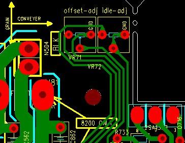
47 FR Offset Adj FR Idle Adj CT Offset Adj CT Idle Adj 4 Check Position FL Idle Check Position SL Idle Check Position SBL Idle Check Position 47


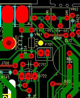
48 SR Idle Check Position SBR Idle Check Position FR Idle Check Position CT Idle Check Position 48

49 Service bulletin # HK January 2005 Service Bulletin Warranty labor rate: MINOR repair To: All Service Centers Model: AVR7300 Subject: A-BUS Output too High In the event you receive an AVR7300 with the complaint: There is distortion when using the A-BUS connection and a AB-1, perform the following modification: Synopsis: Change two resistors in the AVR7300. The actual symptom is that the AB-1 is not able to totally reduce the volume down even at the minimum position on the level control, so there is distortion, or low level audible bleed-through in Zone 2 1) Remove the top cover (18) Black & Plated Phillips screws at the sides and rear of the unit. 2) Remove the Tuner Module from the rear panel, two screws. It does not have to be disconnected. 3) Removal of the DSP PCB: there are seven screws on the rear panel; four plated screws that attach the PCB, six molex and ribbon connectors, and three connector PCB s must be pushed away from the DSP connectors. Remove the DSP board from the unit. 4) Removal of the Processor PCB: there are six screws on the rear panel; four standoff s that attach the PCB, eight molex connectors and three connector PCB s must be pushed away from the Processor connectors. Remove the Processor board. 5) Locate the two 1KΩ 1/16W SMD resistors R249 and R205 on the bottom of the Processor board; replace both with 2.7KΩ components, h/k part# RS3AD0272NA-0. 6) Replace all PCB s, connectors, standoffs and screws in reverse order. 7) Test the unit (with an AB-1). MODEL SERIAL NUMBER STATUS ACTION AVR7300 (120v) TF Distortion caused by too high Change R205, R249 from to output from A-BUS TF connection 1kΩ to 2.7kΩ AVR7300 (120v) TF and above Modified by Factory None Required AVR7300 (230v) TF and above Modified by Factory None Required 49
50 TECH TIPS Troubleshooting tips and solutions to common service problems For models: TIP# HKTT Rev3 AVR7000/7200/7300/8000 AVR100/200/300/500 AVR110/210/310/510 AVR120/220/320/520 AVR125/225/325/525 AVR130/230/330/430/630 AVR135/235/335/435/635 AVR10 DPR1001 DPR1005 DPR2005 HK3370/3470/3375/3475 HK3250 Subject: Backup Memory on AVR/DPR/HK series receivers In the event of the complaint: the receiver is losing its memory (any programmed system settings) when the unit is turned off, or after the unit is unplugged (briefly*) : Check and replace: Model Designator Location Description Part number AVR10 C Farad 5.5v capacitor # Front PCB D709 and 1N4148 diode # AVR7000 C730 Front PCB Farad 5.5v capacitor # or # J X AVR7200 C106 Front PCB Farad 5.5v capacitor # AVR7300 C657 DSP PCB Farad 5.5v capacitor # H01-CEZXA0479MN-5 AVR8000 C726 Front PCB Farad 5.5v capacitor # NR or # AVR100/200 C412 Front PCB Farad 5.5v capacitor # CEGT-B473J-0J0 AVR300 C906 Front PCB 0.1Farad 5.5v capacitor # J X or # P10791-ND AVR500 C906 Front PCB 0.1Farad 5.5v capacitor # J X or # P10791-ND AVR110/210/310/510 AVR120/220/320/520 C216 Front PCB Farad 5.5v capacitor # AVR125/225 C734,C885 Front PCB two 0.1F capacitors in parallel # BCESOHD104 AVR325/525 C106 Front PCB Farad 5.5v capacitor # AVR130/230/330 BAT1 Front PCB 3.6v Battery # HABGP40BVH3A3H AVR135/235/335 BAT1 Front PCB 3.6v Battery # HGP15BNH3A3H AVR430/630 C657 DSP PCB Farad 5.5v capacitor # CEZXA0479MN-5 AVR435/635 C657 DSP PCB Farad 5.5v capacitor # CEZXA0479MN-5 DPR1001 BC601 Main PCB 0.1Farad 5.5v capacitor # CEGT-B104J-0J0 DPR1005/2005 C437 Processor PCB Farad 5.5v capacitor # CEZXA0479MN-5 HK3370/3470 C301 Front PCB 0.1Farad 5.5v capacitor # CEGT-B104J-0J0 HK3375/3475 C301 Front PCB 0.1Farad 5.5v capacitor # CEGT-B104J-0J0 HK3250 C Farad 5.5v capacitor # Front PCB D709 and 1N4148 diode # * After approximately two weeks of being disconnected from AC supply, even a normally functioning receiver may lose any programmed settings and switch to default settings. 50
51 AVR7300 Electrical Parts List Ref Designator Part Number Description MAIN PCB Capacitors C CEHDC0108NN-3 CE 1MI0F +20% 6.3V 8X C ELITE C CEHEC01075E-8 CE 100U0F +20% 10.0V 5X11 85C P5MM C CEHEC02275E-9 CE 220UF +20% 10.0V D6.3XL11 P5MM 85C C CEHFC01075E-1 CE 100UF +20% 16.0V D6.3XL11 P5MM 85C C364 CEHFC04765E-3 CE47UF +20% 16.0V D5XL11 P5MM 85C C CEHIC01055E-6 CE 1UF +20% 50V D5XL11 P5MM 85C C CEHIC01065E-4 CE 10U0F +20% 50.0V 85C P5MM 5X11 C CEHIC02255E-7 CE 2U2F +20% 50V D5XL11 P5MM 85C C347 CEHIC0474NN-9 CE 470N0F +20% 50.0V 85C 5X11 ELITE C243 CEMFA02285E-5 CE 2200UF 16V M 12.5X20 P5MM C237 CEMFC03375E-A CE 330UF 16V M 8X11.5 P5MM 85C C H01-CEMFC0106AH-7 CAP ELEC 10UF 16V M 5X11 P5MM SHL C CEMFC0226NN-9 CAP ELEC 22UF 16V M ELITE C CEMGC0227NN-0 CAP ELEC 220UF 25V M 8X11.5 ELITE C338 CPIIC0223NN-4 CPF 22N0F +10% 50.0V C CPIKC0473NN-0 CPF 47N0F +10% 100.0V C342 CPIIC0682NN-5 CPF 6N8F +10% 50.0V C CCJIC0390NE-2 CC 39P0F +5% -5% 50.0V NP0 C261 H01-CEMIC0105AH-7 CE 1UF 50V M 5X11 SHL C358 H01-CEMIC0334AH-4 CAP ELEC 0.33UF M 5X11 SHL 50V SAMYOUNG C242 H01-CEMFA0109AH-6 CE MHA 10MI0F 16V M 16*35.5 SAMYOUN C H01-CEMHA0828AH-8 CAP ELEC 8200UF 35V M 22X45 AHS SAMYOUNG C244 H01-CEMIA0478AH-7 CAP ELEC 4700UF 50V M 22X45 DL SAMYOUNG C H01-CEMKA0228AH-0 CAP ELEC 2200UF 100V M 22X45 AHS SAMYOUNG C CZJII0101BE-2 CCCFMIC 100P0F +5% -5% 50.0V NP C340 CZJII0270BE-1 CCCFMIC 27P0F +5% -5% 50.0V NP C337 CZJII0330BE-9 CCCFMIC 33P0F +5% -5% 50.0V NP C CZKII0103BC-5 CAP CHIP 10N0F +10% -10% 50.0V X7R 0603 C92 CZKII0153BC-1 CAP CHIP 15N0F +10% -10% 50.0V X7R 0603 C91 CZKII0822BC-6 CAP CHIP 8N2F +10% -10% 50.0V X7R 0603 C CZZFI0104BF-8 CAP CHIP 100N0F +80% -20% 16.0V Y5V 0603 C262 CZDII0100BE-8 CAP CHIP 10PF 50V CH D NP P C CZJII0101BE-2 CCCFMIC 100P0F +5% -5% 50.0V NP C343 CZKII0103BC-5 CAP CHIP 10N0F +10% -10% 50.0V X7R 0603 C367 CZKII0223BC-6 CAP CHIP 22N0F +10% -10% 50.0V X7R 0603 C CZZFI0104BF-8 CAP CHIP 100N0F +80% -20% 16.0V Y5V 0603 C CFIOC0104NN-5 CPM 100N0F +10% 250.0V Semiconductors Q H01-TR2SA933ANW-2 TR-SLPLF 2SA933ASR P -3.0A -20V Q211 7 H01-TR2SC1740NW-9 TR-SLPLF 2SC1740S R N 150MI0A 50V Q6 H01-TRKTC3198NA-3 TR-SLPLF KTC3198BL N 150MI0A Q241 H01-TRKTD1302NA-0 TR-SLPLF KTD1302 B N 300MI0A 20V D H01-DRBU604F0NA-9 DIODE BRIDGE BU6-04F FRONTIER D202 H01-DRW204F00BA-A DIODE BRIDGE W2-04F FRONTIER IC214 H01-ICBA033T0I2-9 IC-REGPOSFXD BA033T NORMAL IC H01-ICKIA7805I2-7 IC-REGPOSFXD KIA7805API NORMAL TO-220IS IC207 H01-ICKIA7806I2-9 IC KIA7806AP VOLTQAGE REGULATOR TO-220AB IC H01-ICKIA7824I2-7 IC-REGPOSFXD KIA7824API TO-220IS NORMAL IC216 H01-ICKIA7905I2-5 IC-REGNEGFXD KIA7905PI NORMAL IC217 H01-ICLM07815BD-0 IC-REGPOSFXD KIA7815API NORMAL IC218 H01-ICLM07915BD-9 IC-REGNEGFXD KIA7915API NORMAL TO-220AB IC H01-ICPC17T10B1-2 IC PHOTOCOUPLER PC-17T1 DIP4 KODENSHI D H01-DS0KDS160NB-4 D-SLP KDS V 100MI0A 51
52 Ref Designator Part Number Description MAIN PCB D H01-DS1S50094NB-A D-SLP 1SS V 225MI0A Q H01-TRDTA114YNI-9 TR-SSD DTA114YKA P 10K0 OHM 47K0 OHM Q H01-TRDTC114YNI-5 TR-SSD DTC114YKA N 10K0 OHM 47K0 OHM Q5 H01-TR2SA1145NA-2 TR-SLPLF 2SA1145Y TO-92MOD P -50MI0A -150V IC208 H01-ICBU4094BD3-2 IC CMOS BU4094BF SOP16 IC209 H01-ICLC74763I4-1 IC OSD LC74763M SOP30 IC H01-ICMM1510XDL-7 IC-VIDEO SW MM1510XNRE SOT-26A IC H01-ICMM1501XDL-A IC-VIDEO SW MM1501XNRE SOT-26B IC206 H01-ICMM1511XDL-8 IC-VIDEO SW MM1511XNRE SOT-26B Q212 H01-TRDTC114YNI-5 TR-SSD DTC114YKA N 10K0 OHM 47K0 OHM Q3 221 H01-TRKTA1504ND-7 TRANSISTOR PNP KTA1504Y(S)SOT-23 D8 9 H01-DR1N04004NA-1 D-SR 1N V 1.0A Resistors R18 RC3DI0220IN-3 RESISTOR CARBON FILM 22OHM 1/4W 5% R13 RC3DI022AIN-2 RCF 2R2 OHM +5% 250MI0W R H01-RM3GC047ACN-9 RESISTOR METAL OXIDE 4R7 +5% 2.0W R H01-RM3HA056ADN-A RESISTOR METAL OXIDE 5R6 3W 5% RW R19 H01-RP3NA0101NZ-3 POS 100R0 OHM 16.0V RED R RS3AD0101NA RMGCFMIC 100R0 OHM +5% 62MI5W R232 RS3AD0102NA-3 RMGCFMIC 1K0 OHM +5% 62MI5W R RS3AD0103NA-1 RMGCFMIC 10K0 OHM +5% 62MI5W R15 17 RS3AD0104NA-A RMGCFMIC 100K0 OHM +5% 62MI5W R RS3AD0105NA-8 RES CHIP 1M 1/16W +-5% 0603 R RS3AD0121NA-A RMGCFMIC 120R0 OHM +5% 62MI5W R RS3AD0562NA-2 RMGCFMIC 5K6 OHM +5% 62MI5W R RS3AD0392NA-1 RMGCFMIC 3K9 OHM +5% 62MI5W R RS3AD0471NA-5 RMGCFMIC 470R0 OHM +5% 62MI5W R266 RS3AD0473NA-1 RMGCFMIC 47K0 OHM +5% 62MI5W R16 RS3AD0272NA-0 RMGCFMIC 2K7 OHM +5% 62MI5W R RS1AD0750NA-6 RES CHIP 75OHM 1% 1/16W 0603 R212 RS3AD0822NA-2 RMGCFMIC 8K2 OHM +5% 62MI5W R RS3AD0102NA-3 RMGCFMIC 1K0 OHM +5% 62MI5W R RS3AD0103NA-1 RMGCFMIC 10K0 OHM +5% 62MI5W R8 RS3AD0104NA-A RMGCFMIC 100K0 OHM +5% 62MI5W R234 RS3AD0121NA-A RMGCFMIC 120R0 OHM +5% 62MI5W R231 RS3AD0123NA-6 RMGCFMIC 12K0 OHM +5% 62MI5W R241 RS3AD0124NA-4 RMGCFMIC 120K0 OHM +5% 62MI5W R237 RS3AD0152NA-A RMGCFMIC 1K5 OHM +5% 62MI5W R239 RS3AD0154NA-6 RMGCFMIC 150K0 OHM +5% 62MI5W R3 RS3AD0000NA-0 RMGCFMIC 0 OHM +0% 62MI5W R304 RS3AD0222NA-4 RMGCFMIC 2K2 OHM +5% 62MI5W R6 RS3AD0223NA-2 RMGCFMIC 22K0 OHM +5% 62MI5W R240 RS3AD0224NA-0 RMGCFMIC 220K0 OHM +5% 62MI5W R303 RS3AD0333NA-6 RMGCFMIC 33K0 OHM +5% 62MI5W R7 RS3AD0392NA-1 RMGCFMIC 3K9 OHM +5% 62MI5W R4 RS1AD0471NA-A RESISTOR CHIP 470OHM 1/16W 1% 0603 R5 RS1AD4990NA-A RES CHIP 499OHM 1/16W 1% 0603 R238 RS3AD0513NA-4 RMGCFMIC 51K0 OHM +5% 62MI5W R236 RS3AD0682NA-3 RMGCFMIC 6K8 OHM +5% 62MI5W R302 RS3AD0750NA-1 RMGCFMIC 75R0 OHM +5% 62MI5W R1 RS3AD0820NA-6 RMGCFMIC 82R0 OHM +5% 62MI5W Miscellaneous L212 H01-FY N8-5 FILTER MPX JA203 SOMOD7400NN-6 JACK MODULAR JA202 H01-SOR12BJ12NN-3 JACK RCA 12P BJ120154JN JA201 H01-SORA11Y00NN-5 JACK RCA+S VIDEO C DN JA205 H01-SORA40RSANN-6 JACK RCA 4P JB040131ZN GN BN PP TA JA206 H01-SORA40RSCNN-A JACK RCA 4P JB040131QN WH BU RD GY L H01-LAINB0470CR-2 LF 47U0H +10% 5.8 OHM 500MI0A 52
53 Ref Designator Part Number Description MAIN PCB L213 H01-LAINB056ACR-0 LF 5U60H +10% 5.8 OHM 500MI0A N H01-WG04SD WIRE ASS'Y 2.5MM 4P 230MM UL1007#22 RED N211 H01-WG15SB WIRE ASS'Y 2.0MM 15P 280MM UL1007#26 RED P212 H01-WH20SC PIN HEADER 2.54MM 20P TPH P P211 H01-WH30SC00000-A PIN HEADER 2.54MM 30P TPH P N3 H01-WN02SB CONN 2.0MM 2 MA ST NAT GT201-2P-TS N4 H01-WN03SB CONN 2.0MM 3 MA ST NAT GT201-3P-TS P H01-WN06SD100WH-8 CONN WAFER 2.5MM 6P A WHT R H01-RM3FC010ABN-8 RESISTOR METAL OXIDE 1 OHM 1W 5% P205 H01-WN14SB100WH-1 CONN WAFER 2.0MM 14P WHT P H01-WN19SB CONN 2.0MM 19 MA ST NAT MOLEX JA204 H01-ZVD05FAN100-8 DC FAN TFD-4510L12B 45X45X10MM Y201 H01-OSXBE14M3AU-7 CRYSTAL MHz WOOIN Y202 H01-OSXBE17M7AU-9 CRYSTAL MHz WOOIN RY H01-RLL A-A RELAY D3009( ) G201 H01-ZNMSA4004SN-4 TERMLUG GND W350 H01-WG01S WIRE ASS'Y UL1007#16 STR 110MM 1P BLK TERMINAL F H01-FURN FUSE T 2A 250V 7.6X8.6 SS-5 SAVE FUSETECH Processor PCB Capacitors C CEHDC0108NN-3 CE 1MI0F +20% 6.3V 8X C ELITE C CEHFC04765E-3 CE47UF +20% 16.0V D5XL11 P5MM 85C C CEHIC04755E-6 CE 4U7F +20% 50.0V 85C P5MM C H01-CEMFC0106AH-7 CAP ELEC 10UF 16V M 5X11 P5MM SHL C CZJII0101BE-2 CCCFMIC 100P0F +5% -5% 50.0V NP C CZJII0330BE-9 CCCFMIC 33P0F +5% -5% 50.0V NP C CZKII0821BC-8 CAP CHIP 820P0F +10% -10% 50.0V X7R 0603 C CZKII0222BC-8 CAP CHIP 2N2F +10% -10% 50.0V X7R 0603 C CZZFI0104BF-8 CAP CHIP 100N0F +80% -20% 16.0V Y5V 0603 C CZJII0150BE-0 CCCFMIC 15P0F +5% -5% 50.0V NP C CZJII0330BE-9 CCCFMIC 33P0F +5% -5% 50.0V NP C CZKII0103BC-5 CAP CHIP 10N0F +10% -10% 50.0V X7R 0603 C CZKII0222BC-8 CAP CHIP 2N2F +10% -10% 50.0V X7R 0603 C CZKII0682BC-7 CAP CHIP 6N8F 50V X7R K 0603 Semiconductors D6 H01-DZMTZJ5B6NB-5 DIODE ZENER MTZ J5.6B 5.6V 500MW DO-34 Q H01-TRKTD1302NA-0 TR-SLPLF KTD1302 B N 300MI0A 20V Q2 5 H01-TRMPSA06NNA-4 TR-SLPLF MPSA06 N 500MI0A TO-92 Q4 6 H01-TRMPSA56YNA-5 TR-SLPLF MPSA56 Y P -500MI0A -300V D H01-DS1S50094NB-A D-SLP 1SS V 225MI0A IC29 30 H01-ICLM02068D2-A IC-OPERAMP NJM2068M DUAL SOP8 53
54 Ref Designator Part Number Description Processor PCB IC10 H01-ICTC9273NDA-0 IC-SWITCH TC9273F-004 SOP28 ANALOG SWITCH Q54 H01-TRDTC114YNI-5 TR-SSD DTC114YKA N 10K0 OHM 47K0 OHM Q H01-TRKTD1304ND-5 TR-SLPSWA KTD1304 N 20V 300MI0A SOT-23 D Q47 H01-DSUDZ09V1NB-7 D-ZENER UDZS 9.1B 9.1V 200MI0W IC5 14 H01-ICKIC9162DA-5 IC-SWITCH KIC9162AF SOP28 ANALOG SWITCH IC3 H01-ICKIC9163DA-7 IC-SWITCH KIC9163AF SOP28 ANALOG SWITCH IC2 18 H01-ICKIC9459D5-8 IC-LOWFREQ KIC9459F SOP24 TONE/VOL/BAL/MUTE IC H01-ICLM02068D2-A IC-OPERAMP NJM2068M DUAL SOP8 IC19 H01-ICLMO9482DA-5 IC-LOWFREQ KIC9482F/TC9482F SOP28 TONE/VOL/BAL/MUTE IC6 H01-ICTC9273NDA-0 IC-SWITCH TC9273F-004 SOP28 ANALOG SWITCH IC28 H01-ICTC9481FDA-0 IC-LOWFREQ TC9481F SOP28 TONE Q H01-TRDTA114YNI-9 52 TR-SSD DTA114YKA P 10K0 OHM 47K0 OHM Q22 H01-TRDTC114YNI-5 TR-SSD DTC114YKA N 10K0 OHM 47K0 OHM Q H01-TRKTD1304ND-5 TR-SLPSWA KTD1304 N 20V 300MI0A SOT-23 Resistors R RS3AD0000NA-0 RMGCFMIC 0 OHM +0% 62MI5W R RS3AD0101NA-5 RMGCFMIC 100R0 OHM +5% 62MI5W R RS3AD0102NA RMGCFMIC 1K0 OHM +5% 62MI5W R RS3AD0104NA-A RMGCFMIC 100K0 OHM +5% 62MI5W R RS3AD0123NA-6 RMGCFMIC 12K0 OHM +5% 62MI5W R RS3AD0152NA-A RMGCFMIC 1K5 OHM +5% 62MI5W R RS3AD0202NA-A RMGCFMIC 2K0 OHM +5% 62MI5W R RS3AD0222NA-4 RMGCFMIC 2K2 OHM +5% 62MI5W R RS3AD0333NA-6 RMGCFMIC 33K0 OHM +5% 62MI5W R RS3AD0362NA-A RMGCFMIC 3K6 OHM +5% 62MI5W R RS3AD0432NA-4 RMGCFMIC 4K3 OHM +5% 62MI5W R RS3AD0470NA-7 RMGCFMIC 47R0 OHM +5% 62MI5W R RS3AD0471NA-5 RMGCFMIC 470R0 OHM +5% 62MI5W R128 RS3AD0472NA-3 RMGCFMIC 4K7 OHM +5% 62MI5W R RS3AD0512NA-6 RMGCFMIC 5K1 OHM +5% 62MI5W R RS3AD0821NA-4 RMGCFMIC 820R0 OHM +5% 62MI5W R248 RS3AD0912NA-1 RMGCFMIC 9K1 OHM +5% 62MI5W R201 RS3AD0220NA-8 RMGCFMIC 22R0 OHM +5% 62MI5W R RS3AD0562NA-2 RMGCFMIC 5K6 OHM +5% 62MI5W R RS3AD0242NA-9 RMGCFMIC 2K4 OHM +5% 62MI5W 54
55 Ref Designator Part Number Description Processor PCB R RS3AD0100NA-7 RMGCFMIC 10R0 OHM +5% 62MI5W R RS3AD0101NA-5 RMGCFMIC 100R0 OHM +5% 62MI5W R RS3AD0102NA-3 RMGCFMIC 1K0 OHM +5% 62MI5W R90 RS3AD0104NA-A RMGCFMIC 100K0 OHM +5% 62MI5W R RS3AD0123NA-6 RMGCFMIC 12K0 OHM +5% 62MI5W R RS3AD0183NA-A RMGCFMIC 18K0 OHM +5% 62MI5W R RS3AD0222NA-4 RMGCFMIC 2K2 OHM +5% 62MI5W R RS3AD0332NA-8 RMGCFMIC 3K3 OHM +5% 62MI5W R RS3AD0333NA-6 RMGCFMIC 33K0 OHM +5% 62MI5W R182 RS3AD0471NA-5 RMGCFMIC 470R0 OHM +5% 62MI5W R RS3AD0472NA-3 RMGCFMIC 4K7 OHM +5% 62MI5W R RS3AD0474NA-A RMGCFMIC 470K0 OHM +5% 62MI5W R197 RS3AD0220NA-8 RMGCFMIC 22R0 OHM +5% 62MI5W R RS3AD0153NA-8 RES CHIP,15K 1/16W,+-5%,0603. R318 RC3DI0100IN-2 RCF 10R0 OHM +5% 250MI0W R RC3DI0153IN-3 RCF 15K0 OHM +5% 250MI0W Miscellaneous SK1 H01-RLL A-5 RELAYSGNL 12.0V 960.0OHM 3.0A NJ H01-SORA40GNDNN-7 JACK RCA 4P JB040131PN WWRR NJ55 H01-SORA64105NN-5 JACK RCA 6P JB060132PN P516 H01-WG04SB WIRE ASS'Y DL 2.0MM 4P 110MM UL1007 #26 RED P508 H01-WN03SD100WH-6 CONN WAFER 2.5MM 3P A WHT P2 517 H01-WN04AB100WH-8 CONN WAFER 2.0MM 4P WHT P513 H01-WN04SB CONN 2.0MM 4 MA ST NAT GT201-4P-TS P H01-WN04SD100WH-3 CONN WAFER 2.5MM 4P A WHT P H01-WN05SD100WH-0 CONN WAFER 2.5MM 5P A WHT P505 H01-WN06SD100WH-8 CONN WAFER 2.5MM 6P A WHT P510 H01-WN07SD CNT PLUG ST 2.5mm 7P A P503 H01-WN14AB100WH-4 CONN WAFER 2.0MM 14P WHT P504 H01-WN15SI CONN FFC 1.25MM 15P SCB VER P509 H01-WN19AB CONN 2.0MM 19 MA R NAT SOCKET MOLEX P501 H01-WN19SB CONN 2.0MM 19 MA ST NAT MOLEX P1 H01-WSE261705EN-0 WIRE ASS'Y 15P 170MM UL2547/1533#26 RED SHIELD DSP PCB Capacitors C CEHDC0108NN-3 CE 1MI0F +20% 6.3V 8X C ELITE C5 CEHEC01075E-8 CE 100U0F +20% 10.0V 5X11 85C P5MM C CEHFC01062S-0 CE 10UF +20% 16V D4XL7 P2.5MM 2000hours 85C C CEHFC01072S-9 CE 100UF +20% 16V D6.3XL7 P2.5MM 2000hours 85C C CEHFC04762S-0 CE 47UF +20% 16V D5XL7 P2.5MM 2000hours 85C C CEHIC01055E-6 CE 1UF +20% 50V D5XL11 P5MM 85C C806 CEHIC02255E-7 CE 2U2F +20% 50V D5XL11 P5MM 85C C619 CEHIC01042S-5 CE 100NF +20% 50V SSE TYPE D4XL7 P2.5MM 85C C H01-CEMFC0108AH-0 CAP ELEC 1000UF 16V M 10X16 SHL SAMYOUNG C725 H01-CEMIC0475AH-8 CE 4.7UF 50V M 5X11 SHL SAMYOUNG C30 CEHEC0477MN-A CE 470U0F +20% 10.0V 6.3X11 85C ELITE C657 H01-CEZXA0479MN-5 CM 47MI0F +80% -20% 5.5V 70C SCDA5R5473V 55
56 Ref Designator Part Number Description DSP PCB C CZJII0101BE-2 CCCFMIC 100P0F +5% -5% 50.0V NP C CZJII0220BE-5 CCCFMIC 22P0F +5% -5% 50.0V NP C890 CZJII0471BE-2 CCCFMIC 470P0F +5% -5% 50.0V NP C CZJII0561CE-0 CCCFMIN 560P0F +5% -5% 50.0V NP C805 CZJII0680BE-4 CAPACITOR CERAMIC CHIP 68PF 50V CH J NPO 0603 C CZKII0102BC-7 CAP CHIP 1N0F +10% -10% 50.0V X7R 0603 C CZKII0103BC-5 CAP CHIP 10N0F +10% -10% 50.0V X7R 0603 C804 CZKII0122BC-1 CAP CHIP 1N2F +10% -10% 50.0V X7R 0603 C6 8 CZJII0331BE-7 CCCFMIC 330P0F +5% -5% 50.0V NP C CZKII0272BC-4 CAP CHIP 2N7F +10% -10% 50.0V X7R C CZZFI0104BF-8 CAP CHIP 100N0F +80% -20% 16.0V Y5V 0603 C CZJII0101BE-2 CCCFMIC 100P0F +5% -5% 50.0V NP C743 CZJII0220BE-5 CCCFMIC 22P0F +5% -5% 50.0V NP C CZJII0561CE-0 CCCFMIN 560P0F +5% -5% 50.0V NP C CZKII0102BC-7 CAP CHIP 1N0F +10% -10% 50.0V X7R 0603 C CZKII0103BC-5 CAP CHIP 10N0F +10% -10% 50.0V X7R 0603 C CZZFI0104BF-8 CAP CHIP 100N0F +80% -20% 16.0V Y5V 0603 C7 CZJII0390BE-2 CAP CHIP 39PF 50V CH J NPO 0603 C720 CZKGI0183BC-6 CAP CHIP 18NF 25V +/-10% 0603 X7R C9 CZKII0221BA-3 CAP CHIP 220PF 50V K SL 0603 Semiconductors Q611 H01-TRMPSA06NNA-4 TR-SLPLF MPSA06 N 500MI0A TO-92 IC21 H01-ICKA78R08I2-4 IC-KA78R08API TO-220IS-4PIN D H01-DS1S50094NB-A D-SLP 1SS V 225MI0A IC804 H01-IC49L8192I5-A IC-FLASH MEMORY ROM AT49LV8192A 70ns IC H01-IC74V244MG5-3 IC-LOGIC 74VHCT244A INVERTER CMOS IC5 H01-ICBU4053BB4-7 IC BU4053BCF SOP16 ANALOG MPX/DEMPX IC16 H01-ICBU4094BD3-2 IC CMOS BU4094BF SOP16 IC13 H01-ICCS42528EC-0 IC-CODEC CS42528CQ IC26 H01-ICCS4391AD8-5 IC CONV CS4391A-KZ SOP20 IC11 H01-ICCS49400ED-3 IC-DSP CS CQ LQFP144 IC H01-ICCS5361KG4-0 IC-CONV CS5361-KZ A/D TSSOP24 IC12 H01-ICD703033E1-5 IC-MICOM FLASH NEC UPD70F3033BGF 0228KK001 JAPAN QFP100 IC14 H01-ICK4S1616M6-9 IC-SDRAM K4S161622E-TC70 OR TC80 IC H01-ICLM02068D2-A IC-OPERAMP NJM2068M DUAL SOP8 IC22 H01-ICM24C04WD2-1 IC-EEPROM M24C04WMN6T IC19 20 H01-ICM74H04MD4-2 IC-LOGIC M74HCU04M1R INVERTER HCT 56
57 Ref Designator Part Number Description DSP PCB IC24 H01-ICMM1662HI3-2 IC MM1662H LOW DROP VOLTAGE REGULATOR SOP-8 IC23 H01-ICNJU6324D2-3 IC-SPECFUNC NJU6324M SOP8 CMOS CRYSTAL Q H01-TRDTC114YNI-5 TR-SSD DTC114YKA N 10K0 OHM 47K0 OHM D601 H01-DS1S50094NB-A D-SLP 1SS V 225MI0A Q H01-TRDTA114YNI-9 TR-SSD DTA114YKA P 10K0 OHM 47K0 OHM Q H01-TRKTD1304ND-5 TR-SLPSWA KTD1304 N 20V 300MI0A SOT-23 Resistors R735 RS3AD0391NA-3 RMGCFMIC 390R0 OHM +5% 62MI5W R619 RC3DI010AIN-1 RCF 1R0 OHM +5% 250MI0W R22 RC3DI0560IN-1 RCF 56 OHM +5% 250MI0W R23 RC3DI022AIN-2 RCF 2R2 OHM +5% 250MI0W R RS3AD0101NA-5 RMGCFMIC 100R0 OHM +5% 62MI5W R RS3AD0102NA-3 RMGCFMIC 1K0 OHM +5% 62MI5W R RS3AD0103NA-1 RMGCFMIC 10K0 OHM +5% 62MI5W R RS3AD0104NA-A RMGCFMIC 100K0 OHM +5% 62MI5W R R RS3AD0122NA-8 RS3AD0151NA-1 RMGCFMIC 1K2 OHM +5% 62MI5W RMGCFMIC 150R0 OHM +5% 62MI5W R799 RS3AD0200NA-3 RES,CHIP 20 OHM 1/16W +/-5% 0603 R RS3AD0203NA-8 RMGCFMIC 20K0 OHM +5% 62MI5W R24 RS3AD0221NA-6 RMGCFMIC 220R0 OHM +5% 62MI5W R870 RS3AD0302NA-6 RMGCFMIC 3K0 OHM +5% 62MI5W R RS3AD0332NA-8 RMGCFMIC 3K3 OHM +5% 62MI5W R RS3AD0432NA-4 RMGCFMIC 4K3 OHM +5% 62MI5W R RS3AD0472NA-3 RMGCFMIC 4K7 OHM +5% 62MI5W R RS3AD0473NA-1 RMGCFMIC 47K0 OHM +5% 62MI5W R RS3AD0561NA-4 RMGCFMIC 560R0 OHM +5% 62MI5W R RS3AD0562NA-2 RMGCFMIC 5K6 OHM +5% 62MI5W 447 R113 RS3AD0682NA-3 RMGCFMIC 6K8 OHM +5% 62MI5W R RS3AD0750NA-1 RMGCFMIC 75R0 OHM +5% 62MI5W R RS3AD0000NA-0 RMGCFMIC 0 OHM +0% 62MI5W R RS3AD0000NA-0 RMGCFMIC 0 OHM +0% 62MI5W R RS3AD0100NA-7 RMGCFMIC 10R0 OHM +5% 62MI5W R RS3AD0101NA-5 RMGCFMIC 100R0 OHM +5% 62MI5W R RS3AD0102NA-3 RMGCFMIC 1K0 OHM +5% 62MI5W R RS3AD0103NA-1 RMGCFMIC 10K0 OHM +5% 62MI5W R RS3AD0104NA-A RMGCFMIC 100K0 OHM +5% 62MI5W R RS3AD0122NA-8 RMGCFMIC 1K2 OHM +5% 62MI5W R RS3AD0151NA-1 RMGCFMIC 150R0 OHM +5% 62MI5W R RS3AD0203NA-8 RMGCFMIC 20K0 OHM +5% 62MI5W 57
58 Ref Designator Part Number Description DSP PCB R RS3AD0222NA-4 RMGCFMIC 2K2 OHM +5% 62MI5W R2 875 RS3AD0332NA-8 RMGCFMIC 3K3 OHM +5% 62MI5W R RS3AD0471NA-5 RMGCFMIC 470R0 OHM +5% 62MI5W R RS3AD0472NA-3 RMGCFMIC 4K7 OHM +5% 62MI5W R RS3AD0473NA-1 RMGCFMIC 47K0 OHM +5% 62MI5W R RS3AD0511NA-8 RMGCFMIC 510R0 OHM +5% 62MI5W R RS3AD0561NA-4 RMGCFMIC 560R0 OHM +5% 62MI5W R723 RS3AD0750NA-1 RMGCFMIC 75R0 OHM +5% 62MI5W R625 RS3AD0822NA-2 RMGCFMIC 8K2 OHM +5% 62MI5W RX RS3AY0103NA-7 RCA 10K0 OHM +5% 62M15W 4 RX22 24 RS3AY0332NA-3 RCA 3K3 OHM +5% 62M15W 4 RX RS3AY0470NA-2 RCA 47R0 OHM +5% 62M15W 4 R RS3AD0221NA-6 RMGCFMIC 220R0 OHM +5% 62MI5W Miscellaneous L H01-LAINB0470CR-2 LF 47U0H +10% 5.8 OHM 500MI0A L600 H01-LAINB047ACR-3 LF 4U7H +10% 1.7 OHM 190.0A L R879 H01-FB NN-4 FBEAD SURFACE MT 300OHM FCM2012V-301T07 L H01-FB NN FBEAD SURFACE MT 300OHM FCM2012V-301T07 L700 H01-FB2K52012NN-5 FBEAD SURFACE MT 2500OHM FCM2012H-252T02 TF11 12 H01-LF11030A2NA-4 TFPULSE TRANSFORMER 110UH FP-110 FERRIT MAGNET Y800 H01-OSCEM24M5RU-A VCXO 24M576 HZ +50 PPM -50 PPM 0 OHM 3.3V Y600 H01-OSCNI20MOCU-6 CSTLS20MOX51-B0 NJ12 H01-SORA40RSANN-6 JACK RCA 4P JB040131ZN GN BN PP TA NJ11 H01-SORA40RSCNN-A JACK RCA 4P JB040131QN WH BU RD GY NJ H01-SOTOR179LBA-0 D-LEM TORX-179L NJ17 H01-SOTOT179LBA-7 D-LEM TOTX-179L N105 H01-WG09SB83000-A WIRE ASS'Y 2.0MM 9P 300MM UL1007#26 WHT P104 H01-WN04AB100WH-8 CONN WAFER 2.0MM 4P WHT P117 H01-WN04SB CONN 2.0MM 4 MA ST NAT GT201-4P-TS P102 H01-WN06SB CONN 2.0MM 6 MA ST NAT GT201-6P-TS P101 H01-WN08SB CONN 2.0MM 8 MA ST NAT GT201-8P-TS P106 H01-WN15AI CONN FFC 1.25MM 15P SCB ANG P1 110 H01-WN15SB CONN 2.0MM 15 MA ST NAT GT201-15P-TS P H01-WN19AB CONN 2.0MM 19 MA R NAT SOCKET MOLEX P103 H01-WN23SI CONN FFC 1.25MM 23P SCB VER NJ13 H01-SOJB04013HN-5 JACK RCA 4P OR,OR, OR, OR JB040131HN 3 CHANNEL AMP Capacitors C CCJIC0120NN-2 CAP CERAMIC 12PF 50V J CH TAP C CCKIC0101NC-9 CAP CERAMIC 100PF 50V K X7R TAP C CCKIC0221NC-A CAP CERAMIC 220PF 50V K X7R TAP C CCKIC0681NA-2 CC 680P0F +10% -10% 50.0V Y5P C CEHEC0477MN-A CE 470U0F +20% 10.0V 6.3X11 85C ELITE C CEHGC0107MN-7 CE 100U0F +20% 25.0V 6.3X11P2.5MM 85C C902 CEHIC01055E-6 CE 1UF +20% 50V D5XL11 P5MM 85C C CEHIC04765E-4 CE 47U0F +20% 50.0V 85C P5MM C917 CEMIC02265E-9 CAP, ELECT, 22uF, 50V +/-20% C CPIKC0103NN-0 CAP POLY NON METAL 10NF 100V 10% C CPIKC0472NN-2 CAP POLY NON METAL 4N7F 100V 10% C CPIKC0473NN-0 CPF 47N0F +10% 100.0V C CPJJC0683NN-A CAP POLY NON METAL 68NF 63V J TAP C H01-CEMFC01062H-6 CAP ELEC 10UF 16V M 5X11 SHL P2.5MM C CFIOC0104NN-5 CPM 100N0F +10% 250.0V 58
59 Ref Designator Part Number Description 3 CHANNEL AMP C Semiconductors H01-CEMKA0127AH-0 CAP ELEC 120UF 100V M 12X16 AHS D907 H01-DZ1N05231NB-1 D-ZENER 1N5231B 5.1V 500MI0W D H01-DR1N04004NA-1 D-SR 1N V 1.0A D H01-DG1N04148NB-4 D-SLP 1N V 150E-3A D H01-DR01SS244NA-2 DIODE 1SS V Q H01-TR2SC1740NW-9 TR-SLPLF 2SC1740S R N 150MI0A 50V Q901 H01-TRKTA1024NA-7 TR-SLPLF KTA1024 Y P 50MI0A -150V Q925 H01-TRKTA1266NA-0 TR-SLPLF KTA1266 Y P 150MI0A Q H01-TRKTA1268NA-4 TR-SHPLF KTA1268BL P 100MI0A 120V Q H01-TRKTC3198NA-3 TR-SLPLF KTC3198BL N 150MI0A Q H01-TRKTC3200NA-9 TR-SHPLF KTC3200BL N 100MI0A 120V Q902 H01-TRDTC114YNW-6 TR-SLPLF DTC114YSA N 100MI0A Q H01-TR2SA1360BC-6 TRANSISTOR PNP 2SA1360-Y 50MI0A -150V Q H01-TR2SA1370BC-7 TRANSISTOR PNP 2SA1370-E 100MI0A Q H01-TR2SA1859BC-2 TR-SHPLF 2SA1859A P -2.0A Q H01-TR2SA1943RP-A TRANSISTOR PNP 2SA1943-O TO-220 Q H01-TR2SC3423BC-0 TRANSISTOR NPN 2SC3423-Y 50MI0A 150V Q H01-TR2SC4137BE-0 TR-SHPLF 2SC4137 N 100MI0A 20V Q H01-TR2SC4883BC-8 TR-SHPLF 2SC4883A N 2.0A Q H01-TR2SC5200RP-6 TRANSISTOR NPN 2SC5200-O TO-220 Resistors R H01-RM3FC022ANN-0 RESISTOR METAL OXIDE 2R2 OHM 1W 5% R RC3DI0101IN-0 RCF 100R0 OHM +5% 250MI0W R RC3DI0102IN-9 RCF 1K0 OHM +5% 250MI0W R963 RC3DI0103IN-7 RCF 10K0 OHM +5% 250MI0W R RC3DI0104IN-5 RCF 100K0 OHM +5% 250MI0W R RC3DI0122IN-3 RCF 1K2 OHM +5% 250MI0W R RC3DI0151IN-7 RCF 150 OHM 5% 1/4W R RC3DI0152IN-5 RCF 1K5 OHM +5% 250MI0W R RC3DI0153IN-3 RCF 15K0 OHM +5% 250MI0W R901 RC3DI0181IN-9 RCF 180 OHM +5% 250MI0W R RC3DI0182IN-7 RCF 1K8 OHM 5% 1/4W R RC3DI0220IN-3 RESISTOR CARBON FILM 22OHM 1/4W 5% R RC3DI0221IN-1 RCF 220R0 OHM +5% 250MI0W R RC3DI0222IN-A RCF 2K2 OHM +5% 250MI0W R969 RC3DI0332IN-3 RCF 3K3 OHM 5% 1/4W R RC3DI0333IN-1 RCF 33K0 OHM +5% 250MI0W R RC3DI0471IN-0 RCF 470R0 OHM +5% 250MI0W R RC3DI0473IN-7 RCF 47K OHM +5% 250MI0W R RC3DI0560IN-1 RCF 56 OHM +5% 250MI0W R RC3DI0561IN-A RCF 560R0 OHM +5% 250MI0W R964 RC3DI0562IN-8 RCF 5K6 OHM +5% 250MI0W R RC3DI0621IN-7 RCF 620 OHM +5% 250MI0W R RC3DI0682IN-9 RCF 6K8 OHM +5% 250MI0W R962 RC3DI0683IN-7 RCF 68K OHM 5% 1/4W R H01-RC1QC2431IN-6 RES CARBON FILM 2K43 OHM 1/5W 1% R RM1DI0333IN-4 RMF 33K0 OHM +1% 250MI0W R H01-RM3EG0100LN-A RMF 10R0 OHM +5% 500MI0W R H01-RM3EG0101LN-1 RESISTOR METAL OXIDE 100 OHM 1/2W 5% 59
60 Ref Designator Part Number Description 3 CHANNEL AMP R H01-RM3EG0150LN-4 RESISTOR METAL OXIDE 15 OHM 1/2W 5% R H01-RM3EG022ALN-0 RESISTOR METAL OXIDE 2R2 OHM 1/2W 5% R H01-RM3EG0820LN-9 RESISTOR METAL OXIDE 82 OHM 1/2W 5% R H01-RC1QC2671IN-6 RES CARBON FILM 2K67 OHM 1/5W 1% R H01-RM3FC0560BN-5 RESISTOR METAL OXIDE 56 OHM 1W 5% R H01-RI3IC022BEN-8 RW 220MI0 OHM +5% 5.0W 100PPM/'C -100PPM/'C Miscellaneous B H01-FB44HM LF BEADS HM 100MHZ FB-30 HC-3550 G H01-ZNMSA4004SN-4 TERMLUG GND N309 H01-WG03SE WIRE ASS'Y 3.96MM 3P 160/300/380MM UL1007#16 STR BLU N310 H01-WG03SE WIRE ASS'Y 3.96MM 3P 140/260/370MM UL1007#16 STR RED L H01-LCNNNA050NA-1 LFA 1MM 10MM 5 LEFT 0.0MM NONE SK H01-RL1K124V05A-2 RELAY SGNL OMI-SS-224L 1K1 OHM 24V 5A R H01-RM3GC0100CN-7 RESISTOR METAL OXIDE 10R0 OHM +5% 2.0W RV H01-RT7EA0201NB-6 PR 200R0 OHM +20% 500MI0W RV H01-RT7EA0500NB-9 PR 50R0 OHM +20% 500MI0W NJ33 H01-SOSP20117NN-6 JACK SPEAKER 2P B N BK/WH NJ32 H01-SOSP20118NN-8 JACK SPEAKER 2P B N BK/BU NJ31 H01-SOSP20119NN-A JACK SPEAKER 2P B N BK/BRN N312 H01-WG02SE WIRE ASS'Y 3.96MM 2P 170/250MM UL1007#18 BLU P702 H01-WG02SE852BK-9 WIRE ASS'Y 3.96MM 2P 520MM UL1007#16 BLK N704 H01-WG02SE852RD-7 WIRE ASS'Y 3.96MM 2P 520MM UL1007#16 RED N311 H01-WG03SE WIRE ASS'Y 3.96MM 3P 200MM UL1007#16 RED N306 H01-WG03SE WIRE ASS'Y 3.96MM 3P 230/200/230MM UL1007#18 WHT P H01-WN02SD CONN 2.5MM 2 MA ST NAT 0 0 P202 H01-WN04SD100WH-3 CONN WAFER 2.5MM 4P A WHT P H01-WN07AB100WH-A CONN WAFER 2.0MM 7P WHT P H01-WN07SB100WH-7 CONN WAFER 2.0MM 7P WHT N303 H01-WS FN-0 WIRE ASS'Y 2.5MM 4P 240MM UL1007/2547#24/26 SHIELD N302 H01-WS FN-7 WIRE ASS'Y 2.5MM 5P 150MM UL1007/2547 #24/26 SHIELD N301 H01-WS FN-1 WIRE ASS'Y 2.5MM 7P 150MM UL1007/2547 #24/26 SHIELD 4 CHANNEL AMP Capacitors C CCJIC0120NN-2 CAP CERAMIC 12PF 50V J CH TAP C CCKIC0101NC-9 CAP CERAMIC 100PF 50V K X7R TAP C CCKIC0221NC-A CAP CERAMIC 220PF 50V K X7R TAP C CCKIC0681NA-2 CC 680P0F +10% -10% 50.0V Y5P C CEHEC0477MN-A CE 470U0F +20% 10.0V 6.3X11 85C ELITE C CEHGC0107MN-7 CE 100U0F +20% 25.0V 6.3X11P2.5MM 85C C802 CEHIC01055E-6 CE 1UF +20% 50V D5XL11 P5MM 85C C CEHIC04765E-4 CE 47U0F +20% 50.0V 85C P5MM C CPIKC0103NN-0 CAP POLY NON METAL 10NF 100V 10% C CPIKC0472NN-2 CAP POLY NON METAL 4N7F 100V 10% C CPIKC0473NN-0 CPF 47N0F +10% 100.0V C CPJJC0683NN-A CAP POLY NON METAL 68NF 63V J TAP C H01-CEMFC01062H-6 CAP ELEC 10UF 16V M 5X11 SHL P2.5MM C CFIOC0104NN-5 CPM 100N0F +10% 250.0V C H01-CEMKA0127AH-0 CAP ELEC 120UF 100V M 12X16 AHS 60
61 Ref Designator Part Number Description 4 CHANNEL AMP Semiconductors D H01-DG1N04148NB-4 D-SLP 1N V 150E-3A D H01-DR1N04004NA-1 D-SR 1N V 1.0A Q801 H01-TRKTA1024NA-7 TR-SLPLF KTA1024 Y P 50MI0A -150V Q H01-TRKTA1268NA-4 TR-SHPLF KTA1268BL P 100MI0A 120V Q H01-TRKTC3198NA-3 TR-SLPLF KTC3198BL N 150MI0A Q H01-TRKTC3200NA-9 TR-SHPLF KTC3200BL N 100MI0A 120V 722 Q802 H01-TRDTC114YNW-6 TR-SLPLF DTC114YSA N 100MI0A Q H01-TR2SA1360BC-6 TRANSISTOR PNP 2SA1360-Y 50MI0A -150V Q H01-TR2SA1370BC-7 TRANSISTOR PNP 2SA1370-E 100MI0A Q H01-TR2SA1859BC-2 TR-SHPLF 2SA1859A P -2.0A Q H01-TR2SA1943RP-A TRANSISTOR PNP 2SA1943-O TO-220 Q H01-TR2SC3423BC-0 TRANSISTOR NPN 2SC3423-Y 50MI0A 150V Q H01-TR2SC4137BE-0 TR-SHPLF 2SC4137 N 100MI0A 20V Q H01-TR2SC4883BC-8 TR-SHPLF 2SC4883A N 2.0A Q H01-TR2SC5200RP-6 TRANSISTOR NPN 2SC5200-O TO-220 D H01-DR01SS244NA-2 DIODE 1SS V Resistors R RC3DI0101IN-0 RCF 100R0 OHM +5% 250MI0W R RC3DI0102IN-9 RCF 1K0 OHM +5% 250MI0W R RC3DI0122IN-3 RCF 1K2 OHM +5% 250MI0W R RC3DI0151IN-7 RCF 150 OHM 5% 1/4W R RC3DI0152IN-5 RCF 1K5 OHM +5% 250MI0W R RC3DI0153IN-3 RCF 15K0 OHM +5% 250MI0W R801 RC3DI0181IN-9 RCF 180 OHM +5% 250MI0W R RC3DI0220IN-3 RESISTOR CARBON FILM 22OHM 1/4W 5% R RC3DI0221IN-1 RCF 220R0 OHM +5% 250MI0W R RC3DI0222IN-A RCF 2K2 OHM +5% 250MI0W R RC3DI0333IN-1 RCF 33K0 OHM +5% 250MI0W R RC3DI0471IN-0 RCF 470R0 OHM +5% 250MI0W R RC3DI0473IN-7 RCF 47K OHM +5% 250MI0W R RC3DI0560IN-1 RCF 56 OHM +5% 250MI0W R RC3DI0561IN-A RCF 560R0 OHM +5% 250MI0W R RC3DI0621IN-7 RCF 620 OHM +5% 250MI0W R RC3DI0682IN-9 RCF 6K8 OHM +5% 250MI0W R H01-RC1QC2431IN-6 RES CARBON FILM 2K43 OHM 1/5W 1% R H01-RC1QC2671IN-6 RES CARBON FILM 2K67 OHM 1/5W 1% R RM1DI0333IN-4 RMF 33K0 OHM +1% 250MI0W B H01-FB44HM LF BEADS HM 100MHZ FB-30 HC-3550 R H01-RM3EG0100LN-A RMF 10R0 OHM +5% 500MI0W R H01-RM3EG0101LN-1 RESISTOR METAL OXIDE 100 OHM 1/2W 5% R H01-RM3EG0150LN-4 RESISTOR METAL OXIDE 15 OHM 1/2W 5% R H01-RM3EG022ALN-0 RESISTOR METAL OXIDE 2R2 OHM 1/2W 5% R H01-RM3EG0820LN-9 RESISTOR METAL OXIDE 82 OHM 1/2W 5% R H01-RM3FC022ANN-0 RESISTOR METAL OXIDE 2R2 OHM 1W 5% R H01-RM3FC0560BN-5 RESISTOR METAL OXIDE 56 OHM 1W 5% R H01-RM3GC0100CN-7 RESISTOR METAL OXIDE 10R0 OHM +5% 2.0W R H01-RI3IC022BEN-8 RW 220MI0 OHM +5% 5.0W 100PPM/'C -100PPM/'C 61
62 Ref Designator Part Number Description 4 CHANNEL AMP VR H01-RT7EA0201NB-6 PR 200R0 OHM +20% 500MI0W VR H01-RT7EA0500NB-9 PR 50R0 OHM +20% 500MI0W Miscellaneous G H01-ZNMSA4004SN-4 TERMLUG GND L H01-LCNNNA050NA-1 LFA 1MM 10MM 5 LEFT 0.0MM NONE SK H01-RL1K124V05A-2 RELAY SGNL OMI-SS-224L 1K1 OHM 24V 5A NJ51 H01-SOSP20115NN-2 JACK SPEAKER 2P B N GY/BK D/N NJ61 H01-SOSP20116NN-4 JACK SPEAKER 2P B N TAN/BK NJ41 H01-SOSP40164NN-1 JACK SPEAKER 4P B N GN/BK/R/B P H01-WE01S7065BK-4 WIRE ASS'Y DIA1.5MM 1P 70MM TUBE L=65MM BLK N703 H01-WG02SE WIRE ASS'Y 3.96MM 2P 120MM UL1007#18 RED N801 H01-WG02SE WIRE ASS'Y 3.96MM 2P 70/170MM UL1007#18 RED N802 H01-WG02SE WIRE ASS'Y 3.96MM 2P 120/200MM UL1007#18 RED N603 H01-WG02SE WIRE ASS'Y 3.96MM 2P 240MM UL1007#18 RED N503 H01-WG02SE WIRE ASS'Y 3.96MM 2P 300MM UL1007#18 RED N403 H01-WG02SE WIRE ASS'Y 3.96MM 2P 380MM UL1007#18 RED P702 H01-WG02SE852BK-9 WIRE ASS'Y 3.96MM 2P 520MM UL1007#16 BLK N705 H01-WG02SE852RD-7 WIRE ASS'Y 3.96MM 2P 520MM UL1007#16 RED N803 H01-WG04SE WIRE ASS'Y 3.96MM 4P 180MM UL1007#16 RED P H01-WN02SD CONN 2.5MM 2 MA ST NAT 0 0 P402 H01-WN04SD100WH-3 CONN WAFER 2.5MM 4P A WHT P H01-WN07AB100WH-A CONN WAFER 2.0MM 7P WHT P H01-WN07SB100WH-7 CONN WAFER 2.0MM 7P WHT N406 H01-WS FB-8 WIRE ASS'Y 2.5MM 3P 250MM UL2547#26 BLK SHIELD N405 H01-WS FN-4 WIRE ASS'Y 2.5MM 4P 180MM UL1007/2547 #24/26 SHIELD N402 H01-WS FN-4 WIRE ASS'Y 2.5MM 5P 260MM UL1007/2547#24/26 SHIELD N401 H01-WS FN-6 WIRE ASS'Y 2.5MM 6P 290MM UL1007/2547 #24/26 SHIELD FRONT PCB Capacitors C495 CCZID0104NA-2 CC 100N0F +80% -20% 50.0V F C CEHFC04765E-3 CE47UF +20% 16.0V D5XL11 P5MM 85C C CPHKC0473NN-8 CAP POLY NON METAL 47NF 100V +20% C CZJII0101BE-2 CCCFMIC 100P0F +5% -5% 50.0V NP C CZKII0222BC-8 CAP CHIP 2N2F +10% -10% 50.0V X7R 0603 C CZKII0223BC-6 CAP CHIP 22N0F +10% -10% 50.0V X7R 0603 C CZKII0103BC-5 CAP CHIP 10N0F +10% -10% 50.0V X7R 0603 C CZZFI0104BF-8 CAP CHIP 100N0F +80% -20% 16.0V Y5V 0603 C723 CZJII0330BE-9 CCCFMIC 33P0F +5% -5% 50.0V NP Semiconductors D H01-DS05GBUSCNB-A DIODE PG05GBUSC D H01-DS1S50094NB-A D-SLP 1SS V 225MI0A IC71 H01-ICBU4094BD3-2 IC CMOS BU4094BF SOP16 Q H01-TRDTC114YNI-5 TR-SSD DTC114YKA N 10K0 OHM 47K0 OHM Q702 H01-TRKTD1304ND-5 TR-SLPSWA KTD1304 N 20V 300MI0A SOT-23 D716 H01-DG1N04148NB-4 D-SLP 1N V 150E-3A D H01-DL30B2015AA-A D-LEM 30B GaN SUPER BLUE WATER CLEAR 15 D717 H01-DL3BA05V0BA-2 D-LEM BLUE/AMBER 3PIE RD RND CL L-3VYMBC D714 H01-DLRED3FRDBA-5 D-LEM RED/GREEN 3F RD RND CL Resistors R RC3DI0100IN-2 RCF 10R0 OHM +5% 250MI0W R RC3DI0101IN-0 RCF 100R0 OHM +5% 250MI0W 62
63 Ref Designator Part Number Description FRONT PCB R RC3DI0103IN-7 RCF 10K0 OHM +5% 250MI0W R RC3DI0221IN-1 RCF 220R0 OHM +5% 250MI0W R RC3DI033AIN-6 RCF 3R3 OHM +5% 250MI0W R RC3DI0471IN-0 RCF 470R0 OHM +5% 250MI0W R738 RS3AD0101NA-5 RMGCFMIC 100R0 OHM +5% 62MI5W R RS3AD0102NA-3 RMGCFMIC 1K0 OHM +5% 62MI5W R RS3AD0103NA-1 RMGCFMIC 10K0 OHM +5% 62MI5W R RS3AD0122NA-8 RMGCFMIC 1K2 OHM +5% 62MI5W R RS3AD0152NA-A RMGCFMIC 1K5 OHM +5% 62MI5W R RS3AD0183NA-A RMGCFMIC 18K0 OHM +5% 62MI5W R RS3AD0222NA-4 RMGCFMIC 2K2 OHM +5% 62MI5W R RS3AD0272NA-0 RMGCFMIC 2K7 OHM +5% 62MI5W R RS3AD0332NA-8 RMGCFMIC 3K3 OHM +5% 62MI5W R RS3AD0391NA-3 RMGCFMIC 390R0 OHM +5% 62MI5W R RS3AD0471NA-5 RMGCFMIC 470R0 OHM +5% 62MI5W R RS3AD0562NA-2 RMGCFMIC 5K6 OHM +5% 62MI5W R RS3AD0822NA-2 RMGCFMIC 8K2 OHM +5% 62MI5W R746 RS3AD0100NA-7 RMGCFMIC 10R0 OHM +5% 62MI5W Miscellaneous L701 H01-LAINB047ACR-3 LF 4U7H +10% 1.7 OHM 190.0A S H01-SWC2A112FS1-8 SWITACT VERTICAL SKQNADD010 12V 50MA 720 RM71 H01-ICRPM6938NN-3 IC-REMOTE RPM6938-RSIP-A3 RECEIVER 38KHZ NJ71 H01-SORA3313PNN-3 CON PHONO SCKT RCA-313P 3 PINS NJ72 H01-SORA8OSC5N8-2 JACK S-VIDEO 1P C N NJ88 H01-SOSS9CKX3NN-9 JACK PHONE 6.35 H S 9P BK RV71 H01-SWE3AEC11S1-8 VOLUME ENCODER EC11B20203 DP71 H01-VDHCA18LL03-7 FL HCA-18LL03 N H01-WG04SB809DN-0 WIRE ASS'Y UL1007#26 STR 90MM 2.0MM 4P WHT PIN DOWN N702 H01-WG11SB WIRE ASS'Y 2.0MM 11P 300MM WHT UL1007#26 S H01-ZMB01S SPRING PLATE GND C T P707 H01-WN10AB CONN 2.0MM GIL-S-10P-S2L2-EF 10P P701 H01-WN23AI000WH-9 CONN 1.25MM 23 FE ANG WH GF120-23S-LS 2794 A6 N825 H01-WS EN-A WIRE ASS'Y 2.0MM 4P 510MM UL1533#26 STR SHIELD WHT SHIELD POWER SUPPLY Capacitors C CCZID0104NA-2 CC 100N0F +80% -20% 50.0V F C441 CCZGC0104NA-0 CAP CERAMIC 100NF 25V Z Z5U TAP C CCZIC0473NA-A CAP CERAMIC 47NF 50V Z Z5U TAP C605 CEHDC01075E-4 CE 100U0F +20% 6.3V 85C 5X11 PITCH 5MM C473 H01-CEMFC0337NN-5 CE 330UF 16V M 8X11.5 SHL C CEHGC01075E-5 CE 100U0F +20% 25.0V 6.3X11 85C P5MM C CEHIC01055E-6 CE 1UF +20% 50V D5XL11 P5MM 85C C CEHIC01065E-4 CE 10U0F +20% 50.0V 85C P5MM 5X11 C484 CEMJA0107NN-1 CAP ELEC 100UF 63V M8*11.5 ELITE C CPIKC0473NN-0 CPF 47N0F +10% 100.0V C501 H01-CEMHC0227AH-3 CAP ELEC 220UF 35V M 8X11.5 SHL SAMYOUNG C465 H01-CEMIC0564AH-3 CAP ELEC 0.56UF 50V M 5X11 SHL SAMYOUNG C416 H01-CEMFC0106AH-7 CAP ELEC 10UF 16V M 5X11 P5MM SHL C CFIOC0104NN-5 CPM 100N0F +10% 250.0V C CCMPA0472NA-2 CAPACITOR CERAMIC UF 400V M C466 H01-CEMGA0478AH-2 CAP ELEC 4700UF 25V M 16X31.5 SHL C H01-CEMZA0399AH-6 CAP ELEC 39000UF 80V M 50X120 AHS C461 CFMVA0104NN-2 CPPMX 100N0F +20% -20% C498 H01-CEHFA0688MN-5 CE 6MI8F +20% 16.0V 85C 16X31.5 SHL 63
64 Ref Designator Part Number Description POWER SUPPLY C CZZFI0104BF-8 CAP CHIP 100N0F +80% -20% 16.0V Y5V 0603 Semiconductors D H01-DR1N04004NA-1 D-SR 1N V 1.0A 507 D H01-DZMTZJ22BNB-8 DIODE ZENER MTZ J 22B 22V 0.5W DO-34 D508 H01-DZMTZJ5B6NB-5 DIODE ZENER MTZ J5.6B 5.6V 500MW DO-34 D452 H01-DU35A3504WF-2 DIODE BRIDGE BP3504WF 35A D458 H01-DZ1N05231NB-1 D-ZENER 1N5231B 5.1V 500MI0W D476 H01-DZMTZ09V1NB-0 D-ZENER MTZJ 9.1V 500MI0W IC41 47 H01-ICKIA7806I2-9 IC KIA7806AP VOLTQAGE REGULATOR TO-220AB IC42 H01-ICKA78R05I2-9 IC VOLTAGE REGULATOR KIA78R05API TO-220IS-4 IC45 H01-ICBA033T0I2-9 IC-REGPOSFXD BA033T NORMAL IC43 H01-ICUPD4721D8-3 IC-SPECFUNC UPD4721 DRIVERS/RECEIVERS CMOS RS- 232C Q501 H01-TR2SA933ANW-2 TR-SLPLF 2SA933ASR P -3.0A -20V Q H01-TRMPSA06NNA-4 TR-SLPLF MPSA06 N 500MI0A TO-92 Resistors R504 RC3DI0101IN-0 RCF 100R0 OHM +5% 250MI0W R458 RC3DI0102IN-9 RCF 1K0 OHM +5% 250MI0W R457 RC3DI0103IN-7 RCF 10K0 OHM +5% 250MI0W R505 RC3DI0182IN-7 RCF 1K8 OHM 5% 1/4W R RC3DI0330IN-7 RESISTOR CARBON FILM 33 OHM 1/4W 5% R RC3DI0472IN-9 RCF 4K7 OHM 5% 1/4W R448 H01-RM3FC010ABN-8 RESISTOR METAL OXIDE 1 OHM 1W 5% R459 H01-RM3FC0120BN-9 RESISTOR METAL OXIDE 12 OHM 1W 5% R H01-RM3FC0123BN-4 RESISTOR METAL OXIDE 12K OHM 1W 5% R502 H01-RM3FC047ABN-9 RESISTOR METAL OXIDE 4R7 1W 5% R H01-RM3GC0100CN-7 RESISTOR METAL OXIDE 10R0 OHM +5% 2.0W R477 H01-RM3GC022ACN-8 RESITOR METAL OXIDE 2R2 OHM +5% 2.0W R455 H01-RM3GC047ACN-9 RESISTOR METAL OXIDE 4R7 +5% 2.0W R RS3AD0101NA-5 RMGCFMIC 100R0 OHM +5% 62MI5W R RS3AD0102NA-3 RMGCFMIC 1K0 OHM +5% 62MI5W R RS3AD0103NA-1 RMGCFMIC 10K0 OHM +5% 62MI5W R RS3AD0104NA-A RMGCFMIC 100K0 OHM +5% 62MI5W R472 RS3AD0222NA-4 RMGCFMIC 2K2 OHM +5% 62MI5W R RS3AD0472NA-3 RMGCFMIC 4K7 OHM +5% 62MI5W R503 RS3AD0562NA-2 RMGCFMIC 5K6 OHM +5% 62MI5W R H01-RI3PA0400NN-9 RESISTOR CEMENT 40 OHM 15W 5% RQA-15 Miscellaneous L100 H01-LAINB0470CR-2 LF 47U0H +10% 5.8 OHM 500MI0A FH H01-SOPS1FEHDNN-9 TERMFUSEHLDR FUSE-HOLDER J X F H01-FUGF201A6XX-7 FUSE 239 SERIES V 1.6A F452 H01-FUGF215A0XX-8 FUSE 65 TS 250V 15A F451 H01-FUGF23000XX-A FUSE 239 SERIES V 3A SK1 2 H01-RLL12112D1K-9 RELAY OSZ-SS-112DM8 16A 12V SK41 H01-RLL K-1 RELAYPWR 12.0V 270.0OHM 10.0A G401 H01-ZNMSA4004SN-4 TERMLUG GND W601 H01-WG01S WIRE ASS'Y UL1007#16 STR 80MM 1P BLK TERMINAL NJ82 H01-SOAC3A206NN-5 JACK AC OUTLET 3P A206D0054P NJ85 H01-SORA21502NN-2 CON PHONO SCKT RCA 2P W/GNDCAP CJ020009VN OO NJ87 H01-SOTOR179LBA-0 D-LEM TORX-179L NJ86 H01-SOTOT179LBA-7 D-LEM TOTX-179L NJ81 H01-SOXA27014NN-9 CON MAINS INLET A/C INLET 7014-NGP AC05-4S020A T451 H01-TXPWMSD05A0-7 TRANSFORMER STBY AVR7300STBY 120V 60HZ EI48X15 N813 H01-WG06SB WIRE ASS'Y 320MM 6P UL1007#26 2.0MM STR WHT N812 H01-WG04SB WIRE ASS'Y 360MM 4P UL1007#26 2.0MM STR WHT 64
65 Ref Designator Part Number Description POWER SUPPLY N816 H01-WG06SB WIRE ASS'Y 2.0MM 6P 150MM UL1007#26 WHT P H01-WN02S12MM00-A CONNECTOR WAFER B02P-VL 12.0MM 2P P H01-WN02SE CONNECT 3.96MM 2P P403 H01-WN03S12MM00-7 CONN WAFER B03P-VL 12.0MM 3P P819 H01-WN03SE CON 3.96MM PITCH MOLEX P808 H01-WN04SB CONN 2.0MM 4 MA ST NAT GT201-4P-TS P820 H01-WN04SE CON 3.96MM PITCH MOLEX P806 H01-WN05SB CONN 2.0MM 5 MA ST NAT GT201-5P-TS P809 H01-WN06SB CONN 2.0MM 6 MA ST NAT GT201-6P-TS P807 H01-WN07SD CNT PLUG ST 2.5mm 7P A P804 H01-WN11SB CONN 2.0MM 11P GIL-S-11P-S2T2-EF N824 H01-WS EN-5 WIRE ASS'Y 2.0MM 8P 700MM UL1007/1533#26 SHIELD WHT H01-ZMD05HS HEATSINK BRIDGE AVR7300 H01-ZMD05S06A00-5 BRACKET BRIDGE H/SINK AVR7300 H01-ZMD05S18A00-5 SHIELD DIGITAL AVR7300 NJ10 SOPA96063NN-0 JACK D-SUB 9P W/DUST COVER BK P801 H01-WN02SE CON 3.96MM PITCH HEADER 2 POS MOLEX N H01-WN02SE00001-A CONN WAFER 3.96MM 2P YW396-02V F453 H01-FUGF20008XX-7 FUSE SERIES V 800mA L653 H01-FB NN-4 FBEAD SURFACE MT 300OHM FCM2012V-301T07 L H01-FB2K52012NN-5 FBEAD SURFACE MT 2500OHM FCM2012H-252T02 L H01-LS NN-8 INDUCTOR COIL FCI K 15UH 0805 VIDEO PCB Capacitors C CEHEC01075E-8 CE 100U0F +20% 10.0V 5X11 85C P5MM C CEHEC02275E-9 CE 220UF +20% 10.0V D6.3XL11 P5MM 85C C CEHEC0477MN-A CE 470U0F +20% 10.0V 6.3X11 85C ELITE C CEHFC01075E-1 CE 100UF +20% 16.0V D6.3XL11 P5MM 85C C CEHFC04765E-3 CE47UF +20% 16.0V D5XL11 P5MM 85C C CEHIC01065E-4 CE 10U0F +20% 50.0V 85C P5MM 5X11 C CEHIC02255E-7 CE 2U2F +20% 50V D5XL11 P5MM 85C C H01-CEMFC0106AH-7 CAP ELEC 10UF 16V M 5X11 P5MM SHL C CZJII0101BE-2 CCCFMIC 100P0F +5% -5% 50.0V NP C CZKII0103BC-5 CAP CHIP 10N0F +10% -10% 50.0V X7R 0603 C684 CZKII0223BC-6 CAP CHIP 22N0F +10% -10% 50.0V X7R 0603 C CZZFI0104BF-8 CAP CHIP 100N0F +80% -20% 16.0V Y5V 0603 C CZJII0101BE-2 CCCFMIC 100P0F +5% -5% 50.0V NP C653 CZJII0181BE-0 CCCFMIC 180P0F +5% -5% 50.0V NP C652 CZKII0561BC-8 CAP CHIP 560P0F +10% -10% 50.0V X7R 0603 C CZZFI0104BF-8 CAP CHIP 100N0F +80% -20% 16.0V Y5V 0603 Semiconductors Q H01-TRKTA107MNA-7 TR-SLPSWA KRA107M P IC1 2 H01-ICPC17T10B1-2 IC PHOTOCOUPLER PC-17T1 DIP4 KODENSHI D H01-DS0KDS160NB-4 D-SLP KDS V 100MI0A D H01-DS1S50094NB-A D-SLP 1SS V 225MI0A IC612 H01-ICBU4053BB4-7 IC BU4053BCF SOP16 ANALOG MPX/DEMPX IC609 H01-ICBU4094BD3-2 IC CMOS BU4094BF SOP16 IC604 H01-ICLM01232D3-7 IC VIDEO SW MM1232 SOP16 IC H01-ICNJM2296D3-7 IC-LINEAR NJM2296 Q H01-TRKTA1504ND-7 TRANSISTOR PNP KTA1504Y(S)SOT-23 D H01-DS05GBUSCNB-A DIODE PG05GBUSC IC611 H01-ICBU4094BD3-2 IC CMOS BU4094BF SOP16 IC608 H01-ICLM01232D3-7 IC VIDEO SW MM1232 SOP16 IC614 H01-ICMM1501XDL-A IC-VIDEO SW MM1501XNRE SOT-26B 65
66 Ref Designator Part Number Description VIDEO PCB IC H01-ICNJM2296D3-7 IC-LINEAR NJM2296 IC613 H01-ICTSH95IDB4-6 IC-VIDEOPROC TSH95ID VIDEO AMPLIFIER Q H01-TRDTA114YNI-9 TR-SSD DTA114YKA P 10K0 OHM 47K0 OHM Q H01-TRDTC114YNS-1 TRANSISTOR NPN DTC114YK (S) SPT/RHOM Resistors R RS3AD0102NA-3 RMGCFMIC 1K0 OHM +5% 62MI5W R RS3AD0103NA-1 RMGCFMIC 10K0 OHM +5% 62MI5W R639 RS3AD0123NA-6 RMGCFMIC 12K0 OHM +5% 62MI5W R RS3AD0222NA-4 RMGCFMIC 2K2 OHM +5% 62MI5W R651 RS3AD0223NA-2 RMGCFMIC 22K0 OHM +5% 62MI5W R247 RS3AD0271NA-2 RMGCFMIC 270R0 OHM +5% 62MI5W R646 RS3AD0331NA-A RMGCFMIC 330R0 OHM +5% 62MI5W R RS3AD0333NA-6 RMGCFMIC 33K0 OHM +5% 62MI5W R240 RS3AD0392NA-1 RMGCFMIC 3K9 OHM +5% 62MI5W R RS3AD0470NA-7 RMGCFMIC 47R0 OHM +5% 62MI5W R246 RS3AD0471NA-5 RMGCFMIC 470R0 OHM +5% 62MI5W R RS3AD0473NA-1 RMGCFMIC 47K0 OHM +5% 62MI5W R RS3AD0680NA-7 RMGCFMIC 68R0 OHM +5% 62MI5W R3 RS1AD0750NA-6 RES CHIP 75OHM 1% 1/16W 0603 R241 RS3AD0104NA-A RMGCFMIC 100K0 OHM +5% 62MI5W R1 RS3AD0361NA-1 RES CHIP,360 OHM,1/16W,+/-5%,0603 R RS3AD0102NA-3 RMGCFMIC 1K0 OHM +5% 62MI5W R RS3AD0103NA-1 RMGCFMIC 10K0 OHM +5% 62MI5W R RS3AD0122NA-8 RMGCFMIC 1K2 OHM +5% 62MI5W R644 RS3AD0123NA-6 RMGCFMIC 12K0 OHM +5% 62MI5W R RS1AD1580NA-0 RES CHIP 158OHM 1% 1/16W 0603 R RS3AD0154NA-6 RMGCFMIC 150K0 OHM +5% 62MI5W R RS3AD0223NA-2 RMGCFMIC 22K0 OHM +5% 62MI5W R RS3AD0330NA-1 RMGCFMIC 33R0 OHM +5% 62MI5W R H01-RS1AD78R7NA-9 RES CHIP 78.7OHM 1% 1/16W 0603 R RS1AD0750NA-6 RES CHIP 75OHM 1% 1/16W 0603 R RS3AD0753NA-6 RES CHIP 75K 1/16W +-5% R663 RS3AD0822NA-2 RMGCFMIC 8K2 OHM +5% 62MI5W Miscellaneous NJ H01-SOJW2350SNN-A JACK PHONE 3.6 EP-1401A 1P BK NJ H01-SORA11Y00NN-5 JACK RCA+S VIDEO C DN N601 H01-WN04AB100WH-8 CONN WAFER 2.0MM 4P WHT P603 H01-WN10SB CONNECT 2.0MM 10P GIL-S-10P-S2T2-EF N602 H01-WN19AB CONN 2.0MM 19 MA R NAT SOCKET MOLEX J600 RS3AD0000NA-0 RMGCFMIC 0 OHM +0% 62MI5W FAROUDJA PCB Capacitors C CEMFC01062S-4 CE 10UF 16V M 5X11 SHL P2.5MM C CEHFC01075E-1 CE 100UF +20% 16.0V D6.3XL11 P5MM 85C C CEMFC04762S-4 CE 47UF 16V M 5X11 SHL P2.5MM C CEHIC01055E-6 CE 1UF +20% 50V D5XL11 P5MM 85C C CEMFC0226MN-A CAP ELEC 22UF 16V M 5X11 P2.5MM C CEHEC0477MN-A CE 470U0F +20% 10.0V 6.3X11 85C ELITE C CSDIE080ABG-7 CAP CHIP FORM 8PF 50V +/ COG C CZJII0330BE-9 CCCFMIC 33P0F +5% -5% 50.0V NP C200 CZKII0102BC-7 CAP CHIP 1N0F +10% -10% 50.0V X7R 0603 C CZKII0103BC-5 CAP CHIP 10N0F +10% -10% 50.0V X7R
67 Ref Designator Part Number Description FAROUDJA PCB C CZKII0152BC-3 CAP CHIP 1N5F 50V X7R K 0603 C184 CZKII0391BC-7 CAP CHIP 390PF 50V X7R K 0603 C CTK4I0106ZN-0 TANT CAP CASE-B 10UF +10%-10% 20V 3528 C CZZFI0104BF-8 CAP CHIP 100N0F +80% -20% 16.0V Y5V C186 CZZFI0224BF-9 CAP CHIP 220NF 16V Y5V +80%-20% 0603 C CZJII0101BE-2 CCCFMIC 100P0F +5% -5% 50.0V NP C CZJII0121BE-7 CAP CHIP 120PF 50V J NPO 0603 C CZJII0151BE-9 CAP CHIP 150PF 50V J NPO 0603 C142 CZJII0390BE-2 CAP CHIP 39PF 50V CH J NPO 0603 C CZJII0471BE-2 CCCFMIC 470P0F +5% -5% 50.0V NP C168 CZKII0102BC-7 CAP CHIP 1N0F +10% -10% 50.0V X7R 0603 C163 CZKII0103BC-5 CAP CHIP 10N0F +10% -10% 50.0V X7R 0603 C177 CZKII0152BC-3 CAP CHIP 1N5F 50V X7R K 0603 C CTK4I0106ZN-0 TANT CAP CASE-B 10UF +10%-10% 20V 3528 C CZZFI0104BF-8 CAP CHIP 100N0F +80% -20% 16.0V Y5V C169 CZZFI0105BF-6 CAP CHIP 1UF 16V Y5V +80% -20% 0603 C CZZFI0224BF-9 CAP CHIP 220NF 16V Y5V +80%-20% 0603 Semiconductors Q H01-TRDTC114YNI-5 TR-SSD DTC114YKA N 10K0 OHM 47K0 OHM D H01-DS1S50094NB-A D-SLP 1SS V 225MI0A Q H01-TR2SA933ANW-2 TR-SLPLF 2SA933ASR P -3.0A -20V IC15 H01-ICBU4053BB4-7 IC BU4053BCF SOP16 ANALOG MPX/DEMPX IC13 H01-ICBU4094BD3-2 IC CMOS BU4094BF SOP16 IC11 H01-ICFLI2300NN-2 IC VIDEO ENHANCER FLI2300 PQFP-208 IC12 H01-ICK4S6432I6-1 IC 64M SDRAM K4S643232F-TC60/TC70 IC14 H01-ICMM1623XDA-7 IC VIDEO DRIVER MM1623X SOP-28D IC10 H01-ICVPC3230NN-8 IC VIDEO DECODER VPC3230D IC16 H01-ICPJCW3X3DG-8 IC VOLTAGE REGULATOR PJ1117CW V SOT-223 IC17 H01-ICPJCW1X8DG-0 IC VOLTAGE REGULATOR PJ1117CW V SOT-223 Resistors R129 RS1AD1870NA-2 RES CHIP 187 OHM 1/16W 1% 0603 R RS3AD0101NA-5 RMGCFMIC 100R0 OHM +5% 62MI5W R RS3AD0103NA-1 RMGCFMIC 10K0 OHM +5% 62MI5W R RS3AD0104NA-A RMGCFMIC 100K0 OHM +5% 62MI5W R128 RS3AD0105NA-8 RES CHIP 1M 1/16W +-5% 0603 R RS3AD0151NA-1 RMGCFMIC 150R0 OHM +5% 62MI5W R RS3AD0470NA-7 RMGCFMIC 47R0 OHM +5% 62MI5W R105 RS3AD0511NA-8 RMGCFMIC 510R0 OHM +5% 62MI5W R RS3AD0750NA-1 RMGCFMIC 75R0 OHM +5% 62MI5W R162 RS3AD0101NA-5 RMGCFMIC 100R0 OHM +5% 62MI5W R RS3AD0102NA-3 RMGCFMIC 1K0 OHM +5% 62MI5W R RS3AD0103NA-1 RMGCFMIC 10K0 OHM +5% 62MI5W R RS3AD0470NA-7 RMGCFMIC 47R0 OHM +5% 62MI5W R133 RS3AD0472NA-3 RMGCFMIC 4K7 OHM +5% 62MI5W R RS3AD0750NA-1 RMGCFMIC 75R0 OHM +5% 62MI5W RA RS3AY0470NA-2 23 RCA 47R0 OHM +5% 62M15W 4 R161 RS3AD0471NA-5 RMGCFMIC 470R0 OHM +5% 62MI5W Miscellaneous X100 H01-OSX13M5HZ00-4 CRYSTAL 13.5MHz WOOIN 67
68 Ref Designator Part Number Description FAROUDJA PCB X101 H01-OSX20M25H00-2 CRYSTAL 20.25MHz 13PF WOOIN K H01-RLL A-A RELAY D3009( ) P104 H01-WG02SB WIRE ASS'Y 2.0MM 2P 150MM RED UL1007#26 P103 H01-WG04SB WIRE ASS'Y 2.0MM 4P 280MM RED UL1007#26 P101 H01-WG05SB WIRE ASS'Y UL1007#26 470MM 5P 2.0MM STR WHT P102 H01-WN20SC CONN WAFER 2.54MM TSS P P100 H01-WN30SC CONN WAFER 2.54MM TSS P L H01-FB FERRITE BEADS FCM2012K-121T08 120OHM 2012 L H01-FB FERRITE BEADS FCM2012K-121T08 120OHM 2012 L101 H01-LS CN-9 INDUCTOR COIL FCI K 100UH 0805 L H01-LS2U22102CN-0 INDUCTOR COIL FCI2012-2R2K 2U2H 0805 L H01-LS4U72102CN-4 INDUCTOR COIL FCI2012-4R7K 4U7H 0805 CONNECTOR BD N H01-WN19SB CONN 2.0MM 19 MA ST NAT MOLEX N H01-WN19AB CONN 2.0MM 19 MA R NAT SOCKET MOLEX N H01-WN04SB100WH-5 CONN WAFER 2.0MM 4P WHT N205 H01-WN14AB100WH-4 CONN WAFER 2.0MM 14P WHT N503 H01-WN14SB100WH-1 CONN WAFER 2.0MM 14P WHT MECHANICAL/MISCELLANEOUS H01-RP42T100BNN-A POSISTOR P42T8D100BW16 H01-SWA2B21PDA&-7 SW PUSH POWER SDDLB15700 H01-TXPWMMD05B0-5 MN X'FORMER AVR V TRANSFORMER H01-WF15S1105FU-0 WIRE FFC DHCDF-15/110-P1.25-AT H01-WF23S4505FU-2 WIRE FFC DHCDF-23/450-P1.25-AT H01-WS FN-8 WIRE ASS'Y UL1533/2547/1007#26 600MM 2.0MM 10P STR H01-ZMB01S BKT HEADPHONE JACK H01-ZMB01S SPRING PLATE GND C T H01-ZMD05S02A00-1 AL DOOR AVR7300 H01-ZMC11S AL PANEL AVR430/630 H01-ZMC11S06A00-3 SPRING STOPPER AVR430/630 H01-ZMC11S12A00-8 CAP BUTTON STAND-BY AVR430/630 H01-ZMC12S09A00-4 BKT HEATSINK H01-ZMC12S20A00-2 BADGE AL HARMAN/KARDON SILVER H01-ZMD05S03A00-2 HEATSINK 3CH AVR7300 H01-ZMD05S04A00-3 HEATSINK 4CH AVR7300 H01-ZMD05S07A00-6 CHASSIS FRONT AVR7300 H01-ZMD05S08A00-7 COVER TOP AVR7300 H01-ZMD05S08B00-9 BKT TRANS BOTTOM AVR7300 H01-ZMD05S09A00-8 BKT TOP H01-ZMD05S10A00-8 BKT SIDE H01-ZMD05S11A00-9 PANEL REAR AVR7300US H01-ZMD05S12AYE-8 STUD STANDOFF HEX M4X0.7 6X15H H01-ZMD05S13A00-0 CHASSIS MAIN AVR7300 H01-ZMD05S13AYE-9 STANDOFF HEX M4X0.7 6X55H H01-ZMD05S14AYE-A STANDOFF HEX M4X0.7 6X34H H01-ZMD05S15A00-2 BKT SUPPLY H01-ZMD05S16A00-3 BKT HINGE AVR7300 H01-ZPC1004GASG-0 BUTTON 7 KEY H01-ZPC1018GART-7 FILTER VFD H01-ZMGEN00GAGY-0 AL LOGO BADGE TOP H01-ZPD0515GAMW-A VOLUMN KNOB AVR7300 H01-ZPD0316GASG-A COVER KNOB H01-ZPD0317GACR-4 CAP KNOB VOLUMN H01-ZPD0501GAGY-9 FRONT PANEL AVR7300 H01-ZMD05S17A00-4 AL DOOR PANEL AVR7300 H01-ZPD0503GAGY-5 FRAME DOOR L H01-ZPD0504GAGY-3 FRAME DOOR R H01-ZPD0522GABT-3 WINDOW DISPLAY AVR
69 Ref Designator Part Number Description H01-ZVC11DWT100-3 TAPE DOOR H01-ZVC11DWT200-5 TAPE PANEL H01-ZVC11GEAR01-A DAMPER GEAR DP120 H01-ZVC11TUNE01-7 TUNER MODULE KST-MB011MW0-81 US ZFNR19720SB-5 RUBBER FOOT 19.7X19.7X2T BK ZKC1222HA00-2 LABEL RISK ZKC1229HA00-7 LABEL DATE ZKC1281HA00-9 LABEL QC CHECK ZKD0530HA00-8 LABEL SERIAL AVR7300US ZKD0573HA00-9 LABEL BARCODE AVR7300 US ZKD0584HA00-0 LABEL LICENSE AVR7300 US ZKGEN97HA00-3 LABEL MAIN POWER REMIND H01-ZMC12S19A00-2 BKT AC INLET ZNSSM4045HZ-4 NUT M4 HEXAGON CIRCULAR EXTERNAL ZPD0503GAGY-7 BUTTON POWER ZPC1005GAGY-8 BUTTON 8 KEY ZPC1006GAWH-0 BUTTON STANDBY ZPC1007GAMW-9 INDICATOR STAND-BY ZPC1017GABK-6 HOLDER VFD AVR430/630 ZPC1102GAMW-1 INDICATOR VIDEO 4 ZPC1103GAGY-A FOOT 50MM 15.8MM ZSMWM4008BZ-2 SCREW M.S M4X8 W/H ZN PLATED ZSTBM0318TZ-3 SCREW ST BH 3X18 XY1N033M0DW-3 DOUBLE SIDE TAPE #Y-4615 (3M) ZSTBM3008BY-1 SCREW ST BH 3X8 ZSTBM3010BB-5 SCREW ST BH 3X10 ZSTBM3012BY-A SCREW ST BH 3X12 PIVOT H01-ZMD05S19A00-6 BRACKET SHIELD LARGE ZSTGM3010BB-3 SCREW ST BH 3X10 GROUND ZWMC04810PZ-5 WASHER PLAIN 4 ZSTWM3008BY-8 SCREW ST WPH 3X8 ZSTWM4008BC-3 SCREW ST WPH 4X8 SILVER CHROM ZTB017030AA-4 CABLE TIE 100MM NYLON 6 ZWF793008PO-5 WASHER FIBER 3 0.8T ZV4P00030TH-3 HEAT SHRINK TUBE L30MM*D4.0MM*T0.5MM ZWM623108SZ-2 WASHER SPRING 3 H01-ZMD05HS HEATSINK REG.TR AVR7300 ZWM763109SZ-2 AC SPRING WASHER RT2250(PAV5005) ZWM803305PZ-1 WASHER PLAIN 3 H01-ZMD05S15AYE-0 STUD STANDOFF HEX M4X0.7 6X71.6H H01-ZMD05S05A00-4 SHIELD FAROUDJA H01-WG318H8722B-2 WIRE ASS'Y 6.2MM 3P 720MM UL1617#18 STR BRN H01-WG02SG8282A-5 WIRE ASS'Y 7.92MM 2P 280MM ZSMCM4014BN-6 SCREW MC4X14 NI PLATED H01-ZMD05S20A00-6 SHIELD LARGE AVR7300 ZQB0101AA00-4 SHIELD FOAM GASKET (WOORI) H01-FBB0102AA00-7 FCORE FERRIT MAGNET SRH9. 9X20. 0X5. 1+CASE W5 H01-FBD0480BR00-2 FCORE CLAMP FILTER LF80BR W5 SRH 16X28X9 H01-ZMD05S21A00-7 SHIELD SMALL AVR7300 ZFNR A RUBBER TOP 69
70 CS42528 DSP PART IC13 CS

71 M74HCU04 DSP PART IC19, IC20 TC9273F PROCESSOR APRT IC6, IC10 71

72 TOTX179L DSP PART NJ17 SUPPLY PART NJ86 TORX179L DSP PART NJ14, NJ15, NJ16 SUPPLY PART NJ87 NJU6324M DSP PART IC23 72

73 CS4391 DSP PART IC26 MM1662H DSP PART IC24 73
74 AT49LV8192A DSP PART IC804 upd70f3033bgf DSP PART IC12 74
75 upd70f3033bgf 75

76 BU4094BF DSP PART IC16 FAROUDJA PART IC13 VIDEO PART IC609, IC6 MAIN PART IC208 FRONT PART IC71 VCOX 24M576HZ DSP PART Y800 BA033T MAIN PART SUPPLY PART IC214 IC45 76

77 NJM2296M VIDEO PART IC601, IC602, IC603, IC605, IC606, IC607 MM1510 MAIN PART IC2, IC201, IC202, IC203 MM1501 VIDEO PART IC614 MAIN PART IC1, IC204, IC205 77

78 MM1511 MAIN PART IC206 PHOTOCOUPLER PC-17T1 VIDEO PART IC1, IC2 MAIN PART IC219, IC220 TC9162AF PROCESSOR IC5, IC14 78


79 TC9163AF PROCESSOR IC3 MM1232 VIDEO PART IC604, IC608 79
80 FLI2300 PQFP (VIDEO ENHANCER IC) FAROUDJA PART IC11 80

81 TC9273F PROCESSOR IC6.IC10 TC9482F PROCESSOR IC19 TC9481F PROCESSOR IC28 81

82 KIC9459F PORCESSOR IC2.IC18 24PIN TSH95 VIDEO PART IC613 SOP 16PIN upd4721 SUPPLY PART IC43 82
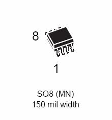
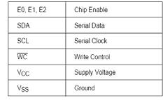
83 K4S161622D-TC80 DSP PART IC14 M24C04 DSP PART IC22 83


84 74VHCT244A DSP PART IC17, IC18, IC25 NJM2068M DSP PART IC31 ~ IC50 PROCESSORR PART IC1.IC4.IC7.IC8.IC9.IC11.IC12.IC13.IC15.IC16.IC17.IC20 IC21.IC23.IC24.IC25.IC26.IC27,IC29,IC30 LC74763M VIDEO PART IC209 84
85 HCA-18LL03 FRONT PART DP71 85

86 KIA78R08API DSP PART IC21 RPM6938-RSIP-A3 FRONT PART RM 71 BU4053BC VIDEO PART IC612 DSP PART IC5 FAROUDJA PART IC15 86


87 CS5361 DSP PART IC27, IC28, IC29, IC30 CS49400 DSP PART IC11 87

88 VPC3230D IC VIDEO DECODER FAROUDJA PART IC10 88
DPR1005 DPR2005 DIGITAL PATH AUDIO/VIDEO RECEIVER
 DPR1005 DPR2005 DIGITAL PATH AUDIO/VIDEO RECEIVER SERVICE MANUAL CONTENTS NOTICES PLEASE READ FIRST......2 ELECTROSTATICALLY SENSITIVE DEVICES.....3 LEAKAGE TESTING.........4 DPR1005 SPECIFICATIONS.......5
AVR135 6 X 40W 6.1 CHANNEL A/V RECEIVER
 AVR135 6 X 40W 6.1 CHANNEL A/V RECEIVER SERVICE MANUAL CONTENTS ESD WARNING.2 LEAKAGE TESTING......3 BASIC SPECIFICATIONS..4 FRONT PANEL CONTROLS......5 REAR PANEL CONNECTIONS. 7 REMOTE CONTROL FUNCTIONS...9
AVR507 Limited Edition Audio/VideoReceiver OWNER S MANUAL
 AVR507 Limited Edition Audio/VideoReceiver OWNER S MANUAL DIGITAL EX LOGIC 7 PRO LOGIC 3 STEREO DSP 7 CH. STEREO SURR. OFF SBL Power for the Digital Revolution Table of Contents 3 Introduction 4 Safety
AVR 5500 Audio/Video Receiver OWNER S MANUAL
 AVR 5500 Audio/Video Receiver OWNER S MANUAL Power for the Digital Revolution Table of Contents 3 Introduction 4 Safety Information 4 Unpacking 5 Front Panel Controls 7 Front Panel Information Display
AVR 745 Audio/Video Receiver
 29510_AVR745_Engelsk 30/10/06 9:31 Side 1 ENGLISH AVR 745 Audio/Video Receiver OWNER S MANUAL 29510_AVR745_Engelsk 30/10/06 9:31 Side 2 Table of Contents 3 Introduction 4 Safety Information 4 Unpacking
AVR 240 AUDIO/VIDEO RECEIVER OWNER S MANUAL. Power for the Digital Revolution. AVR 240 DIGITAL LOGIC 7 VID 1 DVD CD FMAM TAPE VID 2 VID 3 VID 4
 DIGITAL LOGIC 7 VID 1 DVD Power for the Digital Revolution. AVR 240 AUDIO/VIDEO RECEIVER OWNER S MANUAL AVR 240 PRO LOGIC 3 STEREO DSP HEADPHONE 5 7 CH. STEREO SURR. OFF VID 2 VID 3 VID 4 CD FMAM TAPE
AVR 135 AUDIO/VIDEO RECEIVER OWNER S MANUAL. Power for the Digital Revolution. AVR 135 DIGITAL LOGIC 7 VID 1 DVD CD FMAM TAPE 6 8 CH VID 2 VID 3
 DIGITAL LOGIC 7 VID 1 DVD Power for the Digital Revolution. AVR 135 AUDIO/VIDEO RECEIVER OWNER S MANUAL AVR 135 PRO LOGIC 3 STEREO DSP 5 CH. STEREO SURR. OFF VID 2 VID 3 CD FMAM TAPE 6 8 CH C AVR 135 AUDIO/VIDEO
Power for the Digital Revolution. AVR 225 AUDIO/VIDEO RECEIVER OWNER S MANUAL AVR 225
 Power for the Digital Revolution. AVR 225 AUDIO/VIDEO RECEIVER OWNER S MANUAL AVR 225 db AM/FM Tun Mode AUDIO/ VIDEO RECEIVER AVR 225 3 Introduction 4 Safety Information 4 Unpacking 5 Front-Panel Controls
AVR 255/AVR 355 Audio/VideoReceiver OWNER S MANUAL
 ENGLISH AVR 255/AVR 355 Audio/VideoReceiver OWNER S MANUAL AVR Info Resolution Audio Effects Video Modes Surround Modes Back/Exit A B OK L K Source List Composit Table of Contents 3 Introduction 4 Safety
R e c e i v e r. Receiver
 R e c e i v e r Receiver > Eight channels > Eight configurable inputs > Three independent zones > Integrated 7-channel amplifier with massive toroidal transformer and thermal/dc protection > AM/FM tuner
Harman Kardon Audio/VideoReceiver
 AVR80 manual 11/01/98 13:01 Side 1 Harman Kardon AVR80 Audio/VideoReceiver Volume VISUAL TV LD VCR 12 AUX TEST SIGNAL LEVEL CH MEMO AUTO TUNED STEREO db khz MHz STEREO THX CINEMA PRO LOGIC MOVIE HALL MATRIX
B&K Components, Ltd. Reference 10 Reference 20 A/V System Controller. Owner s Manual
 B&K Components, Ltd. Reference 10 Reference 20 A/V System Controller Owner s Manual p/n 12698 Rev. 9808B B&K Components, Ltd., 2100 Old Union Road, Buffalo, New York 14227-2725 p/n 12698 Rev. 9808B TABLE
TV CHANNEL INSTALLATION
 LCD TV TV CHANNEL ATION Immediately after unpacking and plugging in your new television, run the auto program function to set up the TV for the broadcast or cable channels available in your area. If you
HK 3380 Stereo Receiver OWNER S MANUAL
 HK 3380 Stereo Receiver OWNER S MANUAL SPEAKER 1 SPEAKER 2 MUTE AUTO TUNED STEREO RDS PTY CT RT TA MEMORY PRESET SLEEP PHONO FM VID 1 VID 2 AM VID 3 CD TAPE M. Power for the Digital Revolution Table of
PX-600 Multi-Room Preamp/Controller
 PX-600 Multi-Room Preamp/Controller PX-600 Multi-Room Preamp/Controller Power Tuner CD Tape Aux Video Mute All Off Madrigal Audio Laboratories 2081 South Main Street Middletown, CT 06457 A Harman International
AVR 247 AUDIO/VIDEO RECEIVER OWNER S MANUAL
 AVR 247 AUDIO/VIDEO RECEIVER OWNER S MANUAL SAFETY INFORMATION 2 1. Read Instructions. All the safety and operating instructions should be read before the product is operated. 2. Retain Instructions. The
AVR 1550 Audio/Video Receiver OWNER S MANUAL
 AVR 1550 Audio/Video Receiver OWNER S MANUAL Power for the Digital Revolution Table of Contents 3 Introduction 4 Safety Information 4 Unpacking 5 Front Panel Controls 7 Front Panel Information Display
AVR 154 AUDIO/VIDEO RECEIVER OWNER S MANUAL
 AVR 154 AUDIO/VIDEO RECEIVER OWNER S MANUAL SAFETY INFORMATION Important Safety Instructions 1. Read these instructions. 2. Keep these instructions. 3. Heed all warnings. 4. Follow all instructions. 5.
ANTHEM NOW SHIPPING MRX 710 AND MRX 510 A/V RECEIVERS No trade offs: high-end performance with ease of integration.
 PRESS RELEASE Contact: Erin Phillips at pr@paradigm.com ANTHEM NOW SHIPPING MRX 710 AND MRX 510 A/V RECEIVERS No trade offs: high-end performance with ease of integration. Toronto, Canada October 29th,
UNFOLD THE BASE. Quick Start Guide CONTENTS INSTALLING LCD TV ON THE WALL
 Quick Start Guide English CONTENTS INSTALLING LCD TV ON THE WALL.. UNFOLD THE BASE............... TV CHANNEL INSTALLATION........ PRESENTATION OF THE LCD TV..... ACCESSORIES.................... BATTERY
Harman Kardon HK3270 StereoReceiver
 Harman Kardon HK3270 StereoReceiver Volume X AM FM TUNING PRESET SCAN PRESET FM MODE Mute Bass Treble Balance Min Max Min Max L R Owner s Manual Owner s Manual HK3270 Stereo Receiver Table of Contents
HK 3490/HK 3390 Stereo Receiver
 Side 1 English HK 3490/HK 3390 Stereo Receiver Svenska OWNER S MANUAL L K L K Side 2 Table of Contents 3 Introduction 3 Important Information 4 Front Panel Controls 6 Rear Panel Connections 8 Remote Control
Instruction Guide. The TV Jockey Computer Monitor TV Tuner with Remote COMP2VGATVGB. The Professionals Source For Hard-to-Find Computer Parts
 VIDEO ADAPTER The TV Jockey Computer Monitor TV Tuner with Remote COMP2VGATVGB Instruction Guide * Actual product may vary from photo The Professionals Source For Hard-to-Find Computer Parts FCC COMPLIANCE
AVR 7550HD AUDIO/VIDEO RECEIVER OWNER S MANUAL
 AVR 7550HD AUDIO/VIDEO RECEIVER OWNER S MANUAL SAFETY INFORMATION IMPORTANT SAFETY INSTRUCTIONS 1. Read these instructions. 2. Keep these instructions. 3. Heed all warnings. 4. Follow all instructions.
M R X
 MRX 710 / 510 / 310 AWARD-WINNING A/V RECEIVERS ANTHEM ROOM CORRECTION SYSTEM A fantastic-sounding product well worthy of a serious audition don t delay. ~ What Hi Fi on the MRX 700 MRX 710 shown Among
MULTI CHANNEL AV RECEIVERSTR-DH750/STR- DH550
 MULTI CHANNEL AV RECEIVERSTR-DH750/STR- DH550 PROTECTOR The receiver will automatically turn off after a few seconds. Check the followings: There may be an electrical surge or power failure. Unplug the
DSP-AX3200 AV AMPLIFIER AMPLIFICATEUR AUDIO-VIDEO
 GB DSP-AX3200 AV AMPLIFIER AMPLIFICATEUR AUDIO-VIDEO OWNER S MANUAL MODE D EMPLOI BEDIENUNGSANLEITUNG BRUKSANVISNING MANUALE DI ISTRUZIONI MANUAL DE INSTRUCCIONES GEBRUIKSAANWIJZING CAUTION: READ THIS
RX-6000VBK / RX-6008VBK
 MENU ENTER STANDBY SOURCE NAME SOURCE NAME THEATER LIVE CLUB DANCE CLUB HALL PAVILLION ON DIGITAL AUTO D I G I T A L ADJUST SETTING MEMORY AUDIO/VIDEO CONTROL RECEIVER RX-6000VBK / RX-6008VBK SLEEP POWER
RX-E111RSL / RX-E112RSL
 VCR /REW TV/VIDEO SLEEP DIMMER RM-SRXE111R REMOTE HOME CINEMA CENTER TV DIRECT STB VCR TV ANALOG/DIGITAL TAPE FM INPUT ON/OFF PTY( MODE STB RETURN PTY SEARCH ENTER VCR FM MODE TA/NEWS/INFO AUDIO CENTER
AVR 1600 AUDIO/VIDEO RECEIVER OWNER S MANUAL
 AVR 1600 AUDIO/VIDEO RECEIVER OWNER S MANUAL introduction SAFETY INFORMATION Important Safety Instructions 1. Read these instructions. 2. Keep these instructions. 3. Heed all warnings. 4. Follow all instructions.
RX-V596RDS. Natural Sound AV Receiver Ampli-tuner audio-vidéo
 G B RX-V596RDS Natural Sound AV Receiver Ampli-tuner audio-vidéo OWNER S MANUAL MODE D EMPLOI BEDIENUNGSANLEITUNG BRUKSANVISNING MANUALE DI ISTRUZIONI MANUAL DE INSTRUCCIONES GEBRUIKSAANWIJZING CAUTION:
Power for the Digital Revolution. HK 3475 STEREO RECEIVER OWNER S MANUAL HK 3475 MUTE T-MON AUTO TUNED ST SLEEP. VMAx
 Power for the Digital Revolution. HK 3475 STEREO RECEIVER OWNER S MANUAL HK 3475 MUTE T-MON AUTO TUNED ST MEMORY PRESET SLEEP VMAx HK 3475 STEREO RECEIVER 3 Introduction 3 Safety Information 4 Unpacking
AVR 160 AUDIO/VIDEO RECEIVER OWNER S MANUAL
 AVR 160 AUDIO/VIDEO RECEIVER OWNER S MANUAL SAFETY INFORMATION Important Safety Instructions 1. 2. 3. 4. 5. 6. 7. Read these instructions. Keep these instructions. Heed all warnings. Follow all instructions.
Please Read First. Safety Instructions WARNING: TO REDUCE THE RISK OF FIRE OR ELECTRIC SHOCK, DO NOT EXPOSE THIS UNIT TO RAIN OR MOISTURE.
 Please Read First Safety Instructions WARNING: TO REDUCE THE RISK OF FIRE OR ELECTRIC SHOCK, DO NOT EXPOSE THIS UNIT TO RAIN OR MOISTURE. CAUTION: To reduce the risk of electrical shock, do not remove
FD Trinitron Colour Television
 R 4-205-569-32(1) FD Trinitron Television Instruction Manual GB KV-14LM1U 2000 by Sony Corporation NOTICE FOR CUSTOMERS IN THE UNITED KINGDOM A moulded plug complying with BS1363 is fitted to this equipment
Harman Kardon PT2500 A/VSurround Tuner Controller
 PT2500(g).qx 10/23/96 7:36 AM Page 16 Harman Kardon PT2500 A/VSurround Tuner Controller Tuning Volume 1 2 3 4 5 6 7 8 9 0 0-30 Scan Memory DOLBY 3-CH THEATER STADIUM DIRECT MEMORY CENTER MHz MODE FM Tuned
USER MANUAL GOLDMUND MIMESIS 32.5 Universal Acoustic Processor
 USER MANUAL GOLDMUND MIMESIS 32.5 Universal Acoustic Processor Congratulations. Thank you for purchasing the Goldmund MIMESIS 32.5 UNIVERSAL ACOUSTIC PROCESSOR. You have acquired the best multi-usage acoustic
Owner s Manual DRR-2T. Dual Tuner DAB+/FM Digital Radio Tuner Digitalview Australia
 Owner s Manual DRR-2T Dual Tuner DAB+/FM Digital Radio Tuner 2009-2010 Digitalview Australia Table of Contents IMPORTANT SAFETY INSTRUCTIONS...4 Introduction...1 Features of the DRR-2T...2 User Convenience
QIP7232 P2. Hybrid QAM/IP High-definition Set-top. Quick Start Guide
 QIP7232 P2 Hybrid QAM/IP High-definition Set-top Quick Start Guide Before You Begin Introduction Congratulations on receiving a Motorola QIP7232 Hybrid QAM/IP High-definition Set-top. This document will
GDB9 INSTRUCTION MANUAL DIGITAL TERRESTRIAL RECEIVER
 GDB9 INSTRUCTION MANUAL DIGITAL TERRESTRIAL RECEIVER Goodmans Support: www.goodmans.co.uk/support Please read these instructions before use and keep for future reference IMPORTANT SAFETY INSTRUCTIONS Thank
INSTRUCTIONS FOR USE Pro-Ject Receiver Box S
 INSTRUCTIONS FOR USE Pro-Ject Receiver Box S Dear music lover, thank you for purchasing a PRO-JECT AUDIO receiver. In order to achieve maximum performance and reliability you should study these instructions
HK 3390 STEREO RECEIVER OWNER S MANUAL
 HK 3390 STEREO RECEIVER OWNER S MANUAL SAFETY INFORMATION Important Safety Instructions 1. Read these instructions. 2. Keep these instructions. 3. Heed all warnings. 4. Follow all instructions. 5. Do not
Before you can install your LCD TV on the wall, you must fi rst remove the base using the steps below:
 Quick Start Guide English CONTENTS INSTALLING LCD TV ON THE WALL.. TV CHANNEL INSTALLATION........ PRESENTATION OF THE LCD TV...... ACCESSORIES.................... BATTERY INSTALLATION............ REMOTE
Introduction & Features
 Contents Introduction & Features... 3 Connections... 3 Audio Outputs... 4 Video Output... 5 On-Screen Display - The OSD-1... 5 AC Connection... 6 RFD-1 AC-3 RF Demodulator... 7 DTS-1 DTS Decoder... 8 Source
KD-CSW2x1. Operating Instructions. 2 Inputs to 1 Output Component Video/Audio Switcher. KD-CSW2x1 Operating Instructions.
 KD-CSW2x1 2 Inputs to 1 Output Video/ Switcher Operating Instructions Key Digital, led by digital video pioneer Mike Tsinberg, develops and manufactures high quality, cutting-edge technology solutions
Quick Reference Guide
 Multimedia Projector Quick Reference Guide MODEL 103-011100-01 Projection lens is optional. English Use this book as a reference guide when setting up the projector. For detailed information about installation,
AVR 460 AVR 360 AUDIO/VIDEO RECEIVERS. OWNER S MANUAL Basic Functions
 AVR 460 AVR 360 AUDIO/VIDEO RECEIVERS OWNER S MANUAL Basic Functions SAFETY INFORMATION Important Safety Instructions 1. 2. 3. 4. 5. 6. 7. Read these instructions. Keep these instructions. Heed all warnings.
AUDIO/VIDEO CONTROL RECEIVER RX-D701S INSTRUCTIONS LVT A [A]
![AUDIO/VIDEO CONTROL RECEIVER RX-D701S INSTRUCTIONS LVT A [A]](/thumbs/95/124587360.jpg "AUDIO/VIDEO CONTROL RECEIVER RX-D701S INSTRUCTIONS LVT A [A]") AUDIO/VIDEO CONTROL RECEIVER RX-D701S INSTRUCTIONS LVT1437-012A [A] Warnings, Cautions, and Others Caution STANDBY/ON button! Disconnect the mains plug to shut the power off completely. The STANDBY/ON
AUDIO/VIDEO CONTROL RECEIVER RX-D701S INSTRUCTIONS LVT1437-012A [A] Warnings, Cautions, and Others Caution STANDBY/ON button! Disconnect the mains plug to shut the power off completely. The STANDBY/ON
Coax A/V Agile Demodulator Tuner W/IR Remote Control. User Manual (Model: RFDM2 PDK)
") Coax A/V Agile Demodulator Tuner W/IR Remote Control User Manual (Model: RFDM2 PDK) 1. Product Features: RFDM2-PDK Demodulator with IR Remote This coax to composite A/V demodulator is a professional grade
Coax A/V Agile Demodulator Tuner W/IR Remote Control User Manual (Model: RFDM2 PDK) 1. Product Features: RFDM2-PDK Demodulator with IR Remote This coax to composite A/V demodulator is a professional grade
HD Digital Set-Top Box Quick Start Guide
 HD Digital Set-Top Box Quick Start Guide Eagle Communications HD Digital Set-Top Box Important Safety Instructions WARNING TO REDUCE THE RISK OF FIRE OR ELECTRIC SHOCK, DO NOT EXPOSE THIS PRODUCT TO RAIN
M40 80W x 2 Channel Stereo Receiver Installation & User Guide
 Audio Systems M40 80W x 2 Channel Stereo Receiver Installation & User Guide IMPORTANT SAFETY INSTRUCTIONS CAUTION: To reduce the risk of electric shock, do not remove cover (or back). No user-serviceable
CAUTION RISK OF ELECTRIC SHOCK NO NOT OPEN
 Evolution Digital HD Set-Top Box Important Safety Instructions 1. Read these instructions. 2. Keep these instructions. 3. Heed all warnings. 4. Follow all instructions. 5. Do not use this apparatus near
VR-4090/VR-4080 KRF-V7773D B CH (K,P,T,M,X,Y) OC 9911
 OC 9911") VR-4090/VR-4080 KRF-V7773D B60-4645-10 01 CH (K,P,T,M,X,Y) OC 9911 Table of Contents Chapter One: Moving Around... 1 What s on the Front Panel of Your Kenwood Audio - Video Receiver?... 2 What s on the
VR-4090/VR-4080 KRF-V7773D B60-4645-10 01 CH (K,P,T,M,X,Y) OC 9911 Table of Contents Chapter One: Moving Around... 1 What s on the Front Panel of Your Kenwood Audio - Video Receiver?... 2 What s on the
Table of Contents 18 Connection Diagrams 30 Speaker Placement Tips
 NOTE This manual is provided for REFERENCE purposes only. Information contained in this manual, including contact and warranty information, may NOT be current or correct. Table of Contents 3 Thank You
This symbol indicates that there are important operating and maintenance instructions in the literature accompanying this unit.
 BeoSystem 1 Guide CAUTION: To reduce the risk of electric shock, do not remove cover (or back). No User-serviceable parts inside. Refer servicing to qualified service personnel. WARNING: To prevent fire
AV Receiver. Owner s Manual. English for U.S.A.
 Receiver Owner s Manual English for U.S.A. CONTENTS INTRODUCTION Features and capabilities...4 Using the TV OSD to operate the unit...5 View or modify content for the current input source ...5
of Switzerland of Switzerland Re:source FM Tuner Module Dominating Entertainment. Revox of Switzerland.
 of Switzerland of Switzerland FM Tuner Module Dominating Entertainment. Revox of Switzerland. Contents FM Tuner module Installation Connections Tuner menu Tuner operation Station searching Manual station
Digital Home Theater Receivers Yamaha takes home theater receivers to new levels of quality, versatility and convenience.
 Yamaha takes home theater receivers to new levels of quality, versatility and convenience. The RX-V2700BL is the perfect component to build a high performance home theater system around. Both audio and
ORPHEUS ZERO U S E R M A N U A L
 ORPHEUS ZERO U S E R M A N U A L I N T R O D U C T I O N FEATURES Class 1 product CD drive (ORPHEUS ZERO Drive) or player (ORPHEUS ZERO Player) Multiple formats reader : CD, CD-R, CD-RW Software controlled
39" 1080p LCD Television PLCD3992A
 PROSCAN 39" 1080p LCD Television PLCD3992A Contents Contents Caution Safety Information Unit and Accessories Product Feature 2 3 4 4 Introduction 5-9 1. Front View 5 2. Rear View 6 3. Instruction for
The Outlaws Guide to the Marantz SR5004
 The Outlaws Guide to the Marantz SR5004 Marantz SR5004 7.1 Channel Receiver Version 1.02 Marantz is a registered trademark of D&M Holdings Outlaw and cowboy logo are registered trademarks of Outlaw Audio,
Wireless 5.8GHz AV Sender With Built in Remote Control Extender
 Wireless 5.8GHz AV Sender With Built in Remote Control Extender AR-1913 User Manual TABLE OF CONTENTS Box Contents..................2 User Guide.............3 Installation............4 Trouble Shooting............
P XGA TFT Monitor. User s Manual
 P6151 15 XGA TFT Monitor User s Manual Disclaimers This manual has been carefully checked and believed to contain accurate information. Axiomtek Co., Ltd. assumes no responsibility for any infringements
Evolution Digital HD Set-Top Box Important Safety Instructions
 Evolution Digital HD Set-Top Box Important Safety Instructions 1. Read these instructions. 2. Keep these instructions. 3. Heed all warnings. 4. Follow all instructions. 5. Do not use this apparatus near
Be sure to run the vehicle engine while using this unit to avoid battery exhaustion.
 CAUTION: TO REDUCE THE RISK OF ELECTRIC SHOCK DO NOT REMOVE COVER (OR BACK) NO USER-SERVICEABLE PARTS INSIDE REFER SERVICING TO QUALIFIED SERVICE PERSONNE; Please Read all of these instructions regarding
RX-975 AM/FM Stereo Receiver. Owner s Manual
 RX-975 AM/FM Stereo Receiver Owner s Manual RX-975 AM/FM Stereo Receiver 2 WARNING: There are no user serviceable parts inside. Refer all servicing to qualified service personnel. WARNING: To reduce the
P-2 Installing the monitor (continued) Carry out as necessary
 Carry out as necessary") P-2 Installing the monitor (continued) Carry out as necessary Using the monitor without the bezel MDT552S satisfies the UL requirements as long as it is used with the bezel attached. When using the monitor
P-2 Installing the monitor (continued) Carry out as necessary Using the monitor without the bezel MDT552S satisfies the UL requirements as long as it is used with the bezel attached. When using the monitor
Acer LCD TV AT2001 User's Guide
 Acer LCD TV AT2001 User's Guide Copyright 2005. Acer Incorporated. All Rights Reserved. Acer AT2001 User' s Guide Original Issue: May 2005 Acer and the Acer logo are registered trademarks of Acer Incorporated.
CAR-5N / CAR-5P Video to RGB Converter for CAR display. Operation Manual
 CAR-5N / CAR-5P Video to RGB Converter for CAR display Operation Manual TABLE OF CONTENTS 1. Introduction... 1 2. Features... 1 3. Package Contents... 1 4. Operation Controls and Functions... 2 4.1 Front
Integrator s Guide Avalon
 Integrator s Guide Avalon HD Component Video / Digital Audio Matrix Switch 2 Table of Contents Table of Contents... 2 Introduction... 3 Features:... 3 Installation... 4 Unpacking... 4 Front Panel Protective
Model CMX3838A2 AV Matrix Switch with DSP audio (firmware 1.0)
") Model CMX3838A2 AV Matrix Switch with DSP audio (firmware 1.0) Overview: This product is a full featured video & audio matrix switch. It is most commonly used to independently distribute video & audio
Model CMX3838A2 AV Matrix Switch with DSP audio (firmware 1.0) Overview: This product is a full featured video & audio matrix switch. It is most commonly used to independently distribute video & audio
RX-V357. AV Receiver Ampli-tuner audio-vidéo
 G RX-V357 AV Receiver Ampli-tuner audio-vidéo OWNER S MANUAL MODE D EMPLOI BEDIENUNGSANLEITUNG BRUKSANVISNING GEBRUIKSAANWIJZING ИНСТРУКЦИЯ ПО ЭКСПЛУАТАЦИИ CAUTION: READ THIS BEFORE OPERATING YOUR UNIT.
ZR-4 SERIES 2 MULTIZONE RECEIVER KIT
 NILES AUDIO CORPORATION ZR-4 SERIES 2 MULTIZONE RECEIVER KIT SYSTEM DESIGN GUIDE INCLUDES: ZR-4 SERIES 2 OVERVIEW ZR-4 SERIES 2 SYSTEM APPLICATIONS ZR-4 SERIES 2 MULTIZONE RECEIVER KITS APPLICATION NOTES
RX-V620RDS Natural Sound AV Receiver Ampli-tuner audio-vidéo
 G B RX-V620RDS Natural Sound AV Receiver Ampli-tuner audio-vidéo OWNER S MANUAL MODE D EMPLOI BEDIENUNGSANLEITUNG BRUKSANVISNING MANUALE DI ISTRUZIONI MANUAL DE INSTRUCCIONES GEBRUIKSAANWIJZING CAUTION:
FV400 DIGITAL TV RECEIVER WITH MODULATOR INSTRUCTION MANUAL
 FV400 DIGITAL TV RECEIVER WITH MODULATOR INSTRUCTION MANUAL Please read this instruction manual carefully before using your receiver Table of Contents Introduction-----------------------------------------------------------------------------
Elegance Series Components / New High-End Audio Video Products from Esoteric
 Elegance Series Components / New High-End Audio Video Products from Esoteric Simple but elegant 3 inch height achieved in a new and original chassis Aluminum front panel. Aluminum and metal casing. Both
MC-12HD Digital Controller User Guide
 MC-12HD Digital Controller User Guide IMPORTANT SAFETY INSTRUCTIONS 1. Read these instructions. 2. Keep these instructions. 3. Heed all warnings. 4. Follow all instructions. 5. Do not use this apparatus
isync HD & isync Pro Quick Reference Guide isync HD isync Pro Digital Video Processor and Video/Audio Switcher
 isync HD & isync Pro Digital Video Processor and Video/Audio Switcher Quick Reference Guide isync HD Key Digital, led by digital video pioneer Mike Tsinberg, develops and manufactures high quality, cutting-edge
To the Users of AITech s Wireless pc2tv Upgrade Kit:
 To the Users of AITech s Wireless pc2tv Upgrade Kit: Important Safety Precautions: 1. To prevent fire or shock hazard, do not expose this product to rain or moisture. Do not use near a bathtub, sink or
Stereo Cassette Deck
 3-858-050-11(1) Stereo Cassette Deck Operating Instructions 199 by Sony Corporation 3-858-050-11 (1) WARNING To prevent fire or shock hazard, do not expose the unit to rain or moisture. To avoid electrical
MODEL AVP1/APV1P DOLBY DIGITAL DTS PROCESSOR/PREAMPLIFIER OWNERS MANUAL
 MODEL AVP1/APV1P DOLBY DIGITAL DTS PROCESSOR/PREAMPLIFIER OWNERS MANUAL AVP1/ AVP1P OWNERS MANUAL INTRODUCTION Congratulations on your PERREAUX Model AVP1 purchase. To realise the full potential of your
Model Channel Preamplifier Processor
 Model 970 7.1 Channel Preamplifier Processor Owner s Manual Version 1.0 Warnings Please Read First CAUTION: To reduce the risk of electric shock, do not remove the cover. No user serviceable parts inside.
HD-1603 Single Input MPEG-4 DVB-T HD Encoder/Modulator User Guide and Install Manual
 ZyCastR digi-mod HD Range digi-mod HD-1603 www.digi-modbyzycast.com HD-1603 Single Input MPEG-4 DVB-T HD Encoder/Modulator User Guide and Install Manual Table of Contents www.digi-modbyzycast.com Safety
Home Theater System HT-1800DP. Operating Instructions. Owner s Record (2) 2003 Sony Corporation
 2003 Sony Corporation") 4-244-184-11(2) Home Theater System Operating Instructions Owner s Record The model and serial numbers are located at the rear of the unit. Record the serial number in the space provided below. Refer to
4-244-184-11(2) Home Theater System Operating Instructions Owner s Record The model and serial numbers are located at the rear of the unit. Record the serial number in the space provided below. Refer to
Stereo Cassette Deck
 3-864-773-11(1) Stereo Cassette Deck Operating Instructions TC-SD1 1998 by Sony Corporation WARNING WARNING To prevent fire or shock hazard, do not expose the unit to rain or moisture. To avoid electrical
UltraPioneerAVR3 HSPI User s Guide A HomeSeer HS3 plug-in to enable control of Pioneer A/V Receivers that support the IP & RS232 control system.
 UltraPioneerAVR3 HSPI User s Guide A HomeSeer HS3 plug-in to enable control of Pioneer A/V Receivers that support the IP & RS232 control system. Copyright 2014 ultrajones@hotmail.com Revised 01/20/2014
RX-V530RDS. AV Receiver Ampli-tuner audio-vidéo
 GB RX-V530RDS AV Receiver Ampli-tuner audio-vidéo OWNER S MANUAL MODE D EMPLOI BEDIENUNGSANLEITUNG BRUKSANVISNING MANUALE DI ISTRUZIONI MANUAL DE INSTRUCCIONES GEBRUIKSAANWIJZING CAUTION: READ THIS BEFORE
Quick Start Guide. Digital Research Technologies Inc. 4 Marconi, Irvine, CA For: DLCD26, DLCD32, DLCD42 & DLCD42P LCD Televisions
 Quick Start Guide Digital Research Technologies Inc. 4 Marconi, Irvine, CA 92618 For: DLCD26, DLCD32, DLCD42 & DLCD42P LCD Televisions 1 Distance recommendations: Always position the LCD TV set where sufficient
Application Note M7L VideoPad-AV Installation Setup (software 9.1 onwards)
") Installation Guidelines The VideoPad-AV should be installed within a double UK electrical box at least 35mm deep. The electrical box must only have screw lugs fitted on the left and right sides. The VideoPad-AV
Installation Guidelines The VideoPad-AV should be installed within a double UK electrical box at least 35mm deep. The electrical box must only have screw lugs fitted on the left and right sides. The VideoPad-AV
Connevans.info. DeafEquipment.co.uk. This product may be purchased from Connevans Limited secure online store at
 Connevans.info Solutions to improve the quality of life Offering you choice Helping you choose This product may be purchased from Connevans Limited secure online store at www.deafequipment.co.uk DeafEquipment.co.uk
AVR 460 AVR 360 AUDIO/VIDEO RECEIVER. OWNER S MANUAL Advanced Functions
 AVR 460 AVR 360 AUDIO/VIDEO RECEIVER OWNER S MANUAL Advanced Functions SAFETY INFORMATION Important Safety Instructions 1. Read these instructions. 2. Keep these instructions. 3. Heed all warnings. 4.
Trinitron Color TV KV-XF21M80. Operating Instructions (1)
") 3-866-0- () Trinitron Color TV Operating Instructions Before operating the unit, please read this manual thoroughly and retain it for future reference. GB CT CS KV-XFM80 999 by Sony Corporation WARNING
3-866-0- () Trinitron Color TV Operating Instructions Before operating the unit, please read this manual thoroughly and retain it for future reference. GB CT CS KV-XFM80 999 by Sony Corporation WARNING
USER S MANUAL MANUEL DE L UTILISATEUR MANUAL DEL USUARIO EW39T4LZ
 USER S MANUAL MANUEL DE L UTILISATEUR MANUAL DEL USUARIO EW39T4LZ Contents Contents Caution Safety Information Unit and Accessories Product Feature 2 3 4 4 Introduction 5-9 1. Front View 5 2. Rear View
CP-255ID Multi-Format to DVI Scaler
 CP-255ID Multi-Format to DVI Scaler Operation Manual DISCLAIMERS The information in this manual has been carefully checked and is believed to be accurate. Cypress Technology assumes no responsibility
M5-H002. Multiview T-35. DVB-T to PAL / 5 channels on all TV s
 120531 M5-H002 Multiview T-35 DVB-T to PAL / 5 channels on all TV s Contents Multiview... 3 Features... 3 Caution... 3 Front & Rear Panel... 4 Connecting... 5 Programming... 6 Information... 7 Installation...8
Component Video Matrix Switcher Series ITEM NO.: YS04MA, YS04MD
 Component Video Matrix Switcher Series ITEM NO.: YS04MA, YS04MD Our component video switcher allows four different component video and stereo/digital audio sources to share two video displays. Manage multiple
AU-A300 Integrated 2 Channel Zone Amplifier OPERATION MANUAL
 AU-A300 Integrated 2 Channel Zone Amplifier OPERATION MANUAL DISCLAIMERS The information in this manual has been carefully checked and is believed to be accurate. CYP (UK) Ltd assumes no responsibility
INSTRUCTIONS FOR USE Pro-Ject Tuner Box S
 INSTRUCTIONS FOR USE Pro-Ject Tuner Box S Dear music lover, thank you for purchasing a Pro-Ject Audio Systems FM-tuner. In order to achieve maximum performance and reliability you should study these instructions
RX-V3200. AV Receiver OWNER S MANUAL
 U RX-V3200 AV Receiver OWNER S MANUAL IMPORTANT Please record the serial number of this unit in the space below. MODEL: Serial No.: The serial number is located on the rear of the unit. Retain this Owner
WARNING: To prevent fire or electric shock, do not expose this appliance to rain or moisture.
 BeoVision 5 Guide 3 NOTE: This equipment has been tested and found to comply with the limits for a class B digital device, pursuant to part 15 of the FCC Rules. These limits are designed to provide reasonable