After more than three decades of extensive material research, device development, and heavy investment on advanced
|
|
|
- Priscilla Riley
- 5 years ago
- Views:
Transcription
1 Analytical equation for the motion picture response time of display devices Fenglin Peng 1,a), Haiwei Chen 1,a), Fangwang Gou 1, Yun-Han Lee 1, Michael Wand 2, Ming-Chun Li 3, Seok-Lyul Lee 3, and Shin-Tson Wu 1,b) 1 College of Optics and Photonics, University of Central Florida, Orlando, FL 32816, USA 2 LC Vision, 4150 Darley Ave. Suite 10, Boulder, CO 80305, USA 3 AU Optronics Corp., Hsinchu Science Park, Hsinchu 300, Taiwan Motion picture response time (MPRT) affects the image blurs of thin-film transistor (TFT) liquid crystal displays (LCDs) and organic emitting diode (OLED) displays. We derive an analytical equation to correlate MPRT with LC/OLED response time and TFT frame rate. Good agreement between our physical model and experimental results is obtained. Based on our model, we find that if the LC s response time is 2 ms or less, then its MPRT is nearly the same as that of OLED, even if OLED s response time is assumed to be 0. To achieve MPRT comparable to OLEDs, we developed an ultra-low viscosity LC mixture for vertical alignment mode operation. The measured average gray-to-gray response time is 0.93 ms, and its MPRT at 120 Hz is 6.88 ms. In comparison, OLED s MPRT is 6.67 ms. To further shorten MPRT, we could either increase the frame rate or reduce the backlight duty ratio. Pros and cons of these approaches are discussed. I. INTRODUCTION After more than three decades of extensive material research, device development, and heavy investment on advanced manufacturing technologies, thin-film-transistor liquid crystal displays (TFT LCDs) have become ubiquitous in our daily lives. 1 Its widespread applications span from TVs, monitors, tablets, to smartphones. In addition, displays for gaming monitors and virtual reality (VR) systems are growing rapidly, which demand a higher resolution density, more vivid colors, and unnoticeable image blur. Lately, LCD versus OLED (organic light emitting diode), who wins? is a heated debate topic. 2, 3 Each technology has its own merits and demerits. Generally speaking, LCD is leading in lifetime, peak brightness, and cost; it is comparable to OLED in resolution density, power consumption, ambient contrast ratio and viewing angle, but inferior to OLED in black state, panel flexibility, color gamut, and response time. Therefore, LCD camp has devoted a great deal of efforts to narrowing the performance gap against OLED, including quantum-dot backlight 4, 5 for achieving wider color gamut and lower power consumption, and local dimming 6 to enhance the dynamic contrast ratio to 1,000,000:1. The remaining grand challenge for LCDs is response time; especially nematic LCDs suffer ~100x slower response time than OLED (~0.1 ms). Thus, it is commonly perceived that LCDs exhibit more severe image blurs than OLEDs for the fastmoving objects. 3 To improve LC response time, several approaches have been investigated, e.g. polymer-stabilized blue phase LCs 7, 8, low viscosity nematic LCs 9-11, and ferroelectric LCs. 12 Nevertheless, it remains challenging for nematic LCs to achieve ~0.1 ms while keeping a low operation voltage. a) F. Peng and H. Chen contributed equally to this work. b) Electronic mail: swu@ucf.edu
2 The image blur of a TFT LCD (or OLED) is governed by two important parameters: LC (or OLED) response time and 13, 14 TFT sample and hold time. Motion Picture Response Time (MPRT) has performance of a moving object as: been proposed to quantify the visual MPRT (ms) = BEW (pixel) /v (pixel/frame) T f (ms/frame). (1) Here, BEW stands for the perceived blurred edge width, which is proportional to the object s moving speed (v), and T f is the TFT s frame time (unit: ms), which is the inverse of frame rate (f, unit: Hz): f 1000 / T f. (2) Both TFT LCDs and OLEDs are hold-type displays, that means, the displayed image is hold on by TFTs in a given frame time. As a result, they both suffer from different degree of image blurs, depending on the frame rate and response time. That is to say, OLED could still exhibit motion blurs even if its response time is zero. 15 Recently, Chen et al 16 reported a fast-lcd with MPRT comparable to OLED, but the physical origin of MPRT is not discussed. Unlike LCD and OLED, CRT (cathode ray tube) is an impulse-type display, whose MRPT 1.5 ms and is free from motion blur. 17 The required MPRT depends on the specific applications. For example, if a smartphone or monitor is mainly intended for static images, then a slow MPRT does not affect the display performance. But to clearly display an object moving at speed v =480 pixels per second, the required MPRT should be less than 4 ms. If the speed doubles, then the required MPRT should be faster than 2 ms. Presently, most LCD and OLED TVs are operated at 120 Hz (i.e. MPRT~6.66 ms), thus image blur remains noticeable for the fastmoving objects. There is an urgent need to reduce MPRT to ~1.5 ms (or faster) to eliminate motion blurs. To obtain such a fast MPRT, several approaches have been proposed 14 such as: 1) Employing a pursuit camera to reproduce the BEW and then calculate the MPRT based on Eq. (1), and 2) Using the time based image integration to simulate it. However, these methods are less straightforward and even require complicated experimental setups. In this paper, we analyze the origins of MPRT and derive a simple equation to correlate the MPRT with LC response time and TFT frame rate. Therefore, the MPRT can be calculated easily based on the measured LC response time and the operation frame rate. Good agreement is obtained between the equation, rigorous simulation results and experimental results. Through our analyses, we find that if the LC s response time is 2 ms or less, then its MPRT is nearly the same as that of OLED, even if OLED s response time is assumed to be 0. In experiment, we prepared three ultra-low viscosity LC mixtures and used them in vertical alignment (VA) mode 18 for TVs and fringing field switching (FFS) mode 19 for smartphones. With overdrive and undershoot driving scheme, the measured average gray-to-gray (GTG) response time is only 0.93 ms for the VA cell and 2.95 ms for the FFS cell, and their average GTG MPRT is comparable to that of OLED at the same frame rate. By increasing frame rate and/or decreasing the backlight duty ratio, we can achieve MPRT < 1.5 ms. 2
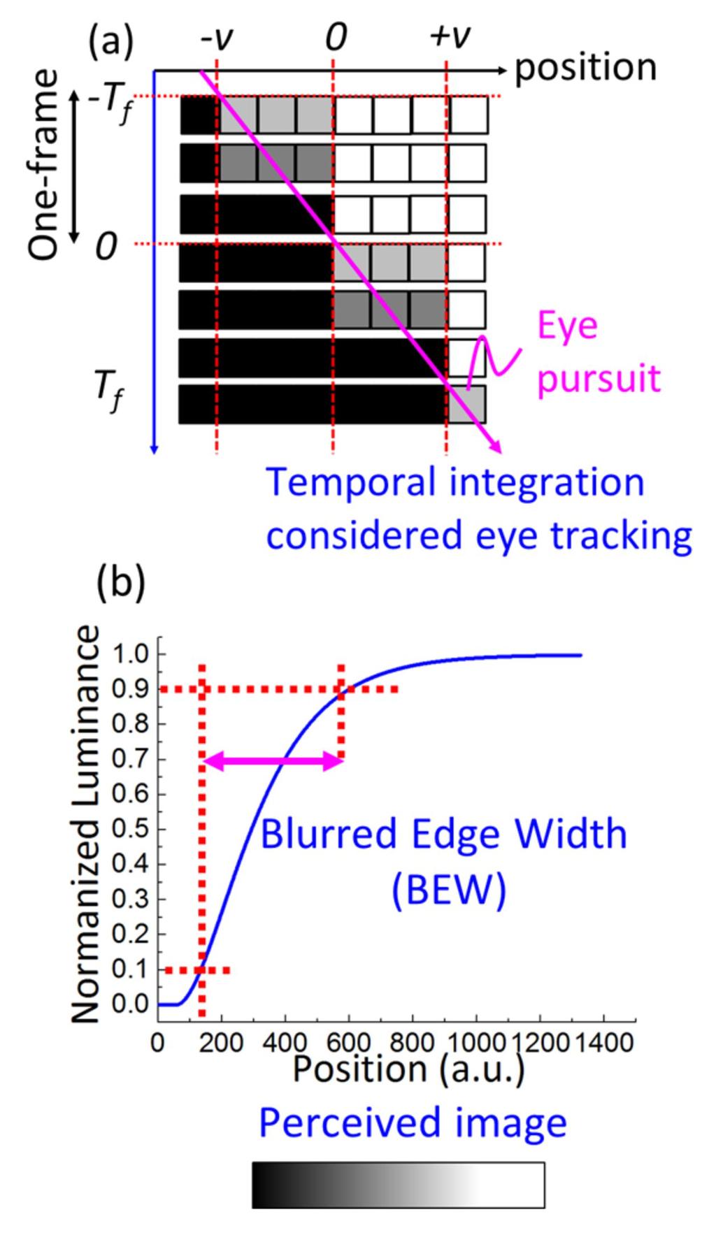
3 II. SIMULATION MODEL FIG. 1. (a) Illustration of the eye tracking a moving bright object on a dark background. (b) The perceived image blur and position dependent normalized luminance. Figure 1(a) illustrates a simple example about the eye tracking a bright moving object on a dark background. Here, the display is a hold-type display, 20 i.e. the object is still on the panel within one frame time and jumps to another positon with speed v. However, human eyes smoothly pursuit the object with the speed v h. Generally, we assume that v h = v. This discrepancy between the hold-type display and human vision system results in image blurs on retina. The perceived motion picture blur (Fig. 1 (b)) is determined by the sum of the pixel s intensity along the motion trajectory within one frame period. The position-dependent luminance curve is plotted in Fig. 1(b) and the blurred edge width is defined as the space interval between 10% and 90% luminance change. 21 The BEW depends on the moving speed: the faster the moving speed, the more 3
4 severe image blurs a human eye can observe. To determine MPRT, several approaches have been investigated, such as employing pursuit camera method and using time based image integration. 14 The pursuit camera approach can reproduce the BEW and calculate the MPRT by using Eq. (1), however, how the LC response affects the MPRT cannot be extracted quantitatively through this method. On the other hand, the time based image integration approach has been demonstrated to be a better way to correlate the liquid crystal response curve (LCRC) with the motion picture response curve (MPRC). MPRC is related to the LC response curve in conjunction with eye-tracking and temporal integration as follows 22, 23 : 1 t T f ' ' MPRC(t) T (t ) dt. (3) T t f In Eq. (3), MPRC represents the normalized luminance profile of the blurred image in the temporal domain and T is the output time-dependent transmittance curve, which is jointly determined by the LC response curve and backlight modulation. Figures 2(a) and 2(b) depict the output time-dependent transmittance curve without and with backlight modulation, respectively. MPRC(t) can be derived from the output time-dependent transmittance by applying one-frame-time moving window function (Fig. 2(c)) as: 23 1 MPRC(t) [ T (t)* H(T f )], (4) T f where * denotes the convolution operation and H(T f ) is the rectangle function with width of T f. FIG. 2. Illustration of output time-dependent transmittance curve on hold-type displays: (a) without backlight modulation and (b) with backlight modulation. The duty ratio of backlight is A/T f. (c) LC response curve and oneframe-time moving window. (d) Illustration of MPRC of LC and OLED at f = 120Hz and the starting point t 0 = 0. 4
5 Let us first consider the simplest case without backlight modulation. Under such condition, T(t) is simply the LC response curve. For a VA cell, the time-dependent optical decay curve T LC_decay (t) has been solved analytically as: 24 T LC _ decay 2 1d 0 2 K33 2 0exp( 2 t 0) () t sin ( ), (5) 2, (6) where 0 is the phase retardation change, 0 stands for the LC director reorientation time, which is determined by the LC visco-elastic coefficient ( 1 /K 33 ) and cell gap d. However, 0 is difficult to measure directly. In experiment, we measure the LC optical response time ( ), which is defined as the time interval between 10% and 90% transmittance change. For a VA cell under small angle approximation, the optical decay time d =a 0, where a , depending on the initial 0 value. 24 On the other hand, the optical rise curve (T LC_rise (t)) of the VA cell is much more complicated because it also depends on the applied voltage 24 : T 2 () t sin ( ), 2t 1 [ 1]exp( ) 2 0 LC _ rise r (7) r 0. V 2 ( ) 1 V th (8) In Eqs. (7) and (8), and 0 represent the tilt angle at t and t = 0, V is the applied voltage and V th is the threshold voltage. From Eq. (8), the rise time could be slow when V is slightly above V th. To overcome this shortcoming, overdrive and undershoot voltage method 25 has been commonly used to speed up the rise time. Therefore, the LC response time is mainly limited by the decay time. Eq. (3) can be derived from the LC response curve by applying one-frame-time moving window function. Therefore, the starting point of MPRC is affected by the tailing transmittance of the previous frame, which makes the MPRC calculation more complicated. To elucidate the derivation procedures without losing its generality, let us assume that the rise-response curve is symmetric to the decay curve (i.e. r = d ): 0; for t t TLC _ rise(t) 2 0exp( 2( t t0) 0) 1 sin ( ); for t t0 2 0 (9) That means at t = t 0, the LCD is switched from the darkest state (T = 0) to the brightest state (T = 1), and the transition time is equal to that of decay process. Therefore, the MPRC can be obtained by simultaneously solving Eqs. (9) and (4). In Fig. 2(d), 5
6 the MPRC of OLED is also included as benchmark for comparison and we assume its response time is 0. Similar to LC response time, MPRT is also defined as the time interval between 10% and 90% luminance change, as Fig. 2(d) depicts. Substituting Eq. (9) into Eq. (4), we find: t0 t 1 ' ' TLC _ rise (t )dt ; if t0 t Tf t0, T f t0 MPRC(t) t T f 1 ' ' TLC _ rise (t )dt ; if t Tf t0. T f t (10) To simplify the derivation process, let us assume t 0 = 0. After Taylor s expansion and only keeping the first and second order terms, we derive the following time-dependent MPRC: t Tf 16 0 t [exp( ) 1] ; for 0 t Tf, MPRC(t) t Tf Tf ( )exp( )[1 exp( )] ; for t Tf. Tf (11) MPRT can be obtained by taking the time interval between 10% and 90% luminance change. From Eq. (11), we find that MPRT is jointly determined by the LC response time ( a 0 ) and TFT frame time (T f ). In general, we can use numerical method to plot the MPRC [Eq. (11)] and then obtain the MPRT. But it would be highly desirable if we can derive an analytical expression for MPRT and comprehend how the LC response time and TFT frame time affect MPRT. To obtain an analytical solution, let us first consider two extreme conditions without backlight modulation: 0 and >> T f. When the LC response time is very fast, we set 0 0 and Eq. (11) is simplified as: t/ Tf, if t Tf MPRC(t), 1, if t Tf (12) Such a MPRC is plotted in Fig. 2(d) (black line). From Fig. 2(d), we find the limiting MPRT 0.8T f. Note: the coefficient 0.8 originates from the MPRT definition, which is from 10% to 90% luminance change. Under such a condition, as the TFT frame rate (f) increases (i.e. T f decreases), the limiting MPRT decreases linearly. On the other hand, if the TFT frame rate is so fast that the LC cannot follow, i.e. >> T f, the one-frame time window can be regarded as a pulse function, and Eq. (4) can be simplified as: MPRC(t) T (t)* (t) T (t). (13) Therefore, MPRC overlaps with the LC response curve (T(t)), i.e. MRPT, which is independent of the frame rate and is solely determined by the LC response time. 6
7 To satisfy these two boundary conditions, based on the eye pursuit tracking diagram shown in Fig. 1(a) we propose the following equation to correlate MPRT with LC response time ( ) and frame time (T f ): 2 2 MPRT (0.8 T f ). (14) To validate Eq. (14), we compare the MPRT results with the simulated ones without approximation. Results are plotted in Fig. 3(a), where the solid lines represent Eq. (14) at the specified frame rates, and the dots are the simulation results using Eqs. (4) and (9) without approximation. The agreement between the rigorous simulation and Eq. (14) is very good. With Eq. (14), we can see easily how the LC response time and TFT frame rate affect MPRT. FIG. 3. (a) LC response time vs. MPRT. Solid lines represent the calculated results from Eq. (14) and dots are simulation results using Eqs. (4) and (9). (b) Open circles and triangles are experimental data measured with HCCH VA mode at f = 120Hz and 240Hz. Pluses and crosses are experimental data reported in Ref. 14. From Fig. 3(a), we find three important trends: (1) At a given frame rate, say 120 Hz, as the LC response time decreases, MPRT decreases almost linearly and then gradually saturates. Note that the MPRT for = 2 ms is only 4% longer than that of = 0. Therefore, if an LCD s response time is 2 ms, then its MPRT is comparable to that of an OLED, even if the OLED s response time is assumed to be 0. (2) As the TFT frame rate increases, the limiting MPRT (assuming = 0) decreases 7
8 linearly, because the limiting MPRT = 0.8T f. (3) If the LC response time is not fast enough, say = 5 ms, then increasing the frame rate from 60 Hz to 120 Hz makes a big improvement in MPRT, but further increasing the frame rate to 240 Hz and 480 Hz the improvement is less obvious. This prediction is consistent with those observed experimentally. 26 Besides LC response time, another factor affecting the output transmittance T(t) is the backlight modulation, as depicted in Figs. 2(a) and 2(b), where A stands for the time that backlight (e.g. LED) is turned on in one frame time. The duty ratio (DR) is defined as: DR A T f. (15) The MPRC can be calculated numerically using Eq. (4). As T(t) becomes discontinuous in one frame and it is determined jointly by the LC response time and the backlight modulation, so that it is quite complicated to get the analytical expression for MPRC. If the LC response time is fast (e.g. 2 ms), then the LC directors can achieve final gray-level when the backlight is turned on. Thus, T(t) can be simplified by the periodic rectangle function [red lines in Fig. 2(b)]. After taking the convolution, MPRC increases with time linearly. Therefore, the MPRT can be expressed as: MPRT 0.8 T DR 800 DR / f. (16) From Eq. (16), we can achieve a fast MPRT by reducing the duty ratio or increasing the frame rate. We will discuss the duty ratio effects later. III. EXPERIMENTAL RESUTLS To validate our findings, we measured the MPRT of two commonly employed LC modes: VA and FFS. Multi-domain VA LCDs have been widely used in large-size TVs and monitors because of their high contrast ratio and low operation voltage. On the other hand, FFS mode has advantages in wide view, weak color shift and pressure resistance for touch panels. Thus, FFS mode is commonly used in touch panel displays, such as smartphones and tablets. Depending on the sign of dielectric anisotropy (Δε), FFS can be categorized into positive type (p-ffs) and negative type (n-ffs). 27 A. Material development Table I lists the compound structures employed in the LC mixture, designated as MX Six major ingredients are included. The homologues (R=1 to 5) of compound 1, compounds 2 and 3 show large dielectric anisotropy and high clearing point. Their clear points range from 160ºC to 190ºC, which help to widen the nematic range. However, their visco-elastic coefficient and activation energy are relative large, as the molecules are quite long and bulky. Therefore, components 4 and 5 are doped to reduce the viscosity. Component 5 also introduces a strong lateral dipole with the 2, 3-difluoroaryl group which helps to maintain a reasonable. In addition, we added component 6 (R = 0 to 3 carbon alkyl chain) to lower the threshold f voltage and melting point. 8
9 TABLE I. Chemical structures of the components in MX We also prepared another negative LCs, HCCH (abbreviated as HCCH; provided by HCCH, China). The clearing point is higher than 100 C, so it can be employed for the applications at extreme environments, such as vehicle and outdoor displays. These two negative LCs can be used in VA and n-ffs modes. In experiment, we filled MX and HCCH into two VA cells (d = 3.3 m) and two n-ffs cells (d = 3.3 m). Besides, a positive LC (DIC-LC2) 28 was also used for investigating the MPRT of p-ffs cell (d = 3.6 m). The physical properties of these three mixtures are summarized in Table II, including melting point (T m ), clearing point (T c ) dielectric anisotropy (Δε), birefringence (Δn), elastic constants (K 11, K 22, and K 33 ) and rotational viscosity (γ 1 ). B. LC response time and MPRT TABLE II. Physical properties of the four LC mixtures at T = 22 C and λ = 550 nm. LCs T m ( C) T c ( C) n K 11 (pn) K 22 (pn) K 33 (pn) γ 1 (mpas) MX < HCCH < DIC-LC2 < In Fig. 3(b), we plot the GTG LC response time vs. MPRT at f = 120 Hz (open circles) and 240 Hz (triangles) for the HCCH VA cell. Overdrive and undershoot method was applied to achieve faster response time. For the convenience of discussion, let us assume the switching takes place between gray level 2 and gray level 5. During the rising period, we applied a 9
10 maximum available voltage for a short period (~1 ms) to accelerate the LC directors from level 2 to level 5, and then followed by a holding voltage to keep the transmittance at gray level 5. To achieve fast decay time, we removed the voltage of gray level 5 for a short period and then followed by a holding voltage to keep the transmittance at gray level 2. By doing so, we can shorten the rise time and decay time by 2x 3x. The solid lines in Fig. 3(b) represent Eq. (14) at four different frame rates. Good agreement is obtained between experiment and Eq. (14). We also include the experimental data taken at f = 60 Hz and 120 Hz from Ref. 14 for comparison. Good agreement is also found. FIG. 4. For VA mode, the measured GTG LC response time of (a) MX and (b) HCCH. The corresponding GTG MPRT at f = 120Hz for (c) MX and (d) HCCH. Figures 4(a)-(d) show the measured GTG LC response time and its corresponding MPRT at f = 120 Hz for VA cells with MX and HCCH. For n-ffs and p-ffs modes, the measured GTG LC response time and MPRT are plotted in Figs. 5(a)-(d). Table III summarizes the average GTG LC response time and MPRT at different frequencies. In our VA cell with MX (and HCCH), its average GTG response time is 0.93 ms (and 1.56 ms), which is 6.1x (and 3.6x) faster than that of a commercial LCD. 3 The average GTG MPRT of both VA cells is only ~3% slower than that of OLED at the same frame rate (e.g. f = 120 Hz). That is to say, these VA LCDs exhibit comparable motion image blurs to OLEDs, except for some slower gray level transitions, e.g. from gray level 8 to 1. Besides, HCCH has a slightly higher birefringence, thus its required cell gap can be reduced to d ~ 3 µm. By doing so, the response time can be reduced by ~20%. For mobile phones and tablets using FFS mode, the frame rate is f = 60 Hz or lower in order to reduce power consumption. From Table III, at f = 60 Hz the 10

11 MPRT of p-ffs and n-ffs is 3% and 12% slower than that of OLED, respectively. However, the mobile phones and tables are intended for static images, which do not need fast MPRT. Therefore, LCD and OLED exhibit comparable image performance in terms of motion picture blurs for TV and monitors. FIG. 5. The GTG LC response time with (a) MX for n-ffs and (b) DIC-LC2 for p-ffs. The GTG MPRT at f =60 Hz for (c) MX and (d) DIC-LC2. TABLE III. On-state voltage, average GTG LC response time and MPRT for different LCDs and OLED. LCs On-state voltage V on (V) Average GTG LC response time (ms) Average GTG MPRT f=60hz (ms) Average GTG MPRT f=120hz (ms) Average GTG MPRT f=240hz (ms) VA MX VA HCCH p-ffs DIC-LC n-ffs MX OLED IV. DISCUSSION To further reduce image blurs, here we present three approaches: higher frame rate, backlight modulation, and combination of both. From Table III, if the frame rate is increased from 120 Hz to 240 Hz, the MPRT of VA LCD and OLED is reduced by ~2x yet remaining comparable (3.58 ms vs ms). A major tradeoff of higher frame rate is the increased electronic power consumption. 11
12 FIG. 6. (a) LC response time vs. MPRT with different duty ratios at f = 144 Hz. (b) Duty ratio vs. tolerable LC response ( T ) at different frame rates. The second approach to reduce MPRT is through backlight modulation. Figure 6(a) shows the simulation results of LC response time dependent MPRT with different duty ratios. The frame rate is f = 144 Hz, which is presently the highest frame rate employed in commercial products, such as gaming monitors. The limiting MPRT (i.e. =0) is reduced linearly when the backlight duty ratio decreases, as Eq. (16) shows. The reasons are twofold: (1) The slow transition part of LC is obscured by the delayed backlight, and (2) the sample-and-hold effect is suppressed because such an operation mechanism is similar to CRT s impulse driving. As a matter of fact, to suppress image blurs Sony s OLED TVs also employed 50% duty ratio 15, because MPRT decreases linearly with duty ratio. To minimize an LCD s motion blur for high-speed gaming or sports, the targeted MPRT is 1.5 ms, similar to CRT. As Fig. 6(a) shows, if we raise the frame rate to 144 Hz and reduce the duty ratio to 20%, then the MPRT is ~1.1 ms. A low duty ratio helps to shorten MPRT, but the major tradeoff is decreased brightness and power efficiency. To compensate for the brightness loss, we can boost the current of the LED backlight. For OLED, in 12
13 principle we can do the same impulse driving. However, high current impulse driving of OLED leads to substantial efficiency roll-off 29 and lifetime degradation. 30 Similarly for LCD, high current driving of blue LED also suffers from droop effect, 31 i.e. the internal quantum efficiency declines as the current density increases. Fortunately, the impact of droop effect to LED is substantially weaker than the declined efficiency and compromised lifetime to OLED. That is to say, OLED is much more vulnerable than LCD to impulse driving. As a matter of fact, the impulse driving of LCD has been attempted using black image insertion or blinking backlight more than a decade ago The improvement was indeed substantial, except that the intrinsic LC response time was slow (~20 ms) so that the blurs were still noticeable. The third approach to achieve much faster MPRT is to combine high frame rate with backlight modulation. From Eq. (16), if we increase the frame rate to 240 Hz while keeping duty ratio at ~45%, then we can achieve MPRT 1.5 ms. However, the electronic power consumption is increased linearly with the frame rate. On the other hand, boosting the LED current to compensate for the brightness loss due to backlight modulation could also result in a slightly higher power consumption because of the droop effect. For a 55-inch LCD TV, the electronic part consumes ~10% of total power, while the backlight shares the rest 90%. Therefore, to improve the power efficiency with fast MPRT, higher frame rate with larger duty ratio is preferred for large-size LCD applications. But for a 5-in smartphone, the electronic and optical parts contribute nearly equally. Therefore, a proper combination between frame rate and duty ratio should be optimized, depending on the specific applications. As depicted in Fig. 6(a), at a certain frame rate and duty ratio, there exists an abrupt jump of MPRT as the LC response time increases. The LC response time at the jump is defined as the tolerable LC response time ( T ). Therefore, to achieve a comparable MPRT to that of OLED with the same duty ratio, LC response time should be T. For example at f = 144 Hz, to achieve ~1 ms MPRT the required duty ratio is 20% and T ~ 5.1 ms. Since the average GTG response time of both VA (with MX or HCCH) and p-ffs (DIC-LC2) are all less than 5 ms, MPRT ~ 1 ms can be achieved by a proper combination between frame rate and duty ratio. Figure 6(b) shows the tolerable LC response time at each duty ratio for different frame rates. As depicted, T increases linearly as the duty ratio decreases. This is because the longer LC transition process is not perceived when the backlight is off. For displays without backlight modulation, T can be obtained by extrapolating the line shown in Fig. 6(b), which helps us to determine the acceptable LC response time for different frame rates. When T, the MPRT increases with LC response time slowly (< 6%), which is a rather negligible change compared to the limiting MPRT. Therefore, it shows comparable image performance to OLED in terms of motion picture blur. On the other hand, for > T, the MPRT increases with the LC response time linearly. The corresponding MPRT can be calculated using Eq. (14) easily. 13
14 V. CONCLUSION In summary, we reported two negative LCs with a small visco-elastic coefficient. For VA LCDs, the average MPRT is comparable to that of OLED at the same frame rate. Faster MPRT can be obtained by increasing the frame rate, reducing the backlight duty ratio, and the combination of both. Using f = 144 Hz and 20% duty ratio or f = 240Hz and ~45% duty ratio, we can achieve MPRT < 1.5 ms to display fast-moving objects without motion blurs. On the other hand, for mobile displays, FFS modes with our LC mixtures also exhibit a similar MPRT to that of OLED at f 60Hz. ACKNOWLEDGEMENTS The authors are indebted to Air Force Office for Scientific Research (under grant No. FA ) and a.u.vista Inc. for financial supports, DIC Corporation, Japan, for providing DIC-LC2 mixture, and Prof. Jiun-Haw Lee, Dr. Zhenyue Luo, Dr. Daming Xu, and Mr. Guanjun Tan for helpful discussions. REFERENCES M. Schadt, Jpn. J. Appl. Phys. 48, 03B001 (2009). Y. Ukai, SID Symp. Dig. Tech. Pap. 44, 28 (2013). J. K. Yoon, E. M. Park, J. S. Son, H. W. Shin, H. E. Kim, M. Yee, H. G. Kim, C. H. Oh, and B. C. Ahn, SID Symp. Dig. Tech. Pap. 44, 326 (2013) Y. Shirasaki, G. J. Supran, M. G. Bawendi, and V. Bulović, Nat. Photonics 7, 13 (2013). Z. Luo, D. Xu, and S.-T. Wu, J. Display Technol. 10, 526 (2014). H. Chen, T. H. Ha, J. H. Sung, H. R. Kim, and B. H. Han, J. Soc. Inf. Disp. 18, 57 (2010). H. Kikuchi, M. Yokota, Y. Hisakado, H. Yang, and T. Kajiyama, Nat. Mater. 1, 64 (2002). F. Peng, Y. Chen, J. Yuan, H. Chen, S.-T. Wu, and Y. Haseba, J. Mater. Chem. C 2, 3597 (2014). H. Chen, M. Hu, F. Peng, J. Li, Z. An, and S.-T. Wu, Opt. Mater. Express 5, 655 (2015). F. Peng, Y. Huang, F. Gou, M. Hu, J. Li, Z. An, and S.-T. Wu, Opt. Mater. Express 6, 717 (2016). F. Peng, F. Gou, H. Chen, Y. Huang, and S. T. Wu, J. Soc. Inf. Disp. 24, 241 (2016). A. K. Srivastava, V. G. Chigrinov, and H. S. Kwok, J. Soc. Inf. Disp. 23, 253 (2015). T. Kurita, SID Symp. Dig. Tech. Pap. 32, 986 (2001). Y. Igarashi, T. Yamamoto, Y. Tanaka, J. Someya, Y. Nakakura, M. Yamakawa, S. Hasegawa, Y. Nishida, and T. Kurita, SID Symp. Dig. Tech. Pap. 34, 1039 (2003). 15. H. Ito, M. Ogawa, and S. Sunaga, J. Vis. 13, 6 (2013). 14
15 H. Chen, F. Peng, F. Gou, Y.-H. Lee, M. Wand, and S.-T. Wu, Optica 3, 1033 (2016). A. Sluyterman, J. Soc. Inf. Disp. 14, 681 (2006). M. Schiekel and K. Fahrenschon, Appl. Phys. Lett. 19, 391 (1971). S. H. Lee, S. L. Lee, and H. Y. Kim, Appl. Phys. Lett. 73, 2881 (1998). D. Sasaki, M. Imai, and H. Hayama, SID Symp. Dig. Tech. Pap. 33, 926 (2002). Y. Igarashi, T. Yamamoto, Y. Tanaka, J. Someya, Y. Nakakura, M. Yamakawa, Y. Nishida, and T. Kurita, SID Symp. Dig. Tech. Pap. 35, 1262 (2004) W. Song, X. Li, Y. Zhang, Y. Qi, and X. Yang, J. Soc. Inf. Disp. 16, 587 (2008). W. Song, K. Teunissen, X. Li, Y. Zhang, and I. Heynderickx, J. Soc. Inf. Disp. 17, 251 (2009). H. Wang, T. X. Wu, X. Zhu, and S.-T. Wu, J. Appl. Phys. 95, 5502 (2004). S. T. Wu, Appl. Phys. Lett. 57, 986 (1990). M. Emoto, Y. Kusakabe, and M. Sugawara, J. Display Technol. 10, 635 (2014). Y. Chen, Z. Luo, F. Peng, and S.-T. Wu, J. Display Technol. 9, 74 (2013). Z. Luo, F. Peng, H. Chen, M. Hu, J. Li, Z. An, and S.-T. Wu, Opt. Mater. Express 5, 603 (2015). C. Murawski, K. Leo, and M. C. Gather, Adv. Mater. 25, 6801 (2013). C. Féry, B. Racine, D. Vaufrey, H. Doyeux, and S. Cina, Appl. Phys. Lett. 87, (2005). G. Verzellesi, D. Saguatti, M. Meneghini, F. Bertazzi, M. Goano, G. Meneghesso, and E. Zanoni, J. Appl. Phys. 114, (2013) J.-I. Ohwada, Information Display 6, 24 (2004). J. I. Hirakata, A. Shingai, Y. Tanaka, K. Ono, and T. Furuhashi, SID Symp. Dig. Tech. Pap. 32, 990 (2001). T. Yamamoto, S. Sasaki, Y. Igarashi, and Y. Tanaka, J. Soc. Inf. Disp. 14, 933 (2006). 15
16
17
18

19

20
21
ALIQUID CRYSTAL display (LCD) has been gradually
 has been gradually") 178 JOURNAL OF DISPLAY TECHNOLOGY, VOL. 6, NO. 5, MAY 2010 Local Blinking HDR LCD Systems for Fast MPRT With High Brightness LCDs Lin-Yao Liao, Chih-Wei Chen, and Yi-Pai Huang Abstract A new impulse-type
178 JOURNAL OF DISPLAY TECHNOLOGY, VOL. 6, NO. 5, MAY 2010 Local Blinking HDR LCD Systems for Fast MPRT With High Brightness LCDs Lin-Yao Liao, Chih-Wei Chen, and Yi-Pai Huang Abstract A new impulse-type
Liquid Crystal Displays with High Image Quality and Fast Response Time
 Journal of the Korean Physical Society, Vol. 39, December 2001, pp. S42 S48 Liquid Crystal Displays with High Image Quality and Fast Response Time S. H. Lee and M-H. Lee Department of Polymer Science and
LCD Motion Blur Reduced Using Subgradient Projection Algorithm
 IOSR Journal of Electronics and Communication Engineering (IOSR-JECE) e-issn: 2278-2834,p-ISSN: 2278-8735 PP 05-11 www.iosrjournals.org LCD Motion Blur Reduced Using Subgradient Projection Algorithm Corresponding
PLEASE SCROLL DOWN FOR ARTICLE
 This article was downloaded by: [2007-2008-2009 Yonsei University Central Library] On: 25 September 2009 Access details: Access Details: [subscription number 907680128] Publisher Taylor & Francis Informa
New Pixel Circuit Compensating Poly-si TFT Threshold-voltage Shift for a Driving AMOLED
 Journal of the Korean Physical Society, Vol. 56, No. 4, April 2010, pp. 1185 1189 New Pixel Circuit Compensating Poly-si TFT Threshold-voltage Shift for a Driving AMOLED C. L. Fan, Y. Y. Lin, B. S. Lin
FUJISAWA Toru, HAYASHI Masanao, HASEBE Hiroshi, TAKEUCHI Kiyofumi, TAKATSU Haruyoshi, and KOBAYASHI Shunsuke
 Novel PSV-FLCDs with High Response Speed, High Optical Throughput, and High Contrast Ratio with Small Voltage Shift by Temperature: Application to Field Sequential Full Color LCDs FUJISAWA Toru, HAYASHI
Color Breakup Suppression in Field-Sequential Five-Primary-Color LCDs Hui-Chuan Cheng, Linghui Rao, and Shin-Tson Wu, Fellow, IEEE
 JOURNAL OF DISPLAY TECHNOLOGY, VOL. 6, NO. 6, JUNE 2010 229 Color Breakup Suppression in Field-Sequential Five-Primary-Color LCDs Hui-Chuan Cheng, Linghui Rao, and Shin-Tson Wu, Fellow, IEEE Abstract Field-sequential-color
Overview of All Pixel Circuits for Active Matrix Organic Light Emitting Diode (AMOLED)
") Chapter 2 Overview of All Pixel Circuits for Active Matrix Organic Light Emitting Diode (AMOLED) ---------------------------------------------------------------------------------------------------------------
Chapter 2 Overview of All Pixel Circuits for Active Matrix Organic Light Emitting Diode (AMOLED) ---------------------------------------------------------------------------------------------------------------
 Chapter 3 Evaluated Results of Conventional Pixel Circuit, Other Compensation Circuits and Proposed Pixel Circuits for Active Matrix Organic Light Emitting Diodes (AMOLEDs) -------------------------------------------------------------------------------------------------------
Emiflective Display with Integration of Reflective Liquid Crystal Display and Organic Light Emitting Diode
 Japanese Journal of Applied Physics Vol. 46, No. 1, 2007, pp. 182 186 #2007 The Japan Society of Applied Physics Emiflective Display with Integration of Reflective Liquid Crystal Display and Organic Light
Ambient contrast ratio of LCDs and OLED displays
 Vol. 25, No. 26 25 Dec 2017 OPTICS EXPRESS 33643 Ambient contrast ratio of LCDs and OLED displays HAIWEI CHEN, GUANJUN TAN, AND SHIN-TSON WU* College of Optics and Photonics, University of Central Florida,
Vertical Field Switching Blue Phase Liquid Crystals For Field Sequential Color Displays
 University of Central Florida Electronic Theses and Dissertations Doctoral Dissertation (Open Access) Vertical Field Switching Blue Phase Liquid Crystals For Field Sequential Color Displays 2012 Hui-Chuan
Super High Quality MVA-TFT Liquid Crystal Displays
 UDC 681.7.05 Super High Quality MVA-TFT Liquid Crystal Displays VYoshio Koike VKenji Okamoto (Manuscript received June 4, 1999) This paper describes a technology for applying the vertically aligned (VA)
Enlarging the color gamut of liquid crystal displays with a functional reflective polarizer
 Vol. 25, No. 1 9 Jan 2017 OPTICS EXPRESS 102 Enlarging the color gamut of liquid crystal displays with a functional reflective polarizer HAIWEI CHEN, 1 RUIDONG ZHU, 1 GUANJUN TAN, 1 MING-CHUN LI, 2 SEOK-
Comparative Analysis of Organic Thin Film Transistor Structures for Flexible E-Paper and AMOLED Displays
 Comparative Analysis of Organic Thin Film Transistor Structures for Flexible E-Paper and AMOLED Displays Linrun Feng, Xiaoli Xu and Xiaojun Guo ECS Trans. 2011, Volume 37, Issue 1, Pages 105-112. doi:
High dynamic range liquid crystal displays with a mini-led backlight
 Vol. 26, No. 13 25 Jun 2018 OPTICS EXPRESS 16572 High dynamic range liquid crystal displays with a mini-led backlight GUANJUN TAN,1,3 YUGE HUANG,1,3 MING-CHUN LI,2 SEOK-LYUL LEE,2 AND SHIN-TSON WU1,* 1
Characteristics of the liquid crystals market
 Characteristics of the liquid crystals market Information Day 2013 A Deep Dive into the LC&OLED Business Walter Galinat President of Performance Materials Darmstadt, Germany June 26, 2013 Disclaimer Remarks
Quantify. The Subjective. PQM: A New Quantitative Tool for Evaluating Display Design Options
 PQM: A New Quantitative Tool for Evaluating Display Design Options Software, Electronics, and Mechanical Systems Laboratory 3M Optical Systems Division Jennifer F. Schumacher, John Van Derlofske, Brian
Requirement for graphic arts display
 Requirement for graphic arts display Content Development Division of National Digital Archives Program, Taiwan Date: 95/12/5 中島賢人 : Masato Nakashima Product Manager, Graphic Solutions Overseas Sales &
THE CAPABILITY to display a large number of gray
 292 JOURNAL OF DISPLAY TECHNOLOGY, VOL. 2, NO. 3, SEPTEMBER 2006 Integer Wavelets for Displaying Gray Shades in RMS Responding Displays T. N. Ruckmongathan, U. Manasa, R. Nethravathi, and A. R. Shashidhara
Development of Simple-Matrix LCD Module for Motion Picture
 Development of Simple-Matrix LCD Module for Motion Picture Kunihiko Yamamoto* Shinya Takahashi* Kouki Taniguchi* * A1203 Project Team Abstract A simple-matrix LCD module (12.1-in. SVGA) has been developed
Colour Matching Technology
 Colour Matching Technology For BVM-L Master Monitors www.sonybiz.net/monitors Colour Matching Technology BVM-L420/BVM-L230 LCD Master Monitors LCD Displays have come a long way from when they were first
Display Technologies. Corning: The Technology Behind the Glass
 Display Technologies Corning: The Technology Behind the Glass Dr. David Chen Director, Application Engineering and Asia Commercial Technology Taiwan Corning Display Technologies Taiwan June 13, 2008 Forward
THE OPERATION OF A CATHODE RAY TUBE
 THE OPERATION OF A CATHODE RAY TUBE OBJECT: To acquaint the student with the operation of a cathode ray tube, and to study the effect of varying potential differences on accelerated electrons. THEORY:
P_02_1011:A Novel Pixel Circuit to Compensate for the Degradation of OLED Luminance in High-Resolution AMOLED Displays
 P_0_1011:A Novel Pixel Circuit to Compensate for the Degradation of OLED Luminance in High-Resolution AMOLED Displays National Cheng Kung University Department of Electrical Engineering IDBA Lab. Advisor..
Deep Dive into Curved Displays
 Deep Dive into Curved Displays First introduced at CES 2013, curved displays were primarily used for TVs. Today s curved technology employs a range of backlighting technologies, comes in a variety of sizes,
In-Cell Projected Capacitive Touch Panel Technology
 1384 INVITED PAPER Special Section on Electronic Displays In-Cell Projected Capacitive Touch Panel Technology Yasuhiro SUGITA a), Member, Kazutoshi KIDA, and Shinji YAMAGISHI, Nonmembers SUMMARY We describe
Research & Development of Surface-Discharge Color Plasma Display Technologies. Tsutae Shinoda
 esearch & Development of Surface-Discharge Color Plasma Display Technologies Tsutae Shinoda Peripheral System Laboratories,Fujitsu Laboratories Ltd. 64, Nishiwaki, Ohkubo-cho, Akashi 674-8555 Japan Abstract
HEBS: Histogram Equalization for Backlight Scaling
 HEBS: Histogram Equalization for Backlight Scaling Ali Iranli, Hanif Fatemi, Massoud Pedram University of Southern California Los Angeles CA March 2005 Motivation 10% 1% 11% 12% 12% 12% 6% 35% 1% 3% 16%
THE OPERATION OF A CATHODE RAY TUBE
 THE OPERATION OF A CATHODE RAY TUBE OBJECT: To acquaint the student with the operation of a cathode ray tube, and to study the effect of varying potential differences on accelerated electrons. THEORY:
DELTA MODULATION AND DPCM CODING OF COLOR SIGNALS
 DELTA MODULATION AND DPCM CODING OF COLOR SIGNALS Item Type text; Proceedings Authors Habibi, A. Publisher International Foundation for Telemetering Journal International Telemetering Conference Proceedings
AS THE RAMPING liquid-crystal device TV (LCD-TV)
") 106 JOURNAL OF DISPLAY TECHNOLOGY, VOL. 2, NO. 2, JUNE 2006 CSD A New Unified Threshold Metric of Evaluating LCD Viewing Angle by Color Saturation Degradation Szu-Fen F. Chen, Wei-Chung W. Cheng, and Han-Ping
106 JOURNAL OF DISPLAY TECHNOLOGY, VOL. 2, NO. 2, JUNE 2006 CSD A New Unified Threshold Metric of Evaluating LCD Viewing Angle by Color Saturation Degradation Szu-Fen F. Chen, Wei-Chung W. Cheng, and Han-Ping
High-resolution screens have become a mainstay on modern smartphones. Initial. Displays 3.1 LCD
 3 Displays Figure 3.1. The University of Texas at Austin s Stallion Tiled Display, made up of 75 Dell 3007WPF LCDs with a total resolution of 307 megapixels (38400 8000 pixels) High-resolution screens
VARIOUS DISPLAY TECHNOLOGIESS
 VARIOUS DISPLAY TECHNOLOGIESS Mr. Virat C. Gandhi 1 1 Computer Department, C. U. Shah Technical Institute of Diploma Studies Abstract A lot has been invented from the past till now in regards with the
PUBLISHABLE Summary To provide OLED stacks with improved reliability Provide improved thin film encapsulation
 PUBLISHABLE Summary SCOOP is a European funded project (FP7 project number 287595 SCOOP). It is focused on OLED technology, microdisplays based on the combination of OLED with CMOS technology, and innovative
SPATIAL LIGHT MODULATORS
 SPATIAL LIGHT MODULATORS Reflective XY Series Phase and Amplitude 512x512 A spatial light modulator (SLM) is an electrically programmable device that modulates light according to a fixed spatial (pixel)
Chapter 2 Circuits and Drives for Liquid Crystal Devices
 Chapter 2 Circuits and Drives for Liquid Crystal Devices Hideaki Kawakami 2.1 Circuits and Drive Methods: Multiplexing and Matrix Addressing Technologies Hideaki Kawakami 2.1.1 Introduction The liquid
ABSTRACT 1. INTRODUCTION 2. EXPERIMENTS. Corresponding author: +1 (518) ;
 ;") A spectral measurement method for determining white OLED average junction temperatures Yiting Zhu and Nadarajah Narendran* Lighting Research Center, Rensselaer Polytechnic Institute, 21 Union St., Troy,
A spectral measurement method for determining white OLED average junction temperatures Yiting Zhu and Nadarajah Narendran* Lighting Research Center, Rensselaer Polytechnic Institute, 21 Union St., Troy,
Liquid Crystal Display (LCD)
") Liquid Crystal Display (LCD) When coming into contact with grooved surface in a fixed direction, liquid crystal molecules line up parallelly along the grooves. When coming into contact with grooved surface
Liquid Crystal Display (LCD) When coming into contact with grooved surface in a fixed direction, liquid crystal molecules line up parallelly along the grooves. When coming into contact with grooved surface
the Most Popular Display Technology?
 Why is LCD the Most Popular Display Technology? History of Liquid Crystal Display (LCD) As early as 1889, scientists discovered that chemicals such as cholesteryl benzoate, when melted into liquid form,
Spatial Light Modulators XY Series
 Spatial Light Modulators XY Series Phase and Amplitude 512x512 and 256x256 A spatial light modulator (SLM) is an electrically programmable device that modulates light according to a fixed spatial (pixel)
Invited Paper ABSTRACT 1. INTRODUCTION
 Invited Paper Prospects of quantum dots-based liquid crystal displays Zhenyue Luo, Su Xu, Yuan Chen, Yifan Liu and Shin-Tson Wu* CREOL, The College of Optics and Photonics, University of Central Florida,
Modulation transfer function of a liquid crystal spatial light modulator
 1 November 1999 Ž. Optics Communications 170 1999 221 227 www.elsevier.comrlocateroptcom Modulation transfer function of a liquid crystal spatial light modulator Mei-Li Hsieh a, Ken Y. Hsu a,), Eung-Gi
Displays and framebuffers
 Reading Optional Displays and framebuffers Brian Curless CSE 557 Autumn 2017 OpenGL Programming Guide (the red book available online): First four sections of chapter 2 First section of chapter 6 Foley
Power Consumption Trends in Digital TVs produced since 2003
 Power Consumption Trends in Digital TVs produced since 2003 Prepared by Darrell J. King And Ratcharit Ponoum TIAX LLC 35 Hartwell Avenue Lexington, MA 02421 TIAX Reference No. D0543 for Consumer Electronics
Sep 09, APPLICATION NOTE 1193 Electronic Displays Comparison
 Sep 09, 2002 APPLICATION NOTE 1193 Electronic s Comparison Abstract: This note compares advantages and disadvantages of Cathode Ray Tubes, Electro-Luminescent, Flip- Dot, Incandescent Light Bulbs, Liquid
Joint Development of Ultra-Bright, Inorganic EL Light-Emitting Materials. November 2, 2005 KURARAY CO., LTD.
 Joint Development of Ultra-Bright, Inorganic EL Light-Emitting Materials November 2, 2005 KURARAY CO., LTD. Sales Trends of Display-related Products (Kuraray (standalone)) FY1994 FY1999 FY2004 Sales Ratio
COLORIMETRIC characterization of an imaging device
 40 JOURNAL OF DISPLAY TECHNOLOGY, VOL. 5, NO. 1, JANUARY 2009 Colorimetric Characterization of High Dynamic Range Liquid Crystal Displays and Its Application Yu-Kuo Cheng and Han-Ping D. Shieh, Fellow,
SINCE more than two decades, Organic Light Emitting
 1672 JOURNAL OF DISPLAY TECHNOLOGY, VOL. 12, NO. 12, DECEMBER 2016 Impact of Long-Term Stress on the Light Output of a WRGB AMOLED Display Frédérique Chesterman, Bastian Piepers, Tom Kimpe, Patrick De
Content. Core Technology (Short introduction) LCMO (Light Controlled Molecular Orientation) technology
 LCMO (Light Controlled Molecular Orientation) technology") Content Core Technology (Short introduction) LCMO (Light Controlled Molecular Orientation) technology LCMO Patterned Films for Light management : Applications Examples LCMO- Photo Patterned Retarders LCMO-
Content Core Technology (Short introduction) LCMO (Light Controlled Molecular Orientation) technology LCMO Patterned Films for Light management : Applications Examples LCMO- Photo Patterned Retarders LCMO-
Characterization and minimization of flicker in silicon light valves
 JOURNAL OF APPLIED PHYSICS VOLUME 89, NUMBER 2 15 JANUARY 2001 Characterization and minimization of flicker in silicon light valves H. C. Huang, a) P. W. Cheng, and H. S. Kwok Department of Electrical
Basically we are fooling our brains into seeing still images at a fast enough rate so that we think its a moving image.
 Basically we are fooling our brains into seeing still images at a fast enough rate so that we think its a moving image. The formal definition of a Moving Picture... A sequence of consecutive photographic
These are used for producing a narrow and sharply focus beam of electrons.
 CATHOD RAY TUBE (CRT) A CRT is an electronic tube designed to display electrical data. The basic CRT consists of four major components. 1. Electron Gun 2. Focussing & Accelerating Anodes 3. Horizontal
LCD motion-blur estimation using different measurement methods
 LCD motion-blur estimation using different measurement methods Sylvain Tourancheau (SID Member) Kjell Brunnström (SID Member) Borje Andrén (SID Member) Patrick Le Callet Abstract The primary goal of this
Data Supply Voltage Reduction Scheme for Low-Power AMOLED Displays
 Data Supply Voltage Reduction Sche for Low-Power AMOLED Displays Hyoungsik Nam and Hoon Jeong This paper donstrates a new driving sche that allows reducing the supply voltage of data drivers for lowpower
Accurate Colour Reproduction in Prepress
 Acta Polytechnica Hungarica Vol. 5, No. 3, 2008 Accurate Colour Reproduction in Prepress Ákos Borbély Institute of Media Technology, Rejtő Sándor Faculty of Light Industry and Environmental Engineering,
How smart dimming technologies can help to optimise visual impact and power consumption of new HDR TVs
 How smart dimming technologies can help to optimise visual impact and power consumption of new HDR TVs David Gamperl Resolution is the most obvious battleground on which rival TV and display manufacturers
Manufacturing Cost Analysis by Display Technology
 Manufacturing Cost Analysis by Display Technology Jimmy Kim, Ph.D. Principal Analyst / IHS Markit Technology November 2 nd, 2016 2 LCD, OLED and Flexible Mobile Display 3 OLED trying to catch up LCD for
BUREAU OF ENERGY EFFICIENCY
 Date: 26 th May, 2016 Schedule No.: 11 Color Televisions 1. Scope This schedule specifies the energy labeling requirements for color televisions with native resolution upto 1920 X 1080 pixels, of CRT,
Motion blur estimation on LCDs
 Motion blur estimation on LCDs Sylvain Tourancheau, Kjell Brunnström, Borje Andrén, Patrick Le Callet To cite this version: Sylvain Tourancheau, Kjell Brunnström, Borje Andrén, Patrick Le Callet. Motion
A Modified Static Contention Free Single Phase Clocked Flip-flop Design for Low Power Applications
 JOURNAL OF SEMICONDUCTOR TECHNOLOGY AND SCIENCE, VOL.8, NO.5, OCTOBER, 08 ISSN(Print) 598-657 https://doi.org/57/jsts.08.8.5.640 ISSN(Online) -4866 A Modified Static Contention Free Single Phase Clocked
Understanding PQR, DMOS, and PSNR Measurements
 Understanding PQR, DMOS, and PSNR Measurements Introduction Compression systems and other video processing devices impact picture quality in various ways. Consumers quality expectations continue to rise
High luminance hybrid light guide plate for backlight module application
 High luminance hybrid light guide plate for backlight module application Jui-Wen Pan 1,2, *, Chen-Wei Fan 1 1 Institute of Photonic System, National Chiao Tung University, Tainan City 71150, Taiwan 2 Biomedical
How to Match the Color Brightness of Automotive TFT-LCD Panels
 Relative Luminance How to Match the Color Brightness of Automotive TFT-LCD Panels Introduction The need for gamma correction originated with the invention of CRT TV displays. The CRT uses an electron beam
2.2. VIDEO DISPLAY DEVICES
 Introduction to Computer Graphics (CS602) Lecture 02 Graphics Systems 2.1. Introduction of Graphics Systems With the massive development in the field of computer graphics a broad range of graphics hardware
Monitor QA Management i model
 Monitor QA Management i model 1/10 Monitor QA Management i model Table of Contents 1. Preface ------------------------------------------------------------------------------------------------------- 3 2.
OLED Status quo and our position
 OLED Status quo and our position Information Day 2013 A Deep Dive into the LC&OLED Business Dr. Udo Heider Vice President OLED Darmstadt, Germany June 26, 2013 Disclaimer Remarks All comparative figures
The preferred display color temperature (Non-transparent vs. Transparent Display)
") The preferred display color temperature (Non-transparent vs. Transparent Display) Hyeyoung Ha a, Sooyeon Lee a, Youngshin Kwak* a, Hyosun Kim b, Young-jun Seo b, Byungchoon Yang b a Department of Human
The preferred display color temperature (Non-transparent vs. Transparent Display) Hyeyoung Ha a, Sooyeon Lee a, Youngshin Kwak* a, Hyosun Kim b, Young-jun Seo b, Byungchoon Yang b a Department of Human
Flat Panel Displays: LCD Technologies and Trends
 Flat Panel Displays: LCD Technologies and Trends Robert Dunhouse, Sr. Engineering Manager, Display BU Class ID: 4C01B Renesas Electronics America Inc. Robert F. Dunhouse, Jr. Sr. Engineering Manager, Display
KANSEI DESIGN OF LCD PANEL SPECIFICATIONS
 KEER2010, PARIS MARCH 2-4 2010 INTERNATIONAL CONFERENCE ON KANSEI ENGINEERING AND EMOTION RESEARCH 2010 KANSEI DESIGN OF LCD PANEL SPECIFICATIONS Yung Fu Tsai *a, Kuohsiang Chen a, Yu-Chiao Wang a and
Empirical Equations for the Analysis of the Time Dependence of the Luminance Properties of LCD Panels and Backlights for TV Applications
 Journal of Information Display, Vol. 11, No. 2, June 21 (ISSN 1598-316) 21 KIDS Empirical Equations for the Analysis of the Time Dependence of the Luminance Properties of LCD Panels and Backlights for
UniMCO 4.0: A Unique CAD Tool for LED, OLED, RCLED, VCSEL, & Optical Coatings
 UniMCO 4.0: A Unique CAD Tool for LED, OLED, RCLED, VCSEL, & Optical Coatings 1 Outline Physics of LED & OLED Microcavity LED (RCLED) and OLED (MCOLED) UniMCO 4.0: Unique CAD tool for LED-Based Devices
DIRECT-VIEW backlight (BL) is especially useful for
 is especially useful for") 128 JOURNAL OF DISPLAY TECHNOLOGY, VOL. 6, NO. 4, APRIL 2010 A Direct-View Backlight With UV Excited Trichromatic Phosphor Conversion Film Hsin-Tao Huang, Chuang-Chuang Tsai, and Yi-Pai Huang Abstract
128 JOURNAL OF DISPLAY TECHNOLOGY, VOL. 6, NO. 4, APRIL 2010 A Direct-View Backlight With UV Excited Trichromatic Phosphor Conversion Film Hsin-Tao Huang, Chuang-Chuang Tsai, and Yi-Pai Huang Abstract
Reducing tilt errors in moiré linear encoders using phase-modulated grating
 REVIEW OF SCIENTIFIC INSTRUMENTS VOLUME 71, NUMBER 6 JUNE 2000 Reducing tilt errors in moiré linear encoders using phase-modulated grating Ju-Ho Song Multimedia Division, LG Electronics, #379, Kasoo-dong,
LMG EG01B - 17"
 LMG256-17EG1B - 17" Introduction Sunlight Readable LCD Module LMG256-17EG1B is a 17" sunlight readable LCD module. The module consists of an AUO G17EG1 V1 TFT color LCD panel and a VHB (very high brightness)
Visual Annoyance and User Acceptance of LCD Motion-Blur
 Visual Annoyance and User Acceptance of LCD Motion-Blur Sylvain Tourancheau, Borje Andrén, Kjell Brunnström, Patrick Le Callet To cite this version: Sylvain Tourancheau, Borje Andrén, Kjell Brunnström,
Flat Panel Displays: 1. Introduction
 OSE-6820 Flat Panel Displays: 1. Introduction Prof. Shin-Tson Wu College of Optics & Photonics University of Central Florida Email: swu@mail.ucf.edu Office: CREOL 280 Phone: 407-823-4763 UCF College of
Technical Developments for Widescreen LCDs, and Products Employed These Technologies
 Technical Developments for Widescreen LCDs, and Products Employed These Technologies MIYAMOTO Tsuneo, NAGANO Satoru, IGARASHI Naoto Abstract Following increases in widescreen representations of visual
VPL-VW5000ES. Technical Background VPL-VW5000ES
 Technical Background Welcome Home theater is undergoing a transformation as dramatic as the change from standard definition to high definition nearly 20 years ago. And Sony s is uniquely qualified to bring
White Paper. Uniform Luminance Technology. What s inside? What is non-uniformity and noise in LCDs? Why is it a problem? How is it solved?
 White Paper Uniform Luminance Technology What s inside? What is non-uniformity and noise in LCDs? Why is it a problem? How is it solved? Tom Kimpe Manager Technology & Innovation Group Barco Medical Imaging
DATE DESCRIPTION CHANGED BY. CHECKED BY FROM TO A First Release. ZENG LI HUANG YUAN LIANG
 PAGE 2 OF 18 DOCUMENT REVISION HISTORY DOCUMENT REVISION DATE DESCRIPTION CHANGED BY CHECKED BY FROM TO A 2010.07.15 First Release. ZENG LI HUANG YUAN LIANG PAGE 3 OF 18 CONTENTS Page No. 1. GENERAL DESCRIPTION
Display Technologies CMSC 435. Slides based on Dr. Luebke s slides
 Display Technologies CMSC 435 Slides based on Dr. Luebke s slides Recap: Transforms Basic 2D Transforms: Scaling, Shearing, Rotation, Reflection, Composition of 2D Transforms Basic 3D Transforms: Rotation,
Research on Color Reproduction Characteristics of Mobile Terminals
 Applied Mechanics and Materials Submitted: 2014-09-14 ISSN: 1662-7482, Vol. 731, pp 80-86 Accepted: 2014-11-19 doi:10.4028/www.scientific.net/amm.731.80 Online: 2015-01-29 2015 Trans Tech Publications,
Performance Comparison of Bilayer and Multilayer OLED
 Performance Comparison of Bilayer and Multilayer OLED Akanksha Uniyal, Poornima Mittal * Department of Electronics and Communication School of Engineering and Technology Graphic Era University, Dehradun-248002,
Research Trends of Flexible Liquid Crystal Displays
 Research Trends of Flexible Liquid Crystal Displays Min Young Jin Research Institute of Information Displays Hanyang university Seoul 133-791 Korea minyjin@paran.com Jae-Hoon Kim Department of Electrical
Organic Electronic Devices
 Organic Electronic Devices Week 5: Organic Light-Emitting Devices and Emerging Technologies Lecture 5.1: Introduction to Organic Light-Emitting Devices Bryan W. Boudouris Chemical Engineering Purdue University
ID C10C: Flat Panel Display Basics
 ID C10C: Flat Panel Display Basics Renesas Electronics America Inc. Robert Dunhouse, Display BU Engineering Manager 12 October 2010 Revision 1.1 Robert F. Dunhouse, Jr. Displays Applications Engineering
Design of Organic TFT Pixel Electrode Circuit for Active-Matrix OLED Displays
 JOURNAL OF COMPUTERS, VOL. 3, NO. 3, MARCH 2008 1 Design of Organic TFT Pixel Electrode Circuit for Active-Matrix Displays Aram Shin, Sang Jun Hwang, Seung Woo Yu, and Man Young Sung 1) Semiconductor and
A comprehensive guide to control room visualization solutions!
 A comprehensive guide to control room visualization solutions! Video walls Multi output and 4K display Thin Client Video Extenders Video Controller & Matrix switcher Table of Contents Introduction... 2
A Review- on Different Types of Displays
 , pp.327-332 http://dx.doi.org/10.14257/ijmue.2016.11.8.33 A Review- on Different Types of Displays Shubham Shama 1, Udita Jindal 2, Mehul Goyal 3, Sahil Sharma 4 and Vivek Goyal 5 1-4Department of ECE,
A NOVEL METHOD FOR TESTING LCD BY INTEGRATING SHORTING BAR AND TAGUCHI DOE TECHNOLOGIES
 This article has been peer reviewed and accepted for publication in JMST but has not yet been copyediting, typesetting, pagination and proofreading process. Please note that the publication version of
This talk covers currently available display technology.
 Introduction to Current Display Technologies for Medical Image Viewing Perspectives for the TG270 Update on Display Quality Control Alisa Walz-Flannigan, PhD (DABR) Mayo Clinic, Rochester, Minnesota AAPM
News Release. Merck KGaA, Darmstadt, Germany at SID: Materials for the Displays of Today and Tomorrow
 Your Contact Judith Rahner +49 6151 72-7694 May 4, 2016 Merck KGaA, Darmstadt, Germany at SID: Materials for the Displays of Today and Tomorrow New materials can further optimize display properties OLED
A new technology for artifact free pattern stimulation
 A new technology for artifact free pattern stimulation Jacques Charlier, Metrovision 1. Introduction stimulations are widely used in visual electrophysiology to obtain a response specific of ganglion cells:
Power that Changes. the World. LED Backlights Made Simple 3M OneFilm Integrated Optics for LCD. 3M Optical Systems Division
 3M Optical Systems Division LED Backlights Made Simple 3M Integrated Optics for LCD by: John Wheatley, 3M Optical Systems Division Power that Changes the World Contents Executive Summary...4 Architecture
OLED: Form Follows Function for Digital Displays. Presented by:
 Form Follows Function for Digital Displays Presented by: We are witnessing the dawn of a new era. With the introduction of an innovative palette for creating environments and engaging customers, OLED technology
A Luminance Adjusting Algorithm for High Resolution and High Image Quality AMOLED Displays of Mobile Phone Applications
 H.-J. In et al.: A uminance Adjusting Algorithm for High Resolution and High Image Quality AMOED Displays of Mobile Phone Applications A uminance Adjusting Algorithm for High Resolution and High Image
Timing Error Detection: An Adaptive Scheme To Combat Variability EE241 Final Report Nathan Narevsky and Richard Ott {nnarevsky,
 Timing Error Detection: An Adaptive Scheme To Combat Variability EE241 Final Report Nathan Narevsky and Richard Ott {nnarevsky, tomott}@berkeley.edu Abstract With the reduction of feature sizes, more sources
Processes for the Intersection
 7 Timing Processes for the Intersection In Chapter 6, you studied the operation of one intersection approach and determined the value of the vehicle extension time that would extend the green for as long
Introduction & Colour
 Introduction & Colour Eric C. McCreath School of Computer Science The Australian National University ACT 0200 Australia ericm@cs.anu.edu.au Overview Computer Graphics Uses Basic Hardware and Software Colour