Sentinel. surround sound audio monitor. User Manual
|
|
|
- Eugenia Caldwell
- 5 years ago
- Views:
Transcription


1 Sentinel surround sound audio monitor User Manual Version 2.0 May, 2011
2
3 User Manual Version 2.0 May, 2011 Qualis Audio, Inc. Lake Oswego, Oregon
4 Copyright 2011 Qualis Audio, Inc. All rights reserved. Dual Stream is a trademark of Qualis Audio, Inc. Qualis Audio, Inc. PO Box 731 Lake Oswego, OR voice fax support@qualisaudio.com SEN-IUM
5 Contents Chapter 1 Overview 1 Chapter 2 Installation 5 Getting organized 6 Mounting and operating environment 7 Power connection and grounding 7 Network connection 8 User interface configuration and use 8 AES digital audio connection 9 SDI digital audio connection 11 Analog audio connection 12 Auxiliary signals connection 14 Date & time configuration 15 Log repository configuration 15 Chapter 3 Front Panel 17 Front panel displays and controls 18 Front Panel menus 19 Chapter 4 Readings page 23 Meters panel 25 Loudness meter panel 34 Readings Timeline panel 40 Signal Histogram panel 47 Errors panel 48 Digital Interface panel 51 Dolby Metadata panel 54 DC Inputs & Temperature panel 58 Chapter 5 Settings page 59 Input & Sources settings panel 61 iii
6 Levels & Metering settings panel 62 Loudness Settings panel 64 Channel Analysis settings panel 67 Downmix Compatibility settings panel 68 DC Inputs & Temperature settings panel 70 Alarms settings panel 71 Alarm Actions settings panel 72 Date & Time settings panel 73 Chapter 6 Log Repository 75 Log repository setup in the user interface 77 Purging and archiving repository data 78 Scheduled downloading of log data 78 Chapter 7 Connections and cabling 83 AES digital audio connections 84 Analog audio connections 85 Auxiliary connections 86 Breakout adapter 87 Chapter 8 Firmware updates 89 Appendix A Specifications 93 Appendix B Warranty 95 Appendix C Safety information 97 iv User Manual
7 1 Overview 1
8 2 User Manual The Qualis Audio Sentinel was designed to address the compound needs of increased audio monitoring requirements, decreased personnel availability and shrinking budgets. It uses advanced signal processing algorithms to directly answer broadcast user s fundamental questions, rather than merely displaying information requiring further analysis by experienced personnel. The Sentinel allows significant reductions in operating costs while improving the quality of delivered audio. Features The Qualis Audio Sentinel monitors a surround program, up to 8 channels. Measurements include: Individual surround channel signal levels with user selectable ballistics Stereo and mono downmix signal levels with user selectable ballistics True peak levels of the surround and downmix channels Loudness to ITU-R BS.1770 (LKFS) Surround balance Downmix Compatibility, directly answering will my program change when reproduced in stereo or mono?" LFE bandwidth & phase compatibility Spectrum with one octave resolution Over-level conditions Dead channel detection Hum detection on fundamental plus 2 harmonics For digital inputs the Sentinel extracts metadata and compares it:
9 to interface signal parameters to audio signal characteristics across surround channels to metadata carried within coded audio The Sentinel also provides other measurement functions including: Six DC inputs for monitoring external parameters (line voltage, security sensors, transmitter power, etc.) Internal clock / calendar for time & date reference LTC for correlating results with program Internal temperature for monitoring equipment rack conditions The measured results may generate user-defined alarms (local, remote and ) and are accessible through local networks or over the Internet using standard browsers. The displays include intuitive bargraph and text presentations. The previous 25 hours of measurement data are available for review or download to long term storage. Overview 3
10 4
11 2 Installation Getting organized 6 Mounting and operating environment 7 Power connection and grounding 7 Network connection 8 User interface configuration and use 8 AES digital audio connection 9 SDI digital audio connection 11 Analog audio connection 12 Auxiliary signals connection 14 Date & time configuration 15 Log repository configuration 15 5
12 Getting organized The Qualis Audio Sentinel monitors a surround audio signal through analog or digital inputs. A networked instrument, it provides its user interface through your browser and delivers alarms via Power. Input from universal input voltage external power supply. 2. Auxiliary Signals. Linear Time Code input, 6 DC inputs, 2 loudness control input pairs, 8 contact closure outputs. 3. Network. RJ45 connector for 10BASE-T Ethernet. LEDs indicate connectivity and network activity. 4. Audio Module 2. Optional second audio input/output module. 5. Audio Module 1. Primary audio input/output module: AES digital, SDI digital, or analog. To install the Qualis Audio Sentinel, you mount it where it will be used, connect it to power, network, audio source and auxiliary signals, and configure it for operation. For a basic installation, you can typically make the connections using standard cabling, and you can configure the Sentinel through its user interface on your browser. You'll need to view the Sentinel s front panel to determine its network address; you can also use the front panel to view configuration settings, and modify network, time and security settings. If this is the first time you have installed a Sentinel, we suggest you perform a basic installation to confirm that your unit is working correctly and to gain familiarity with its operation. Once you're comfortable with the basics, finish your permanent installation. Pay particular attention to these configuration steps, should they apply to you. The instructions that follow provide more detail. Static IP address. By default, the Sentinel gets its network address automatically using DHCP services. You may prefer a static address (you use the address to access the Sentinel, and a static address won't change on you). You will need to contact your network administrator to determine appropriate settings for your network. 6 User Manual
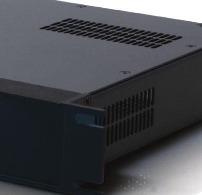
13 Mounting and operating environment Power connection and grounding Auxiliary signals. Linear Time Code input, loudness controls, alarm outputs and DC inputs are grouped together on a single connection. To gain access to any of these, you will need to fabricate a custom connector. Log repository. The Sentinel downloads its measurement data to a log repository. If you are using this data as an archival record, you may need to consider procedures for managing the data. The Sentinel is designed for rack mounting and comes with integral rack ears. The instrument dissipates relatively little heat, 7 Watts for analog input units and under 10 Watts for digital input units. No special cooling is required for operation within the specified temperature range. However, the instrument should always be used indoors in a non-condensing environment. The Sentinel is supplied with a universal input voltage external power supply. It is designed to plug into any standard outlet strip and occupy only one space. This avoids the fit problems typically encountered when attempting to use multiple external supplies in one system. Outside North America, use an appropriate adaptor to fit the mains power outlet. This instrument is not grounded through its power supply. Grounding of the metal enclosure will occur through the equipment rack, audio connections (shield or individual pins) or through the auxiliary signals connector. Do not depend upon or attempt to use the enclosure as a safety ground. A strain relief is provided for the power supply cord to prevent accidental removal of power. After plugging the low voltage power cord into the Sentinel power input connector, loop the cord through the supplied strain relief. Installation 7
14 Network connection User interface configuration and use The Sentinel provides a 10BASE-T Ethernet network interface through an RJ45 connector on the rear panel. By default, the Sentinel determines its TCP/IP network settings using the Dynamic Host Configuration Protocol (DHCP). This requires a DHCP server on your network to supply the settings. Alternatively, you can configure static network settings through the network setup section of the Front Panel menus (p. 19). Static settings are stored in non-volatile RAM, so they are preserved if power is interrupted. The configured IP address (dynamic or static) is shown on the front panel LCD display. The Sentinel provides its user interface through your browser. It is accessible from wherever you have network access to the Sentinel. Connect your browser to the user interface by using the Sentinel s IP address. You'll use the interface to verify the installation, and to perform several configuration steps. Browser compatibility and system requirements The user interface is compatible with these browsers: Chrome Firefox Internet Explorer Safari v6.0 or later v3.5 or later 8 or 9, IE7 Compatibility View off v5.0 or later 8 User Manual Your browser must have cookies enabled for the user interface to operate correctly. The log data features require the Java Runtime Environment, v1.5.x or later, to be installed and enabled in your web browser settings. If the user interface is unresponsive or the displays are fragmented or corrupted, check your browser version and compatibility settings. Indi-
15 cators on the status bar (p. 34) can also help you diagnose user interface problems. The Sentinel user interface performs substantial processing in the browser. Browser performance is continually improving, and you will find the interface is most responsive with the latest browser versions. Similar considerations apply to your choice of workstation or laptop faster, current-generation systems will perform better. Modifying settings AES digital audio connection The user interface is divided into two main pages. The Chapter 4, Readings page (p. 23), initially visible, displays measurement panels. The Settings page (p. 59) displays settings panels, where you can view and modify settings. On the left of each page is a navigation panel that lets you select which information panels are visible, and lets you switch pages. Briefly, to modify settings, you: 1. Switch to the Settings page (click Show Settings in the navigation bar), 2. Unlock the settings (click Modify Settings in the navigation bar, respond to the security prompt with a blank username and your Sentinel s password audio is the default), 3. Select panels and change settings as required, 4. Save changes (click Save Settings in the navigation bar), 5. Return to the Readings page (click Show Readings in the navigation bar). The AES audio module provides two HD15 connectors for audio connections. The AES In jack accepts input from coded audio streams. The AES In/Out jack accepts discrete PCM input channels. Installation 9
16 AES In connection Coded audio input channels, compatible with VGA monitor cable pinout. 1. Input 1 (red). 2. Input 2 (green). 3. Input 3 (blue). 4. Input 4 (h-synch). The AES In jack accepts up to 4 balanced or unbalanced coded audio streams in AES-3 format, any one of which may be routed to the internal Dolby decoder. Unbalanced inputs use standard VGA monitor cables. Balanced operation is selected by shorting a pin on the connector to ground. Qualis Audio provides an optional HD15 to XLR cable for this configuration. Specifications for fabricating custom cabling are provided in AES digital audio connections (p. 84). AES In/Out connection Discrete PCM input channels, compatible with VGA monitor cable pinout. 1. Input 1 (red). 2. Input 2 (green). 3. Input 3 (blue). 4. Input 4 (h-synch). 5. Coded audio output (vsynch). The AES In/Out jack accepts up to 4 balanced or unbalanced AES streams. Each carries 2 channels for a total of 8 input channels. These accept PCM format inputs which may be directly monitored. When the Sentinel is configured to process coded audio input, the AES In/Out connector outputs the selected coded audio signal. This signal is always unbalanced. 10 User Manual
17 SDI digital audio connection SDI SD or HD input stream. The AES audio input/output connection has identical characteristics to the AES input connection, except for the addition of the coded audio output. Specifications for fabricating custom cabling are provided in AES digital audio connections (p. 84). Input-to-channel assignment You assign digital input connections to internal Sentinel channels through the user interface. Select the channel assignments on the Input & Sources settings panel (p. 61) with the Use Input From field. When monitoring PCM inputs in AES-3 format, any channel from the AES In/Out connector can be assigned to any of the internal channels. When monitoring coded audio streams, any channel from the decoder may be routed to any internal channel. The description of the Dolby Metadata panel (p. 54) lists channel orders for common channel configurations. The SDI audio module provides three jacks. There are two BNC connectors for SDI signals. SDI In accepts an SD or HD input, and SDI Thru outputs a reclocked version of this input. AES In/Out, an HD15 connector, accepts discrete PCM input channels. SDI In and Thru connections The SDI Input accepts both SD and HD signals up to 2.97 GB. The receiver automatically locks to the applied input and creates a reclocked version which drives the output. Two groups are extracted from the stream and the resulting 8 channels are available for monitoring as PCM signals. Installation 11
18 Analog audio connection Analog input signals, compatible with TASCAM pinout. The SDI input and reclocked output both use high performance BNC connectors. Particularly when monitoring HD-SDI signals it is essential to use high quality 75 Ω BNC cables. AES In/Out connection The AES in/out connector on the SDI audio module functions identically to the AES in/out connector on the AES audio module. Input-to-channel assignment You assign digital input connections to internal Sentinel channels through the user interface. Select the channel assignments on the Input & Sources settings panel (p. 61) with the Use Input From field. When monitoring PCM inputs in SDI format, two groups of the available 4 may be monitored. These 8 channels can be assigned to any of the internal channels. When monitoring coded audio streams, any channel from the decoder may be routed to any internal channel. The description of the Dolby Metadata panel (p. 54) lists channel orders for common channel configurations. The analog input accepts up to 8 channels of balanced or unbalanced analog audio. The input impedance is 1 MΩ, allowing minimal loading in bridged applications and making the input CMRR immune to typ- 12 User Manual
19 ical source impedance imbalance. A common mode filter is used to improve RF immunity. The high input impedance of the Sentinel makes unconnected inputs sensitive to noise and AC fields. These can cause low-level bargraph activity. Unused inputs should be shorted or resistively terminated with a low value. Connecting balanced inputs Commercial breakout cables may be used to connect the Sentinel input to XLR or ¼" phone jacks. Cables should follow the standard pin 2 high, pin 3 low and pin 1 shield connection on the female XLR connectors. These are available from a variety of vendors in a range of lengths: Apogee-AD-8-IFC Horizon DA88-*F HOSA DTF-80* Mogami-DB25-XLRF- Monster SLDA88-FX-* Planet Waves XLR-F Pro Co DA88XF* Quantum Audio QDA88-*F Switchcraft DB25M*XLRF 1 m 5, 15 ft 3, 5 m 5, 10, 15, 20, 25 ft 1.5, 3, 5 m 5, 10, 25 ft 5, 10, 15 ft 6, 15, 20, 25 ft 2, 3, 5 ft Specifications for fabricating custom cabling are provided in Analog audio connections (p. 85). Connecting unbalanced inputs Commercial breakout cables are also available to connect the Sentinel input to RCA connectors or other unbalanced sources. However, take care to ensure the cable connects the low side of the input to the source connector shield at the source itself. Otherwise the differential input will be unable to attenuate hum induced by ground potential differences between the source and the Sentinel. Specifications for fabricating custom cabling are provided in Analog audio connections (p. 85). Installation 13
20 Auxiliary signals connection Analog levels configuration The maximum input level is software selectable between +28 and +22 dbu by using the Max Analog In field of the Levels & Metering settings panel (p. 62). The lower maximum level setting provides a correspondingly lower noise floor and maintains dynamic range in installations with lower operating levels. The range of settings available for Clip Level, Overload Level and Alignment Level are all affected by the Max Analog In setting. Input-to-channel assignment You assign analog input connections to internal Sentinel channels through the user interface. Select the channel assignments on the Input & Sources settings panel (p. 61) with the Use Input From field. Any input connection can be assigned to any of the internal channels. The auxiliary signals connection combines the Linear Time Code (LTC) input, loudness meter controls, alarm outputs, and DC inputs. There are two pairs of loudness meter controls: one for the Surround loudness meter, and a second for the Ancillary loudness meter. One input of each pair switches between active measurement and the paused state, or between measuring program and measuring commercial. The other input completes the current measurement and begins a new measurement. The four alarm outputs are asserted when the corresponding alarms occur. The six DC inputs may be used to measure DC voltages, and by appropriate setting of the input comparison thresholds they may be used to monitor low speed logic signals. Specifications for fabricating custom cabling are provided in Auxiliary connections (p. 86). 14 User Manual
21 Date & time configuration Log repository configuration DC input threshholds configuration Error threshholds can be set for the DC inputs in the DC Inputs & Temperature settings panel (p. 70). The Sentinel uses a real-time clock to accurately record the timing of measurements in Coordinated Universal Time (UTC). For it to be able to store measurement data for later retrieval, it is essential that the clock be set accurately. The Sentinel ships with its clock already set. To maintain accuracy, it synchronizes the clock to a Network Time Protocol (NTP) server. When times are displayed, they are converted to the local timezone and daylight savings setting. You configure the NTP service and local timezone through the Date & Time settings panel (p. 73). The timezone can also be set through the Front Panel menus (p. 19), and you can manually set the clock through the menus if, for some reason, you're not able to use an NTP server. The Sentinel logs all sampled audio characteristics and all measurements. It stores up to 25 hours of this data internally. However, measurement data is stored in volatile memory and will be lost in the event of a power failure. To preserve and access the data, it must be downloaded from the Sentinel to a storage repository. Once data is in the repository, it is protected from loss, and you can use the user interface to review and display it in the same way as live readings. The Sentinel stores the log repository in a local directory on your system, or a directory on a shared network filesystem. The simplest way to create and update the repository is to let the user interface do it from your browser. You need to do this to ensure the user interface has access to all logged readings. Installation 15
22 In a production environment, where the Sentinel is in operation continuously, you will also need to set up scheduled downloading, so you are not depending on the user interface to keep the repository up to date. In the user interface, configuration options for defining the log repository and scheduling downloads are located in the pulldown menu on the readings navigation panel (at the left of the readings page). Create a log repository using the Select Repository... option, and set Scheduled Log Save to Continuous to to let the user interface store data in the repository. Chapter 6, Log Repository (p. 75) provides additional information. In particular, it describes how to schedule the downloading of log data separately from the user interface. 16 User Manual
23 3 Front Panel Front panel displays and controls 18 Front Panel menus 19 17
24 Front panel displays and controls The Qualis Audio Sentinel is intended to be controlled over a network connection from a standard Javascript enabled browser. However, some of the settings are only accessible from the front panel, principally those relating to network operation. All settings affecting instrument operation, alarming and reporting are stored in non-volatile RAM to ensure proper operation after power failure. Buttons and knob are used to navigate the configuration menus and change settings. Backlit labels identify control s function and operability lit when functional, off when inoperative. 1. LCD display. During operation, shows date and time, and IP address. On input, line 1 shows selection title, line 2 shows setting. 2. Up/Down. Scroll through choices in current line 2 list. 3. Left/Right. Step through values or fields of current line 2 setting active value is underlined. 4. Select. Enters configuration menus, confirms setting of current selection. 5. Back. Moves back in menu hierarchy. Discards setting unless SELECT is pressed first. 6. Knob. Rotate to change active setting value or field. Press to confirm setting of current selection. 7. Mute. Silences audible alarm. 8. Alarm. Lights when one or more alarms are active, cycles through numbers of active alarms. 18 User Manual
25 Front Panel menus Date & time setup These menu items set the Sentinel s real-time clock, the date and time formats for the front panel display, timezone, and daylight savings time. The Sentinel does not automatically switch to or from daylight savings. As an alternative to setting the date and time manually, the Sentinel can also be synchronized to a Network Time Protocol (NTP) server. The NTP service is configured from the user interface, using the Date & Time set- Front Panel 19
26 20 User Manual tings panel (p. 73). This setup panel also lets you set the date and time formats, timezone, and daylight savings time. Network setup These menu items let you allow the Sentinel to determine its TCP/IP network settings automatically using DHCP services, or to configure it with static settings. There are also menu items to display the network settings in use, and the Sentinel s Ethernet MAC address. By default, the Sentinel will use DHCP for network settings. When entering an IP address, use the left/right buttons to select an octet and use the knob to scroll through values. Password setup The web access password must be entered from the user interface in order to change Sentinel configuration settings. Up to fifteen characters can be entered. The default password is audio. Use the knob to scroll through characters. Entering the character truncates the password string without having to set subsequent characters to blanks. Device name setup The device name is used in alarm messages to identify the Sentinel from which the alarm originated. It may also be set from the user interface, using the Alarm Actions settings panel (p. 72). Use the knob to scroll through characters. Entering the character truncates the password string without having to set subsequent characters to blanks. Firmware revision display Displays revision dates for the field-upgradeable ROMs in the Sentinel. Dates are in mm/dd/yy format (month, day, year).
27 There are separate listings for the two digital input module ROM slots, M1 and M2. Only occupied slots are listed. LCD contrast setup Adjusts the LCD contrast on the front panel. Use the knob to scroll through values. Front Panel 21
28 22
29 4 Readings page Meters panel 25 Bargraph meters 26 Balance display 30 Spectrum and downmix compatibility displays 31 Status bar 34 Loudness meter panel 34 Hardware loudness gating control 39 Loudness gating control buttons 39 Readings Timeline panel 40 Timeline 40 Timeline scroll bar 43 Transport control buttons 43 Segment table 45 Signal Histogram panel 47 Errors panel 48 Digital Interface panel 51 Dolby Metadata panel 54 DC Inputs & Temperature panel 58 23
30 On the left of the Readings page is a navigation panel that lets you select which measurement panels are visible. It also lets you switch to the Settings page (p. 59). Initially, only the main metering panel will be visible. The panels you ve selected for display are tracked from one session to the next, as are settings made through the configuration menus associated with the readings panels. These preferences are all associated with your browser other users accessing the same Sentinel can set their own preferences. The web interface saves preferences in your browser s local storage. You'll need to reenter the settings if they're lost for some reason if you clear cookies on your browser, change browsers, or change the IP address of the Sentinel. Meters panel (p. 25) true peak meters (p. 28) bargraph meters (p. 26) balance display (p. 30) spectrum and downmix compatibility displays (p. 31) status bar (p. 34) Loudness meter panel (p. 34) Bargraph display of continuous and integrated loudness measurements. Readings Timeline panel (p. 40) Timeline traces of recorded readings. Allows you to review and replay readings recorded by the Sentinel. Errors panel (p. 48)Error and alarm state for all eight inputs, downmixes, auxiliary inputs. Digital Interface panel (p. 51) Interface characteristics and metadata for AES or SDI input. Dolby Metadata panel (p. 54) Metadata for Dolby coded audio. DC Inputs & Temperature panel (p. 58) Auxiliary input DC Voltage readings and Sentinel internal temperature. 24 User Manual

31 Signal Histogram panel (p. 47) Summary graphical display of selected ranges from recorded readings. Settings page (p. 59) Panels for configuring Sentinel measurements and error reporting. Meters panel 1. Input channel bargraph meters. True peak indicator, level bar and bandwidth bar for each input channel. 2. Balance display. Plan view of listening space with listener at center. 3. Spectrum display. 4. Downmix compatibility display. Power loss in stereo and mono downmix by octave. 5. Downmix bargraph meters. True peak indicator and level bar for downmix channels. 6. Status bar. Status indicators, serial number, date & time, linear time code. Readings page 25
 and one for a set of downmixes created by the Sentinel (on the right).")
32 Bargraph meters 1. Meter axis. Meter units at top, meter type at bottom. 2. True peak. Indicator bar and numeric value. 3. Level bar. 4. Channel. 5. Bandwidth bar. The Meters panel includes two groups of vertical bargraphs, one for the input channels (on the left) and one for a set of downmixes created by the Sentinel (on the right). Both sets of bargraphs include numeric displays which show the true peak level of that channel. The input channel bargraphs also include indicators which show the approximate signal bandwidth for each channel. Input channels The Sentinel accepts up to 8 input channels. Six, seven or all eight input channels may be grouped into a surround program. The remaining channels, if any, are treated as a second program called the Ancillary Program. The surround format, as set in the Input & Sources settings panel (p. 61), determines the channels for which bar meters are displayed. The configuration pulldown menu for the Meters panel allows you to change the Channel Order of the bar meters. Downmix channels The internal downmix channels are created from the input signals as: Lo Ro sums LF, CF, LS and LB (or CB in 6.1 mode), if present. sums RF, CF, RS and RB (or CB in 6.1 mode), if present. 26 User Manual
33 M sums Lo and Ro. The gain coefficients applied to the center, front, surround and back channels when summing into the Lo and Ro downmix are selectable. They are set in the Downmix Compatibility settings panel (p. 68). These downmix gains are also used when performing the Compatibility measurements. After summing, normalization factors are applied so the peak amplitude of the downmixed channels will not exceed full scale. If digital inputs are used, the gain coefficients may be automatically set using information contained in the metadata, if present. If automatic setting is selected and the metadata downmix coefficients are set to Not Indicated or if the metadata is missing, the manually set values will be used. Bargraph ballistics The input and downmix channel bargraph levels are measured with user selected metering ballistics. The Meter Type in use sets the displayed scale and units. See Levels & Metering settings panel (p. 62) for descriptions of meter types. Display colors As is common for bargraph level meters, the indicator color changes with level. From top to bottom: Red Yellow Green Signal is at or above Overload level Signal is above Alignment Level and below Overload Level Signal is below Alignment Level The Alignment, Overload and Clipping Levels are set in the Levels & Metering settings panel (p. 62). For most meter types these parameters are defined in the appropriate standards document. In all cases these standards based values may be overridden with user selected values. Readings page 27
34 Warning Messages A red vertically-written error message appears over the bargraph if certain errors are detected in that channel. They are not displayed for downmix channels. When multiple errors are present, the highest priority error is displayed. The possible errors, from highest to lowest priority, are: PARITY (digital input only) BIPHASE (digital input only) UNLOCK (digital input only) VALID (digital input only) CLIP (digital input only) REPEAT Digital input samples repeated the same value. CLIP True peak exceeds clipping level set in the Levels & Metering settings panel (p. 62). OVER Metered level (bargraph) exceeds overload level set in the Levels & Metering settings panel (p. 62). UNDER Loudness less than threshold set in the Loudness settings panel (p. 64). HUM Line frequency components above threshold set in the Channel Analysis settings panel (p. 67). These errors are also reported in the Errors panel (p. 48), where it is possible to simultaneously view all errors, regardless of priority. True peak meters The numeric displays above the input and downmix channel bargraphs are true peak meters. True peak meters interpolate the amplitude between samples for a more accurate reading of level. Rather than display the peak sample value, True-Peak meters display the amplitude which will result when the signal is converted to analog form. The units are in db relative to the maximum input level. With Analog inputs this is either +28 or +22 dbu as set in Levels & Metering settings panel (p. 62). With a digital source dbfs units are used. No meter ballistic is applied. 28 User Manual

35 True peak readings which reach the user defined clip level will produce a CLIP indication on the bar meter of the corresponding input channel. The configuration pulldown menu for the Meters panel allows you to set the Peak Hold Time from 1 to 30 seconds. Bandwidth indicators The input channel bargraphs have a graphic below the channel label which gives an approximate indication of signal bandwidth. This allows a quick assessment of which channels are dominated by dialog and which have extensive music or effects content. The left edge of the graphic is controlled by the low frequency signal content. The right edge of the graphic is dependent on the high frequency signal content. The color also changes with the low and high frequency energy, giving two equivalent methods of interpreting the information. Configuration Channel Order selects the order of channels in the multichannel meter display. The Surround Format setting (set in the Input & Sources settings panel (p. 61)) constrains which channels are actually displayed. If the Surround Format is 5.1, LB and RB are not shown; for 6.1, LB is replaced by CB and RB is not shown; for 5.1+2, ancillary channels A1 and A2 replace LB and RB; for 6.1+1, CB replaces LB and ancillary channel A1 replaces RB. Peak Hold Time sets the time for which the graphical peak level indicators on the bargraphs display a recent maximum. It does not the affect the True Peak meter numeric displays. The hold time may be set to 1, 3, 10 or 30 seconds. Readings page 29

36 Balance display The balance display is a plan view of the listening space with listener at center surrounded by loudspeakers; the LFE channel is an additional loudspeaker to the right. Ancillary channels are not included. left: 7.1 format, middle: 6.1 or 6.1+2, right: 5.1 or The brightness of the loudspeaker icons on the balance display changes in proportion to the relative loudness of the audio signals on their respective channels, with the loudest channel brightest. This creates an intuitive view of the sound space balance. For example, a phantom monaural sound appears as equal brightness in both the left and right front speaker icons. The loudness computations used to drive the balance display are shared with the program loudness measurement. Consequently, the surround channel balance display is frequency weighted according to the same ITU standard. However, the LFE channel icon is driven from an unweighted loudness computation with its gain adjusted for accurate relative loudness assessment. As per international standards, the LFE is not included in the overall loudness measurement. 30 User Manual
 in octave bands. 3. LFE compatibility display.")
37 Spectrum and downmix compatibility displays 1. Spectrum display. Shows the spectrum of the mono downmix channel in octave bands. 2. Downmix compatibility display. Shows stereo and monaural downmix compatibility (power loss compared to original) in octave bands. 3. LFE compatibility display. Spectrum display The spectrum display shows the surround program spectrum in octave spaced band-center frequency values. The display is updated at and averaged over 0.68 second intervals. This display has several important applications: It allows verification that the signal spectrum is consistent with the type of program being monitored. For example, there should not be significant high or low frequency content in a program that is supposed to be dominantly dialog. It enables assessment of the relative level of spectral components which are experiencing downmix cancellation. If the downmix compatibility display shows significant cancellation at 4 khz but the 4 khz octave band is 20 db below the 1 khz octave, the cancellation is likely to be unimportant. However, if the dominant spectral components are also the ones showing cancellation then a smaller degree of cancellation may be cause for concern. Downmix compatibility display The downmix compatibility display shows stereo and monaural downmix compatibility in octave spaced band-center frequency values. Octave band power measurements are made for each input channel and each of the downmix channels. The input channel measurements Readings page 31
38 used for a specific downmix are summed and compared to a downmix channel measurement. The loss in each octave is displayed in a manner similar to a frequency response graph where the rolloff represents the signal loss at each octave band. There are separate indicators for left and right stereo channels and monaural: Monaural downmix loss. Left stereo downmix loss. Right stereo downmix loss. As these go down, away from the 0 db line, it means that the signal has cancelled more completely and more is missing from the mono or stereo mix. The display changes color as the loss increases: green when there is little loss, yellow when loss is within 3db of the downmix error threshhold, red when it equals or exceeds the threshhold. The downmix error threshhold is set in the Downmix Compatibility settings panel (p. 68). Downmix compatibility calculations in detail The Sentinel takes a radically different approach to quantifying compatibility from that used in other products. Other products characterize interchannel phase relationships and show these to the user as multidimensional Lissajous patterns. They typically produce complex multicolor shapes which must be studied and require much experience to correctly interpret. Instead, the Sentinel measures the program channels to approximately 1/30th octave resolution. It also performs downmixing and measures the downmix channels in the identical manner. The frequency domain power measurements of the individual channels are summed and compared to the frequency domain power of the downmix channels. They should be equal. However, if there are cancellations in the stereo or mono downmix signals their power will be reduced. This reduction is exactly the amount of signal which will be missing from the program 32 User Manual
39 heard by stereo or mono listeners. The result is a direct assessment of the change in the program experienced by these listeners. The internal Downmix channels are created from the input signals as follows: Lo Ro M Sums LF, CF, LS and LB (or CB in 6.1 mode), if present. Sums RF, CF, RS and RB (or CB in 6.1 mode), if present. Summed from Lo and Ro. The Lo and Ro downmix attenuation values for center, surround and back-surround are set in the Downmix Compatibility settings panel (p. 68). Frequency range filters The frequency at which cancellations occur is important when assessing the severity of a compatibility problem. Cancellations in the voice band are generally of the highest concern because of their potential effect on intelligibility. Downmix problems at low or high frequencies, though potentially of concern, cause changes in effects or ambience and are generally less problematic. The horizontally arranged frequency domain view makes such distinctions immediately evident. Calculation of losses by frequency also simplifies application of error conditions to the data. The Downmix Compatibility settings panel (p. 68) provides settings that control what downmix measurements consititute an error. Comparisons may be limited at both high and low frequencies and the amount of loss considered acceptable may all be set, along with a minimum time that the error must persist before being reported. Readings page 33

40 Status bar The status bar displays health and activity status indicators, Sentinel identification, current time. 1. Network status icon. 2. Log repository status icon. 3. Serial number. 4. Real-time clock date, time, timezone and status icon. 5. Linear time code and status icon. Loudness meter panel Status icons are green (or hidden) when there are no problems, yellow to indicate a warning, and red to indicate more serious conditions. If you move the cursor over a status icon, a detailed description of the status condition will be displayed. The log repository status icon is animated with a moving dot when data is being downloaded from the Sentinel to the repository. When the user interface is displaying live readings, the displayed time and linear time code are the latest values reported by the Sentinel. When paused or displaying logged data, they are recorded values that indicate the time at which the displayed measurements were taken. See the Readings Timeline panel (p. 40) for more details. Left meter bar displays loudness measurements continuously updated from the audio signal. 1. Short-Term loudness. 2. Loudness reference level. 3. Momentary loudness. Right meter bar displays integrated measurements computed across an extended time segment. 1. Integrated loudness. 2. Maximum momentary loudness. 3. Loudness range. 4. Loudness integration indicator. 5. Maximum true peak. 6. Integration restart button. 7. Program/commercial segment select button. 34 User Manual
41 The loudness meter panel is organized around a pair of meter bars: continuously updated measurements (continuous readings) on the left, those computed across a specific time segment of the audio signal (integrated readings) on the right. The measurement gating for the integrated readings may be controlled by hardware signals applied to the rear panel auxiliary signals connector or by software control through the buttons at the bottom of the loudness meter panel. The selection of hardware or software control is made in the Loudness settings panel (p. 64). Continuous loudness measurements The continuous measurements are the Momentary Loudness (ML) and Short-Term Loudness (SL). The momentary loudness is displayed as a bar and updated 10 times per second. The short-term loudness is displayed graphically as a line on the left bargraph and numerically above it. The short-term loudness is compared to a user-defined threshold, displayed on the bargraph as a thin red line. When this threshold is exceeded for a user-specified duration an error is generated. When this error condition exists, both the graphical and numeric short-term loudness displays will be red. If the loudness remains below threshold the displays will be green. This threshold is set relative to the Target loudness value in the Loudness settings panel (p. 64). The short-term loudness corresponds to a listeners perception of program loudness. The ability to set an upper limit on this measurement allows an early warning of listener dissatisfaction with loudness control. The short-term loudness is also displayed graphically on the Readings Timeline panel (p. 40). Integrated loudness measurements The right-hand meter bar displays cumulative loudness readings. The displayed readings depend on which loudness standard is configured. The display provides an indicator (a bar) for an integrated loudness Readings page 35
42 level, an indicator (a little dot) for a maximum loudness level, and a pane that shows the loudness range. The background of the bar shows the loudness error range, as configured in the Loudness settings panel (p. 64). The numeric accumulated loudness value is displayed above the bar. Numeric values for maximum loudness and range, if defined, are displayed below the bar. Integrated loudness measurements require a minimum segment length of 3.2 seconds. Loudness integration status indicator The loudness integration status indicator shows the state of integrated loudness measurements: Loudness calculation in progress (animated). Loudness calculation paused. Final values, loudness is within specified tolerance. Final values, loudness is outside specified tolerance. Conventional and Dual Stream loudness measurements The Sentinel can measure integrated loudness exactly as specified in the ITU BS1770 standard. The standard, along with the ATSC and EBU variants, requires the ability to run, pause, stop and reset the loudness measurement. The Sentinel rear panel auxiliary signals connector provides two GPI pins for this purpose. One serves as a RUN/PAUSE control and the other as a RESET control over the measurement. There are also equivalent soft buttons on the UI and network accessible software commands for the same functions. The conventional mode of operation specified in these standards was developed with measuring a single program or commercial being produced or broadcast. The pause feature allows the portions of a program during commercial or other break periods to be ignored and an accurate measurement of the program obtained. 36 User Manual
43 In a broadcast stream there is no pause. When a program is paused the time is occupied by a commercial or other interstitial content. The loudness of these interleaved segments is just as important, possibly more so, as the program. However, the way the loudness measurements are defined it is not possible to measure the individual pieces of a program separately, the measurement must be paused and measurement must resume when the break is over. Therefore to measure both the program and the commercial loudness independently requires two loudness meters, one for the program and one for the commercials. The control lines for these two meters must be interconnected so that they operate synchronously. Dual Stream loudness measurement is Qualis Audio s patent pending solution to this problem. The Sentinel is designed to handle a program stream with interleaved commercial segments. When the instrument is told that the program being monitored has gone to commercial it pauses the program measurement. However, it continues measuring and allocates the measured energy to a separate results buffer for the commercial. When the instrument receives a reset command it finalizes the readings and begins measuring another commercial. If instead it is told that the stream has returned to the original program it finalizes the commercial loudness reading and resumes measuring the program exactly as a conventional meter coming out of pause would do. When the program is complete, assertion of the reset command will finalize the program measurement and the instrument will immediately begin making a new measurement of program loudness. These program and commercial loudness measurements are displayed, logged and reported, along with the program/commercial identifier, the time and the timecode. Each measurement is compared to the specified loudness limits and alarms are issued if required. Readings page 37

44 Configuration Meter Scale sets the scale used to display the loudness measurement bargraphs, and selects between relative and absolute display units. The bargraph scale may be set to either of the EBU required ranges of 27 or 54 LU, or a 75 LU range. The larger ranges allow monitoring of wider dynamic range material at the expense of display resolution. The 27 and 54 LU EBU meter ranges are positioned relative to the loudness reference, with 1/3rd of the scale above the reference and 2/3rds below. The reference may be a fixed target value, or the dialnorm value from the Dolby metadata. The reference selection is set in the Loudness settings panel (p. 64). The 75 LU meter range has its maximum at 0 LKFS. The numeric loudness values may be displayed in either relative or absolute units. (Except loudness range, which by definition is a relative value.) The relative display shows measurements in loudness units (LU) relative to the loudness reference. Result Hold Time sets the time for which the panel displays the results of completed integrated loudness calculations. The hold time may be set to 1, 3, 10 or 30 seconds. The integrated loudness, loudness range, maximum momentary loudness and the maximum true-peak amplitude are all measured during a defined time period, with definite beginning and end events. Although the measurements are updated in real time, they are not final until the end time is reached. In a real time measurement application, another measurement follows immediately after a completed measurement. The hold time gives an operator a chance to read the values before they disappear and a new measurement begins. 38 User Manual
45 Hardware loudness gating control In the Dual Stream measurement mode there are still just two control signals: one to select the measurement context (called P/C), and one to reset the meter (called RESET). The same control line is used for RUN/ PAUSE and for P/C, its function changes with the mode. The polarity of each control line is defined on the Loudness settings panel (p. 64). This is also where the selection of conventional or Dual Stream mode is made, along with selection of hardware or software control. In Dual Stream mode there is interaction between the P/C control line and the RESET control line. A Reset event finalizes an Integrated Loudness measurement, and starts a new measurement. An explicit Reset event occurs whenever the RESET control line transitions from False to True. An implicit Reset event occurs under the following conditions: 1) A Reset of a Commercial segment occurs when the P/C control line makes a transition from the Commercial state to the Program state. 2) A Reset of a Program segment occurs when the P/C control line makes a transition to the Program state, while the RESET control line is True. The loudness control lines must be asserted for a minimum width of 40 ms and are debounced for 20 ms following the last transition. The polarity of each control line can be defined in the Loudness settings panel (p. 64). Loudness gating control buttons Located at the bottom of the loudness meter panel, the loudness gating control buttons let you control integrated loudness measurement. Program/Commercial button Slider that switches between program and commercial segment measurement. Button appearance alternates between program (P) and commercial (C) graphics. Measure/Pause button Pauses or resumes measurement. Button appearance alternates between measure and pause graphics. This button replaces the program/commercial button when the Sentinel is in measure/pause mode. Readings page 39

46 Restart button Restarts loudness measurement. Readings Timeline panel 1. Readings timeline. Loudness, program/commercial, error/alarm traces shown. 2. Programming segment table. 3. Timeline scroll bar. 4. Play/Pause button. 5. Skip backward button. 6. Skip forward button. 40 User Manual The Readings Timeline panel is a summary display of the history of readings from the Sentinel, from the latest readings back through the stored log data. The timeline panel also allows you to identify and work with programming segments within the readings history. The two major components of the panel are the timeline itself, which displays a set of signal traces, and the segment table. The web interface saves a temporary record of readings as it receives them from the Sentinel. These readings, combined with readings downloaded and saved in the Chapter 6, Log Repository (p. 75), provide a continuous record, limited only by your retention period for the log repository. Timeline What is visible on the timeline display is typically only a portion of the history. When the user interface is displaying live data, the timeline displays the most recent readings, the right end of the display tracks the current time, and older readings move off the left end. When browsing or replaying logged readings, the timeline display can be moved through the range of logged data.
.")
47 Signal traces The timeline displays your choice of Program Loudness and Maximum Downmix measurement traces. The loudness trace displays short-term loudness. The downmix trace displays the maximum of left and right downmix values within the frequency range configured in the Downmix Compatibility settings panel (p. 68). A programming segment trace appears below these traces. It shows the breakdown of the readings into programming segments for integrated loudness measurements. The lower half of the trace indicates program segment measurements; it's shadowed wherever the measurement was paused. The upper half indicates commercial segments. Breaks in the traces mark the positions where measurements were reset. A summary trace of error and alarms is also always visible as the last trace. It shows a yellow marker at each reading that records an error. If the error resulted in an alarm, a red marker appears above the yellow. Cursors 1. Current position cursor. Appearance changes to indicate play/paused state (paused shown). 2. Left bound cursor. 3. Right bound cursor. 4. Right position flag (appears when cursor is dragged). Trace cursors consist of a single current position cursor, which is always present, and zero or more pairs of segment bounds cursors. Current Position cursor Displays the current play position. When the cursor is positioned at the current time, the display shows live readings and the cursor position advances automatically. Dragging the cursor away from current time changes to paused state, freezing the motion of the meter and timeline displays. Dragging when replaying saved readings changes the replay position, and replay continues when the cursor is released. Readings page 41
48 42 User Manual The readings at the current position are displayed on the meters and secondary readings panels. When displaying live data, these are current readings as they are received from the Sentinel; at other positions in the timeline, saved readings are displayed. When dragging the current position, the readings update as the cursor moves. The current position cursor always stays within the visible portion of the timeline display. When repositioning of the display would move the cursor out of view, it sticks at the end of the displayed range that is, it moves to the position within the display area that is closest to its prior position. This can have the side-effect of pausing the display. (To resume showing live readings, you can press the Skip Forward button to advance the position to the current time.) Segment bounds cursor pairs Segment bound cursor pairs indicate the bounds of programming segments. Each pair corresponds to an entry in the segment table. Both bounds cursors display the segment number, which also appears on the segment table entry. Bounds cursor pairs are created and deleted as segments are added and removed from the segment table, using the segment add/remove buttons provided by the segment table (p. 45). You can also remove a pair (and its associated segment) by dragging either cursor off the timeline vertically. Dragging the left bound of a pair moves both cursors, maintaining their separation. Dragging the right bound does not move the left. In other words, you position a segment by dragging its left bound, and change its duration by dragging its right bound. Bounds cursors move independently when dragged, except that neither cursor can be dragged past the other, and instead pulls the other cursor along with it. The cursors are adjacent when a new segment is created you can separate them by dragging one back and forth. Dragging when playing logged readings changes to paused state. Dragging while playing live readings does not change state, and live play resumes when dragging stops.
49 Configuration Timeline Traces selects the data traces displayed on the timeline. It allows a choice of Program Loudness and Maximum Downmix measurement traces. Playback Speed selects rate at which readings are displayed during playback. Timeline Scale lets you view the timeline at varying levels of detail from 1:1, where each mark on the timeline represents a single reading, to 1:16, where each mark combines 16 readings. Timeline Range restricts the range of the timeline scroller bar to the last day of data, 7 days, or 30 days. Timeline scroll bar The timeline scroll bar and its scroller, below the timeline traces, indicate the position the visible timeline segment within the readings history, and allow you to reposition the segment of readings data displayed on the timeline. By default, the scroll bar spans your full readings history, but, for convenience, you can restrict its range to 1, 7, or 30 days (see below). Dragging the scroller moves the timeline display. Clicking at a position on the scroll bar moves the timeline toward that position. You can also move the timeline using mouse scroll wheel movements or touch gestures on the scroll bar or timeline itself, if your system support them. Transport control buttons Located in a cluster at the right of the timeline panel, the transport control buttons let you control the play of live or logged readings. Readings page 43
50 Play/Pause button If paused, starts play; if playing live or logged readings, pauses play. Button appearance alternates between play and pause graphics.if play is started within a defined programming segment, it begins at the beginning of the segment. Skip backward button Moves current position to closest preceding beginning segment bound. (If the current position is at a beginning bound, moves to the previous one; does nothing if no bound precedes the current position.) If clicked while displaying live or logged readings, it pauses the display. Skip forward button Moves current position to closest following beginning segment bound. (If the current position is at a beginning bound, moves to the next one.) If no bound follows the current position, it moves to the current time and resumes play of live readings. Replaying of logged readings continues until it reaches a segment bound or the current time. If replay reaches the current time, it then switches to displaying live readings. If it reaches a segment bound, it pauses. Pressing the play button will cause play to restart at the beginning of the segment. In effect, there are two patterns for playing logged readings. You can repeatedly play a defined programming segment. Or you can work without setting up segments, moving the current position and starting and stopping play directly. 44 User Manual

51 Segment table A segment is an interval of time within the Sentinel s readings history. Measured segments are created in real time by the Sentinel; defined segments are created retrospectively through the user interface. The segment table displays all defined segments, and a selection of measured segments centered on the current timeline position. 1. Selected defined segment. Clicking arrow positions timeline to segment. 2. Summary. Combined integrated measurements for defined segments. 3. Segment add/remove buttons. Define new segment or delete selected segment. 4. Segment status. Calculation status for measured segment, index number for defined segments. 5. Segment category. Program/commercial for measured segment, Include/exclude/ignore for defined segment. 6. Begin/End times. Editable for defined segment. 7. Duration. Editable for defined segment. 8. Begin LTC. 9. Integrated measurements. Loudness, maximum true peak, loudness range. Segments specified intervals of time within the Sentinel s readings history are of two kinds, measured segments and defined segments. The segment table displays both types of segments in chronological order. Measured segments Measured segments are created in real time by hardware or software inputs to the Sentinel. The associated loudness measurements are generated by the hardware and displayed on the loudness meter panel as they occur. These measurements, their beginning and ending times, along with their context (program or commercial) are stored in the log data. The segment category setting for a measured segment is either: Program segment. Commercial segment. Readings page 45
52 Defined segments You create defined segments through the user interface. Loudness measurements for defined segments are calculated within the user interface from saved log data and are recalculated when the segment s bounds change, so they update in real time. Each has a corresponding pair of bounds cursors displayed on the readings timeline. You can change a segment s beginning and ending times by moving its bounds cursors or by editing the begin time, end time or duration displayed on its segment table entry. Defined segments may also appear on the Signal Histogram panel (p. 47). Defined segments are numbered for identification. These numbers are displayed both in the segment table and on the segment s bounds cursors. Numbers are assigned consecutively, starting at one. Adding or deleting segments can cause renumbering. Changing a segment s beginning or ending time can change its position in the table, which can also cause renumbering. Combined measurements for defined segments are displayed as a final entry in the segment table. The segment category setting for a defined segment specifies how the segment contributes to these summary measurements: Add to summary. Exclude from surrounding segment. Ignore. 46 User Manual
.")
53 Signal Histogram panel 1. Y axis. Units are percentages. 2. X axis. Units are fullscale loudness. 3. Histogram traces. 4. Segment key. The Signal Histogram panel summarizes loudness measurements for programming segments selected using the Readings Timeline panel (p. 40). The display updates as you add or remove segments from the timeline, or adjust their limits. Bars of the histogram represent the proportion of readings in 1 db intervals, arranged along the X axis of the histogram from lowest measured loudness to highest. The height of a bar is the percentage of the readings in its interval. Readings page 47

54 Errors panel The Errors panel provides a concise view of all potential errors measured by the Sentinel. Unlike the warnings overlaid on the bargraphs, there is no prioritization applied to the error summary. These are the icons used to indicate error conditions: No active error. Active error. Recent error. Hold time set in the configuration pulldown menu for the Errors Panel. Channel Errors The Channel Errors section displays a matrix of per-channel errors. There is a column for each channel in the configured surround format and a row for each error. The displayed errors and their sources are: Clip The true peak level is above the User Clip Level. The User Clip Level is set in the Levels & Metering settings panel (p. 62). Over The metered level is above the Overload Level. The Overload Level is set in the Levels & Metering settings panel (p. 62). Under The loudness is below the allowed threshhold. The Threshold is set in the Loudness settings panel (p. 64). Hum There is an AC mains frequency component present. The threshold is set in the Channel Analysis settings panel (p. 67). Bandwidth The LFE channel bandwidth exceeds the maximum. The maximum is set in the Channel Analysis settings panel (p. 67). Repeat The audio stream repeats a constant value across consecutive samples. The repeat threshhold is set in the Channel Analysis settings panel (p. 67). Valid The validity error flag is asserted. 48 User Manual
55 Interchannel Errors The Interchannel Errors section displays errors which involve multiple channels. These errors and their sources are: Loudness Errors are displayed for short-term and integrated loudness measurements. The short-term loudness error is asserted when the short-term loudness differs from the loudness target by a specified tolerance and duration as set in the Loudness settings panel (p. 64). The integrated loudness error is asserted when the integrated loudness differs from the loudness target by a tolerance specified in the Loudness settings panel (p. 64). Downmix Errors are asserted when any of the downmix compatibility measurements within a specified range of octave bands exceed a threshhold and duration as set in the Downmix Compatibility settings panel (p. 68). L Cancellations on Lo (Left) channel exceed the limits R Cancellations on Ro (Right) channel exceed the limits M Cancellations in Monaural format exceed the limits LFE Cancellations on LFE channel exceed the limits Swap Errors are asserted when there is a suspected interchange of channels, persisting longer than a duration as set in the Channel Analysis settings panel (p. 67). CF-LFE Probable swap of CF (center front) and LFE channels. Asserted if the LFE bandwidth exceeds the CF bandwidth. F-S Probable swap of front (LF and RF) and surround channels (LS and RS). Asserted if the surround loudness exceeds the front. F-B Probable swap of front (LF and RF) and back channels (LB and RB) in 7.1 mode. Asserted if the back loudness exceeds the front. Readings page 49
56 Digital Errors The Digital Errors section displays errors involving the digital input channels and digital metadata. Digital In Columns 1-4 show the receiver lock status for each of the four 2-channel PCM inputs. Column 5 shows the receiver lock status for coded audio. Interchannel Errors The sample rate and word width (number of active bits) are measured for each channel of the surround program, and the values are checked for differences between channels. Auxiliary I/O Channel metadata is extracted and checked for differences in similar fashion. This metadata is also checked for differences with measured values for each channel. The differences are displayed in tabular format, with columns for sample rate and word width. There are rows for differences between measured values, and between measured and metadata values. The Auxiliary I/O section displays the status of the signals on the rear panel auxiliary signals connector. Auxiliary Inputs These indicate errors on each of the six DC inputs and the Sentinel internal temperature measurement. The upper and lower comparison thresholds are set in the DC Inputs & Temperature settings panel (p. 70). Unlike other errors there is no duration setting associated with the DC inputs or temperature. If one of these exceeds threshold the error will be asserted immediately. However, these inputs are tested approximately 3 times per second so a transient whose duration is less than 330 ms may be missed. Alarm Outputs Any of the errors outlined above may be used to trigger an Alarm condition as set in the Alarms settings panel (p. 71). The state of the four Sentinel alarms is shown at the bottom of the Errors panel. Unlike the error indicators, these 50 User Manual

57 Configuration are not subject to the Hold Time setting. Their state is directly reflected in the indicators. Digital Interface panel Error Hold Time sets the time for which the panel indicators display a recent error. This setting only affects errors displayed on this panel, not on other panels or the bargraphs. It also does not affect the Alarm Out status display at the bottom of the panel. The hold time may be set to 1, 3, 10 or 30 seconds. The Digital Interface panel displays signal characteristics and metadata for the signals applied to the digital inputs. Input Characteristics The Input Characteristics section displays format, rate and length. Readings page 51
58 52 User Manual Input Format Discrete AES, coded AES, or an SDI format. For SDI, the video format is also indicated. Interface Rate Sample rate of each audio channel carried in the interface; for SDI input, includes synchronous or asynchronous indication. Active Length Measured word width for each audio channel carried in the interface. Channel Status Metadata Sample Time Time referenced to the start of the recording, providing the same function as a recording index counter. Time of Day Time of day, referenced to midnight, during the source encoding of the signal. It should remain unchanged during subsequent operations. Source Four-character representation of the audio source. Destination Four-character representation of the intended destination. Common Metadata Format Professional or consumer format interface; audio (PCM) or nonaudio (coded audio) content. Emphasis Pre-emphasis (if any) applied to the audio signal: None, 50/15 us, ITU-T J17 or Not Indicated. Sample Rate Audio sample rate. Width Active word length. Alignment Level Alignment level used when creating the audio signal. Not Indicated 18 db As specified in SMPTE RP db As specified in EBU R68 Reserved Metadata is set to an undefined bit pattern Channel Mode Usage of the two audio streams carried on the interface: Not Indicated 2 Channel Streams are independent channels 1 Channel Only one stream is used Primary/Secondary Streams are a primary and related secondary channel Stereo Streams are a stereo pair
59 1 Channel 2Fs Streams are interleaved samples of a single channel at double the interface frame rate L Channel 2Fs Streams are interleaved samples of left channel content at double the interface frame rate R Channel 2Fs Streams are interleaved samples of right channel content at double the interface frame rate Multi Channel Streams are part of a multichannel (more than two) signal User 5, User 6 Streams are a non-standard user-defined format. Reserved Metadata is set to an undefined bit pattern Channel Number Channel identification number, used only in the multichannel mode listed above. User Bits Format of the interface user (U) bit stream: Not Indicated 192-bit Framed synchronous to the channel status (S) bits, remaining formatting undefined AES-18 Follows AES-18 standard AES-52 Follows AES-52 standard IEC60958 Follows IEC60958 standard IEC62537 Follows IEC62537 standard User Defined Reserved Metadata is set to an undefined bit pattern Auxiliary Bits Allocation of 4 least significant bits of the 24 audio bits in each sample: Not Indicated Audio All 24 bits represent the same audio sample Talkback Bits are part of a 12-bit, one-third sample rate talkback channel User Defined Bits are not associated with the remaining 20 bits in each sample Reserved Metadata is set to an undefined bit pattern Source Lock Indicates whether source is locked to a master reference clock: Locked or Not Indicated. Reference Identifies digital audio reference (DARS) signal. These signals do not carry audio and are used solely as a sample rate and time alignment reference. Not Indicated Readings page 53


60 No Signal is not DARS Grade 1 ± 1 ppm accuracy reference re AES-11 Grade 2 ± 50 ppm accuracy reference re AES-11 Reserved Metadata is set to an undefined bit pattern Hidden Data Indicates whether LSB of the audio contains hidden information as specified in AES-55: Present or Not Indicated. Configuration Dolby Metadata panel Channel Display sets the Channel Display to display data for a particular channel, or to cycle through all channels sequentially. The Dolby Metadata panel displays metadata information carried in each Dolby Digital or Dolby E data packet. Format metadata Format Indicates whether stream is PCM, Dolby Digital or Dolby E encoded. If Dolby encoded, shows how data is packed into the audio samples: D 32-bit Dolby Digital encoded, data in both channels D 16-bit Ch 1 Dolby Digital encoded, data in only the first (left) channel D 16-bit Ch 2 Dolby Digital encoded, data in only the second (right) channel D 16-bit Ch 1&2 Two Dolby Digital encoded signals, one in each channel E 24-bit Dolby E encoded, data packed in all 24 bits of both channels 54 User Manual
61 E 20-bit Dolby E encoded, data packed in the 20 most significant bits of both channels E 16-bit Dolby E encoded, data packed in the 16 most significant bits of both channels PCM Not Dolby encoded; PCM or other coding Rate Bit rate of data in Dolby packets. Frame Rate Rate of data words in the interface. Stream Number Stream (from 0 through 7) being decoded. A standard 2-channel 24-bit 48 khz digital audio stream can contain up to 8 Dolby E encoded streams. ID Version of Dolby stream format. Configuration Allocation of audio channels (up to 8) within the Dolby E bitstream into mono, stereo and surround programs. Defined only for Dolby E streams. Some common values are: LF 1 RF 1 CF 1 LFE 1 LS 1 RS LF 1 RF 1 CF 1 LFE 1 LS 1 RS 2 LF 2 RF LF 1 RF 1 CF 1 LFE 1 LS 1 RS 2 CF 3 CF LF 1 CF 1 LS 1 LB 1 RF 1 LFE 1 RS 1 RB 7.1 screen 1 LF 1 CF 1 Lc 1 LB 1 RF 1 LFE 1 RS 1 Rc LF 1 RF 2 LF 2 RF LF 1 RF 3 LF 3 RF 2 LF 2 RF LF 1 RF 3 LF 3 RF 4 LF 4 RF 2 LF 2 RF Use Type of main or associated audio service contained within the bitstream: CM Complete Main ME Main Music & Effects VI Associated Visually Impaired HI Associated Hearing Impaired D Associated Dialog C Associated Commentary E Associated Emergency VO Associated Voice Over Coding Mode Indicates which channels are present in the bitstream: 1+1 (dual mono) Readings page 55
62 LFE Errors mono CF stereo LF, RF LCR LF, CF, RF LRS LF, RF, Surround LCRS LF, CF, RF, Surround LRLsRs LF, RF, LS, RS LCRLsRs LF, CF, RF, LS, RS (all standard surround channels) Indicates whether low bandwidth channel devoted to low frequency effects is present within the bitstream. Number of received coded audio packets containing errors. The count rolls over at 255. Normalization 56 User Manual Dialnorm Indicates the average loudness of the audio stream. This is a nominal value, set when the program is encoded, and it may not correspond to the actual loudness of the stream. Downmix metadata The gain coefficients applied to the surround channels when downmixing to a 2 channel or mono format are displayed as a table with two columns: CF for the center front channel, LsRs for the surround channels. Rows indicate each coefficient: Standard Present in all Dolby packets, used by decoders which do not support Dolby Digital Plus and by all decoders when processing Dolby Digital data. Used only when downmixing to LoRo format; fixed values of -3 db are used when downmixing to LtRt format. LoRo Present only in Dolby Digital Plus packets, used by Dolby Digital Plus decoders when downmixing to LoRo format. LtRt Present only in Dolby Digital Plus packets, used by Dolby Digital Plus decoders when downmixing to LtRt format. The LoRo or LtRt row may include a pref indicator to designate the recommended downmix method. This indication is present only for Dolby Digital Plus packets, and does not appear if the LoRo and LtRt coefficients are not present or if the metadata does not specify a preference.
63 Filters, Pre-emphasis, Attenuation Overmod Protect Indicates whether encoder used pre-emphasis when calculating compression values used in RF mode. HPF Indicates whether encoder applied a DC-blocking filter. Surround Level Surround channel attenuation (0 or 3 db). Phase Phase shift to apply to surround channels when converting to Dolby Digital (0 or 90 ). Dolby E only. Bandwidth Limit Main Indicates whether to apply lowpass filter to main input channels when converting to Dolby Digital. Dolby E only. Bandwidth Limit LFE Indicates whether to apply lowpass filter to LFE channel when converting to Dolby Digital. Dolby E only. Other Metadata Mix Level Peak sound pressure level used in program creation. Room Relative size of mixing environment and equalization used in program creation: Large Large room with cinema X-curve equalization Small Small room with flat equalization Copyright Indicates whether creator is asserting copyright on bitstream content. Original Indicates whether bitstream is original master version, not a copy Surround Encoding Bitstream contains Dolby Surround (Lt/Rt) program that requires Pro Logic decoding (yes, no, not indicated). EX Encoding Bitstream contains Surround EX program, encoded audio has two Surround channels (yes, no, not indicated). Headphone Indicates whether program has been processed with Dolby Headphone technology for binaural playback. A/D Analog to digital conversion used (standard or HDCP processing). Readings page 57

64 DC Inputs & Temperature panel The DC Inputs & Temperature panel displays readings from the Sentinel s six auxiliary voltage inputs. These inputs are updated approximately 3 times per second so a transient whose duration is less than 330 ms may be missed. This panel also includes a reading of the Sentinel internal temperature in degrees Centigrade. This will typically be a few degrees above that of the rack in which the Sentinel is installed. This allows monitoring temperature of the equipment rack at a remote facility and triggering an alarm if the temperature exceeds allowable limits. The DC voltage and temperature readings are compared to upper and lower limits set in the DC Inputs & Temperature settings panel (p. 70). The results of that comparison are shown to the right of each reading using status icons: Reading is within limits. Reading is outside limits. See Auxiliary signals connection (p. 14) for details about connecting these inputs. 58 User Manual
65 5 Settings page Input & Sources settings panel 61 Levels & Metering settings panel 62 Loudness Settings panel 64 Channel Analysis settings panel 67 Downmix Compatibility settings panel 68 DC Inputs & Temperature settings panel 70 Alarms settings panel 71 Alarm Actions settings panel 72 Date & Time settings panel 73 59
66 On the left of the Settings page is a navigation panel that lets you select which settings panels are visible. It also lets you make changes to the settings and save them, and switch to the Chapter 4, Readings page (p. 23). Modify/Save settings Unlocks the settings panels so settings can be modified. A dialog box will appear requesting a password (default is audio), and the button will change to Save Settings.To save changes, press the Save Settings button; otherwise, your changes will be discarded. Chapter 4, Readings page (p. 23) Panels displaying Sentinel readings.switching to the readings panels will discard any unsaved changes to settings. Input & Sources settings panel (p. 61) Selects input connector, signal format, surround format and assignment of inputs to surround and ancillary channels. Levels & Metering settings panel (p. 62) Selects meter ballistics and scale, reference level, clip threshold and overload level. Loudness settings panel (p. 64) Sets parameters for loudness measurement, loudness target, limits for loudness error checking and minimum levels for dead channel indication. Channel Analysis settings panel (p. 67) Sets hum error threshold, LFE bandwidth threshold, digital repeated sample error threshold, front/surround and CF/LFE swap thresholds. Downmix Compatibility settings panel (p. 68) Sets parameters for downmix compatibility analysis and thresholds for error checking. DC Inputs & Temperature settings panel (p. 70) Sets upper and lower limits for error checks on DC inputs and internal temperature. Alarms settings panel (p. 71) Selects which errors are routed to which alarms. 60 User Manual
 Configures network time service and time zone. The Input & Sources settings panel selects the program format and channel mapping. Use Input From Selects the module to use for measurements.")
67 Input & Sources settings panel Alarm Actions settings panel (p. 72) Selects notification actions for each alarm. Includes setup of server. Date & Time settings panel (p. 73) Configures network time service and time zone. The Input & Sources settings panel selects the program format and channel mapping. Use Input From Selects the module to use for measurements. The module in the slot closest to the side of the Sentinel is Module 1, in the middle is Module 2. The menu only allows installed modules to be selected. Following menu items are tailored to match the selected module's type: Analog, AES or SDI. Digital Mode Appears when a digital module is selected with the Use Input From field. For AES input modules it selects between the PCM signals on the AES In/Out connector and coded audio signals on the AES In connector. For SDI input modules it selects between PCM signals on the SDI connector, coded audio signals on the SDI connector and PCM signals on the AES In/Out connector. SDI Group Appears when a SDI module is selected with the Use Input From field and the PCM over AES mode is not used. It selects which two of the SDI groups are monitored. Coded Source Appears when Coded Audio is selected with the Digital Mode field. It selects which of the four channel pairs drive the Dolby decoder and also drive the coded audio output on the AES In/Out connector. Surround Format Selects the format for the surround program and the presence or absence of additional channels. The choices are: 5.1 Ch. 5 surround channels with LFE 6.1 Ch. 6 surround channels with LFE 7.1 Ch. 7 surround channels with LFE surround channels with LFE and 2 ancillary channels surround channels with LFE and 1 ancillary channel Channel Source Selects the source of signal for the indicated channel. (Channel is one of LF, RF, CF, LFE, LS, RS, LB, RB.) It is possi- Settings page 61

68 Levels & Metering settings panel ble, though not advised, to assign the same numeric channel to more than one surround channel. The Levels & Metering panel selects the metering ballistics and signal levels used in metering and error detection. Meter Setting Meter Type Selects the ballistics used for the bargraphs and for detection of OVERs in the program. Also sets the displayed meter scale and unit. All commonly used metering standards are provided, along with two proprietary meters. Fast Decay 0 s attack, 0.1 s decay. Slow Decay 0 s attack, 1.5 s decay. The following meter types reference the Alignment Level setting (below). VU <300 ms attack, 300 ms decay (IEC ). 0 VU at the Alignment Level. IEC I (Nordic PPM) 5 ms attack, 1.5 s decay (DIN 45406). IEC IIa (BBC PPM) 0 to 7 numeric scale, otherwise the same as IEC IIb. IEC IIb (EBU PPM) 10 ms attack, 2.8 s decay (IEC ). DIN (German PPM) 1 ms attack, 1.5 s decay. Levels Max Analog In Sets the gain of the analog input, thereby setting the maximum input signal level. Using the lowest possible value maximizes the signal to noise ratio. +28 dbu Recommended for professional equipment. +22 dbu Recommended for consumer or other equipment without the ability to exceed +22 dbu output. Clip Level Any level above this value for a channel produces a Clip error and an indication on the channel s bargraph meter. For analog inputs, settings are 1 dbu increments below the Maximum Analog In. For digital inputs, settings are 1 dbfs increments below 62 User Manual
69 0 dbfs. This setting has no effect on a digital input Clip level indication (always 0 dbfs). Overload Ref. Sets the reference source for the Overload indication. User Selected Allows you to set the Overload Level. (The two proprietary meter types always use this setting.) Meter Default Follows the Meter Type setting. Overload Level Any level above this value for a channel produces a Overload error and an indication on the channel s bargraph meter. Only applies if Overload Ref. (above) is User Supplied. For analog inputs, settings are 1 dbu increments starting 2 dbu below the Maximum Analog In. For digital inputs, settings are 1 dbfs increments below 2 dbfs. This setting provides an indicator that can be calibrated to your system maximum level. For example a modulation index or an A-D converter s digital full-scale value. For Longer Than Sets the duration an Overload condition must be present before it represents an error. Settings range from 1 to 30 seconds. Alignment Ref. Sets the reference source for the Alignment indication. User Selected Allows you to set the Overload Level. (The two proprietary meter types always use this setting.) Meter Default Follows the Meter Type setting. Metadata/User (digital only) Determines the level from metadata in the digital input signal if present; if not, uses the Overload Level you set. Metadata/Meter (digital only) Determines the level from metadata in the digital input signal if present; if not, follows the Meter Type setting (above). Alignment Level Any level above this value for a channel produces an Alignment error and an indication on the channel s bargraph meter. Only applies if Alignment Ref. (above) is User Supplied or Metadata/User. For analog inputs, settings are 2 dbu increments starting 12 dbu below the Maximum Analog In. For digital inputs, settings are 2 dbfs increments below 12 dbfs. A typical setting for an analog Broadcast or Pro audio system is +4 dbu. For Consumer equipment, with the Max Analog In set to +22 dbu, the Alignment Level is typically at 10 dbv Settings page 63

70 Loudness Settings panel (~ 8 dbu). Common digital settings are 20 dbfs (SMPTE RP200(2002)) or 18 dbfs (EBU R ). The Loudness settings panel controls the loudness measurement functions of the Sentinel. It controls the measurement method and the error testing parameters. It also sets the Under Level Error thresholds and durations. Loudness errors are based on comparison of loudness measurements with a reference level. The reference may be a fixed target level or may be the dialnorm value extracted from a Dolby Digital or Dolby E encoded stream. Both the fixed target and the selection of whether to reference it or the dialnorm are set on the Loudness settings panel. If the dialnorm value is not available (as occurs if a PCM signal is received) the fixed target will be used. Loudness measurement Loudness Target Sets a target level to which loudness measurements are compared in determining loudness errors. Used when the Relative To setting is Target or when metadata containing dialnorm is unavailable. Loudness Target is also used as an alignment level for loudness displays. Loudness Standard Sets the weighting filter and measurement method used. The choices are the ITU BS standard referenced by the ATSC, and the TASA standard used to measure film trailers. TASA is not currently supported. Measurement Mode Determines how the loudness measurement controls are interpreted. When set to Measure/Pause the Loudness meter control enables or pauses measurement. When set to P/ C, New the loudness meter control identifies the audio as program material or commercials. 64 User Manual
71 Integrated loudness control Controls Selects the source of loudness meter control and restart inputs. Choices are hardware inputs on the rear panel auxiliary signals connector, and buttons on the Loudness meter panel (p. 34). Measure program Sets the polarity of the rear panel loudness meter control input. Restart Sets the polarity of the rear panel loudness meter restart input. Loudness errors Error If Short Term Loudness Is Configures short-term loudness error detection. Above Sets the maximum short-term loudness allowed, relative to the loudness reference level, before issuing an error. The choices are +2, +4, +6 and +8 LU. For Longer Than Sets the duration that the measured loudness must be above the maximum value for an error to be issued. The choices are 3, 10, 30 or 100 seconds. Or If Integrated Loudness Is Configures integrated loudness error detection. Errors are issued at the completion of an integrated loudness measurement. Above Sets the maximum integrated loudness allowed, relative to the loudness reference level, before issuing a loudness error. The choices are +1, +2, +3 and +4 LU. Or Below Sets the minimum integrated loudness allowed, relative to the loudness reference level, before issuing a loudness error. The choices are 1, 2, 3 and 4 LU. Relative To Selects either the Loudness Target or the Dolby dialnorm setting as the preferred loudness reference level. Dialnorm is available only for Dolby coded audio source that specifies dialnorm in its metadata. If dialnorm is preferred but not available, the Loudness Target will be used. Settings page 65
72 Under-Level Error If A Front Channel is Below Sets the minimum front channel loudness allowed before issuing an under-level error. The value may be set between 40 and 85 db in 3 db steps. For Longer Than Sets the duration that the front channel loudness must be below the specified minimum to generate an under-level error. The choices are 1, 3, 10 or 30 seconds. Or LFE is Below Sets the minimum LFE loudness allowed before issuing an under-level error. The value may be set between 40 and 85 db in 3 db steps. For Longer Than Sets the duration that the LFE loudness must be below the specified minimum to generate an under-level error. The choices are 1, 3, 10 or 30 seconds. A Surround Channel is Below Sets the minimum surround channel loudness allowed before issuing an under-level error. The value may be set between 40 and 85 db in 3 db steps. For Longer Than Sets the duration that the surround channel loudness must be below the specified minimum to generate an underlevel error. The choices are 1, 3, 10 or 30 seconds. A Back Channel is Below Sets the minimum back channel loudness allowed before issuing an under-level error. The value may be set between 40 and 85 db in 3 db steps. For Longer Than Sets the duration that the back channel loudness must be below the specified minimum to generate an under-level error. The choices are 1, 3, 10 or 30 seconds. 66 User Manual

73 Channel Analysis settings panel The Channel Analysis settings panel sets the thresholds used for hum detection, channel swap detection and LFE bandwidth checking. It controls all channel related measurements that are not level or loudness related. Hum Error if Stable Tones at Sets the frequencies used for hum detection measurements. Measurements are made at the fundamental frequency and two harmonics. Exceed Sets the level at which a HUM error will be generated. This may be set in 5 db increments from 50 to 85 dbfs. With Tolerance Sets the maximum level variation a signal may have before it is considered program and not hum. The choices are ±2 and ±4 db. For Longer Than Sets the duration that a signal must exceed the specified limits to generate a HUM error. The choices are 4, 8, 15 or 30 seconds. LFE Channel Error If Bandwidth Exceeds Sets the LFE bandwidth above which an LFE BW error will be generated. The choices range from 80 to 250 Hz. For Longer Than Sets the duration that a signal must exceed the specified bandwidth to generate an LFE BW error. The choices are 1, 3, 10 or 30 seconds. Front and Surround or Back Swapped If Front is Softer for Longer Than Sets duration that the surround or back channels must exceed the front channels to generate a Front/ Surround Swap or Front/Back Swap error. The choices are 1, 3, 10 or 30 seconds. Settings page 67

74 CF and LFE Swapped If LFE Bandwidth > CF Bandwidth For Longer Than Sets duration that the LFE bandwidth must exceed the CF bandwidth to generate a CF/LFE Swap error. The choices are 1, 3, 10 or 30 seconds. Digital Input Has No Signal If Downmix Compatibility settings panel Values Repeat For More Than Sets the number of samples in a row that must have the same value to generate an error. The choices are 16k, 32k, 64k or 128k. The Downmix Compatibility settings panel sets the downmix parameters and the thresholds used for compatibility checking. It controls the downmix gains used for deriving the downmix channels. These downmix channels are used for both the meter displays and the compatibility analysis. Downmix Parameters LFE Gain Sets the gain applied to the LFE signal when performing downmix compatibility measurements. It does not affect the LFE meters, which always reflect the actual electrical level of the LFE signal, not its final reproduction level. The choices are 0 and +10 db. Downmix CF at Sets the gain applied to the center front signal when downmixing to stereo. The choices are +3, +1.5, 0, 1.5, 3, 4.5, 6 db, and none. Downmix Surrounds at Sets the gain applied to the surround and back channels when downmixing to stereo. The choices are +3, +1.5, 0, 1.5, 3, 4.5, 6 db, and none. Use Downmix Gains Selects between the specified downmix gains and the values specified in the metadata. If the metadata is missing or if the values are not indicated, the software will revert to the values set above. 68 User Manual
75 Downmixed Signals In Error If Within Each Octave Controls the way 1/30th octave bins are combined and compared to the level threshold. Peak uses the worst case signal loss for any bin. Average uses the average loss within each octave. Level Changes By Sets the error threshold for changes in the program when downmixed. If the level in any included octave band is reduced by this amount or more an error will be generated. The value may be set between 4 and 15 db in 1 db steps. At or Above Sets the lowest octave included in the compatibility analysis. Downmix compatibility problems are assessed in this octave and above. The choices are 63, 125, 250 and 500 Hz. Since these are octave centers, 500 Hz will include frequencies beginning at approximately 350 Hz, 250 Hz will include components as low as 175 Hz, etc. Up To and Including Sets the highest octave included in the compatibility analysis. Downmix compatibility problems are assessed in this octave and below. The choices are 2, 4, 8 and 16 khz. Since these are octave centers, the 2 khz selection includes frequencies through approximately 2.8 khz, the 4 khz selection will extend to approximately 5.6 khz, etc. For Longer Than Sets the duration that a signal must exceed the specified level to generate a downmix error. The choices are 1, 3, 10 or 30 seconds. LFE Phasing Error If Level Changes By Sets the error threshold for changes in the low frequency program content when the LFE is included in the downmix. If the level between 20 Hz and 200 Hz is reduced by this amount or more an error will be generated. The value may be set between 4 and 15 db in 1 db steps. For Longer Than Sets the duration that LFE phasing problems must exist to generate an error. The choices are 1, 3, 10 or 30 seconds. Settings page 69

76 DC Inputs & Temperature settings panel The DC Inputs & Temperature settings panel sets the limit thresholds for the 6 DC inputs and the internal temperature sensor. These have no duration setting if a threshold is crossed, an error is immediately asserted. Report An Error if DC In # Is Above Sets the maximum DC value allowed on that input before issuing an error. The value may be set between 0.30V and 2.55V in 0.15V steps. Set this to 2.55V to disable this comparison. Or Below Sets the minimum DC value allowed on that input before issuing an error. The value may be set between 0.0V and 2.25V in 0.15V steps. Set this to 0.0V to disable this comparison. Temperature Is Above Sets the maximum temperature allowed before issuing an error. The value may be set between 32 C and 62 C in 2 steps. Or Below Sets the minimum temperature allowed before issuing an error. The value may be set between 4 C and 19 C in 1 steps. See Auxiliary signals connection (p. 14) for details about connecting these inputs. Error reporting for each auxiliary input is enabled in the Alarms settings panel (p. 71). 70 User Manual
.")
77 Alarms settings panel Alarms are the result of one or more error conditions. Four alarms are available, numbered 1-4, and each may have any combination of errors assigned to it. When an error occurs, it triggers any alarms to which it is assigned. Triggering an alarm results in actions based on settings in the Alarm Actions settings panel (p. 72). The Alarms settings panel has a column for each of the four alarms. It has a row for each type of detected error. Within each column, checked boxes indicate the errors assigned to the alarm. Signal Errors Under Level Enables reporting of under-level errors. Over Level Enables reporting of levels exceeding the specified operating level. Clipping Enables reporting of channel clipping. Hum Enables reporting mains hum errors. Program Loudness Enables reporting of short-term loudness exceeding the maximum allowed. Integrated Loudness Enables reporting of integrated loudness being outside the allowable tolerances. Downmix Compatibility Enables reporting of stereo and mono downmix compatibility errors. Channel Swap Enables reporting of interchanged channels. LFE Bandwidth Enables reporting of excessive LFE bandwidth. Digital Interface Errors Input Connections Enables reporting of digital input link errors. Group Consistency Enables reporting of cross channel format inconsistencies. Input Metadata Enables reporting of individual channel metadata errors. Group Metadata Enables reporting of cross channel metadata inconsistencies. Coded Audio Errors Enables reporting of packet coding errors. Coded Audio Metadata Enables reporting of errors in the coded audio metadata Settings page 71

78 Other Errors Alarm Actions settings panel DC Input n Enables reporting of DC Input n being out of bounds. Temperature Enables reporting of temperature errors. When an alarm occurs the Sentinel will assert an open-collector output on the rear panel auxiliary signals connector and will display a warning on its front panel. It may also be programmed to sound an audible alarm or send an notification. Alarm Action settings panel has a row for each of the four alarms, specifying the actions taken when that alarm occurs. Beep Check the box for an audible indication at the Sentinel chassis location. Send To Addresses to receive s about this alarm. Separate multiple addresses with commas (,) or semicolons (;). Limited to 124 characters. Enable Check the box to send . Delay First For The Sentinel will wait this long before sending notification of any error. This allows faults which might cause multiple errors to be combined into a single notification . Mask Repeat For Disables repeat s about the same error for the specified duration. This prevents a steady stream of s from a single fault. Server DNS name of the server hosting the Sentinel s account. Limited to 34 characters. User ID User ID (usually the address) of the Sentinel s account on the server. Limited to 30 characters. Password Password of the Sentinel s account on the server. Limited to 16 characters. From Sender address to use for notification messages. Limited to 30 characters. Port Server port number for sending , 0 to Send Pressing this button will send a test to all addresses. To prevent this for some addresses, uncheck the 72 User Manual

79 Date & Time settings panel corresponding Enable box. This button is disabled while modifying settings. Device name The device name is used in alarm messages to identify the Sentinel from which the alarm originated. Limited to 16 characters. Manually Assert Outputs Forces the auxiliary alarm outputs to a low state (useful for testing connections). This overrides the alarm controls. The Date & Time settings panel configures the network time service and time zone settings. The Sentinel has an internal real-time clock, used to accurately record the timing of measurements. To provide an unambiguous reference, times are recorded in Coordinated Universal Time (UTC), and the Sentinel can synchronize the clock to a Network Time Protocol server. UTC times are converted to local time for display using configured timezone settings. Server DNS name of the NTP server that will supply time information to the Sentinel. An IPv4 address is also allowed. An empty name disables NTP clock synchronization. Limited to 34 characters. Timezone Local timezone for the Sentinel. DST Checked if Daylight Savings Time is in effect for the local time zone. The Sentinel does not automatically switch to or from daylight savings. Settings page 73
80 74
81 6 Log Repository Log repository setup in the user interface 77 Purging and archiving repository data 78 Scheduled downloading of log data 78 75
82 The Sentinel logs internally up to 25 hours of readings data. The data includes all audio characteristics sampled by the Sentinel and all measurements. To save space, logged data is saved at approximately 1.4 second intervals (a 4-to-1 merging of the original readings data). To access and preserve this data, you need to download it from the Sentinel to a storage repository. Once data is in the repository, you can review and display it in the same way as live readings through the Readings Timeline panel (p. 40). The downloaded data is available indefinitely, limited only by storage limits and your archive policies. You can download the logged data through the Sentinel s web interface for longer term storage. You can also perform this downloading as a separate command, independent of the web interface. Repository organization The repository is organized as a sequence of daily log files, stored in a single directory. The directory can be located on any file system to which you have access local, or on a shared server. Each daily log files starts at 00:00:00 UTC (midnight, UTC time), and is associated with a particular Sentinel. This information is coded in the name of the file: XXXXXX-yyyymmdd 0000.qa1 Where XXXXXX is the Sentinel serial number, yyyy is year, mm is month (01-12), and dd is day of month (01-31). For example, the log file for Sentinel 20C148 for June 21, 2010, would be: 20C qa1 Repository access Log data downloading and log repository access are managed by a Java applet loaded from the Sentinel. For this to work correctly, you should have Java or later installed on your system, and you need to have Java applets enabled in your browser. 76 User Manual


83 Log repository setup in the user interface To allow access to logged data, you need to configure the Sentinel web interface with the location of the log repository. Normally, you will also configure the web interface to download data from the Sentinel to the log repository, so that all logged data is available for display. Configuration Configuration options for defining the log repository and scheduling downloads are located in the pulldown menu on the readings navigation panel (at the left of the readings page). The Select Repository option presents a file browser that lets you select the location of the log repository. Scheduled Log Save enables periodic downloading of log data from the Sentinel to the repository, and lets you set the interval. The Save Log Now performs an immediate download of all new log data to the repository. Set the interval to Save continuously to ensure all logged data is available for display. The downloading of log data by the web interface operates only while the web interface remains active. For alternative strategies that provide reliable archiving of continuous log data in a production environment, see the repository maintenance notes below. Repository status There is a status icon that provides an active indication of log repository problems. This small folder-shaped icon is located on the left of the main meter panel status bar (p. 34). Log Repository 77
84 Purging and archiving repository data Scheduled downloading of log data Each daily log file in the repository holds about 13 MB of data; a month of data is about 400 MB. The strategy for purging or archiving these files is your choice the Sentinel software doesn t delete log files, and it provides access to whatever files are in the repository. In a production environment, you will want to schedule downloading of data to the log repository, rather than relying on the browser to update the repository. The download service can be invoked independently, without the browser being active. This allows you to perform the download in scripts, or include it in scheduled batch operations. It provides reliable archiving of continuous log data in a production environment. This separate download operation uses the same Java applet as is used to provide access in the Sentinel web interface. However, in this case, it is invoked using Java Web Start (JavaWS). JavaWS is a standard part of the Java Runtime Environment, and it handles the transfer of the application to your computer for execution (and caches it for future use). Invoking the download operation The command for invoking the repository download operation is: javaws -wait -Xnosplash \ -open "directory-path\serial-number" Where address is the IP address or DNS name of the Sentinel, directory-path is the full path to the log repository directory, and serial-number is the serial number of the Sentinel. (The serial number is displayed on the Sentinel front panel as the last 6 digits of the MAC address, and, in the Sentinel web interface, on the status line of the main meter panel.) 78 User Manual
85 The backslash (\) between the directory-path and serial-number is the system-specific directory path separator. On Unix-based systems (including Mac OS X), you use a forward slash (/) instead. For example: javaws -wait -Xnosplash \ -open "C:\Sentinel Logs\207745" Download schedules The Sentinel stores up to 25 hours of log data internally, so a daily download will preserve all logged data. However, a shorter interval provides additional protection against data loss and interruptions. Hourly downloads are a recommended schedule. Scheduled download on Windows XP systems To perform scheduled downloads on a Windows XP system, you create a.bat file containing the download command as described above, then create a scheduled task that runs the.bat file. You can place the.bat file wherever is convenient. The log repository directory is a reasonable choice. The Scheduled Tasks control panel provides a wizard to create a scheduled task. However, a daily schedule is the shortest interval allowed by the wizard. To set a shorter interval, you need to edit the task once you ve created it. To edit the task, display the created task (it should be listed in the Schedule Tasks control panel). Select the Schedule tab and set the task Schedule to Daily, and the Start time to 12:00 AM. Then click the Advanced button, select Repeat task, and set the repeat interval and duration. Log Repository 79
86 Scheduled download on Windows 7 systems To perform scheduled downloads on a Windows 7 system, you create a.bat file containing the download command as described above, then create scheduled task that runs the.bat file. You can place the.bat file wherever is convenient. The log repository directory is a reasonable choice. To create the scheduled task, select the Create Task option from the Actions supanel of the Task Scheduler control panel. (The Task Scheduler is one of the Administration control panels.) You set the download times by creating a Trigger from the Triggers tab. Set the Trigger to begin the task on a daily schedule. In the advanced settings section, set the task to repeat every hour for the full duration of the day. If you set the option to stop the task if it runs longer than 55 minutes, it will keep a slow or stalled download from overlapping with the next scheduled download. Scheduled download on UNIX systems On UNIX systems, you can perform scheduled downloads using cron. In general terms, you create a shell file containing the download command and a crontab file that specifies the task and schedule, and then install the task using the crontab utility. The following notes provide additional detail. There is considerable variability among UNIX systems, so you ll need to consult local documentation in addition to these notes. In the crontab file, tasks are specified by lines that have a sequence of tab-separated fields: minute (0-59) hour (0-23) day of month (1-31) month (1-12, or names) day of week (0-7, or names) command name 80 User Manual
87 An asterisk (*), indicating any, may be specified for any of the time fields. For example: * * * ~/Sentinel\ Logs/download.sh You install the crontab task using: crontab crontab-file Log Repository 81
88 82
89 7 Connections and cabling AES digital audio connections 84 Analog audio connections 85 Auxiliary connections 86 Breakout adapter 87 83
90 AES digital audio connections The Sentinel s audio and auxiliary signals connectors are designed to work with standard cables for typical configurations. The following specifications and guidance are provided for those cases where custom cabling is necessary. AES connections appear on an HD15 connector. 1. Channels 1-2 high. 2. Channels 3-4 high. 3. Channels 5-6 high. 4. Ground. 5. Ground. 6. Channels 1-2 low. 7. Channels 3-4 low. 8. Channels 5-6 low. 9. Balanced/Unbalanced. 10. Channels 7-8 low. 11. Ground. 12. Ground. 13. Channels 7-8 high. 14. Output (in/out only). 15. Ground. The AES input and input/output connectors on the AES audio module, and the AES input/output connector on the SDI audio module share a common pin configuration and electrical charateristics. The AES input/ output connectors provide a coded audio output that is not present on the input connector. The AES audio connections by default operate with unbalanced inputs. The inputs are terminated in 75 Ω and accept up to 1Vpp. Pin 9 on the connector must be shorted to ground to invoke balanced operation. This changes the input impedance to 120 Ω and pads the amplitude to accommodate 5Vpp signals. Both modes are transformer isolated, allowing operation without concern for ground loop issues. 84 User Manual
91 Analog audio connections Analog connections appear on a DB25 connector, using the TASCAM pinout. 1. Channel 8, high 2. Channel 8 ground 3. Channel 7, low 4. Channel 6, high 5. Channel 6 ground 6. Channel 5, low 7. Channel 4, high 8. Channel 4 ground 9. Channel 3, low 10. Channel 2, high 11. Channel 2 ground 12. Channel 1, low 13. Reserved 14. Channel 8, low 15. Channel 7, high 16. Channel 7 ground 17. Channel 6, low 18. Channel 5, high 19. Channel 5 ground 20. Channel 4, low 21. Channel 3, high 22. Channel 3 ground 23. Channel 2, low 24. Channel 1, high 25. Channel 1 ground Qualis Audio offers a Breakout Adapter (p. 87) which converts the 25 pin connector to 24 screw terminals suitable for attaching plenum cable or other fixed installation applications. When using the breakout adapter with balanced inputs, connect the individual cable shields to the low terminals and the center conductors to the corresponding high terminals. Connect a single wire from one of the ground terminals to a ground on the source device. Connections and cabling 85
92 Auxiliary connections Auxiliary connections appear on a DB25 connector. 1. Sur. loudness control 2. Ground 3. Anc. loudness control 4. Alarm output 3 5. Ground 6. Alarm output 2 7. DC input 5 8. Ground 9. DC input DC input Ground 12. Linear Time Code low V, 50mA limited 14. Sur. loudness restart 15. Anc. loudness restart 16. Ground 17. Alarm output Alarm output Ground 20. DC input DC input Ground 23. DC input Linear Time Code high 25. Ground Qualis Audio offers a Breakout Adapter (p. 87) which converts the 25 pin connector to 24 screw terminals. This provides a convenient way of connecting auxiliary signals. The LTC input is a differential input that may be wired for either balanced or unbalanced operation. The input impedance is 22 kω, each side to ground, allowing bridging operation in most applications. The alarm outputs are rated to switch up to +24V at a maximum current of 50 ma each, 200mA total. A current limited +3.3V supply is provided on pin 13 of the connector. This may be used to power pull-up resistors for the DC inputs (useful for sensing contact closures) or for the open-collector outputs (useful when interfacing to logic level inputs). The loudness meter control inputs have internal pull-up resistors and do not need an external pull-up to function. 86 User Manual
93 Breakout adapter 1. DB25 connector. 2. Pull-up resistor networks. 3. Screw terminals, pins (1-12 on back). 4. Strain-relief holes. The Qualis Audio screw terminal breakout adapter avoids the soldering normally involved with making DB25 connections. It routes all pins to screw terminals and provides a pair of pull-up resister networks. It is the most convenient way to make connections to the auxiliary signals connector. It also provides a convenient way of adapting the analog audio connector to plenum cable or other fixed installation applications. The socketed resistor networks may be used to pull any or all of the pins to +3.3V. If some pull-ups are desired and others are not, the leads of the unwanted ones may be clipped and the network reinserted into the socket. The adapter shell includes a place to note the presence or absence of a resistor network. Connections and cabling 87
94 88
95 8 Firmware updates 89
96 90 User Manual As with any product with heavy software content, the Sentinel on occasion requires updates. This may be to add or enhance features, or to correct problems. The Sentinel is designed to allow firmware updates over the network from a web browser. The process is as follows. Obtain the updates The latest updates can be obtained from the Qualis Audio web site ( The site also provides an archive of older firmware revisions. Updates are packaged as zip archives, containing documentation and the firmware images required to update the Sentinel. Unzip the archive, verify its contents Use the unzip command or whatever command you normally use for unpacking zip archives. There are five separate field-upgradeable ROMs in the Sentinel: SentinelDSP base SentinelCPU base SentinelWeb base SentinelDINMCU digital input module (AES, SDI only) SentinelFPGA digital input module (AES, SDI only) Images are identified by date. Make sure you have firmware images for all the ROMs you re planning to update. The digital input module firmware components are not used on units that are analog only. You can check installed firmware versions from your Sentinel s front panel Firmware revision display (p. 20). Dates in the firmware image filenames are in yyyymmdd format (year, month, day); this differs from the front panel firmware display, which is mm/dd/yy format (month, day, year). Load the Firmware Update page in your browser Navigate to the Firmware Update page:

97 Replace the address with actual address of the Sentinel you re updating. The Sentinel will display a pop-up menu that prompts you for a User Name and Password: Leave the User Name blank; the default password is audio. Once you are authenticated, the Sentinel will display the Firmware Update page. Select the firmware image to update Use the Browse... button to select the firmware image file, then press the Update button to upload the file to the Sentinel. The Sentinel will display a message indicating the Firmware Update is in progress. Wait for the Sentinel to update the ROM and restart. When the update completes, the Sentinel will restart and the Sentinel Firmware Update page will again appear. If you are updating multiple firmware images, select and update the next image. Normally, you will repeat the update process for each image file provided in the zip archive. Firmware updates 91
Sentinel. surround sound audio monitor. User Manual
 Sentinel surround sound audio monitor User Manual Version 2.5 July, 2013 User Manual Version 2.5 July, 2013 Qualis Audio, Inc. Lake Oswego, Oregon Copyright 2011-2013 Qualis Audio, Inc. All rights reserved.
DRAFT RELEASE FOR BETA EVALUATION ONLY
 IPM-16 In-Picture Audio Metering User Manual DRAFT RELEASE FOR BETA EVALUATION ONLY Ver 0.2 April 2013 1 Contents Introduction...3 In Picture Audio Meter Displays...4 Installation...7 External Audio Board
B. The specified product shall be manufactured by a firm whose quality system is in compliance with the I.S./ISO 9001/EN 29001, QUALITY SYSTEM.
 VideoJet 8000 8-Channel, MPEG-2 Encoder ARCHITECTURAL AND ENGINEERING SPECIFICATION Section 282313 Closed Circuit Video Surveillance Systems PART 2 PRODUCTS 2.01 MANUFACTURER A. Bosch Security Systems
AES-402 Automatic Digital Audio Switcher/DA/Digital to Analog Converter
 Broadcast Devices, Inc. AES-402 Automatic Digital Audio Switcher/DA/Digital to Analog Converter Technical Reference Manual Broadcast Devices, Inc. Tel. (914) 737-5032 Fax. (914) 736-6916 World Wide Web:
Contents. Welcome to LCAST. System Requirements. Compatibility. Installation and Authorization. Loudness Metering. True-Peak Metering
 LCAST User Manual Contents Welcome to LCAST System Requirements Compatibility Installation and Authorization Loudness Metering True-Peak Metering LCAST User Interface Your First Loudness Measurement Presets
AES-404 Digital Audio Switcher/DA/Digital to Analog Converter
 Broadcast Devices, Inc. AES-404 Digital Audio Switcher/DA/Digital to Analog Converter Technical Reference Manual Broadcast Devices, Inc. Tel. (914) 737-5032 Fax. (914) 736-6916 World Wide Web: www.broadcast-devices.com
DLM471S-5.1 MULTICHANNEL AUDIO LEVEL MASTER OPERATION MANUAL IB B. (Mounted in RMS400 Rack Mount & Power Supply) (One of 4 Typical Cards)
 (One of 4 Typical Cards)") DLM471S-5.1 (Mounted in RMS400 Rack Mount & Power Supply) MULTICHANNEL AUDIO LEVEL MASTER (One of 4 Typical Cards) OPERATION MANUAL IB6432-02B TABLE OF CONTENTS PAGE 1.0 GENERAL DESCRIPTION 2 2.0 INSTALLATION
DLM471S-5.1 (Mounted in RMS400 Rack Mount & Power Supply) MULTICHANNEL AUDIO LEVEL MASTER (One of 4 Typical Cards) OPERATION MANUAL IB6432-02B TABLE OF CONTENTS PAGE 1.0 GENERAL DESCRIPTION 2 2.0 INSTALLATION
Sound Measurement. V2: 10 Nov 2011 WHITE PAPER. IMAGE PROCESSING TECHNIQUES
 www.omnitek.tv IMAGE PROCESSING TECHNIQUES Sound Measurement An important element in the assessment of video for broadcast is the assessment of its audio content. This audio can be delivered in a range
CEDAR Series. To learn more about Ogden CEDAR series signal processing platform and modular products, please visit
 CEDAR Series The CEDAR platform has been designed to address the requirements of numerous signal processing modules. Easily-installed components simplify maintenance and upgrade. To learn more about Ogden
BM-A1-E16SHD V2.2. Manual BM-A1-E16SHD. 16 Channel Digital Audio Monitor. User s Guide. Page 1
 BM-A1-E16SHD V2.2 Manual BM-A1-E16SHD 16 Channel Digital Audio Monitor User s Guide Page 1 BEL (Digital Audio) Ltd., has made every effort to ensure the accuracy of information contained within this document,
SNG-2150C User s Guide
 SNG-2150C User s Guide Avcom of Virginia SNG-2150C User s Guide 7730 Whitepine Road Revision 001 Richmond, VA 23237 USA GENERAL SAFETY If one or more components of your earth station are connected to 120
2 MHz Lock-In Amplifier
 2 MHz Lock-In Amplifier SR865 2 MHz dual phase lock-in amplifier SR865 2 MHz Lock-In Amplifier 1 mhz to 2 MHz frequency range Dual reference mode Low-noise current and voltage inputs Touchscreen data display
FS3. Quick Start Guide. Overview. FS3 Control
 FS3 Quick Start Guide Overview The new FS3 combines AJA's industry-proven frame synchronization with high-quality 4K up-conversion technology to seamlessly integrate SD and HD signals into 4K workflows.
C8491 C8000 1/17. digital audio modular processing system. 3G/HD/SD-SDI DSP 4/8/16 audio channels. features. block diagram
 features 4 / 8 / 16 channel LevelMagic2 SDI-DSP with level or loudness (ITU-BS.1770-1/ ITU-BS.1770-2, EBU R128) control 16 channel 3G/HD/SD-SDI de-embedder 16 in 16 de-embedder matrix 16 channel 3G/HD/SD-SDI
COZI TV: Commercials: commercial instructions for COZI TV to: Diane Hernandez-Feliciano Phone:
 COZI TV: Commercials: Email commercial instructions for COZI TV to: cozi_tv_traffic@nbcuni.com Diane Hernandez-Feliciano Phone: 212-664-5347 Joseph Gill Phone: 212-664-7089 Billboards: Logo formats: jpeg,
FS1-X. Quick Start Guide. Overview. Frame Rate Conversion Option. Two Video Processors. Two Operating Modes
 FS1-X Quick Start Guide Overview Matching up and synchronizing disparate video and audio formats is a critical part of any broadcast, mobile or post-production environment. Within its compact 1RU chassis,
VIDEO GRABBER. DisplayPort. User Manual
 VIDEO GRABBER DisplayPort User Manual Version Date Description Author 1.0 2016.03.02 New document MM 1.1 2016.11.02 Revised to match 1.5 device firmware version MM 1.2 2019.11.28 Drawings changes MM 2
Noise Detector ND-1 Operating Manual
 Noise Detector ND-1 Operating Manual SPECTRADYNAMICS, INC 1849 Cherry St. Unit 2 Louisville, CO 80027 Phone: (303) 665-1852 Fax: (303) 604-6088 Table of Contents ND-1 Description...... 3 Safety and Preparation
AMU1-BHD+ Audio monitoring Unit
 AMU1-BHD+ Audio monitoring Unit Handbook TSL Vanwall Road, Maidenhead, Berkshire, SL6 4UB Telephone +44 (0)1628 676200, FAX +44 (0)1628 676299 AMU1-BHD+-6 1 ISSUE 6 SAFETY Installation. Unless otherwise
Specifications XTP CrossPoint 1600 and XTP CrossPoint 3200 Series
 Specifications XTP CrossPoint 1600 and XTP CrossPoint 3200 Series Video input XTP CP 4i, XTP CP 4i DMA Number/signal type... 4 sets of proprietary twisted pair AV signals Connectors... 4 female RJ-45 per
SAT IF distribution system
 7. Technical specifications Type cs43 RF input frequency range pr. 50-350 MHz inputs number 4 level pr. 55...88 dbµv 60...93 dbµv symbol rate 3 45 Ms/s return loss/impedance > 0 db/75 Ω LNB powering/control
AES Channel Digital/Analog Audio Switcher/DA/Digital to Analog Converter
 Broadcast Devices, Inc. AES-408 8 Channel Digital/Analog Audio Switcher/DA/Digital to Analog Converter Technical Reference Manual Broadcast Devices, Inc. Tel. (914) 737-5032 Fax. (914) 736-6916 World Wide
CI-218 / CI-303 / CI430
 CI-218 / CI-303 / CI430 Network Camera User Manual English AREC Inc. All Rights Reserved 2017. l www.arec.com All information contained in this document is Proprietary Table of Contents 1. Overview 1.1
V pro8 QUICK START GUIDE
 QUICK START GUIDE Welcome to your V pro8 FIRST STEPS POWERING ON CONNECTING YOUR COMPUTER Thank you for buying the Lawo V pro8, a true high-quality product developed and manufactured in Rastatt, Germany.
IQDEC01. Composite Decoder, Synchronizer, Audio Embedder with Noise Reduction - 12 bit. Does this module suit your application?
 The IQDEC01 provides a complete analog front-end with 12-bit composite decoding, synchronization and analog audio ingest in one compact module. It is ideal for providing the bridge between analog legacy
Simple all-in-one design style with front stereo speakers and natural ventilation system
 LMD-B170 17-inch cost-effective, lightweight basic grade Full HD LCD monitor for versatile use Overview Lightweight and slim Full HD (1920 x 1080) LMD-B Series monitor with an excellent cost-performance
3G/HD/SD dual channel audio embedder/de-embedder
 3G/ dual channel audio embedder/de-embedder Dual channel audio embedder/de-embedder, with two independent video channels Being dual channel makes the audio embedder/de-embedder perfect for those pricesensitive
Marshall Electronics. Pro A/V Communications VMV-402-SH. 3G/HD/SD-SDI Quad-viewer/Switcher with Audio Meter Display. User Manual.
 Marshall Electronics Pro A/V Communications VMV-402-SH 3G/HD/SD-SDI Quad-viewer/Switcher with Audio Meter Display User Manual Table of Contents 1. Introduction... 3 2. Features... 3 3. Package Contents...
OPERATION MANUAL. USF-1013DEMUX Digital Audio Demultiplexer. 2 nd Edition. Software Version Higher
 OPERATION MANUAL USF-1013DEMUX Digital Audio Demultiplexer 2 nd Edition Software Version 2.00 - Higher Precautions Important Safety Warnings [Power] Stop [Circuitry Access] Do not place or drop heavy or
QRF5000 MDU ENCODER. Data Sheet
 Radiant Communications Corporation 5001 Hadley Road South Plainfield NJ 07080 Tel (908) 757-7444 Fax (908) 757-8666 WWW.RCCFIBER.COM QRF5000 MDU ENCODER Data Sheet Version 1.1 1 Caution Verify proper grounding
DAC20. 4 Channel Analog Audio Output Synapse Add-On Card
 DAC20 4 Channel Analog Audio Output Synapse Add-On Card TECHNICAL MANUAL DAC20 Analog Audio Delay Line Lange Wagenstraat 55 NL-5126 BB Gilze The Netherlands Phone: +31 161 850 450 Fax: +31 161 850 499
AMU2-2MHD+ Audio monitoring Unit
 AMU2-2MHD+ Audio monitoring Unit Handbook TSL Vanwall Road, Maidenhead, Berkshire, SL6 4UB Telephone +44 (0)1628 676200, FAX +44 (0)1628 676299 AMU2-2MHD+-6 1 ISSUE 5 SAFETY Installation. Unless otherwise
JD725A Cable and Antenna Analyzer - Dual Port
 COMMUNICATIONS TEST & MEASUREMENT SOLUTIONS JD725A Cable and Antenna Analyzer - Dual Port Key Features Portable and lightweight handheld instrument Built-in wireless frequency bands as well as the most
Model 7130 HD Downconverter and Distribution Amplifier Data Pack
 Model 7130 HD Downconverter and Distribution Amplifier Data Pack E NSEMBLE D E S I G N S Revision 1.0 SW v1.0 www.ensembledesigns.com 7130-1 Contents MODULE OVERVIEW 3 Audio Handling 3 Control 3 Metadata
Kramer Electronics, Ltd. USER MANUAL. Model: VS x 1 Sequential Video Audio Switcher
 Kramer Electronics, Ltd. USER MANUAL Model: VS-120 20 x 1 Sequential Video Audio Switcher Contents Contents 1 Introduction 1 2 Getting Started 1 2.1 Quick Start 2 3 Overview 3 4 Installing the VS-120 in
User Manual K.M.E. Dante Module
 User Manual K.M.E. Dante Module Index 1. General Information regarding the K.M.E. Dante Module... 1 1.1 Stream Processing... 1 1.2 Recommended Setup Method... 1 1.3 Hints about Switches in a Dante network...
Kramer Electronics, Ltd. USER MANUAL. Models: VS-162AV, 16x16 Audio-Video Matrix Switcher VS-162AVRCA, 16x16 Audio-Video Matrix Switcher
 Kramer Electronics, Ltd. USER MANUAL Models: VS-162AV, 16x16 Audio-Video Matrix Switcher VS-162AVRCA, 16x16 Audio-Video Matrix Switcher Contents Contents 1 Introduction 1 2 Getting Started 1 3 Overview
Z-IP Stream 004/008. User Guide and Installation Manual. Four or Eight Input QAM Encoder / Modulator
 Z-IP Stream 004/008 User Guide and Installation Manual Four or Eight Input QAM Encoder / Modulator MPEG-2 / H.264 HD ENCODER with QAM /IP/ & ASI Outputs Contents Safety Precautions... 3 Package Contents...
FS4 Quick Start Guide
 FS4 Quick Start Guide Overview FS4 is AJA s flagship frame synchronizer and converter, offering incredible versatility and connectivity in a sleek and compact 1RU frame for all your 4K/ UltraHD/2K/HD/SD
FCPM-6000RC. Mini-Circuits P.O. Box , Brooklyn, NY (718)
") USB / Ethernet Integrated Frequency Counter & Power Meter 50Ω -30 dbm to +20 dbm, 1 MHz to 6000 MHz The Big Deal Automatically synchronized power & frequency measurements USB and Ethernet control Includes
USB / Ethernet Integrated Frequency Counter & Power Meter 50Ω -30 dbm to +20 dbm, 1 MHz to 6000 MHz The Big Deal Automatically synchronized power & frequency measurements USB and Ethernet control Includes
BM- AV1- E16SHD Manual BM-AV1-E16SHD. 16 Channel Digital Audio Monitor. User s Guide. Version /01/2013. Version 2.
 Manual BM-AV1-E16SHD 16 Channel Digital Audio Monitor User s Guide Version 2.1 14/01/2013 Version 2.1 Page 1 BEL (Digital Audio) Ltd., has made every effort to ensure the accuracy of information contained
CLOCKAUDIO. MR88 Automatic Microphone Mixer. Version 4.2
 CLOCKAUDIO MR88 Automatic Microphone Mixer Version 4.2 Clockaudio Limited,22 Arnside Road WATERLOOVILLE Hampshire. UK Tel : +44 (0)2392 251193 Fax : +44 (0)2392 251201 Email : sales@clockaudio.co.uk CONTENTS
AVMU2-BHD+/3G Audio monitoring Unit
 AVMU2-BHD+/3G Audio monitoring Unit Handbook Television Systems Limited. Vanwall Road, Maidenhead, Berkshire, SL6 4UB Telephone +44 (0)1628 676200, FAX +44 (0)1628 676299 AVMU2-BHD+/3G 1 ISSUE 3 SAFETY
User Instruction Manual IQSDA30/IQSDA32. Intelligent Reclocking High Performance HD-SDI/SD-SDI Distribution Amplifiers. snellgroup.
 User Instruction Manual IQSDA30/IQSDA32 Intelligent Reclocking High Performance HD-SDI/SD-SDI Distribution Amplifiers snellgroup.com IQSDA30/IQSDA32 www.snellgroup.com Information and Notices Information
VNS2210 Amplifier & Controller Installation Guide
 VNS2210 Amplifier & Controller Installation Guide VNS2210 Amplifier & Controller Installation 1. Determine the installation location for the VNS2210 device. Consider the following when determining the
EEG A1452 SCTE-104 Inserter Frame Card
 EEG A1452 SCTE-104 Inserter Frame Card Product Manual EEG Enterprises, Inc. 586 Main Street Farmingdale, New York 11735 TEL: (516) 293-7472 FAX: (516) 293-7417 Copyright EEG Enterprises, Inc. 2017 All
System Interface Unit SIU-100/100T
 System Interface Unit /100T Since its introduction, the Digital Mixer has opened up an entirely new set of opportunities for affordable PA and sound-recording applications. Recognizing the ever-increasing
SPL Analog Code Plug-ins Manual Classic & Dual-Band De-Essers
 SPL Analog Code Plug-ins Manual Classic & Dual-Band De-Essers Sibilance Removal Manual Classic &Dual-Band De-Essers, Analog Code Plug-ins Model # 1230 Manual version 1.0 3/2012 This user s guide contains
CDV07. Analog video distribution amplifier(s)
") CDV07 Analog video distribution amplifier(s) TECHNICAL MANUAL CDV07 Analog video distribution amplifier Lange Wagenstraat 55 NL-5126 BB Gilze The Netherlands Phone: +31 161 850 450 Fax: +31 161 850 499
CDV07 Analog video distribution amplifier(s) TECHNICAL MANUAL CDV07 Analog video distribution amplifier Lange Wagenstraat 55 NL-5126 BB Gilze The Netherlands Phone: +31 161 850 450 Fax: +31 161 850 499
AM-4 Audio Monitor. Videoquip Research Limited 595 Middlefield Road, Unit #4 Scarborough, Ontario, Canada. MIV 3S2
 AM-4 Audio Monitor Videoquip Research Limited 595 Middlefield Road, Unit #4 Scarborough, Ontario, Canada. MIV 3S2 (416) 293-1042 1-888-293-1071 www.videoquip.com AM-4 4 channel Analog, AES3 Digital, SDI
Element 78 MPE-200. by Summit Audio. Guide To Operations. for software version 1.23
 Element 78 MPE-200 by Summit Audio Guide To Operations for software version 1.23 TABLE OF CONTENTS IMPORTANT SAFETY AND GROUNDING INSTRUCTIONS COVER 1. UNPACKING AND CONNECTING...3 AUDIO CONNECTIONS...4
IQBSFR AES/EBU Digital Audio ReMapper with Stereo Combiner and Gain Control
 IQBSFR AES/EBU Digital Audio ReMapper with Stereo Combiner and Gain Control C Module Description The IQBSFR accepts two isosynchronous AES/EBU inputs (4 input subframes). Digital audio sample rates of
C8000. switch over & ducking
 features Automatic or manual Switch Over or Fail Over in case of input level loss. Ducking of a main stereo or surround sound signal by a line level microphone or by a pre recorded announcement / ad input.
clipping; yellow LED lights when limiting action occurs. Input Section Features
 ELX-1A Rack-Mount Mic/Line Mixer Four inputs, one output in a single rack space Very-highery-high-quality audio performance High reliability Extensive filtering circuitry and shielding protect against
VNS2200 Amplifier & Controller Installation Guide
 VNS2200 Amplifier & Controller Installation Guide VNS2200 Amplifier & Controller Installation 1. Determine the installation location for the VNS2200 device. Consider the following when determining the
Marshall Electronics. Operating Instructions. Warranty. Model No. QVW Quad-Viewer Monitor with 4K Format Support
 Warranty Marshall Electronics warranties to the first consumer that this QVW-2710 LCD monitor will, under normal use, be free from defects in workmanship and materials, when received in its original container,
OWNERS MANUAL LUNATEC V3 MICROPHONE PREAMPLIFIER AND A/D CONVERTER
 OWNERS MANUAL LUNATEC V3 MICROPHONE PREAMPLIFIER AND A/D CONVERTER LUNATEC 35 +48 35 +48 30 40 30 40 0 25 45 25 45 3 192 1 1 6 176.4 20 50 20 50 9 96 12 PEAK 88.2 55 55 RESET 48 10 60 2 10 60 2 21 44.1
Max. 4K Capabilities. Chroma Sampling 4:4:4. 4:2: bit³
 Specifications IN1808 Series specification Max. 4K Capabilities Resolution and Refresh Rate 4096 x 2160 at 60 Hz² 3840 x 2160 at 60 Hz 4096 x 2160 at 30 Hz Chroma Sampling 4:4:4 Max. Bit Depth per Color
TECHNICAL MANUAL. Cheetah VIDEO MATRIX ROUTERS 3G VIDEO INPUT CARD WITH AUDIO DE-EMBEDDING AND 3G VIDEO OUTPUT CARD WITH AUDIO EMBEDDING
 TECHNICAL MANUAL Cheetah VIDEO MATRIX ROUTERS 3G VIDEO INPUT CARD WITH AUDIO DE-EMBEDDING AND 3G VIDEO OUTPUT CARD WITH AUDIO EMBEDDING Publication: 81-9059-0658-0, Rev. A August, 2009 Thank You!! for
Cablecast Server. Setup Guide. c Tightrope Media Systems For Cablecast version Build 74
 Cablecast Server Setup Guide c Tightrope Media Systems For Cablecast version 6.1.2 Build 74 Printed July 22, 2016 1 Cablecast Server Setup 1.1 Prerequisites 1.2 Overview of Setup Thank you for purchasing
Version 1.10 CRANE SONG LTD East 5th Street Superior, WI USA tel: fax:
 -192 HARMONICALLY ENHANCED DIGITAL DEVICE OPERATOR'S MANUAL Version 1.10 CRANE SONG LTD. 2117 East 5th Street Superior, WI 54880 USA tel: 715-398-3627 fax: 715-398-3279 www.cranesong.com 2000 Crane Song,LTD.
innovative technology to keep you a step ahead 24/7 Monitoring Detects Problems Early by Automatically Scanning Levels and other Key Parameters
 24/7 Monitoring Detects Problems Early by Automatically Scanning Levels and other Key Parameters Issues SNMP Traps to Notify User of Problems Ability for Remote Control Lets Users Take a Closer Look Without
Broadcast A / V Division M-LYNX-702 V.3. Dual 7 LCD Display. User Manual
 Broadcast A / V Division M-LYNX-702 V.3 Dual 7 LCD Display User Manual Table of Contents Table of Contents 1. Package Includes 2. Product Description 2.1 Front Panel 2.2 Rear Panel Connections 3. On-Screen
MODEL NUMBER SRP-X700P
 BID SPECIFICATION FOR POWERED MIXER / SWITCHER MODEL NUMBER SRP-X700P INSTRUCTIONS: REMOVE THIS COVER PAGE AND ADD TO REQUESTS FOR QUOTATION AND PROPOSALS. THE OBJECTIVE OF THIS BID SPECIFICATION IS TO
MP-204D Digital/Analog Stereo Monitor Panel
 MP-204D Digital/Analog Stereo Monitor Panel Videoquip Research Limited 595 Middlefield Road, Unit #4 Scarborough, Ontario, Canada. MIV 3S2 (416) 293-1042 1-888-293-1071 www.videoquip.com 1 Videoquip MP-204D
DETEXI Basic Configuration
 DETEXI Network Video Management System 5.5 EXPAND YOUR CONCEPTS OF SECURITY DETEXI Basic Configuration SETUP A FUNCTIONING DETEXI NVR / CLIENT It is important to know how to properly setup the DETEXI software
Avigilon View Software Release Notes
 Version 4.6.5 System Version 4.6.5 includes the following components: Avigilon VIEW Version 4.6.5 R-Series Version 4.6.5 Rialto Version 4.6.5 ICVR-HD Version 3.7.3 ICVR-SD Version 2.6.3 System Requirements
HD-1603 Single Input MPEG-4 DVB-T HD Encoder/Modulator User Guide and Install Manual
 ZyCastR digi-mod HD Range digi-mod HD-1603 www.digi-modbyzycast.com HD-1603 Single Input MPEG-4 DVB-T HD Encoder/Modulator User Guide and Install Manual Table of Contents www.digi-modbyzycast.com Safety
USER MANUAL. Kramer Electronics, Ltd. Models:
 Kramer Electronics, Ltd. USER MANUAL Models: VS-88A, 8 x 8 Balanced Audio Matrix Switcher VS-88V, 8 x 8 Video Matrix Switcher SD-7588V, 8 x 8 SDI Matrix Switcher Contents Contents 1 Introduction 1 2 Getting
Dave Jones Design Phone: (607) Lake St., Owego, NY USA
 Lake St., Owego, NY USA") Manual v1.00a June 1, 2016 for firmware vers. 2.00 Dave Jones Design Phone: (607) 687-5740 34 Lake St., Owego, NY 13827 USA www.jonesvideo.com O Tool Plus - User Manual Main mode NOTE: New modules are
Manual v1.00a June 1, 2016 for firmware vers. 2.00 Dave Jones Design Phone: (607) 687-5740 34 Lake St., Owego, NY 13827 USA www.jonesvideo.com O Tool Plus - User Manual Main mode NOTE: New modules are
4 MHz Lock-In Amplifier
 4 MHz Lock-In Amplifier SR865A 4 MHz dual phase lock-in amplifier SR865A 4 MHz Lock-In Amplifier 1 mhz to 4 MHz frequency range Low-noise current and voltage inputs Touchscreen data display - large numeric
Dell Wyse 5030 PCoIP Zero Client
 Dell Wyse 5030 PCoIP Zero Client User Guide Regulatory Model: PxN Regulatory Type: PxN001 Notes, cautions, and warnings NOTE: A NOTE indicates important information that helps you make better use of your
EdgeConnect Module Quick Start Guide ITERIS INNOVATION FOR BETTER MOBILITY
 EdgeConnect Module Quick Start Guide ITERIS INNOVATION FOR BETTER MOBILITY 493456301 Rev B April 2009 Table of Contents Installation... 1 Setup... 2 Operation... 4 Live Video... 4 Video Settings... 5 Network
DVISm. DVISm - Mini Digital Video Insertion System. Quick Start Guide. Patent Pending
 DVISm Patent Pending DVISm - Mini Digital Video Insertion System Quick Start Guide Although every effort has been taken to ensure the accuracy of this document it may be necessary, without notice, to make
SCM820 Digital IntelliMix Automatic Mixer SEAMLESS MIXING. ADVANCED CONTROL.
 SCM820 Digital IntelliMix Automatic Mixer SEAMLESS MIXING. ADVANCED CONTROL. SCM820 Digital IntelliMix Automatic Mixer The SCM820 is the flagship Shure digital automatic mixer for seamless, natural-sounding
User s Guide Version /01/2012
 BM- A2-16SHD 2012 BM-A2-16SHD 16 Channel Digital Audio Monitor User s Guide Version 1.0 01/01/2012 Version 1.0 Page 1 BEL (Digital Audio) Ltd., has made every effort to ensure the accuracy of information
Installation & Operational Manual
 Radiant Communications Corporation 5001 Hadley Road South Plainfield NJ 07080 Tel (908) 757-7444 Fax (908) 757-8666 WWW.RCCFIBER.COM QRF5000M MDU ENCODER Installation & Operational Manual Rev.A2 1. Introduction
Operation Guide Version 1.0, December 2015
 Operation Guide Version 1.0, December 2015 Document Revision History Revision Date Description v1.0 January 8, 2016 Initial release of COLR Operation Manual, based on firmware version 1.0.1 CONTENTS Contents...
Data Sheet SurroundMonitor Series
 Data Sheet Series 1 Overview 2 1 1 2 Remote Display 30010 (optional) 8-channel Multistandard PPM Surround Sound Analyzer Loudness Loudness Leq LRA PPM Dialnorm Vectorscope Correlator RtA Downmix AeS3 Status
VF-STB IP Appliance User Guide
 VF-STB IP Appliance User Guide Copyright 2007 Video Furnace, Inc. All Rights Reserved. Copyright 2002-2007 Video Furnace, Inc. All Rights Reserved This document refers to the current published version
Cablecast SX. Setup Guide. c Tightrope Media Systems For Cablecast version Build 206
 Cablecast SX Setup Guide c Tightrope Media Systems For Cablecast version 5.2.11 Build 206 Printed June 5, 2015 1 Cablecast SX Setup 1.1 Prerequisites 1.2 Overview of Setup Thank you for purchasing a Cablecast
Video Extender DS128 DSRXL. Instruction Manual. 8-Port Cat5 VGA Digital Signage Broadcaster with RS232 and Audio
 DS128 DSRXL Instruction Manual Video Extender 8-Port Cat5 VGA Digital Signage Broadcaster with RS232 and Audio Cat5 VGA Digital Signage Receiver with RS232 and Audio FCC Compliance Statement This equipment
USER GUIDE. Get the most out of your DTC TV service!
 TV USER GUIDE Get the most out of your DTC TV service! 1 800-367-4274 www.dtccom.net TV Customer Care Technical Support 615-529-2955 615-273-8288 Carthage Area Carthage Area 615-588-1277 615-588-1282 www.dtccom.net
Video Disk Recorder DSR-DR1000
 Video Disk Recorder F o r P r o f e s s i o n a l R e s u l t s 01 FEATURES Features Product Overview Extensive DVCAM-stream recording time The incorporates a large-capacity hard drive, which can record
The Measurement Tools and What They Do
 2 The Measurement Tools The Measurement Tools and What They Do JITTERWIZARD The JitterWizard is a unique capability of the JitterPro package that performs the requisite scope setup chores while simplifying
Broadcast A/V Division M-LYNX-702 V.3. Dual 7 LCD Display. User Manual
 Broadcast A/V Division M-LYNX-702 V.3 Dual 7 LCD Display User Manual 1. Package Includes Table of Contents 1. Package Includes Table of Contents 01 02 One M-LYNX-702 Monitor One universal AC power adapter
4 x 1 S-Video Switch with Audio and Serial Control
 Hall Research Technologies, Inc. 4 x 1 S-Video Switch with Audio and Serial Control VS4-YCA User s Manual UMA1084 Rev. A CUSTOMER SUPPORT INFORMATION Order toll-free in the U.S. 800-959-6439 FREE technical
Installation and Users Guide Addendum. Software Mixer Reference and Application. Macintosh OSX Version
 Installation and Users Guide Addendum Software Mixer eference and Application Macintosh OSX Version ynx Studio Technology Inc. www.lynxstudio.com support@lynxstudio.com Copyright 2004, All ights eserved,
NOW all HD Panacea Routers offer 3 Gb/s (1080p) performance!
 performance!") Small-Scale Routing NOW all HD Routers offer 3 Gb/s (1080p) performance! The affordable, compact routing switcher line is the market leader for small routing applications, offering the largest selection
Small-Scale Routing NOW all HD Routers offer 3 Gb/s (1080p) performance! The affordable, compact routing switcher line is the market leader for small routing applications, offering the largest selection
DIGITAL SPEAKER MANAGEMENT UK
 DSM2-6mkII DIGITAL SPEAKER MANAGEMENT 170.659UK Features 96kHz sampling frequency, 32-bit A/D and D/A converter, 24-bit DSP processor Input channel: 6-band parametric EQ, Delay, Polarity Output channel:
Package Contents. LED Protocols Supported. Safety Information. Physical Dimensions
 Pixel Triton Table of Contents Package Contents... 1 Safety Information... 1 LED Protocols Supported... 1 Physical Dimensions... 1 Software Features... 2 LED Status... 2 Power... 2 Activity LED... 2 Link
Quantitative Assessment of Surround Compatibility
 #5 Quantitative Assessment of Surround Compatibility A completely new method of assessing downmix compatibility has been developed by Qualis Audio. It yields quantitative measures and eliminates the need
Omega 4K/UHD Three-Input Switcher. Introduction. Applications. for HDMI and USB-C with HDBaseT and HDMI Outputs
 Introduction The Atlona AT-OME-ST31 is a 3 1 switcher and HDBaseT transmitter with HDMI and USB-C inputs. It features mirrored HDMI and HDBaseT outputs and is HDCP 2.2 compliant. The USB-C input is ideal
Modular Matrix Solution. Complete A/V Signal Control in One Expandable System.
 Modular Matrix Solution Complete A/V Signal Control in One Expandable System www.aten.com Overview When video is displayed across multiple screens to maximize marketing, live broadcasting or real-time
Operation Guide Version 2.0, December 2016
 Operation Guide Version 2.0, December 2016 Document Revision History Revision Date Description v1.0 January 8, 2016 Initial release of COLR Operation Manual, based on firmware version 1.0.1 CONTENTS Contents...
TF5 / TF3 / TF1 DIGITAL MIXING CONSOLE. TF StageMix User's Guide
 TF5 / TF3 / TF1 DIGITAL MIXING CONSOLE EN Note The software and this document are the exclusive copyrights of Yamaha Corporation. Copying or modifying the software or reproduction of this document, by
Model 6010 Four Channel 20-Bit Audio ADC Data Pack
 Model 6010 Four Channel 20-Bit Audio ADC Data Pack Revision 3.1 SW v1.0.0 This data pack provides detailed installation, configuration and operation information for the Model 6010 Four Channel 20-bit Audio
Model 7600 HD/SD Embedder/ Disembedder Data Pack
 Model 7600 HD/SD Embedder/ Disembedder Data Pack E NSEMBLE D E S I G N S Revision 2.1 SW v2.0.1 This data pack provides detailed installation, configuration and operation information for the 7600 HD/SD
MaxView Cinema Kit Quick Install Guide
 SYSTEM SETUP The MaxView will work at any of the following display settings: INSTALLATION MaxView Cinema Kit Quick Install Guide Step 1 - Turn off your computer. Disconnect your monitor s VGA cable from
ADX-2400N AUDIO DISTRIBUTION AND DELAY SYSTEM. (Analog I/O)
") ADX-2400N AUDIO DISTRIBUTION AND DELAY SYSTEM (Analog I/O) Installation and Operation Manual Software Version 1.3 October, 2007 Lance Design / 27 Fairview Avenue / Ridgefield, Connecticut 06877 Tel: 203-894-8206
ADX-2400N AUDIO DISTRIBUTION AND DELAY SYSTEM (Analog I/O) Installation and Operation Manual Software Version 1.3 October, 2007 Lance Design / 27 Fairview Avenue / Ridgefield, Connecticut 06877 Tel: 203-894-8206