WaveRider Trouble Shooting Guide
|
|
|
- Paula Moody
- 5 years ago
- Views:
Transcription


1 WaveRider Trouble Shooting Guide Chapman Road, Suite 159, Chattanooga TN
2 Table of Contents 1. Welcome... Page 3 2. Introduction... Page 4 3. System Errors and Corrective Actions.. Page 5 A. WaveReaders..Page 5 B. WaveControllers.. Page 8 C. WaveControllers to WaveReaders... Page 9 D. WaveReaders to WaveCentral...Page Customer Service & Escalation Process Page Returning Equipment for Repair Service Page Warranty Policy Page 15 2
3 Welcome to Heartland MicroPayments Heartland has been the leader in the electronic cash industry for more than twenty years. We are dedicated to providing you superior service, competitive pricing, and quality products. Your new WaveRider Laundry System is designed and developed to improve convenience and reduce operating costs for your customers. This Trouble Shooting Guide has been provided to answer general questions regarding your new system. In the event that your question is not addressed in this document, complete details for contacting us are on page 13. Your complete satisfaction is our first priority! We are delighted that you are a Heartland customer and look forward to serving you. 3
4 INTRODUCTION Ensuring that a WaveRider Laundry System is functioning properly is a many step process. Does the WaveController work? Is the WaveController linked up to the readers? Are the readers connected to the laundry machines? Are the readers configured to match the laundry machines? If I swipe a card does my card get charged? Will the machine start? If I drop in coin, does the machine recognize the coin? If any one of these steps is not correct, then the room is not working as it is intended and cannot be put into service until all of these elements are corrected. 4
5 Actions for: WaveReaders Display is dark (pulse/hybrid models) WaveReader is not getting power. Follow these steps in order: 1. Make sure power is applied to the machine. Connect machine power. 2. Make sure all WaveReader harness connectors have male spade connectors properly inserted into female receptacle connectors. 3. Check crimp connections for all WaveReader harness connectors. 4. Exchange WaveReader with knowngood reader. The following are the actions for each step: 1. No further action if problem corrected. 2. Reconnect any improperly inserted connectors. No further action if problem corrected. 3. Re-crimp connector, if possible or replace WaveReader cable harness. 4. Return original WaveReader to HMP if problem corrected. Display is dark (Quantum/MDC/PR models) WaveReader is not getting power. Follow these steps in order: 1. Make sure power is applied to the machine. Connect machine power. 2. Make sure WaveReader cable harness 2-position power connector is connected to machine board 2-position connector. Connect power connector. 3. Make sure 4-position connector from machine transformer (red wires) has all 4 positions loaded with wires. If only 2 positions are loaded (as in picture), there is no power to the reader. The following are the actions for each step; 1. No further action if problem corrected. 2. No further action if problem corrected. 3. Using blue splice connectors, included with the WaveReader cable harness, splice together like-colored wires on the machine side of the 4-position connector (red/bluered/blue & white/blue-white/blue). Display has text but no backlight Display has backlight but no text Display remains on version number 4. Exchange WaveReader cable harness with known-good harness. This requires internal troubleshooting. This requires internal troubleshooting. This requires internal troubleshooting. 4. No further action if problem corrected. Return WaveReader to HMP if problem is not corrected. Return to HMP Return to HMP Return to HMP 5
6 Actions for: WaveReaders (continued) Display reads Waiting for Config Data Display reads In Use when machine is idle (pulse/hybrid models only) Display reads In Use when machine is idle (Quantum /MDC/PR models only Reader authorizes sale, momentarily displays In Use and then returns to Insert Card (pulse/hybrid models only) Unit may not be receiving proper configuration for machine in which it is installed The 2-position connector (orange & brown wires) may not be connected properly to the 2- position header at the bottom of the machine board. Unit may not be receiving proper configuration for machine in which it is installed See WaveReaders to WaveCentral for further assistance or contact your site administrator for assistance Reposition connector on 2-position header so that connector fits snugly over both pins. See WaveReaders to WaveCentral for further assistance or contact your site administrator for assistance Check connection to coinbox switch connectors: The following are the actions for each step: 1. Make sure WaveReader cable harness male spade connectors are properly inserted into the coinbox switch female connector. 2. Check crimp connections for WaveReader cable harness 1. Reconnect harness to coinbox switch connectors, making sure spade is properly inserted. 2. Re-crimp connector, if possible or replace WaveReader cable harness Reader alternates between Insert Card and In Use Machine display reads EC19 (Quantum/MDC/PR models only) WaveReader may not have correct configuration for machine in which it is installed WaveReader is not communicating with machine. Follow these steps in order: See WaveReaders to WaveCentral for further assistance or contact your site administrator for assistance The following are the actions for each step: 1. Cycle power to the machine. 1. No further action if problem corrected 2. Exchange WaveReader with known-good 2. Return original WaveReader to reader. HMP 3. Make sure jumper is properly installed on 3. No further action if problem the machine board. If so, exchange jumper with corrected a known-good jumper. 4. Disconnect power to machine. Remove 6- position connector and manually scrape header pins on machine board. (The coating used to protect the board sometimes gets on pins and causes a poor connection.) Replace 6 position connector. 5. Exchange WaveReader cable harness with a known-good harness. 6. Exchange machine board. (NOTE: Occasionally, machine boards will not work with the WaveReader and exchanging the boards will correct the problem.) 4. No further action if problem corrected 5. No further action if problem corrected 6. No further action if problem corrected 7. Problem is not corrected. 7. Contact Customer Service for further assistance 6
7 Actions for: WaveReaders (continued) WaveReader reads Declined Low Balance Follow these steps in order: 1. Verify credit card has sufficient balance available to start machine. 2. Verify the vend price is equal to or less than the Max Vend Price set in WaveCentral. 3. Problem is not corrected. The following are the actions for each step: 1. If card has insufficient balance, try again with another credit card. No further action if problem corrected. 2. See WaveReaders to WaveCentral for further assistance or contact your site administrator for assistance. 3. Contact Customer Service for further assistance. 7
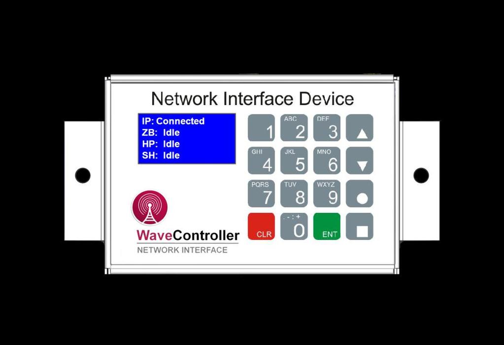
8 Actions for: WaveControllers Display remains on version number or IP: reads NONE Display blank INFORMATION This may indicate the cellular signal strength is too low or not present. Move WaveController to location near a window or door and re-power. Check for connectivity, using these steps: 1. IP reads CONNECTED. Use the following steps to check for signal strength: a. On WaveController keypad, press the bottom right button with the square. b. Watch the line under IP for a number followed by,99. The number to the left of the "," indicates the signal strength. For example, 15,99 would indicate a signal strength of 15. c. Press the square button again to return to regular operation. 2. IP still reads NONE. This may indicate that the modem is not working properly. The display needs to be initialized again. Repower WaveController. The following are the actions for each step: 1. If the signal strength is: a. 0,99 to 10,99, a cell booster maybe be necessary. Refer to WaveRider Connectivity Tutorial b. 11,99 or higher, the WaveController would best be mounted in its present location. 2. Contact Customer Service for further options. No further action if problem corrected Upon power-up, the WaveReader will display the version number, then change to an information screen that will remain until the reader connects to the WaveController. On the top line of the information screen, the P:24xx refers to the PAN that the WaveReader has either joined or is trying to join. Once this number matches the PAN of the WaveController, the display should change to Insert Card, if the reader has been linked properly to the controller. There are 8 possible PAN numbers 2425, 2426, 2427, 2428, 2429, 242A, 242B, & 242C. Generally, if there is only one laundry room at a location, the default WaveController PAN is 2425, so as the WaveReader scrolls through the PAN numbers, it should stop on 2425 and connect, again, if the reader has been properly linked to the controller. For more complete information about linking WaveReaders to WaveControllers, refer to the document entitled, DOC-WaveControllerLink. The WaveReader to WaveController Troubleshooting Guide assumes that the readers have been previously linked to the controllers. 8
, re-power the reader. 2.")
9 Actions for : WaveControllers to WaveReaders Follow these steps in order: The following are the actions for each step: WaveReader display stays on information screen 1. On the top line of the information screen, locate the P:24xx. If the WaveReader is scrolling fast (10 seconds or less between PAN numbers), re-power the reader. 2. If the WaveReader passes the PAN for the WaveController more than twice, re-power the reader. 3. If the WaveReader continues to pass the WaveController PAN, confirm the reader is actually linked with the machine in the WaveController. Follow the steps below to verify: a. With the WaveController on the CONNECTED screen, press any number to enter the configuration screen. b. When prompted for the PIN, press and then press enter. c. In configuration mode, press the down arrow button to go to the second menu. d. Press 1 to enter Reader Names. e. Use the 2: Next Reader button until the machine number for the reader appears beside the 1. f. Press 1. On the top line, the machine number and the 4- character ZB should be present. 1. No further action if problem corrected 2. No further action if problem corrected 9
10 Actions for: WaveControllers to WaveReaders (continued) g. If the machine number and the ZB are correct, allow more time for the WaveReader to connect. It can take from minutes, at times, depending on several factors, including the number of machines in the room. WaveReader display stays on information screen 3. g. No further action if WaveReader connects within 30 minutes. If reader fails to connect in 30 minutes, contact Customer Service for further assistance h. If the line reads NO ZB, the reader is not properly linked to the WaveController. 3. h. If the WaveReader is not properly linked to the WaveController, follow these steps in order: i. Press Clear button to escape to the previous menu. ii. Press Clear button once more to escape to the second menu. iii. Press 2: Configure ZB iv. 1 should show any 4-character reader ZB that is not currently linked. v. Press 1 if this is the correct reader ZB. Otherwise, use the 2: Next ZB button to scroll through all reader ZBs and press 1 when the correct ZB is reached. vi. 1 should show any machine ID that is not currently linked. Once the correct machine ID is reached, press 1 to link the reader and the controller. vii.press 2: Save and the display will return to the main Configure ZB screen. viii.press 3: Save All NOTE: This step is very important. Failure to Save All will result in a linking failure and the WaveReader will continue to search for the WaveController. ix. Once all linking is complete, press Clear to exit back to the Connected screen. 4. WaveReader refuses to connect after all of the above 4. Contact Customer Service for further assistance 10

11 Actions for: WaveReaders to WaveCentral INFORMATION All machines must be set up and configured in WaveCentral prior to the installation. In the event that something has been configured incorrectly, changes must be made in WaveCentral by the individual with administrative access. In some cases, this may be the technician servicing the location. The following information is intended to assist in troubleshooting problems between the reader and WaveCentral. WaveReader display reads Waiting for Config Data Reader may be configured incorrectly for type of machine. No further action if problem corrected Or Check machine type in Room Layout on WaveCentral. If incorrect, right-click on machine and select Delete. Add machine back into the room layout with the correct machine type and configuration information. If problem persists, contact Customer Service Display reads In Use when machine is idle (Quantum/MDC/PR models only) NOTE: All readers in the room will have to be relinked to the WaveController. Follow the steps below in order: 1. Disconnect power to all machines in laundry room but leave WaveController powered. Or 2. With the WaveController on the CONNECTED screen, press any number to enter the configuration screen. 3. When prompted for the PIN, press and then press enter. WaveReader alternates between Insert Card and In Use 4. In configuration mode, press the down arrow button to go to the second menu. 5. Reconnect power to all machines in laundry room. 6. Wait 5 minutes to give the readers time to attempt connection to the WaveController. 7. On WaveController, press 2: Configure ZB Repeat the linking process accomplished before the change. 11
12 Actions for: WaveReaders to WaveCentral (continued) WaveReader reads Declined Low Balance The vend price for the reader may be set to a value greater than the Max Vend Price set on the Room Set-up page. Verify the Max Vend Price: 1. On the Room Set-up page, select the room you wish to verify and select the Edit button. 2. Scroll down to Max Vend Price and ensure the price is equal to or greater than the maximum vend price in the laundry room. 3. Save any changes. 4. Cycle power to the WaveController. This will force the controller to reconnect to WaveCentral and get the new Max Vend Price. 5. If this does not correct the problem with the reader, contact Customer Service for further assistance. 12


13 Customer Service Process & Escalation If you require support for any component of your card payment system, Heartland MicroPayments has a team of dedicated Customer Service Representatives to assist you. Please use the following steps to contact our team. If the issue has not been resolved to your satisfaction in Step-1, please escalate the issue to the next step, detailed below: , Press 2 to be connected to a Customer Service Representative. Alternatively, you may us at HMPSupport@e-hps.com , Extension 6273 to be connected the Customer Service Manager to be connected to the Director of Operations & Customer Service 4 Contact your Regional Sales Manager 13


 2115 Chapman Road, Suite")

14 Laundry Customer Guide Returning Equipment for Repair Service 1 Obtain a description of the item to be returned, a description of the problem the item has, and the serial number of the item. 2 Call , Press 2 to be connected to a Customer Service Representative (CSR) 3 The CSR will help determine warranty status and advise you of options 4 If item is to be returned for repair, the CSR will issue a Return Materials Authorization Number (RMA#) to you.** 5 Return the item to: Heartland MicroPayments Attn: RMA# (include RMA # here) 2115 Chapman Road, Suite 159 Chattanooga, TN After repair charges (if applicable) have been determined and approved, the repairs will be conducted and the item returned to the client. **Note: Items returned without an RMA# may be refused, or their processing will be significantly delayed. 14
15 Warranty Policy Heartland MicroPayments standard warranty period is one year from the date of shipment. Heartland MicroPayments warrants that during the warranty period equipment shall be free from defects in materials, workmanship, and fabrication, and shall conform to applicable specifications, drawings, samples and/or description. Heartland MicroPayments hardware products are warranted against defects in materials and workmanship when purchased from Heartland MicroPayments or an authorized Heartland MicroPayments dealer and subject to normal use and service during the warranty period. If Heartland MicroPayments receives notice of such defects during the warranty period, Heartland MicroPayments will, at its option, either repair or replace without charge, hardware products which prove to be defective, except as set forth below. All replaced parts become the property of Heartland MicroPayments. This Limited Warranty shall not apply to equipment failure resulting from: 1. Improper or inadequate maintenance by purchaser, including failure to follow published cleaning schedules. Heartland MicroPayments recommends that the card reader units and bill validators be cleaned every two weeks (minimum). Due to environmental conditions, the cleaning procedure may be required more frequently. Card reader cleaning cards and bill validator cleaning cards may be purchased from Heartland MicroPayments. 2. Purchaser supplied software, hardware or interfacing, including reprogramming, which may cause excessive repetition of electro-mechanical or electronic drive components. 3. Unauthorized or non-heartland MicroPayments modifications to the product or misuse of the product. 4. Operation outside the following environmental or electrical specifications for the product: 41 to 104 degrees Fahrenheit (+5 C to +40 C) 20% - 80% relative humidity, non-condensing Volts AC, 50/60 Hz 5. Improper site preparation and maintenance. 6. Accident, disaster or vandalism. The foregoing warranties shall be subject to purchaser's installing and maintaining the equipment in accordance with the specifications and directions supplied by Heartland MicroPayments, and the customer shall be responsible for all transportation charges on warranty replacement or repair items returned to Heartland MicroPayments. Heartland MicroPayments makes no representations or warranties other than those set forth. The warranty stated herein is expressly in lieu of all other warranties, express or implied, including, but not limited to, any express or implied warranty of merchantability or fitness for a particular purpose, or against infringement, and such warranty constitutes the only warranty made by Heartland MicroPayments with respect to this agreement to the Heartland MicroPayments products listed, articles, materials, replacement parts, or services to be supplied hereby. Heartland MicroPayments shall not be liable for any incidental or consequential damages of any kind. 15
4X1 Gefen TV Switcher GTV-HDMI N. User Manual
 4X1 Gefen TV Switcher GTV-HDMI1.3-441N User Manual INTRODUCTION Congratulations on your purchase of the 4x1 GefenTV Switcher. Your complete satisfaction is very important to us. GefenTV GefenTV is a unique
LavryBlack Series Model DA10 Digital to Analog Converter
 LavryBlack Series Model DA10 Digital to Analog Converter Lavry Engineering, Inc. P.O. Box 4602 Rolling Bay, WA 98061 http://lavryengineering.com email: techsupport@lavryengineering.com January 14, 2008
Model R177M and R177S Baseband Switch
 Model R177M and R177S Baseband Switch Installation Guide P/N 1340192 082304 Monroe Electronics 100 Housel Ave Lyndonville NY 14098-0535 800-821-6001 585-765-2254 fax 585-765-9330 www.monroe-electronics.com
VGA CAT-5 1:8 Distribution S VGA CAT-5 Distribution R. EXT-VGA-CAT5-148S EXT-VGA-CAT5-148R User Manual
 VGA CAT-5 1:8 Distribution S VGA CAT-5 Distribution R EXT-VGA-CAT5-148S EXT-VGA-CAT5-148R User Manual INTRODUCTION Congratulations on your purchase of the VGA CAT-5 1:8 Distribution S. Your complete satisfaction
VideoEase HDMI 3x1 Switcher Kit (110V) Installation Guide
 Installation Guide") VideoEase HDMI 3x1 Switcher Kit 500410 (110V) Installation Guide P/N: 94-00628-A SE-000627-A Copyright Notice : Copyright 2008 MuxLab Inc. All rights reserved. Printed in Canada. No part of this publication
VideoEase HDMI 3x1 Switcher Kit 500410 (110V) Installation Guide P/N: 94-00628-A SE-000627-A Copyright Notice : Copyright 2008 MuxLab Inc. All rights reserved. Printed in Canada. No part of this publication
Model No. ST100 VTR CONTROLLER
 12843 Foothill Blvd. Suite C Sylmar, California 91342 V: 818.898.3380 F: 818.898.3360 sales@dnfcontrols.com Model No. ST100 VTR CONTROLLER For Version 6.x and 7.x Units USER MANUAL Rev 3.12 Table of Contents
Model No. ST200-S. Universal VTR/DDR. Controller USER MANUAL 1 ST200-S. Manual Version Document No... ST200-S_User_Manual
 12843 Foothill Blvd. Suite C Sylmar, California 91342 V: 818.898.3380 F: 818.898.3360 sales@dnfcontrols.com Model No. ST200-S Universal VTR/DDR Controller USER MANUAL Manual Version.... 3.11 102506 Document
ST60-DVC VTR CONTROLLER ST60-AG57 VTR CONTROLLER
 12843 Foothill Blvd. Suite C Sylmar, California 91342 V: 818.898.3380 F: 818.898.3360 sales@dnfcontrols.com ST60-DVC VTR CONTROLLER ST60-AG57 VTR CONTROLLER USER MANUAL Manual Version.... 2.1 122203 Document
SC-C1M SiriusConnect TM Vehicle Tuner
 SC-C1M SiriusConnect TM Vehicle Tuner For Special Market Applications Installation Guide Congratulations on the Purchase of your new SIRIUS SC-C1 SiriusConnect TM Vehicle Tuner. The SC-C1M is packaged
Warranty and Registration. Warranty: One Year. Registration: Please register your product at Port, or. or Windows.
 7 7 Port, or or Windows Port Warranty and Registration Warranty: One Year Registration: Please register your product at www.aitech.com 2007 AITech International. All rights reserved. WEB CABLE PLUS PC-TO-TV
MaxView Cinema Kit Quick Install Guide
 SYSTEM SETUP The MaxView will work at any of the following display settings: INSTALLATION MaxView Cinema Kit Quick Install Guide Step 1 - Turn off your computer. Disconnect your monitor s VGA cable from
HDTV SIGNAL AMPLIFIERS. 34 series USER GUIDE GUÍA PARA EL USUARIO MODE D EMPLOI CM-3410 CM-3412 CM-3414 CM-3418
 HDTV SIGNAL AMPLIFIERS 34 series USER GUIDE GUÍA PARA EL USUARIO MODE D EMPLOI CM-3410 CM-3412 CM-3414 CM-3418 Table of Contents Product Overview... 3 Package Contents and Accessories... 3 Instructions...4
32 Channel CPCI Board User Manual
 0 Sections Page 1.0 Introduction 1 2.0 Unpacking and Inspection 1 3.0 Hardware Configuration 1 4.0 Board Installation 5 5.0 I/O Connections and the Front Panel 5 5.1 Front Panel Layout 5 5.2 Input and
VGA CAT-5 1:8 Distribution S VGA CAT-5 Distribution R
 VGA CAT-5 1:8 Distribution S VGA CAT-5 Distribution R EXT-VGA-CAT5-148S EXT-VGA-CAT5-148R User Manual www.gefen.com ASKING FOR ASSISTANCE Technical Support: Telephone (818) 772-9100 (800) 545-6900 Fax
FDVGA-SDI. Installation and Operation Manual. VGA to HDSDI Converter. Revision Date: 09/10/2014 Page 1 of 9. Rev: B. Document Number: MAN FDVGA-SDI
 Page 1 of 9 Installation and Operation Manual FDVGA-SDI VGA to HDSDI Converter Page 2 of 9 FDVGA-SDI VGA to HDSDI Converter 2014 Flight Display Systems. Flight Display Systems 6435 Shiloh Road Alpharetta,
USER INSTRUCTIONS MODEL CSI-200 COAXIAL SYSTEM INTERFACE
 USER INSTRUCTIONS MODEL CSI-200 COAXIAL SYSTEM INTERFACE 9350-7676-000 Rev B, 5/2001 PROPRIETARY NOTICE The RTS product information and design disclosed herein were originated by and are the property of
FD104CV. Installation and Operation Manual 10.4 LCD. Revision Date: 08/01/2017 Page 1 of 14. Rev: G. Document Number: MAN FD104CV
 Page 1 of 14 Installation and Operation Manual FD104CV 10.4 LCD Page 2 of 14 Table of Contents eneral Information... 3 Front View... 3 Additional Information... 3 Specifications... 4 Installation Instructions...
Model No. ST60-S (-SRN, -SRK, -DRN, -DRK)
") 12843 Foothill Blvd., Suite D Sylmar, CA 91342 818 898 3380 voice 818 898 3360 fax www.dnfcontrols.com Model No. ST60-S (-SRN, -SRK, -DRN, -DRK) VTR CONTROLLER Sony Protocol USER MANUAL Manual Version.........
12843 Foothill Blvd., Suite D Sylmar, CA 91342 818 898 3380 voice 818 898 3360 fax www.dnfcontrols.com Model No. ST60-S (-SRN, -SRK, -DRN, -DRK) VTR CONTROLLER Sony Protocol USER MANUAL Manual Version.........
Model PSKIT-H540 Ultrasonic Power Supply Kit 40 khz 500 Watts
 Model PSKIT-H540 Ultrasonic Power Supply Kit 40 khz 500 Watts INSTRUCTION MANUAL Sonics & Materials, Inc. 53 Church Hill Road Newtown, CT 06470 USA 203.270.4600 800.745.1105 203.270.4610 fax www.sonics.com
Home Kit. Model XM101HK
 Home Kit Instruction Manual Model XM101HK Important: This manual contains important safety and operating information. Please read, understand, and follow the instructions in this manual. Failure to do
DVI Rover 700 User Guide
 DVI Rover 700 User Guide Featuring ExtremeDVI Technology DVI Rover 700 This document applies to Part Numbers: 00-00106 through 00-00141 inclusive. FCC Radio Frequency Interference Statement Warning The
Precision TNC Coaxial Calibration Kit
 User Guide Precision TNC Coaxial Calibration Kit DC to 18 GHz Models: 8650CK10/11 8650CK20/21 8650-511 (A) 2/15 User Guide Precision TNC Coaxial Calibration Kit DC to 18 GHz Models: 8650CK10/11 8650CK20/21
OWNER S MANUAL. Model 861 Hand Held Bale Scanner # REVISED 4-10
 OWNER S MANUAL Model 861 Hand Held Bale Scanner #010-0861 REVISED 4-10 HARVEST TEC 861 TABLE OF CONTENTS PAGE INTRODUCTION 3 OVERVIEW 4 INSTALLATION OF ANTENNA 5 1. INSTALLATION OF ANTENNA FOR HAND HELD
MAN FDAIP-CVH VER HDSDI
 Page 1 of 12 Installation and Operation Manual FDAIP-CVH VER HDSDI Auxiliary Input Panel Composite, VGA, HDMI Page 2 of 12 FDAIP-CVH VER HDSDI Auxiliary Input Panel Composite, VGA, HDMI 2013 Flight Display
ALPHA Personal Priority Display User Manual
 ALPHA Personal Priority Display User Manual PERSONAL PRIORITY DISPLAY 1997 Adaptive Micro Systems Form No. 9708-5002 12/10/97 i NOTE: Due to continuing product innovation, specifications in this document
DICKSON ES120/ES120A DICKSON. Electronic Signal Data Logger. Specifications. Applications, Features, & Getting Started. Instructions / Operating
 /A Electronic Signal Data Logger Contents: Product Applications and Useful Features Product Transmitter / DicksonWare Software Product Frequently Asked Questions Warranty / Software & FAQs & Product Applications
DVI Over Cat5 2x2 Matrix Switch. Model: B
 WARRANTY REGISTRATION Register online today for a chance to win a FREE Tripp Lite product www.tripplite.com/warranty Owner s Manual DVI Over Cat x Matrix Switch Model: B10-0 Package Contents Product Features
INSTALLATION MANUAL Model: HMDD. ATSC/QAM Digital Mini Demodulator
 INSTALLATION MANUAL Model: HMDD ATSC/QAM Digital Mini Demodulator 1 PACKAGE CONTENTS This package contains: One HMDD ATSC/QAM Mini Demodulator One HMDD Installation Manual PRODUCT DESCRIPTION The HMDD
FD70CV-M-C-6. Installation and Operation Manual. 7 Widescreen LCD /Standard Arm. Revision Date: 05/05/2017 Page 1 of 13. Rev: B
 Page 1 of 13 Installation and Operation Manual FD70CV-M-C-6 7 Widescreen LCD /Standard Arm Page 2 of 13 Table of Contents General Information...3 Front View...3 Specifications...4 Installation Instructions...4
Owner s Manual. HDMI over Cat5/Cat6 Active Extender with Built-in 4K Upscaler. Models: B126-1A0-SC4K and B126-1A1-SC4K
 Owner s Manual HDMI over Cat5/Cat6 Active Extender with Built-in 4K Upscaler Models: B126-1A0-SC4K and B126-1A1-SC4K PROTECT YOUR INVESTMENT! Register your product for quicker service and ultimate peace
ISIS intouch NET Wi Fi Touch Screen Controller Owner s Manual and Instruction Guide
 ISIS intouch NET Wi Fi Touch Screen Controller Owner s Manual and Instruction Guide Table of Contents Overview... 2 Warnings... 3 Kit Includes... 4 Installation Steps... 5 Locate the intouch NET module
CGA0101 Wireless Cable Gateway Quick Installation Guide
 Package Contents CGA0101 cable modem * 1 Quick Installation Guide * 1 RJ-45 CAT 5e cable * 1 Rear Panel and Hardware Connection 12 V/1.5 A Power Adaptor * 1 Telephone cord * 1 This chapter describes the
Operating Manual for Clock / Auxiliary Displays for VHX systems
 Operating Manual for Clock / Auxiliary Displays for VHX systems The VHX auxiliary display module is designed to work with a Dakota Digital VHX system and will not function properly on its own. With this
Table of Contents. Introduction Pin Description Absolute Maximum Rating Electrical Specifications... 4
 Table of Contents Introduction... 1 Pin Description... 2 Absolute Maximum Rating... 3 Electrical Specifications... 4 Mechanical Specifications... 5 Thermal Specifications... 6 Over Temperature Protection...
Model No. ST60-SPS (-SRN, -SRK, -DRN, -DRK)
") 12843 Foothill Blvd. Suite C Sylmar, California 91342 V: 818.898.3380 F: 818.898.3360 sales@dnfcontrols.com Model No. ST60-SPS (-SRN, -SRK, -DRN, -DRK) VTR CONTROLLER Sony Protocol USER MANUAL Table of
12843 Foothill Blvd. Suite C Sylmar, California 91342 V: 818.898.3380 F: 818.898.3360 sales@dnfcontrols.com Model No. ST60-SPS (-SRN, -SRK, -DRN, -DRK) VTR CONTROLLER Sony Protocol USER MANUAL Table of
CN12 Technical Reference Guide. CN12 NTSC/PAL Camera. Technical Reference Guide PCB Rev
 CN12 NTSC/PAL Camera Technical Reference Guide PCB Rev 1.0 www.soc-robotics.com Copyright 2010. SOC Robotics, Inc. 1 Manual Rev 0.90 Warranty Statement SOC Robotics warrants that the Product delivered
USER MANUAL FOR THE ANALOGIC GAUGE FIRMWARE VERSION 1.0
 by USER MANUAL FOR THE ANALOGIC GAUGE FIRMWARE VERSION 1.0 www.aeroforcetech.com Made in the USA! WARNING Vehicle operator should focus primary attention to the road while using the Interceptor. The information
SINCE User Manual 7 DAY PROGRAMMABLE DIGITAL TIMER MODEL PS-100. The best solutions for automation and protection.
 SINCE 1973 User Manual 7 DAY PROGRAMMABLE DIGITAL TIMER MODEL PS-100 The best solutions for automation and protection www.nassarelectronics.com Description The PS-100 is a 7 day programmable digital timer
Enable-IT 821P PoE Extender Quickstart Guide Professional Grade Networking
 ! Enable-IT 821P PoE Extender Quickstart Guide Professional Grade Networking All Rights Reserved 1997-2016 Enable-IT, Inc. INSTALLING THE 821P POE EXTENDER The Enable-IT 821P PoE Extenders have a distance
RemotePoint. Navigator. User s Manual VP4150
 RemotePoint Navigator User s Manual VP4150 LASER Safety Statement CAUTION: Use of controls or adjustments or performance of procedures other than those specified herein may result in hazardous radiation
LED Series Sealed Backlights
 For use with any Vision system Rugged, waterproof housing, rated IEC IP67 Mounts directly from the back or surface mount using available brackets Smooth exterior for easy cleaning Diffused backlights for
FD102CV. Installation and Operation Manual Widescreen LCD. Revision Date: 02/01/2012 Page 1 of 16. Rev: K. Document Number: MAN FD102CV
 Page 1 of 16 Installation and Operation Manual FD102CV 10.2 Widescreen LCD Page 2 of 16 FD102CV 10.2 Widescreen LCD 2006 Flight Display Systems. Flight Display Systems 6435 Shiloh Road Alpharetta, GA 30005
VHF + UHF Amplified HDTV Antenna Model OA8000 & OA8001 Installation Instructions Reception Frequencies
 VHF + UHF Amplified HDTV Antenna Model OA8000 & OA8001 Installation Instructions Reception Frequencies VHF: 54-216 MHz UHF: 470-698 MHz FM: 87.9-107.9 MHz Voltage Input: AC110-120V / AC220-240V Working:
Enable-IT 824WP Outdoor Waterproof PoE Extender Kit Quickstart Guide Professional Grade Networking
 ! Enable-IT 824WP Outdoor Waterproof PoE Extender Kit Quickstart Guide Professional Grade Networking All Rights Reserved 1997-2018 Enable-IT, Inc. INSTALLING THE 824WP GIGABIT ETHERNET EXTENDER The Enable-IT
HDS-21R / 41R. Owner s Manual. The World s Best 2x1 / 4x1 HDMI Switch. PureLink TM
 HDS-21R / 41R The World s Best 2x1 / 4x1 HDMI Switch Owner s Manual PureLink TM 535 East Crescent Avenue Ramsey, NJ 07446 USA Tel: +1.201.488.3232 Fax: +1.201.621.6118 E-mail: sales@purelinkav.com www.purelinkav.com
AWT150C/AWT150CS/ AWT151C CCD Camera
 AWT150C/AWT150CS/ AWT151C CCD Camera ISSUED OCTOBER 2018 WARNING Failure to follow all instructions and safety precautions in this manual, in the vehicle and body manufacturers' manuals and on the safety
VGA Extender SRN. EXT-VGA-141SRN. User Manual
 VGA Extender SRN EXT-VGA-141SRN User Manual www.gefen.com ASKING FOR ASSISTANCE Technical Support: Telephone (818) 772-9100 (800) 545-6900 Fax (818) 772-9120 Technical Support Hours: 8:00 AM to 5:00 PM
Introduction. Package Contents. Installation Requirements
 Security Camera Security Camera Introduction Introduction Thank you for purchasing the aircam Dome. This Quick Start Guide is designed to guide you through the installation of the aircam Dome and show
RD RACK MOUNT DIMMER OWNERS MANUAL VERSION /09/2011
 RD - 122 RACK MOUNT DIMMER OWNERS MANUAL VERSION 1.3 03/09/2011 Page 2 of 14 TABLE OF CONTENTS UNIT DESCRIPTION AND FUNCTIONS 3 POWER REQUIREMENTS 3 INSTALLATION 3 PLACEMENT 3 POWER CONNECTIONS 3 OUTPUT
FTC AGL System Controller Reference Manual Part Number
 SERIAL NUMBER FTC 190-1 AGL System Controller Reference Manual Part Number 7911901 Flash Technology, 332 Nichol Mill Lane, Franklin, TN 37067 (615) 261-2000 Front Matter Abstract This manual contains information
FD171CV-C-4. Installation and Operation Manual. 17 HDSDI Special Mission Quad Monitor. Revision Date: 01/11/2017 Page 1 of 14.
 Page 1 of 14 Installation and Operation Manual FD171CV-C-4 17 HDSDI Special Mission Quad Monitor Page 2 of 14 Table of Contents General Information...3 Front View...3 Additional Information...3 Specifications...4
MLA-XLR MIDI Line Amplifier
 MIDI Line Amplifier Users Manual , and 0 are trademarks of JLCooper Electronics. All other brand names are the property of their respective owners. User s Manual, First Edition Part Number 932090 2002
Stretch HDMI TM. User s Manual (M1-2000)
") Stretch HDMI TM User s Manual (M1-2000) Manual Contents Manual Contents 1-0 Welcome!, Product Description 1-1 System Requirements for Setup 1-2 Installation 1-3 Troubleshooting, Maintenance, Technical
Stretch HDMI TM User s Manual (M1-2000) Manual Contents Manual Contents 1-0 Welcome!, Product Description 1-1 System Requirements for Setup 1-2 Installation 1-3 Troubleshooting, Maintenance, Technical
VGA Extender SRN. EXT-VGA-141SRN User Manual.
 VGA Extender SRN EXT-VGA-141SRN User Manual www.gefen.com ASKING FOR ASSISTANCE Technical Support: Telephone (818) 772-9100 (800) 545-6900 Fax (818) 772-9120 Technical Support Hours: 8:00 AM to 5:00 PM
Cablesson HDelity 7.1ch Audio Extractor & Mixer. User Manual
 Cablesson HDelity 7.1ch Audio Extractor & Mixer User Manual All rights reserved - CABLESSON All rights reserved - CABLESSON ! SAFETY AND NOTICE The Cablesson HDelity HDMI 7.1ch Audio Extractor and Mixer
APSPB PUSH BUTTON ZERO Installation Manual
 APSPB PUSH BUTTON ZERO Installation Manual CARDINAL SCALE MFG. CO. 8527-0579-0M Rev A 203 E. Daugherty, Webb City, MO 64870 USA Printed in USA 12/14 Ph: 417-673-4631 Fax: 417-673-2153 www.detectoscale.com
Dystrybucja i sprzedaż: Meditronik Sp. z o.o Warszawa, ul. Wiertnicza 129, tel. (+48 22) , fax (+48 22)
 , fax (+48 22)") Optional Accessories DVI RS232 Extender N Send flawless hi-def video and RS232 signals over two economical CAT-5 cables -- up to 300 feet away. Extending state-of-the-art digital video displays, computer
Optional Accessories DVI RS232 Extender N Send flawless hi-def video and RS232 signals over two economical CAT-5 cables -- up to 300 feet away. Extending state-of-the-art digital video displays, computer
With Latency Killer TM Technology. Model LK-Solo. HP Amp 2x2 Loop Thru Mixer
 With Latency Killer TM Technology Model LK-Solo HP Amp 2x2 Loop Thru Mixer Lavry Engineering, Inc. P.O. Box 4602 Rolling Bay, WA 98061 www.lavryengineering.com November 20, 2014 Rev 2.0 2 Table of Contents
Operation Manual VMS 3.0 Video System
 Operation Manual VMS 3.0 Video System for the AlterG Anti-Gravity Treadmill 1 This manual covers operation procedures for the following AlterG products: AlterG Video System model VMS 3.0 NOTE: The following
*Prefer. 600 MHz 4K ULTRA. 60Hz, 4:4:4. over one SC-Terminated Fiber-Optic Cable EXT-DP-4K600-1SC. User Manual. Release A1
 *Prefer 600 MHz 4K ULTRA 60Hz, 4:4:4 DisplayPort 1.2 Extender over one SC-Terminated Fiber-Optic Cable EXT-DP-4K600-1SC User Manual Release A1 Important Safety Instructions 1. Read these instructions.
1:2 VGA Audio Over CAT5
 1:2 VGA Audio Over CAT5 EXT-COMPAUD-CAT5-142 User Manual www.gefen.com Technical Support: Telephone (818) 772-9100 (800) 545-6900 Fax (818) 772-9120 Technical Support Hours: 8:00 AM to 5:00 PM Monday thru
Enable-IT 865 Q PRO Gigabit Professional Grade PoE Extender Kit Quickstart Guide
 Enable-IT 865 Q PRO Gigabit Professional Grade PoE Extender Kit Quickstart Guide INSTALLING THE 865 Q PRO POE EXTENDER KIT The Enable-IT 865 Q PRO PoE Extenders have a distance restriction of 1,500ft (458m)
Installation and Tuning Manual DAC 7000 DAC 2X
 Installation and Tuning Manual DAC 7000 DAC 2X DISCLAIMER While every effort has been made to ensure the accuracy of this document, Wayne s, Inc. nor its dealers assumes any responsibility for omissions
Owner s Manual. VGA + Audio to HDMI Adapter/Scaler. Model: P HDSC2
 Owner s Manual VGA + Audio to HDMI Adapter/Scaler Model: P116-000-HDSC2 Combines a VGA video and RCA stereo audio signal for use with an HDMI display Supports VGA input video resolutions up to 1920 x 1440
Owner s Manual HDMI over Cat5 Active Extender
 Owner s Manual HDMI over Cat5 Active Extender Models: B126-1A1-U and B126-1A0-U PROTECT YOUR INVESTMENT! Register your product for quicker service and ultimate peace of mind. You could also win an ISOBAR6ULTRA
Elite Silvermax Series
 Electric Projection Screen Elite Silvermax Series USER S GUIDE IMPORTANT SAFETY INSTRUCTIONS Please read this guide prior to installation. Make sure the current rating is equal to the appliance rating
User Guide. Single-Link DVI Active Cable Extender. DVI-7171c
 User Guide Single-Link DVI Active Cable Extender DVI-7171c TABLE OF CONTENTS SECTION PAGE PRODUCT SAFETY...1 PRODUCT LIABILITY...1 1.0 INTRODUCTION...2 2.0 SPECIFICATIONS...3 3.0 PACKAGE CONTENTS...4 4.0
TRIPLETT. PairMaster. Lan Cable Test Set. Instruction Manual
 TRIPLETT PairMaster Lan Cable Test Set Instruction Manual The PairMaster LAN CABLE TEST SET INSTRUCTION MANUAL IMPORTANT SAFETY INSTRUCTIONS SAVE THESE INSTRUCTIONS Before using the PairMaster, read all
HD Digital MPEG2 Encoder / QAM Modulator
 HD Digital MPEG2 Encoder / QAM Modulator YPrPb VGA In QAM Out series Get Going Guide ZvPro 600 Series is a one or two-channel Component or VGA-to-QAM MPEG 2 Encoder/ Modulator, all in a compact package
Model Number ALS-ELUM-RGB-CNTRL-1. elum RGB Controller
 Model Number ALS-ELUM-RGB-CNTRL-1 Installation INSTRUCTIONS elum RGB Controller Table of Contents 1.0 General Information..... 2.0 Connections...... 3.0 Switches......... 4.0 Indicators... 5.0 DMX Operation...
Satellite Radio. Expand Your Factory Radio ISSR bit & 29-bit LAN. Owner s Manual Gateway. add. Harness Connection USB. Port 1 Port.
 Expand Your Factory Radio Harness Connection add Satellite Radio Dip Switches Port 1 Port 2 (See Manual) USB GM 11-bit & 29-bit LAN Owner s Manual Gateway ISSR12 Table of Contents 1. Introduction 2. Precautions
The Phono Box SUMIKO Fifth Street Berkeley, CA sumikoaudio.com
 The Phono Box SUMIKO 2431 Fifth Street Berkeley, CA 94710 510.843.4500 sumikoaudio.com In the past, all audio system control components (integrated amplifiers, receivers and system pre-amplifiers) had
DA8-T DA8-T MANUAL
 J C F A U D I O MANUAL 1.0 contact@jcfaudio.com www.jcfaudio.com Safety Information Do not repair, modify, service this device except in the manner in which it is described in this manual. Doing so can
ACCESSORIES MANUAL PART NUMBER: PRODUCT REVISION: 1 TNP100. Tilt N Plug Interconnect Box USER'S GUIDE
 MANUAL PART NUMBER: 400-0091-001 PRODUCT REVISION: 1 TNP100 Tilt N Plug Interconnect Box USER'S GUIDE INTRODUCTION Your purchase of the TNP100 Tilt N Plug Interconnect Box is greatly appreciated. We are
Owner s Manual. HDMI + IR over Dual Cat5/Cat6 Extender Kit. Model: B IR
 Owner s Manual HDMI + IR over Dual Cat5/Cat6 Extender Kit Model: B125-101-60-IR PROTECT YOUR INVESTMENT! Register your product for quicker service and ultimate peace of mind. You could also win an ISOBAR6ULTRA
PRO-ScalerV2HD VGA to HDMI & Audio Scaler Converter. User s Guide. Made in Taiwan
 VGA to HDMI & Audio Scaler Converter User s Guide Made in Taiwan Congratulations for owning a gofanco product. Our products aim to meet all your connectivity needs wherever you go. Have fun with our products!
MWT-FM. Operation Manual. FM Single Channel Transmitter. man_mwtfm.
 MWT-FM FM Single Channel Transmitter Operation Manual man_mwtfm www.myeclubtv.com CONTENTS FCC COMPLIANCE STATEMENT. 3 INDUSTRY CANADA COMPLIANCE 3 MWT-FM ORIENTATION. 4 SAFETY PRECAUTIONS 5 FINDING FM
VGA Extender over Single CAT 6 Cable with Audio Support. Model Extend both video and audio up to 1000 feet
 VGA Extender over Single CAT 6 Cable with Audio Support Model 103004 Extend both video and audio up to 1000 feet Utilize a Cat 6 cable instead of a bulky VGA cable Supports a local monitor and local speakers
Thermo-Simple 1 version 2 (TS.1 ver.2) 2013
 2013") Refrigeration Innovation Thermo-Simple 1 version 2 Manual Refrigeration Innovation 1250 Harter Avenue Suite E Woodland, CA 95776 P: 530.666.3020 Refrigeration Innovation, LLC. 1250 Harter Avenue, Suite
Refrigeration Innovation Thermo-Simple 1 version 2 Manual Refrigeration Innovation 1250 Harter Avenue Suite E Woodland, CA 95776 P: 530.666.3020 Refrigeration Innovation, LLC. 1250 Harter Avenue, Suite
LBC-H2CS-T/R-Lite LINK BRIDGE TM HDBASET HDMI 2.0 EXTEDER 4 PLAY
 LBC-H2CS-T/R-Lite LINK BRIDGE TM HDBASET HDMI 2.0 EXTEDER 4 PLAY BCI reserves the right to make changes to the products described herein without prior notice or consent. No liability is assumed as a result
DisplayPort Extender over 2 LC Fibers
 DisplayPort Extender over 2 LC Fibers Audio 3GSDI Embedder EXT-DP-CP-2FO User Manual Release A2 DisplayPort Extender over 2 LC Fibers Important Safety Instructions 1. Read these instructions. 2. Keep these
TRIPLETT WireMaster HDMI
 TRIPLETT WireMaster HDMI High Definition Cable Tester Instruction Manual 84-881 9/09 WireMaster HDMI FEATURES Lightweight, Rugged, Simple to use Test fragile, easily damaged HDMI Patch Cables and In-wall
1:4 3GSDI Splitter. EXT-3GSDI-144 User Manual.
 1:4 3GSDI Splitter EXT-3GSDI-144 User Manual www.gefen.com ASKING FOR ASSISTANCE Technical Support: Telephone (818) 772-9100 (800) 545-6900 Fax (818) 772-9120 Technical Support Hours: 8:00 AM to 5:00 PM
Instruction Manual 1T-CT-630 Series HDMI to CAT.6 Extender System
 99 Washington Street Melrose, MA 02176 Phone 781-665-1400 Toll Free 1-800-517-8431 Visit us at www.testequipmentdepot.com 1T-CT-631A 1T-CT-632 1T-CT-633 Instruction Manual 1T-CT-630 Series HDMI to CAT.6
Quick Installation Guide. Indoor / Outdoor Antenna, Antenna Cable & Surge Arrestor
 Quick Installation Guide Indoor / Outdoor Antenna, Antenna Cable & Surge Arrestor Table of Contents... 1 1. Outdoor Antenna Installation... 1 2. How to install the surge arrestor... 4 3. Weatherproof tape
GeniSys Display. Contractor s Tool. Description / Applications. for the GeniSys Advanced Burner Control
 PARTS & ACCESSORIES GeniSys Display or Contractor s Tool for the GeniSys Advanced Burner Control Description / Applications The Beckett GeniSys TM Display is an optional attachment for the GeniSys Primary
Electronic M.O.P Card. Instruction Manual Model D
 Electronic M.O.P Card Instruction Manual Model D10341-000 Table of Contents 1. General Description................................................................ 1 2. Specifications.....................................................................
COMPOSITE VIDEO (BNC) TO VGA VIDEO FORMAT CONVERTER AND SCALER AT-RGB110
 TO VGA VIDEO FORMAT CONVERTER AND SCALER AT-RGB110") User Manual COMPOSITE VIDEO (BNC) TO VGA VIDEO FORMAT CONVERTER AND SCALER AT-RGB110 TABLE OF CONTENTS 1. Introduction... 2 2. Package Contents... 2 3. Features... 2 4. Specification... 2 5. Panel Description...
User Manual COMPOSITE VIDEO (BNC) TO VGA VIDEO FORMAT CONVERTER AND SCALER AT-RGB110 TABLE OF CONTENTS 1. Introduction... 2 2. Package Contents... 2 3. Features... 2 4. Specification... 2 5. Panel Description...
OWNERS MANUAL. Revision /01/ Lightronics Inc. 509 Central Drive Virginia Beach, VA Tel
 OWNERS MANUAL Revision 1.8 09/01/2002 OWNERS MANUAL Page 2 of 12 AR-1202 UNIT DESCRIPTION The AR-1202 consists of a processor and 12 dimmer channels of 2.4KW each. Each dimmer channel is protected by a
1 x 10 Component Video with Stereo and Digital Audio Distribution Amplifier over CAT5/6 compatible with AT-COMP300RL AT-COMP10SS
 1 x 10 Component Video with Stereo and Digital Audio Distribution Amplifier over CAT5/6 compatible with AT-COMP300RL AT-COMP10SS User Manual www.atlona.com TABLE OF CONTENTS 1. Introduction 2 2. Features
DisplayPort Extender over 2 LC Fibers
 DisplayPort Extender over 2 LC Fibers Audio 3GSDI Embedder EXT-DP-CP-2FO User Manual Release A2 DisplayPort Extender over 2 LC Fibers Important Safety Instructions 1. Read these instructions. 2. Keep these
Dish Diversity Switch
 www.travel-vision.com Dish Diversity Switch INSTALLATION & USER S MANUAL Version 3.1 October 2013 PREFACE The information in this Installation and User s Manual is subject to change in order to improve
DUAL/QUAD DISPLAY CONTROLLER Operation Manual
 DUAL/QUAD DISPLAY CONTROLLER Operation Manual Model PXD524 MicroImage Video Systems division of World Video Sales Co., Inc PO Box 331 Boyertown, PA 19512 Phone 610-754-6800 Fax 610-754-9766 sales@mivs.com
AITech ProA/V Media Extender 5GHz Digital
 AITech ProA/V Media Extender 5GHz Digital 5 GHz Wireless Digital Media Transmitter and Receiver User Manual Table of Contents 1. Package Contents 2. Panels and Functions AV Sender AV Receiver 3. Setup
HDMI to Composite Converter. User s Guide
 1500548 HDMI to Composite Converter User s Guide We hope you enjoy your HDMI to Composite Converter from RadioShack. Add flexibility to your viewing experience by converting a digital HDMI video source
Owner s Manual. UHD 4Kx2K HDMI Splitters. Models: B UHD, B UHD, B UHD-WM, B UHD
 Owner s Manual UHD 4Kx2K HDMI Splitters Models: B118-002-UHD, B118-004-UHD, B118-004-UHD-WM, B118-008-UHD Product Features 2 Package Contents 3 Installation 4 Troubleshooting 5 Warranty & Product Registration
User Manual rev: Made in Taiwan
 CV-500S HDMI to Component/CVBS & Audio Scaler Converter User Manual rev: 131218 Made in Taiwan The CV-500S HDMI to Component/CVBS & Audio Scaler Converter has been tested for conformance to safety regulations
In-Line or 75 Ohm In-Line
 or 5 Ohm 1dB Adjustable Gain 800/1900 Smart Technology Contents: Quick Install Overview.... 2 Installation Diagram.... Understanding the Lights... 9 Warnings and Recommendations....11 Appearance of device
Owner s Manual. DisplayPort/Mini DisplayPort Cable Tester. Model: T DP
 Owner s Manual DisplayPort/Mini DisplayPort Cable Tester Model: T040-001-DP Este manual esta disponible en español en la página de Tripp Lite: www.tripplite.com/support Ce manuel est disponible en français
ACCESSORIES MANUAL PART NUMBER: TNP500. Universal Tilt N Plug Interconnect Box USER'S GUIDE
 MANUAL PART NUMBER: 400-0091-003 TNP500 Universal Tilt N Plug Interconnect Box USER'S GUIDE INTRODUCTION Your purchase of the TNP100 Tilt N Plug Interconnect Box is greatly appreciated. We are sure you