V Part # MAN-FIRSTLIGHT First Light Dv2 $45.00 USD. First Light
|
|
|
- Jasper Osborne
- 5 years ago
- Views:
Transcription


1 V Part # MAN-FIRSTLIGHT First Light Dv2 $45.00 USD First Light
2 First Light V This page intentionally left blank 2 M&R Companies 1N 372 Main St. Glen Ellyn, IL USA
3 V First Light Table of Contents 1. Safety and Operational Guidelines Management Responsibilities...6 Operator Responsibilities General Information Service and Parts Defined Purpose Warranty Product Specifications Installation Operation Control Panel (Timer Type A) Setting the 24 Hour Clock Control Panel UL (Timer Type B) Setting the Clock Making Screen Exposures Scheduled Maintenance Replacement Parts...20 M&R Companies 1N 372 Main St. Glen Ellyn, IL USA 3
4 First Light V This page intentionally left blank 4 M&R Companies 1N 372 Main St. Glen Ellyn, IL USA
5 V First Light 1. Safety and Operational Guidelines DANGER This symbol identifies situations that endanger people, property, and/or equipment. If such conditions exist, the equipment must be shut down and all energy sources (electrical, gas, and pneumatic) must be disconnected, purged, and locked out until the problem is resolved. Never attempt to bypass or defeat any safety device. Do not attempt to operate the equipment if any safety device is not functioning properly, or if any doubt exists about proper operation of safety devices. The product described in this publication may operate at high speed and contain numerous moving parts. It may employ natural gas or propane, mechanical or pneumatic forces, and/or hazardous voltages, and may create other conditions that could, through misuse, abuse, unauthorized alteration or retrofitting, inattention, or lack of understanding, result in injury, death, or damage to the product or to other equipment. In addition, improper operation may also depreciate the value of the machine and other assets of the owner, and impair the working efficiency of the machine. Energy Sources M&R equipment may use one of more of the following energy sources: Compressed Air (Pneumatic Energy) Electricity Gas (Natural Gas or Propane) Each form of energy presents its own unique hazards and requires appropriate precautions. Danger From Compressed Air (Pneumatic Energy) Only qualified personnel should be allowed to work on pneumatic components or assemblies. Before work is started on pneumatic components or assemblies, equipment should be disconnected from the air supply and all pneumatic lines should be purged to prevent accidental operation of pneumatic assemblies. All pneumatic pipes and hoses should be checked frequently for damage and wear. Danger From Electrical Energy Only qualified personnel should have access to electrical enclosures or work on electrical systems, and enclosures should be locked when not in use. Electrical equipment should be checked regularly. WARNING Failure to follow safety and maintenance procedures or to take appropriate corrected action when required can result in severe or fatal personal injuries, property damage, and/or damage to the equipment. M&R Companies 1N 372 Main St. Glen Ellyn, IL USA 5
6 First Light V Management Responsibilities Management Responsibilities 1. Ensure that this equipment is used only for the purposes set forth in the Defined Purpose section of this manual. 2. Ensure that all employees involved with the operation of this equipment or working near it read, understand, and act in accordance with the operational and safety standards set forth in this manual, including the Operator Responsibilities listed below. 3. Ensure that all recommended preventive maintenance is carried out according to M&R guidelines. 4. Should any problem arise which compromises the safe operation or normal functioning of this equipment, ensure that the equipment is immediately shut down, sources of power to the equipment is shut off and secured, and that personnel not trained to repair and directly involved in repairing the equipment are removed from the immediate area and not allowed to return until the equipment has been returned to a safe and fully-functional condition. 5. Provide, and compel use of, any personal protection devices that may be required for the safe operation of this equipment. 6. Make no modification to equipment or equipment software without written approval from M&R. 7. Provide and support with written documentation necessary employee training to ensure safe operation, including but not limited to instruction in: a. the operation of this machine b. the use of personal protection devices c. preventive maintenance procedures 6 M&R Companies 1N 372 Main St. Glen Ellyn, IL USA
7 V First Light 1.2 Operator Responsibilities Operator Responsibilities Note: Operator Responsibilities pertain to all employees who work on or near the equipment; this includes, but is not limited to those who clean, maintain and repair the equipment as well as those who operate it. In general, all those who work on or near the equipment have a duty to use reasonable and ordinary care for their own safety when in the vicinity of the machine. Failure to use reasonable and ordinary care subjects people and property to serious personal injury and/or death and to destruction of personal and/or company property. M&R expressly disclaims any and all liability, whether in contract, tort or by statute, for damages, whether in the nature of personal injury/death and/or property damage, and whether direct, indirect, consequential or incidental, as a result of a failure to use reasonable and ordinary care. 1. Ensure that this equipment is used only for the purposes set forth in the Defined Purpose section of this manual. 2. Read, understand, and act in accordance with the safety and operational standards and guidelines set forth in this manual. 3. Install and maintain the equipment and safety devices in accordance with this manual; this includes checking the equipment and safety devices for external or visible damage at least once per shift, and making sure all safety and danger notices are in place and in readable condition. 4. Make no modification to equipment or equipment software without written approval from M&R. 5. Ensure that all other employees working on or near this equipment are knowledgeable in its safe operation, and closely supervise inexperienced employees; keep bystanders away from the equipment. 6. Make sure the area around the equipment is clear and free of obstructions, clean up spills immediately, and remove ink and other contaminants at the end of each shift. 7. Ensure that any and all safety guards (including but not limited to safety bar, foot switch, yellow cycle interruption cords, infrared safety beam, yellow floor mats, or hand switches) provided with this equipment for the purpose of protecting personnel by automatically stopping the equipment are in place and are not removed, disabled or rendered ineffective during operation. 8. Wear any personal protection devices required for the safe operation of this equipment. 9. Avoid wearing anything that could become entangled in moving parts; for example, but not by way of limitation, tie back, pin up, or cover long hair. 10. Do not attempt to operate this equipment if you are sick, fatigued, or under the influence of alcohol and/or drugs including, but not limited to, prescriptions and over-the-counter medications that warn against the operation of equipment. 11. Avoid standing on any part of the equipment not intended for that purpose. 12. Immediately shut down the equipment, disconnect and lock out all sources of power (electrical, gas, and/or pneumatic); and purge all lines under pressure if the equipment fails to be fully operational or if any safety device fails to operate properly, and ensure that the equipment stays offline until the safety device is again operational. 13. Perform and document preventive maintenance at intervals described in the Operator s Manual. 14. Keep this Operator s Manual in clean, easily readable condition near the equipment at all times so it can be quickly accessed by operators and maintenance personnel. M&R Companies 1N 372 Main St. Glen Ellyn, IL USA 7
8 First Light V General Information This Document This document is based on information available at the time of its publication. While every effort has been made to be accurate, the information contained herein does not purport to cover all details or variations in hardware, software, features, or specifications, or to provide for every possible contingency in connection with installation, operation and maintenance. Features may be described herein which are not present in all models of this product. M&R Printing Equipment, Inc. and its subsidiaries reserve the right to alter specifications in the manufacture of their products, and they assume no obligation of notice to holders of this document with respect to changes subsequently made. M&R Printing Equipment, Inc. and its subsidiaries make no representation or warranty, expressed or implied, whether pursuant to statute or case law with respect thereto, and assume no responsibility for, the accuracy, completeness, sufficiency or usefulness of the information contained herein. No warranties of merchantability or fitness for a particular purpose shall apply. This is a publication of M&R Printing Equipment, Inc. and its subsidiaries. All information contained herein is derived in part from proprietary and patent data of M&R Printing Equipment, Inc., and may not be copied, electronically reproduced, or transmitted in any form without prior written permission, in each case made and provided. 8 M&R Companies 1N 372 Main St. Glen Ellyn, IL USA
9 V First Light 2.1 Service and Parts Manufacturer s Rating Plate Most products manufactured by the M&R Companies carry a metal manufacturer s rating plate similar to the one shown below. Please use it to fill out the product information below, and be prepared to provide the identification information when calling. This helps us respond to your needs more quickly. Model No. Machine No. Serial No. Schematic No. Date Installed Installed by Optional Features and Special Information Contacting M&R If you need service or have questions about your equipment, call the appropriate number and ask for Technical Support. If you need parts, ask for the Parts Department. From the United States & Canada Monday-Friday between 8:30 AM and 5:00 PM Central Standard/Daylight Time From all other countries Monday-Friday between 14:30 and 23:00 Greenwich Mean Time (GMT) Outside Regular Hours Visit for a list of global contacts Or Call our Global Hotline: M&R Companies 1N 372 Main St. Glen Ellyn, IL USA 9
10 First Light V Defined Purpose Textile Presses Textile Dryers Textile Presses are designed to print textile inks on textile substrates, as more fully set forth in the manual specific to that product. Any other use of this equipment is not permitted. Textile Dryers are designed to cure/dry textile inks on textile substrates, as more fully set forth in the manual specific to that product. Any other use of this equipment is not permitted. Graphic Presses Graphic Presses are designed to print graphic inks on rigid and semi-rigid flat substrates, as more fully set forth in the manual specific to that product. Any other use of this equipment is not permitted. Graphic Dryers Exposure Equipment Folding and Packaging Equipment Ancillary Equipment Graphic Dryers are designed to cure/dry graphic inks on rigid and semi-rigid flat substrates, as more fully set forth in the manual specific to that product. Any other use of this equipment is not permitted. Exposure Equipment is designed to produce photographic printing plates and printing screens, as more fully set forth in the manual specific to that product. Any other use of this equipment is not permitted. Folding and Packaging Equipment is designed to fold, transport, and package textile materials, as more fully set forth in the manual specific to that product. Any other use of this equipment is not permitted. Ancillary Equipment is designed to perform specific operations related to processing and handling of substrates, as more fully set forth in the manual specific to that product. Any other use of this equipment is not permitted. 2.3 Warranty Limited Warranty Your Warranty does not apply to damages sustained due to equipment misuse, whether intentional or negligent, and such misuse may void your warranty. Misuse includes but is not limited to the items listed below. In addition, M&R Printing Equipment, Inc. accepts no responsibility for personal injury or property damage caused by misuse. 1. Use of the equipment for any non-defined purpose 2. Improper installation or use of the equipment 3. Operation of the equipment with defective safety devices 4. Operation of the equipment with safety devices removed, disabled, not working in whole or in part or in any manner rendered ineffective for the purpose for which they were designed 5. Failure to comply with instructions for transportation, storage, installation, operation, maintenance, setup, and take-down of the equipment as described in the Operator s Manual 6. Unauthorized modification of the equipment or equipment software 7. Failure to replace worn or defective parts 8. Failure to use M&R supplied replacement and repair parts 9. Defective repairs made to the equipment 10. Dangerous conditions which result from improper use of the equipment 10 M&R Companies 1N 372 Main St. Glen Ellyn, IL USA
11 V First Light 3. Product Specifications Electrical Requirements 1 Maximum Screen Frame Size Specifications First Light 110 V, 1 ph, 7 A, 60 Hz,.77 kw 208/230 V, 1 ph, 4.1/3.8 A, 50 Hz, 8.7 kw 58 x 79 cm (23 x 31 ) Overall Size (H x W x D) 20 x 107 x 86 cm (8 x 42 x 34 ) Shipping Weight 68 kg (150 lb) Vacuum Frame Size 73 x 94 cm (29 x 37 ) Wattage 150 watts 1 If incoming voltage differs from the voltage(s) listed, calculate amperage accordingly. Other electrical configurations are available: Contact M&R for details. 4. Installation Safety Precautions 1. M&R encourages the use of a licensed electrician for the installation of electrical service to this equipment. The equipment must be electrically grounded in accordance with local codes, or in the absence of local codes, with the National Electrical Code ANSI/NFPA 70 Latest Edition. 2. Exposure unit must not be installed or stored in an area where is will be exposed to water and/or weather. DANGER: Electrical power should be disconnected when working on this unit. Do not operate this unit with the power supply cover removed. DANGER: Never look at the lamp when it is on. Inspection Carefully inspect for signs of damage in transit. If equipment has been damaged in transit, notify the Freight Forwarder immediately. M&R is not responsible for damage that occurs during transportation. M&R Companies 1N 372 Main St. Glen Ellyn, IL USA 11
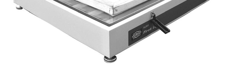
 to level unit front to back and side to side.")


12 First Light V Step 1 Place a level on unit s glass surface. Adjust leveling pads (1) to level unit front to back and side to side. Step 2 Feed the vacuum tube through the plastic anchor strap at the rear of the vacuum frame. Lightly pull on the plastic strap to secure the vacuum tube. Do not over tighten the plastic strap. Step 3 Connect the vacuum tube to the barbed hose fitting on the vacuum pump. Step 4 Connect the electric power cord from the vacuum pump to the receptacle marked VACUUM PUMP at the rear of the vacuum frame base. 12 M&R Companies 1N 372 Main St. Glen Ellyn, IL USA


 on the right of the digital display.")
13 V First Light 5. Operation Note: Your unit is shipped with 1 of 2 timers outlined in this chapter. Please refer to the instructions specific to your timer. 5.1 Control Panel (Timer Type A) Number Name Function 1 POWER ON/OFF The POWER ON/OFF switch turns electrical power ON or OFF to the unit. Switch 2 TIMER The TIMER is used to select the exposure time Setting the 24 Hour Clock Step 1 Note: Ensure power is applied to exposure unit. Press and hold the vertical bar (2) on the right of the digital display. Set the clock by turning the knob (3) until the correct time is displayed. Release the bar (2) and the pulsing red dot (1) between the hour and minutes indicates that the clock is operational. The current time (24-hour format) will be displayed whenever an exposure is not in progress. M&R Companies 1N 372 Main St. Glen Ellyn, IL USA 13
14 First Light V Control Panel UL (Timer Type B) Number Name Function 1 POWER ON/OFF The POWER ON/OFF switch turns electrical power ON or OFF to the unit. Switch 2 TIMER The TIMER is used to select the exposure time Setting the Clock Step 1 Note: Ensure power is applied to exposure unit. Press and hold the Set/Display button (1) for one second. The display (2) will default to 12:00 am and enter the Clock Set mode. While in the Clock Set mode the Mode, STOP and Start/Resume buttons are disabled and the Clock Set LED (3) will be turned On. Set the clock by pressing and holding the Increase (4) or Decrease (5) buttons until the correct time of day is displayed. The clock mode is a 12-hour with an am/pm indicator. When the clock displays a pm time the decimal point segment (6) is On. 14 M&R Companies 1N 372 Main St. Glen Ellyn, IL USA
15 V First Light To exit the Clock Set mode, press and hold the Set Display button (1) for one second. After one second a beeper will sound for one second confirming that the Clock Set mode has been exited. Once the clock is set, the display will go blank and the Clock Set LED (3) will turn Off. If the clock has been set and the Set Display button is pressed for less than one second, the display will show the current time for a five second period and then return to the previous display. 5.3 Making Screen Exposures Step 1 Unlatch the blanket frame assembly by pulling the bottom latch forward and up. Lift the top of the latch up and off the hook on the blanket frame. Step 2 Raise the blanket frame to the load/unload position. M&R Companies 1N 372 Main St. Glen Ellyn, IL USA 15


.")
16 First Light V Step 3 Center your film positive and screen frame on the glass work surface. Step 4 Place the bleeder cords on the screen as close to the edge as possible. DO NOT LAY THE BLEEDER CORDS ON THE IMAGE AREA. Step 5 Lower the blanket frame assembly and latch it by reversing the procedure described in Step 1. Step 6 Place the POWER switch in the ON position to start the vacuum pump. The blanket will now conform to the shape of the screen frame indicating that sufficient vacuum has been achieved. Step 7 Timer Type A Set the exposure time by turning the timer knob (1) clockwise. When the correct exposure time displays on the timer, start the exposure by pressing the START-STOP bar (2). Note: The timer has a repeat feature. Pressing the START-STOP bar after the exposure has ended will display the previous exposure setting. Pressing the START-STOP bar a second time starts the exposure sequence again. 16 M&R Companies 1N 372 Main St. Glen Ellyn, IL USA
 for one second. While holding down the Mode button, the mode will change every two seconds.")
17 V First Light Step 7 (Cont.) Timer Type B The timer features three countdown modes. Mode 1 range is 0-99 seconds. Mode 2 range is 0-99 minutes. Mode 3 range is 0-99 hours. Set the exposure time by pressing the Mode button (1) for one second. While holding down the Mode button, the mode will change every two seconds. As the mode changes the appropriate LED (2) for each mode will be turned On and the value displayed will change to the modes default time. An audible beep will also be heard. To set the exposure time, press the Increase (4) or Decrease (5) buttons until the proper countdown time is displayed. To start the exposure, press the Start/Resume button (6). You may stop the exposure by pressing the STOP button (7). The current time value will remain on the display. To resume the exposure, press the Start/Resume button (6) again. The exposure time will proceed from the point where stopped. Note: The timer has a repeat feature. Pressing the Start- Resume button (6) after the exposure has ended will display the previous exposure setting. Change the time value by pressing the Increase (4) or Decrease (5) buttons, or repeat the previous exposure by pressing the Start-Resume button (6) a second time. Step 8 After the exposure is complete, turn off the vacuum by moving the POWER switch to the OFF position. Unlatch the blanket frame assembly and slowly raise it to the load/unload position. Remove the film positive and screen. M&R Companies 1N 372 Main St. Glen Ellyn, IL USA 17
18 First Light V Scheduled Maintenance Benefits Preparation Properly maintained equipment operates more efficiently, reduces operating costs, and lasts longer. A properly managed preventive maintenance program can minimize downtime. An effective preventive maintenance program includes: proper selection, handling, and application of lubricants stocking high-quality replacement parts general cleaning and appearance of equipment creation of a preventive maintenance history for each piece of equipment Preventive maintenance documentation can be an invaluable resource. Frequency Maintenance WARNING: To prevent possible injury to personnel and/or damage to the equipment, lock out and tag the electrical service to the equipment. Daily Inspect and Clean Vacuum Blanket Inspect the vacuum blanket (1) for indications of photo emulsion residue, or other dirt and contaminants. Use a towel, moistened in warm tap water, to clean away any dirt or residue. Be sure to wipe dry the vacuum frame blanket. Clean Glass Items required: 1 Glass Cleaner Spray the glass surface (1) with glass cleaner and use a towel to wipe down. 18 M&R Companies 1N 372 Main St. Glen Ellyn, IL USA
19 V First Light Frequency Maintenance WARNING: To prevent possible injury to personnel and/or damage to the equipment, lock out and tag the electrical service to the equipment. Weekly Inspect Vacuum Hoses Inspect the vacuum hose (1) from the vacuum pump to the vacuum frame for any sign of twisting, kinking, or wear. Reposition vacuum hoses as needed to allow for efficient operation of the vacuum frame system. Replace any hoses which exhibit signs of wear or deterioration. M&R Companies 1N 372 Main St. Glen Ellyn, IL USA 19
 or Underwriters Laboratories (UL) standards, and each type of equipment has a")
20 First Light V Replacement Parts CE vs. UL Models All equipment containing electrical components is designed to comply with either Conformance European (CE) or Underwriters Laboratories (UL) standards, and each type of equipment has a different parts list. CE equipment runs at 50 Hz; UL equipment runs at 60 Hz. Electrical specifications, including Hertz, can be found on the Manufacturer s Rating Plate similar to the one shown below. Note: You must verify whether your equipment is 50 Hz (CE) or 60 Hz (UL) and order parts accordingly. DANGER: Operating this equipment with incorrect electrical parts can result in severe or fatal personal injuries and/or property damage. DANGER: When in operation, the Ballasts (Transformers) used on this equipment output high voltages that may cause serious injury or death. Each Ballast should only be connected or disconnected by a trained professional. Each Ballast is specially designed for maximum efficiency and longevity, to work in conjunction with lamps that are properly rated and manufactured to rigid specifications. Use of lamps from other resources may damage the Ballasts, and/or void the M&R Limited Warranty. Schematic Diagrams for Electrical Parts Ozone and Rubber Products M&R uses the just-in-time approach to printing manuals, so the electrical parts and part numbers shown in this section should be accurate. However, since schematic diagrams are unit-specific, they remain the most accurate source of electrical part numbers. Cross-reference the part numbers in this manual with the part numbers in the schematic diagrams in the back of this manual before placing an order. All of the vacuum blankets manufactured by NuArc Company., Inc. for the Screen Printing Industry are made of rubber products. These rubber products are damaged by exposure to higher levels of ozone. Any blanket returned to NuArc that shows indications of damage due to exposure to ozone will not be replaced or credited in any way under the warranty. Ozone occurring naturally in the atmosphere will not damage blankets to any noticeable degree. However, the ozone produced by some electronic air purifying units is concentrated enough to cause significant damage to vacuum blankets. Do not use ozone producing air purifiers of any type in any position that would cause the vacuum blanket to become exposed to increased levels of ozone. 20 M&R Companies 1N 372 Main St. Glen Ellyn, IL USA
21 V First Light Control Panel (UL & CE) Control Panel (Timer Type B) (UL & CE) Part Name Part Numbers First Light 1 ON/OFF Switch VE Timer 115V, 60 Hz 9N Timer 240V, 50/60 Hz 9N M&R Companies 1N 372 Main St. Glen Ellyn, IL USA 21
 Chassis and Lamp")

 VE1221 22")
22 First Light V Chassis and Lamp Assembly (UL & CE) Chassis and Lamp Assembly (UL & CE) Part Name Part Numbers First Light 1 Lift Arm PR10 2 Blanket 9N Black Light Fluorescent Lamp 30W VE Lamp Holder VE Glass 9N Leg Equalizer Glide VH Latch VH982 8 Lamp Ballast (Not Shown) VE M&R Companies 1N 372 Main St. Glen Ellyn, IL USA


23 V First Light Vacuum Pump (UL & CE) Vacuum Pump (UL & CE) Part Name Part Numbers First Light 1 Vacuum Pump 120V, 60 Hz VE1215 Vacuum Pump 220V, 50/60 Hz VE Pipe Tee 1/4" VE123 3 Vacuum Relief Valve VH Rubber Bumper VH158 5 Rubber Tubing 1/4" ID VH124 M&R Companies 1N 372 Main St. Glen Ellyn, IL USA 23
Tube Rotator. User Guide. Version 1.2
 Tube Rotator User Guide Version 1.2 Figure 1: Fixed Speed Model Tube holder spindle Tilt adjustment wheel IEC power inlet socket (at rear) Power on/off switch Figure 2: Variable Speed Model Tube holder
Operation Manual VMS 3.0 Video System
 Operation Manual VMS 3.0 Video System for the AlterG Anti-Gravity Treadmill 1 This manual covers operation procedures for the following AlterG products: AlterG Video System model VMS 3.0 NOTE: The following
INSTRUCTION BOOK FOR. Fast-Fold NXT
 INSTRUCTION BOOK FOR Fast-Fold NXT Disclaimer Milestone and its affiliated corporations and subsidiaries (collectively "Milestone"), intend to make this manual accurate and complete. However, Milestone
TV Lift System Model CL-65 Installation Instructions
 TV Lift System Model CL-65 Installation Instructions Contact: Support@Nexus21.com Toll Free: (866) 500-5438 Phone: (480) 951-6885 Fax: (480) 951-6879 Revised: 01/17/17 Below is a parts list describing
 www.greenelectricalsupply.com MaxLite 6 & 8 Commercial Downlight Retrofit General Safety Information To reduce the risk of death, personal injury or property damage from fire, electric shock, falling parts,
AB CRUNCH SIT UP BENCH MODEL# 8642AB PRODUCT MANUAL - VERSION
 AB CRUNCH SIT UP BENCH MODEL# 842AB PRODUCT MANUAL - VERSION 01.18.0 FOR AGES: WEIGHT LIMIT: 20 Lbs 3 Kgs TO BUILD: 13+ 1 X TOOLS NEEDED: CUSTOMER SERVICE GQBrands.com CustomerService@GQBrands.com 1-8-498-29
APSPB PUSH BUTTON ZERO Installation Manual
 APSPB PUSH BUTTON ZERO Installation Manual CARDINAL SCALE MFG. CO. 8527-0579-0M Rev A 203 E. Daugherty, Webb City, MO 64870 USA Printed in USA 12/14 Ph: 417-673-4631 Fax: 417-673-2153 www.detectoscale.com
EN - English Washington Street Melrose, MA Phone Toll Free Revision 4 20/06/17
 - English... 1 Instruction Manual Vortex Mixer, Mini Fix Speed, VXMNFS Vortex Mixer, Mini Analog, VXMNAL Vortex Mixer, Mini Digital, VXMNDG Vortex Mixer, Mini Pulsing, VXMNPS 99 Washington Street Melrose,
INSTRUCTION BOOK FOR. Lectern
 INSTRUCTION BOOK FOR Lectern Disclaimer Milestone and its affiliated corporations and subsidiaries (collectively "Milestone"), intend to make this manual accurate and complete. However, Milestone makes
Website: Tel: ADDRESS: 6475 Las Positas Rd. Livermore, CA Item No. E5B/E5S Installation Guide
 Website: www.flexispot.com Tel: -855-4-808 ADDRESS: 6475 Las Positas Rd. Livermore, CA 9455 Item No. E5B/E5S Installation Guide Specifications Step Column 3 Max. Weight Capacity 0 Ibs (00 kg) Speed 38mm/s
User Instructions. 16 SCB Sync Station.
 User Instructions 16 SCB Sync Station Contents Overview... 1 Specifications... 1 Compliance and approvals... 2 Safety instructions... 3 Set up... 4 How to charge multiple devices... 4 How to synchronize
3G/HD/SD-SDI to HDMI Converter
 3G/HD/SD-SDI to HDMI Converter Model #: 3G/HD/SD-SDI to HDMI Converter 2010 Avenview Inc. All rights reserved. The contents of this document are provided in connection with Avenview Inc. ( Avenview ) products.
Tube Roller Shakers. User Guide. Version 1.2
 Tube Roller Shakers User Guide Version 1.2 Control panel Rollers Side retaining panels Analog models LED display Drip tray (not visible) Digital models Power On/Off and control dial Roller retaining panel
1X4 HDMI Splitter with 3D Support
 AV Connectivity, Distribution And Beyond... VIDEO WALLS VIDEO PROCESSORS VIDEO MATRIX SWITCHES EXTENDERS SPLITTERS WIRELESS CABLES & ACCESSORIES 1X4 HDMI Splitter with 3D Support Model #: SPLIT-HDM3D-4
Circulating Feed Delivery System Installation Instructions for Model 55, 75, 90, & HMC FLEX-AUGER Feed Delivery Systems
 Circulating Feed Delivery System Installation Instructions for Model 55, 75, 90, & HMC FLEX-AUGER Feed Delivery Systems April 02 Chore-Time Warranty Chore-Time Equipment, a division of CTB, Inc., ("Chore-Time")
Winch Adjustable Feed Level Tubes for the Adult Turkey Feeder Installation & Operator s Instruction Manual MF /99
 Winch Adjustable Feed Level Tubes for the Adult Turkey Feeder Installation & Operator s Instruction Manual MF7-8 6/99 June 999 MF7B Chore-Time Warranty Winch Adjustable Feed Level Tubes for ATF Chore-Time
SINCE User Manual 7 DAY PROGRAMMABLE DIGITAL TIMER MODEL PS-100. The best solutions for automation and protection.
 SINCE 1973 User Manual 7 DAY PROGRAMMABLE DIGITAL TIMER MODEL PS-100 The best solutions for automation and protection www.nassarelectronics.com Description The PS-100 is a 7 day programmable digital timer
5 Port DVI Splitter VIDEO WALLS VIDEO PROCESSORS VIDEO MATRIX SWITCHES EXTENDERS SPLITTERS WIRELESS CABLES & ACCESSORIES
 AV Connectivity, Distribution And Beyond... VIDEO WALLS VIDEO PROCESSORS VIDEO MATRIX SWITCHES EXTENDERS SPLITTERS WIRELESS CABLES & ACCESSORIES 5 Port DVI Splitter Model #: SPLIT-DVI-5 2013 Avenview Inc.
Circulating Feed Delivery System Installation Instructions for Model 55, 75, 90, & HMC FLEX-AUGER Feed Delivery Systems
 Circulating Feed Delivery System Installation Instructions for Model 55, 75, 90, & HMC FLEX-AUGER Feed Delivery Systems MA773-06 5/99 May 1999 Chore-Time Warranty Chore-Time Equipment warrants each new
Utility Amplifier GA6A Model
 Utility Amplifier GA6A Model Installation and Use Manual 2004 Bogen Communications, Inc. All rights reserved. Specifications subject to change without notice. 54-5757-03D 1503 NOTICE: Every effort was
OPERATION AND MAINTENANCE MANUAL
 OPERATION AND MAINTENANCE MANUAL SERIAL NUMBER CUSTOMER: SALES REP.: CONTENTS Mixer Installation / Assembly / Dimension Drawings Safety... 1 Customer Service Contact... 1 Initial Inspection... 2 Installation...2
MWT-FM. Operation Manual. FM Single Channel Transmitter. man_mwtfm.
 MWT-FM FM Single Channel Transmitter Operation Manual man_mwtfm www.myeclubtv.com CONTENTS FCC COMPLIANCE STATEMENT. 3 INDUSTRY CANADA COMPLIANCE 3 MWT-FM ORIENTATION. 4 SAFETY PRECAUTIONS 5 FINDING FM
Golf ball tracker. Instruction manual
 Golf ball tracker Instruction manual General Intended use The Prazza golf ball finder is intended for use on the golf course only and should never be used inside the home or any other enclosed environment.the
SyncGen. User s Manual
 SyncGen User s Manual 1 IMPORTANT SAFETY INSTRUCTION READ FIRST This symbol, whenever it appears, alerts you to the presence of uninsulated dangerous voltage inside the enclosure-voltage that may be sufficient
CVSB/ S-video/ HDMI to HDMI Scaler with 720p and 1080p Switching.
 CVSB/ S-video/ HDMI to HDMI Scaler with 720p and 1080p Switching. Model #: C-CVID-HDM 2012 Avenview Inc. All rights reserved. The contents of this document are provided in connection with Avenview Inc.
INSTRUCTION MANUAL. ANI-1x2COMPDA. 1x2 Component Video(RCA) Splitter Distribution Amplifier w/ Digital Coaxial/Optical Audio
 Splitter Distribution Amplifier w/ Digital Coaxial/Optical Audio") ANI-1x2COMPDA INSTRUCTION MANUAL 1x2 Component Video(RCA) Splitter Distribution Amplifier w/ Digital Coaxial/Optical Audio A-NeuVideo.com Frisco, Texas 75034 (469) 277-7606 AUDIO / VIDEO MANUFACTURER SAFETY
ANI-1x2COMPDA INSTRUCTION MANUAL 1x2 Component Video(RCA) Splitter Distribution Amplifier w/ Digital Coaxial/Optical Audio A-NeuVideo.com Frisco, Texas 75034 (469) 277-7606 AUDIO / VIDEO MANUFACTURER SAFETY
English. User Manual sub8 Subwoofer SUBWOOFER. Supporting your digital lifestyle
 English User Manual sub8 Subwoofer U SUBWOOFER Supporting your digital lifestyle Table of Contents Important Safety Precautions........ 2 Introduction / What s in the Box?...... 3 Front & Rear Panels............
8 Port HD/SD-SDI Switch
 8 Port HD/SD-SDI Switch User s Guide Models SW-HDSDI-8X1 2008 Avenview Inc. All rights reserved. The contents of this document are provided in connection with Avenview Inc. ( Avenview ) products. Avenview
Quintet SL. Owner s Manual
 Quintet SL Owner s Manual QUINTET SL SPEAKER SYSTEM IMPORTANT SAFETY INSTRUCTIONS 1. READ these instructions. 2. KEEP these instructions. 3. HEED all warnings. 4. FOLLOW all instructions. 5. DO NOT use
VideoSplitter HDMI 4K PT
 VideoSplitter HDMI 4K PT 4K HDMI Splitter Pigtail Type Installation and Operation Manual 10707 Stancliff Road Houston, Texas 77099 Phone: (281) 933-7673 tech-support@rose.com LIMITED WARRANTY Rose Electronics
Instant 802.3af Gigabit Outdoor PoE Converter. Model: INS-3AF-O-G. Quick Start Guide
 Instant 802.3af Gigabit Outdoor PoE Converter Model: INS-3AF-O-G Quick Start Guide QUICK START GUIDE Introduction Thank you for purchasing the Ubiquiti Networks Instant 802.3af Gigabit Outdoor PoE Converter.
Installation Manual SaVi Note Underwater LED Light
 Installation Manual SaVi Note Underwater LED Light Model Numbers SAVI-NOTE7, SAVI-NOTE0 Table of Contents Safety Precautions...2 SaVi Note Install Instructions...3- M Instructions...- Warnings READ AND
CHECK LINE. Model LS-36-LED. Stationary Stroboscope. Operating Manual BY ELECTROMATIC
 CHECK LINE BY ELECTROMATIC Stationary Stroboscope Model LS-36-LED Operating Manual Table of Contents 1.0 Introduction... 02 1.1 Unpacking 1.2 Optional Accessories 2.0 Safety Information... 3 3.0 Controls...
Contents. Instruction Manual T-Rex Page 2 of 16 Release 1.01
 Contents 1 Safety Precautions... 3 2 Introduction:... 5 3 Theory of Operation... 7 4 Unpacking Procedure... 8 5 Operating TR-Mark III with T-Rex... 9 6 Operating a TR-Mark II with a T-Rex... 13 7 Technical
Children cannot always recognize potential hazards properly. This 5.1 system is not designed for operation in a heavy industry environment.
 5.1 FLAT PANEL SPEAKER SYSTEM WITH POWERED SUBWOOFER Table of Contents: SAFETY AND SERVICE... 2 Operational Safety... 2 Location... 2 Ambient Temperature... 3 Electromagnetic Compliance... 3 Service...
DVDO VS4 HDMI Switch. User s Guide How to install, set up, and use your new DVDO product
 DVDO VS4 HDMI Switch User s Guide How to install, set up, and use your new DVDO product TABLE OF CONTENTS Table of Contents... 1 Introduction... 1 Installation and Set-Up... 2 Remote Control Operation...
INSTRUCTION MANUAL SUPER LASER
 INSTRUCTION MANUAL SUPER LASER WARNINGS When using this SUPER LASER, basic safety precautions should always be followed to reduce the risk of fire, electric shock, and personal injury. Follow the instructions
Instruction Manual Fixed Speed Vortex Mixer Analog Vortex Mixer Digital Vortex Mixer Pulsing Vortex Mixer
 Instruction Manual Fixed Speed Vortex Mixer Analog Vortex Mixer Digital Vortex Mixer Pulsing Vortex Mixer Table of Contents Package Contents............ 1 Warranty............ 1 Installation............
CAUTION RISK OF ELECTRIC SHOCK NO NOT OPEN
 Evolution Digital HD Set-Top Box Important Safety Instructions 1. Read these instructions. 2. Keep these instructions. 3. Heed all warnings. 4. Follow all instructions. 5. Do not use this apparatus near
WID-DL74 WID-DL74 BLP WID. Designed for. Installation guide for workitdesk interactive table for. BrightLink Pro
 WID-DL74 WID-DL74 BLP WID Designed for BrightLink Pro Installation guide for workitdesk interactive table BrightLink Pro for Mounting the table unit 1 Unpack boxes 1 of 4 (Mobile base) and 2 of 4 (Motorized
MIRAGE. Skyline Mirage Set-Up Instructions Skyline Exhibits
 MIRAGE Skyline Mirage Set-Up Instructions www.skyline.com Table of Contents Mirage Pop-up is available in many sizes from 32 tall tabletops to 92 tall backwalls. The following set-up and repacking instructions
Connevans.info. DeafEquipment.co.uk. This product may be purchased from Connevans Limited secure online store at
 Connevans.info Solutions to improve the quality of life Offering you choice Helping you choose This product may be purchased from Connevans Limited secure online store at www.deafequipment.co.uk DeafEquipment.co.uk
VGA & RS232 Extender SET over Single CAT5 with RGB Delay Control
 VGA & RS232 Extender SET over Single CAT5 with RGB Delay Control Model #: VGA-C5RS-SET 2010 Avenview Inc. All rights reserved. The contents of this document are provided in connection with Avenview Inc.
VGA & Audio Receiver SET over Single CAT5 with RGB Delay Control
 VGA & Audio Receiver SET over Single CAT5 with RGB Delay Control Model #: VGA-C5A-R 2010 Avenview Inc. All rights reserved. The contents of this document are provided in connection with Avenview Inc. (
Manual No: Revision: D. IQ Box. Software Upgrade Instructions
 Manual No: 577013-834 Revision: D IQ Box Software Upgrade Instructions Notice Veeder-Root makes no warranty of any kind with regard to this publication, including, but not limited to, the implied warranties
Installation Manual Original Instructions - IW4001
 Installation Manual Original Instructions - IW4001 Installation Manual 1 General Operator and Supervisor Information Signal Word Definition Signal Word Panel Table of Contents Operator and Supervisor Information
Thank you for purchasing SEIKO SHOOTING TIMER KT-401. Before using your SEIKO SHOOTING TIMER, please read this manual carefully for its proper use
 紙 Thank you for purchasing SEIKO SHOOTING TIMER KT-401. Before using your SEIKO SHOOTING TIMER, please read this manual carefully for its proper use and care. Keep this manual handy for ready reference.
User Guide. Single-Link DVI Active Cable Extender. DVI-7171c
 User Guide Single-Link DVI Active Cable Extender DVI-7171c TABLE OF CONTENTS SECTION PAGE PRODUCT SAFETY...1 PRODUCT LIABILITY...1 1.0 INTRODUCTION...2 2.0 SPECIFICATIONS...3 3.0 PACKAGE CONTENTS...4 4.0
Basic Vortex Mixer Standard Vortex Mixer Advanced Vortex Mixer Pulsing Vortex Mixer
 Instruction Manual Manual Basic Vortex Mixer Standard Vortex Mixer Advanced Vortex Mixer Pulsing Vortex Mixer Table of Contents Package Contents............... 1 Warranty............... 1 Installation...............
8 Port HD/SD-SDI Video Switch with 2 Port Splitter
 8 Port HD/SD-SDI Video Switch with 2 Port Splitter User s Guide Models SW-HDSDI-8X2 2008 Avenview Inc. All rights reserved. The contents of this document are provided in connection with Avenview Inc. (
Magnetic Field Generator 1000
 Magnetic Field Generator 1000 User Manual 1 (14) Magnetic Field Generator 1000 User Manual 1.0 Getting Started: Unpacking, Installation and Safety Inspect the instrument for any damage caused by shipping.
Information. Marketing Description. For Models: DA2133i. 2113i. User s Guide Rev B
 Casework Model Number User s Marketing Description Information For Models: xxxx FCC (-001) (All) xxxx FTC (All) (-002) DA2133i 2113i User s Guide 003-1891-00 Rev B Table of Contents Important Information
Qianglong Furniture Co., Ltd.
 Qianglong Furniture Co., Ltd. ITEM NO.: 400-12-00K Gaming Chair manual THIS INSTRUCTION BOOKLET CONTAINS IMPORTANT SAFETY INFORMATION. PLEASE READ AND KEEP FOR FUTURE REFERENCE. DO NOT RETURN TO THE STORE
TO THE INSTALLER: BE SURE TO LEAVE THIS MANUAL WITH THE OWNER.
 Fixed Frame Screen Owner s Manual To the Owner Installation Instructions Screen Care CFS-010517 Maintenance TO THE INSTALLER: BE SURE TO LEAVE THIS MANUAL WITH THE OWNER. Printed in U.S.A. Stewart Filmscreen
Install Guide Incredible Technologies, Inc. All Rights Reserved
 Install Guide 2015 Incredible Technologies, Inc. All Rights Reserved Preface Using this Guide The following icons are used to highlight specific areas of interest and to indicate when extreme caution is
DisplayPort to VGA Converter
 DisplayPort to VGA Converter Model #: C-DP-VGA 2010 Avenview Inc. All rights reserved. The contents of this document are provided in connection with Avenview Inc. ( Avenview ) products. Avenview makes
DIGITAL TIME CLOCK. used with the Meal-Time Control Panel. AGRI-TIME TM Control Instruction Page 1
 TM AGRI- DIGITAL CLOCK used with the 34385 Meal-Time Control Panel MF1116A12 May 1995 Page 1 Warranty Information Chore-Time Equipment warrants each new product manufactured by it to be free from defects
USER MANUAL Table of Contents
 USER MANUA Table of Contents Safety Information. 3 Specifications.. 4 Main Power Connection.. 5 DMX-512 Connection...... 5 DMX Profile... 7 Main Control Menu... 8 Rigging the Fixture.10 Cleaning & Maintenance...10
Z100 / Z300 Z500 Z700 OWNER S MANUAL PLEASE CAREFULLY READ THIS ENTIRE MANUAL BEFORE OPERATING YOUR NEW ELLIPTICAL!
 Z100 / Z300 Z500 Z700 OWNER S MANUAL PLEASE CAREFULLY READ THIS ENTIRE MANUAL BEFORE OPERATING YOUR NEW ELLIPTICAL! Table of Contents Product Registration. 2 Important Safety Instructions 3 Important Electrical
VGA, Audio & RS232 Extender SET over Single CAT5 with RGB Delay Control & IR Pass Through
 VGA, Audio & RS232 Extender SET over Single CAT5 with RGB Delay Control & IR Pass Through Model #: VGA-C5ARS-SET 2010 Avenview Inc. All rights reserved. The contents of this document are provided in connection
Master Time Clock MTC Users Manual
 Master Time Clock MTC-6000 Users Manual Midwest Time Control Phone (972)987-4408 Toll Free (888)713-0373 FAX (877)720-9291 www.midwest-time.com sales@midwest-time.com TABLE OF CONTENTS TOPIC PAGE GENERAL
Design and Manufacture of Video Pipeline Inspection Systems A Full Service Company
 Design and Manufacture of Video Pipeline Inspection Systems A Full Service Company www.rstechserv.com 1315 Controller OPERATIONS MANUAL Made in the USA Table Of Contents: Page 3 Page 5 Page 6 Page 7 Page
Keysight 16048G/H Test Leads
 Keysight 16048G/H Test Leads Operation and Service Manual Notices The information contained in this document is subject to change without notice. This document contains proprietary information that is
VGA / Audio Extender Single CAT5 / CAT6 with RGB Delay Control & EQ
 VGA / Audio Extender Single CAT5 / CAT6 with RGB Delay Control & EQ Model #: VGA-C5A-SET 2010 Avenview Inc. All rights reserved. The contents of this document are provided in connection with Avenview Inc.
VGAD-12 ORDERCODE
 VGAD-12 ORDERCODE 101220 Congratulations! You have bought a great, innovative product from DMT. The DMT Media Spinner brings excitement to any venue. Whether you want simple plug-&-play action or a sophisticated
AUTOMATIC TAPING MACHINE INSTRUCTION MANUAL TAIYO SEIKI CO., LTD.
 - AUTOMATIC TAPING MACHINE INSTRUCTION MANUAL TAIYO SEIKI CO., LTD. 1 Contents CONTENTS 1. Introduction... 2 1-1. Important safety notice...2 1-2. Precautions for use and installation...2 1-3. Operating
LIGHT COPILOT II. elationlighting.com Internet:
 LIGHT COPILOT II E-mail: info@ elationlighting.com Internet: http://www.elationlighting.com 1 Introduction Thank you for your purchase of the LIGHT COPILOT II. The LIGHT COPILOT II is an intelligent lighting
INSTRUCTION MANUAL MUSICAL LASER LIGHT SHOW TM
 INSTRUCTION MANUAL MUSICAL LASER LIGHT SHOW TM WARNINGS When using this MUSICAL LASER LIGHT SHOW TM, basic safety precautions should always be followed to reduce the risk of fire, electric shock, and personal
SCRIPT INNOVATIONS C- RAY PILL COUNTER OPERATORS MANUAL
 SCRIPT INNOVATIONS C- RAY PILL COUNTER OPERATORS MANUAL VERSION 2.0 Providers of Enhanced Pharmaceutical Equipment FCC Statement This device complies with part 15 of the FCC Rules. Operation is subject
MP-7424 Football Scoreboard with MP5000 Console
 MP-7424 Football Scoreboard with MP5000 Console With additional instructions for Track and Soccer Operator s Manual Volume VII Rev. 10/17/07 Table of Contents Table of Contents...2 1.0 Keypad Console...3
Installation and Operation Manual
 PROBLEM SOLVED Installation and Operation Manual INC AES DA 2x6 Six-output, two-input AES/EBU Digital Audio Distribution Amplifier Manual update: 9/17/2015 If you need a firmware upgrade, contact Broadcast
HDMI 1.3 Receiver over Signal. CAT5/CAT6 Cable. Model #: HDMI-C5-R-M. 1
 HDMI 1.3 Receiver over Signal CAT5/CAT6 Cable Model #: HDMI-C5-R-M 2010 Avenview Inc. All rights reserved. The contents of this document are provided in connection with Avenview Inc. ( Avenview ) products.
Evolution Digital HD Set-Top Box Important Safety Instructions
 Evolution Digital HD Set-Top Box Important Safety Instructions 1. Read these instructions. 2. Keep these instructions. 3. Heed all warnings. 4. Follow all instructions. 5. Do not use this apparatus near
User s Manual. Squirrelly Adventure Tree House TM VTech All rights reserved Printed in China US
 User s Manual Squirrelly Adventure Tree House TM 2017 VTech All rights reserved Printed in China 91-003309-000 US M INTRODUCTION Thank you for purchasing the VTech Go! Go! Smart Animals Squirrelly Adventure
K Service Source. Apple High-Res Monochrome Monitor
 K Service Source Apple High-Res Monochrome Monitor K Service Source Specifications Apple High-Resolution Monochrome Monitor Specifications Characteristics - 1 Characteristics Picture Tube 12-in. diagonal
CYBER PAK. User Instructions.
 CYBER PAK User Instructions www.elationlighting.com 2016 ELATION PROFESSIONAL all rights reserved. Information, specifications, diagrams, images, and instructions herein are subject to change without notice.
Sprite TL Quick Start Guide
 Sprite TL Quick Start Guide with 115 VAC Power Cord and 4-Conductor Signal Cable Reference Manual Sprite TL Online and downloadable Product Manuals and Quick Start Guides are available at www.hydrosystemsco.com
Mini Electronic Pulse Massager
 Mini Electronic Pulse Massager UC-029 Operating Manual Contents Introduction...2 Safety warnings....3 Part identification 4 Operating instructions...5 Program schematics....6-8 Recommended use points......8
Instructions. P MHz 1X/10X Passive Probe
 Instructions P2100 100 MHz 1X/10X Passive Probe 071-0774-01 071077401 Copyright Tektronix, Inc. All rights reserved. Tektronix products are covered by U.S. and foreign patents, issued and pending. Information
In-Line or 75 Ohm In-Line
 or 5 Ohm 1dB Adjustable Gain 800/1900 Smart Technology Contents: Quick Install Overview.... 2 Installation Diagram.... Understanding the Lights... 9 Warnings and Recommendations....11 Appearance of device
K Service Source. Apple High-Res Monochrome Monitor
 K Service Source Apple High-Res Monochrome Monitor K Service Source Specifications Apple High-Resolution Monochrome Monitor Specifications Characteristics - 1 Characteristics Picture Tube 12-in. diagonal
*Prefer. 600 MHz 4K ULTRA. 60Hz, 4:4:4. over one SC-Terminated Fiber-Optic Cable EXT-DP-4K600-1SC. User Manual. Release A1
 *Prefer 600 MHz 4K ULTRA 60Hz, 4:4:4 DisplayPort 1.2 Extender over one SC-Terminated Fiber-Optic Cable EXT-DP-4K600-1SC User Manual Release A1 Important Safety Instructions 1. Read these instructions.
ezcinema Plus Series
 ezcinema Plus Series Portable Floor Pull-Up USER S GUIDE Rev062510-JA www.elitescreens.com info@elitescreens.com Precautions: Warning! damage can result from operational errors if the enclosed precautions
MASTR II BASE STATION 12/24V POWER SUPPLY 19A149979P1-120 VOLT/60 Hz 19A149979P2-230 VOLT/50 Hz
 Mobile Communications MASTR II BASE STATION 12/24V POWER SUPPLY 19A149979P1-120 VOLT/60 Hz 19A149979P2-230 VOLT/50 Hz CAUTION THESE SERVICING INSTRUCTIONS ARE FOR USE BY QUALI- FIED PERSONNEL ONLY. TO
TR6102HD HDTV/DVD/COMPONENT VIDEO TO RGBHV TRANSCODER USER S GUIDE
 MANUAL PART NUMBER: 400-0031-003 PRODUCT REVISION: 1 HDTV/DVD/COMPONENT VIDEO TO RGBHV TRANSCODER USER S GUIDE INTRODUCTION Thank you for your purchase of the Transcoder. We are certain that you will find
User Manual. AtlonA. Passive VGA Extender with Wall Plate or Box options up to 330ft over 1 x CAT5/6/7 Cable AT-VGA100-SR and AT-WPVGA-SR AT-WPVGA-SR
 User Manual AtlonA Passive VGA Extender with Wall Plate or Box options up to 330ft over 1 x CAT5/6/7 Cable AT-VGA100-SR and AT-WPVGA-SR AT-WPVGA-SR Receiver Transmitter AT-VGA100-SR Receiver Transmitter
Tripod Portable Projection Screen Elite Tripod Series
 Tripod Portable Projection Screen Elite Tripod Series USER S GUIDE Rev. 060809-JA www.elitescreens.com info@elitescreens.com Tripod Screen Parts Identification Support beam Top Hook, Keystone Eliminator
OWNER S MANUAL. Model 861 Hand Held Bale Scanner # REVISED 4-10
 OWNER S MANUAL Model 861 Hand Held Bale Scanner #010-0861 REVISED 4-10 HARVEST TEC 861 TABLE OF CONTENTS PAGE INTRODUCTION 3 OVERVIEW 4 INSTALLATION OF ANTENNA 5 1. INSTALLATION OF ANTENNA FOR HAND HELD
FogScreen emotion Projection Screen. User Manual Part 1: Installation Guidelines
 FogScreen emotion Projection Screen User Manual Part 1: Installation Guidelines NOTE: All users of FogScreen projection screen must read and understand these instructions before installation or operation
4, 8, 16 Port VGA and Audio Extender / Splitter with Audio over Single CAT5
 4, 8, 16 Port VGA and Audio Extender / Splitter with Audio over Single CAT5 Model #: VGA-C5SP-4, VGA-C5SP-8, VGA-C5SP-16 2010 Avenview Inc. All rights reserved. The contents of this document are provided
USER MANUAL. WARNING Read the instructions before using the machine. EN (Original Instruction) / 1704
 / 1704") USER MANUAL European Models American Models 60/100/120 3/4/5 24/40/48 3/4/5 Read the instructions before using the machine. EN (Original Instruction) 9124097 / 1704 KEEP THIS USER MANUAL FOR FUTURE USE
USER MANUAL European Models American Models 60/100/120 3/4/5 24/40/48 3/4/5 Read the instructions before using the machine. EN (Original Instruction) 9124097 / 1704 KEEP THIS USER MANUAL FOR FUTURE USE
VGA to DVI Extender over Fiber SET
 VGA to DVI Extender over Fiber SET Model #: FO-VGA-DVI 2011 Avenview Inc. All rights reserved. The contents of this document are provided in connection with Avenview Inc. ( Avenview ) products. Avenview
SpectraPulse Ultra Wideband Wireless Microphone System
 SpectraPulse Ultra Wideband Wireless Microphone System rcu104 Receiver Coordinator Unit rcu104 RECEIVER COORDINATOR UNIT POWER ON OFF DRM1 DRM2 DRM3 DRM4 s p e c t r a p u l s e Set-up and Operation 2
Enable-IT 821P PoE Extender Quickstart Guide Professional Grade Networking
 ! Enable-IT 821P PoE Extender Quickstart Guide Professional Grade Networking All Rights Reserved 1997-2016 Enable-IT, Inc. INSTALLING THE 821P POE EXTENDER The Enable-IT 821P PoE Extenders have a distance
HIIT Console OWNER S MANUAL
 HIIT Console OWNER S MANUAL IMPORTANT SAFETY INSTRUCTIONS CONSOLE SAFETY INSTRUCTIONS All connected products/equipment are for fitness and health purposes only. Any readings/values should not be used for
Installation Operation Maintenance
 Installation Operation Maintenance Rooftop Energy Recovery Module for TKD / TKH / WKD / WKH YKD / YKH / DKD / DKH # 125-155-175-200 250 265-290-340 # 275-300-350-400-500-600 April 2011 RT-SVX42B-E4 General
INSTRUCTION BOOK FOR. Deluxe Insta-Theater
 INSTRUCTION BOOK FOR Deluxe Insta-Theater Introduction Thank you for purchasing this Da-Lite product. Before attempting to use it, make sure to carefully read the contents of these instructions. Caution
MYE TV Audio Grabber
 Radio MYE TV Audio Grabber Model: MAG98 Operation Manual Man_MAG_V2 www.myeclubtv.com FCC Compliance Statement NOTE: This equipment has been tested and found to comply with the limits for a class B digital
Table of Contents. Introduction Pin Description Absolute Maximum Rating Electrical Specifications... 4
 Table of Contents Introduction... 1 Pin Description... 2 Absolute Maximum Rating... 3 Electrical Specifications... 4 Mechanical Specifications... 5 Thermal Specifications... 6 Over Temperature Protection...
HD Digital Set-Top Box Quick Start Guide
 HD Digital Set-Top Box Quick Start Guide Eagle Communications HD Digital Set-Top Box Important Safety Instructions WARNING TO REDUCE THE RISK OF FIRE OR ELECTRIC SHOCK, DO NOT EXPOSE THIS PRODUCT TO RAIN