4CH/2 CH Digital Storage Oscilloscopes Mixed Signal Oscilloscopes
|
|
|
- Carol Perkins
- 5 years ago
- Views:
Transcription

1 Series: CH/2 CH Digital Storage Oscilloscopes Mixed Signal Oscilloscopes USER MANUAL
2 Safety Summary The following safety precautions apply to both operating and maintenance personnel and must be followed during all phases of operation, service, and repair of this instrument. Before applying power to this instrument: Read and understand the safety and operational information in this manual. Apply all the listed safety precautions. Verify that the voltage selector at the line power cord input is set to the correct line voltage. Operating the instrument at an incorrect line voltage will void the warranty. Make all connections to the instrument before applying power. Do not operate the instrument in ways not specified by this manual or by B&K Precision. Failure to comply with these precautions or with warnings elsewhere in this manual violates the safety standards of design, manufacture, and intended use of the instrument. B&K Precision assumes no liability for a customer s failure to comply with these requirements. Category rating The IEC standard defines safety category ratings that specify the amount of electrical energy available and the voltage impulses that may occur on electrical conductors associated with these category ratings. The category rating is a Roman numeral of I, II, III, or IV. This rating is also accompanied by a maximum voltage of the circuit to be tested, which defines the voltage impulses expected and required insulation clearances. These categories are: Category I (CAT I): Measurement instruments whose measurement inputs are not intended to be connected to the mains supply. The voltages in the environment are typically derived from a limited-energy transformer or a battery. Category II (CAT II): Measurement instruments whose measurement inputs are meant to be connected to the mains supply at a standard wall outlet or similar sources. Example measurement environments are portable tools and household appliances. Category III (CAT III): Measurement instruments whose measurement inputs are meant to be connected to the mains installation of a building. Examples are measurements inside a building's circuit breaker panel or the wiring of permanently-installed motors. Category IV (CAT IV): Measurement instruments whose measurement inputs are meant to be connected to the primary power entering a building or other outdoor wiring. Measurement Categories These digital oscilloscopes can make measurements in measurement category I (CAT I). Do not exceed a voltage input of more than 5 V absolute value for a 50 Ω impedance input or 400 V absolute value for a 1 MΩ impedance input. i
3 This oscilloscope can only be used for measurements within its specified measurement category. Do not use this instrument in an electrical environment with a higher category rating than what is specified in this manual for this instrument. You must ensure that each accessory you use with this instrument has a category rating equal to or higher than the instrument's category rating to maintain the instrument's category rating. Failure to do so will lower the category rating of the measuring system. Electrical Power This instrument is intended to be powered from a CATEGORY II mains power environment. The mains power should be 120 V RMS or 240 V RMS. Use only the power cord supplied with the instrument and ensure it is appropriate for your country of use. Ground the Instrument To minimize shock hazard, the instrument chassis and cabinet must be connected to an electrical safety ground. This instrument is grounded through the ground conductor of the supplied threeconductor AC line power cable. The power cable must be plugged into an approved threeconductor electrical outlet. The power jack and mating plug of the power cable meet IEC safety standards. Do not alter or defeat the ground connection. Without the safety ground connection, all accessible conductive parts (including control knobs) may provide an electric shock. Failure to use a properlygrounded approved outlet and the recommended three-conductor AC line power cable may result in injury or death. Unless otherwise stated, a ground connection on the instrument's front or rear panel is for a reference of potential only and is not to be used as a safety ground. Do not operate in an explosive or flammable atmosphere. Do not operate the instrument in the presence of flammable gases or vapors, fumes, or finelydivided particulates. ii
4 The instrument is designed to be used in office-type indoor environments. Do not operate the instrument In the presence of noxious, corrosive, or flammable fumes, gases, vapors, chemicals, or finely-divided particulates. In relative humidity conditions outside the instrument's specifications. In environments where there is a danger of any liquid being spilled on the instrument or where any liquid can condense on the instrument. In air temperatures exceeding the specified operating temperatures. In atmospheric pressures outside the specified altitude limits or where the surrounding gas is not air. In environments with restricted cooling air flow, even if the air temperatures are within specifications. In direct sunlight. This instrument is intended to be used in an indoor pollution degree 2 environment. The operating temperature range is 10 C to 40 C and the operating humidity is 85 % relative humidity at 40 C, with no condensation allowed. Measurements made by this instrument may be outside specifications if the instrument is used in non-office-type environments. Such environments may include rapid temperature or humidity changes, sunlight, vibration and/or mechanical shocks, acoustic noise, electrical noise, strong electric fields, or strong magnetic fields. Do not operate instrument if damaged If the instrument is damaged, appears to be damaged, or if any liquid, chemical, or other material gets on or inside the instrument, remove the instrument's power cord, remove the instrument from service, label it as not to be operated, and return the instrument to B&K Precision for repair. Notify B&K Precision of the nature of any contamination of the instrument. Clean the instrument only as instructed iii
5 Do not clean the instrument, its switches, or its terminals with contact cleaners, abrasives, lubricants, solvents, acids/bases, or other such chemicals. Clean the instrument only with a clean dry lint-free cloth or as instructed in this manual. Not for critical applications. This instrument is not authorized for use in contact with the human body or for use as a component in a life-support device or system. Do not touch live circuits Instrument covers must not be removed by operating personnel. Component replacement and internal adjustments must be made by qualified service-trained maintenance personnel who are aware of the hazards involved when the instrument's covers and shields are removed. Under certain conditions, even with the power cord removed, dangerous voltages may exist when the covers are removed. To avoid injuries, always disconnect the power cord from the instrument, disconnect all other connections (for example, test leads, computer interface cables, etc.), discharge all circuits, and verify there are no hazardous voltages present on any conductors by measurements with a properly-operating voltage-sensing device before touching any internal parts. Verify the voltage-sensing device is working properly before and after making the measurements by testing with known-operating voltage sources and test for both DC and AC voltages. Do not attempt any service or adjustment unless another person capable of rendering first aid and resuscitation is present. Do not insert any object into an instrument's ventilation openings or other openings. Hazardous voltages may be present in unexpected locations in circuitry being tested when a fault condition in the circuit exists. Servicing Do not substitute parts that are not approved by B&K Precision or modify this instrument. Return the instrument to B&K Precision for service and repair to ensure that safety and performance features are maintained. iv
6 Cooling fans This instrument contains one or more cooling fans. For continued safe operation of the instrument, the air inlet and exhaust openings for these fans must not be blocked nor must accumulated dust or other debris be allowed to reduce air flow. Maintain at least 25 mm clearance around the sides of the instrument that contain air inlet and exhaust ports. If mounted in a rack, position power devices in the rack above the instrument to minimize instrument heating while rack mounted. Do not continue to operate the instrument if you cannot verify the fan is operating (note some fans may have intermittent duty cycles). Do not insert any object into the fan's inlet or outlet. For continued safe use of the instrument Do not place heavy objects on the instrument. Do not obstruct cooling air flow to the instrument. Do not place a hot soldering iron on the instrument. Do not pull the instrument with the power cord, connected probe, or connected test lead. Do not move the instrument when a probe is connected to a circuit being tested. v
7 Compliance Statements Disposal of Old Electrical & Electronic Equipment (Applicable in the European Union and other European countries with separate collection systems) This product is subject to Directive 2002/96/EC of the European Parliament and the Council of the European Union on waste electrical and electronic equipment (WEEE), and in jurisdictions adopting that Directive, is marked as being put on the market after August 13, 2005, and should not be disposed of as unsorted municipal waste. Please utilize your local WEEE collection facilities in the disposition of this product and otherwise observe all applicable requirements. vi
8 CE Declaration of Conformity This instrument meets the requirements of 2014/35/EU Low Voltage Directive and 2014/30/EU Electromagnetic Compatibility Directive with the following standards. Low Voltage Directive EMC Directive - EN : EN : EN : EN :2013 vii
9 Safety Symbols Refer to the user manual for warning information to avoid hazard or personal injury and prevent damage to instrument. Electric Shock hazard Alternating current (AC) Chassis (earth ground) symbol. Ground terminal On (Power). This is the In position of the power switch when instrument is ON. Notations Off (Power). This is the Out position of the power switch when instrument is OFF. Off (Supply). This is the AC mains connect/disconnect switch on top of the instrument. CAUTION indicates a hazardous situation which, if not avoided, will result in minor or moderate injury WARNING indicates a hazardous situation which, if not avoided, could result in death or serious injury DANGER indicates a hazardous situation which, if not avoided, will result in death or serious injury. TEXT Denotes a softkey. TEXT Denotes a front panel button. viii
10 Contents Safety Summary... i Compliance Statements... vi Safety Symbols... viii Notations... viii 1 General Information Product Overview Package Contents Product Dimensions Front Panel Front Panel Description Rear Panel Back Panel Description Display Information User Interface Description User Interface Functionality Getting Started Input Power Requirements Line Voltage and Fuse Requirements Preliminary Check Security Lock Verify AC Input Voltage Connect Power Adjust the Support Feet Power-on Inspection Self-Test Self-Calibration Check Model and Firmware Version Connect the Probe Probe Compensation Probe Safety Probe Attenuation Main Functions and Operating Descriptions Menu and Control Buttons Connectors Analog and Digital Connectors Miscellaneous Connectors ix
11 Rear Panel Connectors Vertical System To Enable the Channel Adjust the Vertical Scale Adjust the Vertical Position Specify Channel Coupling Specify Bandwidth Limit Specify Probe Attenuation Factor Specify Channel Input Impedance Specify the Amplitude Unit Deskew Inverting a Waveform Horizontal System Horizontal Scale Knob Adjust Trigger Delay Roll mode The Zoom Function Run Control Multi-Function Control Universal Knob Adjust the waveform intensity Universal Knob On-line Help Sample System Configuration Run Control Overview of Sampling Sampling Theory Sampling Rate Oscilloscope Bandwidth and Sample Rate Memory Depth Sampling Mode Waveform Interpolation Method Acquisition Mode Normal mode (default) Peak Detect Average Eres (Enhanced Resolution) Horizontal Format Sequence Mode Using the Sequence Mode: Replaying a sequence of captured waveforms Trigger x
12 5.1 Overview of triggering Auto Setup Setting the Trigger Trigger Source Trigger Mode Trigger Level Trigger Coupling Trigger Hold Off Noise Rejection Trigger Types Edge Trigger Slope Trigger Pulse Trigger Video Trigger Window Trigger Interval Trigger DropOut Trigger Runt Trigger Pattern Trigger Serial Trigger Math Functions Math Operations and Their Units Addition and Subtraction Multiplication and Division FFT (Fast Fourier Transform) Differentiation Integration Square Root Cursors Manual Track Auto Measurement Type of Measurement Voltage Measurements Time Measurements Delay Measurements Statistics Gate To Clear Measurement Parameters All Measure xi
13 9 Display Settings Display Type Color-Grade Persistence Clear the Display Grid Type Grid Brightness Waveform Intensity Transparency Save and Recall Save Type Setups Reference Binary BMP (screen picture) CSV MATLAB Setup Internal Save and Recall Save setup to internal memory Load setup from internal memory External save and recall External Save Recall an external file File Management Create a New File or Folder Delete a file or folder Rename a file or a folder Security erase Utility View the System Status Self Calibration Sound Language Pass/Fail Perform a Pass/Fail Test Save and Recall Test Mask I/O Remote Communication Communicating via USB Communicating via a LAN Auxiliary Output Quick-Cal xii
14 11.8 Update Firmware and Configuration Perform a Self-test Screen Test Keyboard Test LED Test Screen Saver Option Management Reference Waveforms To Save a Reference Waveform to Internal Memory To Display a Reference Waveform To Adjust the Reference Waveform Position To Clear the Reference Waveform History Function Default Setup Serial Bus Decoding (DC2560) I2C Serial Decode Setup for I2C Signals I2C Serial Decode SPI Serial Decode Setup for SPI Signals SPI Serial Decode UART/RS232 Serial Decode Setup for UART Signals UART Serial Decode CAN Serial Decode Setup for CAN Signals CAN Serial Decode LIN Serial Decode Setup for LIN Signals LIN Serial Decode Digital Channels (LA LP2560) Connecting Digital Probes to Device under Test Acquiring Digital Waveforms Displaying Digital Channels Turning a Single Digital Channel On or Off Turning All Digital Channels On or Off Changing the Logic Threshold for Digital Channels Displaying Digital Channels as a Bus xiii
15 17 Arbitrary Waveform Generator (FG2560) Wave Types and Parameters Sine Waveform Square Waveform Ramp Waveform Pulse Waveform DC Waveform Noise Waveform Cardiac Waveform Gaus Pulse Arbitrary Waveforms Output Impedance Set Default Values AWG Self Cal Troubleshooting Specifications SERVICE INFORMATION LIMITED THREE-YEAR WARRANTY xiv
16 1 General Information 1.1 Product Overview The B&K Precision 2560 series includes 6 Mixed Signal Oscilloscopes (MSO) and 6 Digital Storage Oscilloscopes (DSO). The MSOs and DSOs have high bandwidths that allows them to capture signals with real time sampling rates of up to 2 GSa/s. All of the oscilloscopes have a waveform update rate up to 140 thousand waveforms per second and a maximum memory depth of 140 million points. A screen with up to 256 levels of intensity and a color display allow these units to capture and display more details of a signal for subsequent analysis. DSO Model MSO Model 2563-MSO 2565-MSO 2566-MSO 2567-MSO 2568-MSO 2569-MSO Bandwidth 70 MHz 100 MHz 200 MHz 200 MHz 300 MHz 300 MHz Channels Features: Single channel real-time sampling rate of up to 2 GSa/s. Dual channel interleaved 1 GSa/s Up to 140 thousand points of memory depth 8 Color TFT LCD display (800x480 pixels) Trigger types: Edge, Slope, Pulse, Video, Window, Runt, Interval, DropOut, Pattern, Serial Waveform acquisition function 36 automatic measurements: voltage and time parameters Standard interfaces: USB Host, USB Device (USBTMC), Pass/Fail signal output, LAN, trigger output signal Optional features o MSO license option (LA2560): Enables the 16 digital channels and the Digital button. The 16 channel logic probe (LP2560) is used conjunction with the license. o Decode license option (DC2560): Serial decode functions: I 2 C, SPI, UART, CAN, LIN. Enables the Decode button. o Function generator option (FG2560). 25 MHz function generator and arbitrary waveform generator 1.2 Package Contents Please inspect the instrument mechanically and electrically upon receiving it. Unpack all items from the shipping carton and check for signs of physical damage that may have occurred during transportation. Report any damage to the shipping agent immediately. Save the original packing carton for possible future reshipment. Every instrument is shipped with the following contents: 1 x 256X digital storage or mixed signal oscilloscope 1 x AC power cord 1 x USB type A to type B cable

17 Passive oscilloscope probe, one per channel 1 x Digital logic probe (MSO models only) 1 x Certificate of calibration 1 x Quick start guide Verify that all items above are included in the shipping container. If anything is missing, please contact B&K Precision. 1.3 Product Dimensions Figure 1 - Product dimensions 16
18 1.4 Front Panel Figure 2 - Front panel Front Panel Description 1 Horizontal Control 9 Menu Softkeys 2 Auto/Run Control 10 Print Button 3 Universal Knob 11 Power On/Off Button 4 Trigger Control 12 Analog Inputs 5 Function Menus 13 Digital Inputs 6 Wave Gen Control 14 USB Host Port 7 Multi-function control 15 Probe Compensation Terminal 8 Vertical Control 16 Wave Gen Output 17

19 1.5 Rear Panel The following images show back and side panel connection locations. Back Panel Description Figure 3 Rear panel Pass/Fail or trigger output External trigger input USB LAN Safety lock (Kensington style) AC power input connector 18
 Sample rate and memory depth Trigger settings Channel settings Channel label and zero volts position marker Trigger")
20 1.6 Display Information Figure 4 Display screen User Interface Description Operating state Horizontal timebase setting Trigger point position relative to center of display Trigger point on waveform Frequency counter (measures frequency of trigger signal) Sample rate and memory depth Trigger settings Channel settings Channel label and zero volts position marker Trigger voltage level (color indicates trigger source) Softkeys (capitalized word shows with button's menu is in use) I/O connection status 19
 changes the time per division setting from 1 ns/div to 50 s/div. 3.")
21 User Interface Functionality 1. Operating state The states are Arm, Ready, Trig d (triggered), Stop, Auto. 2. Horizontal Timebase Represents the time per division on the horizontal axis. Turning the horizontal scale knob (the left knob in the Horizontal control area) changes the time per division setting from 1 ns/div to 50 s/div. 3. Trigger position parameter (delay) Shows the time difference between a trigger point and the center of the screen. Turn clockwise or counterclockwise to make the waveform move right or left, which will cause the delay parameter to decrease or increase, respectively. Press the horizontal position knob to reset the delay parameter to zero (the trigger position mark will then be in the middle of the screen). 4. Trigger position mark Displays the trigger point on the waveform. The delay parameter is zero at this point. 5. Frequency counter Displays the frequency of the trigger source waveform. 6. Sample rate/memory depth Displays the current sample rate (Sa) and memory depth (Curr) of the oscilloscope. Use the horizontal scale knob to modify the parameters. 7. Trigger settings The trigger settings are always displayed on the upper-right side of the screen. Figure 5 - Trigger settings display 20

22 Icon Function Description Trigger Type Trigger Source Displays the currently selected trigger type and trigger condition setting. Different labels are displayed when different trigger types are selected. Displays the trigger source currently selected. Different labels are displayed when different trigger source are selected and the color of the trigger parameter area will change accordingly. Trigger Slope Trigger Coupling Trigger Level Displays the current trigger slope. Displays the coupling mode (DC/AC/LF Reject/HF Reject) of the current trigger source. Displays the trigger voltage or current level of the current waveform. Press the Universal Knob to set the level to 50% of the waveform's amplitude. 8. Channel settings Table 1 - Trigger settings The channel settings are displayed when the represented channel is enabled. If no channel is enabled there will be no channel setting display. Figure 6 - Channel settings display Icon Function Description Channel Number Represents the channel number Input impedance Channel coupling Displays the currently selected input impedance of the channel (1 MΩ or 50 Ω). Displays the coupling mode of the current channel. The modes are DC, AC, and GND. 21
23 Vertical Scale Vertical Offset Represents the voltage value of each vertical main division on the screen. Represents the vertical displacement of the trace in voltage above or below the center of the screen. Table 2 - Trigger settings 9. Channel label/waveform Indicates the active channel. Different channels are displayed in different colors and the color of the waveform matches the color of the channel on the front panel. The indicator on the left-hand side, with the channel number in it, points to the channel's current point on the vertical axis. 10. Trigger level position Displays the position of the current channel trigger level. Press the Trigger Level Knob to reset the trigger voltage to the center (50% point) of the waveform. 11. Softkeys The six softkeys display the current menu s options. The left most capitalized word above the softkeys reflects the button pressed on the main panel. 12. I/O connection status Icon Function Displays the connection status of the USB host, USB device, and LAN port. Indicates when the USB Device (USBTMC) is connected. Indicates that the USB Host is connected. Indicates there is a LAN connection. Indicates there is no LAN connection. Table 3 - I/O Connection Status 22
24 2 Getting Started Before connecting and powering up the instrument, please review and go through the instructions in this chapter. 2.1 Input Power Requirements The supply has a universal AC input that accepts line voltage input within: Voltage: 110 V to 240 V (±10%) Frequency: 50 Hz to 60 Hz (±5%) / 400 (±5%) Power supply power range: 80VA Before connecting to an AC outlet or external power source, make sure that the power switch is in the OFF position and verify that the AC power cord. Once verified, connect the cable firmly. The included AC power cord is safety certified for this instrument operating in rated range. To change a cable or add an extension cable, be sure that it can meet the required power ratings for this instrument. Any misuse with wrong or unsafe cables will void the warranty. 2.2 Line Voltage and Fuse Requirements An AC input fuse is necessary when powering the instrument. The fuse is located at the back of the instrument. In the event the fuse needs to be replaced, make sure the AC input power cord is disconnected from the instrument before replacing it. Before replacing fuse, disconnect AC input power cord first to prevent electric shock. Only use same rating of the fuse. Using a different rated fuse may damage the instrument. Model Fuse Specification All Models T 1.25 A, 250 V Follow the steps below to check or change fuse. Table 4 - Fuse Requirements Check and/or Change Fuse 1 Locate the fuse box next to the AC input connector in the rear panel. 23
25 2 With a small flat blade screwdriver, insert into the fuse box slit to pull and slide out the fuse box as indicated below. 3 Check and replace fuse (if necessary). Figure 7 - Replacing Fuse Do not connect power to the instrument until the line voltage is configured correctly. Applying an incorrect line voltage or configuring the line voltage improperly will damage the instrument and void all warranty. Any disassembling of the case or changing the fuse not performed by an authorized service technician will void the warranty of the instrument. 24
.")
26 2.3 Preliminary Check Complete the following steps to verify that the oscilloscope is ready for use. Security Lock Provisions for a Kensington-style lock are provided on the rear panel of the oscilloscope (a lock is not included). Align the lock with the lock hole and insert, turn the key clockwise to lock the instrument and then remove the key from the lock. Verify AC Input Voltage Figure 8 - Security lock Verify the proper AC voltages are available to power the instrument. The AC voltage range must meet the acceptable specification given in the safety section. Connect Power Connect the AC power cord to the AC receptacle in the rear panel of the oscilloscope and the plug the opposite end of the power cord into an outlet. 25
27 Power socket Adjust the Support Feet Figure 9 - Connecting to the power line Pull out the support feet to tilt the oscilloscope backwards for better visibility. Figure 10 - Supporting feet adjustment If 2.4 Power-on Inspection After connecting the oscilloscope to the AC power, press the power switch at the lower left corner of the oscilloscope to turn the instrument on (the LEDs in all translucent keys will turn on). 26
28 During the start-up process, the instrument performs a series of self-tests and displays a splash screen. After the self-tests are finished, the normal screen will be displayed and the oscilloscope is ready for use. To turn off the scope, press and hold the power button. Hold the button down until the scope turns off. Self-Test The instrument has the capability of doing self-tests for the screen, keyboard, LED-backed buttons. To perform the self-test, please refer to the Perform a Self-test section for further instructions. Self-Calibration This option runs an internal self-calibration procedure that will check and adjust the instrument. To perform the self-calibration, please refer to the Self Calibration section for further instructions. Check Model and Firmware Version The model and firmware version can be checked by pressing the Utility key and pressing the System Status softkey. The number of startup times, software version, FPGA version, hardware version, product type, serial number and Scope ID will be displayed. Press the Single key to exit. Connect the Probe B&K Precision provides passive probes for the 2560 Series oscilloscope. Please refer to the probe s user manual for more detailed information. Before connecting probes, please read and understand the Probe Safety section. Oscilloscope Bandwidth Channels and number of Probe Probe Type Model probes supplied Model MHz 4 PR150B 150 MHz, X1/X MHz 4 PR150B 150 MHz, X1/X MHz 2 PR250B 250 MHz, X MHz 4 PR250B 250 MHz, X MHz 2 PR500B 500 MHz, X MHz 4 PR500B 500 MHz, X10 Table 5 Analog Probes Connect the BNC terminal of the probe to one of the channel BNC connectors on the front panel (see the safety information below). Connect the probe tip to the circuit point under test and the ground alligator clip of the probe to a grounded point in the circuit. Probe Compensation All oscilloscope probes should be properly compensated before their first use with the oscilloscope. A non-compensated or inadequate compensated probe can cause inaccurate measurements. The following steps illustrate the proper probe compensation procedure. 27

29 1. Press the Default button to reset the oscilloscope to its factory default setup state. 2. Connect the ground alligator clip of the probe to the ground terminal under the probe compensation signal output terminal. Compensation signal output terminal Ground terminal Figure 11 -Compensation terminals 3. Connect the probe to channel 1's BNC connector. Connect the tip of the probe to the compensation signal output terminal. 4. Press the Auto Setup button. 5. Observe the waveform on the screen and compare it to the following figure. Figure 12 -Waveform compensation 6. Use a nonmetallic flat-head screwdriver to adjust the low-frequency compensation adjustment screw on the probe until the waveform matches the Correctly compensated waveform above. We recommend you check probe compensation daily or after the probe has been used on another instrument. Probe Safety A guard around the probe body provides a finger barrier for protection from electric shock. 28
30 Figure 13 Oscilloscope probe Connect the probe to the oscilloscope and connect the ground terminal to ground before you take any measurements. WARNING: SHOCK HAZARD To avoid electric shock when using the probe, please make certain that the insulated wire of the probe is in good condition and do not touch the metallic parts of the probe when it is connected to a high voltage. Do not connect the probe's ground lead (e.g., using the supplied alligator clip) to any point in a circuit that is not at ground potential. If you're not sure whether a point you want to connect to is at ground potential, first check it with a known-working high-impedance digital voltmeter. Probe Attenuation Probes have attenuation factors that can affect the vertical display of the signal. Before making measurements with the probe, verify the probe's attenuation matches the attenuation setting of the oscilloscope channel it is connected to. Push the numbered button corresponding to the channel the probe is connected to and ensure the attenuation factor shown on the Probe softkey matches that of the probe. Failure to do this will result in significant measurement error. 29

31 3 Main Functions and Operating Descriptions To use your oscilloscope effectively, you need to learn about the following oscilloscope functions: Menu and Control Buttons Connectors Vertical System Horizontal System Run Control Universal knob Display System Measuring waveforms System Utility System Storage System Online Help function In the following material, ButtonName indicates a button on the right-hand main panel of the oscilloscope. Softkey denotes a softkey for a menu selection on the softkeys below the screen. 3.1 Menu and Control Buttons Figure 14 - Menu Pressing the white buttons enter the indicated menu. The lighted buttons show whether the indicated feature is on and off besides entering the feature's menu. Button Purpose Turns the measurement cursors on and off. These are used to make voltage and time measurements on the displayed waveform. Manual and tracking modes are available. 30
32 This menu lets the user choose the acquisition method (normal, peak-detect, averaging, and Eres (enhanced resolution), turn XY mode on and off, turn the sequence feature on for capturing sequences of waveforms, set the size of the waveform memory buffer, set the interpolation type (Sinx/x or linear), and set the acquisition mode (fast or slow). The save/recall menu lets you save waveforms and instrument settings to internal memory or an external flash drive device connected to the front-panel USB connector. You can save the instrument settings, a reference waveform, or the waveform(s) displayed on the screen (either as a bitmap or in binary, CSV, or MATLAB formats). Turn on and off the optional function generator with 11 types of waveforms. Turn on and off the oscilloscope's measuring functions. A variety of waveform parameters can be measured (e.g., amplitude, frequency/period, rise time, etc.). An All Measure button lets you see all of these parameters at once. You can also collect the statistics mean, minimum, maximum, standard deviation, and count (number of samples) for selected parameters over time. This menu lets you set the display type (dots: the sampled points, vectors: lines are drawn between the dots), turn on the Color-Grade display (a type of histogram using color), persistence (how long a particular trace stays on the screen), the grid type and intensity, the trace intensity, and the transparency of dialog boxes. It is also used to quickly turn the persistence on and off. Perform utility tasks such as: Viewing information about the instrument (model, serial number, firmware version, etc.) Self-calibration Turn the key click sound on and off Select language Set up pass/fail testing and USB/LAN settings Update the firmware or configuration from a flash drive Perform a self-test (screen, keyboard, or LED) Set the screen-saver time Add options and view which options are installed Turn history mode on and off. The history feature allows you to save a series of waveform traces, then review them one-at-a-time or display them sequentially at a specified rate. The Sequence softkey in the Acquire menu lets you set up how many waveform traces (frames) you want to record. Up to 80,000 frames can be recorded. 31

.")
33 3.2 Connectors Analog and Digital Connectors Figure 15 Analog and digital connectors Analog Input Connectors (CH1, CH2, CH3, and CH4): connect your probes and analog signals to these BNC connectors. Digital Input Connectors (DO-D15): connect the logic analyzer digital breakout cable to this connector (cable provide and digital functions enabled with the MSO option). Miscellaneous Connectors Figure 16 - Miscellaneous connectors USB Host: Setups, waveforms, screenshots, and CSV for files can be saved to or recalled from a USB device. Probe Compensation: 1 khz square wave for probe compensation. WaveGen: Output for the optional built-in function generator. 32


34 Rear Panel Connectors Figure 17 - Rear panel connectors PASS/FAIL TRIG OUT: BNC connection. Rear panel external trigger input: BNC connection. USB: USB port for remote device control. LAN: Ethernet connection. 3.3 Vertical System Figure 18 - Vertical Analog Input Channels The colors correspond to the color of the traces on the screen and on the input channel connectors. Press the numbered button to turn the corresponding channel trace on and off and display the channel's menu. 33
35 Vertical Scale Knob Vertical Position Knob Adjust the volts/division for the channel. As this knob is adjusted, the displayed waveform will change its height on the screen. Press the knob to switch between coarse and fine adjustments. The scale setting is displayed in the channel information at the right side of the screen. Adjust the waveform position (offset) on the screen. The offset voltage or current will be shown at the right side of the screen under the scale setting. Press the knob to set the offset to zero. To Enable the Channel The oscilloscope's analog channels vertical settings are independently controlled. The controls for each channel are analogous. CH1 will be used in the following discussion. Connect a signal to the CH1 analog input connector. Press the 1 button in the VERTICAL control area of the front panel to turn on channel 1. The channel can be displayed on the screen when the 1 button is lit. The channel's vertical menu is displayed on the softkeys and you will see the CH1 annotation at the left of the screen above the softkeys, which tells you which channel's settings can be modified by the softkeys. Note: To stop displaying the channel's trace on the screen, press the channel button until its light goes out. Adjust the Vertical Scale By pressing the vertical scale knob, the knob can be used for coarse or fine adjustments: The coarse adjustment sets the vertical scale in steps, such as 1 mv/div, 2 mv/div, 5 mv/div, 10 mv/div, etc. The range of the settings will depend on the probe attenuation factor set. For an attenuation of 1X, the settings range from 500 µv/div to 10 V/div. The fine adjustment changes the vertical scale in smaller increments (depending on the set value). For example, if you set the coarse adjustment to 1 V/div and press the button to change to fine adjustment, one counterclockwise click of the knob will change the scale to 1.02 V/div. The fine adjust mode can be used to make the waveform take up the whole screen, which will improve the resolution of measurements taken from the screen's graticule (i.e., the grid). When the scale control is adjusted, the words Fine or Coarse will appear in the Adjust softkey (you can use this softkey to toggle between fine and coarse adjustment modes). To convert a vertical distance on the screen to a voltage or current, read the channel's scale value from the right-hand side of the screen and multiply it by the number of vertical divisions covering the feature of interest. 34
36 Adjust the Vertical Position Turn the VERTICAL Position knob to adjust the vertical position of the channel's waveform on the screen. Push the knob to set the 0 volts or amperes position on the waveform to the center of the screen. The current adjustment value is shown by the channel's marker on the left side of the screen and in the channel's data on the right side of the screen. The following table shows the range of vertical position adjustment according to the volts/div setting (1X probe attenuation factor). Specify Channel Coupling Volts/div Setting Range of Vertical Adjustment 2 mv/div to 100 mv/div ±1 V 102 mv/div to 1 V/div ±10 V 1.02 V/div to 10 V/div ±100 V Table 6 - Volts/div scale vs. vertical position There are three channel coupling settings: DC, AC, and GND. Suppose the signal being input is a square wave with DC offset. When the coupling is set to DC, both the DC and AC components of the signal will be displayed. When the coupling is set to AC, the DC offset of the signal is blocked. When the coupling is set to GND, both the DC offset and AC components of the signal are both blocked. Press the 1 button on the front panel, then press the Coupling softkey and turn the Universal Knob to select the desired coupling mode. The default coupling is DC. The current coupling mode is displayed in the channel label at the right side of the screen. You can also press the Coupling softkey repeatedly to switch between the coupling modes. Specify Bandwidth Limit Set the bandwidth limit to reduce displayed noise. For example, the input signal is a pulse with high frequency oscillations. When the bandwidth limit is set to none, the high frequency components of the signal under test can pass the channel. When the bandwidth limit is set to 20MHz, the high frequency components above 20 MHz are attenuated. Press the 1 button on the front panel, then press the BW Limit softkey to select none or 20M. The default setting is none. When the bandwidth limit is enabled, the character B will be displayed in the channel label at the right side of the screen. 35
37 Specify Probe Attenuation Factor Set the channel's attenuation factor to match the attenuation of the probe you are using to ensure correct voltage or current measurements. To do this, press the 1 button on the front panel, then press the Probe softkey and turn the Universal Knob to select the desired attenuation. Push the knob to select the chosen value. The default is 1X. You can also press the Probe softkey repeatedly to change the channel's probe attenuation factor. Specify Channel Input Impedance Select the channel input impedance: 1 MΩ and 50 Ω. Do not exceed a voltage input of more than 5 V absolute value for a 50 Ω impedance input or 400 V absolute value for a 1 MΩ impedance input. A high impedance of 1 MΩ minimizes loading the device under test. Press the channel button on the front panel, then press the Impedance softkey to toggle between 1 MΩ and 50 Ω. The default is 1 MΩ. The channel's input impedance is displayed in the channel label at the right side of the screen. Specify the Amplitude Unit You can display the channel's measurement unit as volts (V) or amperes (A). When the unit is changed, the unit displayed in the channel label will change accordingly. The default setting is V. 1. Press the 1 button on the front panel to display the CH1 menu. 2. Press the Next Page softkey. 3. Press the Unit softkey to select V or A. Deskew Use the Deskew softkey to time-coordinate probe measurements, as they can have small delays that can result in significant power waveform errors. The adjustment ranges from -100 to 100 ns. A common use is to reduce cable length induced delay. Make these adjustments when you first connect the probes, then subsequently when the measurement hardware or the temperature change. Inverting a Waveform When Invert is set to On, the voltage of each measured point is multiplied by -1, which inverts the waveform. Note this also multiplies the trigger voltage by -1 so that a stable display is maintained. Inverting a channel also affects the results of math functions and measure functions. 1. Press the 1 button on the front panel to display the CH1 menu. 2. Press the Next Page softkey to enter the second page of the CH1 function menu. 3. Press the Invert softkey to turn on or off inverting display. 36
 in the top portion in the bottom section.")

38 3.4 Horizontal System Figure 19 - Horizontal menu Roll Button Zoom Button Enter roll mode, which displays slow waveforms like a strip chart recorder. The zoom function splits the screen into two portions and displays a "magnified" image in time of the waveform(s) in the top portion in the bottom section. Turn the scale knob (the knob on the left) to adjust the size of the viewing window. This features lets you see detail in waveforms not easily visible in the unzoomed display. Position Knob Sets the horizontal location of the trigger event on the display. The waveform will move left or right when you turn the knob. The delay value at the top of the screen will change as the knob is turned. Press the knob to reset the trigger delay to zero. 37

39 Horizontal Scale Knob Sets the timebase (horizontal sweep speed) in units of one division per indicated time unit. Press the knob to enter Zoom mode. Horizontal Scale Knob Turn the Horizontal Scale knob to adjust the horizontal time base. Turn clockwise to reduce the time per division and counterclockwise to increase. The time base information at the upper left corner of the screen will change accordingly during the adjustment. The range of the horizontal scale is from 1 ns/div to 50 s/div. The Horizontal Scale knob works (in the Normal time mode) while acquisitions are running or when they are stopped. When in run mode, adjusting the horizontal scale knob changes the sample rate. When stopped, adjusting the horizontal scale knob lets you zoom into the acquired data. Adjust Trigger Delay Turn the Horizontal Position knob to adjust the trigger delay of the waveform. This will cause the displayed waveforms to move left or right. The delay number at the top of the screen changes accordingly. Press this knob to reset the trigger delay to zero. Changing the delay time moves the trigger point (blue inverted triangle at the top of the screen) horizontally and indicates how far it is from the time at the center of the screen. All events displayed left of the trigger point happened before the trigger occurred. These events are called pre-trigger information and they show the events that led up to the trigger point. Everything to the right of the trigger point is called post-trigger information and these are events that occurred after the trigger. The amount of delay range (pre-trigger and post-trigger information) available depends on the time/div selected and memory depth. The position knob works (in the Normal time mode) while acquisitions are running or when they are stopped. Roll mode Press the Roll button to enter roll mode. In Roll mode, the waveform moves slowly across the screen from right to left. It operates only on time base settings of 50 ms/div and slower. If the current time base setting is faster than the 50 ms/div limit, it will be set to 50 ms/div when the Roll button is pressed. 38

40 In roll mode, triggering is not supported. The time reference point on the screen is the right edge of the screen and refers to the current moment in time. Events that have occurred are scrolled to the left of the reference point. Since there is no trigger, no pre-trigger information is available. If you would like to stop the display in roll mode, press the Run/Stop button. To clear the display and start another acquisition in roll mode, press the Run/Stop button again. Use roll mode on low-frequency waveforms to yield a display a waveform much like a strip chart recorder does. At slow sweep speeds, you may want to capture a single trigger (press the Single button in the Trigger section). When the sweep is finished, the waveform's information will stay on the screen. The Zoom Function Zoom is a horizontally-expanded version of the normal display. You can use Zoom to locate and horizontally expand part of the normal window for a more detailed (higher-resolution) view of signals. Press the HORIZONTAL Scale Knob to turn on the zoom function; press the button again to turn off the zoom function. When Zoom function is on, the display divides in half. The top half of the display shows the normal time base window and the bottom half displays the waveform at a faster sweep speed. Normal time Zoomed time base Figure 20 Zoom function The area of the normal display that is expanded is outlined with a dark box and the rest of the normal display is gray. The darker area shows the portion of the normal sweep that is expanded in the lower half of the screen. 39

41 To change the time base for the Zoom window, turn the Horizontal Scale knob. The Horizontal Scale knob controls the size of the darker zoom window on the upper waveform. The Horizontal Position knob sets the position of the zoom window. Negative delay values indicate that a portion of the waveform before the trigger event is displayed, and positive values indicate a portion of the waveform after the trigger event. If the zoomed time/div (prefaced with Z at the top of the screen) is substantially smaller than the main time/div, you may see significant jitter on things like the edges of fast-rising pulses. You can get a stable display for making measurements by pressing the Single trigger button. Turn persistence on to measure jitter. To change the zoomed time base of the normal window, turn off the Zoom function and adjust the Horizontal Scale knob. 3.5 Run Control Figure 21 - Run control buttons The Auto Setup button automatically adjusts the oscilloscope's settings to get a stable display. Use this button to set the state of the instrument to RUN or STOP. In the RUN state, the button glows yellow; in STOP state, the button glows red. Press the button to reset the oscilloscope to its default setup state. This is a useful starting point to let you manually adjust the oscilloscope for your needs. This button has two effects. When measurement statistics are being displayed, pressing this button will set the statistics to zero and start accumulating data again. When screen persistence is turned on, pressing this button will clear the persisted waveforms. 40
. The 2560 Series supports two 8-bit serial buses for decoding. Supported serial protocols include I2C, SPI, UART/RS232, CAN, and LIN.")
42 3.6 Multi-Function Control Figure 22 - Multi-function control Decode Button Digital Button Math Button Ref Button Ref/Math Vertical Position Knob Ref/Math Vertical Scale Press the Decode button to open the decode menu (Decode is an optional feature). The 2560 Series supports two 8-bit serial buses for decoding. Supported serial protocols include I2C, SPI, UART/RS232, CAN, and LIN. Press the Digital button to open the digital menu for the 16-channel logic analyzer (optional). Press the Math button to open the Math menu. The operations include adding, subtracting, multiplying, and dividing two waveforms, taking the FFT of a waveform, if integrating it, differentiating it, or taking its square root. This button lets you store reference waveforms. A reference waveform can be compared to an on-screen waveform. Up to four reference waveforms can be saved. Sets the vertical offset of Math or Reference waveforms. Press the knob to reset the offset to zero. Sets the vertical scale of Math or Reference waveforms. During the modification, the amplitude of the waveform will increase or decrease and the scale value displayed on the right side of the screen will 41
, turn this knob to adjust waveform intensity (0%")
43 Knob 3.7 Universal Knob change accordingly. Push the knob to switch the vertical scale adjustment modes between Coarse and Fine. In addition, the knob can be used to change a digital channel. Adjust the waveform intensity Figure 23 - Universal knob In non-menu-operation mode, (the menu is hidden or no softkey is actuated by a recent press), turn this knob to adjust waveform intensity (0% to 100%). Turn clockwise to increase the brightness and counterclockwise to reduce. You can also press Display/Persist Intensity and use the Universal Knob to do adjusting. Adjusting grid brightness (0% to 100%) and transparency (20% to 80%) are done in a similar fashion. Universal Knob When a menu's softkey has been pressed, this knob can be used to select the desired setting. Press the knob to select the highlighted item. The knob is also used to modify parameters and to input a file name. 3.8 On-line Help The oscilloscope has an online help function for its features. Press any button for 2 seconds to enter the on-line help. You can change the language the help is displayed in by using the Utility Language button. Only Chinese and English are currently supported (the other language choices are for screen labels). 42

44 Figure 24 - Help message 43
45 4 Sample System Configuration This chapter shows how to use the run control and set the sampling system of the oscilloscope. 4.1 Run Control Press the Run/Stop or Single button on the front panel to run or stop the sampling system of the scope. When the Run/Stop button is green, the oscilloscope is running (acquiring and storing data when the trigger conditions are met). To stop acquiring data, press the Run/Stop button. When stopped, the last acquired waveform is displayed. When the Run/Stop button is red, data acquisition is stopped. A red "Stop" is displayed next to the B&K logo in the status line at the top of the display. To start acquiring data, press Run/Stop. To capture and display a single acquisition (whether the oscilloscope is running or stopped), press Single. The Single run control lets you capture single-shot events without subsequent waveform data overwriting the display. Use Single when you want maximum memory depth for pan and zoom. When Single is pressed, the display is cleared and the trigger mode is temporarily set to Normal to keep the oscilloscope from auto-triggering immediately. The trigger circuitry is armed and the Single key is illuminated. The oscilloscope will wait until a user-defined trigger condition occurs. After triggering, the captured waveform is displayed and the oscilloscope is stopped (the Run/Stop button will be red). Press Single again to acquire another waveform. You can save the stored waveform to a flash disk if you wish. 4.2 Overview of Sampling To understand the sampling and acquisition modes of the oscilloscope, it is helpful to understand sampling theory, sample rate, and oscilloscope bandwidth. Sampling Theory The Nyquist sampling theorem states that for a band-limited signal with a maximum frequency compliment fmax, the equally-spaced sampling frequency fs must be greater than twice the maximum frequency fmax for the signal to be accurately reconstructed without aliasing. fmax = fs/2 = Nyquist frequency (fn) = folding frequency The other requirement of the theorem is that the samples be taken at equal intervals. Sampling Rate The maximum sampling rate of the oscilloscope is 2 GSa/s. The actual sampling rate of the oscilloscope is determined by the horizontal scale. Turn the Horizontal Scale knob to adjust the sampling rate. 44
46 The current sampling rate is displayed in the information area at the upper-right corner of the screen. When the sampling rate is too low, the sampled waveform may contain distortion, aliasing, and leakage. 1. Waveform Distortion: When the sampling rate is too low, waveform details are lost and the displayed waveform is different from the actual signal. Figure 25 - Waveform distortion 2. Waveform Aliasing: When the sampling rate is lower than twice the Nyquist frequency, the frequency of the waveform reconstructed from the sample data is lower than the actual signal frequency. The most common aliasing is jitter on a fast edge. Figure 26 - Waveform aliasing 3. Waveform Leakage: When the sampling rate is too low, the waveform reconstructed from the sample data does not contain all the actual signal information. Pulse disappears Figure 27 - Waveform leakage 45
47 Oscilloscope Bandwidth and Sample Rate The bandwidth of an oscilloscope is usually stated as the lowest frequency at which a sine wave's amplitude is measured as 30% lower than its actual value (this is equivalent to a 3 db drop in power because 20log(1/sqrt(2)) is -3). At the oscilloscope bandwidth, theory says the required sample rate (the Nyquist frequency) is fs = 2fBW. However, the Nyquist sampling theorem assumes the signal is band-limited. Here, that means there are no frequency components in the signal above fbw. This is unrealistic in many practical measurements because it would require a "brick wall" filter: 0 db -3dB Attenuation Frequency f N f S Figure 28 - Bandwidth and sampling rate However, digital signals have frequency components above the fundamental frequency (square waves are made up of sine waves at the fundamental frequency with an infinite number of odd harmonics), and typically, for 500 MHz bandwidths and below, oscilloscopes have a Gaussian frequency response. 46
48 0dB -3dB Attenuation Aliased frequency components Frequency fs/4 fn fs Limiting oscilloscope bandwidth (fbw) to ¼ the sample rate (fs/4) reduces frequency components above the Nyquist frequency (fn). Figure 29 Bandwidth and Nyquist frequency In practice, an oscilloscope's sampling rate should be four or more times its bandwidth: fs = 4fBW. This way, there is less aliasing and the aliased frequency components have a greater amount of attenuation. 4.3 Memory Depth Memory depth refers to the number of points sampled from the waveform that the oscilloscope can store in a single trigger sample. It directly reflects the amount of sample memory. There is separate memory for each interleaved channel set (CH1 and CH2 interleaved, CH3 and CH4 interleaved). The oscilloscope provides up to 140 Mpts memory depth (70 Mpts if two interleaved channels are being displayed). To change the memory depth 1. Press the Acquire button on the front panel. 2. Press the Mem Depth softkey. 3. Turn the Universal Knob to select the desired value and press the knob to confirm. 4. Pressing the Mem Depth softkey repeatedly can also select the desired value. The current memory depth is displayed in upper-right corner of the screen. The following equation relates memory depth D (in samples), sampling rate R (samples per second), and waveform length T (seconds): D = RT 47
49 Limiting the oscilloscope bandwidth (fbw) to 1/4 the sample rate will reduce frequencies above the Nyquist frequency. 4.4 Sampling Mode The oscilloscope only supports real-time sampling. In this mode, the oscilloscope samples and directly displays the waveform containing a trigger event. The maximum real-time sample rate of the oscilloscope is 2 GSa/s. Press the Run/Stop button to stop the sampling and the oscilloscope will display the last waveform sample. Use the vertical and horizontal controls to explore the waveform in more detail. 4.5 Waveform Interpolation Method With real-time sampling, the oscilloscope acquires a single set of samples in real time. You can display these samples using dots by pressing Display Type and choosing Dots. Switch between the dots and vector display to see how the display methods differ. The vector display method draws lines connecting the dots; this is called interpolation. Most users seem to prefer an interpolated waveform, as it coincides with the notion of a continuous function. There are two interpolation methods provided: x and Sinx/x. The first type connects the dot with a straight line. Sinx/x interpolation connects the dots with curves, leading to a more accurate display for real-world signals. Press the Acquire button and go to page 2 of the ACQUIRE menu. Press the Interpolation button to select either x or Sinx/x for the interpolation method. x: Sample points are directly connected using a straight line. This method is recommended for square waves and pulses to maintain fast rising and falling edges. Sinx/x: This interpolation method connects the sampled points with curves. When the sampling rate is 3 to 5 times the bandwidth of the system, Sinx/x interpolation method is recommended. 48
50 Figure 30 - Display type set to dots Figure 31 - x interpolation (i.e., connect the dots with lines) 49

51 Figure 32 - Sinx/x interpolation 50

52 4.6 Acquisition Mode The acquisition mode controls how the waveform's points are displayed from sampled points. The oscilloscope provides the following acquisition modes: Normal, Peak Detect, Average and Eres. 1. Press the Acquire button on the front panel to enter the ACQUIRE menu. 2. Press the Acquisition softkey and turn the Universal Knob to select the desired acquisition mode. Push down the knob to confirm. Normal mode (default) In this mode, the oscilloscope samples the signal at equal time intervals to reconstruct the waveform. For the majority of waveforms, normal mode is probably the best choice (you will use other modes for problematic waveforms). Normal is the default acquisition mode. Peak Detect Figure 33 - Acquisition, Normal In peak detect mode, the oscilloscope acquires the maximum and minimum values of the signal within the sample interval to get the envelope of the signal. Signal aliasing is prevented, but the displayed noise may be larger. Two common uses for peak detect are to show narrow pules during slow sweeps and show the envelope of a waveform, which is useful when it has noise on it. Pulses as short as 1 ns can be seen with peak detect on. 51

53 Figure 34 - Pulse with 0.1% duty cycle, normal mode Average Figure 35-Pulse with 0.1% duty cycle, peak detect mode In this mode, the oscilloscope averages the waveforms from multiple frames to reduce the random noise of the input signal and improve the vertical resolution. 52

54 When the number of waveform averages is large, the noise will be lower and the vertical resolution will be better. However, the response time for changes in the signal will be lower because of the need to capture the extra frames. The number of frames averaged are 4, 16, 32, 64, 128, 256, 512, and The default is 16. To select Average mode, press the Acquire button, press the Acquisition key, and select Average. Press the Averages key to select the sample size to average by turning the Universal Knob. Figure 36 - With random noise, normal mode 53

55 Eres (Enhanced Resolution) Figure 37 - Random noise averaged out Eres mode uses a digital filter to reduce the random noise on the input signal and generate smoother waveforms. Eres can be used on both single-shot and repetitive signals and it does not slow down the waveform update speed. Eres mode limits the oscilloscope's real-time bandwidth because it acts like a low-pass filter. 54

56 Figure 38 - Eres mode 4.7 Horizontal Format To choose the horizontal format, press the Acquire button. Pressing the XY softkey toggles between XY and YT mode. The default mode is YT. YT: This is the normal viewing mode for the oscilloscope and displays the channel's voltage or current as a function of time. XY: This is a scatter plot of channel 1's samples versus channel 2's samples. An example use is in curve tracing, where a component's current is plotted vertically against the voltage across the component in the horizontal direction. Look up "Octopus tester" on the web for more details. XY mode can be used to compare frequency and phase relationships between two periodic signals that are changing in time. It is used with transducers to display strain versus displacement, flow versus pressure, voltage versus frequency, etc. The phase deviation between two sinusoidal signals with the same frequency can be measured via the Lissajous method and the XY display of the oscilloscope. The figure below shows the measurement schematic diagram of the phase deviation: 55
57 Figure 39 - Calculating phase difference with Lissajous figure The phase difference between the two sinusoids is: θ = sin 1 ( A B ) If the principal axis of the ellipse is within quadrant I and III, the phase difference should be in quadrant I and IV (between 0 to π/2 or 3π/2 to 2π). If the principal axis of the ellipse is within quadrant II and IV, the phase difference will be within quadrant II and III (between π/2 to π or π to 3π/2). 4.8 Sequence Mode Sequence mode is used to capture a series of frames. The waveforms are not displayed during capture, letting the oscilloscope focus its resources on collecting the sample data. This improves the waveform capture rate. The maximum capture rate is more than 500,000 waveforms/s. An infrequent event is more likely to be captured using sequence mode. You set the number of frames to capture (called segments) and the oscilloscope will run until the specified number of frames has been acquired. The oscilloscope keeps running and filling data memory in segments for each trigger event until the memory is full. Then you can use the History button to view the captured data. Using the Sequence Mode: 1. The HORIZONTAL Format must be set to YT 2. Press the Acquire button on the front panel to enter the ACQUIRE menu. 3. Set the horizontal format to YT by pressing the XY button until it displays Off. 4. Press the Sequence softkey to enter the SEQUENCE menu. Figure 40: SEQUENCE menu 5. Press the Segments Set softkey and turn the Universal Knob to select the desired value. 56

58 6. Press the Acq. Mode softkey until it displays On. 7. You will see a message at the lower right of the screen saying the segments are being acquired. Replaying a sequence of captured waveforms 1. Press the History button to enable the HISTORY menu. Figure 41 - HISTORY menu 2. Press the List softkey to turn on the list display. The list shows the acquisition time of every frame and highlights the frame number that is displayed on the screen. 3. Press the Frame No. softkey; and then turn the Universal Knob to select the frame to display. 4. Press the softkey to replay the waveform from the current frame to the first frame. 5. Press the softkey to pause the replay. 6. Press the softkey to replay the waveform from the current frame to the last frame. 7. The Interval softkey sets the time between frames. You can view the sequentially-captured waveforms like a movie and quickly find unusual behavior. 57
.")
59 5 Trigger Figure 42 - Trigger Setup: Press this button to open the trigger menu. This menu lets you control how the oscilloscope's capture system decides when to capture a waveform. This oscilloscope provides a variety of trigger types: Edge, Slope, Pulse, Video, Window, Interval, Dropout, Runt, Pattern and Serial Bus (I2C/SPI/UART/RS232/CAN/LIN). Auto: Auto triggering is a triggering method that always lets you see a trace on the screen. If the normal triggering scheme does not trigger after a certain time, the oscilloscope generates a trigger. Normal: Normal triggering has the oscilloscope trigger (i.e., capture the waveform into memory and display it) when the trigger conditions are met. After the waveform is displayed, the oscilloscope arms the trigger and waits for another trigger event and displays the next waveform when triggered. Single: This is the same as normal triggering except the trigger is disabled after the first waveform is captured. This allows you to see the details of the waveform that caused the trigger. It is useful for capturing transient events that don't repeat. Trigger Level Knob: Sets the voltage or current level that the oscilloscope will trigger at. This trigger level is displayed in the upper right portion of the display. Press the knob to set the trigger level to 50% of waveform's amplitude. 5.1 Overview of triggering The trigger determines when the oscilloscope starts to acquire data and display a waveform. When a trigger is set up properly, the oscilloscope converts unstable displays or blank screens into meaningful waveforms 58
60 Note: the 2560 Series oscilloscopes allow the use of either voltage or current units for waveform measurements. The remainder of this chapter will refer to just voltages, but it applies to current levels, too. 5.2 Auto Setup The oscilloscope automatically identifies the waveform type, trigger level, and scales to produce a usable display of the input signal. Press the Auto Setup button to perform the function and the following softkeys will be available. Softkey Multiple cycles One cycle Rising edge Falling edge Restore previous settings Noisy sine wave Description Shows multiple cycles. This is the default behavior. Shows one cycle of the waveform. Puts a rising edge at the center of the screen by changing the trigger slope to positive. Puts a falling edge at the center of the screen by changing the trigger slope to negative. Go back to your previous settings. This acts like an undo button. Changes to averaging mode with a sample size of 16 to reduce noise. If the waveform is out of the Auto Setup's range, a dialog window will is displayed explaining that Auto Setup did not work. 5.3 Setting the Trigger Digital oscilloscopes capture the waveform continuously, but will not display the captured waveform unless the oscilloscope is triggered. A stable display needs a stable trigger. The triggering circuitry generates a trigger event when the logical trigger conditions are satisfied by the waveform. Here is a schematic diagram of the acquisition memory. The position of the trigger event in time is defined to be the zero-time location. Waveform samples before the trigger event are in the pre-trigger buffer and samples after the trigger event are in the post-trigger buffer. By default, the trigger event is shown at the center of the screen, but turning the horizontal position knob lets you put other portions of the buffer in the center of the screen. 59
61 Figure 43 - Acquisition Memory Schematic Choosing the right trigger mode and setting it up correctly can take some practice and it is best done if you know something about the signal you are trying to capture. The oscilloscope provides a variety of triggering types and logical conditions for generating a trigger event, such as Edge, Slope, Pulse, Video, Window, Interval, Dropout, Runt, Pattern and Serial triggering. These triggering types will be discussed in the following sections. 5.4 Trigger Source The trigger source is the signal that will be compared to the logical conditions you set to generate a trigger event. The most common trigger source is the signal on one of the analog input channels, but the EXT BNC connector on the front panel can be used to trigger on an external signal. If you are looking at waveforms that are derived from the AC line power, you'll probably want to use the AC line as the trigger source. For example, to measure the 120 Hz ripple in a voltage regulator circuit, you'd want to trigger on the 60 Hz AC line for a stable signal. Press the Setup button in the Trigger section on the front panel to enter the TRIGGER menu. Press the Source softkey and then turn the Universal Knob to select the desired trigger source. The current trigger source is displayed at the upper right corner of the screen. The edge trigger type allows triggering from the analog channels, an external signal on the EXT input terminal, or the AC line. The remaining triggering types use only the analog channels as their source. If you select the Serial trigger type, the Source softkey changes to the Protocol softkey. For the analog and external triggers, the trigger level can be set from -4 to 4 screen divisions. 5.5 Trigger Mode The three trigger modes are Auto, Normal and Single. After the oscilloscope begins to capture data, the oscilloscope operates by first filling the pretrigger buffer. The oscilloscope starts searching for a trigger after the pre-trigger buffer is filled and data continues to flow through this buffer while it searches for the trigger. While searching for the trigger, the oscilloscope overflows the pre-trigger buffer and the first data put into the buffer is pushed out. 60
62 When a trigger is found, the pre-trigger buffer retains the events that occurred just before the trigger. Then, the oscilloscope fills the post-trigger buffer and displays both buffers on the screen. Press the Auto, Normal or the Single button on the front panel to select the desired trigger mode. The lighted button indicates the current trigger mode. Auto: The oscilloscope waits for the trigger logical conditions to be satisfied, but if the trigger conditions are not satisfied after a period of time, the oscilloscope generates an internal trigger event, causing the trace to be displayed. Auto mode is useful for measuring DC voltages and unknown signals. Once a signal is displayed, you may want to change to Normal mode. Normal: The oscilloscope waits for the trigger logical conditions to be satisfied; when they are, a trigger event is generated and the trace is displayed. The triggering circuitry re-arms itself and again waits for the trigger logical conditions to be satisfied. Use normal triggering when you do not want to see the horizontal line when the input is DC or there's no signal. Single: This mode is the same as the normal mode, except the oscilloscope is put into the Stopped state after the trigger event has occurred. The single trigger mode is commonly used to capture infrequent transient events that do not repeat in time. One example of use is to capture the contact bounce of a mechanical switch. 5.6 Trigger Level The level and slope define the trigger point for an edge trigger. The trigger level can be adjusted for an analog channel or external signal by turning the Trigger Level knob. Push the Trigger Level knob to set the level to the middle of the waveform. If AC coupling is used, pushing the Trigger Level knob sets the trigger level to approximately 0 V. The position of the trigger level for the analog channel is indicated by the trigger level icon (if the channel is on) on the right side of the display. The value of the analog channel trigger level is displayed in the upper-right corner of the display. The color of the icon tells you which channel is providing the trigger signal (more detailed information is in the trigger box in the right column of the screen. Positive Slope Input Signal Negative Slope Trigger Level Trigger Point Figure 44 - Trigger level for an edge trigger 61
63 5.7 Trigger Coupling Press the Setup button on the front panel to enter the TRIGGER menu, then press the Coupling softkey and turn the Universal Knob or press the Coupling softkey continually to select one of the following trigger coupling modes: DC: Allows both DC and AC components into the trigger path. AC: Blocks the DC components and attenuates signals lower than 8 Hz. Use AC coupling to get a stable edge trigger when your waveform has a DC offset. LF Reject: Blocks the DC components and rejects the low frequency components below 900 khz. Use LF Reject coupling to get a stable edge trigger when your waveform has low frequency noise, power line harmonics, etc. HF Reject: Reject high frequency components higher 500 khz. Note: Trigger coupling is different from channel coupling. 5.8 Trigger Hold Off Trigger Hold Off can be used to stabilize the triggering of complex waveforms such as series of pulses. Hold off time is the amount of time that the oscilloscope waits after a trigger event before re-arming the trigger circuitry. The oscilloscope will not trigger until the hold off time expires. Use the Hold Off option to trigger on repetitive waveforms that have multiple edges (or other events) between waveform repetitions. You can also use the Trigger Hold Off to trigger on the first edge of a burst when you know the minimum time between bursts. For example, to get a stable trigger on the repetitive pulse burst shown below, set the hold off time to be greater than 200 ns but less than 600 ns. To set the Hold Off: Figure 45 - Trigger hold off 1. Press the Run/Stop button to stop waveform capture, and then use the Horizontal Position knob and the Horizontal Scale knob to find where the waveform repeats. 2. Measure this time using cursors or using the screen's graticule. 62
64 3. Press the Setup button on the front panel to enter the TRIGGER menu. The trigger type must be Edge. 4. Press the Holdoff Close soft key until it reads Holdoff Time. 5. Turn the Universal Knob to set the desired hold off time. 6. When you no longer need a holdoff time, press the Holdoff Time soft key until it reads Holdoff Close. Note: Adjusting the time scale and horizontal position will not affect the hold off time. 5.9 Noise Rejection Noise Reject adds additional hysteresis to the trigger circuitry. By increasing the trigger hysteresis band, you reduce the possibility of triggering on noise. This decreases the trigger sensitivity so a slightly larger signal is required to trigger the oscilloscope. Press the Setup button on the front panel, and then press the Noise Reject softkey to turn noise rejection on or off. If the signal is noisy, you can set the oscilloscope to reduce the noise in the trigger path and on the displayed waveform. To reduce noise from the trigger path: 1. Connect a signal to the oscilloscope and obtain a stable display. 2. Press the Setup button. 3. Press the Coupling softkey and choose LF Reject or HF Reject. Alternatively, you can press the Noise Reject softkey until it says On. 4. Optional: Press the Acquisition button and choose the Average option to reduce random vertical noise on the displayed waveform. 63

65 Figure 46 - Turn off noise reject Figure 47 - Turn on noise reject 5.10 Trigger Types The oscilloscope provides multiple advanced trigger functions, including various serial bus triggers. 64
66 Edge Trigger An edge trigger's logical condition is met when the waveform passes through a set voltage level while increasing (positive slope) or passes through a set voltage level while decreasing (negative slope). In the following diagram, the trigger event will occur when the slope is positive at the left-most trigger point. Conversely, the trigger event will occur at the right-most trigger point for a negative slope. To set the Edge Trigger Figure 48 - Edge trigger 1. Press the Setup button on the front panel to enter the trigger menu. 2. Press the Type softkey. Turn the Universal Knob to highlight Edge and push the knob to select. 3. Press the Source softkey. Turn the Universal Knob to select one of the analog channels, EXT, EXT/5 or AC Line as the trigger source. 4. Press the Slope softkey. Turn the Universal Knob to select the desired trigger edge (Rising, Falling or Alter), and then press the knob to confirm. The current trigger slope is displayed at the upper right corner of the screen. Alter is an alternating trigger that will trigger on alternate rising and falling slopes. 5. Adjust the Trigger Level knob to get stable trigger. 65

67 Slope Trigger Figure 49 - Edge trigger Note: Pressing the Auto Setup button will set the trigger type to Edge and the slope to rising. The slope trigger's logical condition is a transition between two voltage levels when the time of the transition meets a condition. The transition time can be greater than or less than a specified number, within a specified range of times, or outside of a specified range of times. The slope of the waveform can be set to rising or falling. The following figure shows a positive slope time, which is defined as the time difference between the two crossing points of trigger levels A and B on the positive slope of the waveform. Figure 50 - Positive slope time To set the Slope Trigger: 1. Press the Setup button to enter the TRIGGER menu. 2. Press the Type softkey. Turn the Universal Knob to select Slope and push the knob to confirm. 66

68 3. Press the Source softkey. Turn the Universal Knob to select the analog channel you wish to use as the trigger source. 4. Press the Slope softkey to choose between rising and falling slope. The current trigger slope is displayed at the upper right corner of the screen. 5. Press the Limit Range softkey. Figure 51 - Slope trigger 6. Press the softkey to the immediate right of the Limit Range softkey to adjust the slope time(s). 7. Turn the Universal Knob to select the desired slope condition and push the knob to confirm. < (Less than a time value): Trigger when the slope time of the input signal is less than the specified time. > (Greater than a time value): Trigger when the slope time of the input signal is greater than the specified time value. [--,--] (Within a range of time values): Trigger when the slope time of the input signal is greater than the specified lower limit and less than the specified upper limit. --][-- (Outside a range of time values): Trigger when the slope time of the input signal is greater than the specified upper limit or less than the specified lower limit. 8. Press the Next Page softkey and press Lower Upper softkey to set the Lower and Upper trigger levels. 9. Turn the Trigger Level knob to adjust the position. The trigger level values are displayed at the upper right corner of the screen. 67
69 Note: The lower trigger level cannot be larger than the upper trigger level. In the trigger state message box, L1 means the upper trigger lever while L2 means the lower trigger level. Pulse Trigger This trigger is used to trigger on a positive or negative pulse with a specified width. Positive Pulse Width Trigger Level Negative Pulse Width Figure 52 - Pulse Trigger To set the Pulse Trigger: 1. Press the Setup button to enter the TRIGGER menu. 2. Press the Type softkey. Turn the Universal Knob to select Pulse and push the knob to confirm. 3. Press the Source softkey. Turn the Universal Knob to choose which analog channel to use for the trigger source. 4. Turn the Trigger Level Knob to adjust the trigger level. The pulse width will be measured at this voltage on the waveform. 5. Press the Polarity softkey to trigger on a Positive or Negative pulse. The current trigger polarity is displayed at the upper right corner of the screen. 6. Press the Limit Range softkey. Turn the Universal Knob to select the desired condition. < (Less than specified time): Trigger when the measured pulse width is less than the specified time. For example, for a positive pulse, if you set the pulse width < 100 ns, the oscilloscope will trigger on the following waveform: 68
: Trigger when the pulse")
70 > (Greater than specified time): Trigger when the measured pulse width is greater than the specified time. For example, for a positive pulse, if you set the pulse width >100 ns, the oscilloscope will trigger on the following waveform [--,--] (Within a range of specified times): Trigger when the pulse width is between the lower and upper specified times. For example, for a positive pulse, if you set the pulse width) between 100 ns and 300 ns, the oscilloscope will trigger on the following waveform --][-- (Outside a range of specified times): Trigger when the pulse width is greater than the upper limit or lower than the lower limit. This is the logical complement of the previous triggering interval. Figure 53 - Pulse trigger 69
71 Video Trigger Video triggering is used to get stable displays of analog video signals and allows you to view any portion of a video frame. For NTSC (National Television Standards Committee), PAL (Phase Alternating Line), 1080i (50 Hz or 60 Hz), or custom video signals, you can trigger on a selected line or field. For the HDTV (High Definition Television) 720p and 1080p signals (either 50 or 60 Hz), you can trigger on a selected line. To set the Video Trigger: 1. Press the Setup button on the front panel to enter the TRIGGER menu. 2. Press the Type softkey. Turn the Universal Knob to select Video and push the knob to confirm. 3. Press the Source softkey. Turn the Universal Knob to select an analog channel as the trigger source. 4. Note the Trigger Level knob does not change the trigger level because the trigger level is automatically set to the sync pulse. 5. Press the Standard softkey to select the desired video standard. The oscilloscope supports the following video standards: Standard Type Sync Pulse NTSC Interlaced Bi-level PAL Interlaced Bi-level HDTV 720P/50 Progressive Tri-level HDTV 720P/60 Progressive Tri-level HDTV 1080P/50 Progressive Tri-level HDTV 1080P/60 Progressive Tri-level HDTV 1080i/50 Interlaced Tri-level HDTV 1080i/60 Interlaced Tri-level Custom The following table shows the parameters of the Custom video trigger: Softkey Of Lines Of Fields 1, 2, 4, or 8 Frame rate 25 Hz, 30 Hz, 50 Hz, 60 Hz Interlace 1:1, 2:1, 4:1, 8:1 Trigger Position Line Field (line value)/1 1 (line value)/2 2 70
72 (line value)/3 3 (line value)/4 4 (line value)/5 5 (line value)/6 6 (line value)/7 7 (line value)/8 8 The table below takes Of Lines as 800 as an example to explain the relation between Of Lines, Of Fields, Interlace, Trigger Line and Trigger Field. Of Lines Of Fields Interlace Trigger Line Trigger Field : , 2, 4 or 8 2: , 1-2, 1-4, , 2, 4 or 8 4: , 1-2, 1-4, , 2, 4 or 8 8: , 1-2, 1-4, Press the Sync softkey to select Any or Select trigger mode. Any: Trigger on any of the horizontal sync pulses. Select: Trigger on the line and field you have selected. Press the Line or Field softkey; then turn the Universal Knob to set the value. The following table lists the line numbers per field for each video standard: Standard Field 1 Field 2 NTSC 1 to to 263 PAL 1 to to 313 HDTV 720P/50, HDTV 720P/60 1 to 750 HDTV 1080P/50, HDTV 1080P/60 1 to 1125 HDTV 1080iP/50, HDTV 1080i/60 1 to to 563 The following exercises will help familiarize you with video triggering. Trigger on a Specific Line of Video Video triggering requires greater than 1/2 division of sync amplitude with any analog channel as the trigger source. The example below sets the oscilloscope to trigger on field 2, line 124 using the NTSC video standard. 1. Press the Setup button on the front panel to enter the TRIGGER menu. 71

73 2. Press the Type softkey. Use the Universal Knob to select Video and push the knob to confirm. 3. Press the Source softkey. Turn the Universal Knob to select the channel that has the video signal as the trigger source and press the knob to confirm. 4. Press the Standard softkey. Turn the Universal Knob to select NTSC and press the knob to confirm. 5. Press the Sync softkey and set the option to Select. Press the Line softkey and turn the Universal Knob to select 022 and push the knob to confirm. Press the Field softkey and turn the Universal Knob to select 1 and push the knob to confirm To Use the Custom Video Trigger Figure 54 - Video Trigger Custom video trigger supports frame rates of 25 Hz, 30 Hz, 50 Hz and 60 Hz. The line range available is from 300 to The steps below show you how to set custom trigger. 1. Press the Setup button on the front panel to enter the TRIGGER menu. 2. Press the Type softkey. Use the Universal Knob to select Video and push the knob to confirm. 3. Press the Source softkey. Turn the Universal Knob to select the analog channel that has the video signal as the trigger source and push the knob to confirm. 4. Press the Standard softkey. Turn the Universal Knob to select Custom and push the knob to confirm. 5. Press the Setting softkey to enter the custom setting function menu. Press the Interlace softkey. Turn the Universal Knob to select the desired value. 6. Press the Of Field softkey. Turn the Universal Knob to select the desired value. 72
74 7. Press the Sync softkey to enter the TRIG ON menu to set the line and field. Press the Type softkey to select Any. If the Type option is set to Select, press the Line softkey; turn the Universal Knob to select the desired value. Press the Field softkey. Turn the Universal Knob to select the desired value. Window Trigger The window trigger provides two trigger voltage levels, high and low. The oscilloscope triggers when the input signal enters or exits the defined voltage window. There are two kinds of window types: Absolute and Relative. They have different trigger level adjustment methods. Absolute Window Trigger: The lower and the upper trigger levels can be adjusted via the Level knob. Relative Window Trigger: Adjust the Center value to set the window center. Adjust the Delta value to set the window height. The lower and the upper trigger levels will move together. Figure 55 - Window trigger If the lower and the upper trigger levels are both within the waveform amplitude range, the oscilloscope will trigger on both rising and falling edges. This will display two traces on the screen. If the upper trigger level is within the waveform amplitude range while the lower trigger level is outside of the waveform's amplitude range, the oscilloscope will trigger on the rising edge only. If the lower trigger level is within the waveform amplitude range while the upper trigger level is outside of the waveform's amplitude range, the oscilloscope will trigger on the falling edge only. Setting Window Trigger via Absolute window type: 1. Press the Setup button on the front panel to enter the TRIGGER menu. 2. Press the Type softkey. Use the Universal Knob to select Window and press the knob to confirm. 73
75 3. Press the Source softkey. Turn the Universal Knob to select one of the analog channels as the trigger source. 4. Press the Window Type softkey to select Absolute. 5. Press the Lower Upper softkey to select the Lower or Upper trigger level. Turn the Level knob to adjust the position. The trigger level values are displayed at the upper right corner of the screen. Note the two left-facing pre-trigger level indicators on the right side of the screen. The Lower trigger level cannot be located higher than the Upper trigger level. In the trigger state message box, L1 means the upper trigger level while L2 means the lower trigger level. Figure 56 - Absolute window trigger Setting Window Trigger via Relative window type: 1. Press the Setup button on the front panel to enter the TRIGGER menu. 2. Press the Type softkey. Use the Universal Knob to select Window and push the knob to confirm. 3. Press the Source softkey. Turn the Universal Knob to select one of the analog channels as the trigger source. 4. Press the Window Type softkey to select Relative. 5. Press the CenterDelta softkey to select Center or Delta trigger level mode. 6. Then turn the Level knob to adjust the position. The Center and Delta values are displayed at the upper right corner of the screen. In the trigger state message box, C means Center, the center value of the lower and upper trigger levels. D means Delta, half the difference between the upper and lower levels. 74
. Trigger Trigger Setting Interval Trigger: Figure 58 - Interval trigger 1. Press the Setup button to enter the TRIGGER menu. 2. Press the Type softkey.")
76 Interval Trigger Figure 57 - Relative window trigger This trigger should be used when the time difference between neighboring rising or falling edges meets the one of the time limit conditions (<, >, [--,--], --][--). Trigger Trigger Setting Interval Trigger: Figure 58 - Interval trigger 1. Press the Setup button to enter the TRIGGER menu. 2. Press the Type softkey. Use the Universal Knob to select Interval and push the knob to confirm. 3. Press the Source softkey and turn the Universal Knob to select one of the analog channels as the trigger source. 4. Press the Slope softkey to select rising or falling edge. Press the LimitRange softkey. Turn the Universal Knob to select desired condition: < (less than a time value): trigger when the positive or negative pulse time of the input signal is less than the specified time value. 75
77 > (greater than a time value): trigger when the positive or negative pulse time of the input signal is greater than the specified time value. [--,--] (within a range of time value): trigger when the positive or negative pulse time of the input signal is greater than the specified lower limit of time and less than the specified upper limit of time value. --][-- (outside a range of time value): trigger when the positive or negative pulse time of the input signal is greater than the specified upper limit of time and less than the specified lower limit of time value. 5. Press the Time Setting softkey (<, >, [--,--], --][--), turn the Universal Knob to select the desired value. Figure 59 - Interval trigger DropOut Trigger There are two types of DropOut triggers: edge and state. The oscilloscope will trigger when a signal edge disappears for longer than a specified time. For example, if you had the oscilloscope monitoring a digital system's clock, you could set the Time value to slightly longer than the clock period. The oscilloscope would then trigger on a missing clock pulse. Edge Trigger when the time interval ( T) from when the rising edge (or falling edge) of the input signal passes through the trigger level to when the next rising edge (or falling edge) passes through the trigger level is greater than the timeout time set, as shown in the figure below. 76

78 Trigger Trigger Setting Edge DropOut Trigger Figure 60 - Edge dropout trigger 1. Press the Setup button to enter the TRIGGER menu. 2. Press the Type softkey. Use the Universal Knob to select Dropout and push the knob to confirm. 3. Press the Source softkey. Turn the Universal Knob to select one of the analog channels as the trigger source. The current trigger source is displayed at the upper right corner of the screen. 4. Press the Slope softkey to select the rising or falling edge. 5. Press the OverTime Type softkey to select Edge. 6. Press the Time softkey. Turn the Universal Knob to select the desired value. Figure 61 - Edge DropOut trigger 77
79 Trigger when the time interval ( T) from when the rising or falling edge of the input signal passes through the trigger level to when the next edge of opposite slope passes through the trigger level is greater than the timeout time set, as shown in the figure below. Trigger Trigger An example of use would be a digital system clock where an isolated pulse gets stretched in time. Setting the trigger value to slightly more than half the clock's period could find such stretched pulses. Setting State DropOut trigger Figure 62 - State trigger 1. Press the Setup button to enter the TRIGGER menu. 2. Press the Type softkey. Turn the Universal Knob to select DropOut and push the knob to confirm. 3. Press the Source softkey. Turn the Universal Knob to select an analog channel as the trigger source. 4. Press the Slope softkey to select rising or falling edge. 5. Press the OverTime Type softkey to select State. 6. Press the Time softkey. Turn the Universal Knob to select the desired value. 78

80 Runt Trigger Figure 63 - State DropOut trigger The Runt trigger looks for pulses that cross one threshold but not another as shown in the picture below. High Level Positive runt pulse Low Level Negative runt pulse Figure 64 Runt Trigger Description Triggering will occur when A positive-going pulse crosses a lower threshold but not an upper threshold. A negative-going pulse crosses an upper threshold but not a lower threshold. To trigger on a runt pulse 1. Press the Setup button to enter the TRIGGER menu. 2. Press the Type softkey. Turn the Universal Knob to select Runt and push the knob to confirm. 79
81 3. Press the Source softkey. Turn the Universal Knob to select an analog channel as the trigger source. 4. Press the Polarity softkey to select a positive or negative pulse to trigger on. 5. Press the LimitRange softkey. Turn the Universal Knob to select the desired condition (<, >, [--,--] or --][--). To adjust the time setting, press the softkey immediately to the right of the Limit Range softkey. Enter a time by turning the Universal Knob to select the desired value. Figure 65 - Time setting runt trigger 6. Press the Next Page softkey to enter the second page of the TRIGGER menu. Press the Lower Upper softkey to select Lower or Upper trigger level. Turn the Universal Knob to set the position. 80

82 Pattern Trigger Figure 66 - Runt trigger The Pattern trigger identifies a trigger condition by looking for a specified pattern. The pattern trigger can be expanded to incorporate delays similar to other triggers. Pattern durations are evaluated using a timer. The timer starts on the last edge that makes the pattern true. Potential triggers occur on the first edge that makes the pattern false, provided that the time qualifier criterion has been met. The oscilloscope provides 4 patterns: logical AND, OR, NAND and NOR combination of the channels. Each channel can set to low, high or invalid. 81
83 Figure 67 - Pattern Trigger To set pattern trigger 1. Press the Setup button to enter the TRIGGER menu. 2. Press the Type softkey. Turn the Universal Knob to select Pattern and then push the knob to confirm. 3. Press the Source softkey to select each channel and press the softkey to the right to select Don t Care, High or Low for that channel. Low sets the pattern to low on the selected channel. A low is a voltage level that is less than the channel's trigger level or threshold level. High sets the pattern to high on the selected channel. A high is a voltage level that is greater than the channel's trigger level or threshold level. Don t Care sets the pattern to don't care on the selected channel. Any channel set to don't care is ignored and is not used as part of the pattern. However, if all channels in the pattern are set to Don't Care, the oscilloscope will not trigger. Adjust the trigger level for the selected analog channel by turning the trigger Level knob. An Invalid channel doesn t need its trigger level set. 4. Press the Next Page softkey to enter the second page of the pattern trigger menu. 5. Press the Logic softkey and turn the Universal Knob to select the desired logic combination AND, OR, NAND or NOR. 6. Press the Hold Off Close softkey to turn on the Hold Off function and turn the Universal Knob to select the desired value. 82

84 Serial Trigger I2C Triggering Figure 68 - Pattern trigger After the oscilloscope has been set up to capture I2C signals, you can trigger on a stop/start condition, a restart, a missing acknowledge, an EEPROM data read, a read/write frame with a specific device address and data value, or on a data length. 1. Press the Setup button on the front panel to enter trigger menu. 2. Press the Type softkey. Turn the Universal Knob to select Serial and press the Protocol softkey to select I2C. 3. Press the Signal softkey to configure the channels to be either SCA or SCL and their logic voltage threshold levels. 4. Press the softkey and press the Trigger Setting softkey, press the Condition Softkey, and turn the Universal Knob to select the trigger: 83
 transitions from low to high while the clock (SCL) is high.")
85 Start - The oscilloscope triggers when SDA transitions from high to low while the SCL clock is high. For triggering purposes (including frame triggers), a restart is treated as a start condition. Stop - The oscilloscope triggers when data (SDA) transitions from low to high while the clock (SCL) is high. Figure 69 Start vs stop condition Restart - The oscilloscope triggers when another start condition occurs before a Stop Condition. No Ack -The oscilloscope triggers when SDA is high during any Ack SCL clock bit. EEPROM -The trigger looks for the EEPROM control byte value 1010xxx on the SDA line, followed by a Read bit and an Ack bit. It then looks for the data value and qualifier set by the Limit Range softkey and the Data1 softkey. When this event occurs, the oscilloscope will trigger on the clock edge for the Ack bit after the data byte. This data byte does not need to occur directly after the control byte. Figure 70 - EEPROM trigger To set the oscilloscope to trigger on an EEPROM Data Read condition: a) Press the Limit Range softkey to set the oscilloscope to trigger when the data is = (equal to), < (less than), or > (greater than) the data value set in the Data1 softkey. 84
86 The oscilloscope will trigger on the clock edge for the Ack bit after the trigger event is found. This data byte does not need to occur directly after the control byte. The oscilloscope will trigger on any data byte that meets the criteria defined by the Byte Length and Data1 softkeys during a current address read, a random read, or a sequential read cycle. 7-bit Address & Data Condition - The oscilloscope triggers on a read or write frame in 7- bit addressing mode on the 17th or the 26th clock edge if all bits in the pattern match. For triggering purposes, a restart is treated as a start condition: Figure 71-7-bit address and data condition trigger (17 th clock edge) Figure 72-7-bit address and data condition trigger (26th clock edge) To set the oscilloscope to trigger on a 7-bit address read or write frame condition or a 10-bit read or write frame condition: a) Press the Addr softkey and turn the Universal Knob to select the 7-bit or 10-bit device address. You can select from an address range of 0x00 to 0x7F (7-bit) or 0x3FF (10-bit) hexadecimal. When triggering on a read/write frame, the oscilloscope will trigger after the start, address, read/write, acknowledge, and data events occur. If "don't care" is selected (0xXX or 0xXXX) for the address, the address will be ignored. The trigger will always occur on the 17th clock for 7-bit addressing or 26th clock for 10- bit addressing. b) Press the Data1 or Data2 softkey and turn the Universal Knob to select the 8-bit data pattern on which to trigger. You can select a data value in the range of 0x00 to 0xFF 85
87 (hexadecimal). The oscilloscope will trigger after the start, address, read/write, acknowledge, and data events occur. c) If "don't care" (0xXX) is selected for data, the data will be ignored. The trigger will always occur on the 17th clock for 7-bit addressing or 26th clock for 10-bit addressing. If you have selected a three-byte trigger, press the Data2 softkey and turn the Universal Knob to select the 8-bit data pattern on which to trigger. 10-bit Address & Data Condition - The oscilloscope triggers on a 10-bit write frame on the 26th (or 34th) clock edge if all bits in the pattern match. The frame is in the format: Frame (Start: Address byte 1: Write: Address byte 2: Ack: Data). The oscilloscope triggers on a read or write frame in 10-bit addressing mode on the 26th clock edge if all bits in the pattern match. Data2 shows 0xXX. For triggering purposes, a restart is treated as a start condition. Frame (Start: Address byte 1: Write: Address byte 2: Ack: Data: Ack: Data). The oscilloscope triggers on a read or write frame in 7-bit addressing mode on the 34th clock edge if all bits in the pattern match. Data2 is available. For triggering purposes, a restart is treated as a start condition: Figure bit address & data condition Data Length - The oscilloscope triggers when the SDA data length is equal to the value set in the Byte Length softkey. To set the oscilloscope to trigger on data length condition: a) Press Address to set the SDA address length to 7-bit or 10-bit. b) Press the Byte Length softkey and turn the Universal Knob to select the byte length. c) The range of the Byte Length is 1 to 12. SPI Triggering After the oscilloscope has been set up to capture SPI signals, you can trigger on a data pattern that occurs at the start of a frame. The serial data string can be specified to be from 4 to 96 bits long. 86
88 1. Press the Setup button to enter the TRIGGER menu. 2. Press the Type softkey. 3. Turn the Universal Knob to select Serial. 4. Press the Protocol softkey to select SPI. 5. Press the Signal softkey to assign signals to the different channels and its respective threshold. 6. Press the softkey and press the Trigger Setting softkey to enter the SPI TRIG SET menu. Figure 74: SPI TRIG SET menu 7. Press the Trigger Type softkey to select the trigger condition. MISO DATA (Master-In, Slave-Out) - for triggering on the MISO data signal. MOSI DATA (Master-Out, Slave-In) - for triggering on the MOSI data signal. 8. Press the Data Length softkey. 9. Turn the Universal Knob to set the number of bits in the serial data string. The number of bits in the string can be set from 4 bits to 96 bits. The data values for the serial string are displayed in the MISO/ MOSI data string in the waveform area. 10. For each bit in the MISO/ MOSI data string: a. Press the Bit Roll softkey. Turn the Universal Knob to select the bit location. As you rotate the Universal knob, the bit is highlighted in the Data string shown in the waveform area. b. Press the Bit Value softkey to set the bit selected in the Bit Roll softkey to 0 (low), 1 (high), or X (don't care). 11. Pressing the All Same softkey will set all bits in the data string to 0 (low), 1 (high), or X (don't care) at once. 12. Press the Next Page softkey to see the last menu item Bit Order. 13. Press the Bit Order softkey to set the bit order to LSB (least significant bit) first or MSB (most significant bit) first. This will determine which bit will be used first when displaying data in the serial decode waveform and in the Lister. 87
 is one example of a UART protocol. 1. Press the Setup button to enter the TRIGGER menu. 2. Press the Type softkey. 3. Turn the Universal Knob to select Serial. 4.")
89 Figure 75 - SPI trigger UART Triggering To trigger on a UART (Universal Asynchronous Receiver/Transmitter) signal, connect the oscilloscope to the RX and TX lines and set up a trigger condition. RS232 (Recommended Standard 232) is one example of a UART protocol. 1. Press the Setup button to enter the TRIGGER menu. 2. Press the Type softkey. 3. Turn the Universal Knob to select Serial. 4. Press the Protocol softkey to select UART. 5. Press the Signal softkey to configure the channels to be either RX or TX and their voltage threshold levels. 6. Press the key and press the Trigger Setting softkey to enter the UART TRIG SET menu. 88

90 Figure 76: UART TRIG SET menu 7. Press the Source Type softkey to select TX or RX. 8. Press the Condition softkey and set up the desired trigger condition: Start - The oscilloscope triggers when a start bit occurs. Stop - The oscilloscope triggers when a stop bit occurs on RX. Data - The oscilloscope triggers on a data byte that you specify. For use when the device under test data words are from 5 to 8 bits in length a. Press the Compare Type softkey and choose an equality qualifier. You can choose equal to, less than, or greater than a specific data value. b. Use the Value softkey to choose the data value for your trigger comparison. This works in conjunction with the Compare Type softkey. The range of the Value is 0x00 to 0xff. Error - The oscilloscope triggers when a parity error. Figure 77 - UART trigger CAN Triggering To set up the oscilloscope to capture a CAN signal: 89
91 1. Press the Setup button to enter the TRIGGER menu. 2. Press the Type softkey. 3. Turn the Universal Knob to select Serial and press the Protocol softkey to select CAN. 4. Press the Signal softkey to configure the channels and assign to them the High or Low CAN signal and to configure the SOURCE, which can be CAN_H, CAN_L, or CAN_H-CAN_L. 5. Press the Trigger Setting softkey to enter the CAN TRIG SET menu. 6. Press the Condition softkey and turn the Universal Knob to select the trigger condition: Start - The oscilloscope triggers at the start of a frame. Remote - The oscilloscope triggers on remote frames with the specified ID. a. Press the ID Bits softkey to select the ID number 11 bits or 29 bits. b. Press the Curr ID Byte softkey and turn the Universal Knob to select the byte to be set. c. Press the ID softkey and turn the Universal Knob to set the ID. ID - The oscilloscope will trigger on remote or data frames matching the specified ID. a. Press the ID Bits softkey to select the ID number 11 bits or 29 bits. b. Press the Curr ID Byte softkey and turn the Universal Knob to select the byte to be set. c. Press the ID softkey and then turn the Universal Knob to set the ID ID+DATA - The oscilloscope will trigger on data frames matching the specified ID and data. a. Press the ID Bits softkey to select the ID number 11 bits or 29 bits. b. Press the Curr ID Byte softkey and turn the Universal Knob to select the byte to be set. c. Press the ID softkey and then turn the Universal Knob to set the ID. d. Press the Data softkey and then turn the Universal Knob to set the value of the first byte. e. Press the Data softkey again to toggle between fields and then turn the Universal Knob to set the value of the second byte. Error -The oscilloscope will trigger when any form error or active error is encountered. 7. Press the Bus Configure softkey to enter the BUS CONFIG menu. Press the Baud softkey and turn the Universal Knob to select the baud rate that matches your CAN bus signal. The CAN baud rate can be set to predefined baud rates from 5 kb/s up to 1 Mb/s or a custom baud rate from 1 b/s to 1 Mb/s. If the desired baud rate is not listed, select Custom on the Baud softkey. Press the Custom softkey and turn the Universal Knob to set the desired baud rate. 90
, the Frame ID, or the Frame ID and Data. A LIN signal message frame is shown below: 1. Press Setup to enter the trigger menu. 2.")

92 Example The picture below triggers on ID, the ID is 14b2d4ff, and the baud rate is 100 kb/s: LIN Triggering LIN triggering can trigger on the rising edge at the Sync Break exit of the LIN single-wire bus signal (that marks the beginning of the message frame), the Frame ID, or the Frame ID and Data. A LIN signal message frame is shown below: 1. Press Setup to enter the trigger menu. 2. Press the Type softkey. Figure 78 - CAN trigger 3. Turn the Universal Knob to select Serial and press the Protocol softkey to select LIN. 4. Press the Signal softkey to select source channel for the LIN SIGNAL and its threshold level. 5. Press the Source softkey and select the channel for the LIN signal. 6. Press the Threshold softkey and turn the Universal Knob to select the LIN signal threshold voltage level. The threshold voltage level is used in decoding and it will become the trigger level when the trigger type is set to the selected serial decode slot. 7. Press the key to return to the TRIGGER menu. 8. Press the Trigger Setting softkey and turn the Universal Knob to select the trigger condition: Break - The oscilloscope triggers when a start bit occurs. ID (Frame ID) - The oscilloscope triggers when a frame with an ID equal to the selected value is detected. Use the Universal Knob to select the value for the Frame ID. ID + Data (Frame ID and Data) - The oscilloscope triggers when a frame with an ID and data equal to the selected values is detected. Use the Universal Knob to select the value for the ID, Data1 and Data2. Data Error - The oscilloscope triggers when it detects data error. 91

93 Figure 79 - LIN trigger 1. Press the Bus Configure softkey to enter the BUS CONFIG menu. 2. Press the Bit Rate softkey and turn the Universal Knob to select the baud rate that matches your LIN bus signal. The LIN baud rate can be set to predefined baud rates from 600 to or a custom baud rate from 300 to If the desired baud rate is not listed, select Custom on the Bit Rate softkey. Press the Custom softkey and turn the Universal Knob to set the desired baud rate. 92
94 6 Math Functions The 2560 Series oscilloscopes support math operations between the analog channels and reference waveforms, including addition ( + ), subtraction ( - ), multiplication ( * ), division ( / ), FFT, differentiation ( d/dt ), integration ( dt), and taking the square root ( ). The resulting math waveform is displayed in white and labeled with the letter M at the left of the screen. Note: If the analog channels used with the math function are truncated (waveforms do not display on the screen completely), the resulting math waveform will also be truncated. 6.1 Math Operations and Their Units Use the channel function menu (page 2) to set the unit of each channel to V or A. The oscilloscope s math operations are: Math Operation Symbol Unit Addition or subtraction + or - V, A Multiplication * V 2, A 2 or W (Volt-Amp) Division / Ω, S, or None FFT FFT dbvrms, Vrms, dbarms, Arms Differentiation d/dt V/s or A/s Integration dt Vs or As Square root sqr(v) or sqr(a) Addition, subtraction, multiplication, and division require two waveforms. FFT, differentiation, integration, and taking the square root operate on a single waveform. 6.2 Addition and Subtraction When you select addition or subtraction, The Source A and Source B values are added or subtracted point-by-point and the result is displayed. 1. Press the Math button to enter the MATH menu. 2. Press the Operation softkey and turn the Universal Knob to select + or Press the Source A and Source B softkeys and use the Universal Knob to select the two sources to add or subtract. The analog channels and the reference waveforms (REF) can be used as sources. 4. Press the Invert softkey to invert the result. 5. Press the Scale softkey and turn the Universal Knob to scale the V/div. 6. Press the Position softkey and turn the Universal Knob to move the result s vertical position. 93
95 6.3 Multiplication and Division When you select multiplication or division, the Source A and Source B values are multiplied or divided point-by-point and the result is displayed. Division by a waveform that passes through zero can result in positive or negative spikes in the graph. 1. Press the Math button to enter the MATH menu. 2. Press the Operation softkey and turn the Universal Knob to select * or / to multiply or divide. 3. Press the Source A and Source B softkeys and turn the Universal Knob to select the two sources for the math operation. The analog channels and reference waveforms can be used as sources. 4. The Invert softkey is available to invert the result. 5. Press the Scale softkey and turn the Universal Knob to scale the V/div. 6. Press the Position softkey and turn the Universal Knob to move the result s vertical position. 6.4 FFT (Fast Fourier Transform) The FFT operation is used to compute the fast Fourier transform of the analog input channels or the reference waveforms. The FFT takes the digitized time record of the waveform and transforms it to the frequency domain. When the FFT function is selected, the FFT spectrum is plotted on the oscilloscope display as magnitude in dbvrms or Vrms (or corresponding current units) versus frequency. The readout for the horizontal axis changes from time to frequency (Hertz). Some uses of the FFT operation are: Measure harmonic components and distortion in a system. Measure the noise characteristics of DC power. Analyze vibration. Evaluate the effectiveness of a filter. To display a FFT waveform 1. Press the Math button to open the MATH menu. 2. Press the Operation softkey and turn the Universal Knob to select FFT. The resulting FFT waveform is displayed in white. 3. Press the Source softkey and turn the Universal Knob to select the source for the FFT operation. The analog channels can be used as the source. 4. Press the Window softkey and turn the Universal Knob to select an appropriate window. Note: Spectral leakage can be decreased when the proper window function is used. The oscilloscope provides four kinds of FFT window functions which have different characteristics and are applicable to different waveforms. Please read the table below to make an appropriate window choice. 94
96 Window Characteristics Applications Rectangle Hanning Hamming Blackman The best frequency resolution, but the poorest amplitude resolution. Similar to when no window is applied. Better frequency resolution; poorer amplitude resolution. Somewhat better frequency resolution than Hanning. The best amplitude resolution; the poorest frequency resolution. Table 7 - FFT window instructions Transient or short pulses. Sine waveform with the same amplitude and rather similar frequencies. Wide band random noise with relatively slowly changing waveform spectrum. Sine, periodic and narrow band random noise. Transient or short pulse, the signal levels before and after the multiplication are rather different. Single frequency signal, search for higher order harmonics. 5. Press the Center softkey and turn the Universal Knob to set the frequency of the center vertical line. 6. Press the Hz/div softkey and turn the Universal Knob to set the vertical range of the display. 7. Press the FFT Zoom softkey and turn the Universal Knob or turn the horizontal scale knob to select the desired magnification (1X, 2X, 5X, 10X). Set the FFT Zoom to a higher magnification to see more details of the FFT waveform. 8. Press the Scale softkey to select the units per division for the vertical axis. The units of the vertical axis can be dbvrms (logarithmic) or Vrms (linear). If you need to display the FFT frequency spectrum with a large dynamic range, dbvrms is recommended. 9. Press the Reference Level softkey and turn the Universal Knob to adjust the position of the FFT's vertical position. 10. Press the Unit softkey and turn the Universal Knob to display with a Vrms (linear) or dbvrms (logarithmic) vertical scale. 11. Press the Display softkey to select Split, Full Screen, and Exclusive display mode. Split: the source channel and the FFT operation results are displayed separately. The time domain and frequency domain signals are displayed on separate portions of the screen. Full Screen: the source channel and the FFT operation results are displayed in the same window to view the frequency spectrum more clearly and to perform more precise measurements. Exclusive: only the FFT operation results are displayed in full screen. 95
 calculates the discrete time derivative of the source waveform: di = approximation to the derivative at the i th point y = data point from the")
97 Table 8 - FFT waveform in split mode 6.5 Differentiation The differentiation operation (d/dt) calculates the discrete time derivative of the source waveform: di = approximation to the derivative at the i th point y = data point from the source channel i = data point index Δt = point-to-point time difference The dx softkey under d/dt math function operation menu shows the point-to-point time difference, and it is adjustable from 0.02 divisions to 0.40 divisions. Since the oscilloscope has 50 pixels per division, the number of samples in Δt is 50*dx. Higher values of dx reduce the noise that is an artifact of numerical differentiation but will reduce the calculated slope at discontinuities. Conversely, lower values of dx increase the noise but represent slopes at discontinuities better. If the signal is periodic, averaging the waveform may help reduce noise. 96

98 Figure 80 - Differentiation function You can use the differentiation function to measure the instantaneous slope of a waveform. For example, the slew rate of an operational amplifier may be measured using the differentiation function. Note your measured values will depend on your choice of dx. 6.6 Integration The MATH operation dt (integration) calculates the numerical integral of the selected source. dt calculates the integral of the waveform's data using the trapezoidal rule. The equation is: I n c 0 t n i 0 In = approximate numerical integral of waveform with respect to time co = arbitrary constant Δt = point-to-point time difference yi = sampled data point of selected analog channel or reference waveform i = data point index The integration menu provides an Offset softkey that lets you set a DC offset correction for the input signal. Small DC offsets in the integration function input (or even small oscilloscope calibration errors) can cause the displayed integrated waveform output to ramp up or down. This offset correction helps you level the integrated waveform. y i 97


99 Figure 81 - Integral without offset Figure 82 - Integral with offset Like the other math functions, the Scale and Position softkeys are supplied to enlarge or reduce the displayed waveform's amplitude and position it vertically on the screen. Press the Gate softkey to open the Gate menu. Use the cursors to limit or gate which section of the waveform gets integrated. 98


100 Figure 83 - Integrate gate function 6.7 Square Root This function calculates the square root of the selected source. Points where the waveform's data are negative are set to zero. Figure 84 - Square root 99
101 7 Cursors Cursors are horizontal and vertical lines on the display that let you measure voltage/current, and time values on a waveform. Press Cursors and the Mode softkey to toggle between Manual and Track mode. 7.1 Manual Manual cursor mode enables the cursors to be moved anywhere on the screen. 1. Use the Source softkey to choose the waveform to measure. CH1, CH2, CH3, CH4, MATH, REF A, REF B, REF C, or REF D 2. Choose one of the following softkeys: a) for vertical cursors. b) for horizontal cursors. c) for both vertical and horizontal cursors. 3. The second positioned softkey is used to select which cursor to set with the Universal Knob. Select between X1, X2, and X2-X1 when vertical cursors are activated. X2 has bigger vertical dashes than X1. Select between Y1, Y2, and Y2-21 when horizontal cursors are activated. Y2 has bigger horizontal dashes than Y2. 4. The cursor measurements are automatically updates on the right of the screen. The following figure shows the time cursors X1 and X2 being used to measure a pulse width: 100

102 Figure 85 - Measure pulse width When the X2 - X1 mode is selected, the two cursors could be moved together to the previous or following pulse to compare their widths against that of the middle pulse. 7.2 Track Track restricts the cursors to move along the source signal. This allows for quick cursor placement. X1 and X2 can have difference sources. 1. Use the X1 Source softkey to choose which waveform X1 will track. CH1, CH2, MATH, REF A, or REF B 2. Use the X2 Source softkey to choose which waveform X2 will track. CH1, CH2, MATH, REF A, or REF B 3. The second positioned softkey is used to select which cursor to set with the Universal Knob. Select between X1, X2, and X2-X1. X2 has bigger vertical dashes than X1. Move the cursor along the horizontal axis and the vertical axis is automatically updated. 4. The cursor measurements are automatically updates on the right of the screen. 101

103 8 Auto Measurement The oscilloscope measures 36 waveform parameters and can present statistics on up to five of these parameters. These measurements are voltage, time and delay parameters. To set up the measurement function: 1. Press Measure to enter the MEASURE menu. 2. If desired, press the Clear softkey to remove any existing measurement parameters. 3. Press the Source softkey to choose the waveform to measure. CH1, CH2, CH3, CH4, MATH, REF A, REF B, REF C, or REF D. 4. Press the Type softkey and turn the Universal Knob to select the desired measurement parameter(s). The trigger Level Knob can also be used to move the selection. 5. Press the Universal Knob to add the selected parameter to the list of five measurements to be displayed. 6. Press the Type softkey to exit the parameter selection window. The measurements will be arranged from left to right according to the selection order, first in, first out. Figure 86 - Selecting the measurement parameter Note: If the parameter is unable to be measured, it will display as ****. 102
104 8.1 Type of Measurement Press Type to open the menu of all possible measurements. Use the Universal Knob to select which the desired parameters. Voltage Measurements Voltage measurements include 19 kinds of voltage parameter measurements as detailed in the following table: Type Peak-Peak Description The peak-to-peak value is the difference between Maximum and Minimum values. Maximum Minimum Amplitude Top Base Mean Cycle mean Stdev Cycle stdev RMS Cycle RMS FOV and ROV FPRE and RPRE +SR -SR Maximum is the highest value in the waveform display. Minimum is the lowest value in the waveform display. The Amplitude of a waveform is the difference between its Top and Base values. The Top of a waveform is the mode (most common value) of the upper part of the waveform, or if the mode is not well defined, the top is the same as Maximum. The Base of a waveform is the mode (most common value) of the lower part of the waveform, or if the mode is not well defined, the base is the same as Minimum. The arithmetic over the entire waveform. The arithmetic mean over the first cycle of the waveform Standard deviation of all data values Standard deviation of all data values in the first cycle The Root Mean Square voltage over the entire waveform. The Root Mean Square voltage of the first cycle in the waveform. Overshoot is distortion that follows a major edge transition expressed as a percentage of Amplitude. ROV means rising edge overshoot and FOV means falling edge overshoot. Falling pre-shoot and rising pre-shoot. Pre-shoot is distortion that precedes a major edge transition expressed as a percentage of Amplitude. The X cursors show which edge is being measured (edge closest to the trigger reference point). The voltage level of at the trigger point. Slew rate on rising slope Slew rate on falling slope Table 9 - Voltage measurements 103
105 Time Measurements Time measurements include 11 kinds of time measurements. Type Period Freq + Width - Width Description The time between the middle threshold points of two consecutive, likepolarity edges The reciprocal of the period. The time difference between the 50% threshold of a rising edge to the 50% threshold of the next falling edge of the pulse The time difference between the 50% threshold of a falling edge to the 50% threshold of the next rising edge of the pulse Rise Time The time for the signal amplitude to rise from 10% to 90% Fall Time The time for the signal amplitude to fall from 90% to 10% BWidth +Duty -Duty Delay Time@Mid The duration of a burst over the entire waveform The ratio of the positive pulse width to the period The ratio of the negative pulse width to the period Time from the trigger to the first transition at the 50% crossing Time from trigger of each transition at a specific level and slope Delay Measurements Delay measurements measure the time difference between two channels. There are 10 kinds of delay measurements. To measure delay parameters, select the Type softkey in the MEASURE menu and turn the CH1-CH2 box on (both channels must be displayed on the screen or this selection will be grayed-out). Type Phase FRR FRF FFR Description The phase difference between two channels The time between the first rising edge of source 1 and the first rising edge of source 2 at the 50% voltage level The time between the first rising edge of source 1 and the first falling edge of source 2 at the 50% voltage level The time between the first falling edge of source 1 and the first rising edge of source 2 at the 50% voltage level 104

106 FFF LRR LRF LFR LFF Skew The time between the first falling edge of source 1 and the first falling edge of source 2 at the 50% voltage level The time between the last rising edge of source 1 and the last rising edge of source 2 at the 50% voltage level The time between the last rising edge of source 1 and the last falling edge of source 2 at the 50% voltage level The time between the last falling edge of source 1 and the last rising edge of source 2 at the 50% voltage level The time between the last falling edge of source 1 and the last falling edge of source 2 at the 50% voltage level Time of source 1 edge minus time of nearest source 2 edge 8.2 Statistics Press the Statistics softkey to show the statistics table for the parameters selected for display. A measurement parameter must be selected for the statistics table to appear. Press the Clear button to clear the statistics. Figure 87 - Selected measurements and the table of statistics 8.3 Gate The Gate softkey allows you to define a time window in which the measurements and statistics are collected rather than using the whole waveform. Once in the Gate menu, press the Gate softkey to turn the gate mode on. Two vertical white dotted cursors will appear. Their position 105

107 on the waveform can be adjusted by pressing the CursorA, CursorB, and CursorA-B softkeys and turning the Universal Knob. 8.4 To Clear Measurement Parameters Press the Clear softkey to clear all the measurement parameters and statistics that are displayed on the screen. 8.5 All Measure The All Measure softkey displays 30 parameters in a display box for the channel indicated in the upper left-hand corner. To make this measurement, follow these steps: 1. Press the Measure button to enter the MEASURE menu. 2. Press the All Measure softkey to select On. Figure 88 - All Measurement parameters 9 Display Settings This chapter shows how to adjust the display type, color, persistence, grid type, waveform intensity, grid brightness and transparency. Display Type Press the Display/Persist button on the front panel, and then press the Type softkey to select Vectors or Dots display type. 106

108 Vectors: the sample points are connected by lines. This gives the illusion of a continuous function. This helps when reading values off the screen or using cursors, especially for waveforms with sharp edges like square waves. Dots: display the sample points as dots. You can use the cursor to measure the X and Y values of the sample point. Figure 89 - Vectors display 107

109 Figure 90 - Dots display Color-Grade Color-Grade mode uses color in the displayed waveform to show which values are most frequent in the waveform sample. Normally, display intensity is varied to give you hints about the mostfrequent values. Color-Grade mode instead uses color to represent the relative frequency of voltage or current values appearing in the waveform (it is similar to a histogram). Colors near red have the highest relative frequency and colors near blue have the lowest. For signals with random noise, Color-Grade mode is useful in helping you qualitatively understand the stochastic nature of the signal being measured. The intermediate colors are ordered similarly to the spectrum of white light: Lowest frequency of occurrence Highest frequency of occurrence Figure 91 - Color to relative frequency relation To enable the Color-Grade mode: 1. Press the Display button on the front panel. 108

110 2. Press the Color-Grade softkey. 3. Set the option to On to turn on the color grade feature. Persistence With persistence, the oscilloscope updates the display with new traces, but does not immediately erase the previous traces. Previous traces are displayed with reduced intensity. New acquisitions are shown in their normal color with normal intensity. After a set amount of display time, the oldest traces are erased unless the display time is set to infinite. To turn persistence on and off: 1. Press the Display/Persist button to enter the DISPLAY menu. 2. Press the Persist softkey and turn the Universal Knob to select the desired option. Off: turn off persistence. Variable persistence: Traces remain on the screen for 1, 5, 10, or 30 seconds. Infinite: Previous traces are not erased. 3. Press Clear Persist to erase previous results. Clear the Display Figure 92 - Persistence set to infinite Press the Display/Persist button to enter the DISPLAY function menu and press the Clear Display softkey to erase all waveforms displayed on the screen (the Clear Sweeps key also works). 109
111 Grid Type The grid (also called a graticule) is useful for making voltage, current, and time measurements directly from the display. To choose the grid type: 1. Press the Display/Persist button to enter the DISPLAY menu. 2. Press the Next Page softkey. 3. Press the Grid softkey. 4. Turn the Universal Knob or press the Grid softkey repeatedly to select the desired grid type. Display 14x8 grid type Display 2x2 grid type Display without grid Grid Brightness To adjust the grid brightness: 1. Press the Display/Persist button to enter the DISPLAY menu. 2. Press the Next Page softkey. 3. Press the Graticule softkey and turn the Universal Knob to select the desired value. The default is 40% and the range is from 0% to 100%. Waveform Intensity To adjust the waveform intensity: 1. Press the Display/Persist button to enter the DISPLAY menu. 2. Press the Next Page softkey. 3. Press the Intensity softkey and turn the Universal Knob to select the desired value. The default value is 50% and the allowed settings are from 1% to 100%. Note this adjustment only affects the displayed analog channels, not the math or reference waveforms. Transparency The Transparency setting controls the transparency of message boxes. To adjust the transparency: 1. Press the Display/Persist button to enter the DISPLAY menu. 2. Press the Next Page softkey. 110
112 3. Press the Transparency softkey and turn the Universal Knob to select the desired value. The default value is 80% and the range is from 20% to 80%. 111
113 10 Save and Recall The Save/Recall button lets you store oscilloscope state information (Setups) and waveform bitmaps and data to internal or external storage. Setup information can be saved to internal oscilloscope memory or external storage. The remaining data types must be saved to a USB storage device. The oscilloscope provides a USB Host interface on the front panel to connect a USB device for external storage Save Type The following save types are supported (setups are the default): Setups This save type stores the oscilloscope's state in internal or external memory in a binary format. External files will be of the form *.SET. At most 20 setting files can be stored in internal memory. The stored instrument states can be recalled to set the oscilloscope to commonly-used states. Reference This save type stores a reference waveform to external memory in a binary format. Press Source to select CH1, CH2, CH3, CH4 or Math. External files will be of the form *.REF. When recalled, the reference waveform data will be displayed on the screen. Binary The oscilloscope saves the waveform data to external memory in a binary format. External files will be of the form *.BIN. Choose this save format to conserve space on the storage device. Recalling the binary is not supported. BMP (screen picture) This save type is a bitmap image of the screen and can only be saved to external memory. Recalling the image is not supported. External files will be of the form *.BMP. You can set the file name and folder on the external storage device. CSV The oscilloscope saves the waveform data to external memory in comma-separate values format, an ASCII plain-text format. The stored data contain the waveform data points of the displayed analog channels and the important state parameters of the oscilloscope. Recalling the CSV is not supported. The option softkey Param Save is used to save the state parameters when it is set to On. Note: Saving large waveforms may take a few minutes to save. Do not remove the USB device during that time 112
114 MATLAB The oscilloscope saves the waveform data to external memory in *.DAT format, an ASCII plaintext format. You can further analyze the data using MATLAB or other software. Recalling the DAT file is not supported. MATLAB is a registered trademark of The MathWorks, Inc Setup Internal Save and Recall Save setup to internal memory 1. Press the Save/Recall button to enter the SAVE/RECALL menu. 2. Press the Save softkey to enter the SAVE menu. 3. Press the Type softkey and turn the Universal Knob to select Setups. Press the knob to confirm. 4. Press the Save To softkey to select Internal to save the current setup of the oscilloscope to internal memory. 5. Press the Setup softkey button and turn the Universal Knob to select the memory location to save to. There are 20 internal locations that can be saved to. 6. Press the Save softkey to save the current setup to the selected location. After a few seconds, a message will be displayed saying the operation was successful. Load setup from internal memory 1. Press the Save/Recall button to enter the SAVE/RECALL menu. 2. Press the Recall softkey to enter the RECALL menu. 3. Press the Type softkey and turn the Universal Knob to select Setups. Press the knob to confirm. 4. Press the Recall From softkey and turn the Universal Knob to select Internal. Press the knob to confirm. 5. Press the Setup softkey and turn the Universal Knob to select the location that you want to recall. 6. Press the Press To Recall softkey to recall the setup. After a few seconds, a message will be displayed saying the operation was successful. Note: To delete a setup file in memory, save a new setup to the same location to overwrite it External save and recall Before using external storage save and recall, make sure a USB storage device is connected. All file types are available for external save. Only setups and references are available for external recall. External Save 1. Press the Save/Recall button to enter the SAVE/RECALL menu. 113
115 2. Press the Save softkey. 3. Press the Type softkey to select the type of data you want to save. 4. Press the Save To softkey and select External. 5. Press the Press To Save softkey and use the Universal Knob to select the desired location. a) Press the Universal Knob to enter a subfolder when one is selected. Select UP to go back to the parent directory (UP is only seen when you're in a subfolder). 6. Press the New softkey to create a new file or directory name. 7. Press the Press To Save softkey to save to the indicated file name. A success/failure message will be displayed when finished. Recall an external file Figure 93 - Saving a file to a USB flash drive 1. Press the Save/Recall button to enter the SAVE/RECALL menu. 2. Press the Recall softkey. 3. Press the Type softkey to select setups or reference waveform. 4. Press the Recall From softkey until it displays External. 5. Navigate to the file with the Universal Knob. 6. Press the Press To Recall softkey. A success/failure message will be displayed when the operation is finished. 7. Turn the Universal Knob to select the file to be recalled, press the Load softkey to recall the waveform or setup File Management File management is used in save and recall operations after the oscilloscope is connected to an external USB storage device. Before using an external storage device, make sure it is connected correctly. 114

116 The following operations can be done through the file management menu: Create a new file or folder Delete a file or folder Rename a file or folder Create a New File or Folder This operation is only valid for external storage. The file name or folder name can contain letters, numbers, underscores and spaces. Let s use an example to introduce how to create a file or folder. Example: create a folder named BK2540ab. 1. Press the Save/Recall button to enter the SAVE/RECALL menu. 2. Press the Save softkey. 3. Press the Type softkey and turn the Universal Knob to select the type of save (if you select Setups, press the Save To softkey until it reads External). Since we're creating a folder, the type isn't important. 4. Press the Press To Save softkey to enter the file/folder dialog. 5. Press the New softkey to open the file/folder dialog. Press the Modify softkey until it reads Directory (i.e., folder). 6. Use the interface shown in the picture below. It divides into two parts: the name input area and keyboard area. The default is name input area. Name Input Area Keyboard Area Upper-lower Case Switch Figure 94 - Input Keyboard 7. To delete a character in front of the cursor, press the Delete softkey. To delete a character behind the cursor, press the Backspace softkey. 8. To input a new name, press the Switch To softkey to switch to the keyboard area. 9. Turn the Universal Knob to move to a letter and press the knob to select the letter. 10. Press the Press To Save softkey to enter the file name. You will see a folder named BK2540ab. 115
117 Delete a file or folder This operation is only valid for external storage devices. 1. Press the Save/Recall button to enter the SAVE/RECALL menu. 2. Press the Save or Recall softkey to enter the SAVE/RECALL file system. 3. Press the Type softkey, and then turn the Universal Knob to select one of the type (if you've select Setups, please set the Save To option to External). 4. Turn the Universal Knob to select the file or folder to be deleted and then press the Delete softkey. 5. Press Confirm to finish deleting or Cancel to abort the operation. Rename a file or a folder This operation is only valid for external storage devices. 1. Press the Save/Recall button to open the SAVE/RECALL menu. 2. Press the Save or Recall softkey to enter the USB storage device interface. 3. Press the Type softkey, and then turn the Universal Knob to select one of the type (if you've select Setups, please set the Save To option to External). 4. Press the Rename softkey and refer to the descriptions in the previous section to create a new file name. Security erase This feature erases user-saved internal information such as setups and reference waveforms. 1. Press the Save/Recall button to open the SAVE/RECALL menu. 2. Press the Security Erase softkey. 3. Press the Confirm softkey to perform the erasing or Cancel to abort the operation. 116
118 11 Utility The System Function menu allows the user to view system-related information and access functionality such as system status, performing a self-calibration, sound, language, pass/fail testing, configuring the I/O interfaces, updating the firmware and configuration, setting the screen saver, and configuring optional features View the System Status 1. Press the Utility button to enter the UTILITY menu. 2. Press the System Status softkey to view the system status of the oscilloscope. The system status includes the information: Startup Times: Number of times the oscilloscope has been powered on. Software Version: Lists the current software version of the oscilloscope. FPGA Version: Lists the current FPGA version of the oscilloscope. Hardware Version: Lists the current hardware version of the oscilloscope. Product Type: Gives the model number of the oscilloscope. Serial No.: Lists the serial number of the oscilloscope. Scope ID: Displays the oscilloscope identifier. 3. Press the Single button on the front panel to exit this screen Self Calibration The self-calibration program lets the oscilloscope provide its most precise measurement values. You can perform self-calibration at any time. A self-calibration is recommended when ambient temperature has changed 5 C or more. Make sure that the oscilloscope has been turned on for more than 30 minutes before performing the self-calibration. It will take approximately 5 minutes for the self-calibration to complete. 1. Remove all connections from all input channels. 2. Press the Utility button. 117

119 3. Press the Do Self Cal softkey and the oscilloscope will display a message box shown as follows: 4. Disconnect all cables from the oscilloscope. 5. Press the Single button on the front panel to perform the self-calibration program. During the calibration, most of the keys are disabled. 6. When the self-calibration program is finished, the unit will display the message Press Run/Stop key to exit. 7. Press the Run/Stop button on the front panel to exit the calibration interface Sound When sound is enabled, a sound will be heard when a function key or a menu softkey is pressed or when a prompt message pops up. To enable/disable sound: 1. Press the Utility button to enter the UTILITY menu. 2. Press the Sound softkey to turn the sound on or off Language Figure 95 - Do self cal The oscilloscope supports multiple language menus, but only Chinese and English help and prompt messages. 1. Press the Utility button to enter the UTILITY menu. 2. Press the Language softkey and turn the Universal Knob to select the desired language. Push the knob to select the language. 118

120 The languages available are Simplified Chinese, Traditional Chinese, English, French, Japanese, Korean, German, Spanish, Russian, Italian, and Portuguese Pass/Fail One way to verify a waveform is within desired bounds is to use pass/fail testing. A pass/fail test defines a region of the oscilloscope display in which the waveform must remain in order to pass the test. Being within a specified-range is verified point-by-point across the display. The test results can be displayed on the screen as well as be declared through the system sound or a pulse output from the TRIG OUT connector on the rear panel. The Pass/Fail test only operates on analog channels that are displayed. Figure 96 - Pass/Fail test Perform a Pass/Fail Test 1. Press the Utility button to enter the UTILITY menu. 2. Press the Next Page softkey to go to the second page of the UTILITY menu. 3. Press the Pass/Fail softkey to enter the PASS/FAIL menu. 4. Press the Enable Test softkey to show On to enable the pass/ fail test. 5. Press the Source softkey to select the desired channel. 6. Press the Mask Setting softkey to enter the MASK menu. 7. Press the Mask softkey to select which parameter to adjust (X for the time axis, Y for the voltage/current axis). Use the Universal Knob to adjust it to the desired value (larger values mean wider acceptance intervals). The range is from 0.02 div to 4 div. 119
121 8. Press the Create Mask softkey to create the mask. Whenever the Create Mask softkey is pressed the old mask is erased and a new mask is created. 9. Press the softkey to return to the PASS/FAIL menu. 10. Press the Msg Display to turn on or off the message display. When On is selected, the cumulative test results will be displayed in the upper-right message box of the screen: The parameters are Figure 97 - Pass/fail message display Fail: This parameter shows the number of times the oscilloscope has triggered and the trace has gone outside of the mask area. Pass: This parameter shows the number of times the oscilloscope has triggered and the trace has stayed within the mask area. Total: This parameter shows the number of times the oscilloscope has triggered. It is the sum of the Pass and Fail parameters. 11. Press the Next Page softkey to go to the second page of the PASS/FAIL menu. 12. Press the Stop on Fail softkey to turn on or off the function. On: When a failed waveform is detected, the oscilloscope will enter the STOP state. The results of the test remain on the screen (if the display is turned on) and one pulse is output from the PASS/FAIL BNC connector (if enabled) on the rear panel. The portions of the failed waveform outside the masked area will be red. Off: The oscilloscope will continue with the test even though failed waveforms are detected. The test results on the screen will update continuously and a pulse will be output from the PASS/FAIL BNC connector (if enabled) on the rear panel each time a failed waveform is detected. Note: To enable the output pulse, press Utility Next Page I/O Aux Output until the last softkey displays Pass/Fail. 13. Press the Output softkey to turn the PASS/FAIL test sound on or off. : When failed waveforms are detected, a sound is emitted. : When failed waveforms are detected, no sound is emitted. 14. Press the Next Page softkey to return to the first page of the PASS/FAIL menu. 15. Press the Operation softkey to perform the test: : The testing state is stopped; press the softkey to start the test. The pass/fail counters will reset when you press this button. : The testing state is running; press the softkey to stop the test. 120
122 Save and Recall Test Mask You can save the current test mask to internal memory or an external USB storage device. The file format of the test mask file is *.RGU (it's a binary file). Save a Test Mask 1. Press the Utility button on the front panel to enter the UTILITY menu. 2. Press the Next Page softkey to go to the second page of the UTILITY menu. 3. Press the Pass/Fail softkey to enter the PASS/FAIL menu. 4. Press the Enable Test softkey until it displays On. 5. Press the Source softkey to select the desired channel. 6. Press the Mask Setting softkey to enter the MASK menu. 7. Press the Location softkey to choose Internal or External. 8. Press the Save softkey to save the mask. If it is being saved, you'll be presented with a file dialog box as in the External save and recall section. Note: The internal memory can only save one test mask; saving a new test mask will overwrite the old one. Recall a Test Mask Execute the previous steps except press the Load softkey instead of the Save softkey I/O Remote Communication The oscilloscope provides a USB Device, LAN (local area network connection), and Auxiliary Output I/O interfaces. Communicating via USB You can use the operation software or NI Visa programs to communicate with the oscilloscope. Here's how to set the oscilloscope to communicate properly. Follow these steps to set the oscilloscope to communicate with PC via USB: 1. Install the USBTMC device driver on the PC. We suggest you install NI Visa. 2. Connect the oscilloscope to the PC using a standard USB cable. 3. Press the Utility button to enter the UTILITY menu. 4. Press the I/O Set softkey to enter the I/O SET menu. 5. Press the USB Device softkey to select USBTMC. 6. The above applications should now be able to communicate with the oscilloscope. Communicating via a LAN Follow these steps to set the oscilloscope to communicate with a PC over a LAN: 1. Connect the oscilloscope to your LAN using a network cable. 2. Press the Utility button to enter the UTILITY menu. 121
")
123 3. Press the I/O Set softkey to enter the I/O SET menu. 4. Press the LAN softkey to enter the LAN configuration interface: Figure 98 - LAN configuration interface Press the left-most softkey (the first softkey below the screen; the firmware calls it F1) continually to go to the DHCP line; then turn the Universal Knob to select Enable or Disable. Enable: the DHCP server in the current network will assign the network parameters (such as the IP address) for the oscilloscope. The other settings are inactive. Disable: you can manually set the IP address, subnet mask, and gateway address manually. Turn the Universal Knob to select the desired value. Push the Universal Knob to set the displayed value and move right to the next value. Press the F1 softkey to go to the next line. Press the Save/Recall softkey to save the current settings. Press the Single button to exit the setting interface. 5. Use the operation software or NI Visa to communicate with the oscilloscope over the LAN. 122

124 Figure 99 - Virtual panel Auxiliary Output You can set the type of the signal output from the TRIGGER OUT (also labelled PASS/FAIL) BNC connector on the rear panel. 1. Press the Utility button to enter the UTILITY menu. 2. Press the I/O softkey to enter the I/O SET function menu. 3. Press the Aux Output softkey to select Trig Out or Pass/Fail. The default setup is Trig Out. Trig Out: The oscilloscope outputs a positive-going pulse at each trigger event. The maximum signal frequency will be 140 khz. Pass/Fail: The oscilloscope will output a pulse signal when failed waveforms are detected. The output pulse on the TRIGGER OUT BNC connector on the back will be nominally a 3.3 positive pulse about 600 ns wide for each trigger event Quick-Cal Quick-Cal automatically calibrates the oscilloscope when ambient temperature variations are affecting the measurement accuracy. If the environmental temperature of the oscilloscope working area is not stable, follow these steps: 1. Press the Utility button to enter the UTILITY menu. 2. Press the Next Page softkey to go to the second page of the UTILITY function menu. 3. Press the Quick-Cal softkey until it reads On. This enables Quick-Cal. 123
125 If Quick-Cal has been turned On previously and the current vertical scale is 2 mv/div or 5 mv/div on any channel, the oscilloscope will perform the quick calibration procedure when it powers on. During the calibration, most of the buttons are disabled. When Quick-Cal is On and the current vertical scale is 2 mv/div or 5 mv/div on any channel, the oscilloscope will perform the quick calibration procedure if the operating temperature changes by more than 2 C Update Firmware and Configuration The firmware and configuration can be updated via the USB storage device. Follow these steps to update the firmware: 1. Insert the USB flash drive containing the firmware file into the USB host connector on the front panel. 2. Press the Utility button to enter the UTILITY menu. 3. Press the Next Page softkey twice to go to the third page of the UTILITY function menu. 4. Press the Update softkey to enter the UPDATE menu. 5. Press the Firmware softkey and you will see the message Press Single to continue and press Run/Stop to exit!. 6. Press the Single button to enter the SAVE/RECALL file system. 7. Turn the Universal Knob to select the update file (it should have an ADS suffix). Press the Load softkey to start loading the new firmware. The process takes about 7 minutes. IMPORTANT: Do not turn off the oscilloscope during this process or the oscilloscope will not start again. 8. After finishing the update, the screen will display the message Update success, please restart the DSO. The oscilloscope will make a buzzing sound. 9. Turn the power off and back on again to finish the firmware update. Follow these steps to update the configuration: 1. Insert the USB flash drive containing the configuration file into the USB host interface on the front panel of the oscilloscope. 2. Press the Utility button to enter the UTILITY menu. 3. Press the Next Page softkey twice to go to the third page of the UTILITY function menu. 4. Press the Update softkey to enter the UPDATE menu. 5. Press the Configure softkey to enter the SAVE/RECALL file system. 6. Turn the Universal Knob to select the configuration file which should have a CFG suffix and press the Load softkey to start update the firmware. The process takes about 30 seconds. 7. After finishing the update, the screen will display the message Update success, please restart the DSO. The oscilloscope will make a buzzing sound. 8. Turn the power off and back on again to finish the configuration update. 124

126 11.9 Perform a Self-test Self-tests include a screen test, keyboard test, and LED test. Screen Test 1. Press the Utility button to enter the UTILITY menu. 2. Press the Next Page softkey twice to go to the third page of the UTILITY function menu. 3. Press the Do Self Test softkey to enter the SELFTEST menu. 4. Press the Screen Test softkey to enter the screen test interface. 5. Press the Single button on the front panel repeatedly to see green, blue, and red again. The different colors can show stains and scratches on the screen. 6. Press the Run/Stop button to exit the screen test program. Keyboard Test Figure Screen test The keyboard test is used to check that the keys and the knob switches are working correctly. Do the following steps to perform a keyboard test: 1. Press the Utility button to enter the UTILITY menu. 2. Press the Next Page softkey twice to go to the third page of the UTILITY function menu. 3. Press the Do Self Test softkey to enter the self-test function menu. 4. Press the Keyboard Test softkey to enter the keyboard test interface, as shown in the following picture: 125

127 5. Press each key and knob. If the color of the associated screen box changes to blue, then the button is working. Press the key again to verify it can change back to a gray color. 6. Turn the knobs left and right. The number inside the knob should change and the direction annunciators should change to a blue color. 7. Press the Run/Stop button three times to exit the keyboard test program. LED Test The LED test is used to test that the lighted buttons work. 1. Press the Utility button to enter the UTILITY menu. 2. Press the Next Page softkey twice to go to the third page of the UTILITY function menu. 3. Press the Do Self Test softkey to enter the self-test function menu. 4. Press the Keyboard Test softkey to enter the keyboard test interface (it will appear the same as the picture immediately above). 5. Press the Single button repeatedly to light up the different buttons. The associated button on the screen image will also turn blue. 6. Press the Run/Stop button to exit the LED test program Screen Saver When no controls on the oscilloscope are used for a period of time, the scope will enter the idle state. You can choose to have the screen turn off (it will turn black) after a period of idle time if the screen saver is enabled. Do the following to set the screen saver time: Figure Keyboard Test 1. Press the Utility button to enter the UTILITY menu. 126
128 2. Press the Next Page softkey twice to go to the third page of the UTILITY function menu. 3. Press the Screen Saver softkey and turn the Universal Knob to select the desired screen saver time. The choices are 1 minutes, 5 minutes, 10 minutes, 30 minutes, and 1 hour. Select Off to turn off the screen saver. 4. After the screen saver activates, press the any button on the front to exit the screen saver program Option Management The oscilloscope provides multiple options to enhance your measurement abilities. Please contact your sales representative or technical support to order the corresponding options. You can view the options currently installed on the oscilloscope or activate the options using newlypurchased option license codes using this menu. Do the following steps to install the option on the oscilloscope: 1. Press the Utility button to enter the UTILITY menu. 2. Press the Next Page softkey twice to go to the third page of the UTILITY function menu. 3. Press the Options softkey to enter the OPTION function menu. Figure 102 OPTION function menu 4. Press the Type softkey and turn the Universal Knob to select the module to be installed. Push down the knob to select. 5. Press the Install softkey to enter the LABEL menu to input the license string. 6. Press the Press To Install softkey to enter the LABEL menu to input the license string. 127


129 Figure LABEL function menu 7. Press the Information softkey to view the option information. 12 Reference Waveforms Figure Option information The oscilloscope can save analog channel or math waveforms to one of four reference waveform locations in the oscilloscope. Later, a reference waveform can be displayed and compared to other waveforms. Four reference waveforms can be displayed at a time. Use the Multi-function Position Knob and Multi-function Scale Knob to adjust the position and vertical scale of the displayed reference waveform. 128
130 To Save a Reference Waveform to Internal Memory 1. Press the REF button to enter the REF WAVE menu. When the oscilloscope is in XY mode, the REF button will not work. 2. Press the Source softkey and turn the Universal Knob to select the source for reference channel. The source includes the analog channels and math waveforms. 3. Press the Location softkey. This designates the internal storage location for the waveform. The choices are REF A, REF B, REF C, and REF D. 4. Press the Save softkey to save the waveform. The vertical scale information and the vertical offset of the waveform will be saved at the same time. The message Data store operation completed successfully will be displayed when the waveform has been saved successfully. Note: The waveforms stored internally are in non-volatile memory. To Display a Reference Waveform 1. Press the REF button to enter the REF WAVE menu. 2. Press the Location softkey. 3. Turn the Universal Knob to select the storage location you want to display. 4. Press the Display softkey to select On to display the REF waveform on the screen. Only saved locations will be displayed. The oscilloscope can display four reference waveforms at a time. To Adjust the Reference Waveform Position 1. Press the REF button to enter the REF WAVE menu. 2. Press the Scale softkey and adjust the vertical scale factor of the reference waveform with the Universal Knob. 3. Press the Offset softkey to adjust the vertical position of the reference waveform with the Universal Knob. The scale and position information display at the middle of the screen. The initial values displayed at the middle of the screen are the setup when the reference waveform been saved. 129
131 To Clear the Reference Waveform Figure Reference waveform The oscilloscope does not have a Clear option under the REF WAVE menu. To clear a reference waveform, you can save a new reference waveform to the reference waveform's storage location. 13 History Function When the oscilloscope is in the running state (the Run/Stop button is lit with a green color), the waveforms from the input channels are continuously recorded to the instrument's memory. Each trigger event's data is called a frame. When the acquisition memory is full of frames, the oldest frame is dropped to make room for the newest frame. The history features of the oscilloscope let you see these stored frames. To use the history function, the oscilloscope must not be in XY mode (press the Acquire button and ensure the XY softkey set to Off). Do the following to replay a waveform's history: 1. Press the History button to enable the History function. When the oscilloscope is in the run state, it will change to the stop state (the Run/Stop button will be red). When in the stop state and the history function is enabled, the oscilloscope will remain in the stop state. Press the History or Run/Stop buttons to turn off the history function (if you're not in the HISTORY menu, you'll have to press the History button twice). 2. Press the List softkey to turn the list display on or off. The list displays the acquisition time of each frame (the times are accurate to the microsecond). 130

132 Figure History 3. Press the Frame No. softkey and turn the Universal Knob to select the frame to display. The first number on the softkey is the displayed frame number and the second is the largest frame number. The largest frame number is determined by the current number of sampling points (Curr value) and the sampling rate. Enough time has to be allowed to fill the acquisition memory, otherwise the maximum number of frames won't be reached. 4. Press the softkey to automatically play the waveforms from the current frame to frame Press the softkey to stop replay. 6. Press the softkey to automatically play the waveforms from the current frame to the largest frame. 7. Set the Interval softkey to a value suitable to let you see the needed detail. This setting controls the playback rate: divide the number of frames by this time to get the frames per second display rate. 131


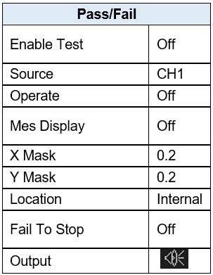
133 14 Default Setup Press the Default button on the front to set the oscilloscope to the recall the factory setup. The details show as below. General Settings Utility 132

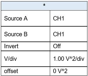
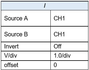
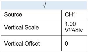
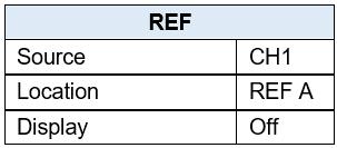
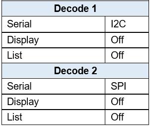
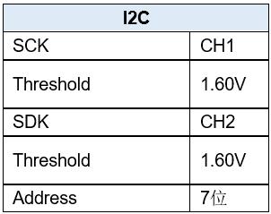
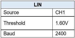
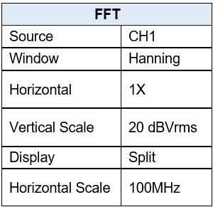
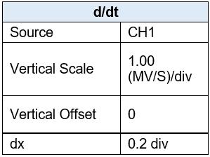
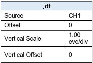
134 Math Settings Decoding Settings (Optional) 133

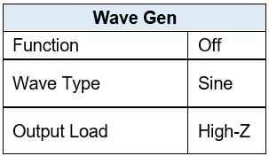
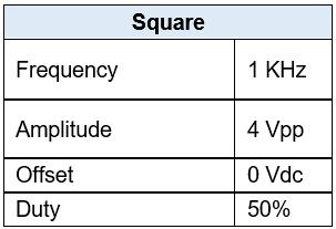
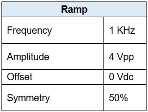
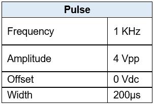
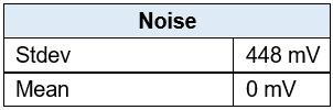
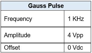
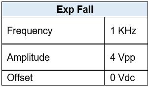
135 Arbitrary Waveform Generator (Optional) 134
136 15 Serial Bus Decoding (DC2560) The oscilloscope provides I2C, SPI, UART/RS232, CAN and LIN serial trigger and decode. This chapter shows how to set and use these types of serial decoding. Serial bus decoding requires the license to be installed. To purchase a license please fill out the license request form and contact B&K Precisions I2C Serial Decode Setup for I2C Signals I2C (Inter-IC bus) signals setup consists of connecting two analog channels to the serial data (SDA) line and the serial clock (SCL) line and specifying the input signal threshold voltage levels. To set up the oscilloscope to capture I2C signals: 1. Press the Decode button to display the Decode menu. 2. Press the Decode softkey and select the desired slot: Decode 1 or Decode Press the Protocol softkey and select I2C with the Universal Knob and push the Universal Knob to confirm. 4. Press the Signal softkey to enter the I2C SIGNAL menu. Figure 107: I2C SIGNAL menu 5. For both the SCL (serial clock) and SDA (serial data) signals: a. Connect an oscilloscope analog or digital channel to the signal on the device under test. b. Press the SCL or SDA softkey and turn the Universal Knob to select the channel for that signal. c. Press the corresponding Threshold softkey and turn the Universal Knob to set the signal threshold voltage level. The threshold voltage level is used in decoding, and it will become the trigger level when the trigger type is set to the selected serial decode slot. Data must be stable during the entire high clock cycle or it will be interpreted as a start or stop condition (data transitioning while the clock is high). I2C Serial Decode To set up I2C serial decode: 1. Press the Decode button to display the Decode menu. Figure 108: I2C decode menu 135

137 2. Press the Address softkey to choose a 7-bit or 10-bit address size. 3. Press the Display softkey and choose On to display the decode line on the display. 4. Press the List softkey to enter the LIST menu. 5. Press the Display softkey and choose On to display the decode list on the display. 6. Press the Scroll softkey and the Lines softkey to set the position of the cursor and the line number of the list with the Universal Knob. The range of Lines is 1 to 7. Interpreting I2C Decode Active waveforms show an active bus (inside a packet/frame). Mid-level blue lines show an idle bus. In the decoded hexadecimal data: Address values appear at the start of a frame. Write addresses appear in dark-green along with the "W" character. Read addresses appear in yellow along with the "R" character. Data values appear in white. Figure I2C decode result "A" indicates Ack (low), "~A" indicates No Ack (high). Decoded text is truncated at the end of the associated frame when there is insufficient space within frame boundaries. Blue vertical bars indicate the horizontal scale should be expanded (and run again) to see decode. 136
138 Red dots in the decode line indicate that more data can be displayed. Scroll or expand the horizontal scale to view the data. Interpreting I2C Lister Data In addition to the standard Time column, the I2C Lister contains these columns: NO: frame number from left to right. TIME: time for each frame. ADDRESS: colored blue for writes, yellow for reads. R/W: yellow R for read, dark green W for write and black X for missing. DATA: data bytes SPI Serial Decode The following order of operations should be followed to ensure that the trigger and decode functions are properly set: Setup for SPI Signals SPI Decode Setup for SPI Signals Serial Peripheral Interface (SPI) signals setup consists of connecting the oscilloscope to a clock, MOSI data, MISO data, and framing signal, then setting the threshold voltage level for each input channel, and finally specifying any other signal parameters. To set up the oscilloscope to capture SPI signals: 1. Press the Decode button to enter the DECODE menu. 2. Press the Decode softkey to select the desired slot (Decode 1 or Decode 2). 3. Press the Protocol softkey and select SPI with the Universal Knob and press the knob to confirm. 4. Press the Signal softkey to enter the SPI SIGNAL menu. Figure SPI SIGNAL menu 5. Press the CLK softkey to enter CLK (clock) menu. Figure SPI CLK menu In the SPI CLK menu: a. Press the CLK softkey. 137
139 b. Turn the Universal Knob to select the channel connected to the SPI serial clock line. c. Press the Threshold softkey and turn the Universal Knob to select the clock signal threshold voltage level. The threshold voltage level is used in decoding and it will become the trigger level when the trigger type is set to the selected serial decode slot. d. Press the Edge Select softkey to select rising edge or falling edge for the selected clock source. This determines which clock edge the oscilloscope will use to latch the serial data. 6. Press the softkey to return to the SIGNAL menu. 7. Press the MISO softkey to enter the SPI MISO menu. In the MISO menu: a. Press the MISO softkey and turn the Universal Knob to select the channel that is connected to a second SPI serial data line. If the channel selected is off, it should be switched on. You can also select Disable. b. Press the Threshold softkey and turn the Universal Knob to select the MISO signal threshold voltage level. The threshold voltage level is used in decoding and it will become the trigger level when the trigger type is set to the selected serial decode slot. 8. Press the softkey to return to the SIGNAL menu. 9. Press the MOSI softkey to enter the SPI MOSI menu. In the MOSI menu: Figure MOSI menu a. Press the MOSI softkey and turn the Universal Knob to select the channel that is connected to a SPI serial data line. If the channel selected is off, it should be switched on. You can also select Disable. b. Press the Threshold softkey and turn the Universal Knob to select the MOSI signal threshold voltage level. The threshold voltage level is used in decoding and it will become the trigger level when the trigger type is set to the selected serial decode slot. 10. Press the softkey to return to the SIGNAL menu. 11. Press the CS softkey to open the SPI CS menu. In the CS menu: Figure SPI CS Menu a. Press the Cs Type softkey to select a framing signal that the oscilloscope will use to determine which clock edge is the first clock edge in the serial stream. You can set the oscilloscope to trigger during a high chip select (CS), a low chip select (~CS), or after a Timeout period during which the clock signal has been idle. 138
140 If the framing signal is set to CS (or ~CS), the first clock edge seen after the CS (or ~CS) signal transitions from low to high (or high to low) is the first clock in the serial stream. Press the CS or ~CS softkey and turn the Universal Knob to select the channel that is connected to the SPI frame line. The label (~CS or CS) for the source channel is automatically set from the Cs Type softkey's setting. The data pattern and the clock transition must occur during the time when the framing signal is valid. The framing signal must be valid for the entire data pattern. If the framing signal is set to CLK Timeout, the oscilloscope generates its own internal framing signal after it sees inactivity on the serial clock line. CLK Timeout: Select Clock Timeout in the Cs Type softkey. Select the Limit softkey and turn the Universal Knob to set the minimum time that the Clock signal must be idle (i.e., no transitions) before the oscilloscope will search for the Data pattern on which to trigger. The Limit value can be set from 100 ns to 1 s. b. Press the Threshold softkey and turn the Universal Knob to select the chip select signal threshold voltage level. The threshold voltage level is used in decoding. It will become the trigger level when the trigger type is set to the selected serial decode slot. 12. Press the Bit Order softkey to set the bit order to LSB or MSB according to the input signal. SPI Serial Decode To set up SPI serial decode: 1. Press the Decode button to display the DECODE menu. Figure SPI DECODE menu 2. Press the Data Length softkey and turn the Universal Knob to set the number of bits in the SPI decoded data. 3. Press the Display softkey and choose On to display the decode line on the display. 4. Press the List softkey to enter the LIST menu. 5. Press the Display softkey and choose Decode 1 or Decode 2 to display the decode list on the display. 6. Press the Scroll softkey and the Lines softkey to set the position of the cursor and the number of lines in the list with the Universal Knob. The range of the Lines setting is 1 to

141 Interpreting SPI Decode Active waveforms show an active bus inside a packet/frame. Mid-level blue lines show an idle bus. The number of clocks in a frame appears in light blue above and to the right of the frame. Decoded hexadecimal data values appear in white. Decoded text is truncated at the end of the associated frame when there is insufficient space within frame boundaries. Pink vertical bars indicate you need to expand the horizontal scale (and run again) to see decode. Red dots in the decode line indicate that there is data that is not being displayed. Scroll or expand the horizontal scale to view the information. Aliased bus values (under-sampled or indeterminate) are drawn in pink. Unknown bus values (undefined or error conditions) are drawn in red. Interpreting SPI Lister Data In addition to the standard Time column, the SPI List contains these columns: NO: frame number from left to right. TIME: time for each frame. MISO: Data for MISO decode. MOSI: Data for MOSI decode. Figure SPI DECODE menu 140
142 15.3 UART/RS232 Serial Decode The following order of operations should be followed to ensure that the trigger and decode functions are set correctly: Setup for UART/RS232 Signals UART/RS232 Decode Setup for UART Signals To set up the oscilloscope to capture UART signals: 1. Press the Decode button to turn on the DECODE menu. 2. Press the Decode softkey and select the desired slot (Decode 1 or Decode 2). 3. Press the Protocol softkey and select UART with the Universal Knob and push it to confirm. 4. Press the Signal softkey to enter the UART/RS232 SIGNAL menu. 5. For both the RX and TX signals: Figure UART SIGNAL menu a. Connect an oscilloscope channel to the appropriate signal on the device under test. b. Press the RX or TX softkeys to select the channel for the signal. c. Press the corresponding Threshold softkey and turn the Universal Knob to select the signal's threshold voltage level. The threshold voltage level is used in decoding and it will become the trigger level when the trigger type is set to the selected serial decode slot. The threshold can be set from -4.5 to 4.5 volts. d. Press Bit Order softkey to select between least significant bit (LSB) and most significant bit (MSB) order. 6. Press the softkey to return to the DECODE menu. 7. Press the Configure softkey to open the BUS CONFIG menu. Set the following parameters. Figure BUS CONFIG menu Baud: Press the Baud softkey, then press the Universal Knob and select a baud rate to match the signal in your device under test. If the desired baud rate is not listed, select Custom on the Baud softkey and press the Custom softkey. Turn the Universal Knob to set the desired baud rate. The maximum baud rate is 50,000,000. Parity Check: Choose Odd, Even, or None, based on your device under test. Stop Bit: Set the number of stop bits in the UART/RS232 words to match your device under test. 141

143 Idle Level: Select if the idle level between transmissions is LOW or HIGH. Data Length: Set the number of bits in the UART/RS232 words to match your device under test (selectable from 5 to 8 bits). UART Serial Decode To set up UART serial decode: 1. Press the Decode button to display the DECODE menu. Figure UART/RS232 DECODE menu 2. Press the Display softkey and choose On to display the decode line on the display. 3. Press the List softkey to enter the LIST menu. 4. Press the Display softkey and choose On to display the decode list on the display. 5. Press the Scroll softkey and the Lines softkey to set the position of the cursor and the line number of the list with the Universal Knob. The range of Lines is from 1 to 7. Figure UART decode example Interpreting UART/RS232 Decode Active waveforms show an active bus (inside a packet/frame). Mid-level blue lines show an idle bus. Mid-level red lines show that the idle level is wrong. The decoded data is displayed in white. 142
144 Decoded text is truncated at the end of the associated frame when there is insufficient space within frame boundaries. Blue vertical bars indicate the need to expand the horizontal scale (and run again) to see decode. When the horizontal scale setting does not permit the display of all available decoded data, red dots will appear in the decoded bus to mark the location of hidden data. Expand the horizontal scale to allow the data to display. An unknown (undefined) bus is shown in red. Interpreting UART/RS232 Lister Data In addition to the standard Time column, the UART/RS232 Lister contains these columns: RX: Receive data. TX: Transmit data. RX err: Parity error or unknown error when receiving data. TX err: Parity error or unknown error when transmit data CAN Serial Decode The following order of operations should be followed to ensure that the trigger and decode functions are set correctly: Setup for CAN Signals CAN Decode Setup for CAN Signals The setup consists of connecting the oscilloscope to a CAN signal and using the SIGNAL menu to specify the signal source, threshold voltage level, baud rate, and sample point. To set up the oscilloscope to capture CAN signals: 1. Press the Decode button to enter the DECODE menu. 2. Press the Decode softkey and select the desired slot (Decode 1 or Decode 2). 3. Press the Protocol softkey and select CAN by turning the Universal Knob. Push the Universal Knob to confirm the selection. 4. Press the Signal softkey to enter the CAN SIGNAL menu. Figure CAN SIGNAL menu 5. Press the CAN-H or CAN-L softkeys and select the channel for the CAN signal. 6. Press the Threshold softkey and turn the Universal Knob to select the CAN signal threshold voltage level. The threshold voltage level is used in decoding and it will become the trigger level when the trigger type is set to the selected serial decode slot. 143
145 7. Press the key to return to the DECODE menu. 8. Press the Configure softkey to enter the BUS CONFIG menu. Figure DECODE CONFIG menu 9. Press the Baud softkey and turn the Universal Knob to select the baud rate that matches your CAN bus signal. The CAN baud rate can be set to predefined baud rates from 5 kb/s up to 1 Mb/s or a custom baud rate from 1 b/s to 1 Mb/s. If the desired baud rate is not listed, select Custom on the Baud softkey. Press the Custom softkey and turn the Universal Knob to set the desired baud rate. 10. Press the Decode Source softkey to set the decoding matching source: CAN_H: The actual CAN_H differential bus. CAN_L: The actual CAN_L differential bus signal. CAN_H-CAN_L: The CAN differential bus signals connected to an analog source channel using a differential probe. Connect the probe's positive lead to the dominant-high CAN signal (CAN_H) and connect the negative lead to the dominant-low CAN signal (CAN_L). CAN Serial Decode To set up CAN serial decode, follow these steps: 1. Press the Decode button to display the DECODE menu. 2. Press the Display softkey and choose On to display the decode line on the display. 3. Press the List softkey to enter the LIST menu. 4. Press the Display softkey and choose Decode 1 or Decode 2 to display the decode list on the display. You can also select Off. 5. Press the Scroll and Lines softkeys to set the position of the cursor and the line number of the list with the Universal Knob. The range of Lines is 1 to 7. The picture below triggers on ID, the ID is 0x
 appears in hex digits in blue when valid or in red to indicate that the oscilloscope's hardware decode calculated a CRC that is different from the incoming data")
146 Interpreting CAN Decode Data bytes appear in hex digits in white. A CRC (cyclic redundancy check) appears in hex digits in blue when valid or in red to indicate that the oscilloscope's hardware decode calculated a CRC that is different from the incoming data stream's stated CRC. Angled waveforms show an active bus (inside a packet/frame). Mid-level blue lines show an idle bus. Decoded text is truncated at the end of the associated frame when there is insufficient space within frame boundaries. Pink vertical bars indicate you need to expand the horizontal scale (and run again) to see decode. Red dots in the decode line indicate that there is data that is not being displayed. Scroll or expand the horizontal scale to view the information. Aliased bus values (under-sampled or indeterminate) are drawn in pink. Interpreting CAN Lister Data In addition to the standard Time column, the CAN Lister contains these columns: NO: frame number from left to right. Type: R indicates remote frame and D indicates data frame. ID: frame ID. Length: Data length code. Data: Data for CAN decode. CRC: Cyclic redundancy check. Ack: Indicates the signal has Ack. Figure 122 -CAN Decode 145
147 15.5 LIN Serial Decode The following order of operations should be followed to ensure that the trigger and decode functions are set correctly: Setup for LIN Signals LIN Decode Setup for LIN Signals LIN (Local Interconnect Network) signal setup consists of connecting the oscilloscope to a serial LIN signal, specifying the signal source, threshold voltage level, baud rate, sample point, and other LIN signal parameters. To set up the oscilloscope to capture LIN signals: 3. Press the Decode button to turn on the DECODE menu. 4. Press the Decode softkey and select the desired slot (Decode 1 or Decode 2). 5. Press the Protocol softkey and select LIN with the Universal Knob and push the Universal Knob to confirm. 6. Press the Signal softkey to enter the LIN SIGNAL menu. Figure LIN SIGNAL menu 7. Press the Source softkey and select the channel for the LIN signal. 8. Press the Threshold softkey and urn the Universal Knob to select the LIN signal threshold voltage level. The threshold voltage level is used in decoding and it will become the trigger level when the trigger type is set to the selected serial decode slot. 9. Press the key to return to the DECODE menu. 10. Press the Configure softkey to enter the BUS CONFIG menu. 11. Press the Baud softkey and turn the Universal Knob to select the baud rate that matches your LIN bus signal. The LIN baud rate can be set to predefined baud rates from 600 to or a custom baud rate from 300 to If the desired baud rate is not listed, select Custom on the Baud softkey. Press the Custom softkey and turn the Universal Knob to set the desired baud rate. LIN Serial Decode To set up LIN serial decode: 1. Press the Decode button to display the DECODE menu. Figure LIN DECODE menu 146

148 2. Press the Display softkey and choose On to display the decode lines on the display. 3. Press the List softkey to enter the LIST menu. 4. Press the Display softkey and choose Off, Decode 1, or Decode Press the Scroll and Lines softkeys to set the position of the cursor. 6. Press the Lines softkey and turn the Universal Knob to determine the number of lines in the list. The range of Lines is 1 to Press the Format softkey and the following choices will be available: Binary Decimal Hex ASCII Figure LIN Fi DECODE example 8. Press the key to return to the DECODE menu. Interpreting LIN Decode Angled waveforms show an active bus (inside a packet/frame). Mid-level blue lines show an idle bus. The hexadecimal ID and parity bits (if enabled) appear in yellow. If a parity error is detected, the hexadecimal ID and parity bits (if enabled) appear in red. Decoded hexadecimal data values appear in white. 147
149 Decoded text is truncated at the end of the associated frame when there is insufficient space within frame boundaries. Pink vertical bars indicate you need to expand the horizontal scale (and run again) to see decode. Red dots in the decode line indicate that there is data that is not being displayed. Scroll or expand the horizontal scale to view the information. Unknown bus values (undefined or error conditions) are drawn in red. Interpreting LIN Lister Data In addition to the standard Time column, the LIN Lister contains these columns: ID: Frame ID. Data: Data bytes. Data Length: Length of data. ID Check: ID parity error. Data Check: Data error. 16 Digital Channels (LA LP2560) This chapter describes how to use the digital channels of a Mixed-Single Oscilloscope (MSO). The digital channels are enabled on the 2560 series that have installed the MSO license. To purchase a license please fill out the license request form and contact B&K Precisions Connecting Digital Probes to Device under Test To connect the digital probes to the device under test: 1. Turn off the power supply to the device under test. This can prevent damage that could occur if two lines are shorted together while making connections. The oscilloscope does not have any voltage at the probes. 2. Connect the digital probe cable LP2560 to the digital channels connector D0-D15 on the front panel of the The digital probe cable is keyed so you can connect it only one way. You do not need to power-off the oscilloscope. The two ports of the digital probe cable are the same, they do not have a specific orientation to connect them to the LP Connect a SMD Mini-grabber test clip to one of the digital ground pins of the probe and then connect the grabber to ground in the device under test. This will improve the signal fidelity and makes sure the oscilloscope gives accurate measurements. 4. Connect a flying lead probe to one of the digital probe digital channel pins; connect a grabber to the flying lead probe, and then connect the grabber to a node in the circuit you wish to test. 148
150 Figure 126 Connecting digital probes 5. Repeat step 4 until you have connected all points of interest Acquiring Digital Waveforms Press the Digital button to open the digital channels and start acquiring digital channel waveforms. For digital channels, each time the oscilloscope takes a sample, it compares the input voltage to the logic threshold. If the voltage is above the threshold, the oscilloscope stores a 1 in the sample memory; otherwise, it stores a Displaying Digital Channels 1. Press the Digital button on the front panel to open the DIGITAL function menu. Figure 127 Digital function menu 2. Press the Channel Height softkey to select Low, Medium or High display type. This control lets you spread out or compress the digital traces vertically on the display for more convenient viewing. The compressed display is useful for displaying digital and analog signals together. Low is only available when a single Channel Group is enabled. 149


151 Figure 128 Channel Height: High Figure 129 Channel Height: Middle Figure 130 Channel Height: Low 150

152 16.4 Turning a Single Digital Channel On or Off 1. Press the Digital button on the front panel to open the DIGITAL menu. 2. Press the ChannelControl softkey and turn the Universal Knob to select the desired channel number. Press the ChannelControl softkey to turn the selected channel on and off (you can also press the Universal Knob to do this) Turning All Digital Channels On or Off 1. Press the Digital button to open the DIGITAL menu. 2. Press the Channel Group softkey to select to select which set of eight digital channels to turn on or off (D0 to D7 or D8 to D15). Using the Universal Knob, set the arrow to the set you wish to turn on or off, then press either the Channel Group softkey or the Universal Knob to toggle the state Changing the Logic Threshold for Digital Channels 1. Press the Digital button to open the DIGITAL menu. 2. Press the Thresholds softkey to enter the THRESHOLDS menu. 3. Press the D0~D7 softkey and turn the Universal Knob to select a logic family preset or select Custom to define you own threshold. 4. Repeat as needed for the D0~D7 softkey. Figure THRESHOLDS menu Logic Family TTL CMOS LVCMOS3.3 LVCMOS2.5 Custom Threshold Voltage 1.5 V 1.65 V 1.65 V 1.25 V Variable from -3 V to +3 V Table 10 - Logic thresholds The threshold you set applies to all channels in the chosen channel group. Values greater than the set threshold are high (1) and values less than the set threshold are low (0). 151
153 If the D0~D7 softkey is set to Custom, press the Custom softkey and turn the Universal Knob to select the desired value (-3 V to 3 V) and push the knob to confirm Displaying Digital Channels as a Bus Digital channels may be grouped and displayed as an 8-bit bus, with each value displayed at the bottom of the display in hex or binary. You can have one or two buses. To configure and display each bus, follow these steps: 1. Press the Digital button to open the DIGITAL menu and display the digital channel waveforms. 2. Press the Digital Bus softkey to enter the DIGITALBUS menu. Figure DIGITALBUS menu 3. Press the Bus Select softkey to select Bus 1 or Bus 2. Selecting Bus 1, for example, will show the B1 bus display in blue at the bottom of the screen just above the softkeys. 4. Press the System Display softkey to choose Hex, Binary, or Decimal to display the number represented by the channel inside the B1 or B2 display. 5. A digital status indicator is displayed immediately above the right-most softkeys. A blue box means the channel is included in the bus. Dark gray means it is excluded from the bus. The channel with the red box is shown in red on the screen. The Sampling rate of the digital channels is displayed at the right of the display under the analog channel information. 152

154 17 Arbitrary Waveform Generator (FG2560) The oscilloscope supports a function and arbitrary waveform generator. The AWG is enabled on the 2560 series that have installed the AWG license (FG2560). The generator provides sine, square, ramp, pulse, DC, noise, cardiac, Gaussian pulse, exponential rise, exponential fall and Arbitrary waveforms. To purchase a license please fill out the license request form and contact B&K Precisions Wave Types and Parameters 1. Press the WaveGen button to enter the built-in Arbitrary waveform generator menu. a) The first press will turn on the backlight of the WaveGen button. It will also turn the generator's output on (WAVEGEN BNC connector on the back panel of the oscilloscope) and enters the WAVEFORM menu. b) A second press of the WaveGen button will turn off the backlight of the WaveGen button and turn the generator's output off. 2. Press the Wave Type softkey and turn the Universal Knob or press the Wave Type softkey continually to select the waveform type. Press the Universal Knob to confirm or wait a few seconds and the choice will automatically be selected. 3. Press the Frequency softkey and turn the Universal Knob to set the waveform frequency. You can press the Frequency softkey again and you'll be able to set either frequency or period. 4. Press the Amplitude softkey and turn the Universal Knob to set the waveform peak-to-peak amplitude. 5. Press the Offset softkey and turn the Universal Knob to set the waveform's DC offset. The Frequency, Amplitude, and Offset softkeys have regular and Fine selections for coarse and fine adjustments. Figure Waveform parameters The softkeys available depend on the Wave Type selected: 153
155 Waveform Sine Square Ramp Pulse DC Noise Cardiac Gaus Pulse Exp Rise Exp Fall Arb Parameters Frequency, Amplitude, Offset Frequency, Amplitude, Offset, Duty (duty cycle) Frequency, Amplitude, Offset, Symmetry Frequency, Amplitude, Offset, Width Offset Stdev (standard deviation), Mean Frequency, Amplitude, Offset Frequency, Amplitude, Offset Frequency, Amplitude, Offset Frequency, Amplitude, Offset Frequency, Amplitude, Offset Table 11 - Waveform parameters The Amplitude and Offset softkeys have two other selections: High-Level and High-Level Fine for the amplitude softkey and Low-Level and Low-Level Fine for the offset softkey. When any of these are chosen, the labels on the softkeys change to High-Level and Low-Level. When the softkeys are pressed and the Universal Knob is turned, the peak (High) value and minimum (Low) value of the waveform are adjusted. The generator's electrical characteristics are: Amplitude (all waveforms): 4 mv to 6 V peak-to-peak DC offset (all waveforms): ±3.0 V Minimum frequency (all waveforms): 1 µhz The maximum frequency depends on the waveform: Waveform Maximum frequency, MHz Sine 25 Square 10 Ramp 0.3 Pulse 10 Cardiac 5 Gaus Pulse 5 Exp Rise 5 154
156 Exp Fall 5 Table 12 - Waveform maximum frequency Sine Waveform Square Waveform Figure 134 Default Sine Waveform Press the Duty softkey and turn the Universal Knob to set the waveform duty cycle. Duty: 20% to 80 % 155
157 Ramp Waveform Figure 135 Default Pulse Waveform Press the Symmetry softkey and turn the Universal Knob to set the ramp symmetry. Symmetry: 0% to 100% Pulse Waveform Figure 136 Default Ramp Waveform Press the Width softkey and turn the Universal Knob to set the pulse width. Press Width softkey again to enter fine adjustment mode with Width Fine softkey being displayed. 156
158 Width: 48 ns to 500 us Figure 137 Default Pulse Waveform DC Waveform Noise Waveform Figure 138 Default DC Waveform Press the Stdev softkey and turn the Universal Knob to set the standard deviation. Press the Mean softkey and turn the Universal Knob to set the mean Stdev: 0.3 to 450 mv 157


159 Mean: to V Figure 139 Default Noise Waveform Cardiac Waveform Figure 140 Default Cardiac Waveform 158
160 Gaus Pulse Figure 141 Default Gaus Pulse 17.2 Arbitrary Waveforms 1. Press the Wave Gen button on the front panel to enable the AWG (arbitrary waveform generator) and enter the WAVEFORM menu. 2. Using a USB cable, connect the oscilloscope to a Windows PC that has the waveform generator software installed (download the software from 3. Double click the waveform generator icon to open the program. 4. Select a waveform file or draw an arbitrary waveform in software. 5. Click the Send wave button at the bottom of the window and it will show a dialog similar to the following: 159

161 Figure Send wave dialog 6. Click the Store location area and select the location to store the waveform in the oscilloscope. 7. Click the Send button. The oscilloscope will display the message Saving waveform data, please wait. 8. When saving is complete, the oscilloscope will display Waveform saved successfully. Then it will enter the WAVEFORM menu, the Wave Type will be set to ArbX (X is an integer between 1 and 4) to the "Store location" chosen in the window above. Figure AWG menu 9. To delete the arbitrary waveform, press the Delete softkey. 10. Press the Setting softkey to enter the SETTING menu. 11. Press the Output Load softkey to select high impedance (High-Z) or 50 Ω Output Impedance 1. Press the Wave Gen button to enter the WAVEFORM menu. 2. Press the Setting softkey to enter the SETTING menu. 3. Press the Output Load softkey to select high impedance (High-Z) or 50 Ω. The impedance selection will be shown on the top line of the display next to Awg. Note: The output impedance of the generator must match that of the oscilloscope or the amplitude of the signal will be incorrect. 160

162 17.4 Set Default Values A softkey in the WAVEFORM menu lets you restore the default wave type, frequency, amplitude, and DC offset: 1. Press the Wave Gen button to enter the WAVEFORM menu. 2. Press the Setting softkey to enter the SETTING menu. 3. Press the Default softkey to restore the default values a sine waveform of 1 khz frequency, 4 Vpp, and 0 V DC offset AWG Self Cal If the ambient operating temperature changes more than 5 C and the instrument runs more than 30 minutes, you should run the AWG self calibration routine to reduce thermal offset effects. 1. Press the Wave Gen button to enter the WAVEFORM menu. 2. Press the Setting softkey to enter the SETTING menu. 3. Press the AWG Self Cal softkey to run the AWG self-calibration program. Figure AWG self-calibration 4. When the self calibration program completes (it will take approximately 5 seconds), press the Run/Stop button to return to the SETTING menu. 161
Quick Start. RSHS1000 Series Handheld Digital Oscilloscope
 Quick Start RSHS1000 Series Handheld Digital Oscilloscope General Safety Summary Carefully read the following safety precautions to avoid personal injury and prevent damage to the instrument or any products
User Manual. SDS2000X Series Digital Oscilloscope UM0102X-E01A 2015 SIGLENT TECHNOLOGIES CO., LTD.
 User Manual SDS2000X Series Digital Oscilloscope UM0102X-E01A 2015 SIGLENT TECHNOLOGIES CO., LTD. Copyright and Declaration Copyright SIGLENT TECHNOLOGIES CO., LTD. All Rights Reserved. Trademark Information
User Manual. SDS1000X-E Series Digital oscilloscope UM0101X-E02B SIGLENT TECHNOLOGIES CO., LTD.
 User Manual SDS1000X-E Series Digital oscilloscope UM0101X-E02B SIGLENT TECHNOLOGIES CO., LTD. Copyright and Declaration Copyright SIGLENT TECHNOLOGIES CO., LTD. All Rights Reserved. Trademark Information
SDS1000X-E Series Super Phosphor Oscilloscope. Quick Start
 SDS1000X-E Series Super Phosphor Oscilloscope Quick Start Copyright Information SIGLENT TECHNOLOGIES CO., LTD. All Rights Reserved. Declaration SIGLENT products are protected by patent law in and outside
Digital Storage Oscilloscopes 2550 Series
 Data Sheet Digital Storage Oscilloscopes 2550 Series The 2550 series digital storage oscilloscopes provide high performance and value in 2-channel and 4-channel configurations. With bandwidth from 70 MHz
User Manual. SDS2000 Series Digital oscilloscope UM01020-E03A 2015 SIGLENT TECHNOLOGIES CO., LTD.
 User Manual SDS2000 Series Digital oscilloscope UM01020-E03A 2015 SIGLENT TECHNOLOGIES CO., LTD. Copyright and Declaration Copyright SIGLENT TECHNOLOGIES CO., LTD. All Rights Reserved. Trademark Information
Tablet Oscilloscope Quick Guide
 Tablet Oscilloscope Quick Guide For tbook Series Shenzhen Micsig Instruments Co., Ltd. Copyright Copyright Shenzhen Micsig Instruments Co., Ltd. All Rights Reserved. Version Version: MKX2014-001; Product
User Manual. Digital Storage Oscilloscopes Models 2534, 2540 & 2542
 User Manual Digital Storage Oscilloscopes Models 2534, 2540 & 2542 General Safety Summary General Safety Summary Review the following safety precautions to avoid injury and prevent damage to this product
User Manual. Digital Storage Oscilloscopes Models 2534, 2540 & General Safety Summary. Version 1.03
 General Safety Summary General Safety Summary User Manual Digital Storage Oscilloscopes Models 2534, 2540 & 2542 Review the following safety precautions to avoid injury and prevent damage to this product
100 MHz Digital Storage Oscilloscope
 Model: 2190E 100 MHz Digital Storage Oscilloscope USER MANUAL 99 Washington Street Melrose, MA 02176 Phone 781-665-1400 Toll Free 1-800-517-8431 Visit us at www.testequipmentdepot.com Safety Summary The
Oscilloscope Guide Tektronix TDS3034B & TDS3052B
 Tektronix TDS3034B & TDS3052B Version 2008-Jan-1 Dept. of Electrical & Computer Engineering Portland State University Copyright 2008 Portland State University 1 Basic Information This guide provides basic
Portable Performance for Debug and Validation
 WaveJet 300A Oscilloscopes 100 MHz 500 MHz Portable Performance for Debug and Validation A UNIQUE TOOLSET FOR PORTABLE OSCILLOSCOPES Key Features 100 MHz, 200 MHz, 350 MHz and 500 MHz bandwidths Sample
4CH/2CH Digital Storage Oscilloscopes
 Model: 2553, 2555, 2556, 2557, 2558, 2559 4CH/2CH Digital Storage Oscilloscopes USER MANUAL Safety Summary The following safety precautions apply to both operating and maintenance personnel and must be
Quick Start. SHS1000 Series Handheld Digital Oscilloscope QS03010-E02B 2015 SIGLENT TECHNOLOGIES CO., LTD
 Quick Start SHS1000 Series Handheld Digital Oscilloscope QS03010-E02B 2015 SIGLENT TECHNOLOGIES CO., LTD Guaranty and Declaration Copyright SIGLENT TECHNOLOGIES CO., LTD. All Rights Reserved. Trademark
WAVEJET 300 SERIES OSCILLOSCOPES. New Cover to Come. Unmatched Performance, Portability, and Value
 WAVEJET 300 SERIES OSCILLOSCOPES New Cover to Come Unmatched Performance, Portability, and Value ALL THE TOOLS YOU NEED Automatic Measurements Save time making measurements on your signals by using the
WAVEJET 300 SERIES OSCILLOSCOPES. Unmatched Performance, Portability, and Value
 WAVEJET 300 SERIES OSCILLOSCOPES Unmatched Performance, Portability, and Value 1 WAVEJET 300 SERIES Unique Capabilities in a Low Bandwidth Oscilloscope The WaveJet 300 Series features unmatched performance
Expect to Make Waves.
 Expect to Make Waves. The New Oscilloscope Large 10.4" LCD touch screen Long capture time Extensive communication capabilities www.lecroy.com The New Oscillos From its large 10.4" LCD touch screen to its
25 MHz Digital Storage Oscilloscope
 99 Washington Street Melrose, MA 02176 Phone 781-665-1400 Toll Free 1-800-517-8431 Visit us at www.testequipmentdepot.com Model: 2530B 25 MHz Digital Storage Oscilloscope USER MANUAL Safety Summary The
RIGOL. Data Sheet. DS1000B Series Digital Oscilloscopes DS1074B, DS1104B, DS1204B. Product Overview. Easy to Use Design. Applications.
 RIGOL Data Sheet Product Overview DS1000B series oscilloscopes are designed with four analog channels and 1 external trigger channel, which can capture multi-channel signal simultaneously and meet industrial
RIGOL. Quick Guide. DS2000 Series Digital Oscilloscope. Jul RIGOL Technologies, Inc
 Quick Guide DS2000 Series Digital Oscilloscope Jul. 2012 RIGOL Technologies, Inc Guaranty and Declaration Copyright 2012 RIGOL Technologies, Inc. All Rights Reserved. Trademark Information RIGOL is a
ScopeMeter 190 Series Specifications
 Seite 1 von 7 ScopeMeter 190 Series Specifications Product Home Features Specifications Models, Options & Accessories Oscilloscope Mode Meter Mode Recorder Mode General Specifications Oscilloscope Mode
imso-104 Manual Revised August 5, 2011
 imso-104 Manual Revised August 5, 2011 Section 1 Getting Started SAFETY 1.10 Quickstart Guide 1.20 SAFETY 1.30 Compatibility 1.31 Hardware 1.32 Software Section 2 How it works 2.10 Menus 2.20 Analog Channel
2510 Series Handheld Digital Storage Oscilloscopes
 Model: 2511, 2512, 2515, 2516 2510 Series Handheld Digital Storage Oscilloscopes USER MANUAL Safety Summary The following safety precautions apply to both operating and maintenance personnel and must be
MSO-28 Oscilloscope, Logic Analyzer, Spectrum Analyzer
 Link Instruments Innovative Test & Measurement solutions since 1986 Store Support Oscilloscopes Logic Analyzers Pattern Generators Accessories MSO-28 Oscilloscope, Logic Analyzer, Spectrum Analyzer $ The
2016 RIGOL TECHNOLOGIES, INC.
 RIGOL Data Sheet Product Overview DS1000B series oscilloscopes are designed with four analog channels and 1 external trigger channel, which can capture multi-channel signal simultaneously and meet industrial
User s Manual. TDO1000/TDO2000 Series Oscilloscopes
 User s Manual TDO1000/TDO2000 Series Oscilloscopes Manual Print History The manual print history shown below lists all the printing dates and editions. The printing date changes when a new edition is released.
Technical Reference. TDS 684A, TDS 744A, & TDS 784A Digitizing Oscilloscope Performance Verification and Specifications
 Technical Reference TDS 684A, TDS 744A, & TDS 784A Digitizing Oscilloscope Performance Verification and Specifications 070-8990-04 Please check for change information at the rear of this manual. Fifth
imso-104 Manual Revised July 19, 2012
 imso-104 Manual Section 1 Getting Started SAFETY 1.10 Quickstart Guide 1.20 SAFETY 1.30 Compatibility 1.31 Hardware 1.32 Software Section 2 How it works 2.10 Menus 2.20 Analog Channel 2.21 On / Off 2.22
USER MANUAL. 27 Full HD Widescreen LED Monitor L27ADS
 USER MANUAL 27 Full HD Widescreen LED Monitor L27ADS TABLE OF CONTENTS 1 Getting Started 2 Control Panel/ Back Panel 3 On Screen Display 4 Technical Specs 5 Care & Maintenance 6 Troubleshooting 7 Safety
USER MANUAL. 28" 4K Ultra HD Monitor L28TN4K
 USER MANUAL 28" 4K Ultra HD Monitor L28TN4K TABLE OF CONTENTS 1 Getting Started 2 Control Panel/ Back Panel 3 On Screen Display 4 Technical Specs 5 Care & Maintenance 6 Troubleshooting 7 Safety Info &
USER MANUAL. 27 Full HD Widescreen LED Monitor L270E
 USER MANUAL 27 Full HD Widescreen LED Monitor L270E TABLE OF CONTENTS 1 Getting Started 2 Control Panel/ Back Panel 3 On Screen Display 4 Technical Specs 5 Care & Maintenance 6 Troubleshooting 7 Safety
Keysight Infiniium S-Series Oscilloscopes
 Keysight Infiniium S-Series Oscilloscopes User s Guide Notices Keysight Technologies 2014-2015 No part of this manual may be reproduced in any form or by any means (including electronic storage and retrieval
Instructions. P MHz 1X/10X Passive Probe
 Instructions P2100 100 MHz 1X/10X Passive Probe 071-0774-01 071077401 Copyright Tektronix, Inc. All rights reserved. Tektronix products are covered by U.S. and foreign patents, issued and pending. Information
Digital Oscilloscope Waveform Generator DC Power Supply Digital Multimeter Spectrum Analyzer Handheld Oscilloscope Probes & Accessories
 Digital Oscilloscope Waveform Generator DC Power Supply Digital Multimeter Spectrum Analyzer Handheld Oscilloscope Probes & Accessories SIGLENT TECHNOLOGIES 产品手册 PRODUCT CATALOG SIGLENT TECHNOLOGIES CO.,
USER MANUAL. 22" Class Slim HD Widescreen Monitor L215DS
 USER MANUAL 22" Class Slim HD Widescreen Monitor L215DS TABLE OF CONTENTS 1 Getting Started Package Includes Installation 2 Control Panel / Back Panel Control Panel Back Panel 3 On Screen Display 4 Technical
MINI PC SCOPE PCSU01. User manual. test leads software download USB cable design enclosure
 MINI PC SCOPE PCSU01 User manual Features test leads software download USB cable design enclosure Specifications oscilloscope: o bandwidth: DC to 200 khz ± 3 db o input impedance: 100 ko / 20 pf o maximum
LeCroy Digital Oscilloscopes
 LeCroy Digital Oscilloscopes Get the Complete Picture Quick Reference Guide QUICKSTART TO SIGNAL VIEWING Quickly display a signal View with Analog Persistence 1. Connect your signal. When you use a probe,
Operation Manual for. SCU1 Signal Conditioning Unit
 Operation Manual for SCU1 Signal Conditioning Unit Table of Contents 1. About this Manual 4 1.1. Symbols Glossary 4 2. Safe Use 4 3. Compatible Magnetometers 5 4. Introduction to the SCU1 5 4.1. Summary
Burlington County College INSTRUCTION GUIDE. for the. Hewlett Packard. FUNCTION GENERATOR Model #33120A. and. Tektronix
 v1.2 Burlington County College INSTRUCTION GUIDE for the Hewlett Packard FUNCTION GENERATOR Model #33120A and Tektronix OSCILLOSCOPE Model #MSO2004B Summer 2014 Pg. 2 Scope-Gen Handout_pgs1-8_v1.2_SU14.doc
USER MANUAL. 27" 2K QHD LED Monitor L27HAS2K
 USER MANUAL 27" 2K QHD LED Monitor L27HAS2K TABLE OF CONTENTS 1 Getting Started 2 Control Panel/ Back Panel 3 On Screen Display 4 Technical Specs 5 Troubleshooting 6 Safety Info & FCC warning 1 GETTING
USER MANUAL Full HD Widescreen LED Monitor L215IPS
 USER MANUAL 21.5 Full HD Widescreen LED Monitor L215IPS TABLE OF CONTENTS 1 Getting Started 2 Control Panel/ Back Panel 3 On Screen Display 4 Technical Specs 5 Care & Maintenance 6 Troubleshooting 7 Safety
Reference. TDS7000 Series Digital Phosphor Oscilloscopes
 Reference TDS7000 Series Digital Phosphor Oscilloscopes 07-070-00 0707000 To Use the Front Panel You can use the dedicated, front-panel knobs and buttons to do the most common operations. Turn INTENSITY
Fluke 190-Series II Firmware Upgrade V11.44
 Fluke 190-Series II Firmware Upgrade V11.44 Requirements 1. Fluke 190- Series II ScopeMeter with firmware prior to V11.44 2. Supported models are: 190-102, 190-104, 190-062, 190-202, 190-204, 190-502,
PicoScope 6407 Digitizer
 YE AR PicoScope 6407 Digitizer HIGH PERFORMANCE USB DIGITIZER Programmable and Powerful 1 GHz bandwidth 1 GS buffer size 5 GS/s real-time sampling Advanced digital triggers Built-in function generator
Noise Detector ND-1 Operating Manual
 Noise Detector ND-1 Operating Manual SPECTRADYNAMICS, INC 1849 Cherry St. Unit 2 Louisville, CO 80027 Phone: (303) 665-1852 Fax: (303) 604-6088 Table of Contents ND-1 Description...... 3 Safety and Preparation
USER MANUAL Full HD Widescreen LED Monitor L215ADS
 USER MANUAL 21.5 Full HD Widescreen LED Monitor L215ADS TABLE OF CONTENTS 1 Getting Started 2 Control Panel/ Back Panel 3 On Screen Display 4 Technical Specs 5 Care & Maintenance 6 Troubleshooting 7 Safety
Overview. Know Your Oscilloscope. Front Panel. Rear Panel. Sharing Agilent s Resources with Engineering Educators
 Know Your Oscilloscope Overview Front Panel Sharing Agilent s Resources with Engineering Educators www.educatorscorner.com Horizontal (time) controls Run control Special purpose menus/controls Trigger
PLL1920M LED LCD Monitor
 PLL1920M LED LCD Monitor USER'S GUIDE www.planar.com Content Operation Instructions...1 Safety Precautions...2 First Setup...3 Front View of the Product...4 Rear View of the Product...5 Installation...6
PL2410W LCD Monitor USER'S GUIDE.
 PL2410W LCD Monitor USER'S GUIDE www.planar.com Content Operation Instructions...1 Safety Precautions...2 First Setup...3 Front View of the Product...4 Rear View of the Product...5 Quick Installation...6
Operator s Manual. WaveJet Touch Oscilloscopes
 Operator s Manual WaveJet Touch Oscilloscopes WaveJet Touch Oscilloscopes Operator s Manual 2014 Teledyne LeCroy, Inc., All rights reserved. Unauthorized duplication of Teledyne LeCroy documentation materials
User Manual. GPS-1000B+ series. Digital Oscilloscope V 1.1
 User Manual GPS-1000B+ series Digital Oscilloscope V 1.1 Brief Introduction Characteristic: The volume of the oscilloscope is cabinet and it is portable 7 Color TFT LCD display 2 channels, Bandwidth:
RIGOL. Quick Guide DSA800E. DSA800E Series Spectrum Analyzer RIGOL TECHNOLOGIES, INC. All Rights Reserved.
 RIGOL Quick Guide 2016 RIGOL TECHNOLOGIES, INC. All Rights Reserved. DSA800E DSA800E Series Spectrum Analyzer General Inspection 1. Inspect the shipping container for damage If your shipping container
PLL2210MW LED Monitor
 PLL2210MW LED Monitor USER'S GUIDE www.planar.com Content Operation Instructions...1 Safety Precautions...2 First Setup...3 Front View of the Product...4 Rear View of the Product...5 Quick Installation...6
SDS1000C Specifications
 SDS1000C Specifications File Version V1.2 Siglent technology Co., Ltd CHARACTERISTIC: The highest Single real-time sampling rate can be up to 500MHzsa/s; Equivalent sampling rate is up to 10GSa/s. Memory
User Manual. Digital Oscilloscope V1.9
 User Manual Digital Oscilloscope V1.9 Declaration All rights reserved. Contents in this Manual are not allowed to copy, extract and translate before being allowed by the company. Brief Introduction Characteristic:
USER MANUAL Full HD Widescreen LED Monitor L236VA
 USER MANUAL 23.6 Full HD Widescreen LED Monitor L236VA TABLE OF CONTENTS 1 Getting Started 2 Control Panel/ Back Panel 3 On Screen Display 4 Technical Specs 5 Care & Maintenance 6 Troubleshooting 7 Safety
Choosing an Oscilloscope
 Choosing an Oscilloscope By Alan Lowne CEO Saelig Company (www.saelig.com) Post comments on this article at www.nutsvolts.com/ magazine/article/october2016_choosing-oscilloscopes. All sorts of questions
DAS240-BAT Portable Multi-Channel Recorder
 DAS240-BAT Portable Multi-Channel Recorder User Manual Safety Summary The following safety precautions apply to both operating and maintenance personnel and must be followed during all phases of operation,
TDS 520B, TDS 540B, TDS 620B, TDS 644B, TDS 680B, TDS 684B, TDS 724A, TDS 744A, & TDS 784A
 Technical Reference TDS 520B, TDS 540B, TDS 620B, TDS 644B, TDS 680B, TDS 684B, TDS 724A, TDS 744A, & TDS 784A Digitizing Oscilloscopes Performance Verification and Specifications 070-9384-01 Copyright
TRANSCENSION 6-CHANNEL DMX DIMMER PACK (order code: BOTE40) USER MANUAL
 USER MANUAL") www.prolight.co.uk TRANSCENSION 6-CHANNEL PACK (order code: BOTE40) USER MANUAL SAFETY WARNING FOR YOUR OWN SAFETY, PLEASE READ THIS USER MANUAL CAREFULLY BEFORE YOUR INITIAL START-UP! CAUTION! Keep this
www.prolight.co.uk TRANSCENSION 6-CHANNEL PACK (order code: BOTE40) USER MANUAL SAFETY WARNING FOR YOUR OWN SAFETY, PLEASE READ THIS USER MANUAL CAREFULLY BEFORE YOUR INITIAL START-UP! CAUTION! Keep this
Winmate Communication INC.
 20.1 Military Grade Display Model: R20L100-RKA2ML User s Manual Winmate Communication INC. May, 2011 1 IMPORTANT SAFETY INSTRUCTIONS Please read these instructions carefully before using the product and
PLL2710W LED LCD Monitor
 PLL2710W LED LCD Monitor USER'S GUIDE www.planar.com Content Operation Instructions...1 Safety Precautions...2 Package Overview...3 First Setup...4 Front View of the Product...5 Rear View of the Product...6
User Manual SDS1000CML+/SDS1000DL+ Digital Oscilloscope UM0101A-E01A SIGLENT TECHNOLOGIES CO,.LTD
 User Manual SDS1000CML+/SDS1000DL+ Digital Oscilloscope UM0101A-E01A SIGLENT TECHNOLOGIES CO,.LTD Declaration Copyright by SIGLENT TECHNOLOGIES CO,.LTD. All rights reserved. Contents in this Manual are
Dragonfly Quad. User Manual V1.4. Order code: EQLED101
 Dragonfly Quad User Manual V1.4 Order code: EQLED101 Safety advice WARNING FOR YOUR OWN SAFETY, PLEASE READ THIS USER MANUAL CAREFULLY BEFORE YOUR INITIAL START-UP! Before your initial start-up, please
KHT 1000C HV-Probe Calibrator. Instruction Manual
 KHT 1000C HV-Probe Calibrator Instruction Manual Copyright 2015 PMK GmbH All rights reserved. Information in this publication supersedes that in all previously published material. Specifications are subject
PicoScope 6 Training Manual
 PicoScope 6 Training Manual DO226 PicoScope 6 Training Manual r2.docx Copyright 2014 Pico Technology CONTENTS 1 Quick guide to PicoScope 6... 1 1.1 The PicoScope way... 1 1.2 Signal view... 2 1.3 Timebase...
DAS240-BAT Portable Multi-Channel Recorder
 DAS240-BAT Portable Multi-Channel Recorder User Manual Test Equipment Depot - 800.517.8431-99 Washington Street Melrose, MA 02176 TestEquipmentDepot.com Safety Summary The following safety precautions
EN - English Washington Street Melrose, MA Phone Toll Free Revision 4 20/06/17
 - English... 1 Instruction Manual Vortex Mixer, Mini Fix Speed, VXMNFS Vortex Mixer, Mini Analog, VXMNAL Vortex Mixer, Mini Digital, VXMNDG Vortex Mixer, Mini Pulsing, VXMNPS 99 Washington Street Melrose,
PXL2760MW LED LCD Monitor
 PXL2760MW LED LCD Monitor USER'S GUIDE www.planar.com Content Operation Instructions...1 Safety Precautions...2 Package Overview...3 First Setup...4 Front View of the Product...5 Rear View of the Product...6
Agilent DSO5014A Oscilloscope Tutorial
 Contents UNIVERSITY OF CALIFORNIA AT BERKELEY College of Engineering Department of Electrical Engineering and Computer Sciences EE105 Lab Experiments Agilent DSO5014A Oscilloscope Tutorial 1 Introduction
GDB-03 Demo Module USER MANUAL GW INSTEK PART NO. 82DB-03000M01 ISO-9001 CERTIFIED MANUFACTURER
 GDB-03 Demo Module USER MANUAL GW INSTEK PART NO. 82DB-03000M01 ISO-9001 CERTIFIED MANUFACTURER This manual contains proprietary information, which is protected by copyright. All rights are reserved. No
University of Utah Electrical & Computer Engineering Department ECE1050/1060 Oscilloscope
 University of Utah Electrical & Computer Engineering Department ECE1050/1060 Oscilloscope Name:, A. Stolp, 2/2/00 rev, 9/15/03 NOTE: This is a fill-in-the-blanks lab. No notebook is required. You are encouraged
PicoScope 6407 Digitizer
 YE AR HIGH PERFORMANCE USB DIGITIZER Programmable and Powerful 1 GHz bandwidth 1 GS buffer size 5 GS/s real-time sampling Advanced digital triggers Built-in function generator USB-connected Signals Analysis
Model P2016. Dual Channel Handheld Digital Storage. Oscilloscope & Multimeter. Quick Scope Guide
 Model P2016 Dual Channel Handheld Digital Storage Oscilloscope & Multimeter Quick Scope Guide General Warranty BNC warrants that the product will be free from defects in materials and workmanship for 3
Agilent Technologies 54522A
 Agilent Technologies 54522A Data Sheet Product Specifications General Specifications Maximum Sample Rate 54522A 2 GSa/s Number of Channels (all are simultaneous acquisition) 54522A: 2 Record Length 32,768
AEROTRAK PORTABLE AIRBORNE PARTICLE COUNTER MODEL 9110 QUICK START GUIDE
 AEROTRAK PORTABLE AIRBORNE PARTICLE COUNTER MODEL 9110 QUICK START GUIDE Thank you for purchasing a TSI AeroTrak Model 9110 Portable Airborne Particle Counter (particle counter). This guide will help you
DISTRIBUTION AMPLIFIER
 MANUAL PART NUMBER: 400-0045-005 DA1907SX 1-IN, 2-OUT VGA/SVGA/XGA/UXGA DISTRIBUTION AMPLIFIER USER S GUIDE TABLE OF CONTENTS Page PRECAUTIONS / SAFETY WARNINGS... 2 GENERAL...2 GUIDELINES FOR RACK-MOUNTING...2
Errata. Title & Document Type: Manual Part Number: Revision Date: HP References in this Manual
 Errata Title & Document Type: Manual Part Number: Revision Date: HP References in this Manual This manual may contain references to HP or Hewlett-Packard. Please note that Hewlett- Packard's former test
Instruction Manual Fixed Speed Vortex Mixer Analog Vortex Mixer Digital Vortex Mixer Pulsing Vortex Mixer
 Instruction Manual Fixed Speed Vortex Mixer Analog Vortex Mixer Digital Vortex Mixer Pulsing Vortex Mixer Table of Contents Package Contents............ 1 Warranty............ 1 Installation............
Advanced Skills with Oscilloscopes
 Advanced Skills with Oscilloscopes A Hands On Laboratory Guide to Oscilloscopes using the Rigol DS1104Z By: Tom Briggs, Department of Computer Science & Engineering Shippensburg University of Pennsylvania
Operator s Manual. WaveAce 1000/2000 Series Oscilloscopes
 Operator s Manual WaveAce 1000/2000 Series Oscilloscopes WaveAce 1000/2000 Oscilloscopes Operator's Manual May, 2012 LeCroy Corporation 700 Chestnut Ridge Road Chestnut Ridge, NY, 10977-6499 Tel: (845)
SNG-2150C User s Guide
 SNG-2150C User s Guide Avcom of Virginia SNG-2150C User s Guide 7730 Whitepine Road Revision 001 Richmond, VA 23237 USA GENERAL SAFETY If one or more components of your earth station are connected to 120
Operating Manual. Automated Gear. Apollo Design Technology, Inc Fourier Drive Fort Wayne, IN USA
 Operating Manual Automated Gear Apollo Design Technology, Inc. 4130 Fourier Drive Fort Wayne, IN 46818 USA PH: +01(260)497-9191 FX: +01(260)497-9192 www.apollodesign.net 11-25-09 5-6 POWERING UP THE RIGHT
SMART Trigger modes like Glitch, Window and Dropout allow you to capture precisely the events of interest.
 9310A Family Digital Oscilloscopes 400 MHz Bandwidth, 100 MS/s Main Features Two and Four Channel Versions 50k, 200k and 1M Point Records DOS Compatible Floppy Disk, PCMCIA portable hard drive and Memory
DataSheet. SDS1000DL Series Digital Oscilloscope
 DataSheet SDS1000DL Series Digital Oscilloscope CHARACTERISTIC: The highest Single real-time sampling rate can be up to 500MHzsa/s; Equivalent sampling rate is up to 50GSa/s. Memory Depth: 32Kpts Trigger
DataSheet SDS1000CFL Series Digital Oscilloscope
 DataSheet SDS1000CFL Series Digital Oscilloscope CHARACTERISTIC: The volume of the oscilloscope is cabinet and it is portable 7 Color TFT LCD display 2/4 channels, Bandwidth: 70MHz-300 MHz Single real-time
PSM-003. Micro Polarization Controller/Scrambler. User Guide
 PSM-003 Micro Polarization Controller/Scrambler User Guide Version: 1.0 Date: August 23, 2012 General Photonics, Incorporated is located in Chino California. For more information visit the company's website
Commander 384. w w w. p r o l i g h t. c o. u k U S E R M A N U A L
 Commander 384 w w w. p r o l i g h t. c o. u k U S E R M A N U A L 1, Before you begin 1.1: Safety warnings...2 3 1.2: What is included...4 1.3: Unpacking instructions...4 2, Introduction 2.1: Features...4
Keysight Infiniium V-Series Oscilloscopes
 Keysight Infiniium V-Series Oscilloscopes User s Guide Notices Keysight Technologies 2015, 2016 No part of this manual may be reproduced in any form or by any means (including electronic storage and retrieval
Contents. Instruction Manual T-Rex Page 2 of 16 Release 1.01
 Contents 1 Safety Precautions... 3 2 Introduction:... 5 3 Theory of Operation... 7 4 Unpacking Procedure... 8 5 Operating TR-Mark III with T-Rex... 9 6 Operating a TR-Mark II with a T-Rex... 13 7 Technical
WVR500 Waveform/Vector Monitor
 Service Manual WVR500 Waveform/Vector Monitor 070-8897-01 Warning The servicing instructions are for use by qualified personnel only. To avoid personal injury, do not perform any servicing unless you are
Agilent 6000 Series Oscilloscope Demo Guide
 Agilent 6000 Series Oscilloscope Demo Guide Agilent 6000 Series Oscilloscope Demo Guide A series of portable oscilloscopes for today s and tomorrow s projects. In the next few minutes you will experience
Introduction...2. Features...2 Safety Precautions...2. Installation...4
 PE1900 Contents Introduction...2 Features...2 Safety Precautions...2 Installation...4 Unpacking the Display...4 Locations and Functions of Controls...4 Connections...5 Using Your Display...7 Turning the
Fluke /
 Fluke 190-104/190-204 ScopeMeter 190 Series II Service Manual PN 4822 872 05405 March 2011 2011 Fluke Corporation, All rights reserved. Printed in the Netherlands All product names are trademarks of their
RIGOL. 快速指南 Quick Guide DSA800 系列频谱分析仪. DSA800 Series Spectrum Analyzer RIGOL Technologies, Inc. All Rights Reserved.
 RIGOL 快速指南 Quick Guide 2011 RIGOL Technologies, Inc. All Rights Reserved. DSA800 系列频谱分析仪 DSA800 Series Spectrum Analyzer General Inspection 1. Inspect the shipping container for damage If your shipping
Litile34 OPERATION MANUAL
 Litile34 OPERATION MANUAL Seamless Tiled Panel Wall Solution for Large Area Digital Signage Display (1st Edition 3/25/2009) All information is subject to change without notice. Approved by Checked by Prepared
Thank you for purchasing a LeCroy Zi Oscilloscope Synchronization ProBus Module (Zi 8CH SYNCH module).
.") Introduction Instructions Thank you for purchasing a LeCroy Zi Oscilloscope Synchronization ProBus Module (Zi 8CH SYNCH module). The module is designed for use on 4 30 GHz WaveMaster 8 Zi oscilloscopes
Introduction Instructions Thank you for purchasing a LeCroy Zi Oscilloscope Synchronization ProBus Module (Zi 8CH SYNCH module). The module is designed for use on 4 30 GHz WaveMaster 8 Zi oscilloscopes
Assembly Level Service Guide
 Assembly Level Service Guide This guide describes how to service the Agilent 53150A, 53151A, and 53152A Microwave Frequency Counters. The information in this guide applies to instruments having the number
16 bit. A digital oscilloscope for the analog world HIGH-RESOLUTION USB OSCILLOSCOPE
 PicoScope 4262 HIGH-RESOLUTION USB OSCILLOSCOPE A digital oscilloscope for the analog world Low noise Two channels 16 MS buffer 16-bit resolution 10 MS/s sampling 5 MHz bandwidth Advanced digital triggers
22" Touchscreen LED Monitor USER'S GUIDE
 22" Touchscreen LED Monitor USER'S GUIDE Content Operation Instructions...1 Unpacking Instructions...2 Safety Precautions...2 Front View of the Product...3 Rear View of the Product...4 Quick Installation...5