Model 974A Quad Counter/Timer Operating Manual
|
|
|
- Jodie Blake
- 5 years ago
- Views:
Transcription
1 ORTEC Model 974A Quad Counter/Timer Operating Manual Printed in U.S.A. ORTEC Part No Manual Revision A
2 Advanced Measurement Technology, Inc. a/k/a/ ORTEC, a subsidiary of AMETEK, Inc. WARRANTY ORTEC* warrants that the items will be delivered free from defects in material or workmanship. ORTEC makes no other warranties, express or implied, and specifically NO WARRANTY OF MERCHANTABILITY OR FITNESS FOR A PARTICULAR PURPOSE. ORTEC s exclusive liability is limited to repairing or replacing at ORTEC s option, items found by ORTEC to be defective in workmanship or materials within one year from the date of delivery. ORTEC s liability on any claim of any kind, including negligence, loss, or damages arising out of, connected with, or from the performance or breach thereof, or from the manufacture, sale, delivery, resale, repair, or use of any item or services covered by this agreement or purchase order, shall in no case exceed the price allocable to the item or service furnished or any part thereof that gives rise to the claim. In the event ORTEC fails to manufacture or deliver items called for in this agreement or purchase order, ORTEC s exclusive liability and buyer s exclusive remedy shall be release of the buyer from the obligation to pay the purchase price. In no event shall ORTEC be liable for special or consequential damages. Quality Control Before being approved for shipment, each ORTEC instrument must pass a stringent set of quality control tests designed to expose any flaws in materials or workmanship. Permanent records of these tests are maintained for use in warranty repair and as a source of statistical information for design improvements. Repair Service If it becomes necessary to return this instrument for repair, it is essential that Customer Services be contacted in advance of its return so that a Return Authorization Number can be assigned to the unit. Also, ORTEC must be informed, either in writing, by telephone [(865) ] or by facsimile transmission [(865) ], of the nature of the fault of the instrument being returned and of the model, serial, and revision ("Rev" on rear panel) numbers. Failure to do so may cause unnecessary delays in getting the unit repaired. The ORTEC standard procedure requires that instruments returned for repair pass the same quality control tests that are used for new-production instruments. Instruments that are returned should be packed so that they will withstand normal transit handling and must be shipped PREPAID via Air Parcel Post or United Parcel Service to the designated ORTEC repair center. The address label and the package should include the Return Authorization Number assigned. Instruments being returned that are damaged in transit due to inadequate packing will be repaired at the sender's expense, and it will be the sender's responsibility to make claim with the shipper. Instruments not in warranty should follow the same procedure and ORTEC will provide a quotation. Damage in Transit Shipments should be examined immediately upon receipt for evidence of external or concealed damage. The carrier making delivery should be notified immediately of any such damage, since the carrier is normally liable for damage in shipment. Packing materials, waybills, and other such documentation should be preserved in order to establish claims. After such notification to the carrier, please notify ORTEC of the circumstances so that assistance can be provided in making damage claims and in providing replacement equipment, if necessary. Copyright 2010, Advanced Measurement Technology, Inc. All rights reserved. *ORTEC is a registered trademark of Advanced Measurement Technology, Inc. All other trademarks used herein are the property of their respective owners.
3 TABLE OF CONTENTS WARRANTY... ii Safety Instructions and Symbols... v Safety Warnings and Cleaning Instructions...vi 1. INTRODUCTION Using this Manual Getting Started COUNTER FUNCTIONS AND CONNECTIONS Counter Display Counter Overflow Indicators Display Test Dwell Control Control Remote/Local Gate Indicator Display Select Time Base Select Preset M 10 N Stop Control Reset Control Count Control Signal Connections to the Model 974A Output Connections Interface Connections Simple Setup Procedure for Standalone Operation General Connection to Power COMMUNICATIONS INTERFACES AND CONFIGURATION SWITCHES Serial Interfaces RS-232-C and 20-mA Current Loop Hardware Switch Settings S S S Input Polarity Selection for Counters mA Current Loop Active or Passive Selection Using a Counting Channel to Show Time iii
4 ORTEC Model 974A Quad Counter/Timer 4. COMMUNICATING WITH A PC VIA RS-232-C RS-232-C Connection to a PC via Modems RS-232-C Direct Connection to a PC The PC s Baud Rate Byte Format Initial Connection to the 974A A BASIC Program for Initial Testing of the Module APPENDIX A. SPECIFICATIONS A.1. Performance A.2. Indicators A.3. Controls A.4. Inputs A.5. Output A.6. Interface A.7. Electrical and Mechanical APPENDIX B. ASCII COMMANDS B.1. Command Words B.2. Data Values B.3. Checksums B.4. Response from the Module B.5. Time Units in Commands B.6. Optional Mask Values B.7. Catalog of Commands for the 974A APPENDIX C. RESPONSE RECORDS FROM THE 974A MODULE C.1. Delimiting Characters C.2. Percent Response Records C.3. Dollar Response Records APPENDIX D. GLOSSARY iv

5 Safety Instructions and Symbols This manual contains up to three levels of safety instructions that must be observed in order to avoid personal injury and/or damage to equipment or other property. These are: DANGER Indicates a hazard that could result in death or serious bodily harm if the safety instruction is not observed. WARNING Indicates a hazard that could result in bodily harm if the safety instruction is not observed. CAUTION Indicates a hazard that could result in property damage if the safety instruction is not observed. In addition, the following symbols may appear on the product: DANGER High Voltage! ATTENTION Refer to Manual Please read all safety instructions carefully and make sure you understand them fully before attempting to use this product. v
6 Safety Warnings and Cleaning Instructions DANGER Opening the cover of this instrument is likely to expose dangerous voltages. Disconnect the instrument from all voltage sources before opening it. WARNING Using this instrument in a manner not specified by the manufacturer may impair the protection provided by the instrument. Cleaning Instructions To clean the instrument exterior:! Remove loose dust on the outside of the instrument with a lint-free cloth.! Remove remaining dirt with a lint-free cloth dampened in a general-purpose detergent and water solution. Do not use abrasive cleaners. CAUTION To prevent moisture inside of the instrument during external cleaning, use only enough liquid to dampen the cloth or applicator. vi
7 vii
8 viii
9 1. INTRODUCTION The ORTEC Model 974A is a four-channel, 100-MHz counter/timer that can be computer controlled or manually operated. The 974A can be used as a three-channel counter with one presettable timer, a four-channel counter (one counter channel presettable), or as a three-channel counter (one counter channel presettable) with one timer. Any one of the four 100-MHz timer/counter channels can be monitored on the large 8-decade LED display. In addition to the four 100-MHz channels, the 974A incorporates an 8-decade, presettable event counter which can only be controlled or read through one of the computer interfaces. Standard computer interfaces built-in to the 974A are RS-232-C and 20-mA current loop. The command format (Appendix B) provides an easy to use language for programming the 974A. All front panel functions (with the exception of DISPLAY TEST) can be remotely controlled via a PC. In addition, several functions not accessible via the front panel are accessible with the computer interfaces. The front panel controls can be locked-out by the ENABLE-REMOTE command from a PC. The input polarity to each of the four counting channels can be independently set using internal connectors. The maximum counting rate for negative input signals is 100 MHz; for positive input signals, 25 MHz. Each of the counting channels can be individually, externally gated through gate 1, 2, 3, and 4 inputs. All four counting channels can be simultaneously, externally gated through the master Gate input. The architecture of the Model 974A Quad Counter/Timer is designed for maximum flexibility. Counter channel 1 acts as the gate controller for counter channels 1, 2, 3, and 4. When counting is started, the input gates to counting channels 1, 2, 3, and 4 are opened. When the accumulated counts in counting channel 1 equal the selected preset value (selected and displayed on the front panel), the counting interval is terminated, and the input gates to counting channels 1, 2, 3, and 4 are closed. If the DWELL control is turned fully counterclockwise to the Off position, no new counting cycle will be initiated. lf however, the DWELL control is set for a chosen dwell time, a new counting cycle will be initiated automatically after the end of the chosen dwell time and automatic reset. Since the input to counting channel 1 can be selected as the internal 0.1 -SEC time base, the internal 1-MIN time base, or an external source (EXT), counting channel 1 can act as a presettable timer or a presettable counter. The event counter, which is accessible only through one of the computer interfaces, is primarily intended as a means of labeling printouts or listings of counting cycles. After the 974A receives an ENABLE_EVENT_AUTO command, the event counter increments one count at the end of each preset counting interval. The contents of the event counter, along with the contents of each of the four 100-MHz counting channels, are output during the implementation of a SHOW_ COUNTS command. This results in an integer labeling of the counting cycle printout. The event counter can be used alternately as a counter of external pulses by the ENABLE_EVENT_ EXTERNAL command. The maximum count rate input to the event counter must be <4 khz; its 1
10 ORTEC Model 974A Quad Counter/Timer capacity is 8 decades. The ENABLE_EVENT_PRESET command allows the event counter to control the total number of counting cycles in a given counting run. After an event preset value is set (via a computer interface), the event counter will allow continuous counter interval recycling until the accumulated value equals the preset value. The complete list of commands is included in Appendix B Using this Manual This manual is organized as follows to help you set up and operate the 974A: Chapter 2 All functions of the front and rear panels. Chapter 3 Hardware characteristics of the three interfaces, instructions for connecting the interfaces to the host PC, and hardware switch settings to control the interface parameters. Chapter 4 Using the module with a PC communicating over the serial interface. Appendixes A, B, C, and D provide the 974A specifications, command syntax, response records and formats, and a glossary of terms Getting Started To avoid the possibility of communications problems due to unfamiliarity with the communications interface, review the following checklist and refer to Fig Determine which communication interface will be used: a. If using the RS-232-C communications interface, the PC must have a serial interface. You will also need an RS-232-C connector cable; a null modem cable/adapter (if a modem is not used); and, depending on the PC, a gender-changer for the RS-232-C cable. b. To use the 20-mA current loop interface, a current loop cable is needed to connect the PC to the 974A. 2. Determine the characteristics of the computer interface: a. If using the RS-232-C interface, determine the PC baud rate, byte configuration, and parity mode. The 974A settings must match the settings of the PC. 2
11 1. INTRODUCTION Fig. 1. Connecting the Model 974A to a PC. b. If using the 20-mA current loop, determine whether the PC is configured for active or passive operation. If the PC is active (provides current for the loop), the 974A must be configured for passive, and vice versa. Jumpers are provided to select the active or passive mode (see Section 3.4). 3. Become familiar with the communication protocol: a. Appendix B gives detailed descriptions of the commands recognized by the 974A. First-time users should read this section to better understand the command format. b. Appendix C gives a detailed description of the responses the Model 974A will send to the PC. This information is critical in determining the results of a particular command sent to the 974A. 3
12 ORTEC Model 974A Quad Counter/Timer 4
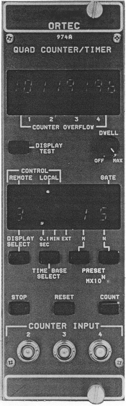
13 2. COUNTER FUNCTIONS AND CONNECTIONS This chapter discusses the Model 974A s controllable front- and rear-panel functions in detail, and the input and output connections are described and defined Counter Display The counter display is an 8-decade display that shows the contents of the counter selected by the DISPLAY SELECT control. It is made up of high-efficiency, 7-segment LED displays. The counter display has leading zero suppression until a COUNTER OVERFLOW occurs. At this time the leading zero suppression is disabled. When the counting channel and the internal 0.1- second time base are selected, a decimal point is inserted between the first and second decade to make it easier to read the actual value being displayed Counter Overflow Indicators The Counter Overflow indicators are four single LEDs which blink at a rate of onetime per second when the corresponding counting channel has exceeded the capacity of its 8-decade counter. The OVERFLOW indicators continue to blink until the counting channel is reset Display Test The DISPLAY TEST push button allows you to test all segments of the front-panel LED displays. When this push button is pressed, all segments of each 7-segment LED display on the front panel are illuminated. If any segment is not functioning properly, it will be apparent immediately Dwell Control The DWELL control is used when the Model 974A is in the stand-alone mode. It allows you to select a variable time for the contents of the selected counting channel to be displayed before being automatically reset and a new counting cycle initiated. This control can be disabled by turning the front-panel control to the extreme counter- clockwise position (Off). The interval of the dwell period can be varied from -0.5 seconds at the counterclockwise position to -12 seconds at the maximum clockwise position Control Remote/Local The REMOTE/LOCAL controls are two LED indicators that show whether the Model 974A is under LOCAL control (front-panel control) or REMOTE control (PC control). The Model 974A powers up in LOCAL mode and can only be placed in REMOTE mode from a PC. In REMOTE 5
14 ORTEC Model 974A Quad Counter/Timer mode, all front-panel functions, with the exception of DISPLAY TEST and DISPLAY SELECT are disabled Gate Indicator The gate LED is an indicator that shows when the 974A is in a counting condition. This LED is illuminated when all conditions are correct to allow counting. The indicator lights when the COUNT push button is pressed and the master gate is not connected or when the dc level at the master gate input exceeds +1.5 V. The indicator will not light when the Stop push button is pressed, when the master gate input level is brought to a dc level of <0.5 V, when the RESET push button is pressed, or when the contents of counting channel 1 reaches a value equal to the selected preset value Display Select The DISPLAY SELECT push button allows you to select the counting channel whose contents are to appear in the counter display. The number of the counting channel selected appears in the 7-segment LED display directly above the push button. When the DISPLAY SELECT push button is pressed, the display sequentially advances from 1 to 4, and then repeats the cycle starting at Time Base Select The TIME BASE SELECT push button allows you to select the source of the input to counting channel 1, the presettable counter. At power up, the internal 0.1-SEC time base is selected. By pressing the push button, the internal 1-MIN time base or the EXT (external) input can be selected. An LED indicator shows which of the options is selected. When EXT input is selected, an input must be provided at the EXT IN (external input) BNC on the rear panel Preset M 10 N The PRESET control consists of one push button labeled M and one labeled N and 2 LED digits to display the selected value for each. The M value represents the multiplier or significant digit of the preset value. The N value is the exponent or power of 10 to which the multiplier is raised. To select a preset value, press the push buttons repeatedly until the proper preset value is displayed. The M value can be selected for any value from 1 to 9. An M value of 0 disables the preset function. The N value can be selected from 0 to 7. For example, to select a preset value of 600, press the M push button until the value of 6 appears in the M display. Next press the N push button until a value of 2 appears in the N display (600 = ). If the 0.1-SEC time base is selected this represents 60.0 seconds; if the 1-MIN time base is selected it represents 600 minutes.
15 2. COUNTER FUNCTIONS AND CONNECTIONS Stop Control The STOP push button allows a counting cycle to be stopped manually at any time the Model 974A is enabled to count. This control is disabled if the REMOTE LED is lit, indicating that a PC has control of the 974A Reset Control The RESET push button allows you to set the contents of all 4 counting channels to a value of zero. This control is disabled in REMOTE mode Count Control The COUNT push button allows the 4 counting channels to be placed manually in a counting condition if the master gate and gates 1, 2, 3, and 4 are at the correct level for counting. This control is disabled when the 974A is in REMOTE mode Signal Connections to the Model 974A COUNTER INPUTS The 974A accepts either positive or negative logic pulses as inputs to the counting channels. The polarity of the input pulses must match the polarity setting of the 974A (Fig. 2). The input circuit to the 974A is dc-coupled to eliminate baseline shifts associated with varying count rates. External capacitive coupling must be provided by you for signals superimposed on a dc level which might exceed +1.5 V. This is because the counter is designed to respond to signal transitions through the fixed threshold of +1.5 V (positive) or -250 mv (negative). There are two important points to consider when supplying signals to the 974A: (1) A single pulse must cross the threshold level only one time. Signals with overshoot or ringing will be counted more than once if such anomalies cause the signals to cross the threshold level. (2) Single pulses with slow rise and fall times should be as clean as possible to prevent multiple counting. As a slow signal approaches the threshold, a small spurious noise pulse can traverse the threshold and return, causing an extra count to be added. EXTERNAL INPUT The timer portion of the 974A is a presettable counter. The source of the pulses counted is controlled by you by pressing the TIME BASE SELECT control on the front panel or remotely from a PC. When the EXT input is selected, a signal must be provided to the presettable counter through the EXT IN input on the rear panel 7
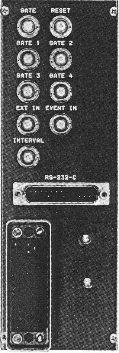
16 ORTEC Model 974A Quad Counter/Timer Fig. 2. Input Connector Orientation for Input Signals. BNC. The input conditions are identical to the counter inputs and can be either positive or negative. The restrictions on the input signal are the same as for the counter inputs. MASTER GATE INPUT A gate input signal or dc level can be connected to the 974A through the rear panel BNC master GATE connector to allow the counting channels to accept and count input signals. The gate will be enabled as long as the input level is $+3 V and will be disabled 8
17 2. COUNTER FUNCTIONS AND CONNECTIONS when the level is <+1.5 V. The driver must be capable of sinking at least 1-mA of current from the gate input circuit. If this signal is left open or unconnected, the gate is enabled to the counting channels. GATES 1, 2, 3, AND 4 An individual gate is provided to allow each counting channel to be selectively gated by providing a level of $+3 V to allow counting or to prevent counting by forcing the input level to <+1.5 V. The signal source must be capable of sinking 1 ma of current from the input connector. If no input is connected counting is enabled. RESET INPUT A reset input signal can be connected to the 974A rear panel BNC RESET connector. To reset the counting channels to zero, a positive input signal of $+3 V with a minimum pulse width must be applied. Z in - 6 kω. Negative signals will not activate the reset circuitry. EVENT INPUT This rear panel BNC is connected to an event counter which can be controlled only from the computer interfaces. Its contents cannot be displayed on the 974A counter display. This counter can be controlled from, and its contents read from, a PC. To be counted, the input signal must exceed a level of +3 V and have a pulse width of >100 ns. The maximum count rate of this counter cannot exceed 4 khz Output Connections INTERVAL OUTPUT A dc level which follows the counting condition of the 974A is available at this BNC connector. When the counting gate is enabled, the dc level is at +5 V nominally. When counting is inhibited (by the master gate, by having reached preset, or by being stopped manually), the dc level is at 0 V nominally. The output through this connector can be used to gate a counting condition in another instrument Interface Connections RS-232-C The 974A is equipped with a male, 25-pin "D" connector with DTE (Data Terminal Equipment) wiring as defined by the EIA RS-232-C standard. This should allow you to easily connect the 974A to a PC with standard cables. lf the PC is also equipped with a male connector, a standard null-modem cable must be used to provide the proper connections to send and receive signals. The 20-mA current loop connections are also present in this connector (Chapter 3). 9
18 ORTEC Model 974A Quad Counter/Timer Simple Setup Procedure for Standalone Operation General The Model 974A Quad Counter/Timer operates on +6-V power furnished from a NIM bin and power supply such as the ORTEC 4001/4002D Series. +6-V power can be added to a NIM bin power supply by using the ORTEC Model 495 Modular 6-V Power Supply. If the 974A is operated in a rack with other equipment, there must be sufficient air flow to prevent localized heating of the integrated circuitry used throughout the instrument. The temperature of equipment in the racks can easily exceed the maximum limits of 120 " F (50 " C) unless precautions are taken Connection to Power Turn off the bin power supply when inserting or removing any modules. Before inserting the Model 974A into the bin, set switches S-1 and S-2 for proper operating conditions according to instructions given in Section 3.3. Power is automatically applied to the 974A when the power is switched on to the bin and power supply in which it is installed. At power-up, an automatic reset is generated in the 974A, resetting all counting channels to 0 and providing a standard set of start up conditions as follows: (1) DISPLAY SELECT is set to counter 1. (2) PRESETs M and N are set to 0. (3) The 0.1-SEC TIME BASE is selected. (4) The counting condition is set to STOP. (5) LOCAL control is enabled. When the 974A is used outside the bin and power supply, be sure that the power extender cable used contains the power conductors to extend all the power supply voltages and the grounds needed to operate the 974A. Be careful to provide adequate grounding when operating the 974A outside a NIM bin. The Model 974A can be used as a counter that operates during a preset interval of time and then stops when the preset time expires. The counter will hold the data acquired until it is reset manually or by an external signal, or it can dwell at the preset stop for an adjustable time period while the data are examined. The counter then resets automatically and a new counting cycle is started. Forth is type of operation, turn the instrument on and connect the sources of the pulses to be counted to the desired counting section inputs. (NOTE: the polarity of the input pulses must agree with the polarity selected by the connector orientation at the counter board input.) The use of the gate inputs is optional, depending on the application requirements. 10
19 2. COUNTER FUNCTIONS AND CONNECTIONS If preset operation is not desired, the preset function can be disabled by repeatedly pressing the M push button until a 0 appears in the display above the switch. The counting interval must then be controlled by manually pressing the COUNT and STOP push buttons on the front panel. Determine the time during which the counters will accept data. To preset the timer count interval, press M to select the multiplier or significant digit of the time value. Next press the N push button to select the power of ten as an exponent. For example, to preset 600, set M to 6 and N to 2 (600 = 6 x 10 2 ). Use the TIME BASE SELECT push button to select either 0.1 SEC or 1 MIN for the unit of time. When 0.1 SEC is selected, a decimal point appears in the display of counter 1 to aid in the interpretation. In the above example the preset value of 600 could be either 60.0 seconds or 600 minutes, depending on whether 0.1 SEC or 1 MIN was selected for the time base. A DWELL control is provided on the front panel of the 974A to reset the counters automatically and start a new counting cycle. The counterclockwise position of the control is an OFF switch that disables the dwell control. As the control is rotated clockwise, the dwell time (time the counter information is displayed before being reset and a new counting cycle initiated), is increased from -0.5 seconds to -12 seconds at the full clockwise position. To view the contents of the four counting channels, press the DISPLAY SELECT push button until the number of the desired counter appears. The contents of the selected counter are displayed in the 8-digit display at the top of the front panel. To start a counting cycle, press the COUNT push button. To stop a counting interval, press the STOP push button. The counting interval can be resumed from the point of interruption by pressing the COUNT push button without pressing the RESET push button. Note that all these functions and more can be implemented by commands through either of the communications interfaces. 11
20 ORTEC Model 974A Quad Counter/Timer 12
21 3. COMMUNICATIONS INTERFACES AND CONFIGURATION SWITCHES 3.1. Serial Interfaces RS-232-C and 20-mA Current Loop The serial communications connector on the rear panel of the 974A is a 25-pin, male D connector with DTE wiring (see glossary). The wiring is as shown: 14 1 protective ground 15 2 transmit data 16 3 receive data POSITIVE TRANSMIT 17 4 request to send 18 5 clear to send 19 6 data set ready data terminal ready 20 7 signal ground POSITIVE RECEIVE NEGATIVE TRANSMIT NEGATIVE RECEIVE The leads shown in uppercase are used for the 20-mA current loop connections to PCs with a 20-mA current loop interface. The leads shown in lower case are used for connection to a standard RS-232-C modem. If modems are not to be used in connecting the 974A to a PC, a null-modem cable will be necessary to enable the 974A to communicate with a PC. The null-modem cable makes up for the fact that both the Model 974A and the PC are wired as DTE devices. The null-modem cable is wired to make the following connections between the 974A and the PC: COMPUTER MODEL 974A PROTECTIVE GROUND 1 ø 1 PROTECTIVE GROUND TRANSMIT DATA 2 ø 3 RECEIVE DATA RECEIVE DATA 3 ø 2 TRANSMIT DATA REQUEST TO SEND 4 ø 5 CLEAR TO SEND CLEAR TO SEND 5 ø 4 REQUEST TO SEND DATA SET READY 6 ø 20 DATA TERMINAL READY DATA TERMINAL READY 20 ø 6 DATA SET READY 13
22 ORTEC Model 974A Quad Counter/Timer If only a short null-modem cable is available, it may be necessary to use a standard RS-232-C male-female connector cable as an extender. If the PC has a female connector rather than a male, a male-female gender changer will also be needed. These parts are available from ORTEC or from other PC parts suppliers. Asynchronous, full duplex character transmission across the serial interface is factory set with the following settings:! 8 data bits per character rather than 7 bits! Parity checking and generation disabled! Parity selection set as even! Baud rate set for 9600! 1 stop bit generated The factory settings can be changed with the hardware switches (Section 3.3). Command records sent to the 974A by the PC must be delimited by a particular ASCII control character. The choice of a delimiting character is fully explained in the introduction to Appendix C. The delimiter is either a carriage return, a line feed, or both. Two separate buffers are maintained in the module for communication with the PC. One is a circular, type-ahead buffer containing room for 64 characters. The second is a 64-byte area which is the buffer for an entire command record before it is executed. An integrated circuit which services the module's serial interface (UART) interrupts the microprocessor when a character arrives and must be deposited into the type-ahead buffer. When time permits, the microprocessor moves the contents of the type-ahead buffer over to the record buffer. If 56 characters accumulate in the type-ahead buffer before the processor has time to transfer them to the record buffer, an X-OFF (Control S) character is sent to the sender to prevent further characters from being transmitted. An X-ON (Control Q) character is then sent out only after the microprocessor has had time to reduce the contents of the type-ahead buffer to 16 characters. 20-mA CURRENT LOOP The 20-mA current operates in exactly the same way as the RS-232-C interface. In fact, the microprocessor does not know which interface is being used. The main difference in the two modes is the electrical characteristics of the signals. RS-232-C uses a change in voltage to transmit data, and the current loop uses a change in current to send and receive data. The current loop is optically coupled to the 974A and can be made to be either active (current for the loop supplied by the 974A) or passive (current for the loop supplied by the connected device) by changing a set of jumpers on the microprocessor board. The transmit 14
23 3. COMMUNICATIONS INTERFACES AND CONFIGURATION SWITCHES and receive loops can be individually selected to be active or passive. The Model 974A is factory-set at shipment with both the transmit and receive set in active mode. The transmit and receive signals are included in the RS-232-C connector. A special cable is needed when using the 20-mA current loop interface to connect the 974A to a PC. This cable is available from ORTEC Hardware Switch Settings The Model 974A has three multi-section programming dip switches that are accessible through cutouts on the left side as viewed from the front of the module. S-2 is mainly associated with the serial interface and is used to format the character which is transmitted over the serial communications link, either RS-232-C or 20-mA current loop. It is also used to select which of the four counting channel's contents will be transmitted and which will be omitted. S-3 is a four-position switch used to select the baud rate at which the characters are transmitted and received over the serial interface. The factory settings of S-1, S-2, and S-3 are as follows: 1. Serial interface selected 2. Eight data bits selected 4. Parity disabled 5. Switch set to even parity 6. One stop bit selected 7. Baud rate set for S-1 OFF (Open) ON (Closed) 1 Not Used Not Used 2 Not Used Not Used 3 Not Used Not Used 4 Not Used Not Used 5 Not Used Not Used 6 Recycle One-Cycle 7 Not Used Not Used 8 Not Used Not Used Only position 6 is used. It selects the action that occurs at the end of a counting cycle. When this switch is set to one-cycle or On, the data collected during the counting cycle are held in the counters after being transferred to the buffer. The data are then transmitted to the PC, and the counting cycle is not repeated. When set to recycle or Off, the counters are reset as soon as the 15
24 ORTEC Model 974A Quad Counter/Timer data is latched in the buffers, and a new counting cycle is started immediately. The dead time between counting cycles is!50 µs S-2 OFF (Open) ON (Closed) 1 Print 1 Skip 1 2 Print 2 Skip 2 3 Print 3 Skip 3 4 Print 4 Skip 4 5 Data Bits (8) Data Bits (7) 6 Parity Enable Parity Disable 7 Parity Even Parity Odd 8 Stop Bits (2) Stop Bits (1) Positions 1 through 4 allow you to select which counting channels will transfer information to the PC. This prevents redundant information from being transmitted when transfer speed is important. In cases where the timer information is always the same, it may not be necessary to transfer this information at the end of every counting cycle. Positions 5 through 8 are used to format the data byte that is transmitted to the PC. They select the data length, parity, and the number of stop bits for each character transmitted over the serial interface. They also select the conditions which are checked on each character received to indicate an error in transmission. The conditions set with these switches must match the conditions selected on the PC connected to the 974A. Position 5 selects the number of data bits: On selects 7 data bits and Off selects 8 data bits. Position 6 disables or enables parity generation or checking. On disables parity and Off enables parity. Position 7 selects the parity which is generated and checked on the characters moved through the serial interface. When set to On odd parity is selected; Off selects even parity. This function is disabled when the switch position is set to parity disable (On). Position 8 selects the number of stop bits attached to the character transmitted via the serial interface. When set to On 1 stop bit is generated, and when set to Off 2 stop bits are generated. 16
25 3. COMMUNICATIONS INTERFACES AND CONFIGURATION SWITCHES S-3 Switch 3 selects the baud rate at which information is transmitted and received over the serial interface. A table of the switch settings and the baud rates follows: BAUD RATE S3-1 S3-2 S3-3 S On On Off On 75 On On Off Off 110 Off Off Off Off On Off On On 150 Off Off Off On 200 On Off On Off 300 Off Off On Off 600 On Off Off On 1200 Off On Off Off 1800 Off On Off On 2400 On Off Off Off 4800 Off On On Off 9600 Off On On On On On On On On On On Off 3.3. Input Polarity Selection for Counters The input polarity to each counting channel is selected as positive or negative by changing the direction in which the cable from the counter input BNCs are connected to the counter boards. Each of the counting channels are physically located on a separate printed wiring board (PWB) which plugs into a larger mother board. Counter number 1 is located nearest the center of the module and counter number 4 is nearest the bottom module bar. The signal input to the counters enter through a coax cable terminated into a four-position connector. To select positive input signals, connect the coax to the connector on the card so that the center conductor of the coax is toward the top of the card and in contact with the pin on the card connector that is nearest the surface of the PWB (Fig. 3). 17
26 ORTEC Model 974A Quad Counter/Timer Fig. 3. Input Connector Orientation for Negative Input Signals. To select negative input signals, connect the coax so that the center conductor of the coax is in contact with the pin of the connector on the card which is at the top of the board but farthest from the surface of the PWB (Fig. 4). Fig. 4. Input Connector Orientation for Positive Input Signals. 18
27 3. COMMUNICATIONS INTERFACES AND CONFIGURATION SWITCHES mA Current Loop Active or Passive Selection To select whether the Model 974A supplies the 20 ma for the current loop (Active) or does not supply the current (Passive), a set of six jumpers is provided on the PWB mounted to the left-top module bar. These jumpers are labeled W-1 through W-6 and are located at the bottom rear of the board near the 12-pin hybrid optical couplers. Three jumpers (W-1 through W-3) are associated with the receive loop, and three are associated with the transmit loop (W-4 through W-6). The transmit and receive loops can be individually selected to be Active or Passive, but all three jumpers associated with the loop must be moved to the proper position. Placing the jumpers toward the center of the board selects Active mode; placing the jumpers toward the rear of the board selects Passive mode (Fig. 5). Fig. 5. Jumpers on the Controller Board Shown in the Active Position Using a Counting Channel to Show Time On each of the three nonpresettable counting channels is a jumper which allows the counter to count the 0.1-second time base, rather than the input signal, when the external time base is selected. This jumper is normally tied to +5 V, but may be changed to allow any of the counters to show time. When either of the internal time bases is selected, the counter functions in the normal manner and responds to the input signals applied to its input. This jumper is located near the 3 hybrid circuits toward the front of the counter boards. When the jumper is placed toward the top of the board, counting time is inhibited; placing the jumper toward the bottom of the 19
28 ORTEC Model 974A Quad Counter/Timer board allows time to be counted when the external mode is selected. (See Fig. 6 for positioning this jumper.) Fig. 6. Jumper on the Counting Board Positioned for Counting Time. 20
29 4. COMMUNICATING WITH A PC VIA RS-232-C This section describes the initial testing of a new 974A. We recommend you familiarize yourself with its command language (Appendixes B and C) before proceeding RS-232-C Connection to a PC via Modems The 974A is equipped with a male, DTE-wired RS-232-C connector (Glossary, DCE and DTE wiring). If the amplifier module is to be remote-controlled from a PC via modems over a transmission line, a standard male-female RS-232-C connector cable should connect the module to the modem (standard modems should have a female, DCE-wired connector) RS-232-C Direct Connection to a PC The 974A module has a male, DTE-wired connector and is ready for direct connection to a modem (female connector with DCE wiring). Most PCs also have male connectors with DTE wiring. All that is needed to connect the module with such PCs is a null modem adapter cable (standard null modem cables have female connectors at both ends). Null modem adapter cables are described along with the RS-232-C interface at the beginning of Chapter The PC s Baud Rate You must know the rate at which the PC communicates. The 974A module is factory set for a default baud rate of If the PC does not operate at 9600 baud and cannot be changed to 9600 baud, you can change the 974A s baud rate with the dip switches discussed in Section 3.3. Once the baud rates have been determined to be equal, setup can continue Byte Format The PC and the 974A must format each byte of data in exactly the same manner for successful use of the serial interface. The dip switches (Section 3.3) can be used to alter the byte characteristics of the module, or you may want to change the PC to match the module's defaults. When shipped, the module is set to transmit and receive 8-bit bytes; this can be changed to 7 bits. The module is set to add a start bit and 1 stop bit to each byte; this can be changed to 2 stop bits (Section 3.3). When shipped, the module does not regard parity; this may be changed so that the module generates and checks for either even or odd parity (Section 3.3). 21
30 ORTEC Model 974A Quad Counter/Timer 4.5. Initial Connection to the 974A After the baud rate and byte format of the 974A and PC have been established to be compatible, it is time to plug the module into a NIM bin. (Be sure the bin power is Off before the module is plugged in.) Note that the bin must be able to provide +6 V power. If it cannot, a separate NIM module is available from ORTEC to supply +6 V power to the bin. Contact your ORTEC representative for more information. Connect the 974A to the PC or modem with RS-232-C cables (Section 5.2). Turn the NIM bin and PC on. If modems are in use, establish a connection between the PC's modem and the module's modem. A program on the PC should now be able to transmit commands to the module and receive and interpret response records sent back by the module A BASIC Program for Initial Testing of the Module 22
31 4. COMMUNICATING WITH A PC VIA RS-232-C 23
32 ORTEC Model 974A Quad Counter/Timer 24
33 COUNT CAPACITY 8 decades, all sections. APPENDIX A. SPECIFICATIONS A.1. Performance COUNTING RATE 100 MHz for negative inputs, all sections; 25 MHz for positive inputs, all sections. TIME BASE 0.1 second or 1 minute increments derived from an internal 1 MHz crystalcontrolled oscillator. Also accepts external input through rear panel BNC labeled EXT IN. Selectable from front panel or through computer control. PULSE PAIR RESOLUTION 10 ns for negative inputs; 40 ns for positive inputs. A.2. Indicators COUNTER DISPLAY 8 characters, 7 LED segments per character plus decimal point. TIMER PRESET 2 characters, 7 LED segments per character. Presettable from front panel or through computer control. Displayed in an M 10 N format. DISPLAYED COUNTER Single-digit display indicates which counter channel is being displayed. CONTROL 2 LEDs indicating either Remote mode operation (front panel controls locked out) or Local mode operation (front panel controls operative). 0.1 SEC Single LED illuminates when the 0.1 second time base is selected. 1 MIN Single LED illuminates when 1 minute time base is selected. EXT Single LED illuminates when Ext time base is selected or when using counter channel 1 as a counter. COUNTER OVERFLOW 1, 2, 3, AND 4 Four separate LEDs illuminate when the corresponding counting channel exceeds the capacity of the counting channel. GATE Single LED illuminates during an active counting interval. 25
34 ORTEC Model 974A Quad Counter/Timer A.3. Controls DISPLAY TEST Push-button switch illuminates all segments of every 7-segment display. RESET Push-button switch resets the internal counting channels to zero and turns Off the overflow indicators. STOP Push-button switch selects the non-counting condition for all counting channels. COUNT Push-button switch enables the counting condition for all counting channels provided the Gate input is not held below +1.5 V dc and the time is not at the preset count condition. DISPLAY SELECT Push-button switch selects the counting channel whose contents will be displayed. DWELL TIME Single-turn control with a switch at the full counterclockwise setting for Off. Off inhibits recycle operation of a preset counting interval. When the control is turned clockwise away from Off, it permits recycling with a dwell time between counting intervals that can be adjusted from 0.3 s to -15 s. This control is disabled when computer control is in effect. M Push-button switch used to set the timer preset value. The "M" preset value [preset = (M 10 N ) time base] is incremented each time the button is pressed. Maximum value = 9. N Push-button switch used to set the timer "N" preset value. The N preset value is incremented each time the button is pressed. Maximum value = 7. TIME BASE SELECT Push button used to select the internal time base of 0.1 SEC or 1 MIN or the EXT IN rear panel input for external time base. SERIAL INTERFACE CONTROL (S-2) An 8-position slide switch accessible through a cutout in the left-side panel. Sections 1 through 4 select the counting channels whose contents will be transmitted when data is transferred to the PC. If the corresponding switch is set for print, the data for that counting channel will be transmitted; if set to the skip position, the data will not be transmitted. Section 5 selects the length of the data byte which will be transmitted over the serial communications interface. On selects 7 data bits; Off selects 8 data bits. Section 6 is used to enable or disable the parity generation and checking when characters are sent or received over the serial interface. If parity is enabled, Section 7 selects either odd or even parity mode. Section 8 selects whether one or two stop bits are added to the character transmitted over the serial interface. 26
35 APPENDIX A. SPECIFICATIONS BAUD RATE SELECT (S-3) A 4-position slide switch accessible through a cutout in the leftside panel. This switch selects the baud rate at which characters are transmitted and received over the serial communications interface (Section 3.3). A.4. Inputs COUNTERS 2, 3, AND 4 Front-panel BNC connectors accept positive unipolar signals; minimum pulse width above threshold, 20 ns at 50% duty cycle. Z in = 1 kω to ground. Threshold is fixed at +1.5 V dc. Input protected to +25 V, dc-coupled. Changing the input connector to the counter board permits independent selection of fast negative logic pulses, 14 ma into 50 Ω. Minimum pulse width above threshold is 4 ns. Input is dc-coupled, 250 mv fixed threshold. COUNTER 1 OR EXT Rear-panel BNC connector accepts positive unipolar signals; minimum pulse width above threshold, 20 ns at 50% duty cycle. Z in = 1 kω to ground. Threshold is fixed at +1.5 V dc. Input protected to +25 V, dc-coupled. Changing the input connector to the negative input permits selection of fast negative logic pulses, 14 ma into 50 Ω. Minimum pulse width above threshold is 4 ns; threshold fixed at!250 mv; input is dc-coupled. MASTER GATE Rear-panel BNC connector accepts standard slow positive logic signal to control counter input gate for all counting sections and the front-panel count LED indicator. A signal >+3 V or open circuit allows counting; a level of <+1.5 V inhibits counting. Protected to +25 V. Driving source must be capable of sinking 0.5 ma positive current during inhibit. GATES 1, 2, 3, AND 4 Rear-panel BNC connectors accept standard slow positive logic signal to control individual counting channel inputs. A signal >+3 V dc or open circuit allows counting; 25 V dc maximum. A level of <+1.5 V inhibits counting. Driving source must be capable of sinking 0.5 ma of positive current during inhibit. EVENT Rear-panel BNC connector accepts standard positive logic pulse to increment the event counter. Signal must exceed a level of +2.5 V dc for a period of >100 ns to increment the event counter. Maximum frequency of input signal is 4 khz. RESET Rear-panel BNC connector accepts standard positive logic pulse to remotely reset all counting sections to zero. A signal of >+3 V dc is needed to reset; a signal of <+1.5 V dc or open circuit is required to not reset. Protected to +25 V dc; minimum pulse width is 100 ns; Z in = 6 kω to ground, dc-coupled. 27
36 ORTEC Model 974A Quad Counter/Timer A.5. Output INTERVAL Rear-panel BNC connector furnishes a positive level during the counting interval. Nominally +5 V dc; Z o = 30 Ω. A.6. Interface SERIAL RS-232-C or 20-mA current loop signal on a single, 25-pin rear-panel-mounted connector. A.7. Electrical and Mechanical POWER REQUIRED +6 V, 1.6 A; +12 V, 70 ma; -12 V, 290 ma. WEIGHT Net 2.4 kg (5.2 lb). Shipping 3.7 kg (8.2 lb). DIMENSIONS NIM-standard double-width module, cm ( in.) front panel per TID (Rev). 28
37 APPENDIX B. ASCII COMMANDS This appendix describes the ASCII command format used by the 974A. B.1. Command Words A command consists of words separated by underscores. The first word of the command is a verb. The second and third words are not always needed and are called nouns and modifiers, respectively. The following is a typical command: SHOW_COUNT_PRESET In the preceding command, SHOW is the verb, COUNT is the noun, and PRESET is the modifier. Only enough letters of a word need be used to make it unique (four letters is always sufficient). The preceding command could thus be abbreviated as SHOW_ COUN_PRES. B.2. Data Values Some commands need to include data values. Such values must be separated from the command keywords by one or more spaces. The data is also sent as ASCII character sequences rather than integer words. If more than one parameter is included in the value, the parameter values must be separated by commas. The following is a command with data values: SET_COUNT_PRESET 1,2 in the preceding command, the module is told to set the preset M value to 1 and the preset N value to 2. These settings result in a preset value of 100 ( ). In the command descriptions of this appendix, the following notation is important: <...> encloses a required value [...] encloses an optional value B.3. Checksums A checksum may optionally be present at the end of any command record. It is used by the module upon reception of the command to verify that the record was transmitted without error. The actual checksum is a byte obtained by adding all of the bytes of the transmitted record together as if they were 8-bit, unsigned, binary integers. Unless otherwise stated, the checksum is to be transmitted as three ASCII characters representing the decimal equivalent of the binary 29
Model 871 Timer and Counter Operating and Service Manual
 Model 871 Timer and Counter Operating and Service Manual Printed in U.S.A. ORTEC Part No. 733650 0503 Manual Revision E $GYDQFHG0HDVXUHPHQW7HFKQRORJ\,QF a/k/a/ ORTEC, a subsidiary of AMETEK, Inc. WARRANTY
Model CO4020 Quad 4-Input Logic Unit Operating and Service Manual
 Model CO4020 Quad 4Input Logic Unit Operating and Service Manual Printed in U.S.A. ORTEC Part No. 762000 1202 Manual Revision C Advanced Measurement Technology, Inc. a/k/a/ ORTEC, a subsidiary of AMETEK,
Model 579 Fast-Filter Amplifier Operating and Service Manual
 Model 579 Fast-Filter Amplifier Operating and Service Manual Printed in U.S.A. ORTEC Part No. 733530 1202 Manual Revision C Advanced Measurement Technology, Inc. a/k/a/ ORTEC, a subsidiary of AMETEK, Inc.
NS-3 RF Noise Source Operation Manual
 RF Noise Source Operation Manual Version 2.04 June 3, 2016 SPECIFICATIONS Frequency... Maximum output level... Output flatness... (at max output level) Impedance... Displayed level... Repeatability...
AES-402 Automatic Digital Audio Switcher/DA/Digital to Analog Converter
 Broadcast Devices, Inc. AES-402 Automatic Digital Audio Switcher/DA/Digital to Analog Converter Technical Reference Manual Broadcast Devices, Inc. Tel. (914) 737-5032 Fax. (914) 736-6916 World Wide Web:
Noise Detector ND-1 Operating Manual
 Noise Detector ND-1 Operating Manual SPECTRADYNAMICS, INC 1849 Cherry St. Unit 2 Louisville, CO 80027 Phone: (303) 665-1852 Fax: (303) 604-6088 Table of Contents ND-1 Description...... 3 Safety and Preparation
AES-404 Digital Audio Switcher/DA/Digital to Analog Converter
 Broadcast Devices, Inc. AES-404 Digital Audio Switcher/DA/Digital to Analog Converter Technical Reference Manual Broadcast Devices, Inc. Tel. (914) 737-5032 Fax. (914) 736-6916 World Wide Web: www.broadcast-devices.com
For warranty service, please contact Microframe at: A technician will gladly assist you.
 Your Microframe System is warranted against failure due to defects in workmanship or material for a period of one (1) year from the date of purchase. Microframe Corporation will repair or replace any defective
VK-P10SE WARRANTY REGISTRATION FORM
 VK-P10SE WARRANTY REGISTRATION FORM Unit Serial Number: Customer Name: Address: Date of Purchase: Purchased From: Dealer Name: Address: IMPORTANT NOTE: In order to receive the full five-year product warranty,
CS x1 RS-232 Computer Controlled Video Switcher. Instruction Manual
 CS-1600 16x1 RS-232 Computer Controlled Video Switcher Instruction Manual Thank you for purchasing one of our products. Please read this manual before using this product. When using this product, always
THE ASTRO LINE SERIES GEMINI 5200 INSTRUCTION MANUAL
 THE ASTRO LINE SERIES GEMINI 5200 INSTRUCTION MANUAL INTRODUCTION The Gemini 5200 is another unit in a multi-purpose series of industrial control products that are field-programmable to solve multiple
Kramer Electronics, Ltd. USER MANUAL. Model: VS x 1 Sequential Video Audio Switcher
 Kramer Electronics, Ltd. USER MANUAL Model: VS-120 20 x 1 Sequential Video Audio Switcher Contents Contents 1 Introduction 1 2 Getting Started 1 2.1 Quick Start 2 3 Overview 3 4 Installing the VS-120 in
USER INSTRUCTIONS MODEL CSI-200 COAXIAL SYSTEM INTERFACE
 USER INSTRUCTIONS MODEL CSI-200 COAXIAL SYSTEM INTERFACE 9350-7676-000 Rev B, 5/2001 PROPRIETARY NOTICE The RTS product information and design disclosed herein were originated by and are the property of
SyncGen. User s Manual
 SyncGen User s Manual 1 IMPORTANT SAFETY INSTRUCTION READ FIRST This symbol, whenever it appears, alerts you to the presence of uninsulated dangerous voltage inside the enclosure-voltage that may be sufficient
MLA-XLR MIDI Line Amplifier
 MIDI Line Amplifier Users Manual , and 0 are trademarks of JLCooper Electronics. All other brand names are the property of their respective owners. User s Manual, First Edition Part Number 932090 2002
AES Channel Digital/Analog Audio Switcher/DA/Digital to Analog Converter
 Broadcast Devices, Inc. AES-408 8 Channel Digital/Analog Audio Switcher/DA/Digital to Analog Converter Technical Reference Manual Broadcast Devices, Inc. Tel. (914) 737-5032 Fax. (914) 736-6916 World Wide
Electronic M.O.P Card. Instruction Manual Model D
 Electronic M.O.P Card Instruction Manual Model D10341-000 Table of Contents 1. General Description................................................................ 1 2. Specifications.....................................................................
INSTALLATION AND OPERATION MANUAL
 INSTALLATION AND OPERATION MANUAL for the Broadcast Tools 6 x 1 Six Input, Single Output Stereo Switcher/Router Broadcast Tools is a registered trademark of Copyright 1994-2002 by All rights reserved.
Installation and Operation Manual. for the. 3 x 2, Ver C. Three Input, Dual Output Stereo Audio Switcher
 for the 3 x 2, Ver C Three Input, Dual Output Stereo Audio Switcher Copyright 1995 2001 by All rights reserved. Except as permitted under the United States Copyright Act of 1976, no part of this document
45LM Series Modules. Features. Specifications. Plug-in Logic and Display Modules for Q45 Series Photoelectric Sensors
 Plug-in Logic and Display Modules for Q45 Series Photoelectric Sensors Three plug-in modules are available: Features Model 45LM58 45LM58D 45LMD Functions Selectable output timing Selectable output timing,
Kramer Electronics, Ltd. USER MANUAL. Model: CV / YC to SDI Converter
 Kramer Electronics, Ltd. USER MANUAL Model: 7508 CV / YC to SDI Converter Contents Contents 1 Introduction 1 2 Getting Started 1 3 Overview 1 4 Your 7508 CV / YC to SDI Converter 2 5 Using Your 7508 CV
Metal Electrode Meter
 Metal Electrode Meter INSTRUCTION MANUAL FOR Metal Electrode Meter MODEL 2900 Serial # Date PO Box 850 Carlsborg, WA 98324 U.S.A. 360-683-8300 800-426-1306 FAX: 360-683-3525 http://www.a-msystems.com Version
RS232 settings are internally definable via jumper blocks, to accommodate interfacing with a wide range of control products.
 Appendix C RS232 Protocol RS232 settings are internally definable via jumper blocks, to accommodate interfacing with a wide range of control products. Baud rate 9600 or 19200 Echo status AUTO or REQUEST
ARS x4 MATRIX SWITCHER Instruction Manual
 ARS-8400 8x4 MATRIX SWITCHER Instruction Manual Thank you for purchasing one of our products. Please read this manual before using this product. When using this product, always follow the instructions
Kramer Electronics, Ltd. USER MANUAL. Model: VA-14. 4x1 Balanced Audio Mixer
 Kramer Electronics, Ltd. USER MANUAL Model: VA-14 4x1 Balanced Audio Mixer Contents Contents 1 Introduction 1 2 Getting Started 2.1 Quick Start 1 1 3 Overview 3 4 Your VA-14 4x1 Balanced Audio Mixer 4
SignalTap Plus System Analyzer
 SignalTap Plus System Analyzer June 2000, ver. 1 Data Sheet Features Simultaneous internal programmable logic device (PLD) and external (board-level) logic analysis 32-channel external logic analyzer 166
4X1 Gefen TV Switcher GTV-HDMI N. User Manual
 4X1 Gefen TV Switcher GTV-HDMI1.3-441N User Manual INTRODUCTION Congratulations on your purchase of the 4x1 GefenTV Switcher. Your complete satisfaction is very important to us. GefenTV GefenTV is a unique
Kramer Electronics, Ltd. USER MANUAL. Model: FC Analog Video to SDI Converter
 Kramer Electronics, Ltd. USER MANUAL Model: FC-7501 Analog Video to SDI Converter Contents Contents 1 Introduction 1 2 Getting Started 1 3 Overview 2 4 Your Analog Video to SDI Converter 3 5 Using Your
Installation and Operation Manual
 PROBLEM SOLVED Installation and Operation Manual INC AES DA 2x6 Six-output, two-input AES/EBU Digital Audio Distribution Amplifier Manual update: 9/17/2015 If you need a firmware upgrade, contact Broadcast
Kramer Electronics, Ltd. USER MANUAL. Model: VP-100. VGA/XGA to RGBHV Converter
 Kramer Electronics, Ltd. USER MANUAL Model: VP-100 VGA/XGA to RGBHV Converter Contents Contents 1 Introduction 1 2 Getting Started 1 2.1 Quick Start 1 3 Overview 3 4 Your VP-100 VGA/XGA to RGBHV Converter
TC Mbps - 622Mbps FIBER OPTIC MODE CONVERTER/REPEATER (Rev A0.1) User's Manual
 User's Manual") TC3004 50Mbps - 622Mbps FIBER OPTIC MODE CONVERTER/REPEATER (Rev A0.1) MODEL: S/N: DATE: Notice! Although every effort has been made to insure that this manual is current and accurate as of date of publication,
TC3004 50Mbps - 622Mbps FIBER OPTIC MODE CONVERTER/REPEATER (Rev A0.1) MODEL: S/N: DATE: Notice! Although every effort has been made to insure that this manual is current and accurate as of date of publication,
RS232 settings are internally definable via jumper blocks, to accommodate interfacing with a wide range of control products.
 Appendix C RS232 Protocol RS232 settings are internally definable via jumper blocks, to accommodate interfacing with a wide range of control products. Baud rate 96ØØ or 192ØØ Echo status AUTO or REQUEST
Commander 384. w w w. p r o l i g h t. c o. u k U S E R M A N U A L
 Commander 384 w w w. p r o l i g h t. c o. u k U S E R M A N U A L 1, Before you begin 1.1: Safety warnings...2 3 1.2: What is included...4 1.3: Unpacking instructions...4 2, Introduction 2.1: Features...4
SDC-500 Digital Optical Chopper Operating Instructions
 SDC-500 Digital Optical Chopper Operating Instructions Gentec-EO USA, Inc. 5825 Jean Road Lake Oswego, OR 97035 Phone: 503-697-1870 Fax: 503-697-0633 ddooley@gentec-eo.com www.gentec-eo.com SDC-500 Manual
PSM-003. Micro Polarization Controller/Scrambler. User Guide
 PSM-003 Micro Polarization Controller/Scrambler User Guide Version: 1.0 Date: August 23, 2012 General Photonics, Incorporated is located in Chino California. For more information visit the company's website
KHT 1000C HV-Probe Calibrator. Instruction Manual
 KHT 1000C HV-Probe Calibrator Instruction Manual Copyright 2015 PMK GmbH All rights reserved. Information in this publication supersedes that in all previously published material. Specifications are subject
OPERATOR MANUAL OSD351 FIBRE OPTIC CCTV TRANSMITTER CARD
 OPERATOR MANUAL OSD351 FIBRE OPTIC CCTV TRANSMITTER CARD OSD351 FIBRE OPTIC CCTV TRANSMITTER CARD Document No:10103701 PAGE 2 C O N T E N T S 1. TECHNICAL SUMMARY...4 1.1 BRIEF DESCRIPTION...4 1.2 TECHNICAL
Kramer Electronics, Ltd. USER MANUAL. Model: 810B. Black Burst / Audio Generator
 Kramer Electronics, Ltd. USER MANUAL Model: 810B Black Burst / Audio Generator Contents Contents 1 Introduction 1 2 Getting Started 1 3 Your 810B Black Burst / Audio Generator 1 4 Connecting the 810B Black
MONITOR POWER Shiloh Road Alpharetta, Georgia (770) FAX (770) Toll Free
 FAX (770) Toll Free") Instruction Manual Model 2099-10xx 10MHz Frequency Source April 2014, Rev. H MENU INTERNAL LEVEL = +10dBm MONITOR POWER 1 2 MODEL 2099 FREQUENCY SOURCE CROSS TECHNOLOGIES INC. ALARM OVEN REMOTE EXECUTE
Instruction Manual Model 2099-10xx 10MHz Frequency Source April 2014, Rev. H MENU INTERNAL LEVEL = +10dBm MONITOR POWER 1 2 MODEL 2099 FREQUENCY SOURCE CROSS TECHNOLOGIES INC. ALARM OVEN REMOTE EXECUTE
Model 1476-C SuperQuad HR
 Model 1476-C SuperQuad HR Installation and Operating Instructions Table of Contents Page Table of Content... 2 System Description... 3 Features... 3 Installation... 4 Internal Setups... 4 Connections...
PCI Express JPEG Frame Grabber Hardware Manual Model 817 Rev.E April 09
 PCI Express JPEG Frame Grabber Hardware Manual Model 817 Rev.E April 09 Table of Contents TABLE OF CONTENTS...2 LIMITED WARRANTY...3 SPECIAL HANDLING INSTRUCTIONS...4 INTRODUCTION...5 OPERATION...6 Video
K3NX Process Meter OPERATION MANUAL
 Cat.No. N90 E1 1 K3NX Process Meter OPERATION MANUAL K3NX Process Meter Operation Manual Produced January 1998 Notice: OMRON products are manufactured for use according to proper procedures by a qualified
MultiMode FOMs -ST and -SMA
 FEBRUARY 1996 MD640A-ST-R2 MD640A-SMA-R2 MD640AE-ST-R2 MD640AE-SMA-R2 MultiMode FOMs -ST and -SMA POWER TD RD RTS CD MultiMode FOM Test Modes Remote Normal Local CUSTOMER SUPPORT INFORMATION Order toll-free
32 Channel CPCI Board User Manual
 0 Sections Page 1.0 Introduction 1 2.0 Unpacking and Inspection 1 3.0 Hardware Configuration 1 4.0 Board Installation 5 5.0 I/O Connections and the Front Panel 5 5.1 Front Panel Layout 5 5.2 Input and
Kramer Electronics, Ltd. USER MANUAL. Models: 6808, SDI-AES De-Embedder 6809, SDI-AES Embedder
 Kramer Electronics, Ltd. USER MANUAL Models: 6808, SDI-AES De-Embedder 6809, SDI-AES Embedder Contents Contents 1 Introduction 1 2 Getting Started 1 3 Overview 1 3.1 About the 6808 SDI-AES De-Embedder
Installation and Operation Manual. for the. SM-6 Programmable Stereo Mixer
 for the Copyright 1996 2001 by Broadcast Tools, Inc. All rights reserved. Except as permitted under the United States Copyright Act of 1976, no part of this document may be reproduced or distributed without
Kramer Electronics, Ltd. USER MANUAL. Model: VS-211HDxl. 3G HD-SDI Automatic Standby Switcher
 Kramer Electronics, Ltd. USER MANUAL Model: VS-211HDxl 3G HD-SDI Automatic Standby Switcher Contents Contents 1 Introduction 1 2 Getting Started 1 2.1 Quick Start 2 3 Overview 3 4 Your VS-211HDxl 3G HD-SDI
LIGHT COPILOT II. elationlighting.com Internet:
 LIGHT COPILOT II E-mail: info@ elationlighting.com Internet: http://www.elationlighting.com 1 Introduction Thank you for your purchase of the LIGHT COPILOT II. The LIGHT COPILOT II is an intelligent lighting
Kramer Electronics, Ltd. USER MANUAL. Models: OC-1N, Video Isolator OC-2, Dual Channel Video Isolator OC-4, Quad Channel Video Isolator
 Kramer Electronics, Ltd. USER MANUAL Models: OC-1N, Video Isolator OC-2, Dual Channel Video Isolator OC-4, Quad Channel Video Isolator Contents Contents 1 Introduction 1 2 Getting Started 1 2.1 Quick Start
INSTRUCTION MANUAL FOR MODEL IOC534 LOW LATENCY FIBER OPTIC TRANSMIT / RECEIVE MODULE
 210 South Third Street North Wales, PA USA 19454 (T) 215-699-2060 (F) 215-699-2061 INSTRUCTION MANUAL FOR LOW LATENCY FIBER OPTIC TRANSMIT / RECEIVE MODULE i TO THE CUSTOMER Thank you for purchasing this
Model R177M and R177S Baseband Switch
 Model R177M and R177S Baseband Switch Installation Guide P/N 1340192 082304 Monroe Electronics 100 Housel Ave Lyndonville NY 14098-0535 800-821-6001 585-765-2254 fax 585-765-9330 www.monroe-electronics.com
Six-Channel TDM Multiplexers for 3G, HD, SDI, and ASI. Installation and Operations. Manual
 Manual DigiLink DLC156 Function modules Six-Channel TDM Multiplexers for 3G, HD, SDI, and ASI Installation and Operations Manual WWW.ARTEL.COM ii DLC156 Function Modules Installation and Operations Manual
500 SERIES DE-ESSER OWNER S MANUAL
 500 SERIES DE-ESSER OWNER S MANUAL Warranty 1. Please register your product online at www.dbxpro.com. Proof-of-purchase is considered to be the responsibility of the consumer. A copy of the original purchase
8024-DSS-02 Issue 2. DSS-8024 Dual Serial Switch USER MANUAL
 8024-DSS-02 Issue 2 DSS-8024 Dual Serial Switch USER MANUAL DSS-8024 Dual Serial Switch User Manual Ross Part Number: 8024-DSS-02 Document Issue: 2 Printing Date: March 15, 2000. Printed in Canada. The
TL MEMORY CONTROL CONSOLE OWNERS MANUAL 02/17/2005. Version 0.6
 TL - 3012 MEMORY CONTROL CONSOLE OWNERS MANUAL Version 0.6 02/17/2005 Page 2 of 6 SPECIFICATIONS Channels: 12 Operating modes: Two Scene Manual Mode Preset Scene Playback Mode Chase Mode Output connector:
PulseFlow FP100 Pulse to 4 20mA Flow Converter (Flow Rate Transmitter / Totalizer / Indicator)
") PulseFlow FP100 Pulse to 4 20mA Flow Converter (Flow Rate Transmitter / Totalizer / Indicator) Submeter Solutions, Inc. PulseFlow FP100 Submeter Solutions, Inc., 800-64METER Page 1 Table of Contents: Installation
PulseFlow FP100 Pulse to 4 20mA Flow Converter (Flow Rate Transmitter / Totalizer / Indicator) Submeter Solutions, Inc. PulseFlow FP100 Submeter Solutions, Inc., 800-64METER Page 1 Table of Contents: Installation
MENU EXECUTE Shiloh Road Alpharetta, Georgia (770) FAX (770) Toll Free
 FAX (770) Toll Free") Instruction Manual Model 2016-1250 Downconverter May 2009 Rev A F=2501.750 G=+25.0 MENU MODEL 2016 DOWNCONVERTER CROSS TECHNOLOGIES INC. ALARM REMOTE POWER EXECUTE Data, drawings, and other material contained
Instruction Manual Model 2016-1250 Downconverter May 2009 Rev A F=2501.750 G=+25.0 MENU MODEL 2016 DOWNCONVERTER CROSS TECHNOLOGIES INC. ALARM REMOTE POWER EXECUTE Data, drawings, and other material contained
3-DRX. AUTOMATIC THREE CHANNEL DIGITAL AES/EBU REPEATER and ANALOG AUDIO SWITCHER INSTALLATION AND OPERATING MANUAL
 3-DRX AUTOMATIC THREE CHANNEL DIGITAL AES/EBU REPEATER and ANALOG AUDIO SWITCHER INSTALLATION AND OPERATING MANUAL 3-DRX SECTION 1 INTRODUCTION The TITUS TECHNOLOGICAL LABORATORIES 3-DRX AUTOMATIC THREE
Modbus for SKF IMx and Analyst
 User manual Modbus for SKF IMx and SKF @ptitude Analyst Part No. 32342700-EN Revision A WARNING! - Read this manual before using this product. Failure to follow the instructions and safety precautions
500 Business Center Drive Pittsburgh, PA USA CAGE 1BGJ7. June 2015 Part Numbers FIBER DRIVER
 Market Central www.secureswitch.com 500 Business Center Drive Pittsburgh, PA 15205 USA 412.494.2800 CAGE 1BGJ7 June 2015 Part Numbers Fiber Driver ST Female (Lead Free) 61-00091 Fiber Driver - ST - Female
DVI Rover 700 User Guide
 DVI Rover 700 User Guide Featuring ExtremeDVI Technology DVI Rover 700 This document applies to Part Numbers: 00-00106 through 00-00141 inclusive. FCC Radio Frequency Interference Statement Warning The
OPERATOR MANUAL OSD390 SERIES 4 CHANNEL VIDEO/AUDIO/DATA FIBER OPTIC TRANSMISSION SYSTEM
 PTY. LTD A.B.N. 83 003 020 504 OPERATOR MANUAL OSD390 SERIES 4 CHANNEL VIDEO/AUDIO/DATA FIBER OPTIC TRANSMISSION SYSTEM OSD390 SERIES 4 CHANNEL VIDEO/AUDIO/DATA FIBER OPTIC TRANSMISSION SYSTEM Document
COMPOSITE VIDEO (BNC) TO VGA VIDEO FORMAT CONVERTER AND SCALER AT-RGB110
 TO VGA VIDEO FORMAT CONVERTER AND SCALER AT-RGB110") User Manual COMPOSITE VIDEO (BNC) TO VGA VIDEO FORMAT CONVERTER AND SCALER AT-RGB110 TABLE OF CONTENTS 1. Introduction... 2 2. Package Contents... 2 3. Features... 2 4. Specification... 2 5. Panel Description...
User Manual COMPOSITE VIDEO (BNC) TO VGA VIDEO FORMAT CONVERTER AND SCALER AT-RGB110 TABLE OF CONTENTS 1. Introduction... 2 2. Package Contents... 2 3. Features... 2 4. Specification... 2 5. Panel Description...
American DJ. User Instructions. American DJ
 Rev. 4/04 American DJ User Instructions American DJ 4295 Charter Street Los Angeles, CA. 90058 www.americandj.com Introduction: Thank you for purchasing the American DJ Tri Beam. The is a unique three
AC182A 8 Input x 8 Output S-Video Matrix Switch with Audio
 Heading AC180A 8 Input x 8 Output Composite Video Matrix Switch with Audio MARCH 2005 AC180A AC182A AC182A 8 Input x 8 Output S-Video Matrix Switch with Audio CUSTOMER SUPPORT INFORMATION Order toll-free
Kramer Electronics, Ltd. USER MANUAL. Model: VM Video Component Distributor
 Kramer Electronics, Ltd. USER MANUAL Model: VM-1045 Video Component Distributor Contents Contents 1 Introduction 1 2 Getting Started 1 2.1 Quick Start 1 3 Overview 3 4 Your VM-1045 Video Component Distributor
Kramer Electronics, Ltd. USER MANUAL. Model: VP-4x4. 4x4 VGA/XGA Audio Matrix Switcher
 Kramer Electronics, Ltd. USER MANUAL Model: VP-4x4 4x4 VGA/XGA Audio Matrix Switcher Contents Contents 1 Introduction 1 2 Getting Started 1 3 Overview 2 4 Your VGA/XGA Audio Matrix Switcher 2 4.1 Connecting
STAGE SETTER-8. User Instructions. Elation Professional 4295 Charter Street Los Angeles Ca
 Introduction STAGE SETTER-8 User Instructions Introduction: Thank you for purchasing the Elation Professional Stage Setter 8. To optimize the performance of this product, please read these operating instructions
Operator s Manual. Ultegra. Health Scale. Fairbanks Scales by Fairbanks Scales Inc. All rights reserved. Revision 5 06/07
 Operator s Manual Ultegra Health Scale Fairbanks Scales 2007 by Fairbanks Scales Inc. All rights reserved 50735 Revision 5 06/07 Amendment Record Ultegra Health Scale 50735 Manufactured by Fairbanks Scales
DA1909 COMPUTER VIDEO LINE DRIVER WITH EQUALIZATION USER S GUIDE
 MANUAL PART NUMBER: 400-0108-002 PRODUCT REVISION: 1 COMPUTER VIDEO LINE DRIVER WITH EQUALIZATION USER S GUIDE INTRODUCTION Altinex appreciates your purchase of the Line Driver. We are sure you will find
Veeder-Root brand Series C628 Dual Preset Counter (C628-8XXX) Technical Manual
 Technical Manual") Introduction Your Veeder-Root brand C628 Dual Preset Counter is one model in a family of 1/8 DIN units which offers breakthrough display technology as well as easy-to-program single-line parameters. Designed
Introduction Your Veeder-Root brand C628 Dual Preset Counter is one model in a family of 1/8 DIN units which offers breakthrough display technology as well as easy-to-program single-line parameters. Designed
560A 500 SERIES COMPRESSOR/LIMITER OWNER S MANUAL
 500 SERIES COMPRESSOR/LIMITER OWNER S MANUAL Warranty 1. Please register your product online at www.dbxpro.com. Proof-of-purchase is considered to be the responsibility of the consumer. A copy of the original
Kramer Electronics, Ltd. USER MANUAL. Models: WPN-11, XGA/Component/CV/YC Transmitter WPN-12, XGA/Component/CV/YC Receiver
 Kramer Electronics, Ltd. USER MANUAL Models: WPN-11, XGA/Component/CV/YC Transmitter WPN-12, XGA/Component/CV/YC Receiver Contents Contents 1 Introduction 1 2 Getting Started 1 3 Overview 1 4 Your Component/RGB/YC/CV/XGA
Installation and Operation Manual. for the. IPC-2, Twin stereo level matching interface
 Preliminary Preliminary Preliminary Preliminary for the Copyright 1996 by All rights reserved. Except as permitted under the United States Copyright Act of 1976, no part of this document may be reproduced
Vorne Industries. 87/719 Analog Input Module User's Manual Industrial Drive Itasca, IL (630) Telefax (630)
 Telefax (630)") Vorne Industries 87/719 Analog Input Module User's Manual 1445 Industrial Drive Itasca, IL 60143-1849 (630) 875-3600 Telefax (630) 875-3609 . 3 Chapter 1 Introduction... 1.1 Accessing Wiring Connections
Vorne Industries 87/719 Analog Input Module User's Manual 1445 Industrial Drive Itasca, IL 60143-1849 (630) 875-3600 Telefax (630) 875-3609 . 3 Chapter 1 Introduction... 1.1 Accessing Wiring Connections
4x4 Component Matrix over CAT-5
 4x4 Component Matrix over CAT-5 EXT-COMPAUD-CAT5-444 User Manual www.gefen.com ASKING FOR ASSISTANCE Technical Support: Telephone (818) 772-9100 (800) 545-6900 Fax (818) 772-9120 Technical Support Hours:
Colour Explosion Proof Video Camera USER MANUAL VID-C
 Colour Explosion Proof Video Camera USER MANUAL VID-C Part Number: MAN-0036-00 Rev 4 Copyright 2002 Net Safety Monitoring Inc. Printed in Canada This manual is provided for informational purposes only.
DUAL/QUAD DISPLAY CONTROLLER Operation Manual
 DUAL/QUAD DISPLAY CONTROLLER Operation Manual Model PXD524 MicroImage Video Systems division of World Video Sales Co., Inc PO Box 331 Boyertown, PA 19512 Phone 610-754-6800 Fax 610-754-9766 sales@mivs.com
Kramer Electronics, Ltd.
 Kramer Electronics, Ltd. Preliminary USER MANUAL Model: 7508 CV/YC to SDI Converter Contents Contents 1 Introduction 1 2 Getting Started 1 2.1 Quick Start 2 3 Overview 3 4 Your 7508 CV/YC to SDI Converter
USB-TG124A Tracking Generator User Manual
 USB-TG124A Tracking Generator User Manual Signal Hound USB-TG124A User Manual 2017, Signal Hound, Inc. 35707 NE 86th Ave La Center, WA 98629 USA Phone 360.263.5006 Fax 360.263.5007 This information is
Kramer Electronics, Ltd. USER MANUAL. Model: WP-220. XGA/Audio/Video Line Driver
 Kramer Electronics, Ltd. USER MANUAL Model: WP-220 XGA/Audio/Video Line Driver Contents Contents 1 Introduction 1 2 Getting Started 1 3 Overview 1 4 Your WP-220 XGA/Audio/Video Line Driver 2 4.1 Your WP-220
MLW-2 Operating Manual
 MLW-2 Operating Manual MLW-2 Operating Manual Introduction The Titus Technological Laboratories MLW-2 was inspired by years of products like the MLW-1, MLW-4, MLW-8, and The Last Word (I and II). The features
DIGITAL SWITCHERS 2100 SERIES
 DIGITAL SWITCHERS 00 SERIES HIGH PERFORMANCE DIGITAL ROUTING OPERATORS MANUAL Includes Module and Frame Information for: AUDIO DAS- DAS-88 DAS-66 VIDEO DVS- DVS-8 DVS-6 DVM-66 DVS-66 SIGMA ELECTRONICS,
Model P/03P Upconverters
 Instruction Manual Model 2005-02P/03P Upconverters October 2013, Rev H 2005 TEST UPCONVERTER GHz 100MHz10MHz 1MHz C KU 70 140 IF IN GAIN DC POWER +DC IN +15V, 200 ma RF OUT DC ALARM LO IF FREQUENCY J1
8 Port HD/SD-SDI Switch
 8 Port HD/SD-SDI Switch User s Guide Models SW-HDSDI-8X1 2008 Avenview Inc. All rights reserved. The contents of this document are provided in connection with Avenview Inc. ( Avenview ) products. Avenview
USER MANUAL. DV-HSW-41 HDMI 4x1 SWITCHER LIT Bergen Boulevard, Woodland Park, NJ Tel FAX Web
 USER MANUAL DV-HSW-41 HDMI 4x1 SWITCHER 244 Bergen Boulevard, Woodland Park, NJ 07424 Tel 973-785-4347 FAX 973-785-3318 Web www.fsrinc.com LIT1372 PROPRIETARY INFORMATION All information in this manual
Installation and Operation Manual
 Installation and Operation Manual INC ADCS-III Analog to Digital Converter and Switcher Manual update 08/22/2007 Firmware Version 1.04 Due to the dynamic nature of product design, the information contained
Kramer Electronics, Ltd. USER MANUAL. Model: Power Amplifier
 Kramer Electronics, Ltd. USER MANUAL Model: 900 Power Amplifier Contents Contents 1 Introduction 1 2 Getting Started 1 3 Overview 1 4 Your 900 Power Amplifier 2 5 Connecting your 900 Power Amplifier 4
CHECK LINE. Model LS-36-LED. Stationary Stroboscope. Operating Manual BY ELECTROMATIC
 CHECK LINE BY ELECTROMATIC Stationary Stroboscope Model LS-36-LED Operating Manual Table of Contents 1.0 Introduction... 02 1.1 Unpacking 1.2 Optional Accessories 2.0 Safety Information... 3 3.0 Controls...
Kramer Electronics, Ltd. USER MANUAL. Models: TR-1YC, s-video Isolation Transformer TR-2YC, s-video Dual Isolation Transformers
 Kramer Electronics, Ltd. USER MANUAL Models: TR-1YC, s-video Isolation Transformer TR-2YC, s-video Dual Isolation Transformers Contents Contents 1 Introduction 1 2 Getting Started 1 2.1 Quick Start 1 3
User Guide. Single-Link DVI Active Cable Extender. DVI-7171c
 User Guide Single-Link DVI Active Cable Extender DVI-7171c TABLE OF CONTENTS SECTION PAGE PRODUCT SAFETY...1 PRODUCT LIABILITY...1 1.0 INTRODUCTION...2 2.0 SPECIFICATIONS...3 3.0 PACKAGE CONTENTS...4 4.0
Kramer Electronics, Ltd. USER MANUAL. Model: VS x1 Video Audio Switcher
 Kramer Electronics, Ltd. USER MANUAL Model: VS-421 4x1 Video Audio Switcher Contents Contents 1 Introduction 1 2 Getting Started 1 3 Overview 1 4 Your Video Audio Matrix Switcher 2 5 Connecting the Video
CrossLine Generator Operation Manual
 WARRANTY MicroImage Video Systems warrants that each CL5400A is free from defects due to faulty materials or improper workmanship for a period of one (1) year. MicroImage Video Systems further warrants
SIERRA VIDEO. SCP-224 Control Panel User s Manual
 SIERRA VIDEO SCP-224 Control Panel 804224 User s Manual SCP-224 CONTROL PANEL User s Manual Sierra Video P.O. Box 2462 Grass Valley, CA 95945 Tel: (530) 478-1000 Fax: (530) 478-1105 Email: info@sierravideo.com
Kramer Electronics, Ltd. USER MANUAL. Model: VM-2DVI. High Resolution / Dual Link 1:2 DVI Distributor
 Kramer Electronics, Ltd. USER MANUAL Model: VM-2DVI High Resolution / Dual Link 1:2 DVI Distributor Contents Contents 1 Introduction 1 2 Getting Started 1 2.1 Quick Start 1 3 Overview 3 4 Your VM-2DVI
45LM Series Modules. 45LM Series Description. Timing Logic Functions. LED Signal Strength Display Function. 45LM Series Modules Specifications
 Plug-in Logic and Display Modules for Q45 Series Sensors 45LM Series Description Q45 Series sensors easily accept the addition of timing and signal strength display functions. Seven plug-in modules are
DXI SAC Software: Configuring a CCTV Switcher. Table of Contents
 APPLICATION NOTE MicroComm DXI DXI SAC Software: Configuring a CCTV Switcher Table of Contents 1. Intent & Scope... 2 2. Introduction... 2 3. Options and Parameters... 2 3.1 When to switch the CCTV...2
192 Channel DMX Controller
 DM-X 92 Channel DMX Controller USER MANUAL 54. 9UK Vers ion. D M X 5 2 C O N T R O L L E R S E R I E S Content. Before you begin. What is included.......2 Unpacking instructions....3 Safety instructions...
ES-450J2 Universal 2 Channel Jog/Shuttle Remote
 ES-450J2 Universal 2 Channel Jog/Shuttle Remote Users Manual ES-450, ES-450J and ES-450J2 are trademarks of JLCooper Electronics. All other brand names are the property of their respective owners. ES-450J2
Passive Four Channel Stereo/Mono Mixer/Splitter. Artcessories. User's Manual
 Passive Four Channel Stereo/Mono Mixer/Splitter Artcessories User's Manual IMPORTANT SAFETY INSTRUCTION READ FIRST This symbol, whenever it appears, alerts you to the presence of uninsulated dangerous