Network Performance Tester PDH/DSn/SDH/SONET/OTN/Jitter Measurement with One Unit
|
|
|
- Hilda Booker
- 5 years ago
- Views:
Transcription

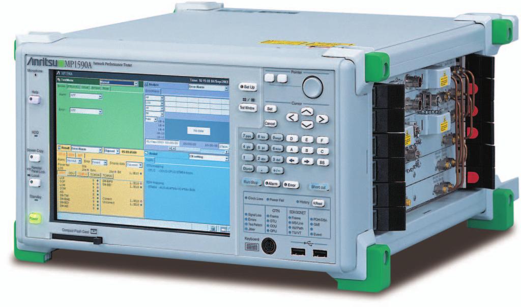
1 MP1590A Network Performance Tester PDH/DSn/SDH/SONET/OTN/Jitter Measurement with One Unit

2 Supports ITU-T G.709 OTN Measurement The MP1590A Network Performance Tester is a measuring instrument capable of testing PDH, DSn, SDH/SONET and OTN equipment as well as making jitter measurements with only one unit. It also can perform OTN, SDH/SONET testing using the input wavelength from an external Tunable Laser Source. Jitter measurement and external optical input functions are provided by plug-in units that can be used in various combinations as needed. The MP1590A is equipped with Random error insertion and variable optical output power functions. So it can efficiently evaluate Forward Error Correction (FEC) used with OTN equipment. For SDH/SONET equipment, the MP1590A can perform Tandem Connection and Automatic Protection Switch (APS) tests. For PDH or DSn equipment, it can perform function tests using multiplexer/demultiplexer (MUX/DEMUX) measurement, error insertion or alarm addition. PDH (Plesiochronous Digital Hierarchy) SDH/SONET (Synchronous Digital Hierarchy/ Synchronous Optical Network) DSn (Digital Signal Level n) OTN (Optical Transport Network) 2
3 Supports 1.5 Mbit/s to 10.7 Gbit/s interfaces with only one unit The MP1590A supports the following electrical and optical interfaces. Electrical interfaces: PDH (2.048, 8.448, , Mbit/s), DSn (1.544, Mbit/s), STM-0/1/64, STS1/3/192 (51.84, , Mbit/s), OTU-2 (10.71 Gbit/s) Optical interfaces: STM-0/1/4/16/64, OC-1/3/12/48/192 (51.84, , , , Mbit/s), OTU-1 (2.66 Gbit/s), OTU-2 (10.71 Gbit/s) Because a plug-in system is employed, units can be used in various combinations as needed. ITU-T G.709 OTN measurement Supports setting/monitoring of all overhead for OTU-1 (2.66 Gbit/s) and OTU-2 (10.71 Gbit/s) conforming to ITU-T G.709. OTN equipment can be tested by error/alarm generation/ detection functions. In particular, the Random error insertion function on the MP1590A enables FEC function evaluation. The built-in optical output power adjustable function allows one MP1590A to test the error correction ratio of OTN equipment based on its input power specification. Concatenation mapping In addition to traditional concatenation mapping, the MP1590A supports arbitrary concatenation. Arbitrary concatenation SONET STS3-nc (n = 2 to 16) SDH VC-4-nc (n = 2 to 16) SDH/SONET functions The MP1590A is applicable for both SDH and SONET frames. It is easy to switch between SDH and SONET. Transmission/reception with Tandem Connection pattern and "No frame" pattern are possible. Also, APS switching time testing is supported. Moreover, various error/alarm generation functions enable stress testing of SDH/SONET equipment. Error analysis (error performance) Measurements conforming to ITU-T Rec. G.821/G.826/G.828/ G.829, M.2100/M.2101/M.2110/M.2120 and Telcordia GR-820 can be performed. Jitter generation/measurement Installing a 10/10.7G jitter unit enables SDH/SONET (52 to 9953 MHz), OTU-1 (2.66 GHz), OTU-2 (10.71 GHz) and 10.3 GHz jitter generation/measurement. Jitter tolerance and jitter transfer characteristic measurements conforming to ITU-T Rec. G.783, G.825, G.8251 and Telcordia GR-253 can be performed. The measured results are displayed in numeric values and graphs, allowing user evaluation and simplifying pass/fail judgment. Through mode Through mode operation can be used for all bit rates of PDH/DSn, SDH/SONET and OTU-1/OTU-2. For SDH/SONET and OTU-1/OTU-2, either transparent through or overhead overwrite modes can be selected. Clock/frame synchronization signal output Divided-by-16 clock or frame synchronization signals can be output. Connecting this signal output to an external sampling oscilloscope allows the MP1590A to evaluate errors/alarms and the oscilloscope to evaluate the input waveform simultaneously. The MP1590A can provide both a transmission signal and the synchronized recovered clock from its received signal, making waveform analysis possible for devices that do not have their own synchronized signal output. External optical input function By using the MU150134A 10/10.7G Optical Unit (Transmission External Modulation), OTN and SDH/SONET tests based on a user-provided input wavelength can be performed. This is best suited to provide the reference optical source for jitter measurement because of its very fine waveform quality and low jitter characteristics. SDH/SONET overhead setting and monitoring SOH/TOH and POH within an SDH/SONET frame can be set and transmitted. Real-time monitoring is supported for K1/K2 bytes within SOH/TOH, K3/K4 bytes within POH, AU/STS pointer, TU/VT pointer, path trace and N1/Z5, N2 of the received signal. 3

 mapping ODU1 No frame OPU1 OTU-1 (2.")


4 OTN Test Solution Transmission/reception with OTU-1 (2.66 Gbit/s) and OTU-2 (10.71 Gbit/s) frames conforming to ITU-T G.709 or with No frame can be performed. When mapping client is set to STM-64/STS192 or STM-16/STS48, various mappings used for SDH/SONET can be selected. OTU-2 OTU-1 Overhead setting All overhead (except for parity, MFAS, and JC) can be set arbitrarily. Moreover, multi-frame overhead such as TTI can also be set up easily. Error/alarm test ODU2 OPU2 STM-64/STS192 Async/Sync No frame NULL PRBS OTU-2 (10.71 Gbit/s) mapping ODU1 No frame OPU1 OTU-1 (2.66 Gbit/s) mapping STM-16/STS48 Async/Sync NULL PRBS A stress test on OTN equipment can be performed by arbitrarily generating FAS, BIP-8 or BEI errors as well as LOF, LOM and AIS alarms and monitoring them with the MP1590A. FEC decode test The MP1590A random error insertion function can evaluate whether the FEC function of the DUT meets the requirements of ITU-T G.709. By using the optional optical output power adjustable function, the error correction ratio vs optical input power to DUT can be tested by a single MP1590A unit. Other equipment Random error insertion function To FEC evaluation, it is an indispensable function and evaluation is impossible in the error insertion former method. Through mode Former method FEC converter New method Variable optical attenuator MP1590A DUT DUT External equipment is not needed to vary the optical output power, and performance testing of the DUT FEC decoder is possible using only MP1590A. Two types of through mode testing are provided for OTN mapping: transparent through mode and overhead overwrite mode. Various errors can be inserted and alarms can be added to through signals. Transparent Loops the received signal back and outputs it as is. Random error insertion is possible. MP1590A Rx Overhead setting Tx Overhead overwrite Replaces the overhead part of the received signal with the overhead set on the MP1590A, or with programmed data. MP1590A Rx Tx Overhead monitor 4
5 SDH/SONET, PDH, DSn Test Solution Mapping structures from 1.5 Mbit/s to 10 Gbit/s can be selected. Mappings for SDH, SONET, Japan, PDH (Europe) and DSn (North America) are supported. STM-64 STM-16 STM-4 STM-1 STM-0 AUG AU-4 VC-4 x 3 AU-3 VC-3 x 3 TUG-3 TU-3 VC-3 x 7 FDDI (Async.) 139M (Async.) 34M (Sync.) 34M (Async.) 45M (Async.) x 7 TUG-2 TU-2 VC-2 6M (Async.) x 3 6M (Bit sync.) mc TU-12 VC-12 2M (Async.) 2M (Bit sync. F) 2M (Byte sync. F) x 4 TU-11 VC M (Async.) 1.5M (Bit sync. F) 1.5M (Byte sync. F) 384k D/V Mapping structure (SDH) Byte D/V STS192 STS48 STS12 STS3 STS1 STS3 x 3 STS3cSPE STS1cSPE x 3 TUG-3 TU-3 VC-3 x 7 FDDI (Async.) 139M (Async.) 34M (Sync.) 34M (Async.) 45M (Async.) x 7 VTG VT6 VT6SPE 6M (Async.) x 3 6M (Bit sync.) mc VT2 VT2SPE 2M (Async.) 2M (Bit sync. F) 2M (Byte sync. F) x 4 VT1.5 VT1.5SPE 1.5M (Async.) 1.5M (Bit sync. F) 1.5M (Byte sync. F) 384k D/V Mapping structure (SONET) Byte D/V 5


6 Concatenation mapping In concatenation mapping, STM-1c to STM-64c/STS3c to STS192c can be selected. In addition to traditional concatenation mappings such as VC4-64c/STS192cSPE and VC4-16c/ STS48cSPE, the MP1590A supports VC4-nc/STS3ncSPE arbitrary concatenation. STM-64c STM-16c STM-4c STM-1c x 4 x 4 x 4 VC4-64c VC4-16c VC4-4c VC4c VC4-nc APS Function Automatic Protection Switch (APS) testing can be performed. The switching time test measures the time from error/alarm occurrence to release. Switching time is measured with 0.1 msec resolution. Switch time Detects Error/Alarm, command Error/Alarm generation Switching time Error/Alarm release Concatenation mapping (SDH) STS192c STS48c STS12c STS3c x 4 x 4 x 4 STS192cSPE STS48cSPE STS12cSPE STS3cSPE STS3 ncspe Concatenation mapping (SONET) Add/Drop function When PDH/DSn asynchronous mapping is selected for a SDH/ SONET bit rate, the PDH/DSn signal can be added to or dropped from the SDH/SONET signal. 6
 jitter measurement. MU150125A 10/10.7G Jitter Unit Bit rate Tx range Modulation frequency 4000 UI 0.1 to 600 Hz 9953M/10.7G/ 80 UI 0.")

.")

7 Jitter, Wander Test Solution The 10/10.7G Jitter Unit can generate and measure jitter for SDH/SONET rates from 52 Mbit/s to 10 Gbit/s. Options enable jitter measurement at the 2.66 Gbit/s and Gbit/s OTU-1 and OTU-2 rates as well as 10.3 GHz (clock) jitter measurement. MU150125A 10/10.7G Jitter Unit Bit rate Tx range Modulation frequency 4000 UI 0.1 to 600 Hz 9953M/10.7G/ 80 UI 0.1 to 1 MHz 10.3G 8 UI 0.1 to 4 MHz 0.5 UI 500 khz to 80 MHz 1000 UI 0.1 to 600 Hz 2488M/2666M 622M 20 UI 0.1 to 1 MHz 2 UI 0.1 to 4 MHz 0.5 UI 500 khz to 20 MHz 250 UI 0.1 to 15 khz 80 UI 0.1 to 60 khz 20 UI 0.1 to 600 khz 2 UI 0.1 to 5 MHz 80 UI 0.1 to 150 khz 156M 20 UI 0.1 to 1.5 MHz 52M 2 UI 0.1 to 3.8 MHz 20 UI 0.1 to 500 khz 2 UI 0.1 to 1.3 MHz Jitter tolerance and Jitter transfer tests can be performed automatically. Masks conforming to ITU-T Rec. G.783/G.825/ G.8251, and Telcordia GR-253 are provided. This means that standard measurements can be performed by just pressing the Start key. In addition, users can freely set customized makes via on-screen editing. : Maximum value of jitter transfer tests mask is 100 times as much modulation frequency as a break point (fc). Re-evaluation setting function When re-evaluating measurements after having performed jitter tolerance or jitter transfer tests, users can change the mask while viewing the measured results. Peak jitter Long term jitter evaluation tests can be performed simultaneously with error/alarm measurements. This enables analyzing the relationship between error/alarm occurrence and jitter. Wander Wander up to 400,000 UIp-p can be generated. Measured results in three bands can be displayed: DC to 10 Hz, DC to 0.01 Hz and 0.01 to 10 Hz (Wander measurement is an Option). 7
, OTN and SDH/SONET tests can be performed based on externally generated wavelengths.")


8 Additional Functions External optical input function By using the MU150134A 10/10.7G Optical Unit (Tx External Modulation), OTN and SDH/SONET tests can be performed based on externally generated wavelengths. This is best suited to provide the reference optical source for jitter measurement because of its very fine waveform quality and low jitter characteristics. Tunable laser source Error performance λ t MP1590A DUT Measurements conforming to ITU-T Rec. G.821/G.826/G.828/ G.829, M.2100/M.2101/M.2110/M.2120 and Telcordia GR-820 can be performed. Error performance measurement parameters can be generated automatically. λ t Order wire The MP1590A is equipped with a CODEC, so communication over a selected channel is possible. A microphone and speaker with 8-level volume control are built into the MP1590A. Trigger output The MP1590A can output a trigger derived from the received signal to external units. The trigger output can be clock output, clock-divided output or frame-synchronized output. For example, connecting the trigger output to an external oscilloscope allows the MP1590A to evaluate errors/alarms and the oscilloscope to evaluate the input waveform at the same time. MP1590A Data Sync. Output 1/16 clock synchronization/ frame synchronization signal ( ) Sampling oscilloscope Help function By simply pushing the HELP key, help screen is displayed in a dedicated screen with cursor-selectable topics. Optical power measurement and optical attenuation functions When using an optical interface, the average power of the input optical signal can be measured. With the optical output power adjustment option it is possible to attenuate the optical output level up to 30 db (for 2.6 Gbit/s or lower) or 20 db (for 10 Gbit/s and higher). 8


9 External Interface Portable unit with Microsoft Windows XP operating system and built-in screen The MP1590A is equipped with Windows XP. A pointing device, USB port and compact flash interface slot are built in. This gives it high expandability with printers or external storage units and excellent data retention. The MP1590A is compact and portable with a built-in screen, so it is applicable to a variety purposes including R&D, manufacturing, and maintenance. Note: Windows is a registered trademark of Microsoft Corporation in the United States and other countries. Pointing device The screen employs a graphical user interface. This means you can use a mouse to select items and change settings easily. In field tests, the MP1590A can be operated solely by its built-in pointing device and input keys. Left button Right button Pointer Typical unit configurations The MP1590A tester is used in the configurations shown below. Either MU150121A or MU150134A can be inserted in slot 3. Either MU150122A or MU150123A can be inserted in slot All 6 interface slots fully populated MU150100A MU150121A or MU150134A MU150122A or MU150123A MU150125A Jitter testing up to 10.7G 1 MU150100A MU150121A or MU150134A MU150123A MU150125A Testing up to 10G without jitter 1 MU150100A MU150121A or MU150134A MU150122A Blank 6 With OTN option 6 Jitter testing up to 2.7G 1 MU150100A 2 Testing up to 2.5G without jitter 1 MU150100A 2 3 Blank 3 Blank 4 Blank 4 Blank 5 MU150125A 5 Blank Automatic test by remote commands 6 With OTN option 6 With 10/10.7G Minus Option On the manufacturing line, it is often necessary to execute preset tests automatically and record the measured results. The MP1590A supports SCPI commands to enable control from an external controller (PC). It supports RS-232C, GPIB and Ethernet as remote control interfaces. External clock input The MP1590A can synchronize its internal clock to an input signal from an external device. Synchronization can be performed on a 1/1 clock of 1.5 Mbit/s to 10.7 Gbit/s as well as 2 MHz, 1.5 MHz and 64k + 8k clocks etc. 9


10 MP1590A Key Layout 10
 H.Reset: Resets history data. USB Connector: Connector for USB devices.")
11 Test Window: Switches Test window screen between full and 1/4 split screens. Setup: Switches between Setup and Test window screens. Pointer: Same function as mouse. Cursor Set: Sets data. Cancel: Cancel data setting. < > < >: Scrolls screen cursor. Input keys: Inputs numeric data. Short cut: (future capability) H.Reset: Resets history data. USB Connector: Connector for USB devices. Keyboard: Connector for external keyboard. Error: Starts/stops Error insertion. Alarm: Starts/stops Alarm insertion. Run/Stop: Starts/stops measurements and tests. Compact Flash Card: Compact Flash memory interface. Power: In operating condition (the power indicator is on), when power button is pushed, the MP1590A application ends, it automatically changes to Standby condition. In Standby condition (the Standby indicator is on), when power button is pushed, the MP1590A application software can be started and operated. Screen Copy: Copies the displayed screen. Help: Displays the Help screen. Microphone: Microphone for order wire communication. Laser Key Switch: Switches optical signals "On" and "Off". Remote interlock: Connector for laser remote interlock. Trigger In: Input connector for external trigger to control APS test and capture. Out: Output connector for error/alarm and capture trigger. Power (Main power): Switches MP1590A power on and off. CLK Source In: Reference signal input connector for synchronizing the transmission signal with an external reference signal. Out: Reference signal output connector for synchronized signal with an transmission signal. RS-232C: RS-232C remote control interface. Ether: 10BASE-T/100BASE-TX Ethernet remote control interface. GPIB: GPIB remote control interface. VIDEO: Connector for external VGA display. DCC/GCC: Input/output connector for add/drop of DCC (SDH/SONET), GCC (OTN) byte. 11
12 Specifications MP1590A (main frame) Frequency Clock: MHz, MHz, 64 khz + 8 khz, 5 MHz, 10 MHz Data: Mbit/s (BITS), Mbit/s Input range: ±50 ppm Level/Code Mbit/s: ANSI T1.403 (B8ZS) Mbit/s: ITU-T G.703 Table10 (HDB3) Reference Clock input MHz, MHz, 5 MHz, 10 MHz: TTL (Rectangle, Sine Wave) 64 khz + 8 khz: 0.63 to 1.1 Vo-p (AMI, 8 khz violation) Connector MHz, MHz, Mbit/s, 5 MHz, 10 MHz: BNC 75 Ω MHz, Mbit/s, 64 khz + 8 khz: SIEMENS 120 Ω Mbit/s: BANTAM 100 Ω Effective SDH/SONET/OTN bit rate. Frequency Clock: MHz, MHz, 5 MHz, 10 MHz Data: Mbit/s (BITS), Mbit/s Level/Code Mbit/s: ANSI T1.403 (B8ZS) Mbit/s: ITU-T G.703 Table10 (HDB3) Reference Clock output MHz, MHz, 5 MHz, 10 MHz: TTL (Rectangle) Connector MHz, MHz, Mbit/s, 5 MHz, 10 MHz: BNC 75 Ω Mbit/s: BANTAM 100 Ω 5 MHz is possible to use when the MU150125A is installed. Effective SDH/SONET/OTN bit rate. Trigger input: For capture/aps measurement Trigger output: Transmit Error/Alarm, Receive Error/Alarm, Capture trigger Trigger Level: TTL (active High) Connector: BNC 75 Ω Data input/output: D1-D3 (192 kbit/s), D4-D12 (576 kbit/s), GCC0-2 (13124 kbit/s, kbit/s) DCC/GCC Clock output: 192 khz, 576 khz, khz, khz Level: V.11 Connector: D-sub 9 pin Remote interface RS-232C (installed Option 01), GPIB (installed Option 02), Ethernet (10BASE-T/100BASE-TX, installed Option 03) Peripheral connection VGA output (SVGA), USB (2 port, Rev. 1.1), keyboard (PS/2) External memory Compact flash (2 to 512 MB, recommended by CFA) Pointing device By standard pointing device for a main frame, cursor movement in a screen is possible. Display size 8.4 inch, color TFT (800 x 600) OTN: Frame, OTU, ODU, OPU LED SDH/SONET: Frame, MS/Line, AU/Path, TU/VT Standby, HDD, Clock Loss, Power Fail, History, Signal Loss, Errors, Test Pattern, Jitter, PDH/DSn, Event EMC EN61326: 1997/A2: 2001 (Class A), EN : 2000 (Class A), EN61326: 1997/A2: 2001 (Annex A) LVD EN : 2001 (Pollution degree 2) Power Power consumption Operational temperature Dimensions and mass 85 to 132/170 to 250 Vac (100/200 V system automatic change), 47.5 to 63 Hz 500 VA 0 to +40 C 320 (W) x 177 (H) x 350 (D) mm, 13 kg (excluding plug-in units) 12
13 MU150100A 10G/10.7G Unit Bit rate PDH/DSn: Mbit/s, Mbit/s, Mbit/s, Mbit/s, Mbit/s, Mbit/s SDH/SONET: Mbit/s, Mbit/s Code Mbit/s: AMI/B8ZS Mbit/s, Mbit/s, Mbit/s: HDB Mbit/s, Mbit/s: B3ZS Mbit/s, Mbit/s: CMI Connector Electrical interface 1.5M: BANTAM 100 Ω Balanced (1.544 to Mbit/s) 2M: 3 pin Siemens 120 Ω Balanced 2/8/34/139/45/52/156M: BNC 75 Ω Level ANSI T1.102 (1.5/45M) ITU-T G.703 (2/8/34/139/156M) DSX output (1.5M): 0/655 feet DSX output (45M, 52M): 0/450/900 feet Monitor gain 20 db, 26 db: 1.5M/2M/8M/34M/45M/52M 20 db: 139M/156M Bit rate SDH/SONET: Mbit/s OTN: Mbit/s (Installed Option 05) Electrical interface Code: NRZ ( M, Connector: SMA 50 Ω Mbit/s) Level Clock Output: 1.3 to 0.6 Vp-p Data Output: 0 to 0.2 V (High), 0.85 to 1.5 V (Low) Data Input: 1.5 to 0.3 Vp-p Bit rate SDH/SONET: Mbit/s, Mbit/s, Mbit/s, Mbit/s Optical interface OTN: Mbit/s (Installed Option 05) Code: NRZ Connector: FC-PC (SMF), replaceable Level: 1 to +3 dbm (ATT = 0 db, Option 04) Extinction ratio: 10 db SMSR: 30 db Optical output Peak wavelength: 1550 nm ±20 nm (Option 02,03), 1310 nm ±20 nm (Option 01,03) 20 db width: 1 nm Safety classification: IEC : CLASS 1M, 21CFR : CLASS III b Optical input level: 8 to 33 dbm (52/156M), 8 to 29 dbm (622M/2.5G/2.6G) Optical input Wavelength: 1260 to 1610 nm Overload: +3 dbm (Average) Internal, External (Reference input, 1/1 input), Receive Internal Clock Accuracy: ±0.1 ppm Offset range: ±100 ppm/0.1 ppm step Mbit/s: D4/ESF/Japan ESF Mbit/s: 30, 31ch with or without CRC Mbit/s: G Mbit/s: G Mbit/s: M13/C-bit Frame Mbit/s: G Mbit/s: SDH/SONET Mbit/s: SDH/SONET Mbit/s: SDH/SONET Mbit/s: SDH/SONET Mbit/s: SDH/SONET No frame 1.544, 2.048, 8.448, , , Mbit/s 51.84, , , , Mbit/s 13
14 Test pattern OH preset Error addition/ measurement Error addition timing Alarm addition/ measurement Alarm addition timing Monitor Through MUX/DEMUX Add/Drop Delay measurement Dummy channel Path Trace Tandem connection Pointer generation Pointer measurement PRBS, Word, all0, all1, 3 in 24 (only 1.5M) PRBS (SDH/SONET) No Frame: (only 52/156M), , Concatenation mapping: (1c/4c), , Another mapping: , , , z (only 1.5M/45M), Invert ON/OFF PRBS (PDH/DSn) , , , z (only 1.5M/45M), Invert ON/OFF Word: 16-bit programmable Transmit/Receive: An independent setup is possible SOH/TOH/POH: All bytes (except parity byte, K1/K2 byte, H1, H2 and H3) Dummy channel POH: All bytes (except parity byte) PDH/DSn: Bit all (only addition), Code, Bit info, Bit 1.5M, Bit 2M, Bit 8M, Bit 34M, Bit 45M, Bit 139M, FAS 1.5M, FAS 2M, FAS 8M, FAS 34M, FAS 45M, FAS 139M, EXZ, CRC6, Ebit, Parity, Cbit, REI SDH: FAS, Frame (only measurement), B1, B2, HP-B3, LP-B3, BIP-2, MS-REI (M0/M1), HP-REI, LP-REI, Bit all (only addition), Bit info, OH bit, HP-IEC, LP-IEC, N2 BIP-2, HP-TC-REI, LP-TC-REI, HP-OEI, LP-OEI SONET: FAS, Frame (only measurement), B1, B2, HP-B3, LP-B3, BIP-2, REI-L (M0/M1), REI-P, REI-V, Bit all (only addition), Bit info, OH bit, HP-IEC, LP-IEC, N2 BIP-2, HP-TC-REI, LP-TC-REI, HP-OEI, LP-OEI Rate, Alternative, Single, Burst, All, Frame Rate Fix rate: 1 10 n (n: 3 to 9), User program: A 10 B (A: 1.0 to 9.9 step 0.1, B: 2 to 10) Alternative Error frame: 0 to 64000, Normal frame: 1 to Frame (only PDH/DSn) : n in 16 frame (n: 1 to 4) B1, B2, B3, BIP-2 can be set Error bit. PDH/DSn: LOS, LOF, AIS, RDI, RDI (MF) SDH: LOS, LOF, OOF (only measurement), RS-TIM, MS-AIS, MS-RDI, AU-AIS, AU-LOP, HP-RDI, HP-ERDIP, HP-ERDIS, HP-ERDIC, HP-TIM, HP-UNEQ, HP-SLM, TU-AIS, TU-LOP, TU-LOM, LP-RDI, LP-ERDIP, LP-ERDIS, LP-ERDIC, ISF, LP-RFI, LP-TIM, LP-UNEQ, LP-SLM, Sync. loss, OH Sync., HP-VC-AIS, LP-VC-AIS, HP-FAS, LP-FAS, HP- Incoming AIS, LP-Incoming AIS, HP-TC-RDI, LP-TC-RDI, HP-ODI, LP-ODI, HP-TC-TIM, LP-TC-TIM, HP-LTC, LP-LTC SONET: LOS, LOF, OOF (only measurement), RS-TIM, AIS-L, RDI-L, AIS-P, LOP-P, RDI-P, ERDIP-P, ERDIS-P, ERDIC-P, TIM-P, UNEQ-P, PLM-P, AIS-V, LOP-V, LOM-V, RDI-V, ERDIP-V, ERDIS-V, ERDIC-V, ISF, RFI-V, TIM-V, UNEQ-V, PLM-V, Sync. loss, OH Sync., HP-VC-AIS, LP-VC-AIS, HP-FAS, LP-FAS, HP-Incoming AIS, LP-Incoming AIS, HP-TC-RDI, LP-TC-RDI, HP-ODI, LP-ODI, HP-TC-TIM, LP-TC-TIM, HP-LTC, LP-LTC Single, Burst, Alternative, All Alternative Error frame = 0 to 64000, Normal frame = 1 to PDH/DSn: FAS 1.5M, FW 2M, NFW 2M, MFW 2M, FAS 8M, FAS 34M, FAS 45M, FAS 139M, Info byte (only 2M) SDH/SONET: SOH/TOH/POH, Path Trace, Tandem byte, K1/K2 byte, AU/STS, TU/VT pointer Transparent, Overhead overwrite (only SDH/SONET/OTN) MUX/DEMUX is possible to 64 k units in PDH and DSn PDH/DSn signal can be added to or dropped from the SDH/SONET mapping. Bit rate: 1.5 Mbit/s, 2 Mbit/s, 34 Mbit/s, 45 Mbit/s, 139 Mbit/s Measurement period: 0.5, 1, 2, 5, 10 s Measurement range: 0.1 to 999 µs, 1.0 to ms, 1.0 to 10.0 s, >Time out Mode: Copy/Dummy Dummy pattern: all 0, all 1, , (Invert) J0, J1, J2 byte can be set arbitrarily. 16 byte (CRC On), 32 byte (CRC Off) N1/Z5, N2 byte can be set arbitrarily. It can set ON/OFF AU/STS, TU/VT pointer Action: NDF, ±Justification Timing: Manual, Burst (2 to 64), NDF AU/STS, TU/VT pointer, C bit Measurement item: NDF, + PJC, PJC, Cons, C, C1/C2 14
15 Payload offset APS test Overhead sequence capture Overhead test OH BERT test OH Add/Drop Performance Optical power meter Frequency counter Offset range: ±100 ppm/0.1 ppm step can set at the Async. mapping. Switching time measurement Measurement time: 0.1 to ms, Timeout APS Sequence Generator Generator timing: 2 to 64 word, Max frame/word It can be set for each K1/K2, K3, K4. Capture byte: K1/K2, K3, K4, AU/STS-Pointer, TU/VT-Pointer Size: 64 sequence Repeat: Max frame/sequence SOH/TOH/POH 1byte, A1/A2, K1/K2, RSOH, MSOH, SOH, POH (except parity byte) Timing: Alternative (A: 1 to 8000 times, B: 1 to 8000 times), A and B can be set up to 256 frames. Test byte: SOH/TOH/POH 1 byte, D1-D3, D4-D12 (except parity byte) Pattern: , (Invert) Error addition: Bit (only Single) Measurement: Bit error, Sync loss Test byte: D1-D3, D4-D12 G.821, G.826, G.828, G.829, M.2100, M.2101, M.2110, M.2120, GR.820 Wavelength: 1310 nm/1550 nm Measurement range: 7 to 40 dbm Measurement accuracy: ±1 db ( 10 to 30 dbm), ±2 db ( 7 to 9.9 dbm, 30.1 to 40 dbm) Measurement frequency (f0): 1.544, 2.048, 8.448, , , MHz 51.84, , , , MHz , MHz Measurement range: f0 ±100 ppm Accuracy: ±0.1 ppm Jitter amplitude (UIp-p) A3 A2 A1 f6 f7 f1 f2 f3 f4 Frequency (Hz) Jitter tolerance Auxiliary interface Optical output power adjustable (Option 04) Bit rate A1 A2 A3 f6 f7 f1 f2 f3 f4 (Mbit/s) (UIp-p) (UIp-p) (UIp-p) (Hz) (Hz) (Hz) (Hz) (Hz) (Hz) k 20k 400k k 65k 1.3M k 25k 250k 5M k 400k 4M 20M k 400k 4M 20M Measurement condition: MU150100A loop-back measurement ( Built-in MU150125A-05) Temperature condition: +10 to +40 C Optical input level: 10 to 12 dbm (2488M, 2666M), 10 to 20 dbm (52M, 156M, 622M) Error threshold: 10 8 (52M), 10 9 (156M, 622M), (2488M, 2666M) Optical input wavelength: 1310 nm/1550 nm Mapping SDH: VC3- (52M), VC4-nc (n = 1, 4, 16) (156M/622M/2488M) SONET: STSnc (n = 1, 3, 12, 48) OTU-1: ODU1-OPU1-PRBS Test pattern: PRBS23 (SDH/SONET), PRBS31 (OTU-1), Mark ratio 1/2, Scramble On Clock: internal External clock input, Receive clock output, Cock/Frame sync. output Variable range: 0 to 30 db, Accuracy: ±0.5 db (0 to 10 db), ±1.0 db (10.1 to 30 db), Setting resolution: 0.1 db 15
16 MU150100A Option 05 (OTU-1/OTU-2) Bite rate Mbit/s, Mbit/s Frame No frame Test pattern OH preset FEC Justification Payload offset Error addition/ measurement Error addition timing Alarm addition/ measurement Alarm addition timing Monitor Overhead sequence capture Overhead test OH BERT test OH Add/Drop Mbit/s: OTU-2, Mbit/s: OTU Mbit/s, Mbit/s PRBS, Word, all 0, all 1 PRBS No frame: , , PRBS mapping: , , SDH/SONET mapping: According to SDH/SONET mapping Invert ON/OFF Word: 16-bit programmable Transmit/Receive: An independent setup is possible OTU, ODU, OPU, FAS (except parity byte, MFAS and JC byte) TTI (SPAI [1] - [15], DAPI [1] - [15]) can be set character. PT is set automatically according to mapping (can be edit). G.709, RS (255, 239) It can set ON/OFF. Generation Action: ±Justification Timing: Single, Burst (2 to 64) Measurement item: + JC, JC Offset range: ±65.9 ppm/0.1 ppm step can set at the Async. mapping. FAS, BIP-8 (SM, PM, TCM1-6), BEI (SM, PM, TCM1-6), Bit all (only addition for OTN frame), Bit, Corrected error bit (only measurement), Uncorrectable FEC block (only measurement) Single, Rate, All, Alternate, Random (only Bit all) Rate Fix rate: 1 10 n (n: 3 to 9), User program: A 10 B (A: 1.0 to 9.9, B: 2 to 10) Alternative Error frame: 0 to 64000, Normal frame: 1 to Random: Only Bit all When the Parity error is set, it can be select Error position LOF, OOF (only measurement), LOM, OOM (only measurement), BDI (SM, PM, TCM1-6), AIS (OTU, ODU), ODU-OCI, ODU-LCK, ODU-PLM (only measurement), IAE (SM,TCM1-6), TIM (SM, PM, TCM1-6), LTC (TCM1-6), BIAE (SM, TCM1-6) Alternative, All, Burst, Single Alternative Error frame: 0 to 64000, Normal frame: 1 to All OH (OTU, ODU, OPU), TTI, FTFL, Payload Multi-frame indicate is possible at the TTI and FTFL. Capture byte: FAS, APS/PCC, EXP, FTFL, GCC0-2, PM, PSI, SM, TCMACT, TCM1-6, OPU Size: 64 sequence Repeat: Max frame/sequence OTU/ODU/OPU 1byte, FAS, APS/PCC, TCM1-6, SM, PM, GCC0-2, EXP (except parity byte, MFAS and JC byte) Timing: Alternative (A: 1 to 8000 times, B: 1 to 8000 times), A and B can be set up to 256 frames. GCC0-2, OH 1byte (except Parity byte) Pattern: , (Invert) Error addition: Bit (only Single) Measurement: Bit error, Sync.loss Test byte: GCC0-2 16
17 MU150100A Option 07 (10/10.7G Minus option) This Option removes the 10/10.7G electrical capability from the MU150100A. Function This Option must be installed in the factory. MU150121A 10/10.7G Optical Unit (Tx) Bit rate Mbit/s, Mbit/s Depends on frequency accuracy and external input frequency of the MU150100A. Peak wavelength 1310 ±20 nm (Option 01, 03), 1550 ±20 nm (Option 02, 03) 20 db width 0.5 nm 20 db) SMSR Extinction ratio Optical output power Signal code Connector Electrical input Safety classification Optical output power adjustable (Option 04) 30 db 10 db 0 to +3 dbm NRZ FC-PC (SMF), replaceable Mbit/s ±100 ppm, Mbit/s ±100 ppm Input level H: 0 to 0.2 V, L: 0.85 to 1.5 V Impedance: 50 Ω Connector: SMA IEC : CLASS 1M, 21CFR : CLASS III b Variable range: 0 to 20 db, Accuracy: ±0.5 db (0 to 10 db), ±1.0 db (10.1 to 20 db), Setting resolution: 0.1 db 17

18 MU150122A 10/10.7G Optical Unit (Rx narrow) Bit rate Mbit/s ±100 ppm, Mbit/s ±100 ppm Optical input wavelength Optical input sensitivity Absolute maximum optical input Optical input signal code Optical input return loss Optical connector Electrical output signal Optical input power measurement 1260 to 1610 nm 14 to 0 dbm +3 dbm (average) NRZ 27 db FC-PC (SMF), replaceable Mbit/s, Mbit/s Output level: 0.2 to 1.0 Vp-p Signal code: NRZ Impedance: 50 Ω Connector: SMA Measurement range: 20 to +2 dbm Measurement accuracy: ±0.5 db (+2 to 10 dbm), ±1.0 db ( 10.1 to 20 dbm) MU150123A 10/10.7G Optical Unit (Rx wide) Bit rate Mbit/s ±100 ppm, Mbit/s ±100 ppm (Option 05) Optical input wavelength Optical input sensitivity Absolute maximum optical input Optical input signal code Optical input return loss Optical connector Electrical output signal Optical input power measurement 1260 to 1610 nm 14 to 0 dbm +3 dbm (average) NRZ 27 db FC-PC (SMF), replaceable Data output: Mbit/s, Mbit/s (Option 05) Output level: 1.0 ±0.25 Vp-p Signal code:nrz Clock output MHz, MHz (Option 05) Output level: 0.8 ±0.25 Vp-p Impedance: 50 Ω Connector: SMA Measurement range: 20 to +2 dbm Measurement accuracy: ±0.5 db (+2 to 10 dbm), ±1.0 db ( 10.1 to 20 dbm) 18
19 MU150125A 10/10.7G jitter Unit MHz, MHz, MHz, MHz, MHz Frequency MHz (Option 05), MHz (Option 05) MHz (Option 06) Frequency: MHz ±100 ppm, MHz ±100 ppm, MHz ±100 ppm, MHz ±100 ppm, MHz ±100 ppm, MHz ±100 ppm, MHz ±100 ppm, MHz ±100 ppm Level: 0.8 Vp-p ±0.25 V Connector: SMA, 50 Ω Modulation frequency: 0.1 to 80 MHz Amplitude: 0 to 4040 UIp-p Modulation value: 52M, 156M, 622M jitter amplitude (UIp-p) A4 A3 A2 A1 250 Ul range 80 Ul range 20 Ul range 2 Ul range Slope: 20 db/dec Slope: 20 db/dec Slope: 20 db/dec Slope: 20 db/dec A0 f0 f1 f2 f3 f4 f5 Frequency (Hz) Jitter generation Bit rate f0 f1 f2 f3 f4 f5 A0 A1 A2 A3 A4 (bit/s) (Hz) (khz) (khz) (khz) (khz) (MHz) (UIp-p) (UIp-p) (UIp-p) (UIp-p) (UIp-p) 52M M M M, 2666M Jitter amplitude (UIp-p) A5 A4 A3 A2 A Ul range Slope: 20 db/dec 20 Ul range Slope: 20 db/dec 2 Ul range Slope: 20 db/dec 0.5 Ul range f0 f1 f2 f3 f4 f5 f6 f7 Frequency (Hz) Bit rate f0 f1 f2 f3 f4 f5 f6 f7 A1 A2 A3 A4 A5 (bit/s) (Hz) (Hz) (Hz) (khz) (khz) (MHz) (MHz) (MHz) (UIp-p) (UIp-p) (UIp-p) (UIp-p) (UIp-p) 2488M M 19
20 9953M, 10.3G, 10.7G 4000 Ul range A6 Slope: 20 db/dec A5 Jitter amplitude (UIp-p) A4 A3 A2 A1 80 Ul range Slope: 20 db/dec 8 Ul range Slope: 20 db/dec 0.5 Ul range f0 f1 f2 f3 f4 f5 f6 f7 Frequency (Hz) Bit rate f0 f1 f2 f3 f4 f5 f6 f7 A1 A2 A3 A4 A5 A6 (bit/s) (Hz) (Hz) (Hz) (khz) (khz) (khz) (MHz) (MHz) (UIp-p) (UIp-p) (UIp-p) (UIp-p) (UIp-p) (UIp-p) 9953M 10.3G G Jitter generation Accuracy: 0.5 UI range: ±Q % of setting ±0.02 UIp-p 2 UI range: ±Q % of setting ±0.02 UIp-p 8 UI range: ±Q % of setting ±0.8 UIp-p 20 UI range: ±Q % of setting ±0.2 UIp-p 20 UI range: ±Q % of setting ±1.2 UIp-p (2488M, 2666M) 80 UI range: ±Q % of setting ±1.2 UIp-p 80 UI range: ±Q % of setting ±4.8 UIp-p (9953M, 10.3G, 10.7G) 250 UI range: ±Q % of setting ±6 UIp-p 1000 UI range: ±Q % of setting ±6 UIp-p 4000 UI range: ±Q % of setting ±24 UIp-p Frequency Variable error Q Frequency range 52 MHz ±8 % 0.1 to 500 khz ±12 % 500 khz to 1.3 MHz ±8 % 0.1 to 500 khz 156 MHz ±12 % 500 khz to 1.5 MHz ±15 % 1.5 MHz to 3.8 MHz ±8 % 0.1 to 500 khz 622 MHz ±12 % 500 khz to 2 MHz 2488 MHz 2666 MHz ±15 % 2M to 5 MHz ±8 % 0.1 to 500 khz ±12 % 500 khz to 2 MHz ±15 % 2M to 20 MHz 9953MHz ±8 % 0.1 to 500 khz 10.3 GHz ±12 % 500 khz to 2 MHz 10.7 GHz ±15 % 2M to 80 MHz 20
21 Frequency: MHz ±100 ppm, MHz ±100 ppm, MHz ±100 ppm, MHz ±100 ppm, MHz ±100 ppm, MHz ±100 ppm, MHz ±100 ppm, MHz ±100 ppm Level: 0.8 Vp-p ±0.3 V (52 MHz to 2.6 GHz), 0.8 Vp-p ±0.25 V (10/10.3/10.7 GHz) Connector: SMA, 50 Ω Manual jitter measurement: UIp-p, UI+p, UI-p/UIrms UIp-p measurement: 2 UI range ( to UIp-p/Step UIp-p) 20 UI range ( to UIp-p/Step 0.01 UIp-p) 80 UI range ( 40.4 to 40.4 UIp-p/Step 0.25 UIp-p) 250 UI range ( to UIp-p/Step 0.5 UIp-p) 1000 UI range ( to UIp-p/Step 1 UIp-p) 4000 UI range ( 2020 to 2020 UIp-p/Step 2 UIp-p) UIrms measurement: 2 UI range (0.000 to UIrms/Step UIrms) 20 UI range (0.00 to 7.14 UIrms/Step 0.01 UIrms) Filter Frequency HP0 HP1 HP1 HP2 HP HP LP LP (Hz) (Hz) (Hz) (Hz) (Hz) (Hz) (Hz) (Hz) (Hz) 52M k 12k 400k 156M k 12k 1.3M M 10 1k 250k 12k 5M 1k 2488M 2666M 10 5k 1M 12k 20M 5k 9953M 10.3G 10 20k 10k 4M 50k 12k 80M 20k 10.7G Jitter measurement Accuracy (UIp-p, UI+p, UI-p): 2 UI range: ±R% ±W UIp-p 20 UI range: ±R% ±W UIp-p 80 UI range: ±R% ±W UIp-p 250 UI range: ±R% ±W UIp-p 1000 UI range: ±R% ±W UIp-p 4000 UI range: ±R% ±W UIp-p Frequency (Hz) : Apply HP+LP' at 9953M, 10.3G, 10.7G W Clock signal HP1+LP HP2+LP HP+LP HP0+LP 2 UI 20 UI 2 UI 20 UI 2 UI 20 UI 80/250/1000/4000 UI 52M M M M 2.6G M 10.3G G 21
22 Accuracy (UIrms) 2 UI range: ±R% ±Y UIp-p 20 UI range: ±R% ±Y UIp-p Bit rate (bit/s)/ frequency (Hz) Y Clock signal HP+LP 2 UI 20 UI 52M M M M 2666M M 10.3G G : Apply HP'+LP at 9953M, 10.3G, 10.7G MU150100A loop back measurement Jitter measurement W data signal Bit rate UIp-p UIrms (Mbit/s) HP1+LP HP+LP HP2+LP HP+LP 2 UI 2 UI 2 UI 2 UI (Optical) (Electrical) (Optical) (Electrical) (Optical) (Optical) (Optical) : Built-in MU150125A-05 MU150100A with MU150125A Receiver only W data signal (Typical) Bit rate UIp-p UIrms (Mbit/s) HP1+LP HP+LP HP2+LP HP+LP 2 UI 2 UI 2 UI 2 UI (Optical) (Electrical) (Optical) (Electrical) : Built-in MU150125A-05 Measurement condition Temperature condition: +10 to +40 C Optical input level: 10 to 12 dbm Measurement time: 1 min Optical input wavelength: 1310 nm/1550 nm Mapping SDH: VC3- (52M), VC4-nc (n = 1, 4, 16) (156M/622M/2488M) SONET: STSnc (n = 1, 3, 12, 48) OTU-1: ODU1-OPU1-PRBS Test pattern: PRBS23 (SDH/SONET), PRBS31 (OTU-1), Mark ratio 1/2, Scramble On Clock: internal 22
23 MU150100A, MU150121A, MU150123A loop back measurement W data signal Bit rate UIp-p UIrms (Mbit/s) HP1+LP HP +LP HP2+LP HP +LP 2 UI 2 UI 2 UI 2 UI : Built-in MU150125A-05 Measurement condition Temperature condition: +10 to +40 C Optical input level: 10 to 12 dbm Measurement time: 1 min Optical input wavelength: 1310 nm/1550 nm Mapping SDH: VC4-64c (9953M) SONET: STS192c (9953M) OTU-2: ODU2-OPU2-PRBS Test pattern: PRBS23 (SDH/SONET), PRBS31 (OTU-2), Mark ratio 1/2, Scramble On Clock: internal MU150100A, MU150134A, MU150123A loop back measurement Jitter measurement W data signal Bit rate UIp-p UIrms (Mbit/s) HP1+LP HP +LP HP2+LP HP +LP 2 UI 2 UI 2 UI 2 UI : Built-in MU150125A-05 Measurement condition Temperature condition: +10 to +40 C Optical input level: 10 to 12 dbm Measurement time: 1 min Optical input wavelength: 1550 nm Mapping SDH: VC4-64c (9953M) SONET: STS192c (9953M) OTU-2: ODU2-OPU2-PRBS Test pattern: PRBS23 (SDH/SONET), PRBS31 (OTU-2), Mark ratio 1/2, Scramble On Clock: internal MU150123A with MU150125A Receiver only W data signal (Typical) Bit rate UIp-p UIrms (Mbit/s) HP1+LP HP +LP HP2+LP HP +LP 2 UI 2 UI 2 UI 2 UI : Built-in MU150125A-05 Measurement condition Temperature condition: +10 to +40 C Optical input level: 10 to 12 dbm Measurement time: 1 min Optical input wavelength: 1310 nm/1550 nm Mapping SDH: VC4-64c (9953M) SONET: STS192c (9953M) OTU-2: ODU2-OPU2-PRBS 23
24 Test pattern: PRBS23 (SDH/SONET), PRBS31 (OTU-2), Mark ratio 1/2, Scramble On Clock: internal Additional error [R] Jitter measurement Hit measurement Jitter tolerance Jitter transfer Additional error Frequency range <100 Hz (52M) <500 Hz (156M) ±15 % <1 khz (622M) <5 khz (2488M, 2666M) <20 khz (9953M/10.3G/10.7G) 100 Hz to 300 khz (52M) 500 Hz to 300 khz (156M) ±7 % 1 khz to 300 khz (622M) 5 khz to 300 khz (2488M, 2666M) 20 khz to 300 khz (9953M/10.3G/10.7G) 300 khz to 400 khz (52M) ±8 % 300 khz to 1 MHz ( 156M) ±10 % ±15 % ±20 % 1 MHz to 1.3 MHz (156M) 1 MHz to 3 MHz ( 622M) 3 MHz to 5 MHz (622M) 3 MHz to 10 MHz ( 2448M) 10 MHz to 20 MHz (2488M, 2666M) 10 MHz to 80 MHz (9953M/10.3G/10.7G) Count, Hit seconds, % free seconds Evaluate jitter tolerance by selected Mask Mask selection: Telcordia GR-253, ANSI T ITU-T G.783, G.825, G.813, G.8251 ETSI EN User Evaluate jitter transfer by selected Mask Accuracy:±0.05 db ±0.12 g Applicable frequency range 0.01 fc to 100 fc, or maximum frequency setting value The maximum frequency setting value is applied in the case of 100 fc g: Transfer gain (db) for every frequency point fc: Cut-off frequency of transfer mask Measurement condition Average level: Fine Waiting time: 20 s Input jitter value: 0.15 UIp-p Jitter modulation frequency: 300 Hz Dynamic range: 40 db (at the above measurement condition) Mask selection [Maximum value of a mask is 100 times as much modulation frequency as a break point (fc)]: Telcordia GR-253 ANSI T ITU-T G.783, G.8251 ETSI User 24
25 Modulation frequency: 10 µhz to 10 Hz Amplitude: 0 to 400,000 UI/Step 1 UIp-p Wander amplitude (UIp-p) A0 A1 20 db/dec F0 F1 F2 Frequency (Hz) Wander generation Bit rate F0 F1 F2 A0 A1 Step (bit/s) (Hz) (Hz) (Hz) (UIp-p) (UIp-p) (UIp-p) 52M 156M 622M 10 µ 400m ,000 16, M 9953M Accuracy ±Q% of setting ±100 UIp-p Error Q Frequency range ±8 % 10 µhz to Hz ±12 % to 1 Hz ±15 % 1 to 10 Hz Wander measurement (Option 01) Bit rate (bit/s): 52M, 156M, 622M, 2488M, 9953M Evaluation mode: TIE (P-P, +P, P) MTIE, TDEV measurement is a future function Range p-p: 0.0 to 2E10 ns +p, p: 0.0 to 1E10 ns Resolution: 0.1 ns Accuracy: TIE ±0.5% ±Z0 (τ) Z0 (τ)(ns) Observation time τ (s) τ 0.05 τ τ τ >1000 Filter selection: DC to 10 Hz, DC to 0.01 Hz, 0.01 to 10 Hz 25
26 MU150134A 10/10.7G Optical Unit (Tx external modulation) Bit rate Optical output modulation External optical input Clock input Data input Optical reference output Safety classification Optical output power adjustable (Option 04) Mbit/s Mbit/s Depends on frequency accuracy of the MU150100A and external input frequency. Output power: +3 dbm (C band) However, typical value when using built-in CW light source, and modulating by data signal of mark ratio 1/2. Extinction ratio: 10 db Signal code: NRZ Connector: FC-PC (SMF) replaceable Light source: CW light source, polarization preservation fiber is used Peak wavelength: C band, L band Maximum input power: +15 dbm Minimum input power: +6 dbm Insertion loss: 7 db (C band), 8 db (L band) Connector: FC-PC (PMF), replaceable Frequency: MHz ±100 ppm, MHz ±100 ppm Input voltage: 1.3 to 0.6 Vp-p Connector: SMA (50 Ω GND) Bit rate: Mbit/s ±100 ppm, Mbit/s ±100 ppm Input voltage Hi: to V, Lo: to V Connector: SMA (50 Ω GND) Optical source: CW light source Peak wavelength: 1550 ±20 nm (C band) 20 db width: 1 nm Side mode suppression ratio: 30 db Output power: +10 to +13 dbm Polarization Extinction ratio: 20 db Connector: FC-PC (PMF), replaceable IEC : CLASS 1M, 21CFR : CLASS III b Variable range: 0 to 20 db, Accuracy: ±0.5 db (0 to 10 db), ±1.0 db (10.1 to 20 db), Setting resolution: 0.1 db 26
27 Ordering Information Please specify model/order number, name and quantity when ordering. Model/Order No. MP1590A Name Network Performance Tester J0491A 1 Shield power cord, 2.6 m: 1 pc J0670A 1 Power cord L type (C7), 2.5 m: 1 pc F0105 Fuse, 10 A: 2 pcs E0008A Optical output control key: 1 pc E0010 Side cover: 1 pc J0907Q Remote inter lock cord: 1 pc J0908 Remote inter lock terminator: 1 pc B0329G Front cover (3/4MW4U): 1 pc W2234AE 2 MP1590A operation manual CD-ROM: 1 copy J0617B 3, 4 Replaceable optical connector (FC-PC): 1 pc/2 pcs J0739G 5 Optical adapter FC PANDA: 2 pcs J0635A 6 Optical fiber cable (FC PC-FC PC-1M-SM), 1 m: 1 pc J Pmoptical fiber cord, 0.5 m: 1 pc J0747B 8 Fixed optical attenuator (10 db): 1 pc J0747C 9 Fixed optical attenuator (15 db): 1 pc J1003N 10 Semi-rigid cable (136.6 mm): 2 pcs J1003P 10 Semi-rigid cable (96 mm): 1 pc J1003Q 11, 12 Semi-rigid cable (75.6 mm): 1 pc/2 pcs J1003R 10 Semi-rigid cable (55.3 mm): 1 pc J1003S 9 Semi-rigid cable (56.5 mm): 1 pc MU150100A 13 MU150121A 13 MU150122A MU150123A MU150125A MU150134A Main frame Standard accessories Units 10/10.7G Unit 10/10.7G Optical Unit (Tx) 10/10.7G Optical Unit (Rx Narrow) 10/10.7G Optical Unit (Rx Wide) 10/10.7G Jitter Unit 10/10.7G Optical Unit (Tx. Ex. mod) Options MP1590A-01 RS-232C MP1590A-02 GPIB MP1590A-03 LAN MU150100A-01 Wavelength 1.31 µm MU150100A-02 Wavelength 1.55 µm MU150100A-03 Wavelength 1.31/1.55 µm MU150100A-04 Optical output power adjustable MU150100A-05 OTU1/OTU2 MU150100A /10.7G Minus Option MU150100A FC connector MU150100A ST connector MU150100A DIN connector MU150100A SC connector MU150100A HMS-10/A connector MU150121A-01 Wavelength 1.31 µm MU150121A-02 Wavelength 1.55 µm MU150121A-03 Wavelength 1.31/1.55 µm MU150121A-04 Optical output power adjustable MU150121A FC connector MU150121A ST connector MU150121A DIN connector MU150121A SC connector MU150121A HMS-10/A connector MU150122A FC connector MU150122A ST connector MU150122A DIN connector MU150122A SC connector Model/Order No. Name MU150122A HMS-10/A connector MU150123A-05 OTU2 MU150123A FC connector MU150123A ST connector MU150123A DIN connector MU150123A SC connector MU150123A HMS-10/A connector MU150125A-01 Wander measurement MU150125A-05 OTU1/OTU2 MU150125A G MU150134A-04 Optical output power adjustable MU150134A FC connector MU150134A ST connector MU150134A DIN connector MU150134A SC connector MU150134A HMS-10/A connector Maintenance service MP1590A-90 Extended three year warranty service MU150100A-90 Extended three year warranty service MU150121A-90 Extended three year warranty service MU150122A-90 Extended three year warranty service MU150123A-90 Extended three year warranty service MU150125A-90 Extended three year warranty service MU150134A-90 Extended three year warranty service Optional accessories J0796A ST connector (replaceable, with protective caps, 1 set) J0796B DIN connector (replaceable, with protective caps, 1 set) J0796C SC connector (replaceable, with protective caps, 1 set) J0796D HMS-10/A connector (replaceable, with protective caps, 1 set) J0796E FC connector (replaceable, with protective caps, 1 set) J0617B Replaceable optical connector (FC-PC) J1003N Semi-rigid cable (136.6 mm) J1003P Semi-rigid cable (96 mm) J1003Q Semi-rigid cable (75.6 mm) J1003R Semi-rigid cable (55.3 mm) J1003S Semi-rigid cable (56.5 mm) J1200 Pmoptical fiber cord (both-end SFC-SP connector), 0.5 m J0747B Fixed optical attenuator (10 db) J0747C Fixed optical attenuator (15 db) J0747D Fixed optical attenuator (20 db) J0775D Coaxial cable (BNC-P620 3C-2WS BNC-P620, 75 Ω), 2 m J0776D Coaxial cable (BNC-P-3W 3D-2W BNC-P-3W, 50 Ω), 2 m J0322B Coaxial cable (11SMA SUCOFLEX104 11SMA), 1 m J0162A Balanced cable (Siemens 3P- Siemens 3P), 1 m J0162B Balanced cable (Siemens 3P- Siemens 3P), 2 m J0845A Balanced cable (BANTAM 3P/BANTAM 3P), 6 ft J0635A Optical fiber cable (SM, FC-SPC connector both ends), 1 m J0635B Optical fiber cable (SM, FC-SPC connector both ends), 2 m J0635C Optical fiber cable (SM, FC-SPC connector both ends), 3 m J0008 GPIB cable, 2 m MZ8012A Connector Cleaning Set Z0478 Polarization rotating module (for MU150134A) B0336C Carrying case B0448 Soft case W2188AE MP1590A SDH operation manual W2189AE MP1590A remote control manual W2216AE MP1590A SONET operation manual W2217AE MP1590A specification 1: J0491 or J0670A is attached. 2: Supplied with main frame only, include W2188AE, W2189AE, W2216AE, W2217AE. 3: Supplied with MU150100A, MU150121A, MU150122A, MU150123A, MU150134A. 27
28 4: In MU150100A, 2 pcs are supplied. 5: Supplied with MU150134A. 6: Supplied with MU150100A, MU150122A, MU150123A. SM, FC-SPC connector both ends. 7: Supplied with MU150134A, FC PANDA cord. 8: Supplied with MU150122A, MU150123A. 9: Supplied with MU150100A. 10: Supplied with MU150125A. 11: Supplied with MU150121A, MU150122A, MU150123A, MU150134A. 12: MU150122A/MU150123A: 1 pc, MU150121A/MU150134A: 2 pcs are supplied. 13: Requires Option 01, 02 or : This Option must be installed in the factory. 15: Replaceable Specifications are subject to change without notice. ANRITSU CORPORATION 1800 Onna, Atsugi-shi, Kanagawa, Japan Phone: Fax: U.S.A. ANRITSU COMPANY TX OFFICE SALES AND SERVICE 1155 East Collins Blvd., Richardson, TX 75081, U.S.A. Toll Free: ANRITSU ( ) Phone: Fax: Canada ANRITSU ELECTRONICS LTD. 700 Silver Seven Road, Suite 120, Kanata, ON K2V 1C3, Canada Phone: Fax: Brasil ANRITSU ELETRÔNICA LTDA. Praca Amadeu Amaral, 27-1 andar Paraiso, Sao Paulo, Brazil Phone: Fax: U.K. ANRITSU LTD. 200 Capability Green, Luton, Bedfordshire LU1 3LU, U.K. Phone: Fax: Printed with environment-friendly vegetable soybean oil ink. Germany ANRITSU GmbH Grafenberger Allee 54-56, Düsseldorf, Germany Phone: Fax: France ANRITSU S.A. 9, Avenue du Québec Z.A. de Courtabœuf Les Ulis Cedex, France Phone: Fax: Italy ANRITSU S.p.A. Via Elio Vittorini, 129, Roma EUR, Italy Phone: Fax: Sweden ANRITSU AB Fagelviksvagen 9E S Stockholm, Sweden Phone: Fax: Singapore ANRITSU PTE LTD. 10, Hoe Chiang Road #07-01/02, Keppel Towers, Singapore Phone: Fax: Printed on 100% Recycled Paper Hong Kong ANRITSU COMPANY LTD. Suite 923, 9/F., Chinachem Golden Plaza, 77 Mody Road, Tsimshatsui East, Kowloon, Hong Kong, China Phone: Fax: P. R. China ANRITSU COMPANY LTD. Beijing Representative Office Room 1515, Beijing Fortune Building, No. 5 North Road, the East 3rd Ring Road, Chao-Yang District Beijing , P.R. China Phone: Korea ANRITSU CORPORATION 8F Hyun Juk Bldg , Yeoksam-dong, Kangnam-ku, Seoul, , Korea Phone: Fax: Australia ANRITSU PTY LTD. Unit 3/170 Forster Road Mt. Waverley, Victoria, 3149, Australia Phone: Fax: Taiwan ANRITSU COMPANY INC. 7F, No. 316, Sec. 1, NeiHu Rd., Taipei, Taiwan Phone: Fax: Catalog No. MP1590A-E-A-1-(4.00) Printed in Japan W/M
DIGITAL TRANSMISSION MEASURING INSTRUMENTS
 SDH/PDH/ATM ANALYZER MP1552B For General Testing of PDH, SDH, ATM, and SONET Network NEW GPIB OPTION The MP1552B is a portable analyzer designed specifically for troubleshooting the construction and maintenance
DIGITAL TRANSMISSION MEASURING INSTRUMENTS
 SDH/PDH/ATM ANALYZER MP1552A NEW GPIB OPTION The MP1552A is a portable analyzer designed specifically for troubleshooting SDH, PDH, and ATM network construction and maintenance as well as for evaluating
TECHNICAL NOTE. What is Wander MEASUREMENT SOLUTIONS ANRITSU CORPORATION
 TECHNICAL NOTE What is Wander MEASUREMENT SOLUTIONS ANRITSU CORPORATION CONFIDENTIAL Copyright 2002 by ANRITSU CORPORATION The contents of this manual shall not be disclosed in any way or reproduced in
SDH Edition MP1577A. SONET/SDH/PDH/DSn Analyzer. Comprehensive Testing of Core Networks from One Compact Portable Analyzer
 SDH Edition MP1577A SONET/SDH/PDH/DSn Analyzer Comprehensive Testing of Core Networks from One Compact Portable Analyzer Possible VC4-64c/OC-192c Measurements The MP1577A analyzer is designed for construction
ANT-20, ANT-20E Advanced Network Tester. STM-1 Mappings
 ANT-20, ANT-20E Advanced Network Tester 2 STM-1 Mappings BN 3035/90.01 to 90.06 Drop & Insert BN 3035/90.20 in combination with STM-1 Mappings Software Version 7.20 Operating Manual BN 3035/98.25 Please
MP1763C/MP1764C/MP1764D
 Established 1981 Advanced Test Equipment Rentals www.atecorp.com 800-404-ATEC (2832) MP1763C/MP1764C/MP1764D Pulse Pattern Generator/Error Detector 50 Mbit/s to 12.5 Gbit/s High-Quality, Low-Jitter, Low-Distortion
MS9720A. WDM Network Tester. High-Performance WDM Measurement
 MS9720A WDM Network Tester High-Performance WDM Measurement Ideal for High-Performance WDM Measurement From R&D and production to installation and maintenance of WDM communications devices ±20 pm Wavelength
MG9541A Tunable Laser Source ME7894A Optical Component Tester
 MG9541A Tunable Laser Source ME7894A Optical Component Tester For Evaluating Passive Optical Devices such as WDM and Fiber Amplifiers MG9541A Tunable Laser Source The MG9541A features a wide wavelength
DIGITAL TRANSMISSION MEASURING INSTRUMENTS
 DIGITAL DATA ANALYZER MP1630B 10 khz to 200 MHz NEW GPIB OPTION The MP1630B is a general-purpose bit error measuring instrument that can provide simultaneous measurements of multi-channel signals and burst
ST2400 STM Gbit/s
 Page 1 of 7 ST2400 STM-16 2.4 Gbit/s This product is no longer available. Please see the ST2400A instead. Features Compact and light weight for portability Cost-effective STM-16 testing Upgrade any SDH
Optical Power Meter ML910B. Dual Inputs db Display Resolution Feed-Through Sensor Data Storage Function Traceable to NBS
 Power Meter ML910B Dual Inputs 0.001 db Display Resolution Feed-Through Data Storage Function Traceable to NBS The Dual-Input Power Meter With a Large Memory The ML910B optical power meter provides two
The expandable test solution to 10 Gb/s. SpectralBER. Specifications
 The expandable test solution to 10 Gb/s SpectralBER Specifications Overview This specifications document covers the SpectralBER family of test solutions. SpectralBER provides the test and measurement capability
The complete WLAN test set from Anritsu
 The complete WLAN test set from Anritsu The new Anritsu MT8860A WLAN Test Set is dedicated to testing WLAN devices conforming to the IEEE 802.11 standards. The new Anritsu MT8860A WLAN Test Set is designed
OPTICAL MEASURING INSTRUMENTS. MS9710C 600 to 1750 nm OPTICAL SPECTRUM ANALYZER GPIB. High Performance for DWDM Optical Communications
 OPTICAL SPECTRUM ANALYZER 600 to 750 nm GPIB High Performance for DWDM Optical Communications The is a diffraction-grating spectrum analyzer for analyzing optical spectra in the 600 to 750 nm wavelength
MP1630B. Digital Data Analyzer. 16-Channel PPG and ED in One Cabinet Eye Diagram Measurement Based on BER. 10 khz to 200 MHz
 MP1630B Digital Data Analyzer 10 khz to 200 MHz 16-Channel PPG and ED in One Cabinet Eye Diagram Measurement Based on BER Seamless Testing of Digital Equipment in Communications, Computing and Broadcasting
Data-Dependent Effects on Jitter Measurement
 Data-Dependent Effects on Jitter Measurement By K. Mochizuki and K. Ishibe TABLE OF CONTENTS Abstract Introduction Simulation Model Simulation Results 2 Discussions Conclusion References Abstract Data-dependent
HP 37717C Communications Performance Analyzer. User s Guide Dsn/Sonet Operation
 HP 37717C Communications Performance Analyzer User s Guide Dsn/Sonet Operation Copyright Hewlett- Packard Ltd.1998 All rights reserved. Reproduction, adaption, or translation without prior written permission
CMA 3000 SPECIFICATIONS. SDH, E3 and E4 test options
 CMA 3000 SDH, E3 and E4 test options SPECIFICATIONS Testing SDH networks has never been easier CMA 3000 is Anritsu s next-generation portable and future proof field tester for the installation and maintenance
Comparative Analysis of Date-Dependent Jitter
 By Ken Mochizuki Comparative Analysis of Date-Dependent Jitter -Cases for PRBS and SDH/SONET Frames- Kazuhiko Ishibe TABLE OF CONTENTS;. Introduction 2. Evaluation Procedure 3. Evaluation : Data Dependent
SunSetTM SDH SDH SPECIFICATIONS. ... a step ahead
 SunSetTM SDH August 2001 SDH SPECIFICATIONS 622M/155M Optical Bit rates 622.080 Mbit/s ± 5 ppm 155.520 Mbit/s ± 5 ppm Frequency offset 622.080 Mbit/s ± 50 ppm 1, 10, 100 ppm steps 155.520 Mbit/s ± 150
3.2 Gb/s PPG and ED in One Cabinet Eye Diagram Measurement and Burst Signal Measurement Supported
 MP1632C Digital Data Analyzer 50 MHz to 3.2 GHz 3.2 Gb/s PPG and ED in One Cabinet Eye Diagram Measurement and Burst Signal Measurement Supported Sophisticated Low-Cost 3.2 GHz Digital Data Core networks
VictoriaJitter/Wander. Jitter and Wander Test Set. Jitter/Wander. in Real-Time for SDH, SONET, PDH and T-Carrier
 VictoriaJitter/Wander Jitter and Wander Test Set Jitter/Wander in Real-Time for SDH, SONET, PDH and T-Carrier DCXC Digital Networks and Phase Impairment Loss of synchronization The nodes of SDH and SONET
MX370075A DFS (ETSI) Waveform Pattern
 Waveform Pattern") Product Introduction MX370075A DFS (ETSI) Waveform Pattern MG3710A Vector Signal Generator MG3710A Vector Signal Generator MX370075A DFS (ETSI) Waveform Pattern Product Introduction MG3710A Vector Signal
Product Introduction MX370075A DFS (ETSI) Waveform Pattern MG3710A Vector Signal Generator MG3710A Vector Signal Generator MX370075A DFS (ETSI) Waveform Pattern Product Introduction MG3710A Vector Signal
communications performance analyzer Side view
 Contents Introduction... 4 Summary of capabilities... 5 Main features... 6 SONET... 8 SDH... 14 General... 20 Distributed Network Analyzer Features... 24 3 communications performance analyzer The Agilent
DIGITAL LINK MEASURING INSTRUMENTS
 DIGITAL LINK MEASURING INSTRUMENTS Pulse Pattern Generators............... 130, 133 Error Detectors....................... 131, 136 10 GHz Jitter Analyzer...................... 138 Digital Data Analyzers..................
MN9320A. Optical Channel Drop Unit. Independent Test Access Tool for Comprehensive DWDM Measurements
 MN9320A Optical Channel Drop Unit Independent Test Access Tool for Comprehensive DWDM Measurements MN9320A Access to DWDM Channels and Traffic at One Location The technique of Dense Wavelength Division
Extended Digitizing Function MS269xA-050 HDD Digitizing Interface
 Product Introduction Extended Digitizing Function MS269xA-050 HDD Digitizing Interface MS2690A/MS2691A/MS2692A Signal Analyzer MS2690A/MS2691A/MS2692A Signal Analyzer Extended Digitizing Function MS269xA-050
MU120002A STM-1/OC-3 Unit Operation Manual
 MU120002A STM-1/OC-3 Unit Operation Manual Sixth Edition Read this manual before using the equipment. Keep this manual with the equipment. ANRITSU CORPORATION Document No.: M-W1309AE-6.0 Safety Symbols
GFT Channel Digital Delay Generator
 Features 20 independent delay Channels 100 ps resolution 25 ps rms jitter 10 second range Output pulse up to 6 V/50 Ω Independent trigger for every channel Fours Triggers Three are repetitive from three
Advanced Test Equipment Rentals ATEC (2832)
") Established 1981 Advanced Test Equipment Rentals www.atecorp.com 800-404-ATEC (2832) Product Specifications Receiver Specifications STS1 Interfaces STS 1 : 51.84 MHz +/- 20 ppm STSX-1, monitor or terminate
Established 1981 Advanced Test Equipment Rentals www.atecorp.com 800-404-ATEC (2832) Product Specifications Receiver Specifications STS1 Interfaces STS 1 : 51.84 MHz +/- 20 ppm STSX-1, monitor or terminate
Artisan Technology Group is your source for quality new and certified-used/pre-owned equipment
 Artisan Technology Group is your source for quality new and certified-used/pre-owned equipment FAST SHIPPING AND DELIVERY TENS OF THOUSANDS OF IN-STOCK ITEMS EQUIPMENT DEMOS HUNDREDS OF MANUFACTURERS SUPPORTED
Downconverter Insertion Gain/Loss
 Application Note Downconverter Insertion Gain/Loss For High Frequency RF Downconverters Scorpion Introduction A common test for frequency downconverters or downconverting mixers is insertion gain or loss.
Features of the 745T-20C: Applications of the 745T-20C: Model 745T-20C 20 Channel Digital Delay Generator
 20 Channel Digital Delay Generator Features of the 745T-20C: 20 Independent delay channels - 100 ps resolution - 25 ps rms jitter - 10 second range Output pulse up to 6 V/50 Ω Independent trigger for every
MS2717A Economy Spectrum Analyzer
 MS2717A Economy Spectrum Analyzer TECHNICAL DATA SHEET Advanced Analysis Tool for General Purpose Test 100 khz to 7.1 GHz System Description The Anritsu MS2717A delivers affordable spectrum analysis with
User Manual CTS 850 Test Set SDH/PDH, Jitter & Wander
 User Manual CTS 850 Test Set SDH/PDH, Jitter & Wander 070-9988-01 This document supports firmware version 2.8 and above. Copyright Tektronix, Inc. 1998. All rights reserved. Licensed software products
Artisan Technology Group is your source for quality new and certified-used/pre-owned equipment
 Artisan Technology Group is your source for quality new and certified-used/pre-owned equipment FAST SHIPPING AND DELIVERY TENS OF THOUSANDS OF IN-STOCK ITEMS EQUIPMENT DEMOS HUNDREDS OF MANUFACTURERS SUPPORTED
Agilent 86120B, 86120C, 86122B Multi-Wavelength Meters. Data Sheet
 Agilent 86120B, 86120C, 86122B Multi-Wavelength Meters Data Sheet Agilent multi-wavelength meters are Michelson interferometer-based instruments that measure wavelength and optical power of laser light
MU120001A STM-4/OC-12 Unit Operation Manual
 MU120001A STM-4/OC-12 Unit Operation Manual Seventh Edition Read this manual before using the equipment. Keep this manual with the equipment. ANRITSU CORPORATION Document No.: M-W1308AE-7.0 Safety Symbols
Agilent 86120B, 86120C, 86122A Multi-Wavelength Meters Technical Specifications
 Agilent 86120B, 86120C, 86122A Multi-Wavelength Meters Technical Specifications March 2006 Agilent multi-wavelength meters are Michelson interferometer-based instruments that measure wavelength and optical
Data Pattern Generator
 Data Pattern Generator DG2040 * DG2030 * DG2020A * P3410/P3420 Characteristics DG2040. Features Specs Ordering Information Pricing Information Print Data Sheet (61kB) Request a Quote Output Data Data Rate
GFT channel Time Interval Meter
 Key Features Five-channel Time-Interval Meter: One Start and four Stops - 13 picosecond resolution - < 50 picosecond RMS jitter - > 100 second range - 10 MHz sample rate per channel Common GATE input Input
40 Gb/s PatternPro Programmable Pattern Generator PPG4001 Datasheet
 40 Gb/s PatternPro Programmable Pattern Generator PPG4001 Datasheet Applications Semiconductor device testing Optical component testing Transceiver module testing The Tektronix PPG4001 PatternPro programmable
Bluetooth Tester CBT. Specifications. Specifications. Version January 2006
 Specifications Version 03.00 Bluetooth Tester CBT January 2006 Specifications CONTENTS UNIT SPECIFICATIONS...3 TIMEBASE TCXO...3 REFERENCE FREQUENCY INPUT...3 RF GENERATOR...3 RF ANALYZER...5 Power meter
Multi Application Test System
 Q00 series Multi pplication Test System Data sheet Bulletin Q00-EN Frame Controller (Q / Q) Product name Q Q Number of slots 3 9 Display Remote interface GPIB Ethernet USB External storage interface Trigger
40 Gb/s PatternPro Programmable Pattern Generator PPG4001 Datasheet
 40 Gb/s PatternPro Programmable Pattern Generator PPG4001 Datasheet The Tektronix PPG4001 PatternPro programmable pattern generator provides stressed pattern generation for high-speed Datacom testing.
OC-48/STM-16 Bi-directional SFP Transceiver (40km) RBT25SI2
 RBT25SI2") RoHS Compliant OC-48/STM-16 Bi-directional SFP Transceiver (40km) RBT25SI2 Applications SONET OC-48 / SDH STM-16 Gigabit Ethernet 1X / 2X Fiber Channel Features Description RoHS compliant 2.5Gb/s, 40Km
RoHS Compliant OC-48/STM-16 Bi-directional SFP Transceiver (40km) RBT25SI2 Applications SONET OC-48 / SDH STM-16 Gigabit Ethernet 1X / 2X Fiber Channel Features Description RoHS compliant 2.5Gb/s, 40Km
Model 7330 Signal Source Analyzer Dedicated Phase Noise Test System V1.02
 Model 7330 Signal Source Analyzer Dedicated Phase Noise Test System V1.02 A fully integrated high-performance cross-correlation signal source analyzer from 5 MHz to 33+ GHz Key Features Complete broadband
MS9740A Optical Spectrum Analyzer
 Product Brochure MS9740A Optical Spectrum Analyzer 600 nm to 1750 nm Improved Production Efficiency Reduces Measurement and Inspection Times Reduce the manufacturing costs is a key issue for vendors of
7000 Series Signal Source Analyzer & Dedicated Phase Noise Test System
 7000 Series Signal Source Analyzer & Dedicated Phase Noise Test System A fully integrated high-performance cross-correlation signal source analyzer with platforms from 5MHz to 7GHz, 26GHz, and 40GHz Key
Datasheet SHF A
 SHF Communication Technologies AG Wilhelm-von-Siemens-Str. 23D 12277 Berlin Germany Phone +49 30 772051-0 Fax ++49 30 7531078 E-Mail: sales@shf.de Web: http://www.shf.de Datasheet SHF 19120 A 2.85 GSa/s
GFT Channel Slave Generator
 GFT1018 8 Channel Slave Generator Features 8 independent delay channels 1 ps time resolution < 100 ps rms jitter for optical triggered delays 1 second range Electrical or optical output Three trigger modes
DATA SHEET. 32 x 32 DVI / HDMI /SDI Matrix, OMM Contents. OMM-2500 (Ver. 1.0)
") DATA SHEET 32 x 32 DVI / HDMI /SDI Matrix, OMM-2500 Contents 1. Description 2. Key Features 3. Technical Specifications 4. Applications 5. Mechanical Drawing 6. Pin Description OPTICIS HQ Opticis Co.,
DATA SHEET 32 x 32 DVI / HDMI /SDI Matrix, OMM-2500 Contents 1. Description 2. Key Features 3. Technical Specifications 4. Applications 5. Mechanical Drawing 6. Pin Description OPTICIS HQ Opticis Co.,
AQ2200Series. Ideal Measurement Solution for Optical Devices and Optical Transmission Systems. Multi Application Test System
 Multi Application Test System AQ2200Series Multi Application Test System Ideal Measurement Solution for Optical Devices and Optical Transmission Systems A broad lineup of measurement modules Light source,
Cisco 10GBASE Dense Wavelength-Division Multiplexing XFP Modules
 Data Sheet Cisco 10GBASE Dense Wavelength-Division Multiplexing XFP Modules Product Overview The Cisco Dense Wavelength-Division Multiplexing (DWDM) XFP pluggable module (Figure 1) allows enterprise companies
HP E4480A CERJAC 156MTS SONET Maintenance Test Set. Technical Data
 HP E4480A CERJAC 156MTS SONET Maintenance Test Set Technical Data Introduction A Comprehensive Solution The HP E4480A CERJAC 156MTS SONET maintenance test set is a comprehensive solution for SONET testing
BERTWave MP2110A. Quick Start Guide
 BERTWave MP2110A Quick Start Guide Table of contents 1 BERTWave MP2110A... 5 2 Position of Quick Start Guide... 5 3 Evaluating 100GBASE-LR4 QSFP28 Transceiver... 5 3.1 Evaluation Items... 5 3.2 Required
Part 2. LV5333 LV5381 LV5382 LV7390 LV7770 LV7330 LV5838 LT4610 LT4600 LT4446 LT4100 LT4110 Accessories
 Part 2 LV5333 LV5381 LV5382 LV7390 LV7770 LV7330 LV5838 LT4610 LT4600 LT4446 LT4100 LT4110 Accessories LT4610SER01 OPTION LTC IN/OUT GPS IN CW IN AES/EBU/OUT SILENCE OUT WCLK OUT ETHERNET GENLOCK
FCPM-6000RC. Mini-Circuits P.O. Box , Brooklyn, NY (718)
") USB / Ethernet Integrated Frequency Counter & Power Meter 50Ω -30 dbm to +20 dbm, 1 MHz to 6000 MHz The Big Deal Automatically synchronized power & frequency measurements USB and Ethernet control Includes
USB / Ethernet Integrated Frequency Counter & Power Meter 50Ω -30 dbm to +20 dbm, 1 MHz to 6000 MHz The Big Deal Automatically synchronized power & frequency measurements USB and Ethernet control Includes
1 Gang-sized Multi-format video to Optical DVI Converter, MVDF DATA SHEET
 1 Gang-sized Multi-format video to Optical DVI Converter, MVDF DATA SHEET Contents Description 1) Key Features 2) Applications 3) Technical Specifications 4) Absolute Maximum Ratings 5) Operating Conditions
Hardware Specifications
 APPENDIXA Note The terms "Unidirectional Path Switched Ring" and "UPSR" may appear in Cisco literature. These terms do not refer to using Cisco ONS 15xxx products in a unidirectional path switched ring
Optical Test and Measurement System AQ8200 Series
 Optical Test and Measurement System AQ8200 Series For general evaluation of DWDM optical devices AQ8202-01 AQ8202 AQ8204 AQ8203 There is a need for a system which generally tests/evaluates communication
Synthesized Clock Generator
 Synthesized Clock Generator CG635 DC to 2.05 GHz low-jitter clock generator Clocks from DC to 2.05 GHz Random jitter
MD1230/MP1590 Family
 Quick Reference MD1230/MP1590 Family Data Quality Analyzer/IP Network Analyzer/ Network Performance Tester MBP-1SG060367 1SG060367-0000 MD1230/MP1590 Family version 7.0 Quick Start Guide First edition
10Gbps SFP+ Optical Transceiver, 10km Reach
 10Gbps SFP+ Optical Transceiver, 10km Reach Features Optical interface compliant to IEEE 802.3ae 10GBASE-LR Electrical interface compliant to SFF-8431 Hot Pluggable 1310nm DFB transmitter, PIN photo-detector
40G SWDM4 MSA Technical Specifications Optical Specifications
 40G SWDM4 MSA Technical Specifications Specifications Participants Editor David Lewis, LUMENTUM The following companies were members of the SWDM MSA at the release of this specification: Company Commscope
DVG MPEG-2 Measurement Generator
 Data sheet Version 04.00 DVG MPEG-2 Measurement Generator October 2006 Digital TV test signals at a keystroke The DVG is a universal generator for digital TV signals. It generates in an endless loop a
Setting PDH Transmit Parameters
 This section describes how to set the transmit rate, transmit clock, line clock offset, payload, framing, test pattern, active channel and background pattern for a PDH signal. Steps for Setting s The sequence
Vector Network Analyzer TTR503A/TTR506A USB Vector Network Analyzer Preliminary Datasheet. Subject to change.
 Vector Network Analyzer TTR503A/TTR506A USB Vector Network Analyzer Preliminary Datasheet. Subject to change. Applications Academic/Education Design, development and manufacturing of passive and active
WaveReady WRT Gbps Extended-Reach DWDM Tunable Transponder with XFP Client Interface
 COMMUNICATIONS MODULES & SUBSYSTEMS WaveReady 10 Gbps Extended-Reach DWDM Tunable Transponder with XFP Client Interface Key Features Tunable in software over the full C-band with stimulated Brillouin scattering
N4917BACA Optical Receiver Stress Test Solution 100 Gb/s Ethernet
 N4917BACA Optical Receiver Stress Test Solution 100 Gb/s Ethernet 25GBASE-LR/-ER/-SR, 100BASE-LR4/-ER4/-SR4 and MSAs Complete optical receiver stress test solution for 100GbE optical transceivers with
1310nm Video SFP Optical Transceiver
 0nm Video SFP Optical Transceiver TRPVGELRx000MG Pb Product Description The TRPVGELRx000MG is an optical transceiver module designed to transmit and receive electrical and optical serial digital signals
Quick Reference Guide. OmniBER 718
 OmniBER 718 Quick Reference Guide Introduction Use this book to quickly access the main instrument functions and tasks. Setting the Interfaces Setting the Transmit Interfaces Setting PDH Transmit Interface
Optical Sampling Modules 80C01 80C02 80C07B 80C08C 80C10 80C11 80C12
 Features & Benefits 10 Gb/sTelecom & Datacom 80C08C and 80C12 Lownoise, High Optical Sensitivity and Broad Wavelength Conformance Testing for 10GbE LAN, WAN, and FEC, 10G Fibre Channel, and 10 Gb/s Telecom
Agilent N4876A 28 Gb/s Multiplexer 2:1
 Agilent N4876A 28 Gb/s Multiplexer 2:1 Data Sheet Revision 1.0 Features and Benefits Variable data rate up to 28.4 Gb/s Multiplexes two generator channels Front-end box for J-BERT or ParBERT Control via
Features. CPU Version. Non-CPU Version
 Features CPU Version Non-CPU Version Up to E or T links on one fiber Optical + protection 0/00 BaseT Ethernet Bridge mode, maximum transmission bandwidth 22Mbps (optional) One V.35, X.2, RS9/V.36, RS232/V.28,
Ethernet Media Converters
 Allied Telesyn AT-MC13, AT-MC14, AT-MC15 and AT-MC16 Media Converters Seite 1 von 5 AT-MC13 Media Converter UTP to Fiber "ST" AT-MC14 Media Converter UTP to Fiber "SC" AT-MC15 Media Converter UTP to BNC
OC-48/STM-16 SFP Transceiver (SR) RSP25SS1
 RSP25SS1") RoHS Compliant OC-48/STM-16 SFP Transceiver (SR) RSP25SS1 Applications SONET OC-48 / SDH STM-16 Gigabit Ethernet (1000Base-SX) 1X / 2X Fiber Channel CPRI Line Rate Option 2: 1.2288Gb/s CPRI Line Rate Option
RoHS Compliant OC-48/STM-16 SFP Transceiver (SR) RSP25SS1 Applications SONET OC-48 / SDH STM-16 Gigabit Ethernet (1000Base-SX) 1X / 2X Fiber Channel CPRI Line Rate Option 2: 1.2288Gb/s CPRI Line Rate Option
Data Pattern Generator DG2020A Data Sheet
 Data Pattern Generator DG2020A Data Sheet DG2000 Series Features & Benefits Data Rate to 200 Mb/s Data Pattern Depth 64 K/channel Speeds Characterization Multiple Output Channels Increases Flexibility
SunSet STS- 1. Advanced Test Equipment Rentals ATEC (2832) User's Manual Version Sunrise Telecom...
 User's Manual Version Sunrise Telecom...") Established 1981 Advanced Test Equipment Rentals www.atecorp.com 800-404-ATEC (2832) ~ SUNRISE TELECOM incorporated SunSet STS- 1 User's Manual 58351 Version 2.00 Sunrise Telecom...Q step ahead 1.0 SPECIFICATIONS
Established 1981 Advanced Test Equipment Rentals www.atecorp.com 800-404-ATEC (2832) ~ SUNRISE TELECOM incorporated SunSet STS- 1 User's Manual 58351 Version 2.00 Sunrise Telecom...Q step ahead 1.0 SPECIFICATIONS
QSFP28 Series Preliminary. EOLQ-161HG-20-LA2 Series. Features. Applications. Ordering Information
 EOLQ-161HG-20-LA2 Series Single-Mode 100GBASE-eLR4 QSFP28 Transceiver Single-Mode OTU4 4I1-9D1F QSFP28 Transceiver RoHS6 Compliant QSFP28 Series Preliminary Features Supports 103Gbps and 112Gbps Single
PicoScope 6407 Digitizer
 YE AR PicoScope 6407 Digitizer HIGH PERFORMANCE USB DIGITIZER Programmable and Powerful 1 GHz bandwidth 1 GS buffer size 5 GS/s real-time sampling Advanced digital triggers Built-in function generator
CBF500 High resolution Streak camera
 High resolution Streak camera Features 400 900 nm spectral sensitivity 5 ps impulse response 10 ps trigger jitter Trigger external or command 5 to 50 ns analysis duration 1024 x 1024, 12-bit readout camera
OPTICAL MEASURING INSTRUMENTS
 OPTICAL MEASURING INSTRUMENTS Selection Guide............................ 38 Tunable Laser Source....................... 45 Optical Component Tester.................... 48 SLD Light Source..........................
2 MHz Lock-In Amplifier
 2 MHz Lock-In Amplifier SR865 2 MHz dual phase lock-in amplifier SR865 2 MHz Lock-In Amplifier 1 mhz to 2 MHz frequency range Dual reference mode Low-noise current and voltage inputs Touchscreen data display
Model 4700 Photodiode Characterizer
 Model 4700 Photodiode Characterizer Complete PD Measurement system The 4700 Photodiode Characterizer is a complete photodiode test system. It will characterize PDs or APDs (upcoming) without the need for
CC-Link IE Controller Network Compatible. CC-Link IE Controller Network Recommended Network Wiring Parts Test Specifications
 Model Title CC-Link IE Controller Network Compatible CC-Link IE Controller Network Recommended Network Wiring Parts Specifications Management number: BAP-C0401-028-A CC-Link Partner Association (1/31)
Keysight Technologies ad Integrated RF Test Solution
 Keysight Technologies 802.11ad Integrated RF Test Solution E7760A Wideband Transceiver M1650A mmwave Transceiver Data Sheet Introduction Design your 802.11ad device with confidence Evaluating devices at
DATA SHEET. Two (2) fibers Detachable HDMI 2.0 Extender,
 fibers Detachable HDMI 2.0 Extender,") DATA SHEET Two (2) fibers Detachable HDMI 2.0 Extender, HDFX-300-TR Contents Description Features Applications Technical Specifications Operating Conditions Drawing of Module Drawing of Cable Connection
DATA SHEET Two (2) fibers Detachable HDMI 2.0 Extender, HDFX-300-TR Contents Description Features Applications Technical Specifications Operating Conditions Drawing of Module Drawing of Cable Connection
XFP ZR Optical Transceiver, 80km Reach GX ZRC
 XFP ZR Optical Transceiver, 80km Reach GX-55192-ZRC Features XFP MSA Rev 4.5 Compliant Data rate from 9.95Gbps to 11.1Gbps No Reference Clock required Cooled 1550 nm EML and APD receiver link length up
40G SWDM4 MSA Technical Specifications Optical Specifications
 40G SWDM4 MSA Technical Specifications Specifications Participants Editor David Lewis, LUMENTUM The following companies were members of the SWDM MSA at the release of this specification: Company Commscope
10Gbps 10km Range 1310nm SFP+ Optical Transceiver
 Page 1 of 9 Overview ARIA s 10Gbps 10km Range 1310nm SFP+ Optical Transceiver is designed to transmit and receive optical data over single mode optical fiber with a link length of up to 10km. The transceiver
Loop-O9310 4E1 or 4T1 Fiber Optical Mux
 Loop- E or T Fiber Optical Mux Description Features CPU Version Non-CPU Version Up to E or T links on one fiber Optical + protection 0/00 BaseT Ethernet Bridge mode, maximum transmission bandwidth 22Mbps
PSI-MOS-RS232/FO 850 E Serial to Fiber Converter
 PSI-MOS-RS232/FO 850 E Serial to Fiber Converter perle.com/products/serial-fiber-converters/psi-mos-rs232-fo850e-rs232-to-fiber.shtml Connect RS232 devices to fiber optic cable Extend serial data up to
R3267/3273 Spectrum Analyzers
 R3267/3273 Spectrum Analyzers For 3rd-Generation Mobile Communications Present Digital Communication standards (W-CDMA, PDC, PHS, IS-136, GSM, DECT, cdmaone ) R3267/3273 New communication technologies
Advanced Test Equipment Rentals ATEC (2832)
") Established 1981 Advanced Test Equipment Rentals www.atecorp.com 800-404-ATEC (2832) HP E4487A CERJAC 31XE Transmission Test Set Technical Data Introduction A Comprehensive Solution The HP E4487A CERJAC
Established 1981 Advanced Test Equipment Rentals www.atecorp.com 800-404-ATEC (2832) HP E4487A CERJAC 31XE Transmission Test Set Technical Data Introduction A Comprehensive Solution The HP E4487A CERJAC
DATA SHEET. Two (2) fibers Detachable DisplayPort Extender, DPFX-100-TR
 fibers Detachable DisplayPort Extender, DPFX-100-TR") DATA SHEET Two (2) fibers Detachable DisplayPort Extender, DPFX-100-TR Contents Description Features Applications Technical Specifications Operating Conditions Drawing of Module Drawing of Cable Connection
DATA SHEET Two (2) fibers Detachable DisplayPort Extender, DPFX-100-TR Contents Description Features Applications Technical Specifications Operating Conditions Drawing of Module Drawing of Cable Connection
APD modules. APD module integrated with peripheral circuits. C12703 series. Selection guide. Block diagram
 APD module integrated with peripheral circuits Features Uses a high sensitivity APD Two types of APDs with different photosensitive areas (φ1.5 mm, φ3. mm) are provided. On-board high sensitivity circuit
10Gbps 10km Range SFP+ Optical Transceiver
 Page 1 of 9 Overview This 1310 nm Distributed Feedback (DFB) 10Gbps 10km Range SFP+ Optical Transceiver is designed to transmit and receive optical data over singlemode optical fiber with a link length
QRF5000 MDU ENCODER. Data Sheet
 Radiant Communications Corporation 5001 Hadley Road South Plainfield NJ 07080 Tel (908) 757-7444 Fax (908) 757-8666 WWW.RCCFIBER.COM QRF5000 MDU ENCODER Data Sheet Version 1.1 1 Caution Verify proper grounding
SNS-XFP-10GD-LR 10 Gbps Multi-Rate XFP Transceivers OC192/STM-64, 10GE or 10G FC 1310nm, Single-Mode 10Km, with Digital Diagnostics.
 SNS-XFP-10GD-LR 10 Gbps Multi-Rate XFP Transceivers OC192/STM-64, 10GE or 10G FC 1310nm, Single-Mode 10Km, with Digital Diagnostics. Highlights XFP MSA transceiver Multi-Rate: 9.95Gbps to 11.1Gb/s Protocols: