RT505TX Programmable. The RT505TX can be used with any of these receivers RXBC605 RXWBC605 RXVBC605 RXST MHz
|
|
|
- Molly Jenkins
- 5 years ago
- Views:
Transcription


1 RT505TX T RT505 T505TX TX RT505TX RT505TX RT505TX 5TX Programmable Room o Thermostat RXBC605 RXRT505 RXWBC605 RXST625 RXVBC605 The RT505TX can be used with any of these receivers 868MHz

2 RT505TX RT505TX 2 RT505TX INSTRUCTION MANUAL
3 PRODUCT COMPLIANCE This product complies with the essential requirements of the following EC Directives: Electro-Magnetic Compatibility directive 2004/108/EC Low Voltage Directive 2006/95/EEC EC Marking directive 93/68/EEC SAFETY INFORMATION These instructions are applicable to the Salus Controls model stated on the front cover of this manual only, and must not be used with any other make or model. These instructions are intended to apply in the United Kingdom only, and should be followed along with any other statutory obligations. When fitting batteries don t mix old and new batteries together. Do not use rechargable batteries. Please leave these instructions with the end user where they should be kept in a safe place for future reference. RT505TX INSTRUCTION MANUAL 3

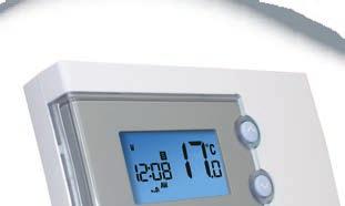
4 INTRODUCTION A programmable thermostat is a transmitter that combines the functions of both a room thermostat and heating controller into a single unit. The programmable thermostat is used to switch the heating system in your home on and off as needed. It works by controlling the temperature according to a series of programmed settings that take effect at different times of the day. The RT505TX from Salus Controls is a stylish and accurate 5/2 or 7 day programmable electronic thermostat with a large, easy to read Liquid Crystal Display (LCD). This programmable thermostat can replace most common residential thermostats and is designed to be used with electric, gas or oil heating control systems. Unlike ordinary single unit design thermostats, this is a new type of thermostat separating the operational functions into two units. The Receiver is used for wiring connections and heat on/off control. The thermostat provides the user interface and temperature sensing / control. The two units are linked together by a Radio Frequency (RF) signal. Features 5/2 or 7 day programming flexibility Built-in start up programming for quick installation Frost protection Large, easy to read LCD with blue backlight Boiler on symbol Easy to use programming User friendly INSTALLATION Please read the important safety information at the start of this manual before you begin to install the device. The RT505TX can be used in any convenient location by using the included stand, or can be easily installed in a fixed position using the industry standard back plate supplied with the unit this is used purely for mounting purposes, as no wiring is needed for the RT505TX. The back plate can be mounted directly to the wall surface. 4 RT505TX INSTRUCTION MANUAL
5 The ideal position to locate the RT505TX thermostat is about 1.5m above floor level. It should be mounted in a location where the thermostat is accessible, reasonably lit and free from extremes of temperature and draughts. Do not mount the thermostat on an outside wall, above a radiator or in a location where it may be subjected to direct sunlight. To ensure trouble free operation of the Radio Frequency (RF) signal, always ensure that the programmable thermostat is mounted away from any possible sources of interference (such as radios, TV sets, computers, etc.), and is not mounted on or in close proximity to large metal objects. Installing the RT505TX in enclosed areas such as cellars and basements is not recommended. AFTER INSTALLATION The following table shows the settings of the RT505TX programmable thermostat after Power on, or after RESET is pressed: Function Status After Reset or Power On Operation Mode Normal mode Room Temperature 22.0 C, updated within 5 seconds C indicator On Clock 12:00 AM/PM indicator AM Day of Week indicator M Program Default factory setting Set Point Temperature Default factory setting Program Number indicator 1 SET indicator Off PROG indicator Off Frost Protection indicator Off Heat indicator Off Low-Battery Warning indicator Off, updated within 5 seconds Output Relay Off After Power on, the thermostat will operate in Normal mode (Normal mode is when the thermostat is displaying the room temperature): The set point temperature is reset to the default setting The room temperature display is updated within 5 seconds The control process starts The programme number is updated to indicate the running program RT505TX INSTRUCTION MANUAL 5

6 If the Reset Button is pressed, the RT505TX will behave in the same way as described above, except that any previously saved user settings stored in the internal memory will be deleted and overwritten with the default settings, and all programmable thermostat control settings will be returned to default values. USER INTERFACE AND CONTROLS The status and operation of the RT505TX is clearly shown on the large backlit Liquid Crystal Display (LCD). This display allows the user to see at a glance the current status of the heating system, the current time and day of the week, as well as a clear indication of the current room temperature. There are few user controls for the RT505TX, making the programmable thermostat very easy to operate. These controls are shown below, along with a description of each of their functions. USER CONTROL FUNCTION SUMMARY Key / Operation Symbol Functions UP key Increases the selected setting DOWN key Decreases the selected setting BACKLIGHT / Manually turns on the LCD backlight FROST key for 5 seconds, or activates / deactivates Frost Protection SELECT key Selects a clock or programme setting SET key RESET button Sets a clock or programme setting Resets the programmable thermostat to default (original factory) settings 6 RT505TX INSTRUCTION MANUAL
7 OPERATION The RT505TX is configured and adjusted by the use of a minimal number of user controls, and an intuitive user interface. The backlit Liquid Crystal Display (LCD) gives a highly visible, easily readable indication of the programmable thermostat status. SETTING THE TIME Press and hold SET and SELECT when the RT505TX is in Normal mode for a few seconds to enter the Clock setting mode. Release both keys and the display will look like the image below: The Time and Day are displayed along with a SET indicator, with all other indicators cleared from the display. The hour part of the time is flashing to indicate that it is the currently selected item and is ready to be adjusted. Press the UP or DOWN keys to increase or decrease the hour setting the selected item will stop flashing while a key is pressed, and will resume flashing when you release the key. Press the SELECT key to select the minutes section of the time. Set the minutes in the same way as the hour by using the UP and DOWN keys. Press SELECT again to select the Day, and again change the setting with the UP and DOWN keys. Press the SET key to confirm the new time and day settings. This will store the changes and return the RT505TX to Normal mode. The RT505TX thermostat will also return to Normal mode (and save the clock settings) if no keys are pressed for more than 15 seconds. RT505TX INSTRUCTION MANUAL 7

 is made by changing the jumper setting on the rear of the RT505TX thermostat, as previously described within the Installation section of this")
8 PROGRAMMING THE RT505TX The RT505TX offers great versatility with its programming options, allowing the user to programme the unit to operate on a 5/2 or 7 day control cycle. The programmable thermostat has a default set of Programmes that have been designed to meet the needs of most users. If these default programmes are not suitable for your particular situation, reprogramming the RT505TX with your own settings is a very straightforward operation. Selection of the default programming mode (5/2 or 7 day) is made by changing the jumper setting on the rear of the RT505TX thermostat, as previously described within the Installation section of this manual. 5/2 DAY MODE 5/2 day mode is the default programming mode for the RT505TX. With this mode selected, five different sets of time and set point temperatures can be set for Weekdays or Weekends. To review or change a programme, press the SET key when the RT505TX is in Normal mode. This will change the unit status to Programme Setting mode. The LCD display will display programme number 1 and SET PROG, with all other indicators cleared. The weekdays will be flashing to indicate they are the selected item and are ready to be adjusted: Press the UP or DOWN key to select the programme set for either Weekday or Weekend to be reviewed or adjusted. Pressing the SET key at any time when in programming mode will return the RT505TX into Normal mode. Press the SELECT key to confirm the Weekday or Weekend selection. Once this is set, the Hour will flash to indicate that it is the selected item and is the next item to be adjusted: 8 RT505TX INSTRUCTION MANUAL


9 Press the UP or DOWN key to adjust the hour setting to the desired value, and confirm your selection by pressing the SELECT key. Pressing the SELECT key allows you to step through each of the items to be reviewed or adjusted within the programmes in the following sequence: Programme Function Sequence 1 6am 00 21ºC 2 8am 00 14ºC 3 4pm 00 21ºC 4 6pm 00 21ºC 5 10pm 00 14ºC before then allowing you to cycle back to Programme 1. Pressing the SET key at any time will confirm the setting and return to the programme set selection. 7 DAY MODE The RT505TX also offers a 7 day programming mode, which allows you to programme five different sets of time and set point temperatures for each day of the week to give a total of 35 separate programme settings. To review or change a programme, press the SET key when the RT505TX is in Normal mode. This will change the unit status to Programme Setting mode. The LCD display will display programme number 1 and SET PROG, with all other indicators cleared. The weekdays will be flashing to indicate they are the selected item and are ready to be adjusted. Press the UP or DOWN key to change the display to indicate the single day you want to programme: Pressing the SET key at any time when in programming mode will return the RT505TX into Normal mode. Press the SELECT key to confirm the Day selection. Once this is set, the Hour will flash to indicate that it is the selected item and is the next item to be adjusted: RT505TX INSTRUCTION MANUAL 9
10 Press the UP or DOWN key to adjust the hour setting to the desired value, and confirm your selection by pressing the SELECT key. Pressing the SELECT key allows you to step through each of the items to be reviewed or adjusted within the programmes in the following sequence: Programme Function Sequence 1 6am 00 21ºC 2 8am 00 14ºC 3 4pm 00 21ºC 4 6pm 00 21ºC 5 10pm 00 14ºC before then allowing you to cycle back to Programme 1. Pressing the SET key at any time will confirm the setting and return to the programme set selection. Each programme for all the other days of the week is set in exactly the same way just repeat the steps shown above, after entering programming mode and selecting the day you want to programme. Regardless of which programming mode the RT505TX is set for (5/2 or 7 day), not pressing any keys for 15 seconds will automatically save any programming changes and exit to Normal mode. You can also review or change programme settings when Frost Protection is enabled. FROST PROTECTION To enable the Frost Protection mode, press and hold the BACKLIGHT / FROST button for three seconds with the RT505TX in Normal mode. Once Frost Protection is enabled, the set point temperature is automatically set to 5 C to provide protection from the risk of freezing. Whenever Frost Protection is activated, the Frost Protection indicator will flash in the sequence shown below: While Frost Protection is activated, it will override any programme settings until the mode is changed. To turn off Frost Protection mode, press and hold the BACKLIGHT / FROST button for three seconds. 10 RT505TX INSTRUCTION MANUAL


11 REVIEWING SET POINT TEMPERATURE You can view the set point temperature at any time by pressing either the UP or DOWN key. When any programme is running, the LCD display will show the programme set point temperature with the SET indicator displayed: When operating in Frost Protection mode, the LCD display will show a reading of 5 C and also display the Frost Protection indicator: When operating in Temporary Override mode, the LCD display will show the temporary set point temperature: To exit from the set point review, press any key except the UP or DOWN keys, or don t press any keys for approximately four seconds either of these actions will return the RT505TX to Normal mode. TEMPORARY OVERRIDE It is possible to temporarily override the current set temperature of the RT505TX. There are two ways to do this: While reviewing set point temperature: Pressing the UP or DOWN key while reviewing the set point temperature will increase or decrease the set point temperature in 0.5 C steps. In Normal mode: press and hold either the UP or DOWN key to display the set point temperature. After two seconds, the RT505TX will enter Temporary Override mode and allow increase or decrease of the set point temperature. If the key is released within two seconds then you will only be able to review the set point temperature. RT505TX INSTRUCTION MANUAL 11

12 Once in Temporary Override mode, the clock and day are displayed, along with the SET indicator; all other indicators are cleared from the display. The set point temperature will flash to indicate that it can be changed: Pressing the UP or DOWN key will increase or decrease the set point temperature in 0.5 C steps - the set point temperature can be adjusted within a set range or 10 C to 35 C. You can press SET at any time to confirm the new Temporary Override setting and return to Normal mode, or press no keys at all and wait approximately four seconds. Temporary Override mode remains active until the clock or programme settings are adjusted, Frost Protection is activated or the next programme time / temperature set point is reached. 12 RT505TX INSTRUCTION MANUAL


 so that the jumper settings match the settings made on the receiver: Jumper Caps For full instructions on pairing the RXRT505")
13 SETTING UP RF COMMUNICATION WITH YOUR RECEIVER RXRT505(ONLY) After you have switched the above receiver on, the thermostat will automatically pair. When the red LED stops flashing, the unit has successfully paired. Receiver DIP Switches If you have difficulty in pairing the thermostat, we recommend changing the address codes in the thermostat and the receiver. To adjust the RF address code of the receiver, simply push up one or more of the 5 DIP switch levers on the DIP switch bank located on the back of the receiver (the levers are numbered 1 to 5 from bottom to top, as shown in the picture left), and then make a note of the setting of each switch: To adjust the RF address code of the thermostat, remove one or more of the jumper caps located on the back of the unit (labelled 1,2,3,4 and 5, and shown in the picture left) so that the jumper settings match the settings made on the receiver: Jumper Caps For full instructions on pairing the RXRT505 see page 7 of the receiver manual. RXVBC605, RXWBC605,RXBC605 & RXST625 To enter pairing mode press and hold SELECT for 3 sec and the thermostat will show 10SY (see right) once the thermostat is in pairing mode press and hold the sync button on the receiver (see page 14) wait for the red LED on receiver to change state then press any key to cancel and return to the main screen. RT505TX INSTRUCTION MANUAL 13


14 LOCATION OF SYNC BUTTONS ON RECEIVERS RXBC605 Sync Button For full instructions on pairing the receiver refer to the RXBC605 manual. Sync Button RXST625 Press reset button first For full instructions on pairing the receiver refer to page 9 of the RXST625 manual. RXVBC605 Sync Button For full instructions on pairing the receiver refer to page 16 of the RXVBC605 manual. RXWBC605 Sync Button For full instructions on pairing the receiver refer to page 23 of the RXWBC605 manual. 14 RT505TX INSTRUCTION MANUAL
15 TESTING THE RF TRANSMISSION 1. Press the UP button on the thermostat until the set point temperature is higher than room temperature by a few degrees. 2. Wait for a few seconds. The boiler on (heat call) indicator should appear on the bottom left of the LCD on the thermostat. 3. Check the LED on the receiver unit - it should be illuminated. 4. Press the DOWN button to adjust the set point temperature to be lower than room temperature. 5. Wait for a few seconds, and the boiler on (heat call) indicator should disappear and the LED should go out. OTHER FUNCTIONS AND CONTROLS Backlight The backlight of the RT505TX is switched on automatically whenever any of the keys are pressed. The backlight will remain illuminated for approximately 5 seconds after the last key press, except if you are changing settings within the Clock, Programme or Temporary Override modes in this case, the backlight will remain illuminated throughout the setting change process. The backlight will not illuminate if the RT505TX battery is low. Battery Status The RT505TX checks the battery voltage frequently during normal operation. If the battery voltage is sensed as being low (this is normally when the battery voltage falls to a level of around 2.6V), the low battery indicator will be displayed on the screen. Although the programmable thermostat will continue to operate normally at this stage, you should replace the batteries as soon as possible to prevent any possible operating problems. Reset Button The Reset Button is provided as a way to restore the programmable thermostat to its default factory settings. Pressing this button will delete any previously entered settings. RT505TX INSTRUCTION MANUAL 15
16 Sleep Mode By pressing both the UP and DOWN keys together, the RT505TX will enter SLEEP mode. In this mode, all the RT505TX functions will be paused to save battery power, with the exception of the clock which will continue to run in the background. While in SLEEP mode: The LCD display will be blank. All output from the thermostat will be turned off immediately. Press any key to wake up the RT505TX and cancel SLEEP mode. ENERGY TIP One way to set and use your room thermostat is to find the lowest temperature setting that you are comfortable with, and then leave it set at this temperature. You can do this by setting the room thermostat to a low temperature, (for example 17 C) and then increasing the setting by one degree each day until you are comfortable with the room temperature - you won t have to adjust the thermostat further, as adjustment above this setting will waste energy - a 1 C increase in temperature is equal to 3% of your heating costs. MAINTENANCE The RT505TX programmable thermostat requires no special maintenance. Periodically, the outer casing can be wiped clean using a dry cloth (please DO NOT use solvents, polishes, detergents or abrasive cleaners, as these can damage the thermostat). There are no user serviceable parts within the unit; any servicing or repairs should only be carried out by Salus Controls or their appointed agents. Should the RT505TX programmable thermostat fail to function correctly, check: The batteries are the correct type, fitted correctly and are not exhausted - fit new batteries if in doubt. Heating system is switched on. The RT505TX receiver is switched on. If the RT505TX is still not functioning correctly, press the Reset Button. WARRANTY Salus Controls warrants that this product will be free from any defect in materials or workmanship, and shall perform in accordance with its specification, for a period of two years from the date of purchase. Salus Controls sole liability for breach of this warranty will be (at its option) to repair or replace the defective product. 16 RT505TX INSTRUCTION MANUAL
17 PRODUCT SPECIFICATION Model: RT505TX Type: Electronic programmable thermostat, designed for RF heating applications. Frequency 868 MHz Programming Programming Modes: Number of Programmes: Override Facility: User selectable for 5/2 or 7 day option Five (5) user programmes plus factory default programme. User selectable programme override facility. Default Programmes Programme Output Weekday Weekend 1 ON 6:00 AM 6:00 AM TEMP 21 ºC 21 ºC 2 ON 8:00 AM 8:00 AM TEMP 14 ºC 14 ºC 3 ON 4:00 PM 4:00 PM TEMP 21 ºC 21 ºC 4 ON 6:00 PM 6:00 PM TEMP 21 ºC 21 ºC 5 ON 10:00 PM 10:00 PM TEMP 14 ºC 14 ºC Temperature Scale: Celsius Range: 5 ºC to 35 ºC Resolution: 0.5 ºC Tolerance: Less than ± 0.5 ºC at 25 ºC Display Range: 5.0 ºC to 45.0 ºC Display Resolution: 0.5 ºC Setpoint Temperature Range: 5 ºC to 35 ºC Measured Air Temperature Range: 5 ºC to 45 ºC (Displayed on LCD) If room temp is higher than 45C,will show HI on the LCD, if less than 5C will show LO on the LCD Thermostat Power Source: 2 x AA alkaline batteries (don t use rechargeable batteries) RT505TX INSTRUCTION MANUAL 17
18 Clock Accuracy: Display: ± 1 minute per month 12 hour Frost Protection Setting: 5 ºC Environment Operating Temperature: 0 ºC to + 40 ºC Storage Temperature: - 20 ºC to + 60 ºC 18 RT505TX INSTRUCTION MANUAL
19 RT505TX Warranty Salus Controls warrants that this product will be free from any defect in materials or workmanship, and shall perform in accordance with its specification, for a period of two years from the date of purchase. Salus Controls sole liability for breach of this warranty will be (at its option) to repair or replace the defective product. Customer Name:... Customer Address: Post Code:... Tel No: Engineers Company:... Tel No: Intallation Date:... Engineers Name:... Engineers Signature:... RT505TX INSTRUCTION MANUAL 19

20 Sales: Technical: salus-tech. Tel: Tel: Salus Controls plc, Salus House, Dodworth Business Park South, Whinby Road, Dodworth, Barnsley S75 3SP
Programmable Room Thermostat With RF
 Salus RT500RF Manual:89 10/7/10 23:43 Page 1 Programmable Room Thermostat With RF Instruction Manual Model No RT500RF 2 Salus RT500RF Manual:89 10/7/10 23:43 Page 2 PRODUCT COMPLIANCE This product complies
ST625TX Digital Room Thermostat
 ST625TX Digital Room Thermostat RXBC605 RXST625 RXWBC605 RXVBC605 RXRT505 The ST625TX can be used with any of these receivers 868MHz PRODUCT COMPLIANCE This product complies with the essential requirements
S-Series Digital Thermostat. Instruction Manual Model No ST620RF
 S-Series Digital Thermostat Instruction Manual Model No ST620RF 2 PRODUCT COMPLIANCE SALUS Controls Plc hereby declares that the radio equipment type 868Mhz is in compliance with Directives 1999/5/EC,
Thank you for purchasing this product. If installing for someone else, please ensure that the instructions are handed to the householder.
 Instruction Manual TPSRF51 (957707) - BOSS TM Universal RF Programmable Room Thermostat (Wireless) (7 day, 5/2 day and 24 hour programme options) Thank you for purchasing this product. If installing for
Thank you for purchasing this product. If installing for someone else, please ensure that the instructions are handed to the householder.
 Instruction Manual TPST501 (569568) - BOSS TM Universal mable Room Thermostat (Wired) (7 day, 5/2 day and 24 hour programme options) Thank you for purchasing this product. If installing for someone else,
SCS318. User Instructions. SCS318 comprising of SCS317 7 Day Wireless Programmable Room Thermostat and SSR303 Receiver
 SCS318 User Instructions SCS318 comprising of SCS317 7 Day Wireless Programmable Room Thermostat and SSR303 Receiver Programmable room thermostats are widely recognised as one of the best ways in which
LP20. Installation & User Guide. Dual Channel Programmer. Part number 25039DR
 Dual Channel Programmer Part number 25039DR! For GREENSTAR CDi, GREENSTAR i JUNIOR and GREENSTAR Si MODELS also GREENSTAR i SYSTEM and GREENSTAR CDi SYSTEM MODEL(only when used with the optional integral
1 Channel Multi-Purpose Programmer User Instructions
 ES1247B 1 Channel Multi-Purpose Programmer User Instructions Thank you for choosing ESi Controls. All our products are tested in the UK so we are confident this product will reach you in perfect condition
ULTRA-VANSTAT WIRELESS PROGRAMMABLE THERMOSTAT FOR CARAVANS
 ULTRA-VANSTAT WIRELESS PROGRAMMABLE THERMOSTAT FOR CARAVANS NOT SUPPLIED PROGRAMMER / TRANSMITTER RECEIVER THIS DOMESTIC STYLE WIRELESS 7 DAY PROGRAMMABLE HEATER CONTROL REPLACES THE TRUMA ULTRAHEAT SWITCH
Thank you for purchasing this product. If installing for someone else, please ensure that the instructions are handed to the householder.
 Instruction Manual TPSE201 (181422) - BOSS TM Universal Programmer TPSE101 (569565) - BOSS TM Universal Timeswitch Thank you for purchasing this product. If installing for someone else, please ensure that
Comfort System T-32-P Universal Thermostat. Operation Manual
 TM Comfort System T-32-P Universal Thermostat TM O Operation Manual Your new Comfort System T-32-P Universal Thermostat has been built using the highest quality components and design currently available.
Radio Thermostat Clock
 Radio Thermostat Clock Installation & User Instructions Part number: ZU0800009 80.10.1375.7_feeling_ks_fer_en.indd 1 18.04.2013 11:25:42 Table of contents Safety instructions... 3 Product details... 4
7 Day Digital Programmer
 7 Day Digital Programmer Cat. No. TRT034 Operating & Installation Instructions What is a programmer?...an explanation for householders Programmers allow you to set On and Off time periods. Some models
Installation & Programming Manual. Please read before using this timer.
 Installation & Programming Manual Please read before using this timer. Warning! This unit operates using two fresh, high-quality AA alkaline batteries.batteries must be installed for unit to operate. USE
EN Wireless programmable thermostat
 EN Wireless programmable thermostat Contents 1. Installation... 31 2. Description... 32 EN 3. Wireless association... 33 4. Configuration... 34 CF01 - Correcting the temperature measured... 34 CF02 - Temperature
RAMMER INSTRUCTION MANUAL FITTING & OPERATING INSTRUCTIONS NEL PROGRAMMER. NSTAR Si MODELS
 RAMMER NEL PROGRAMMER NSTAR Si MODELS INSTRUCTION MANUAL FITTING & OPERATING INSTRUCTIONS .,,' CONTACT INFORMATION MANUAL INFORMATION WORCESTER BOSCH: TECHNICAL: 08705266241 SERVICE: 08547 256206 SPARES:
TDDFM14 OWNER S MANUAL
 TDDFM14 OWNER S MANUAL Table of Contents 3 Installation Features System Selector Switches 6 10 Connecting Wires and Mounting Thermostat 10 Operation (Programming) Programming/Setting Clock Personal Program
SINGLE ZONE CLIMATE ZONING SYSTEM. Technical Manual. Polyaire Pty Ltd
 SINGLE ZONE CLIMATE ZONING SYSTEM Technical Manual Polyaire Pty Ltd 11-13 White Road GEPPS CROSS South Australia, 5094 Tel: (08) 8349 8466 Fax: (08) 8349 8446 www.polyaire.com.au CONTENTS Features 1 Application
SR - 516D DESK TOP DMX REMOTE STATION. Version: Date: 05/16/2013
 SR - 516D DESK TOP DMX REMOTE STATION Version: 1.10 Date: 05/16/2013 Page 2 of 10 TABLE OF CONTENTS DESCRIPTION 3 POWER REQUIREMENTS 3 INSTALLATION 3 CONNECTIONS 3 POWER CONNECTIONS 3 DMX CONNECTIONS 3
ST9100C User Guide. Features
 Features Easy to use slider and buttons combined with LoT Technology and an OK button, allows you to confi rm changes and stay in control. PLEASE RESPECT YOUR ENVIRONMENT! Take care to dispose of this
24 Hour & 7 Day Digital Immersion Heater Timeswitch Article
 24 Hour & 7 Day Digital Immersion Heater Timeswitch Article 943 320 Large 24 hour clock/programme display. Tough flame retardant bezel 1 Enables clock time to be changed. Used to review and change timer
ZoneTouch V2 Zone Control System User Manual
 ZoneTouch V2 Zone Control System User Manual www.polyaire.com.au 2014 Polyaire Pty Ltd II ZONEMASTER ZONETOUCH V2 ZONE CONTROL SYSTEM - User Manual TABLE OF CONTENTS 1) Features 2 2) Wall Controller Layout
ServicePlus S17R Series 2 User Operating Instructions
 ServicePlus S17R Series 2 User Operating Instructions Single Channel Timeswitch The Horstmann ServicePlus S17R timeswitch will allow up to 3 ON/ settings per 24 hours on a weekly schedule and has a 1 hour
EC5415B. B-Tronic EasyControl. Assembly and Operating Instructions. Wall/hand-held transmitter, 15-channel, bidirectional
 B-Tronic EasyControl EC5415B en Assembly and Operating Instructions Wall/hand-held transmitter, 15-channel, bidirectional Important information for: Fitters / Electricians / Users Please forward accordingly!
WDK-2500-STROBE. User Guide
 WDK-2500-STROBE User Guide Warning: This device complies with Part 15 of the FCC rules, operation of this device is subject to the following conditions: 1. This device may not cause harmful interference.
LCD VALUE SERIES (32 inches)
") LCD VALUE SERIES (32 inches) http://www.orionimages.com All contents of this document may change without prior notice, and actual product appearance may differ from that depicted herein 1. SAFETY INSTRUCTION
LCD VALUE SERIES (32 inches) http://www.orionimages.com All contents of this document may change without prior notice, and actual product appearance may differ from that depicted herein 1. SAFETY INSTRUCTION
Quick Start Guide. Handheld Transmitter HHa-941. Digital Hybrid Wireless US Patent 7,225,135
 Quick Start Guide Handheld Transmitter HHa-941 Digital Hybrid Wireless US Patent 7,225,135 For FCC Part 74 licensed operators Fill in for your records: Serial Number: Purchase Date: This guide is intended
CH1 CH2 CH3 CH4. Master /Fade CH5. 600s CH6. 60s SC1 SC2 SC4 SC3 SC5. SC6 Off/Pro. AL Fade 6 Pro. User guide
 1 1 CH1 CH2 1 1 CH4 CH 1 CH3 6s Master /Fade CH6 1 SC1 6s SC4 SC2 SC SC3 SC6 Off/Pro AL Fade 6 Pro User guide CONTENTS INTRODUCTION...2 Welcome 2 Safety 2 Supplied items 3 INSTALLATION...4 Mounting 4
TP7001 Range Electronic 7 Day Programmable Room Thermostat. Danfoss Heating. Installation Guide
 TP7001 Range Electronic 7 Day Programmable Room Thermostat Danfoss Heating Installation Guide For a large print version of these instructions please call Marketing on 0845 121 7400. Certification Mark
DCL9AW. User Manual. English
 DCL9AW User Manual English PRECAUTIONS Information for users applicable in European Union countries 1 Information for users applicable in United States of America 1 Installation 1 Power connection 1 Maintenance
Battery Operated Controllers
 ALL SEASONAL ADJUSTMENT 1 Battery Operated Controllers Owner s Manual and Programming Instructions RUN PRG SENSOR BYPASS SYSTEM OFF CURRENT TIME/DAY ACTIVE MANUAL-ALL STATIONS START TIMES MANUAL-ONE STATION
MONOPRICE. 27" UHD IPS 4K Ultra Slim Aluminum Monitor. Quick User's Guide P/N 24658
 MONOPRICE 27" UHD IPS 4K Ultra Slim Aluminum Monitor P/N 24658 Quick User's Guide SAFETY WARNINGS AND GUIDELINES Please read this entire manual before using this device, paying extra attention to these
2 Verify that the green light
 Getting started with your SmartRooms Comfort Controller is as easy as... 1,2, 1 Cancel/Occ. to put Comfort Controller in manual mode 2 Verify that the green light is on indicating manual mode. SmartRooms
MODEL HA07 - MASTER CONTROLLER INSTRUCTIONS
 Thank you for purchasing Intermatic s Home Settings devices. With these products you can reliably and remotely control lighting and appliances. The outstanding features of the Home Settings program include:
CP017 USER OPERATING INSTRUCTIONS. Single Channel Timeswitch
 CP017 USER OPERATING INSTRUCTIONS Single Channel Timeswitch The CP017 timeswitch will allow up to 3 ON/ settings per day for each day of the week and has a 1 hour manual boost and advance button to temporarily
DVB-T305. Freeview HD Receiver Récepteur TNT HD DVB-T Receiver Ricevitore TDT HD Sintonizador TDT HD EN FR DE IT ES
 DVB-T305 August International Ltd United Kingdom Telephone:+ (0) 85 250 0586 www.augustint.com EN FR DE IT ES Freeview HD Receiver Récepteur TNT HD DVB-T Receiver Ricevitore TDT HD Sintonizador TDT HD
2 CHANNEL RECEIVER DISPLAY POTENTIOMETER COM2 NC2 NO2
 2 CHANNEL RECEIVER RECTSHIVE915-DX Please read this manual carefully before installing the product. 1 DESCRIPTION Receiver Rolling Code, 2 channels with dry contact relay output 20A a 12 Vdc. Programming
7 DAY DIGITAL LIGHTSWITCH WITH OPTIONAL DUSK START INSTALLATION & OPERATING. Cat No. ZV700 INSTRUCTIONS
 7 DAY DIGITAL LIGHTSWITCH WITH OPTIAL DUSK START Cat No. ZV700 INSTALLATI & OPERATING INSTRUCTIS ZV700 - Lower Flap Closed ZV700 - Lower Flap Open 1 Rocker switch - used in manual operation Supply LED
ChannelPlus H17XL Series 2 User Operating Instructions
 ChannelPlus H17XL Series 2 User Operating Instructions Single Channel 7 day Timeswitch The ChannelPlus family of electronic programmers offer a range of advanced features coupled with simplified menu driven
Waterline Room Controller - Type WLCT3
 INSTRUCTIONS Introduction Room controller type WLCT3 is a 4-event programmable controller used to control areas with underfloor heating or special features of a WLM3 installation. The standard WLCT3 can
INSTRUCTION & INSTALLATION GUIDE
 Digital electric radiator INSTRUCTION & INSTALLATION GUIDE 2 Introduction harmoni digital electric radiators are programmable with an exclusive electronic temperature programmer and manufactured with quality
CP027. User Operating Instructions. Two Channel Central Heating and Hot Water Programmer
 CP027 User Operating Instructions Two Channel Central Heating and Hot Water r The CP027 two channel programmer gives independent control over hot water and heating with up to 3 ON/ settings for each day
VITEK VTM-TLM191 VTM-TLM240
 VTM-TLM191 VTM-TLM240 19 & 24 Professional LED Monitors with HDMI, VGA, and Looping BNC VITEK FEATURES 19 & 24 Wide Screen LED Display Panel HDMI, VGA, and Looping BNC Composite Video Inputs & Stereo Audio
Ducasa Digital Programmer
 Ducasa Digital Programmer Hand Held Remote Control Unit Instructions for Operation and Programming (Read these instructions carefully and retain for further reference.) Model: DUCASA REMOTE CONTROLLER
ATTACHING & REMOVING THE BASE
 TV53DB ATTACHING & REMOVING THE BASE 1. To install or remove the neck, screw in or remove the 4 screws indicated in the picture. 2. To install the base, place the display unit flat on a table. Afterwards
Caller Display 1000 User Guide
 Please note that batteries are not included. You will need 4x AAA batteries YOU MUST SUBSCRIBE TO THE CALLER DISPLAY SERVICE OFFERED BY YOUR NETWORK PROVIDER TO DISPLAY CALLER INFORMATION. A QUARTERLY
STAGE SETTER-8. User Instructions. Elation Professional 4295 Charter Street Los Angeles Ca
 Introduction STAGE SETTER-8 User Instructions Introduction: Thank you for purchasing the Elation Professional Stage Setter 8. To optimize the performance of this product, please read these operating instructions
Inserting the batteries. Basic settings of the remote control
 Inserting the batteries Procedure prior to first use or when changing batteries Remove the back plate to expose the battery tray. Insert 2 x AA 1.5V alkaline batteries. Ensure the polarity of the batteries
Be sure to run the vehicle engine while using this unit to avoid battery exhaustion.
 CAUTION: TO REDUCE THE RISK OF ELECTRIC SHOCK DO NOT REMOVE COVER (OR BACK) NO USER-SERVICEABLE PARTS INSIDE REFER SERVICING TO QUALIFIED SERVICE PERSONNE; Please Read all of these instructions regarding
OPERATING YOUR SYSTEM WITH MX-850
 OPERATING YOUR SYSTEM WITH MX-850 This remote control was Custom Programmed for you by: For questions about your Custom Programming call: Custom Programming of a complex home theater and/or a multi-room
LF-IRX. 12 Month Limited Warranty LF-IRX. Remote Control Extender. Owner s manual. For customer service and technical information::
 12 Month Limited Warranty Audiovox Electronics Corporation (the company) warrants to the original purchaser of this product that should this product or any part thereof, under normal use and conditions,
RD RACK MOUNT DIMMER OWNERS MANUAL VERSION /09/2011
 RD - 122 RACK MOUNT DIMMER OWNERS MANUAL VERSION 1.3 03/09/2011 Page 2 of 14 TABLE OF CONTENTS UNIT DESCRIPTION AND FUNCTIONS 3 POWER REQUIREMENTS 3 INSTALLATION 3 PLACEMENT 3 POWER CONNECTIONS 3 OUTPUT
APOLO DC B Electric Thermal Radiators
 APOLO DC B Electric Thermal Radiators Large LCD control Display Daily and weekly programming INSTRUCTIONS FOR USE, INSTALLATION AND ASSEMBLY 1 INDEX 1. INTRODUCTION... 1 2. LOCATION... 1 3. ELECTRIC CONNECTION...
MP-7424 Football Scoreboard with MP5000 Console
 MP-7424 Football Scoreboard with MP5000 Console With additional instructions for Track and Soccer Operator s Manual Volume VII Rev. 10/17/07 Table of Contents Table of Contents...2 1.0 Keypad Console...3
10.4" LCD Monitor with Aluminum Front Bezel YPM1040PHB
 SPECIFICATION FOR APPROVAL M0DEL: 10.4" LCD Monitor with Aluminum Front Bezel YPM1040PHB BASE MODEL Customer's Confirmation Approved by: Reviewed by: Prepared by: Supplier's Confirmation Approved by: Reviewed
Users Manual. Stroboscope. September 2014
 820-2 Stroboscope Users Manual September 2014 2014 Fluke Corporation. All rights reserved. Specifications are subject to change without notice. All product names are trademarks of their respective companies.
USER MANUAL. 27 Full HD Widescreen LED Monitor L270E
 USER MANUAL 27 Full HD Widescreen LED Monitor L270E TABLE OF CONTENTS 1 Getting Started 2 Control Panel/ Back Panel 3 On Screen Display 4 Technical Specs 5 Care & Maintenance 6 Troubleshooting 7 Safety
2015 MESA SAFE COMPANY
 2015 MESA SAFE COMPANY CATEGORY PAGE CHECK LIST 2 OPENING YOUR SAFE 3 LOCK-OUT PENALTY 3 USING THE OVERRIDE FUNCTIONS 4 CHANGING THE OVERRIDE 4 CHANGING THE LOCK SETTTINGS 5 SETTING THE DATE & TIME 7 VIEW
WS-6118 ATOMIC CLOCK WITH OUTDOOR WIRELESS TEMPERATURE AND MOON PHASE Instruction Manual
 WS-6118 ATOMIC CLOCK WITH OUTDOOR WIRELESS TEMPERATURE AND MOON PHASE Instruction Manual FEATURES: ATOMIC CLOCK: Hanging holes LCD1 display Function keys LCD2 display Foldable stand WWVB Radio controlled
Operation Guide 6022 ENGLISH
 Operation Guide 6022 Control Panel Reset TEMP UP SET CLOCK PROG2 TIME SET Heat/Cool Mode Switch Fan Switch Target Temp TIME SLOT Time EPA PROGRAM COPY HOLD REVIEW FILTER TEMP DOWN Battery Compartment Statement
Userfriendly Guide. For use with BT s Caller Display and Call Waiting Select Services
 Caller Display 000 Userfriendly Guide For use with BT s Caller Display and Call Waiting Select Services Caller Display and Call Waiting services require set-up by BT or your service provider and connection
User Guide. Centrex Recording Interface
 User Guide Centrex Recording Interface Table of Contents Introduction... 2 The Meridian Business Set... 3 Key Numbering Plan (18 button add-on)... 4 Key Numbering Plan (36 button add-on)... 5 Key Numbering
7 Day Digital Time Switch
 7 Day Digital Time Switch Model: NTT08 Installation & Operating Instructions 1 1. General Information These instructions should be read carefully and retained for further reference and maintenance. 2.
Children cannot always recognize potential hazards properly. This 5.1 system is not designed for operation in a heavy industry environment.
 5.1 FLAT PANEL SPEAKER SYSTEM WITH POWERED SUBWOOFER Table of Contents: SAFETY AND SERVICE... 2 Operational Safety... 2 Location... 2 Ambient Temperature... 3 Electromagnetic Compliance... 3 Service...
Manual. Simrad IS80 Heading Repeater HR80. English
 Manual Simrad IS80 Heading Repeater HR80 English www.simrad-yachting.com A brand by Navico - Leader in Marine Electronics Manual Simrad IS80 Heading Repeater HR80 English Document no: 20223194 Revision:
7 Day Digital Programmer 3 Channel Surface Mount
 7 Day Digital Programmer 3 Channel Surface Mount Model: TRT038N Installation & Operating Instructions 1. General Information These instructions should be read carefully and retained for further reference
TL5024 MEMORY LIGHTING CONSOLE OWNERS MANUAL. Version 1.01
 TL5024 MEMORY LIGHTING CONSOLE OWNERS MANUAL Version 1.01 09/22/2017 Page 2 of 14 SPECIFICATIONS Total channels Operating modes Scene memory Chase 12 or 24 depending on mode 12 channels x 2 manual scenes
WCM-758G. user MANUAL
 SKYVISION WCM-758G WIRELESS 7" MONITOR user MANUAL 2 INTRODUCTION Thank you for choosing Elvid. The Elvid WCM-758G SkyVision is a wireless monitor designed to receive signal from your 5.8 GHz composite
Check our knowledge base at
 USER MANUAL Check our knowledge base at www.paralinx.net/support Copyright 2015 Paralinx LLC All Rights Reserved TABLE OF CONTENTS 1 Important Notice 10 LCD Screen 2 Safety Instructions 11 Indicators 3
SPX-5600 Series. Operations Manual. Suprex Reader Extender - RF Wireless Interface SPX-5600MAN. Page 1 of 20
 SPX-5600 Series Operations Manual Suprex Reader Extender - RF Wireless Interface SPX-5600MAN Page 1 of 20 SPX-5600 Series: Cypress Suprex SPX-5600 Series This manual covers the operation and setup of the
K9123, K9134, K9135 Remote Programming Instructions and Specifications
 K9123, K9134, K9135 Remote Programming Instructions and Specifications 12 Volt Signal Ground Signal Plug Door Push & Hold K9123 K9134 K9135 Before pairing the receiver to the remotes, the receiver must
PROGRAMMABLE THERMOSTAT
 PROGRAMMABLE THERMOSTAT Operating Instructions and Limited Warranty 49-50276 03-11 GE CONTENTS Safety Instructions... 3 Thermostat Overview... 4 Home Screen... 5 Set Heat/Cool Mode... 5 Set Fan Mode...
SINCE User Manual 7 DAY PROGRAMMABLE DIGITAL TIMER MODEL PS-100. The best solutions for automation and protection.
 SINCE 1973 User Manual 7 DAY PROGRAMMABLE DIGITAL TIMER MODEL PS-100 The best solutions for automation and protection www.nassarelectronics.com Description The PS-100 is a 7 day programmable digital timer
USER MANUAL. 27 Full HD Widescreen LED Monitor L27ADS
 USER MANUAL 27 Full HD Widescreen LED Monitor L27ADS TABLE OF CONTENTS 1 Getting Started 2 Control Panel/ Back Panel 3 On Screen Display 4 Technical Specs 5 Care & Maintenance 6 Troubleshooting 7 Safety
Owner's Manual DIGITAL TO ANALOG BROADCAST CONVERTER WITH REMOTE CONTROL. Model: CVD508 PLEASE READ BEFORE OPERATING THIS EQUIPMENT.
 Size: 148.5(W) x 210(H)mm (A5) DIGITAL TO ANALOG BROADCAST CONVERTER WITH REMOTE CONTROL Owner's Manual PLEASE READ BEFORE OPERATING THIS EQUIPMENT. Model: CVD508 FCC NOTICE: To assure continued compliance,
GPS. Quick Start Guide. Model #: Lit# /04-10
 GPS Made Simple! 5 N E V E R G E T L O S T A G A I N Quick Start Guide Model #: 360200 Lit# 98-1586/04-10 Full Instruction Manual available online at: www.bushnell.com/manuals/gps Control & Display Guide
User interface. Abbreviations / Meanings
 RG66012649 User interface Contents Page Abbreviations / Meanings Abbreviations / meanings... 2 Button Identification... 3 On-screen Indicators... 4 Quick Start... 5 Setting the time and day... 5 Changing
TS-4000 Multifunction Thermostat Timer Switch User Manual
 TS-4000 Multifunction Thermostat Timer Switch User Manual 1st Version,April.11,2017 Contents 03 03 04 06 06 08 09 10 10 12 13 17 20 21 23 24 25 26 27 27 Introduction Before first use Safety notes Proper
Lifestyle. Dual Channel Programmer. for heating AND hot water. Installation and User Instructions DUAL CHANNEL ISSA
 Lifestyle Dual Channel Programmer for heating AND hot water Installation and User Instructions DUAL CHANNEL 06490197001 ISSA INSTALLATION INSTRUCTIONS PLEASE NOTE: INSTALLATION MUST ONLY BE CARRIED OUT
LCD Thermometer / Clock S No. 1253
 Installation and Operating Manual LCD Thermometer / Clock S No. 1253 The 3 fold thermometer with crystal clock is purpose build for the mounting in caravans, boats and intervention vehicles. Please read
Rain+Birdt. Landscape Irrigation & Maintenance Remote System. Quick Start Guide 4.00 F G H K 9X. c n. System Components
 Rain+Birdt Landscape Irrigation & Maintenance Remote System Quick Start Guide 4.00 D System Components A Transmitter (TX) B Receiver (RX) C Quick Connect (QC) 6-Pin Quick Connect (QC) for use with ESP-Modular
Aspect 2 Circuit Digital Scene Control
 Aspect 2 Circuit Digital Scene Control S p e c i f i c a t i o n 2 circuits of trailing edge dimming 500W total between the two circuits Both circuits feature independent overload, short-circuit and open-circuit
OPERATION AND MAINTENANCE
 BAS MS/TP Enabled OPERATION AND MAINTENANCE An Company Contents Powering Up For The First Time... 3 Setting MSTP Communication Parameters... 4 Changing the MSTP Address... 4 Changing the BACNET ID... 5
OLS Series Light Sources, OPM Series Optical Power Meters, and Related Test Kits User s Guide
 OLS Series Light Sources, OPM Series Optical Power Meters, and Related Test Kits User s Guide Limited Warranty One Year Limited Warranty All Noyes products are warranted against defective material and
28 4K LED monitor. User Manual M284K
 28 4K LED monitor User Manual M284K CONTENTS Safety Information... 2 What s included..... 4 Getting Started....... 8 Troubleshooting.... 14 Specification.... 15 2 of 15 SAFETY INFORMATION Read these instructions
PREMIUM WIDE ASPECT RATIO LED SERIES (18~23 inches)
") PREMIUM WIDE ASPECT RATIO LED SERIES (18~23 inches) http://www.orionimages.com All contents of this document may change without prior notice, and actual product appearance may differ from that depicted
PREMIUM WIDE ASPECT RATIO LED SERIES (18~23 inches) http://www.orionimages.com All contents of this document may change without prior notice, and actual product appearance may differ from that depicted
Instruction Guide. The TV Jockey Computer Monitor TV Tuner with Remote COMP2VGATVGB. The Professionals Source For Hard-to-Find Computer Parts
 VIDEO ADAPTER The TV Jockey Computer Monitor TV Tuner with Remote COMP2VGATVGB Instruction Guide * Actual product may vary from photo The Professionals Source For Hard-to-Find Computer Parts FCC COMPLIANCE
DSIM-GI Installation Guide Revision P
 Installation Guide Revision P 1. Quick Start Instructions for Single Pilot AGC Operatation 1. With the ADU jumper in Auto position, turn ADU pot to MIN amplifier output level. Then place the ADU jumper
Ambient Weather WS-01 Intelligent Color Changing Temperature Night Light with Ambient Backlight User Manual
 Ambient Weather WS-01 Intelligent Color Changing Temperature Night Light with Ambient Backlight User Manual Table of Contents 1 Introduction... 1 2 Warnings... 2 3 Getting Started... 2 3.1 Parts List...
Controller DMX DC-1224
 Manual Controller DMX DC-1224 Table of Contents 1. Safety instructions... 4 1.1. FOR SAFE AND EFFICIENT OPERATION... 4 3. Overview... 6 3.1. Front view... 6 3.2. Rear view... 9 4. Operation guide... 10
Digital Time Switch. Installation & Operating Instructions
 Digital Time Switch Model: NTT06 24 Hour General Purpose Digital Timer Model: NTT07 7 Day General Purpose Digital Timer Installation & Operating Instructions 1 1. General Information These instructions
Mini Electronic Pulse Massager
 Mini Electronic Pulse Massager UC-029 Operating Manual Contents Introduction...2 Safety warnings....3 Part identification 4 Operating instructions...5 Program schematics....6-8 Recommended use points......8
TRANSCENSION 6-CHANNEL DMX DIMMER PACK (order code: BOTE40) USER MANUAL
 USER MANUAL") www.prolight.co.uk TRANSCENSION 6-CHANNEL PACK (order code: BOTE40) USER MANUAL SAFETY WARNING FOR YOUR OWN SAFETY, PLEASE READ THIS USER MANUAL CAREFULLY BEFORE YOUR INITIAL START-UP! CAUTION! Keep this
www.prolight.co.uk TRANSCENSION 6-CHANNEL PACK (order code: BOTE40) USER MANUAL SAFETY WARNING FOR YOUR OWN SAFETY, PLEASE READ THIS USER MANUAL CAREFULLY BEFORE YOUR INITIAL START-UP! CAUTION! Keep this
Access Control Keypad for MK-DV, JB-DV
 #91173 0406 Access Control Keypad for MK-DV, JB-DV - INSTRUCTIONS - The KVI is a surface mount electronic access control keypad for use with Aiphone s MK-DV or JB-DV video door station. Designed with the
BT Diverse Repeater. User Guide
 BT Diverse Repeater User Guide Section Welcome to your BT Diverse Repeater Range Extender Extends the range in which you can make and receive calls from your existing DECT base station by up to 50m indoors
Operating instructions. Universal timer switch display
 Operating instructions 1. Function The Time Switch display is a system component and is installed in a box as per DIN 49073 (deep box recommended) in conjunction with the Time Switch insert. The unit facilitates
Sprite TL Quick Start Guide
 Sprite TL Quick Start Guide with 115 VAC Power Cord and 4-Conductor Signal Cable Reference Manual Sprite TL Online and downloadable Product Manuals and Quick Start Guides are available at www.hydrosystemsco.com
For use with QED and hardwired control panels ONLY!
 K3129-5 10/98 6128WL Keypad/Receiver INSTALLATION INSTRUCTIONS For use with QED and hardwired control panels ONLY! General Information The 6128WL Keypad/Receiver is a combination unit. It replaces a 6128
Vocia WR-1. Operation Manual
 Vocia WR-1 Operation Manual January 2012 Biamp Systems, 9300 SW Gemini Drive, Beaverton, Oregon 97008 U.S.A. (503) 641-7287 www.biamp.com TABLE OF CONTENTS VOCIA WALL REMOTE 1 (WR-1) FEATURES....3 FRONT
Sample BD Tech Concepts LLC
 XYZ Corp. Fry Controller FC-1234 Operating Specification Copyright 2014 Brian Dunn BD Tech Concepts LLC Contents Last Modified: 00/00/0000 Introduction 2 Interface 3 Idle 5 Cooking Cycle 5 Displaying and