LabView Exercises: Part III
|
|
|
- Ophelia Ramsey
- 5 years ago
- Views:
Transcription

1 Physics 3100 Electronics, Fall 2008, Digital Circuits 1 LabView Exercises: Part III The working VIs should be handed in to the TA at the end of the lab. This is a lab under development so we may experience some glitches the first time through. Please bear with us. Initializing the NI 6251 and SCC68s The NI 6251 Multifunction I/O allows rapid analog to digital conversion and input to the computer as well as rapid Digital to Analog conversion and output from the computer via the USB port. It also provides digital I/O capabilities as well as some timer functions. We have interfaced this device to an SCC68 box containing analog and digital buffers to protect the sensitive inputs and outputs of the These two devices are connected by a 37 pin cable. The banana plugs and BNC connectors which we have added to the SCC68 provide a convenient interface to the student s experiments. Exercise 1: Using MAX to initialize the NI 6251 The first time this hardware is used on any given computer it must be initialized. The Measurement and Automation Explorer (MAX) software provides an easy way to identify the NI hardware connected to the computer. Follow the following steps: 1) Once you are sure that the NI 6251 and SCC68 are correctly connected and powered on, launch MAX by double clicking on its icon on the desk-top.
. Doubleclick on NI-DAQmx Devices.")
2 Physics 3100 Electronics, Fall 2008, Digital Circuits 2 2) On the left side of the window which MAX opens you will see a column entitled Configuration. Double-click on Devices and Interfaces to expand the sub-category (or click on the + box). Doubleclick on NI-DAQmx Devices. The expanded sub-category should show an NI USB-6251 (Mass Termination): Dev xx (there will only be one such entry for your computer). 3) Click on the NI USB 6251 entry (it should be showing a green circuit board on the left to indicate that it is connected). 4) Click on the Properties tab at the centre top of the window. This will open a Device Properties dialog box. On the Accessory tab which is displayed there will be a check-list. Scroll down the list to find SCC-68 as shown. Click on SCC-68 and on OK.


3 Physics 3100 Electronics, Fall 2008, Digital Circuits 3 5) Now click on the tab Test Panels.. at the top of the window to display the test panel dialog box. This panel will allow you to test the functioning of your NI 6251 and the SCC 68 which is connected

4 Physics 3100 Electronics, Fall 2008, Digital Circuits 4 to it. 6) Begin by testing the Analog Input channels (the first tab). The channels which are connected via the SCC 68 are Dev*/ai4 and Dev*/ai12. First select Channel Name Dev*/ai4 and set up the test for Continuous Mode, and the RSE Input Configuration, as shown below. If there is no signal source connected to the BNC connector labelled AI0 on the SCC 68 the display chart should show noise similar to that displayed on the figure when you press Start. 6) Connect the output from your function generator to the input AI0 BNC connector. Since the acquisition rate specified in the test panel is 1000 Hz (see figure above) your function generator frequency should be set to a frequency which is less than 500 Hz. (You must sample at least twice as fast as the highest frequency of interest..this is the sampling theorem). Choose a suitably low frequency. Also, the input should have an amplitude less than 10 volts. If the output displayed on the panel is as you d expect, click on STOP and perform the same test on Channel Name Dev*/ai12 using the same set up parameters. If both channels pass this test, move on to the Analog Output test by clicking on the Analog Output tab at the top of the window. 7) Connect the Dev*/ao0 output from BNC AO0 on the SCC 68 to your oscilloscope. Set up channel 0 as shown below

5 Physics 3100 Electronics, Fall 2008, Digital Circuits 5 You should see a sine wave on your oscilloscope. Change the amplitude and frequency to verify that everything is working correctly then repeat the test using Dev*/ao0 and the AO1 BNC connector. 8) Finally, click on the Digital I/O tab at the top of the window and test the 4 output and 4 input digital lines. These are connected to the coloured banana jacks and are labelled DO0 through DO3 and DI0 through DI3. Set up the test panel as shown below, using port1 and click on Start. Lines 0 through 3 are assigned as inputs while those from 4 through 7 are outputs. All 8 lines are connected internally to pull-up resistors so the 4 input lines )bits 0 through 3) show up as high unless something pulls them down. Connect any of the 4 lines DI0 through DI3 to ground using a wire with banana plugs and the corresponding circular green light on the test panel should go dark.. Next, connect one of the output lines DO0 through DO3 to an LED (use a 1 kω series resistor). Then using the test panel s slide switches you should be able to turn the LED on and off. This demonstrates that the digital I/O is working. After you have completed these tests you may continue with the next exercise.

6 Physics 3100 Electronics, Fall 2008, Digital Circuits 6 Exercise 2: Data Acquisition Using the NI USB-6251 plus SCC 68 The National Instruments USB-6251 provides 16 single-ended or 8 differential channels of analog input. It does this using a single 16-bit analog to digital converter capable of digitizing at a maximum rate of 1.25 MHz. The 16 channels are provided by multiplexing the input to this A/D converter. If more than one channel is used the maximum aggregate sampling rate is 1.0 MHz (i.e., 500 khz per channel for 2 channels, etc). It also provides two separate 16 bit analog output channels which can operate at up to 2.86 MHz for a single channel or 2.0 MHz aggregate for two channels. See the attached data sheet for detailed specifications. The NI SCC 68 provides the interface between the NI 6251 and the user s experiment. We have enabled two analog input channels, channel ai4 and ai12 each of which is buffered by an Analog Devices OP249 op-amp to provide operation over the full range of specifications of the NI The two digital outputs are also buffered by OP249 s operating with a series 51 Ω resistor to protect against short-circuits on the outputs. Finally, we provide 4 digital input lines (port 1, bits 0 to 3) and 4 digital output lines (port 1, bits 4 to 7) which are buffered by a 74LS244. There is a 560 Ω pull-up resistor on each digital input and output. The NI USB 6251/SCC 68 combination is a flexible and powerful data acquisition and control system and the exercise described below is an introduction to using such a system.

7 Physics 3100 Electronics, Fall 2008, Digital Circuits 7 Exercise 2: Data Acquisition using the A/D Converter In this exercise you will build a LabView VI for acquiring data from the two analog input channels ai4 and ai12. The VI allows you to change the sampling rate and to save the data to an.lvf file. (This is LabView s text formatted data file format.) Launch LabView and, under New, click on Blank VI. Decorate your front panel as shown below. The corresponding block diagram should be as shown in the next figure.

8 Physics 3100 Electronics, Fall 2008, Digital Circuits 8 You will notice that the block diagram contains three loop structures: the outermost loop is a while loop which terminates only when the STOP button is pushed, the large inner loop is a Case structure which executes every time you press the READY button. The small inner loop executes when you push the Save? button and saves the data to a file. When you place the DAQ Assistant on the block diagram you will need to configure the physical channel being used (dev*/ai4). The configuration dialog box should open when you place it on the block diagram. If it doesn t, right click on the icon and, from the menu displayed, select Properties. Set up channel dev*/ai4 as shown.

9 Physics 3100 Electronics, Fall 2008, Digital Circuits 9 This VI allows you to collect # of samples data points at Sampling Rate. If you connect a sine wave to the AI0 input channel. The sampled data is displayed on the front panel graph. If you like the look of the data you can save it by pressing Save?. Save a set of data and open the.lvm file with Windows NotePad to see the organization of the data file. Once your VI is working, save it to give to the TA. Then, click on Save As and choose Substitute Copy for Original and give it a new name so that you can modify the VI for the next exercise.

10 Physics 3100 Electronics, Fall 2008, Digital Circuits 10 Exercise 3: Generating a Square Wave Output using the D/A Converter If you modify the VI as shown by the Front Panel and Block Diagrams below, you will be able to generate and output a waveform which you can use to excite some external circuit. The A/D converter can then be use to view the excitation and the response.

11 Physics 3100 Electronics, Fall 2008, Digital Circuits 11 As an example we suggest using a square wave excitation of an RLC circuit. Set up the D/A converter to provide a 50 Hz square wave, amplitude of 4 v. using a size of 1024 samples. This output should be configured to appear at Physical Channel Dev*/ao0. Build an RLC resonant circuit as shown Use the output of the D/A (from BNC AO0) as V i. Connect AI0 to the input side of the RLC circuit and connect AI1 to the output side of the circuit. When you click on the READY button, the VI generates roughly a single cycle of the square wave which results in a 4 volt step at the input to the resonance circuit. The circuit then rings at its characteristic frequency ω 0 = 1/ LC. The ringing decays rapidly with time because of the internal resistance of the wire used to make L1. Measure the frequency of the ringing and estimate the decay time. Save the VI and give the results to the TA.


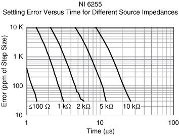
12 Technical Sales Canada (866) Requirements and Compatibility Ordering Information Detailed Specifications Pinouts/Front Panel Connections With recent bandwidth improvements and new innovations from National Instruments, USB has evolved into a core bus of choice for measurement and automation applications. NI M Series high-speed devices for USB deliver high-performance data acquisition in an easy-to-use and portable form factor through USB ports on laptop computers and other portable computing platforms. NI created NI signal streaming, an innovative patent-pending technology that enables sustained bidirectional high-speed data streams on USB. The new technology, combined with advanced external synchronization and isolation, helps engineers and scientists achieve high-performance applications on USB. M Series high-speed multifunction data acquisition (DAQ) modules for USB are optimized for superior accuracy at fast sampling rates. They provide an onboard NI-PGIA 2 amplifier designed for fast settling times at high scanning rates, ensuring 16-bit accuracy even when measuring all available channels at maximum speed. All high-speed devices have a minimum of 16 analog inputs, 24 digital I/O lines, seven programmable input ranges, analog and digital triggering, and two counter/timers. USB M Series devices are ideal for test, control, and design applications including portable data logging, field monitoring, embedded OEM, in-vehicle data acquisition, and academic. High-speed NI USB-625x M Series devices have an extended two-year calibration interval.
13 Unlike typical multifunction USB data acquisition devices, NI USB M Series DAQ devices incorporate NI signal streaming, a patent-pending technology that combines three innovative hardware- and software-level design elements to enable sustained high-speed and bidirectional data streams over USB. NI signal streaming, along with the error correction, noise rejection, power management, and power distribution inherent in the USB protocol, yields a robust, secure, and reliable bus. Without NI signal streaming, a multifunction data acquisition device could sustain only a single high-speed data stream, effectively making it a single-function device. For more information, visit ni.com/usb. For test, you can use the M Series high-speed analog inputs and 10 MHz digital lines with NI signal conditioning for applications including test, component characterization, and sensor measurement. High-speed USB-625x M Series devices are compatible with the NI SCC signal conditioning platform, providing amplification filtering and power for virtually every type of sensor. This platform is also compliant with IEEE smart transducer electronic data sheet (TEDS) sensors, which offer digital storage for sensor data sheet information. USB M Series multifunction DAQ devices also complement existing test systems that need additional measurement channels. For higher-channel-count signal conditioning on USB, consider the NI CompactDAQ or NI SCXI platform. USB M Series digital lines can drive 24 ma for relay and actuator control. By clocking the digital lines as fast as 10 MHz (with onboard regeneration), you can use these lines for pulse-width modulation (PWM) to control valves, motors, fans, lamps, and pumps. With four waveform analog outputs, two 80 MHz counter/timers, and four high-speed data streams on USB, M Series devices can execute multiple control loops simultaneously. High-speed USB-625x M Series devices also offer direct support for encoder measurements, protected digital lines, and digital debounce filters. With up to 80 analog inputs, 32 clocked digital lines, and four analog outputs, you can execute multiple control loops with a single device. You can also create a complete custom motion controller by combining USB M Series devices with the NI SoftMotion Development Module. For design applications, you can use a wide range of I/O from 80 analog inputs to 48 digital lines to measure and verify prototype designs. USB M Series devices and NI LabVIEW SignalExpress interactive measurement software deliver benchtop measurements to the PC. With LabVIEW SignalExpress, you can quickly create design verification tests. The fast acquisition and generation rates of high-performance USB M Series high-speed devices along with LabVIEW SignalExpress provide fast design analysis. You can convert your tested and verified LabVIEW SignalExpress projects to LabVIEW applications for immediate M Series DAQ use, and bridge the gap between test, control, and design applications. Shorten your time to market by integrating National Instruments OEM products in your design. Board-only versions of USB M Series DAQ devices are available for OEM applications, with competitive quantity pricing and software customization. The NI OEM Elite Program offers free 30-day trial kits for qualified customers. Visit ni.com/oem for more information. National Instruments measurement services software, built around NI-DAQmx driver software, includes intuitive application programming interfaces, configuration tools, I/O assistants, and other tools designed to reduce system setup, configuration, and development time. National Instruments recommends using the latest version of NI-DAQmx driver software for application development in NI LabVIEW, LabVIEW SignalExpress, LabWindows /CVI, and Measurement Studio. To obtain the latest version of NI-DAQmx, visit ni.com/support/daq/versions. NI measurement services software speeds up your development with features including: M Series devices are compatible with the following versions (or later) of NI application software LabVIEW, LabWindows/CVI, or Measurement Studio versions 7.x or LabVIEW SignalExpress 2.x. Signal conditioning is required for sensor measurements or voltage inputs greater than 10 V. NI SCC products, which are designed to increase the performance and reliability of your data acquisition system, are up to 10 times more accurate than using terminal blocks alone. For more information, visit ni.com/sigcon. For a complete list of accessories, visit the product page on ni.com.
14


15 NI measurement hardware is calibrated to ensure measurement accuracy and verify that the device meets its published specifications. To ensure the ongoing accuracy of your measurement hardware, NI offers basic or detailed recalibration service that provides ongoing ISO 9001 audit compliance and confidence in your measurements. To learn more about NI calibration services or to locate a qualified service center near you, contact your local sales office or visit ni.com/calibration. Get answers to your technical questions using the following National Instruments resources. Support - Visit ni.com/support to access the NI KnowledgeBase, example programs, and tutorials or to contact our applications engineers who are located in NI sales offices around the world and speak the local language. Discussion Forums - Visit forums.ni.com for a diverse set of discussion boards on topics you care about. Online Community - Visit community.ni.com to find, contribute, or collaborate on customer-contributed technical content with users like you.
16 While you may never need your hardware repaired, NI understands that unexpected events may lead to necessary repairs. NI offers repair services performed by highly trained technicians who quickly return your device with the guarantee that it will perform to factory specifications. For more information, visit ni.com/repair. The NI training and certification program delivers the fastest, most certain route to increased proficiency and productivity using NI software and hardware. Training builds the skills to more efficiently develop robust, maintainable applications, while certification validates your knowledge and ability. Classroom training in cities worldwide - the most comprehensive hands-on training taught by engineers. On-site training at your facility - an excellent option to train multiple employees at the same time. Online instructor-led training - lower-cost, remote training if classroom or on-site courses are not possible. Course kits - lowest-cost, self-paced training that you can use as reference guides. Training memberships and training credits - to buy now and schedule training later. Visit ni.com/training for more information. NI offers options for extending the standard product warranty to meet the life-cycle requirements of your project. In addition, because NI understands that your requirements may change, the extended warranty is flexible in length and easily renewed. For more information, visit ni.com/warranty. NI offers design-in consulting and product integration assistance if you need NI products for OEM applications. For information about special pricing and services for OEM customers, visit ni.com/oem.
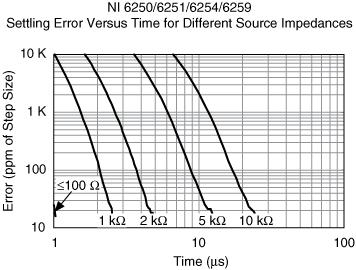
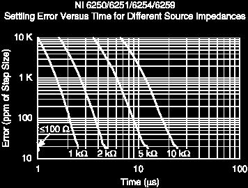
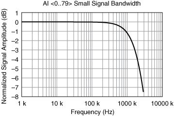
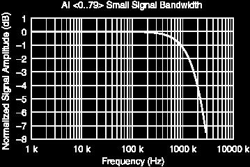
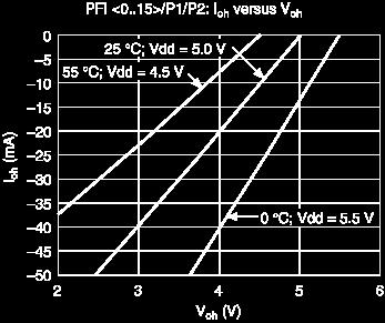
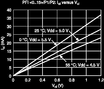
17 Specifications listed below are typical at 25 C unless otherwise noted. Refer to the M Series User Manual for more information about NI 625x devices.
18
19
20
21
22
23
24
25
26
27
28
29
30
31
32
33
34
DT9834 Series High-Performance Multifunction USB Data Acquisition Modules
 DT9834 Series High-Performance Multifunction USB Data Acquisition Modules DT9834 Series High Performance, Multifunction USB DAQ Key Features: Simultaneous subsystem operation on up to 32 analog input channels,
Sound and Vibration Data Acquisition
 NI 9233, NI 9234 NEW! 24-bit resolution 102 db dynamic range 4 simultaneous analog inputs ±5 V input range Antialiasing filters TEDS read/write Recommended Software LabVIEW Sound and Vibration Toolkit
ME EN 363 ELEMENTARY INSTRUMENTATION Lab: Basic Lab Instruments and Data Acquisition
 ME EN 363 ELEMENTARY INSTRUMENTATION Lab: Basic Lab Instruments and Data Acquisition INTRODUCTION Many sensors produce continuous voltage signals. In this lab, you will learn about some common methods
NI-DAQmx Device Considerations
 NI-DAQmx Device Considerations January 2008, 370738M-01 This help file contains information specific to analog output (AO) Series devices, C Series, B Series, E Series devices, digital I/O (DIO) devices,
Digital Input Modules for Compact FieldPoint
 Digital Modules for Compact FieldPoint NI cfp-di-300, NI cfp-di-301, NI cfp-di-304, NI 8-,16-, or 32-channel inputs 24 VDC inputs 4 to 250 VDC inputs 15 to 250 VAC inputs (50/60 Hz AC) 3 to 250 VAC inputs
Data Acquisition Using LabVIEW
 Experiment-0 Data Acquisition Using LabVIEW Introduction The objectives of this experiment are to become acquainted with using computer-conrolled instrumentation for data acquisition. LabVIEW, a program
Sound and Vibration Data Acquisition
 NI PXI-449x, NI PXIe-449x NEW! 16 simultaneous analog inputs 24-bit resolution 204.8 ks/s maximum sampling rate 114 db dynamic range +10, +20, and +30 db gains ±0.316, 1, 3.16, and 10 V input ranges Antialiasing
Thermocouple and RTD Modules for Compact FieldPoint
 Thermocouple and Modules for Compact FieldPoint NI cfp-tc-120, NI cfp-tc-125, NI cfp--122, NI cfp--124 8 temperature inputs Thermocouple or millivolt 2-, 3-, or 4-wire Built-in signal conditioning between
NI-DAQmx Key Concepts
 NI-DAQmx Key Concepts January 2008, 371407F-01 NI-DAQmx Key Concepts covers important concepts in NI-DAQmx such as channels and tasks. The ways that NI-DAQmx handles timing, triggering, buffering, and
Major Differences Between the DT9847 Series Modules
 DT9847 Series Dynamic Signal Analyzer for USB With Low THD and Wide Dynamic Range The DT9847 Series are high-accuracy, dynamic signal acquisition modules designed for sound and vibration applications.
Fig. 1. The Front Panel (Graphical User Interface)
") ME 4710 Motion and Control Data Acquisition Software for Step Excitation Introduction o These notes describe LabVIEW software that can be used for data acquisition. The overall software characteristics
ME 4710 Motion and Control Data Acquisition Software for Step Excitation Introduction o These notes describe LabVIEW software that can be used for data acquisition. The overall software characteristics
BNC-2120 INSTALLATION GUIDE. Connector Accessory for Multifunction DAQ Devices
 INSTALLATION GUIDE BNC-2120 Connector Accessory for Multifunction DAQ Devices This installation guide describes how to install, configure, and use your BNC-2120 accessory. If you have not already installed
2 MHz Lock-In Amplifier
 2 MHz Lock-In Amplifier SR865 2 MHz dual phase lock-in amplifier SR865 2 MHz Lock-In Amplifier 1 mhz to 2 MHz frequency range Dual reference mode Low-noise current and voltage inputs Touchscreen data display
Amplification. Most common signal conditioning
 1. Labview basics virtual instruments, data flow, palettes 2. Structures for, while, case,... editing techniques 3. Controls&Indicators arrays, clusters, charts, graphs 4. Additional lecture State machines,
Artisan Technology Group is your source for quality new and certified-used/pre-owned equipment
 Artisan Technology Group is your source for quality new and certified-used/pre-owned equipment FAST SHIPPING AND DELIVERY TENS OF THOUSANDS OF IN-STOCK ITEMS EQUIPMENT DEMOS HUNDREDS OF MANUFACTURERS SUPPORTED
Lab experience 1: Introduction to LabView
 Lab experience 1: Introduction to LabView LabView is software for the real-time acquisition, processing and visualization of measured data. A LabView program is called a Virtual Instrument (VI) because
Getting Started with the LabVIEW Sound and Vibration Toolkit
 1 Getting Started with the LabVIEW Sound and Vibration Toolkit This tutorial is designed to introduce you to some of the sound and vibration analysis capabilities in the industry-leading software tool
AI-1616L-LPE. Features. High-precision Analog input board (Low Profile size) for PCI Express AI-1616L-LPE 1. Ver.1.02 Ver.1.01
 for PCI Express AI-1616L-LPE 1. Ver.1.02 Ver.1.01") High-precision Analog input board (Low Profile size) for PCI Express AI-1616L-LPE This product is a multi-function, PCI Express bus-compliant interface board that incorporates high-precision 16-bit analog
High-precision Analog input board (Low Profile size) for PCI Express AI-1616L-LPE This product is a multi-function, PCI Express bus-compliant interface board that incorporates high-precision 16-bit analog
DT9857E. Key Features: Dynamic Signal Analyzer for Sound and Vibration Analysis Expandable to 64 Channels
 DT9857E Dynamic Signal Analyzer for Sound and Vibration Analysis Expandable to 64 Channels The DT9857E is a high accuracy dynamic signal acquisition module for noise, vibration, and acoustic measurements
Sample. Data Acquisition and Signal Conditioning. Course Manual. Course Software Version 2011 February 2012 Edition Part Number P-01
 Data Acquisition and Signal Conditioning Course Manual Course Software Version 2011 February 2012 Edition Part Number 320733P-01 Data Acquisition and Signal Conditioning Copyright 1995 2012 National Instruments
Introduction To LabVIEW and the DSP Board
 EE-289, DIGITAL SIGNAL PROCESSING LAB November 2005 Introduction To LabVIEW and the DSP Board 1 Overview The purpose of this lab is to familiarize you with the DSP development system by looking at sampling,
NanoGiant Oscilloscope/Function-Generator Program. Getting Started
 Getting Started Page 1 of 17 NanoGiant Oscilloscope/Function-Generator Program Getting Started This NanoGiant Oscilloscope program gives you a small impression of the capabilities of the NanoGiant multi-purpose
USB Smart Power Sensor
 50Ω -30 dbm to +20 dbm, 1 MHz to 8000 MHz The Big Deal Fast measurement speed, 10 msec USB HID device compatible with 32/64 Bit operating systems Includes Measurement Application GUI (Graphical User Interface)
100 MHz, 100 MS/s, 14-Bit Digitizer
 NI 5122 2 channels simultaneously sampled at 14-bit resolution 100 MS/s real-time and 2.0 GS/s random interleaved sampling 100 MHz bandwidth 50 Ω or 1 MΩ input impedance, software-selectable 200 mv to
Using SignalTap II in the Quartus II Software
 White Paper Using SignalTap II in the Quartus II Software Introduction The SignalTap II embedded logic analyzer, available exclusively in the Altera Quartus II software version 2.1, helps reduce verification
SignalTap Plus System Analyzer
 SignalTap Plus System Analyzer June 2000, ver. 1 Data Sheet Features Simultaneous internal programmable logic device (PLD) and external (board-level) logic analysis 32-channel external logic analyzer 166
PicoScope 6407 Digitizer
 YE AR PicoScope 6407 Digitizer HIGH PERFORMANCE USB DIGITIZER Programmable and Powerful 1 GHz bandwidth 1 GS buffer size 5 GS/s real-time sampling Advanced digital triggers Built-in function generator
PicoScope 6407 Digitizer
 YE AR HIGH PERFORMANCE USB DIGITIZER Programmable and Powerful 1 GHz bandwidth 1 GS buffer size 5 GS/s real-time sampling Advanced digital triggers Built-in function generator USB-connected Signals Analysis
GFT Channel Digital Delay Generator
 Features 20 independent delay Channels 100 ps resolution 25 ps rms jitter 10 second range Output pulse up to 6 V/50 Ω Independent trigger for every channel Fours Triggers Three are repetitive from three
DT9837 Series. High Performance, USB Powered Modules for Sound & Vibration Analysis. Key Features:
 DT9837 Series High Performance, Powered Modules for Sound & Vibration Analysis The DT9837 Series high accuracy dynamic signal acquisition modules are ideal for portable noise, vibration, and acoustic measurements.
Transmitter Interface Program
 Transmitter Interface Program Operational Manual Version 3.0.4 1 Overview The transmitter interface software allows you to adjust configuration settings of your Max solid state transmitters. The following
AI-1664LAX-USB. Features. 100KSPS 16-bit Analog Input Unit for USB AI-1664LAX-USB 1. Ver.1.01
 100KSPS 16-bit Analog Unit for USB AI-1664LAX-USB * Specifications, color and design of the products are subject to change without notice. This product is a USB2.0-compliant analog input unit that extends
Operating Instructions
 Operating Instructions HAEFELY TEST AG KIT Measurement Software Version 1.0 KIT / En Date Version Responsable Changes / Reasons February 2015 1.0 Initial version WARNING Introduction i Before operating
Design and Realization of the Guitar Tuner Using MyRIO
 Journal of Automation and Control, 2017, Vol. 5, No. 2, 41-45 Available online at http://pubs.sciepub.com/automation/5/2/2 Science and Education Publishing DOI:10.12691/automation-5-2-2 Design and Realization
VIRTUAL INSTRUMENTATION
 VIRTUAL INSTRUMENTATION Virtual instrument an equimplent that allows accomplishment of measurements using the computer. It looks like a real instrument, but its operation and functionality is essentially
DT3162. Ideal Applications Machine Vision Medical Imaging/Diagnostics Scientific Imaging
 Compatible Windows Software GLOBAL LAB Image/2 DT Vision Foundry DT3162 Variable-Scan Monochrome Frame Grabber for the PCI Bus Key Features High-speed acquisition up to 40 MHz pixel acquire rate allows
Oscilloscopes, logic analyzers ScopeLogicDAQ
 Oscilloscopes, logic analyzers ScopeLogicDAQ ScopeLogicDAQ 2.0 is a comprehensive measurement system used for data acquisition. The device includes a twochannel digital oscilloscope and a logic analyser
Features of the 745T-20C: Applications of the 745T-20C: Model 745T-20C 20 Channel Digital Delay Generator
 20 Channel Digital Delay Generator Features of the 745T-20C: 20 Independent delay channels - 100 ps resolution - 25 ps rms jitter - 10 second range Output pulse up to 6 V/50 Ω Independent trigger for every
Welch Allyn CardioPerfect Workstation Tango+ Interface Notes
 Welch Allyn CardioPerfect Workstation Tango+ Interface Notes To setup Tango+ with the CardioPerfect stress system, simply follow the directions below. 1. Verify Correct RS-232 and ECG Trigger Cables RS-232
QUICK START GUIDE FOR DEMONSTRATION CIRCUIT /12/14 BIT 10 TO 65 MSPS DUAL ADC
 LTC2286, LTC2287, LTC2288, LTC2290, LTC2291, LTC2292, LTC2293, LTC2294, LTC2295, LTC2296, LTC2297, LTC2298 or LTC2299 DESCRIPTION Demonstration circuit 816 supports a family of s. Each assembly features
Artisan Technology Group is your source for quality new and certified-used/pre-owned equipment
 Artisan Technology Group is your source for quality new and certified-used/pre-owned equipment FAST SHIPPING AND DELIVERY TENS OF THOUSANDS OF IN-STOCK ITEMS EQUIPMENT DEMOS HUNDREDS OF MANUFACTURERS SUPPORTED
MSO-28 Oscilloscope, Logic Analyzer, Spectrum Analyzer
 Link Instruments Innovative Test & Measurement solutions since 1986 Store Support Oscilloscopes Logic Analyzers Pattern Generators Accessories MSO-28 Oscilloscope, Logic Analyzer, Spectrum Analyzer $ The
Ensemble QLAB. Stand-Alone, 1-4 Axes Piezo Motion Controller. Control 1 to 4 axes of piezo nanopositioning stages in open- or closed-loop operation
 Ensemble QLAB Motion Controllers Ensemble QLAB Stand-Alone, 1-4 Axes Piezo Motion Controller Control 1 to 4 axes of piezo nanopositioning stages in open- or closed-loop operation Configurable open-loop
Basic LabVIEW Programming Amit J Nimunkar, Sara Karle, Michele Lorenz, Emily Maslonkowski
 Introduction This lab familiarizes you with the software package LabVIEW from National Instruments for data acquisition and virtual instrumentation. The lab also introduces you to resistors, capacitors,
AD16-64(LPCI)LA. Non-isolated high precision analog input board for Low Profile PCI AD16-64(LPCI)LA 1. Ver.1.01
LA. Non-isolated high precision analog input board for Low Profile PCI AD16-64(LPCI)LA 1. Ver.1.01") Non-isolated high precision analog board for Low Profile PCI AD16-64(LPCI)LA * Specifications, color and design of the products are subject to change without notice. This product is a PCI bus compatible
Non-isolated high precision analog board for Low Profile PCI AD16-64(LPCI)LA * Specifications, color and design of the products are subject to change without notice. This product is a PCI bus compatible
Product Information. EIB 700 Series External Interface Box
 Product Information EIB 700 Series External Interface Box June 2013 EIB 700 Series The EIB 700 units are external interface boxes for precise position measurement. They are ideal for inspection stations
Implementing a Rudimentary Oscilloscope
 EE-3306 HC6811 Lab #4 Implementing a Rudimentary Oscilloscope Objectives The purpose of this lab is to become familiar with the 68HC11 on chip Analog-to-Digital converter. This lab builds on the knowledge
Troubleshooting Your Design with Tektronix MSO and DPO Series Oscilloscopes
 Troubleshooting Your Design with Tektronix MSO and DPO Series Oscilloscopes Our thanks to Tektronix for allowing us to reprint the following article. Today s engineers and technicians face increasingly
FCPM-6000RC. Mini-Circuits P.O. Box , Brooklyn, NY (718)
") USB / Ethernet Integrated Frequency Counter & Power Meter 50Ω -30 dbm to +20 dbm, 1 MHz to 6000 MHz The Big Deal Automatically synchronized power & frequency measurements USB and Ethernet control Includes
USB / Ethernet Integrated Frequency Counter & Power Meter 50Ω -30 dbm to +20 dbm, 1 MHz to 6000 MHz The Big Deal Automatically synchronized power & frequency measurements USB and Ethernet control Includes
SignalTap Analysis in the Quartus II Software Version 2.0
 SignalTap Analysis in the Quartus II Software Version 2.0 September 2002, ver. 2.1 Application Note 175 Introduction As design complexity for programmable logic devices (PLDs) increases, traditional methods
USB Smart Power Sensor
 75Ω -30 dbm to +20 dbm, 100 khz to 2500 MHz The Big Deal 75Ω Impedance Low cost USB HID device compatible with 32/64 Bit operating systems Includes Measurement Application GUI (Graphical User Interface)
QUICK START GUIDE FOR DEMONSTRATION CIRCUIT /12/14 BIT 10 TO 105 MSPS ADC
 LTC2280, LTC2282, LTC2284, LTC2286, LTC2287, LTC2288 LTC2289, LTC2290, LTC2291, LTC2292, LTC2293, LTC2294, LTC2295, LTC2296, LTC2297, LTC2298 or LTC2299 DESCRIPTION Demonstration circuit 851 supports a
The Design of Teaching Experiment System Based on Virtual Instrument Technology. Dayong Huo
 3rd International Conference on Management, Education, Information and Control (MEICI 2015) The Design of Teaching Experiment System Based on Virtual Instrument Technology Dayong Huo Department of Physics,
16-BIT LOAD CELL/DUAL STATUS INPUT
 16-BIT LOAD CELL/DUAL STATUS INPUT On-board Excitation. +5VDC, (120mA). State-of-the-art Electromagnetic Noise Suppression Circuitry. Ensures signal integrity even in harsh EMC environments. Optional Excitation
4 MHz Lock-In Amplifier
 4 MHz Lock-In Amplifier SR865A 4 MHz dual phase lock-in amplifier SR865A 4 MHz Lock-In Amplifier 1 mhz to 4 MHz frequency range Low-noise current and voltage inputs Touchscreen data display - large numeric
Solutions to Embedded System Design Challenges Part II
 Solutions to Embedded System Design Challenges Part II Time-Saving Tips to Improve Productivity In Embedded System Design, Validation and Debug Hi, my name is Mike Juliana. Welcome to today s elearning.
EMS DATA ACQUISITION AND MANAGEMENT (LVDAM-EMS) MODEL 9062-C
 MODEL 9062-C") A Electric Power / Controls 2 kw EMS DATA ACQUISITION AND MANAGEMENT (LVDAM-EMS) MODEL 9062-C GENERAL DESCRIPTION The Lab-Volt Data Acquisition and Management for Electromechanical Systems (LVDAM-EMS),
A Electric Power / Controls 2 kw EMS DATA ACQUISITION AND MANAGEMENT (LVDAM-EMS) MODEL 9062-C GENERAL DESCRIPTION The Lab-Volt Data Acquisition and Management for Electromechanical Systems (LVDAM-EMS),
ENGR 1000, Introduction to Engineering Design
 ENGR 1000, Introduction to Engineering Design Unit 2: Data Acquisition and Control Technology Lesson 2.4: Programming Digital Ports Hardware: 12 VDC power supply Several lengths of wire NI-USB 6008 Device
SC26 Magnetic Field Cancelling System
 SPICER CONSULTING SYSTEM SC26 SC26 Magnetic Field Cancelling System Makes the ambient magnetic field OK for electron beam tools in 300 mm wafer fabs Real time, wideband cancelling from DC to > 9 khz fields
SNG-2150C User s Guide
 SNG-2150C User s Guide Avcom of Virginia SNG-2150C User s Guide 7730 Whitepine Road Revision 001 Richmond, VA 23237 USA GENERAL SAFETY If one or more components of your earth station are connected to 120
Choosing an Oscilloscope
 Choosing an Oscilloscope By Alan Lowne CEO Saelig Company (www.saelig.com) Post comments on this article at www.nutsvolts.com/ magazine/article/october2016_choosing-oscilloscopes. All sorts of questions
LabView Exercises: Part II
 Physics 3100 Electronics, Fall 2008, Digital Circuits 1 LabView Exercises: Part II The working VIs should be handed in to the TA at the end of the lab. Using LabView for Calculations and Simulations LabView
ECE 4220 Real Time Embedded Systems Final Project Spectrum Analyzer
 ECE 4220 Real Time Embedded Systems Final Project Spectrum Analyzer by: Matt Mazzola 12222670 Abstract The design of a spectrum analyzer on an embedded device is presented. The device achieves minimum
ATS MS/s 8-Bit PCI Digitizer
 2 channels sampled at 8-bit resolution 50 MS/s simultaneous real-time sampling rate on each input ±20mV to ±20V input range 256 Kilo samples of on-board acquisition memory per channel AlazarDSO Oscilloscope
PRELIMINARY INFORMATION. Professional Signal Generation and Monitoring Options for RIFEforLIFE Research Equipment
 Integrated Component Options Professional Signal Generation and Monitoring Options for RIFEforLIFE Research Equipment PRELIMINARY INFORMATION SquareGENpro is the latest and most versatile of the frequency
SC24 Magnetic Field Cancelling System
 SPICER CONSULTING SYSTEM SC24 SC24 Magnetic Field Cancelling System Makes the ambient magnetic field OK for the electron microscope Adapts to field changes within 100 µs Touch screen intelligent user interface
Boonton 4540 Remote Operation Modes
 Application Note Boonton 4540 Remote Operation Modes Mazumder Alam Product Marketing Manager, Boonton Electronics Abstract Boonton 4540 series power meters are among the leading edge instruments for most
DT3130 Series for Machine Vision
 Compatible Windows Software DT Vision Foundry GLOBAL LAB /2 DT3130 Series for Machine Vision Simultaneous Frame Grabber Boards for the Key Features Contains the functionality of up to three frame grabbers
Logic Analysis Basics
 Logic Analysis Basics September 27, 2006 presented by: Alex Dickson Copyright 2003 Agilent Technologies, Inc. Introduction If you have ever asked yourself these questions: What is a logic analyzer? What
AI-1204Z-PCI. Features. 10MSPS, 12-bit Analog Input Board for PCI AI-1204Z-PCI 1. Ver.1.04
 10MSPS, 12-bit Analog Board for PCI AI-1204Z-PCI * Specifications, color and design of the products are subject to change without notice. This product is a PCI bus-compliant interface board that expands
Logic Analysis Basics
 Logic Analysis Basics September 27, 2006 presented by: Alex Dickson Copyright 2003 Agilent Technologies, Inc. Introduction If you have ever asked yourself these questions: What is a logic analyzer? What
PicoScope PC Oscilloscopes. User's Guide. ps2203.en r4 Copyright Pico Technology Limited. All rights reserved.
 PicoScope 2203 PC Oscilloscopes User's Guide PicoScope 2203 User's Guide I Contents 1 Welcome...1 2 Introduction...2 1 Using this guide 2 Safety symbols 3 Safety warning 4 FCC notice 5 CE notice...2...2...3...4...4...5
Agilent N7744A 4-Channel Optical Multiport Power Meter N7745A 8-Channel Optical Multiport Power Meter. Fully compliant to LXI Class C specification
 Agilent N7744A 4-Channel Optical Multiport Power Meter N7745A 8-Channel Optical Multiport Power Meter Fully compliant to LXI Class C specification General Information Up to 8 power meter channels in a
SC24 Magnetic Field Cancelling System
 SPICER CONSULTING SYSTEM SC24 SC24 Magnetic Field Cancelling System Makes the ambient magnetic field OK for the electron microscope Adapts to field changes within 100 µs Touch screen intelligent user interface
Triple RTD. On-board Digital Signal Processor. Linearization RTDs 20 Hz averaged outputs 16-bit precision comparator function.
 Triple RTD SMART INPUT MODULE State-of-the-art Electromagnetic Noise Suppression Circuitry. Ensures signal integrity even in harsh EMC environments. On-board Digital Signal Processor. Linearization RTDs
Recording of Coincidence Signals in a Software Medium
 Science Journal of Circuits, Systems and Signal Processing 2018; 7(1): 28-33 http://www.sciencepublishinggroup.com/j/cssp doi: 10.11648/j.cssp.20180701.14 ISSN: 2326-9065 (Print); ISSN: 2326-9073 (Online)
MTL Software. Overview
 MTL Software Overview MTL Windows Control software requires a 2350 controller and together - offer a highly integrated solution to the needs of mechanical tensile, compression and fatigue testing. MTL
PB-507. Advanced Analog & Digital Electronic Design Workstation Instruction Manual. Revision: 2/2014
 PB-507 Advanced Analog & Digital Electronic Design Workstation Instruction Manual Revision: 2/2014 Test Equipment Depot - 800.517.8431-99 Washington Street Melrose, MA 02176 TestEquipmentDepot.com 1 1
OPTIMUM Power Technology: Low Cost Combustion Analysis for University Engine Design Programs Using ICEview and NI Compact DAQ Chassis
 OPTIMUM Power Technology: Low Cost Combustion Analysis for University Engine Design Programs Using ICEview and NI Compact DAQ Chassis World Headquarters (USA): European Sales Office: Japanese Office: 3117
Mortara X-Scribe Tango+ Interface Notes
 Mortara X-Scribe Tango+ Interface Notes To setup Tango+ with the X-Scribe stress system, simply follow the directions below. 1. Verify Correct RS-232 and ECG Trigger Cables RS-232 Cable used to communicate
Automated Limit Testing
 Automated Limit Testing Limit Testing with Tektronix DPO4000 and MSO4000 Series Oscilloscopes and National Instruments LabVIEW SignalExpress TE for Windows TM Introduction Automated limit testing allows
MIE 402: WORKSHOP ON DATA ACQUISITION AND SIGNAL PROCESSING Spring 2003
 MIE 402: WORKSHOP ON DATA ACQUISITION AND SIGNAL PROCESSING Spring 2003 OBJECTIVE To become familiar with state-of-the-art digital data acquisition hardware and software. To explore common data acquisition
GALILEO Timing Receiver
 GALILEO Timing Receiver The Space Technology GALILEO Timing Receiver is a triple carrier single channel high tracking performances Navigation receiver, specialized for Time and Frequency transfer application.
Artisan Technology Group is your source for quality new and certified-used/pre-owned equipment
 Artisan Technology Group is your source for quality new and certified-used/pre-owned equipment FAST SHIPPING AND DELIVERY TENS OF THOUSANDS OF IN-STOCK ITEMS EQUIPMENT DEMOS HUNDREDS OF MANUFACTURERS SUPPORTED
Experiment 13 Sampling and reconstruction
 Experiment 13 Sampling and reconstruction Preliminary discussion So far, the experiments in this manual have concentrated on communications systems that transmit analog signals. However, digital transmission
NI SC Express. NI PXIe-4300 User Manual. NI PXIe-4300 User Manual. April A-01
 NI SC Express NI PXIe-4300 User Manual NI PXIe-4300 User Manual April 2010 373024A-01 Support Worldwide Technical Support and Product Information ni.com National Instruments Corporate Headquarters 11500
DPD80 Visible Datasheet
 Data Sheet v1.3 Datasheet Resolved Inc. www.resolvedinstruments.com info@resolvedinstruments.com 217 Resolved Inc. All rights reserved. General Description The DPD8 is a low noise digital photodetector
Data Pattern Generator DG2020A Data Sheet
 Data Pattern Generator DG2020A Data Sheet DG2000 Series Features & Benefits Data Rate to 200 Mb/s Data Pattern Depth 64 K/channel Speeds Characterization Multiple Output Channels Increases Flexibility
Lab 2: A/D, D/A, and Sampling Theorem
 Lab 2: A/D, D/A, and Sampling Theorem Introduction The purpose of this lab is to explore the principles of analog-to-digital conversion, digital-to-analog conversion, and the sampling theorem. It will
Application Note #63 Field Analyzers in EMC Radiated Immunity Testing
 Application Note #63 Field Analyzers in EMC Radiated Immunity Testing By Jason Galluppi, Supervisor Systems Control Software In radiated immunity testing, it is common practice to utilize a radio frequency
Synthesized Clock Generator
 Synthesized Clock Generator CG635 DC to 2.05 GHz low-jitter clock generator Clocks from DC to 2.05 GHz Random jitter
BNC-2110 DESKTOP AND DIN RAIL-MOUNTABLE BNC ADAPTER
 INSTALLATION GUIDE BNC-2110 DESKTOP AND DIN RAIL-MOUNTABLE BNC ADAPTER Introduction This installation guide describes how to install and configure your BNC-2110 accessory with an E Series or waveform generation
Analyzing and Saving a Signal
 Analyzing and Saving a Signal Approximate Time You can complete this exercise in approximately 45 minutes. Background LabVIEW includes a set of Express VIs that help you analyze signals. This chapter teaches
Topic: Instructional David G. Thomas December 23, 2015
 Procedure to Setup a 3ɸ Linear Motor This is a guide to configure a 3ɸ linear motor using either analog or digital encoder feedback with an Elmo Gold Line drive. Topic: Instructional David G. Thomas December
DPD80 Infrared Datasheet
 Data Sheet v1.4 DPD8 Infrared DPD8 Infrared Datasheet Resolved Inc. www.resolvedinstruments.com info@resolvedinstruments.com 217 Resolved Inc. All rights reserved. DPD8 Infrared General Description The
CHAPTER 3 ECG SIGNAL RECORDING USING LABVIEW
 103 CHAPTER 3 ECG SIGNAL RECORDING USING LABVIEW 3.1 INTRODUCTION The Work has been inspired by the need to find an efficient method for ECG signal recording and processing. ECG signals are non-stationary
Virtual instruments and introduction to LabView
 Introduction Virtual instruments and introduction to LabView (BME-MIT, updated: 26/08/2014 Tamás Krébesz krebesz@mit.bme.hu) The purpose of the measurement is to present and apply the concept of virtual
Using the BHM binaural head microphone
 11/17 Using the binaural head microphone Introduction 1 Recording with a binaural head microphone 2 Equalization of a recording 2 Individual equalization curves 5 Using the equalization curves 5 Post-processing
Telephony Training Systems
 Telephony Training Systems LabVolt Series Datasheet Festo Didactic en 120 V - 60 Hz 07/2018 Table of Contents General Description 2 Topic Coverage 6 Features & Benefits 6 List of Available Training Systems
Burlington County College INSTRUCTION GUIDE. for the. Hewlett Packard. FUNCTION GENERATOR Model #33120A. and. Tektronix
 v1.2 Burlington County College INSTRUCTION GUIDE for the Hewlett Packard FUNCTION GENERATOR Model #33120A and Tektronix OSCILLOSCOPE Model #MSO2004B Summer 2014 Pg. 2 Scope-Gen Handout_pgs1-8_v1.2_SU14.doc