Music-Visualization and Motion-Controlled LED Cube
|
|
|
- Adele Townsend
- 5 years ago
- Views:
Transcription
1 Music-Visualization and Motion-Controlled LED Cube 1 Introduction 1.1 Objective Team 34: Hieu Tri Huynh, Islam Kadri, Zihan Yan ECE 445 Project Proposal Spring 2018 TA: Zhen Qin Our project s main inspiration came from a video about an art piece called Kinetic Rain at Singapore s Changi Airport. The sculpture cycles over 16 pre-programmed shapes, through fluidlike movement. [1] The construction of the sculpture was made using over 1,200 bronze droplets, steel wires to hold the droplets, and cost several million dollars. [2][3] Although Kinetic Rain looks very visually pleasing, we wanted to implement something that not only had visually pleasing animation, but through real time sound input. The Kinetic Rain device's engineering seems very complex and cumbersome to fix if there were any issues to arise. Also, we wanted to implement this in a manner that would be very cost effective compared to Kinetic Rain. Our team decided we wanted to build a device that took advantage of LED technology s efficient and aesthetically pleasing properties. An LED grid allows us to display visually pleasing animations by turning off a set of LEDs and keeping others on to mimic the shape that we want. Although there are other LED displays that have music visualization capabilities, ours would not only use a sound's frequency, but its tempo, amplitude, and angle of arrival. Additionally, we d like to have the user be able to interact with the LED grid to affect the animations within device. By taking something that is traditionally 2-dimensional and implementing a 3-dimensional version, we can show off the benefits of user interaction as well as increase the entertainment factor of the device. We plan on doing this by making a Snake game that uses proximity sensors to control the snake s direction.
2 1.2 Background The Kinetic Rain sculpture's may be aesthetically pleasing, but that comes at a cost. The sculpture has a price tag of over $7 million and has expensive and unique parts that are hard to replace. [2] Our device would also be more cost efficient and be easy to fix if something were to go wrong with any of the pieces. Additionally, the sculpture took around 2 years to put together. [3] The Kinetic Rain was damaged on November 2 nd, 2013 by a woman who climbed and hung onto the bronze droplets. The repair took engineers several months and was costly. [4] With our device, we'd have a low cost and easy to repair LED grid that would use live sound input to affect the animations, so visitors may be exposed to new unique animations each time they visit. Our device would be more scalable because of its modularity and cost. The tax payer burden would also be less if a government municipality were to commission our device versus something like Kinetic Rain. Although there are devices that can display aesthetically pleasing animations, ours uses four sources of input to affect the animation. Our device will also have an interactive mode to allow users to affect animations. Even with the LED Cube ECE 445 project from the Fall 2013 semester, they their phone application to affect user input. We will expand on this in terms of number of input as well as improve the way a user interacts with the LEDs. 1.3 High-Level Requirements Capture the frequency, amplitude, angle of arrival, and tempo from incoming sound in an accurate manner and make sure each of the sources affect the LEDs appropriately. Proximity sensors must be able to pick up motions of user to affect the 6 different directions (Up, Down, Left, Right, Outward, Inward) that the snake can move. Make sure the LEDs colors and off/on states are correct with respect to the mode that the device is in.
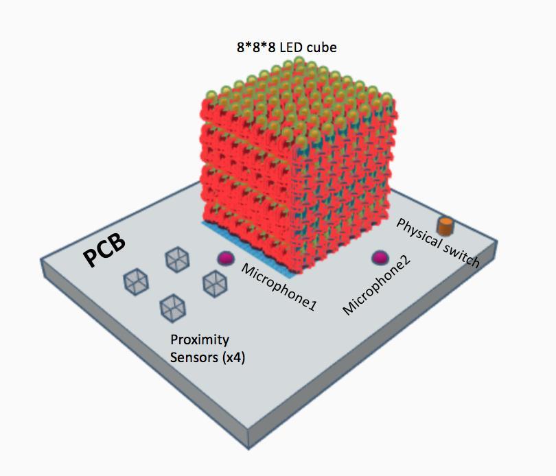
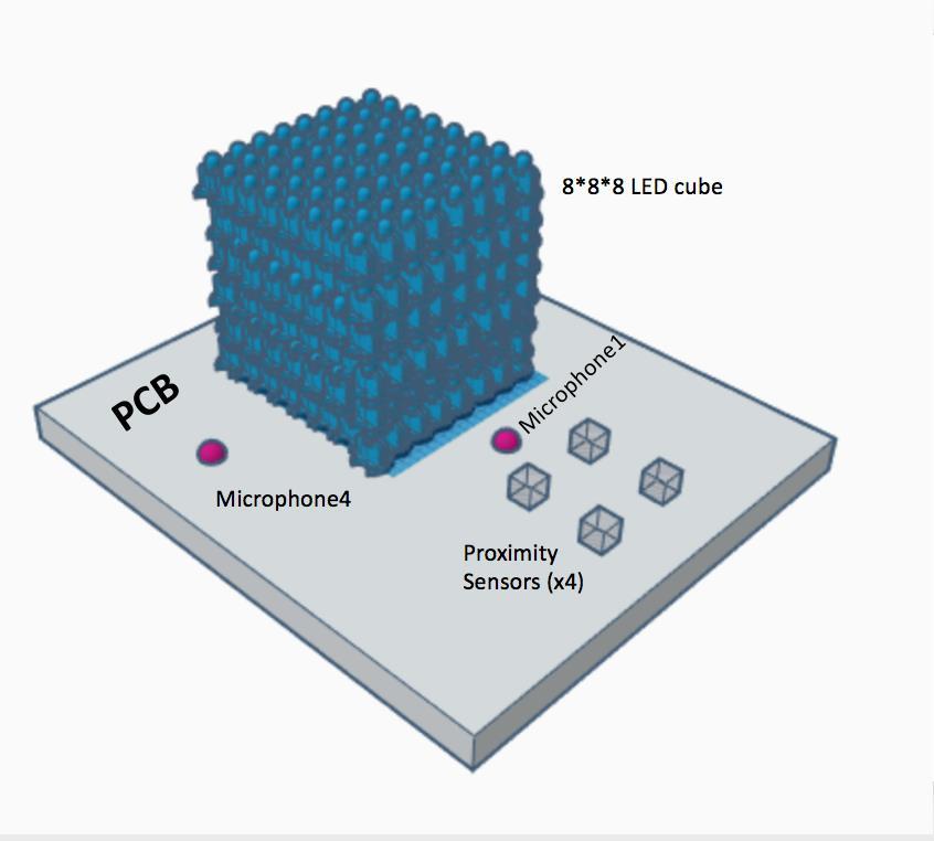
3 2 Design 2.1 Block Diagram & Physical Design Block Diagram Physical Design Figure 1 The LED module consists of 512, 5mm RGB LEDs, which are arranged into a 8x8x8 grid. We plan to arrange the LEDs such that the horizontal and vertical distances between any 2 LEDs is 1.25 inches. This will be placed on a flat rectangular surface approximately 24 x 18 inches square, that will have our sensors hooked up to. The cube will be placed in the upper middle part of the whole design with dimension 8.75inches x 8.75inches x8.75inches. 4 inches away from the three edges of the board where we are going to put the microphones at. The fourth edge is 2 inches away from the proximity sensor group, which also contains the fourth microphone within. Four proximity sensors are arranged two by two into a rectangular group with the distance 0.75 inches away from each other. The group dimension is 2 by 4 inches square. The diagram of

4 physical design is shown below.
5

6 2.2 Functional Overview Power Module This module is responsible for supplying power to the other components in our design. We estimate a voltage of 5VDC will be needed to power the LEDs, Microcontroller, the sensors, the microphones, and the analog to digital signal converter. These are estimates and may change depending on model of the parts specified above. The source of the power will be alternating around 120VAC and will need to be converted to 5VDC. Requirement: Must power all components of the device, as well as the LEDs, with 5VDC. Requirements 1. Power rating greater than 60 Watts to ensure that our device is well powered and safe to use. Verification 1. Use a multimeter to ensure the HC-SR04 is receiving the appropriate amount of voltage and current.
7 2.2.2 Microphone Module This module is used to collect the sound from the environment. This module contains 4 electret microphones and 1 digital microphone (ICS-5200). All microphones must have frequency response from 20Hz to 20 khz. For the digital microphone, it has more than 44 khz sampling rate satisfying Nyquist rate for 20kHz signal. The output of the digital microphone will be fed directly to the controller unit. We use this microphone to analyze the frequency and amplitude of the sound. The 4 electret microphones will be used to detect the direction of arrival of the sound. The output of 4 electret microphones will be amplified by 4 amplifiers before going to the controller unit. Since we use Arduino Zero, we can directly feed the analog signals to it. Requirements 1. All four electret and one MEMS microphone can accurately receive sound input. 2. Amplifier must properly amplify the signals so that the signal magnitude is in rage 0-5V before feeding it to the control unit Verification 1. Use an oscilloscope to measure the sound input from each microphone to ensure it is accurate enough. 2. Use an oscilloscope to measure the output of Amplifier Proximity Sensor Module The proximity sensor module is used to pick up how close the user's hand is in order to control the snake when the device is in gaming mode. This proximity sensor module contains 4 ultrasonic sensors arranged at certain positions. These sensors will detect if user's hand is above the sensors and generate analog outputs of 0-10VDC (depending on the model), which will be fed into the control unit. The control unit will then use the signal from the sensors to make decisions about where the snake should move.
8 Requirement: Each sensor must detect the hand positions from a range of 3 cm to 1m. Requirement: Each sensor must detect the position of hand when hand is moving fast. Requirements 1. Ensure minimum working DC voltage and current is 5V and 15mA respectively. Verification 1. Use a multimeter to ensure the HC-SR04 is receiving the appropriate amount of voltage and current. 2. Identify which four sensors are being used to detect the direction that one s hand is moving. 3. Ensure that sensors can pick up signals from a minimum of 2cm. 2. Take the time difference between sensors to determine which direction a hand is moving. For example, with two sensors next to each other, if one sensor (A) detects a hand over it and then the sensor (B) to its left detects the hand over it, we can calculate the time difference between A and B to determine the direction the user wants the snake to move. 3. Use the time range between sending the trigger signal and the echo signal received to calculate appropriate distance read from the sensors Control Unit The controller unit will take 4 analog signals from 4 amplifiers in the microphone modules, 1 digital signal from the digital microphone, and 4 digital signals from 4 Ultrasonic sensors in Proximity sensor module. Furthermore, there is a button to switch between 2 modes, Music and Gaming modes. This control unit will output 4 digitals signals to drive the LED module. For the control unit, we will use the Arduino Zero because of a few reasons. First of all, Arduino Zero is more powerful than older version, Arduino Uno. Next, it supports the I2C interface which allows us connect directly to the digital microphone. The control unit will perform tasks based on the mode of the device. When the device is in Gaming mode, the controller unit will use the 4 inputs from Proximity Sensor Module to run the algorithm of the
9 Snake Game described below. When the device is in Music mode, the control unit will calculate the FFT, amplitude of the sound based on the input from the digital microphone, and calculate the direction of arrival by comparing the input of the 4 electret microphones. Requirements 1. Supplies modules with the stabilized voltage that ranges from 3.3V to 5.5V to operate. Verification 1. Measure voltage and current using the appropriate device LED Module This module contains 8x8x8 a grid of 5mm RGB common cathode LEDs. Because we have 512 RGB LEDS each has 4 pins, we need to control 512 * 4 = 2048 pins. Instead of having 2048 outputs from the controller unit to control these LEDs, we will use 25 8-bit shift register to control these 512 LEDs. The controller unit will control the LED module by inputting 4 digital inputs: DATA, CLK, OE, and LATCH. To make it easier to understand how we connect the LEDs, let imagine that these 512 LEDs are placed in a 3D grid, each LED will have a tuple (x, y, z) represent its position; z represents the layer, x and y represent position in a 2d horizontal plane. We will connect all 64 cathode pins of 64 LEDs on the same level (LEDs that have the same z-value) together, then use an 8-bit shift register (SN54HC595) to control the status of these 8 layers. Then, for LEDs with same x-value and y-value we will connect their Red anodes together, Green anodes together, and Blue anodes together. Since, a horizontal plane has 64 LEDs, we will need 64 bits to control the 64 Red anodes, 64 bits to control the 64 Green anodes, and 64 bits to control the 64 Blue anodes. Therefore, we will need 64*3 = 192 bits to control the
10 RGB Anodes of LEDs. Therefore, we will need 192/8 = 24 8-bit shift registers. All the shift register will be connected in series as shown below so that the control unit can control the LEDs by shift out data into the series of shift registers. To control the LED, the controller unit will need to shift 200 bits into these 25 registers, then set the Latch pins of these registers so that the values is load into LEDs. These 200 bits can be indexed as follow: [0-7]: To control which level is ON [8-71]: To control Green Anodes [72-135]: to control Red Anodes [136, 199]: To control Blue Anodes To control the color of the LEDs, we will use the BAM (Bit Angle Modulation) method. We will use 4-bit BAM, which give us 16 Red levels, 16 Green levels, and 16 Blue levels. Therefore, we will have 16*16*16 = 4096 colors. Requirements 1. Make sure each LED works properly, as well as having combinations/columns of LEDs work together. 2. LEDs RGB functionality works in an appropriate manner. Verification 1. Test each LED before adding it to the grid, as well as testing each column of LEDs when put together in the grid. Lastly, test the entire grid of LEDs to make sure it lights up. 2. Test each RGB color by enabling it from the microcontroller.
11 2.2.7 Physical Button The physical button allows us to change between the two modes our project contains: music-visualization and motion-controlled 3D Snake. The button is directly powered by the power module and after being pushed, the signal will go to the control unit and the mode will be changed. The LEDs will receive the signal and change accordingly. Requirement: must be able to send the signal to the control unit and be able to change the operation mode. Requirements 1. Ensure that the LED device switches from Music Visualization to Snake mode. Verification 1. Connect the Pushbutton Switch to the microcontroller. With two states to choose from, we make sure that each button click responds correctly to the mode it is supposed to be in. 2.3 Software Flowchart
12 Figure for 3D Snake Game Flow Chart
13 2.4 Schematics Figure for Music Visualization LED Device Flow Chart
14 Figure for Ultrasonic Sensor Module Figure for Registers
15 Figure for LEDs 2.5 Risk Analysis The most difficult part of the project will be making sure all the LEDs in our grid are properly connected and functioning. Because we have so many LEDs, making sure all of them work immaculately is pivotal to our project succeeding. Some LEDs may also be faulty so replacing them could be very cumbersome. Additionally, making sure that the proximity sensors pick up the right signals and that we can translate them to directions for the Snake game will be somewhat difficult due to the nature of a sensor potentially not picking up the correct signal. Lastly, the microphones may not pick up the sound accurately and that could impair the visualizations made on the LED grid. 3 Ethics & Safety For this project we will abide by IEEE's Code of Ethics [5] and also use our moral judgement when needed. We will respect all intellectual property laws and be honest with all the estimations and results during the entire process of our project. We will be using an AC wall outlet to power our device so we need to make sure the voltage regulator is working properly. We must never allow a short circuit to occur as this could make the device overheat and potentially make LEDs explode. Our design will contain hundreds of LEDs, which will most likely be wired manually. The glass material and the fact that LEDs could be fragile could make the process challenging and dangerous. Because the device might be
16 viewed by the public, safety and proper containment of the device will be followed. Also, because we might use the soldering iron during the building of the device. We will follow the directions for using the soldering iron with utmost caution. 4 References [1] Kinetic Rain, Changai Airport Singapore, [Online] Available: [Accessed: 2-Feb-2018]. [2] Metalier saves $6.3 million dollars on kinetic sculpture, Metalier Coatings, [Online]. Available: [Accessed: 2-Feb- 2018]. [3] Emilie Chalcraft, Kinetic Rain by ART+COM, dezeen, [Online]. Available: [Accessed: 2-Feb-2018]. [4] Chai Hung Yin,'Woman arrested for damaging Changi Airport's kinetic rain sculpture', [Online]. Available: [Accessed: 2-Feb-2018]. [5] IEEE.org, "IEEE IEEE Code of Ethics", [Online]. Available: [Accessed: 4-Feb-2018].
Modular Analog Synthesizer
 Modular Analog Synthesizer Team 29 - Robert Olsen and Joshua Stockton ECE 445 Project Proposal- Fall 2017 TA: John Capozzo 1 Introduction 1.1 Objective Music is a passion for people across all demographics.
successive approximation register (SAR) Q digital estimate
 Q digital estimate") Physics 5 Lab 4 Analog / igital Conversion The goal of this lab is to construct a successive approximation analog-to-digital converter (AC). The block diagram of such a converter is shown below. CLK comparator
Physics 5 Lab 4 Analog / igital Conversion The goal of this lab is to construct a successive approximation analog-to-digital converter (AC). The block diagram of such a converter is shown below. CLK comparator
SATRI AMPLIFIER AMP-51R. Owner s Manual
 SATRI AMPLIFIER AMP-51R Owner s Manual contents SAFETY INSTRUCTIONS 4 INTRODUCTION 6 OVERVIEW (FRONT PANEL) 8 OVERVIEW (REAR PANEL) 9 OVERVIEW (REMOTE CONTROL) 1 1 OPERATION 12 TROUBLESHOOTING 13 SPECIFICATION
ENGR 40M Project 3a: Building an LED Cube
 ENGR 40M Project 3a: Building an LED Cube Lab due before your section, October 31 November 3 1 Introduction In this lab, you ll build a cube of light-emitting diodes (LEDs). The cube is wired to an Arduino,
High Resolution Multicolor Contrast Scanner. Dimensioned drawing
 Specifications and description KRTM 20 High Resolution Multicolor Contrast Scanner Dimensioned drawing en 01-2011/06 50116669 12mm 20mm 50mm 12-30 V DC 50 / 25 khz We reserve the right to make changes
KNX Dimmer RGBW - User Manual
 KNX Dimmer RGBW - User Manual Item No.: LC-013-004 1. Product Description With the KNX Dimmer RGBW it is possible to control of RGBW, WW-CW LED or 4 independent channels with integrated KNX BCU. Simple
CHAPTER 3 OSCILLOSCOPES AND SIGNAL GENERATOR
 CHAPTER 3 OSCILLOSCOPES AND SIGNAL GENERATOR OSCILLOSCOPE 3.1 Introduction The cathode ray oscilloscope (CRO) provides a visual presentation of any waveform applied to the input terminal. The oscilloscope
Pinewood Derby Finish Line Detection System
 Pinewood Derby Finish Line Detection System by Cody Clayton Robert Schreibman A Technical Report Submitted to the Faculty of Electrical Engineering Colorado School of Mines Submitted in partial fulfillment
"shell" digital storage oscilloscope (Beta)
") "shell" digital storage oscilloscope (Beta) 1. Main board: solder the element as the picture shows: 2. 1) Check the main board is normal or not Supply 9V power supply through the connector J7 (Note: The
"shell" digital storage oscilloscope (Beta) 1. Main board: solder the element as the picture shows: 2. 1) Check the main board is normal or not Supply 9V power supply through the connector J7 (Note: The
This module senses temperature and humidity. Output: Temperature and humidity display on serial monitor.
 Elegoo 37 Sensor Kit v2.0 Elegoo provides tutorials for each of the sensors in the kit provided by Maryland MESA. Each tutorial focuses on a single sensor and includes basic information about the sensor,
CR7000. CRT Analyzer & Restorer. Easily Test And Restore CRTs With The Most Complete Tests Available For Added Profit And Security.
 CR7000 CRT Analyzer & Restorer Easily Test And Restore CRTs With The Most Complete Tests Available For Added Profit And Security. S1 New Demands From Higher Performance CRTs Require New Analyzing Techniques
USER S GUIDE. 1 Description PROGRAMMABLE 3-RELAY LOGIC MODULE
 1 Description The is a programmable 3 relay logic module that may be used for multiple applications, including simple timing, door mounted sensor inhibiting and advanced relay sequencing. The contains
ME EN 363 ELEMENTARY INSTRUMENTATION Lab: Basic Lab Instruments and Data Acquisition
 ME EN 363 ELEMENTARY INSTRUMENTATION Lab: Basic Lab Instruments and Data Acquisition INTRODUCTION Many sensors produce continuous voltage signals. In this lab, you will learn about some common methods
Provides an activation of Relay 1 triggered by Input 1. The function also provides an option for reverse-logic on the activation of Input 1.
 USER S GUIDE PROGRAMMABLE 3-RELAY LOGIC MODULE 1 Description The is a programmable 3 relay logic module that may be used for multiple applications, including simple timing, door mounted sensor inhibiting
Digital Effects Pedal Description Ross Jongeward 10 December 2014
 Digital Effects Pedal Description Ross Jongeward 10 December 2014 1 Contents Section Number Title Page 1.1 Introduction..3 2.1 Project Electrical Specifications..3 2.1.1 Project Specifications...3 2.2.1
6.4 Chassis Monitor Model Number: LCM0642xx. SPEC No.: SAS Version: 0.0 Issue Date: April 16, Introduction:
 6.4 Chassis Monitor Model Number: LCM0642xx This product is RoHS compliant SPEC No.: SAS-0908003 Version: 0.0 Issue Date: April 16, 2010 1. Introduction: 1.1 About the Product The LCM0642xx 6.4 Chassis
S op o e p C on o t n rol o s L arni n n i g n g O bj b e j ctiv i e v s
 ET 150 Scope Controls Learning Objectives In this lesson you will: learn the location and function of oscilloscope controls. see block diagrams of analog and digital oscilloscopes. see how different input
Solid-State Digital Timer
 Solid-State Digital Timer 1/16 DIN, Digital-Set Timer with 0.1 Second to 9,990 Hours Range 8 field-selectable operation modes Universal AC/DC supply voltage timers available Operations include ON-delay,
Intelligent Pendulum Hardness Tester BEVS 1306 User Manual
 Intelligent Pendulum Hardness Tester BEVS 1306 User Manual Please read the user manual before operation. PAGE 1 Content 1. Company Profile... 3 2. Product Introduction... 3 3. Operation Instruction...
Light Emitting Diodes (LEDs)
") Light Emitting Diodes (LEDs) Example: Circuit symbol: Function LEDs emit light when an electric current passes through them. Connecting and soldering LEDs must be connected the correct way round, the diagram
Light Emitting Diodes (LEDs) Example: Circuit symbol: Function LEDs emit light when an electric current passes through them. Connecting and soldering LEDs must be connected the correct way round, the diagram
MASTR II BASE STATION 12/24V POWER SUPPLY 19A149979P1-120 VOLT/60 Hz 19A149979P2-230 VOLT/50 Hz
 Mobile Communications MASTR II BASE STATION 12/24V POWER SUPPLY 19A149979P1-120 VOLT/60 Hz 19A149979P2-230 VOLT/50 Hz CAUTION THESE SERVICING INSTRUCTIONS ARE FOR USE BY QUALI- FIED PERSONNEL ONLY. TO
Lab 7: Soldering - Traffic Light Controller ReadMeFirst
 Lab 7: Soldering - Traffic Light Controller ReadMeFirst Lab Summary The two-way traffic light controller provides you with a quick project to learn basic soldering skills. Grading for the project has been
Laboratory 11. Required Components: Objectives. Introduction. Digital Displays and Logic (modified from lab text by Alciatore)
") Laboratory 11 Digital Displays and Logic (modified from lab text by Alciatore) Required Components: 2x lk resistors 1x 10M resistor 3x 0.1 F capacitor 1x 555 timer 1x 7490 decade counter 1x 7447 BCD to
Laboratory 11 Digital Displays and Logic (modified from lab text by Alciatore) Required Components: 2x lk resistors 1x 10M resistor 3x 0.1 F capacitor 1x 555 timer 1x 7490 decade counter 1x 7447 BCD to
OSCILLOSCOPE AND DIGITAL MULTIMETER
 Exp. No #0 OSCILLOSCOPE AND DIGITAL MULTIMETER Date: OBJECTIVE The purpose of the experiment is to understand the operation of cathode ray oscilloscope (CRO) and to become familiar with its usage. Also
ELECTRONIC GAME KIT ESSENTIAL INFORMATION. Version 2.0 BUILD YOUR OWN MEMORY & REACTIONS
 ESSENTIAL INFORMATION BUILD INSTRUCTIONS CHECKING YOUR PCB & FAULT-FINDING MECHANICAL DETAILS HOW THE KIT WORKS BUILD YOUR OWN MEMORY & REACTIONS ELECTRONIC GAME KIT Version 2.0 Build Instructions Before
PC-250. SMD Taped Parts Counter Operator s Manual. ISO 9001:2008 Certified. V-TEK, Incorporated 751 Summit Avenue Mankato, MN USA
 PC-250 SMD Taped Parts Counter Operator s Manual ISO 9001:2008 Certified V-TEK, Incorporated 751 Summit Avenue Mankato, MN 56001 USA (P) 507-387-2039 (F) 507-387-2257 www.vtekusa.com Dear Customer: All
Trusted 40 Channel 120 Vac Digital Input FTA
 PD-T8824 Trusted Trusted 40 Channel 120 Vac Digital Input FTA Product Overview The Trusted 40 Channel 120 Vac Digital Input Field Termination Assembly (FTA) T8824 is designed to act as the main interface
Experiment 13 Sampling and reconstruction
 Experiment 13 Sampling and reconstruction Preliminary discussion So far, the experiments in this manual have concentrated on communications systems that transmit analog signals. However, digital transmission
DA1909 COMPUTER VIDEO LINE DRIVER WITH EQUALIZATION USER S GUIDE
 MANUAL PART NUMBER: 400-0108-002 PRODUCT REVISION: 1 COMPUTER VIDEO LINE DRIVER WITH EQUALIZATION USER S GUIDE INTRODUCTION Altinex appreciates your purchase of the Line Driver. We are sure you will find
Industriefunkuhren. Technical Manual. OEM Sync-Module FE1000 (IRIG-B) ENGLISH
 ENGLISH") Industriefunkuhren Technical Manual OEM Sync-Module FE1000 (IRIG-B) ENGLISH Version: 07.02-24.03.2014 2 / 19 FE1000 IRIG-B Synchronisation - V07.02 IMPORTANT NOTES Version Number (Firmware / Manual) THE
Industriefunkuhren Technical Manual OEM Sync-Module FE1000 (IRIG-B) ENGLISH Version: 07.02-24.03.2014 2 / 19 FE1000 IRIG-B Synchronisation - V07.02 IMPORTANT NOTES Version Number (Firmware / Manual) THE
Lab #6: Combinational Circuits Design
 Lab #6: Combinational Circuits Design PURPOSE: The purpose of this laboratory assignment is to investigate the design of combinational circuits using SSI circuits. The combinational circuits being implemented
Smart Interface Components. Sketching in Hardware 2 24 June 2007 Tod E. Kurt
 Smart Interface Components Sketching in Hardware 2 24 June 2007 Tod E. Kurt Interface Components? Sensors buttons / knobs light sound Actuators motion / vibration lights sound force proximity, location
18 GHz, 2.2 kw KLYSTRON GENERATOR GKP 24KP 18GHz WR62 3x400V
 18 GHz, 2.2 kw KLYSTRON GENERATOR GKP 24KP 18GHz WR62 3x400V With its characteristics of power stability whatever the load, very fast response time when pulsed (via external modulated signal), low ripple,
University of Utah Electrical & Computer Engineering Department ECE1050/1060 Oscilloscope
 University of Utah Electrical & Computer Engineering Department ECE1050/1060 Oscilloscope Name:, A. Stolp, 2/2/00 rev, 9/15/03 NOTE: This is a fill-in-the-blanks lab. No notebook is required. You are encouraged
14 GHz, 2.2 kw KLYSTRON GENERATOR GKP 22KP 14GHz WR62 3x400V
 14 GHz, 2.2 kw KLYSTRON GENERATOR GKP 22KP 14GHz WR62 3x400V With its characteristics of power stability independent of the load, very fast response time when pulsed (via external modulated signal), low
Application Note. Traffic Signal Controller AN-CM-231
 Application Note AN-CM-231 Abstract This application note describes how to implement a traffic controller that can manage traffic passing through the intersection of a busy main street and a lightly used
Using an oscilloscope - The Hameg 203-6
 Using an oscilloscope - The Hameg 203-6 What does an oscilloscope do? Setting up How does an oscilloscope work? Other oscilloscope controls Connecting a function generator Microphones audio signals and
MICROMASTER Encoder Module
 MICROMASTER Encoder Module Operating Instructions Issue 01/02 User Documentation Foreword Issue 01/02 1 Foreword Qualified Personnel For the purpose of this Instruction Manual and product labels, a Qualified
Model Number Structure
 Cycle Control Units CSM DS_E_7_1 Refer to Safety Precautions for All Power Controllers. Used in Combination with the to Enable High-precision Temperature Control Use cycle control to achieve power control
Tech Support: Customer Service: General Tech Questions: Tech Docs:
 Tech Support: 1-800-407-4545 Customer Service: 1-800-523-2462 General Tech Questions: Tech_Services@beainc.com Tech Docs: www.beasensors.com BR3-X Programmable 3 Relay Advanced Logic Module & Restroom
Real-time Chatter Compensation based on Embedded Sensing Device in Machine tools
 International Journal of Engineering and Technical Research (IJETR) ISSN: 2321-0869 (O) 2454-4698 (P), Volume-3, Issue-9, September 2015 Real-time Chatter Compensation based on Embedded Sensing Device
Digital Input Modules for Compact FieldPoint
 Digital Modules for Compact FieldPoint NI cfp-di-300, NI cfp-di-301, NI cfp-di-304, NI 8-,16-, or 32-channel inputs 24 VDC inputs 4 to 250 VDC inputs 15 to 250 VAC inputs (50/60 Hz AC) 3 to 250 VAC inputs
Lab 7: Soldering - Traffic Light Controller ReadMeFirst
 Lab 7: Soldering - Traffic Light Controller ReadMeFirst Lab Summary The two way traffic light controller provides you with a quick project to learn basic soldering skills. Grading for the project has been
SWITCH: Microcontroller Touch-switch Design & Test (Part 2)
") SWITCH: Microcontroller Touch-switch Design & Test (Part 2) 2 nd Year Electronics Lab IMPERIAL COLLEGE LONDON v2.09 Table of Contents Equipment... 2 Aims... 2 Objectives... 2 Recommended Timetable... 2
SWITCH: Microcontroller Touch-switch Design & Test (Part 2) 2 nd Year Electronics Lab IMPERIAL COLLEGE LONDON v2.09 Table of Contents Equipment... 2 Aims... 2 Objectives... 2 Recommended Timetable... 2
Oscilloscopes, logic analyzers ScopeLogicDAQ
 Oscilloscopes, logic analyzers ScopeLogicDAQ ScopeLogicDAQ 2.0 is a comprehensive measurement system used for data acquisition. The device includes a twochannel digital oscilloscope and a logic analyser
Trusted 40 Channel 120 Vac Digital Input FTA
 ICSTT-RM290F-EN-P (PD-T8824) Trusted Product Overview The Trusted 40 Channel 120 Vac Digital Input Field Termination Assembly (FTA) T8824 is designed to act as the main interface between a field device
Instructions for Use P.154-UP (9/4) P.155-UP (9/8) P.150-UP-12 (9/12) P.150-UP-16 (9/16)
 P.155-UP (9/8) P.150-UP-12 (9/12) P.150-UP-16 (9/16)") Satellite multiswitch Instructions for Use P.154-UP (9/4) P.155-UP (9/8) P.150-UP-12 (9/12) P.150-UP-16 (9/16) EMP-CENTAURI is a registered trademark Dear Customer, Thank you for buying the EMP-Centauri
Satellite multiswitch Instructions for Use P.154-UP (9/4) P.155-UP (9/8) P.150-UP-12 (9/12) P.150-UP-16 (9/16) EMP-CENTAURI is a registered trademark Dear Customer, Thank you for buying the EMP-Centauri
Basic LabVIEW Programming Amit J Nimunkar, Sara Karle, Michele Lorenz, Emily Maslonkowski
 Introduction This lab familiarizes you with the software package LabVIEW from National Instruments for data acquisition and virtual instrumentation. The lab also introduces you to resistors, capacitors,
USER S MANUAL
 612720 USER S MANUAL SAFETY WARNINGS AND GUIDELINES Prior to operation, check the unit and power cord for physical damage. Do not use if physical damage has occurred. Before plugging the unit into a power
ECG Demonstration Board
 ECG Demonstration Board Fall 2012 Sponsored By: Texas Instruments Design Team : Matt Affeldt, Alex Volinski, Derek Brower, Phil Jaworski, Jung-Chun Lu Michigan State University Introduction: ECG boards
Implementing a Rudimentary Oscilloscope
 EE-3306 HC6811 Lab #4 Implementing a Rudimentary Oscilloscope Objectives The purpose of this lab is to become familiar with the 68HC11 on chip Analog-to-Digital converter. This lab builds on the knowledge
15 Inch CGA EGA VGA to XGA LCD Wide Viewing Angle Panel ID# 833
 15 Inch CGA EGA VGA to XGA LCD Wide Viewing Angle Panel ID# 833 Operation Manual Introduction This monitor is an open frame LCD Panel monitor. It features the VESA plug & play system which allows the monitor
ORDERING Page 6 STANDARDS, DIMENSIONS and ACCESSORIES Request bulletin SDA
 BE1-59NC CAPACITOR NEUTRAL OVERVOLTAGE RELAY The BE1-59NC Capacitor Neutral Overvoltage Relay provides sensitive protection for capacitor banks. ADVANTAGES Helps avoid cascading capacitor failures. Sensing
Color Programmable Control Board
 Color Programmable Control Board By Anthony Shvets Zhe Tang Final Report for ECE 445, Senior Design, Spring 2018 TA: Zipeng Wang May 2018 Project No. 63 Abstract This report is about the designing of a
Harvatek International 2.0 5x7 Dot Matrix Display HCD-88442
 Harvatek International 2.0 5x7 Official Product Customer Part No. Data Sheet No. **************** **************** Feb. 13, 2008 Version of 1.2 Page 1/10 DISCLAIMER HARVATEK reserves the right to make
Winmate Communication INC.
 20.1 Military Grade Display Model: R20L100-RKA2ML User s Manual Winmate Communication INC. May, 2011 1 IMPORTANT SAFETY INSTRUCTIONS Please read these instructions carefully before using the product and
ORDERING Page 6 BASLER RELAY STANDARDS, DIMENSIONS, ACCESSORIES Request bulletin SDA
 BE1-59NC CAPACITOR NEUTRAL OVERVOLTAGE RELAY The BE1-59NC Capacitor Neutral Overvoltage Relay provides sensitive protection for capacitor banks. ADDITIONAL INFORMATION INSTRUCTION MANUAL ADVANTAGES Helps
TV Synchronism Generation with PIC Microcontroller
 TV Synchronism Generation with PIC Microcontroller With the widespread conversion of the TV transmission and coding standards, from the early analog (NTSC, PAL, SECAM) systems to the modern digital formats
Brief Description of Circuit Functions
 Exhibit 4 Brief Description of Circuit Functions Function Description for Hudson4 190P5 1. General 190P5 is the newest generation of Hudson 19 TFT Flat Panel Display Monitor. It designed with hyper integrity,
SingMai Electronics SM06. Advanced Composite Video Interface: HD-SDI to acvi converter module. User Manual. Revision 0.
 SM06 Advanced Composite Video Interface: HD-SDI to acvi converter module User Manual Revision 0.4 1 st May 2017 Page 1 of 26 Revision History Date Revisions Version 17-07-2016 First Draft. 0.1 28-08-2016
Lab experience 1: Introduction to LabView
 Lab experience 1: Introduction to LabView LabView is software for the real-time acquisition, processing and visualization of measured data. A LabView program is called a Virtual Instrument (VI) because
AD9884A Evaluation Kit Documentation
 a (centimeters) AD9884A Evaluation Kit Documentation Includes Documentation for: - AD9884A Evaluation Board - SXGA Panel Driver Board Rev 0 1/4/2000 Evaluation Board Documentation For the AD9884A Purpose
VGA Controller. Leif Andersen, Daniel Blakemore, Jon Parker University of Utah December 19, VGA Controller Components
 VGA Controller Leif Andersen, Daniel Blakemore, Jon Parker University of Utah December 19, 2012 Fig. 1. VGA Controller Components 1 VGA Controller Leif Andersen, Daniel Blakemore, Jon Parker University
Data Acquisition Using LabVIEW
 Experiment-0 Data Acquisition Using LabVIEW Introduction The objectives of this experiment are to become acquainted with using computer-conrolled instrumentation for data acquisition. LabVIEW, a program
EECS150 - Digital Design Lecture 2 - CMOS
 EECS150 - Digital Design Lecture 2 - CMOS January 23, 2003 John Wawrzynek Spring 2003 EECS150 - Lec02-CMOS Page 1 Outline Overview of Physical Implementations CMOS devices Announcements/Break CMOS transistor
The Cathode Ray Tube
 Lesson 2 The Cathode Ray Tube The Cathode Ray Oscilloscope Cathode Ray Oscilloscope Controls Uses of C.R.O. Electric Flux Electric Flux Through a Sphere Gauss s Law The Cathode Ray Tube Example 7 on an
Elements of a Television System
 1 Elements of a Television System 1 Elements of a Television System The fundamental aim of a television system is to extend the sense of sight beyond its natural limits, along with the sound associated
MIE 402: WORKSHOP ON DATA ACQUISITION AND SIGNAL PROCESSING Spring 2003
 MIE 402: WORKSHOP ON DATA ACQUISITION AND SIGNAL PROCESSING Spring 2003 OBJECTIVE To become familiar with state-of-the-art digital data acquisition hardware and software. To explore common data acquisition
KHT 1000C HV-Probe Calibrator. Instruction Manual
 KHT 1000C HV-Probe Calibrator Instruction Manual Copyright 2015 PMK GmbH All rights reserved. Information in this publication supersedes that in all previously published material. Specifications are subject
HS-509 VIBRATION TRIP MODULE
 HS-509 VIBRATION TRIP MODULE 1. Overview The HS-509 is a configurable trip amplifier capable of accepting a 4-20mA signal from a HS-420 sensor and providing two trip action relay outputs along with an
PAM-1840 Preamplifier Operation Manual
 PAM-1840 Preamplifier Operation Manual 1 TABLE OF CONTENTS INTRODUCTION 3 GENERAL INFORMATION 4 SPECIFICATIONS 4 OPERATING INSTRUCTIONS 5 MAINTENANCE 6 2 INTRODUCTION BEFORE APPLYING POWER Review this
Flat-Bed Module Recorders
 Flat-Bed Module Recorders Model No. 08376-50 08376-55 08376-60 0115-0192 4/28/00 Table of Contents Introduction...3 Power Requirements...3 Chart Paper Installation...3 Pen Installation...5 Grounding...5
GUIDE TO ASSEMBLY OF ERICA SYNTHS DELAY MODULE
 If you are reading this, most probably, you are about to build Erica Synths DIY DELAY module. The module is 4mm deep, skiff friendly, has solid mechanical construction and doesn t require wiring. Erica
Weekly Timer. Mounting track 50 cm (1.64 ft) length PFP-50N 1 m (3.28 ft) length PFP-100N
 length PFP-50N 1 m (3.28 ft) length PFP-100N") Weekly Timer 1/4 DIN Size Timer Features Prompted Programming and Large LCD Display 24 hours x 7 days programming using just 5 switches 16 program steps and cycle operation Two independent 15 A control
Weekly Timer 1/4 DIN Size Timer Features Prompted Programming and Large LCD Display 24 hours x 7 days programming using just 5 switches 16 program steps and cycle operation Two independent 15 A control
Exercise 1-2. Digital Trunk Interface EXERCISE OBJECTIVE
 Exercise 1-2 Digital Trunk Interface EXERCISE OBJECTIVE When you have completed this exercise, you will be able to explain the role of the digital trunk interface in a central office. You will be familiar
7 SEGMENT LED DISPLAY KIT
 ESSENTIAL INFORMATION BUILD INSTRUCTIONS CHECKING YOUR PCB & FAULT-FINDING MECHANICAL DETAILS HOW THE KIT WORKS CREATE YOUR OWN SCORE BOARD WITH THIS 7 SEGMENT LED DISPLAY KIT Version 2.0 Which pages of
Instructions for Use P.160-AP-8 (13/8) P.160-CP-8 (13/8) P.160-CP-12 (13/12) P.160-CP-16 (13/16)
 P.160-CP-8 (13/8) P.160-CP-12 (13/12) P.160-CP-16 (13/16)") Satellite multiswitch Instructions for Use P.160-AP-8 (13/8) P.160-CP-8 (13/8) P.160-AP-12 (13/12) P.160-CP-12 (13/12) P.160-AP-16 (13/16) P.160-CP-16 (13/16) EMP-CENTAURI is a registered trademark Dear
Satellite multiswitch Instructions for Use P.160-AP-8 (13/8) P.160-CP-8 (13/8) P.160-AP-12 (13/12) P.160-CP-12 (13/12) P.160-AP-16 (13/16) P.160-CP-16 (13/16) EMP-CENTAURI is a registered trademark Dear
INTRODUCTION (EE2499_Introduction.doc revised 1/1/18)
") INTRODUCTION (EE2499_Introduction.doc revised 1/1/18) A. PARTS AND TOOLS: This lab involves designing, building, and testing circuits using design concepts from the Digital Logic course EE-2440. A locker
INTRODUCTION (EE2499_Introduction.doc revised 1/1/18) A. PARTS AND TOOLS: This lab involves designing, building, and testing circuits using design concepts from the Digital Logic course EE-2440. A locker
Laboratory 8. Digital Circuits - Counter and LED Display
 Laboratory 8 Digital Circuits - Counter and Display Required Components: 2 1k resistors 1 10M resistor 3 0.1 F capacitor 1 555 timer 1 7490 decade counter 1 7447 BCD to decoder 1 MAN 6910 or LTD-482EC
Nutube.US. 6P1 Evaluation Board. User Manual
 Nutube.US 6P1 Evaluation Board User Manual Introduction The 6P1 Evaluation Board (EVB) is a vehicle for testing and evaluating the Korg Nutube 6P1 dual triode in audio circuits. This product is designed
ECE 480. Pre-Proposal 1/27/2014 Ballistic Chronograph
 ECE 480 Pre-Proposal 1/27/2014 Ballistic Chronograph Sponsor: Brian Wright Facilitator: Dr. Mahapatra James Cracchiolo, Nick Mancuso, Steven Kanitz, Madi Kassymbekov, Xuming Zhang Executive Summary: Ballistic
Uni700 LCD Controller
 Landmark Technology Inc. Uni700 LCD Controller For TFT LCDs with Resolution up to 1,920 x 1,200 (Version A) January 27, 2009 1 1. Introduction The Uni700 controller board is designed for LCD panels of
Experiment 2: Sampling and Quantization
 ECE431, Experiment 2, 2016 Communications Lab, University of Toronto Experiment 2: Sampling and Quantization Bruno Korst - bkf@comm.utoronto.ca Abstract In this experiment, you will see the effects caused
DISTRIBUTION AMPLIFIER
 MANUAL PART NUMBER: 400-0045-005 DA1907SX 1-IN, 2-OUT VGA/SVGA/XGA/UXGA DISTRIBUTION AMPLIFIER USER S GUIDE TABLE OF CONTENTS Page PRECAUTIONS / SAFETY WARNINGS... 2 GENERAL...2 GUIDELINES FOR RACK-MOUNTING...2
Industriefunkuhren. Technical Manual. IRIG-B Generator-Module for analogue / digital Signals of Type: IRIG-B / IEEE C / AFNOR NF S87-500
 Industriefunkuhren Technical Manual IRIG-B Generator-Module for analogue / digital Signals of Type: IRIG-B / IEEE C37.118 / AFNOR NF S87-500 Module 7628 ENGLISH Version: 02.01-06.03.2013 2 / 20 7628 IRIG-B
26 Inch CGA/EGA/VGA/DVI to WXGA/1080p LCD - ID#703
 26 Inch CGA/EGA/VGA/DVI to WXGA/1080p LCD - ID#703 Operation Manual Introduction This monitor is an open frame LCD Panel monitor. It features the VESA plug & play system which allows the monitor to automatically
LPU-Laguna Journal of Engineering and Computer Studies Vol. 3 No.1 September 2015
 IMPLEMENTATION OF MICROCONTROLLER BASED AUTOMATIC ROLLING UP/DOWN OF BILLBOARD USING AN ANEMOMETER AND A MASTER SWITCH IN LPU LAGUNA Sharen M. Belen 1, Dioshel C. Genota 2, Lady Arvie P. Magararu 3, Mariella
Revision 1.2d
 Specifications subject to change without notice 0 of 16 Universal Encoder Checker Universal Encoder Checker...1 Description...2 Components...2 Encoder Checker and Adapter Connections...2 Warning: High
CATHODE RAY OSCILLOSCOPE (CRO)
") CATHODE RAY OSCILLOSCOPE (CRO) 4.6 (a) Cathode rays CORE Describe the production and detection of cathode rays Describe their deflection in electric fields State that the particles emitted in thermionic
CATHODE RAY OSCILLOSCOPE (CRO) 4.6 (a) Cathode rays CORE Describe the production and detection of cathode rays Describe their deflection in electric fields State that the particles emitted in thermionic
Digital Strobe Tuner. w/ On stage Display
 Page 1/7 # Guys EEL 4924 Electrical Engineering Design (Senior Design) Digital Strobe Tuner w/ On stage Display Team Members: Name: David Barnette Email: dtbarn@ufl.edu Phone: 850-217-9147 Name: Jamie
Automatic Pill Dispenser
 ECE 445: Senior Design Lab Laboratory Fall 2017 Automatic Pill Dispenser Design Document Matthew Colletti Iskandar Aripov Instructor: Prof. Arne Fliflet TA: Rebecca Chen 1. Introduction 1.1. Objective
FLIP-FLOPS AND RELATED DEVICES
 C H A P T E R 5 FLIP-FLOPS AND RELATED DEVICES OUTLINE 5- NAND Gate Latch 5-2 NOR Gate Latch 5-3 Troubleshooting Case Study 5-4 Digital Pulses 5-5 Clock Signals and Clocked Flip-Flops 5-6 Clocked S-R Flip-Flop
DUAL/QUAD DISPLAY CONTROLLER Operation Manual
 DUAL/QUAD DISPLAY CONTROLLER Operation Manual Model PXD524 MicroImage Video Systems division of World Video Sales Co., Inc PO Box 331 Boyertown, PA 19512 Phone 610-754-6800 Fax 610-754-9766 sales@mivs.com
Service Manual for D9100 Series Digital-Control Color Monitor
 Service Manual for D9100 Series Digital-Control Color Monitor Wells-Gardner Electronics 9500 W. 55 th Street Suite A McCook, Illinois 60525-3605 (708) 290-2100 069X3015-100 Revision: B / E01025 Date: 8-24-00
Brief Description of Circuit Functions. The brief ckt. description of V20 107E5 17 Monitor
 Exhibit 4 Brief Description of Circuit Functions The brief ckt. description of V20 107E5 17 Monitor 0. Functional Block Diagram 1. General Description 2. Description of Circuit Diagram A. Power Supply
Nixie Clock Type Quattro'
 Assembly Instructions And User Guide Nixie Clock Type Quattro' - 1 - Issue Number Date REVISION HISTORY 2 8 Sept 2012 Errors corrected 1 27 July 2012 New document Reason for Issue - 2 - 1.1 Nixie Quattro
Operating Instructions
 CNTX Contrast sensor Operating Instructions CAUTIONS AND WARNINGS SET-UP DISTANCE ADJUSTMENT: As a general rule, the sensor should be fixed at a 15 to 20 angle from directly perpendicular to the target
6.111 Project Proposal IMPLEMENTATION. Lyne Petse Szu-Po Wang Wenting Zheng
 6.111 Project Proposal Lyne Petse Szu-Po Wang Wenting Zheng Overview: Technology in the biomedical field has been advancing rapidly in the recent years, giving rise to a great deal of efficient, personalized
SingMai Electronics SM06. Advanced Composite Video Interface: DVI/HD-SDI to acvi converter module. User Manual. Revision th December 2016
 SM06 Advanced Composite Video Interface: DVI/HD-SDI to acvi converter module User Manual Revision 0.3 30 th December 2016 Page 1 of 23 Revision History Date Revisions Version 17-07-2016 First Draft. 0.1
ECE 372 Microcontroller Design
 E.g. Port A, Port B Used to interface with many devices Switches LEDs LCD Keypads Relays Stepper Motors Interface with digital IO requires us to connect the devices correctly and write code to interface