Technical Documentation Blue Only Test Pattern
|
|
|
- Jocelyn Simon
- 5 years ago
- Views:
Transcription

1 Technical Documentation Blue Only Test Pattern
2 1. Index 1. Index Introduction Basics SMPTE Color Bar ARIB Test Pattern The Blue Only Test Pattern Blue Only Mode The individual picture elements at a glance Line 1 Overscan and Blue Only reference fields Line 2 interlaced progressiv fields and 75% color bar Line 3 100% color bar Line 4 Sharpness test field and 75% color bar Line 5 Rec. 709 / Rec. 601 Luminance signal Y reference field Line 6 Gray Ramp Reihe 7 Overscan and brightness / contrast / Pluge The application of the test image, in practice In General Preferences Luminance Only Determine the video-range (Full / Extended / Normal) Brightness Adjust Brightness - Normal Range Adjust Brightness Extended Range / Full Range Contrast Adjust Contrast Normal Range Adjust Contrast Extended Range / Full Range Color Adjust Color Adjust Color Saturation / Chroma Adjust Color Hue / Phase Image Markers / Overscan Sharpness / Aperture Interlaced / Progressiv Rec. 709 / Rec. 601 Luminance signal Y reference field Gray ramp signal Waveform and vectorscope display of the individual picture elements Vectorscope Display Waveform Display Test Pattern in practice Glossary Imprint BUROSCH TV Image Quality Experts Copyright Page 2 / 36
3 2. Introduction This documentation describes in detail the technical characteristics and possible uses of the Blue Only test pattern, which represents in essence a development of the ARIB test image. We, the company Burosch Audio-Video-Techniky have expanded the ARIB test pattern for some additional and in our opinion absolutely necessary functions for the HD eusage. We have years of experience in the preparation of test patterns, and benefit from our recent developments in the field of HD playback. A test image is a visual and technical reference, so after adjusting with our reference test patterns you can assume, that you can see all the image details like in the original, recorder video material. The goal should be: The unbiased, accurate and natural reproduction. The emphasis in preparing this test image was an improved ability to adjust color precisely with the Blue Only Mode. In addition, we have extended the test image with the functions for adjusting overscan and sharpness. In addition, the test image contains control fields for interlaced and progressive transmission and color calculation for SD or HD. The test image is, of course manufacturer independent. You can therefore use it due to the adjustment of projectors, LCD, plasma, LED, or even for CRT TVs. BUROSCH TV Image Quality Experts Copyright Page 3 / 36


4 3. Basics 3.1 SMPTE Color Bar The left figure shows the SMPTE test pattern. This was developed in the 70s in America, to check NTSC display devices and the transmission paths. It has an aspect ratio of 4:3 and is also due to the used color coding limited usabel for the verification of HD devices and signal paths. 3.2 ARIB Test Pattern It was developed by the Asian Association of Broadcasters - ARIB. Nowaday it is also standardized by the SMPTE. You can see, that the middle area of the test image is backward compatibility to the NTSC test pattern. It you cut down the new 16:9 test pattern at the edges of the image, the contents are almost identical to the contents of the SMPTE 4:3 test image. The video range (normal range) was retained. But some modifications were made to the HD era. Thus there are at PLUGE (the different black stripes down right) an extended gradation. The rather extensive documentation of this test image can be found at: BUROSCH TV Image Quality Experts Copyright Page 4 / 36
5 4. The Blue Only Test Pattern This test image is aimed at professional users who need an desired functionality then the ARIB test pattern. The Blue Only test image has been designed and developed in full HD with 1920 x 1080px. However, it can be used with some restrictions also on display devices with lower resolution in 16:9 format. Many of our customers are familiar with the ARIB test pattern, but repeatedly complained the limited functionality of the ARIB test pattern. Therefore, we looked ad the SMPTE and ARIB test pattern and now introduce you to the Blue Only Test Pattern. A further test pattern, from Burosch Audio-Videotechnik. With the help of the Blue Only mode you can adjust the color rendering perfectly in terms of saturation and hue. We are able to take advantage of RGB additive color mixing. As shown in Figure 4.1 It s possible to mix different colors with the three primary colors red, green and blue. You see in the figure also the mixed complementary colors cyan, magenta, and yellow. A numerically equal mixture of the three primary colors will result in white or gray gradations. If you run the test image on a display with lower resolution maybe errors occur in the test fields for sharpness and interlaced and progressive, so this functions can not be optimally adjusted. The settings for brightness, contrast and color can be used without restrictions. This restriction applies to all display resolutions that are smaller than full HD 1920 x 1080px. The test image is coded in 8 bit for the video range from This is also called Normal Range. But it also includes areas in full-range 0 / 0 / 0 and 255 / 255 / 255, this is pointed out separately below. See also Chapter 7 Figure 4.1 Additive color mixing, red, green and blue produce white. Yellow = Red + Green Cyan = Blue + Green Magenta = Red + Blue BUROSCH TV Image Quality Experts Copyright Page 5 / 36


6 4.1 Blue Only Mode The Blue Only mode can be found in professional monitors in the broadcast area. Whith this mode you can perfectly adjust the color rendering of the display. Meanwhile, some consumer manufacturers have also integrated this mode into their TVs. Unfortunately, the Blue Only mode can often only be found at high-priced equipment in the professonell area. As mentioned above, with the Blue Only mode you can adjust, the hue and color saturation perfectly. If your display does not have a Blue Only Mode, you can order blue filters from us. Just hold the filter between your eyes and the display. So you get the same effect as in the Blue Only Mode, because the film transmits only the blue components of the image and the image looks blue colored to your eyes. If you still see other colors than blue, please double the filter, until you only see the color blue. If in the following RGB values are specified, they alwasy appear in the following order: Red Green Blue. Thus, for example has the color cyan, the 8 bit RGB code values 0 / 255 / 255. A mix of blue and green, without blue. In the Blue Only Mode, this bar appears black, because there is no blue in it. See Figure The colors white, cyan, magenta and blue however have in the blue channel the maximum code value of 255. So these areas appear white. See Figure To differ the Blue only Mode from Luminance Only Mode, the picture ist often blue tinted. It should be noted yet, that the code value 255 is for 100% saturated colors. See also chapter 6.4 Figure The blue channel of the Blue Only test pattern, right image: additional colored blue. Tip! On the market are different blue filters and blue glasses available. These films have different spectral properties and filtering the red and green color components out much differently. Therefore it can come to slightly variations in the adjusted display. BUROSCH TV Image Quality Experts Copyright Page 6 / 36

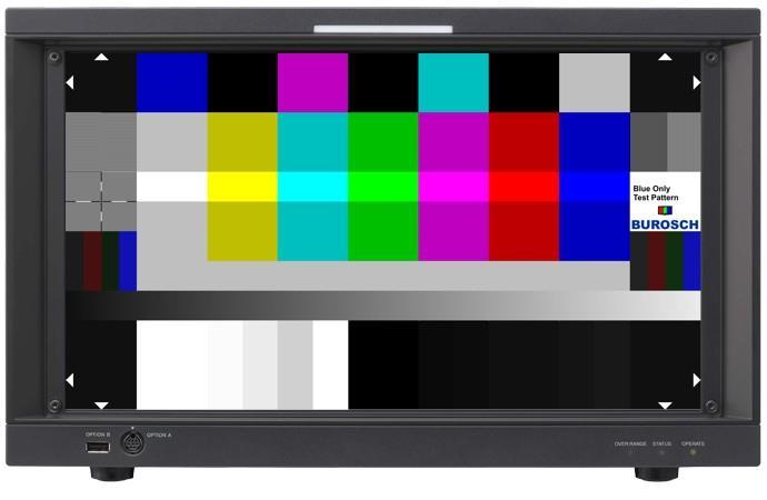
7 Figure The Blue Only test pattern. This is the way your test image should look ideally. BUROSCH TV Image Quality Experts Copyright Page 7 / 36
8 5. The individual picture elements at a glance Figure 5.1 Structure of the Blue Only test pattern with the single 8 bit RGB code values at a glance. See also Chapter 7 BUROSCH TV Image Quality Experts Copyright Page 8 / 36
9 5.1 Line 1 Overscan and Blue Only reference fields Blue Only Test Pattern On the edges of the test pattern are the markings for the overscan function. The white markings are in 8 bit RGB 255 / 255 / 255 coded. The background is black, in 8 bit as 16 / 16 / 16 coded.* Between the image edge markings are alternate color and black areas, which are required to adjust the chrominance (color). This bars are identical to the bars below the color bars in the 4:3 NTSC SMPTE test pattern. * See also chapter and Line 2 interlaced progressiv fields and 75% color bar On the left side is the testing field to check for interlaced or progressive signal transmission. Alongside you see a 7 stripe color bar with 75% luminance. 5.3 Line 3 100% color bar In this line the 7 times color bar has a luminance of 100%. The White Squares, have a code value of 255 / 255 / Line 4 Sharpness test field and 75% color bar See chapter 5.2 As in Line 2 here is a 7 times color bar with 75% luminane located. In addition, located on the edge of the test pattern is a crosshair to adjust the sharpness / aperture. 5.5 Line 5 Rec. 709 / Rec. 601 Luminance signal Y reference field On the left and right side of the test pattern, there are test fields with 4 different vertical color bars. With this test fields you can determine whether the test pattern is transmitted as an SD or HD signal and / or whether the luminance signal Y was calculated correctly according to the SD or HD Standard. In the middle of the test pattern is a gray area with 8 bit RGB code values (235 / 235 / 235) for adjusting the color in the Blue Only mode. 5.6 Line 6 Gray Ramp With this Gray Ramp (the ARIB standard calls it Y ramp signal) quantization errors can easily be detected. In addition, the ramp can help to discover possible non-linear gamma distortions. 5.7 Reihe 7 Overscan and brightness / contrast / Pluge On the edges of the test pattern are markings to adjust the overscan. The white markings are in coded 8 bit RGB with 235 / 235 / 235. The background is black, which in turn is in 8-bit encoded as 16 / 16 / 16.* In between you can see various white and black levels that can be used to adjust brightness and contrast, and also to define the video range (normal range as well as Full or Extended Range) can be verified. Details see Chapter 6.1 and 6.2 BUROSCH TV Image Quality Experts Copyright Page 9 / 36

10 6. The application of the test image, in practice 6.1 In General Before you should adjust your display you should allow the display to warm up, because the imaging elements are temperature dependent and can heat up considerably during operation. Simply swithc the display on 20 minutes before you want to adjust it. This is because the electronic components can change there technical values during this time. Only after this warm up time, a constant display brightness, contrast and color is guaranteed. Please follow the steps in the following order to adjust your screen. 1. Brightness 2. Contrast 3. Color 4. Overscan 5. Sharpness Preferences Luminance Only To adjust the brightness, switch your screen to the Luminance Only mode. If your display does not have such a mode, please adjust the color saturation of the image down to 0, so that you only can see a black-white representation of the test pattern. Alternatively, you can also adjust brightness and contrast in the color view of the test pattern, but in this case, the fields for contrast and brightness are not so clearly visible. Figure Luminance Only view of the test image Determine the video-range (Full / Extended / Normal) BUROSCH TV Image Quality Experts Copyright Page 10 / 36
11 The brightness of a video signal is recorded, transferred, processed and displayed in a variety of video ranges. There are three different Standardized Video Ranges: Video Range Black 8 bit IRE Value White 8 bit IRE Value Normal Extended Full If an image with extended-range values, is shown on a display, which may simply represent normal range, it comes to a so-called clipping. This means that all values that lie below or above the values 16 or 235 will show the values 16 or 235. It s finally not possible to show brighter white or darker black as possible from the system itself. This is illustrated with an example: Let's think about a display, which can only show normal range values. This display will now get an image, which includes dark shades with code values between 0 and 16. The display would this case, show all the shades of gray as a pure black with the code value 16. The values below 16 then are clipped. White values that lie outside of the video range, are also limited to the maximum value of the according video range (clipped). If the display can show full or extended range, it is not a problem to represent a smaller video range. Clipping occurs only with a larger video range, who will be displayed on a device that only supports a smaller video range. In some playback devices, the Extended Range can be explicitly enabled in the menu. This feature is sometimes referred to as Super Black and Super White. One exception is the transmission of color signals, they are always transmitted in the full range. With a quantization of 8 bits, this corresponds to code values from 0 to 255. BUROSCH TV Image Quality Experts Copyright Page 11 / 36
12 Figure The black levels - for adjusting the display brightness - can also be used to evaluate the video range of the signal. Alternatively, the video range of the display device can be determined very easily with our test image. First turn - as described in Chapter your display in the Luminance Only Mode. Adjust the brightness to the maximum value. Now look for luminance differences between each of the six black bars - in the lower right area of the test image when you can see all of the 6 black bars, your disply can show Full Range. However, if you see only a big black bar on the left and right, with two single thin black bars, then your display is only able to play Normal Range. The bars 1, 2, 3 and 4 doe not vary in brightness. In the case of an Extended Range playback, you only see the bars 3, 4, 5 and 6. The bars 1 and 2 appear to you as an area with no obvious differences in brightness. In some cases it s maybe possible, that additional image enhancement algorithms in the device leads to incorrect results with the described method above. So it can for example be, that some units of the normal range (16-235) are converted to Full or Extended Range. This leads inevitably to a different representation. Therefore, please make sure in advance whats the supported video range of your display is. (Manual or ask the manufacturer). You should adjust the black level always according to the video range of the video display. This method of determining the video range is manufacturer independent. You can apply this method for displays or projectors. BUROSCH TV Image Quality Experts Copyright Page 12 / 36

13 Figure Top - Full Range. All six bars of the gray scale are visible. Center - Extended Range. Only the bars 3 to 6 are visible. Below - Normal Range. Only the three right bars are visible. BUROSCH TV Image Quality Experts Copyright Page 13 / 36
 can be visible on the display for your eyes.")
14 6.2 Brightness The most important function that should always be adjusted as the first, is the brightness. Here, the black level depending on the videorange will be adjusted correctly. This ensures, that the finest black shades (dark areas) can be visible on the display for your eyes. Here one must note, that however the setting of the brightness is always a function of the ambient light. This has two consequences. Firstly, it is essential to set the display brighter in a bright environment, than in a dark environment. Second, you should certainly think about re-adjusting, will the ambient light is changing. The crucial elements in the test pattern for the brightness adjustement are the black levels in the lower right area of the test image. Figure 6.2 The lower image area of the test pattern to adjust the brightness. The bars 1 to 6 are emphasized for the figure( white lines). Depending on the video range of your display you will see a similar or different representation. Please read the previous chapter. The video range of your display pretends, which bars you have to use to adjust the brightness. Tip! Sometimes a sophisticated distinction between the different black levels by device-specific gamma curves can be difficult. If you are not able to adjust the brightness of your display like the outlined instructions below, please check, if your display device has activated a special gamma curve or if any other image enhancement algorithms are enabled. BUROSCH TV Image Quality Experts Copyright Page 14 / 36
15 6.2.1 Adjust Brightness - Normal Range Figure For adjusting the brightness in normal range, use the bars 4, 5 and 6. The best way to set the brightness of the display is to set the value in the menu to the mitddle and reduces the brightness now slowly until you can perceive only a minimal difference between the individual bars. If the bar 4 also at maximum brightness setting does not differ from the left-hand bar (1, 2 and 3), the test image is transmitted and / or displayed the normal range. For the right adjustment therefore you have too use the three black bars 4, 5 and 6, lime explained below. Once the bar 5 is minimally brighter than the bar 4, the black level is set correctly. There should still be a recognizable difference between the bar 4 and the bar 5. Please also note that the bar 6 must be a littlebit lighter than the bar 5. If the brightness is set too high, the bars significantly raise from each other and you should reduce the brightness If a transmission takes place with Extended Range or Full Range, you should use the left-hand bar (1.2 and 3) to adjust. (See next chapter) BUROSCH TV Image Quality Experts Copyright Page 15 / 36


16 Figure Above: Here the brightness for normal range is adjusted properly. The bar 4 is minimally darker than the bar 5 and bar 6 is slightly brighter than the other bars. Middle: The bar 4, 5 and 6 differ significantly, and black (bar 3) appear gray. The brightness is set too high. Below: The bars 4, 5 and 6 are not discernible. The brightness is set too low. BUROSCH TV Image Quality Experts Copyright Page 16 / 36
17 6.2.2 Adjust Brightness Extended Range / Full Range Figure To adjust the brightness for extended range use the bars 3 and 4. For Full Range the bars 1 and 2 must be used. Here are the adjustments for Extended Range will be explained. If the beams 1, 2 and 3 are visible at the maximum brightness of the display device, your display device is capable to show Full Range. Then proceed as described for Normal or Extended Range, however, take the bars 1, 2 and 3 as a reference. In the case of Extended Range, the bars 1 and 2 schould show the same Luminance as bar 3. Once the bar 4 is minimally brighter than the bar 3, the black level is set correctly. There should still be a recognizable difference between the bar 3 and the bar 4. Please also note that the bar 5 and 6 must be a littlebit lighter than the bar 4. If the brightness is set too high, the bars significantly raise from each other and you should reduce the brightness If a transmission takes place with Full Range, you should use the left-hand bars (1,2 and 3) to adjust the brightness. Then, the bar 2 should be minimal brighter than bar 1. From left to right, the bars should gradually become lighter. BUROSCH TV Image Quality Experts Copyright Page 17 / 36


18 Figure Above: Here the brightness for extended range is adjusted properly. The bar 3 is minimally darker than the bar 4 and the bars 5 and 6 are slightly brighter than the other bars. Middle: The bars differ significantly, and black appears gray. The brightness is set too high. Below: The bars are not different in brightness. The brightness is set too low. BUROSCH TV Image Quality Experts Copyright Page 18 / 36
19 6.3 Contrast Figure The lower image area of the test pattern to adjust the contrast. The bars 1 to 5 are emphasized for the figure (white lines). Depending on the video range of your display you will see a similar or different representation. Also for adjusting the contrast, the previously described effects of ambient light should be considered. When the ambient light is changing, brightness and contrast should absolutely be readjusted. A change in the contrast efects the bright areas of a video signal. When adjusting the contrast, the aim therefore should be, that the finest levels of brightness in the bright image areas are visible after adjusting. So the contrast should be adjusted that way, that the representation of finest details in bright image areas is possible. As explained the white level also have different code values for Normal, Full and Extended Range. Because the human eye, however, can see brigthness differneces in bright image areas not that goog than luminance changes in dark image areas. So the Video Range should be determined with the black bars. Therefore, please check as described above the video range of your display device. You should use the following bars as a reference, depending on the video range of your display, to adjust the contrast: Video Range Reference Bar (see Figure 6.3.1) Code Value Full Extended Normal Tip! In addition to the fine adjustment of brightness, contrast and to adjust the gamma curve, we recommend our 256 Greystep test pattern, which is available on our Professional Display Tuning Test Disc in our webshop. Moreover, this disc also includes test sequences with real content, to verify the authenticity of skin tones and the quality of color reproduction. BUROSCH TV Image Quality Experts Copyright Page 19 / 36
20 6.3.1 Adjust Contrast Normal Range For adjusting the contrast, the steps are similar to the adjustment of the brightness values. Set the value for the contrast in the menu to the minimum. Adjust the value now slowly up. Once you are able to distinguish the white corresponding to your video range - Normal Range bar 3 (see Figure 6.3.1) - just from the right adjacent bar 4, the contrast is set properly. See Figure Now you can see all the details in the bright areas of the picture (fine brightness gradations). Figure Above: Here the contrast for normal range is adjusted properly. The bar 3 is minimally brighter than the bar 4. Middle: The bars vary significantly. The contrast value is set too low. Below: All the bars have the same brightness. You can t see any differences. The contrast value is set too high. BUROSCH TV Image Quality Experts Copyright Page 20 / 36
21 6.3.2 Adjust Contrast Extended Range / Full Range When the display is able to show extended range, the bar 2 serves as a reference for adjusting the contrast. The bars 1 and 2 in this case should have the same luminane, no matter how you adjust the contrast. If you can see differences between the bar 1 and 2 then please check - as previously described - which video range is supported by your display device. If it is extended range, adjust the contrast so that the bar 3 is just sligtly different from the 2nd bar. In addition, the bar 4 should be minimally darker than the 3rd bar. If you have the contrast of th display correctly adjusted, you can be sure, that you in the future will see all the details in the bright image areas (lights). Figure Above: Here the contrast for extended range is adjusted properly. The bar 2 is minimally brighter than the bar 3. The bar 4 is slightly darker then the Bar 3. Middle: The bars vary significantly. The contrast value is set too low. Below: All the bars have the same brightness. You can t see any differences. The contrast value is set too high. BUROSCH TV Image Quality Experts Copyright Page 21 / 36
22 6.4 Color Before you adjust the menu settings for color, make sure you have correctly set the brightness and contrast functions. As already mentioned, you adjust the color with the help of the Blue Ony Mode. If your display device have such a mode, please activate this. Alternatively, you can rely on a blue filter. As initially mentioned, you just keep this between your eyes and the display. This film is available on request from us. Adjusting the color, you have to use the options Saturation / Chroma and Hue / Phase. These settings are available for broadcast monitors in general. With consumer displays these settings can have a different name or even may not be available. In this case, please take a look at the manual and / or consult your manufacturer Adjust Color If the display is adjusted properly, there should now differences in brightness should be visible between the 75% color bars and the bars above and below the color (reference fields) See Figure for correct settings. The bar in the Blue Only mode are then displayed in a horizontal sequence, alternately light or dark. The 100% color bar in the center of the test pattern are slightly lighter in the colors white, cyan, magenta and blue, than the color bars with 75% saturation. Figure Correctly adjusted color. Between the Bars and the upper and lower bars of the 75% color bars (reference field) is not a recognizable difference in brightness. The color bars are alternately light and dark. For the colors white, cyan, magenta and blue, you can see a brightness difference between 75% and 100% color bar. BUROSCH TV Image Quality Experts Copyright Page 22 / 36
23 6.4.2 Adjust Color Saturation / Chroma When the Saturation / Chroma is set too low or too high you can see a clear difference between the color bar and the areas above and below the color bars (reference fields). In this case, you have to adjusted the saturation as long as there will be no differences in brightness visible (between the color bar and the reference fields below and above the color bars). The bars in horizontal direction should then alternately be light and dark. See Figure Figure Saturation / chroma set incorrectly. In this case, the saturation is too low. The color bars have a different brightness level than the picture elements above and below the color bar. BUROSCH TV Image Quality Experts Copyright Page 23 / 36

24 6.4.3 Adjust Color Hue / Phase If an incorrect Hue / Phase value is set, in the colors cyan, magenta and green brightness differences between the color bar and the reference fields above and below the color bars are visible. In this case, the settings for Hue / Phase must be adjusted, until the swatches have the same brightness as the reference fields. Figure Hue / Phase set wrong. You can see a brightness difference in the patches cyan, magenta and green. BUROSCH TV Image Quality Experts Copyright Page 24 / 36

25 6.5 Image Markers / Overscan With this edge markings, you can check fast and easy check, if your display show a wrong aspect ratio, an pixel shift or an overall overscan.. If your display is set correctly all the triangles in the corners must be completely visible. The corresponding menu option is often referred as overscan, aspect ratio, or pixel to pixel view. Tip! An activated overscan funtion can cause errors in the interlaced progressiv testfield and the sharpness test field. You should adjust the overscan function first, before you try to adjust the other functions. Figure Ausschnitt Left correctly set. Right - wrong settings (overscan enabled) Figure Gesamtansicht Left correctly set. Right - wrong settings (overscan enabled) BUROSCH TV Image Quality Experts Copyright Page 25 / 36
26 6.6 Sharpness / Aperture With the crosshair on the left edge of the test pattern you can adjust the sharpness (sometimes called aperture) correctly. With digital projectors, it is useful to resort to special focus test images from Burosch Audio-Video- Technik, because their lenses sometimes blurring the edge. The same applies for the adjustment of the sharpness with tube TVs. If the sharpness / Aperture is set correctly there should be no double contours visible. In addition, in the interlaced progressive test field no brightness modulations should be visible. See Figure Tip! The settings for overscan have an impact on this test field too. Please adjust the overscan or pixel to pixel view first. Figure Left correctly set. Right - wrong settings (double contours visible) BUROSCH TV Image Quality Experts Copyright Page 26 / 36


27 6.7 Interlaced / Progressiv If you see only a white and a black box, the test image is than transmitted as an interlaced signal. Bei einer progressiven Bildübertragung sehen Sie zwei Felder mit je 1px breiten Linien. Diese Felder sollten bei einer korrekten Darstellung keine Helligkeitsmodulation aufweisen und jede der 1px breiten Linien sollte klar und deutlich (schwarz, weiß) erkennbar sein. Siehe Figure In a progressive image transmission, you will see two boxes, each with 1px wide lines. These fields should show a correct representation without any intensity modulation, and each of the 1px wide lines should be visible. See Figure Tip! As mentioned above, the settings for sharpness and overscan have an impact on this test field too. If you definitely have a progressiv image transmission but you see brightness modulations in this test pattern please recheck the settings for overscan and sharpness. Figure Left - Progressive. Each of the 1px wide lines is visible. Middle - interlaced. The fields are shown in black and white / Right - sharpness / overscan set incorrectly it comes to brightness modulations. The images in this document can show errors through printing or by viewing the document on a monitor. This can affect the color, brightness, contrast and scaling of the shown figures. The figures therefore should only be interpreted as an indication about the possible adjusting effects. BUROSCH TV Image Quality Experts Copyright Page 27 / 36
28 6.8 Rec. 709 / Rec. 601 Luminance signal Y reference field These fields can be used to more easily determine which standard (SD or HD), the signal is present, or whether the calculation of the luminance signal is correct or there has been a transformation of the signal. For SD there is the color standard REC.601 whereas in HD, a new standard was introduced, REC.709. Among other things, the difference between these two standards are the calculation of the Luminance Signal Y. Both standards operate on the Y `CbCr process in which the luminance signal Y (luminance - or brightness signal) is determined from the three primary colors with the help of coefficients. These coefficients take into account the brightness rating for different colors. So the human eye sees blue shades darker than the - for example - green colors. The formulas for the luminance signal Y at SD and HD: SD / Rec. 601 Y' = R' G' B' HD / Rec. 709 Y' = R' G' B' The colors in this test field are arranged so that in the Luminance mode you will see a uniform, equally bright surface. So if you e.g. can identify individual bars in the left test field, the signal is transfered in the SD standard REC 601. The right box should therefore form a uniform dark area. All bars in the ares should have the same brightness. Unfortunately it can sometimes lead to errors in the representation of colors by the display devices internal color space transformations or improvements. If your display device shows such a behavior, please check whether your display has such functions and whether these can be disabled. BUROSCH TV Image Quality Experts Copyright Page 28 / 36
29 Rec. 709 Luminance Only view of the Blue Only test pattern Rec. 709 Rec. 601 Rec. 601 Luminance Only view of the Blue Only test pattern Rec. 601 Rec. 709 Figure Above Rec. 709 / HD Below Rec. 601 / SD BUROSCH TV Image Quality Experts Copyright Page 29 / 36
30 6.9 Gray ramp signal Use this brightness gradient (gray ramp) of 16 / 16 / 16 (black) to 235 / 235 / 235 (white), which runs diagonally - from the upper left corner to the lower right corner to see quantization or clipping errors. In addition, the correct adjustment of brightness and contrast can be checked again. See Figure Figure Above Brightness and contrast are set incorrectly. Clipping in whit and black areas. Below Extreme quantization errors, you can see banding effects. The ramp is no longer uniform and shows the subtle shades of gray in different steps. BUROSCH TV Image Quality Experts Copyright Page 30 / 36
31 7. Waveform and vectorscope display of the individual picture elements Figure 7.a Structure of the Blue Only test pattern with the different code values at a glance. BUROSCH TV Image Quality Experts Copyright Page 31 / 36
32 Figure 7.b Structure of the Blue Only test pattern with the various Lines at a glance. BUROSCH TV Image Quality Experts Copyright Page 32 / 36
33 7.1 Vectorscope Display Figure 7.a shows the structure of the Blue Only test image with the 8 bit code values in RGB. 75% Yellow 191 / 191 / 0 means Red = 191 Green = 191 and Blue = 0 The following figuree show the overall view and excerpts of the vectorscope image. This test image was not explicitly designed for the use with a vectorscope, so it can be difficult to interprate the image content. To achieve a correct representation of the vectorscope, the targets have to be for the HD color space REC.709. Figure Vectorscope display of the whole Blue Only test pattern. Figure Detail Vectorscope display of the 75% und 100% - color bars. BUROSCH TV Image Quality Experts Copyright Page 33 / 36


34 7.2 Waveform Display The following figures show the entire test image in different waveform representations. Figure Waveform Display Parade RGB Figure Waveform Y-Signal Voltages in volts. BUROSCH TV Image Quality Experts Copyright Page 34 / 36


35 8. Test Pattern in practice Figure 8.1 The Blue Only test image with blue filter in use Figure 8.2 The Blue Only test pattern on two standard definition CRT displays. Left - Luminance Only Mode Right - Blue Only mode. BUROSCH TV Image Quality Experts Copyright Page 35 / 36
36 9. Glossary The images in this document can show errors through printing or by viewing the document on a monitor. This can affect the color, brightness, contrast and scaling of the shown figures. The figures therefore should only be interpreted as an indication about the possible adjusting effects. 10. Imprint BUROSCH Audio-Video-Technik Owner: Klaus Burosch Sigmaringer Str Stuttgart / Germany Phone: (0) Fax: (0) Mail: info@burosch.de Our products are internationally protected by copyright and for private use only. For commercial use a special business license has to be ordered. Please contact us if you need a business license. In case of acquisition you acquire a single-license and accept our general terms and conditions of act. Terms and technical data can change without official notice. We take no responsibility for direct and indirect damages occurred by an improper use of our products. Copyright - All Rights Reserved. BUROSCH Audio Video Technik BUROSCH TV Image Quality Experts Copyright Page 36 / 36
First TV Tuning Reference Test Pattern Technical description and application
 First TV Tuning Reference Test Pattern Technical description and application Content Introduction... 4 1. Overscan / Picture Format... 5 2. Brightness... 6 3. Contrast... 7 4. Color... 8 5. Sharpness /
Using the VP300 to Adjust Video Display User Controls
 Using the VP300 to Adjust Video Display User Controls Today's technology has produced extraordinary improvements in video picture quality, making it possible to have Cinema-like quality video right in
High-Definition, Standard-Definition Compatible Color Bar Signal
 Page 1 of 16 pages. January 21, 2002 PROPOSED RP 219 SMPTE RECOMMENDED PRACTICE For Television High-Definition, Standard-Definition Compatible Color Bar Signal 1. Scope This document specifies a color
AJ-PX270 SCENE FILE SETTINGS PROFESSIONAL HANDBOOK
 AJ-PX270 SCENE FILE SETTINGS PROFESSIONAL HANDBOOK --- Table of contents --- 1. Selecting Scene File... 3 1-1. Scene Files and their features... 3 1-2. Table of Factory Default Settings... 4 2. Expressing
Patterns Manual September 16, Main Menu Basic Settings Misc. Patterns Definitions
 Patterns Manual September, 0 - Main Menu Basic Settings Misc. Patterns Definitions Chapters MAIN MENU episodes through, and they used an earlier AVS HD 0 version for the demonstrations. While some items,
User's Manual. Rev 1.0
 User's Manual Rev 1.0 Digital TV sales have increased dramatically over the past few years while the sales of analog sets are declining precipitously. First quarter of 2005 has brought the greatest volume
Reference Test Pattern
 Pixel Cropping Reference Test Pattern www.burosch.de The pixel cropping test pattern shows a lot of possibilities for image calibration and quality evaluation without measurement devices especially for
NAPIER. University School of Engineering. Advanced Communication Systems Module: SE Television Broadcast Signal.
 NAPIER. University School of Engineering Television Broadcast Signal. luminance colour channel channel distance sound signal By Klaus Jørgensen Napier No. 04007824 Teacher Ian Mackenzie Abstract Klaus
Power Consumption Measurement according to IEC EuP Measurement Sharp Aquos LC-46LE700E
 Power Consumption Measurement according to IEC 62087 EuP Measurement Sharp Aquos LC-46LE700E Burosch Audio-Video-Technik Power Consumption Measurement www.burosch.de 15.12.2009 Page 1 A. Introduction Only
Crystal Sanchez Video Preservation 1 December Video Preservation Project: No Setup vs. Setup
 Crystal Sanchez Video Preservation 1 December 2011 Video Preservation Project: No Setup vs. Setup When doing transfers of analog video materials, there are a variety of choices available to the preservation
ADJUSTABLE RANGE OF PARAMETERS [End of the Book]
![ADJUSTABLE RANGE OF PARAMETERS [End of the Book]](/thumbs/88/117180687.jpg "ADJUSTABLE RANGE OF PARAMETERS [End of the Book]") Page Introduction FEATURE OF AG-HPX250 S BUILT-IN SENSOR 2 Chapter 1. SCENE FILE 4 Chapter 2. DETAIL / V DETAIL 6 Chapter 3. KNEE 8 Chapter 4. GAMMA 10 Chapter 5. DRS 12 Chapter 6. DETAIL CORING /SKIN
Page Introduction FEATURE OF AG-HPX250 S BUILT-IN SENSOR 2 Chapter 1. SCENE FILE 4 Chapter 2. DETAIL / V DETAIL 6 Chapter 3. KNEE 8 Chapter 4. GAMMA 10 Chapter 5. DRS 12 Chapter 6. DETAIL CORING /SKIN
decodes it along with the normal intensity signal, to determine how to modulate the three colour beams.
 Television Television as we know it today has hardly changed much since the 1950 s. Of course there have been improvements in stereo sound and closed captioning and better receivers for example but compared
ANTENNAS, WAVE PROPAGATION &TV ENGG. Lecture : TV working
 ANTENNAS, WAVE PROPAGATION &TV ENGG Lecture : TV working Topics to be covered Television working How Television Works? A Simplified Viewpoint?? From Studio to Viewer Television content is developed in
Communication Theory and Engineering
 Communication Theory and Engineering Master's Degree in Electronic Engineering Sapienza University of Rome A.A. 2018-2019 Practice work 14 Image signals Example 1 Calculate the aspect ratio for an image
ESI VLS-2000 Video Line Scaler
 ESI VLS-2000 Video Line Scaler Operating Manual Version 1.2 October 3, 2003 ESI VLS-2000 Video Line Scaler Operating Manual Page 1 TABLE OF CONTENTS 1. INTRODUCTION...4 2. INSTALLATION AND SETUP...5 2.1.Connections...5
Using Low-Cost Plasma Displays As Reference Monitors. Peter Putman, CTS, ISF President, ROAM Consulting LLC Editor/Publisher, HDTVexpert.
 Using Low-Cost Plasma Displays As Reference Monitors Peter Putman, CTS, ISF President, ROAM Consulting LLC Editor/Publisher, HDTVexpert.com Time to Toss The CRT Advantages: CRTs can scan multiple resolutions
AVIA Professional A multi-disc calibration, set-up and test suite Developed by: Ovation Multimedia, Inc. July, 2003
 AVIA Professional A multi-disc calibration, set-up and test suite Developed by: Ovation Multimedia, Inc. July, 2003 AVIA Professional General Information What is AVIA Professional? AVIA Professional (AVIA
Chapter 3 Fundamental Concepts in Video. 3.1 Types of Video Signals 3.2 Analog Video 3.3 Digital Video
 Chapter 3 Fundamental Concepts in Video 3.1 Types of Video Signals 3.2 Analog Video 3.3 Digital Video 1 3.1 TYPES OF VIDEO SIGNALS 2 Types of Video Signals Video standards for managing analog output: A.
Display-Shoot M642HD Plasma 42HD. Re:source. DVS-5 Module. Dominating Entertainment. Revox of Switzerland. E 2.00
 of Display-Shoot M642HD Plasma 42HD DVS-5 Module Dominating Entertainment. Revox of Switzerland. E 2.00 Contents DVS Module Installation DSV Connection Panel HDMI output YCrCb analogue output DSV General
Ch. 1: Audio/Image/Video Fundamentals Multimedia Systems. School of Electrical Engineering and Computer Science Oregon State University
 Ch. 1: Audio/Image/Video Fundamentals Multimedia Systems Prof. Ben Lee School of Electrical Engineering and Computer Science Oregon State University Outline Computer Representation of Audio Quantization
Achieve Accurate Critical Display Performance With Professional and Consumer Level Displays
 Achieve Accurate Critical Display Performance With Professional and Consumer Level Displays Display Accuracy to Industry Standards Reference quality monitors are able to very accurately reproduce video,
Dan Schuster Arusha Technical College March 4, 2010
 Television Theory Of Operation Dan Schuster Arusha Technical College March 4, 2010 My TV Background 34 years in Automation and Image Electronics MS in Electrical and Computer Engineering Designed Television
DCI Requirements Image - Dynamics
 DCI Requirements Image - Dynamics Matt Cowan Entertainment Technology Consultants www.etconsult.com Gamma 2.6 12 bit Luminance Coding Black level coding Post Production Implications Measurement Processes
Television History. Date / Place E. Nemer - 1
 Television History Television to see from a distance Earlier Selenium photosensitive cells were used for converting light from pictures into electrical signals Real breakthrough invention of CRT AT&T Bell
Understanding PQR, DMOS, and PSNR Measurements
 Understanding PQR, DMOS, and PSNR Measurements Introduction Compression systems and other video processing devices impact picture quality in various ways. Consumers quality expectations continue to rise
Calibrating the timecode signal input
 Chapter 5 Calibrating the timecode signal input Computer hardware can introduce an offset between the timecode signal and the video signal, which causes the timecode and video to be offset when they are
Evaluation Monitors and Projectors
 Evaluation Monitors and Projectors Benchmarks and Observed Performance of LCD, Plasma, DLP, HTPS LCD, and LCoS Grayscale Attributes Dynamic Range Most LCD and plasma displays run too hot and cannot achieve
RECOMMENDATION ITU-R BT (Question ITU-R 211/11)
") Rec. ITU-R T.814-1 1 RECOMMENDATION ITU-R T.814-1 SPECIICATIONS AND ALIGNMENT PROCEDURES OR SETTING O RIGTNESS AND CONTRAST O DISPLAYS (Question ITU-R 211/11) Rec. ITU-R T.814-1 (1992-1994) The ITU Radiocommunication
Rec. ITU-R T.814-1 1 RECOMMENDATION ITU-R T.814-1 SPECIICATIONS AND ALIGNMENT PROCEDURES OR SETTING O RIGTNESS AND CONTRAST O DISPLAYS (Question ITU-R 211/11) Rec. ITU-R T.814-1 (1992-1994) The ITU Radiocommunication
User requirements for a Flat Panel Display (FPD) as a Master monitor in an HDTV programme production environment. Report ITU-R BT.
 as a Master monitor in an HDTV programme production environment. Report ITU-R BT.") Report ITU-R BT.2129 (05/2009) User requirements for a Flat Panel Display (FPD) as a Master monitor in an HDTV programme production environment BT Series Broadcasting service (television) ii Rep. ITU-R
Report ITU-R BT.2129 (05/2009) User requirements for a Flat Panel Display (FPD) as a Master monitor in an HDTV programme production environment BT Series Broadcasting service (television) ii Rep. ITU-R
Digital Media. Daniel Fuller ITEC 2110
 Digital Media Daniel Fuller ITEC 2110 Daily Question: Video In a video file made up of 480 frames, how long will it be when played back at 24 frames per second? Email answer to DFullerDailyQuestion@gmail.com
Calibration Best Practices
 Calibration Best Practices for Manufacturers By Tom Schulte SpectraCal, Inc. 17544 Midvale Avenue N., Suite 100 Shoreline, WA 98133 (206) 420-7514 info@spectracal.com http://studio.spectracal.com Calibration
iii Table of Contents
 i iii Table of Contents Display Setup Tutorial....................... 1 Launching Catalyst Control Center 1 The Catalyst Control Center Wizard 2 Enabling a second display 3 Enabling A Standard TV 7 Setting
united.screens GmbH FUTURE DISPLAY TECHNOLOGY 2017 united.screens GmbH
 united.screens GmbH FUTURE DISPLAY TECHNOLOGY T-OLED CRYSTALSCREEN Content Developer s Guide Index How transparent OLEDs work 03 History of OLEDs 03 Pixelstructure 03 Content Development 04 Differences
Company Software Manual version Issued Date Sony Corporation Projector Calibration Pro Version 0.04 Mar 3rd, 2017
 1 A. Equipment Required B. Corresponding projectors / Functions C. Preparation D. Functions E. Note 1. Equipment Required - Software: Projector Calibration Pro - Sony Projector with LAN port
Learning to Use The VG91 Universal Video Generator
 Learning to Use The VG91 Universal Video Generator Todays TV-video systems can be divided into 3 sections: 1) Tuner/IF, 2) Video and 3) Audio. The VG91 provides signals to fully test and isolate defects
Preventing Illegal Colors
 Test Equipment Depot - 800.517.8431-99 Washington Street Melrose, MA 02176 - TestEquipmentDepot.com Preventing Illegal Colors Application Note Color gamut compliance is important to ensure faithful reproduction
DRAFT. Proposal to modify International Standard IEC
 Imaging & Color Science Research & Product Development 2528 Waunona Way, Madison, WI 53713 (608) 222-0378 www.lumita.com Proposal to modify International Standard IEC 61947-1 Electronic projection Measurement
Instruction Manual. 1 Page
 Instruction Manual 1 Page Introduction A reference pattern generator is an essential piece of equipment in the video calibration process. Most, if not all, certified and experienced calibrators utilize
Designing Custom DVD Menus: Part I By Craig Elliott Hanna Manager, The Authoring House at Disc Makers
 Designing Custom DVD Menus: Part I By Craig Elliott Hanna Manager, The Authoring House at Disc Makers DVD authoring software makes it easy to create and design template-based DVD menus. But many of those
The Extron MGP 464 is a powerful, highly effective tool for advanced A/V communications and presentations. It has the
 MGP 464: How to Get the Most from the MGP 464 for Successful Presentations The Extron MGP 464 is a powerful, highly effective tool for advanced A/V communications and presentations. It has the ability
Traditionally video signals have been transmitted along cables in the form of lower energy electrical impulses. As new technologies emerge we are
 2 Traditionally video signals have been transmitted along cables in the form of lower energy electrical impulses. As new technologies emerge we are seeing the development of new connection methods within
Display Systems. Viewing Images Rochester Institute of Technology
 Display Systems Viewing Images 1999 Rochester Institute of Technology In This Section... We will explore how display systems work. Cathode Ray Tube Television Computer Monitor Flat Panel Display Liquid
Lecture 2 Video Formation and Representation
 2013 Spring Term 1 Lecture 2 Video Formation and Representation Wen-Hsiao Peng ( 彭文孝 ) Multimedia Architecture and Processing Lab (MAPL) Department of Computer Science National Chiao Tung University 1
VIDEO 101 LCD MONITOR OVERVIEW
 VIDEO 101 LCD MONITOR OVERVIEW This provides an overview of the monitor nomenclature and specifications as they relate to TRU-Vu industrial monitors. This is an ever changing industry and as such all specifications
Colour Reproduction Performance of JPEG and JPEG2000 Codecs
 Colour Reproduction Performance of JPEG and JPEG000 Codecs A. Punchihewa, D. G. Bailey, and R. M. Hodgson Institute of Information Sciences & Technology, Massey University, Palmerston North, New Zealand
To show the Video Scopes, click on the down arrow next to View located in the upper- right corner of your playback panel.
 1 FCPX: 3.3 COLOR CORRECTION Color Correcting and Color Grading are usually the last things you do before exporting your video. Color Correcting is the process of achieving the correct, natural color of
Multimedia Systems Video I (Basics of Analog and Digital Video) Mahdi Amiri April 2011 Sharif University of Technology
 Mahdi Amiri April 2011 Sharif University of Technology") Course Presentation Multimedia Systems Video I (Basics of Analog and Digital Video) Mahdi Amiri April 2011 Sharif University of Technology Video Visual Effect of Motion The visual effect of motion is due
Course Presentation Multimedia Systems Video I (Basics of Analog and Digital Video) Mahdi Amiri April 2011 Sharif University of Technology Video Visual Effect of Motion The visual effect of motion is due
Presented by: Amany Mohamed Yara Naguib May Mohamed Sara Mahmoud Maha Ali. Supervised by: Dr.Mohamed Abd El Ghany
 Presented by: Amany Mohamed Yara Naguib May Mohamed Sara Mahmoud Maha Ali Supervised by: Dr.Mohamed Abd El Ghany Analogue Terrestrial TV. No satellite Transmission Digital Satellite TV. Uses satellite
Model 7405 High Definition Test Signal Generator Data Pack
 Model 7405 High Definition Test Signal Generator Data Pack E NSEMBLE D E S I G N S Revision 1.1 SW v1.1.0 This data pack provides detailed installation, configuration and operation information for the
Understanding Human Color Vision
 Understanding Human Color Vision CinemaSource, 18 Denbow Rd., Durham, NH 03824 cinemasource.com 800-483-9778 CinemaSource Technical Bulletins. Copyright 2002 by CinemaSource, Inc. All rights reserved.
The XYZ Colour Space. 26 January 2011 WHITE PAPER. IMAGE PROCESSING TECHNIQUES
 www.omnitek.tv IMAE POESSIN TEHNIQUES The olour Space The colour space has the unique property of being able to express every colour that the human eye can see which in turn means that it can express every
Spearhead Display. How To Guide
 Spearhead Display The Tektronix color tool set has always been about allowing the user to marry the Art & Science irrespective of the color space they are working in. How To Guide How To Guide Figure 1.
4KScope Software Waveform, Vectorscope, Histogram and Monitor
 4KScope - a 4K/2K/HD/SD Video Measurement Tool View your color bars, test patterns, live camera or telecine signal for device or facility installation, setup, commissioning/certification and other operational
Video Signals and Circuits Part 2
 Video Signals and Circuits Part 2 Bill Sheets K2MQJ Rudy Graf KA2CWL In the first part of this article the basic signal structure of a TV signal was discussed, and how a color video signal is structured.
How to Chose an Ideal High Definition Endoscopic Camera System
 How to Chose an Ideal High Definition Endoscopic Camera System Telescope Laparoscopy (from Greek lapara, "flank or loin", and skopein, "to see, view or examine") is an operation performed within the abdomen
Audio and Video II. Video signal +Color systems Motion estimation Video compression standards +H.261 +MPEG-1, MPEG-2, MPEG-4, MPEG- 7, and MPEG-21
 Audio and Video II Video signal +Color systems Motion estimation Video compression standards +H.261 +MPEG-1, MPEG-2, MPEG-4, MPEG- 7, and MPEG-21 1 Video signal Video camera scans the image by following
Monitoring HD and SD Color Gamut in a Broadcast Environment
 Monitoring HD and SD Color Gamut in a Broadcast Environment Basics of RGB and composite color space, introducing an efficient way to monitor color gamut problems #1 The RGB Principle With 3 light sources
The Development of a Synthetic Colour Test Image for Subjective and Objective Quality Assessment of Digital Codecs
 2005 Asia-Pacific Conference on Communications, Perth, Western Australia, 3-5 October 2005. The Development of a Synthetic Colour Test Image for Subjective and Objective Quality Assessment of Digital Codecs
Colour Matching Technology
 Colour Matching Technology For BVM-L Master Monitors www.sonybiz.net/monitors Colour Matching Technology BVM-L420/BVM-L230 LCD Master Monitors LCD Displays have come a long way from when they were first
OPERATING GUIDE. M-Vision Cine 3D series. High Brightness Digital Video Projector 16:9 widescreen display. Rev A August A
 OPERATING GUIDE M-Vision Cine 3D series High Brightness Digital Video Projector 16:9 widescreen display 112-022A Digital Projection M-Vision Cine 3D series CONTENTS Operating Guide CONTENTS About this
BUREAU OF ENERGY EFFICIENCY
 Date: 26 th May, 2016 Schedule No.: 11 Color Televisions 1. Scope This schedule specifies the energy labeling requirements for color televisions with native resolution upto 1920 X 1080 pixels, of CRT,
Superior Digital Video Images through Multi-Dimensional Color Tables
 Superior Digital Video Images through Multi-Dimensional Color Tables TruVue eecolor Technology White Paper Jim Sullivan CEO, Entertainment Experience, LLC About the Author Jim Sullivan joined Entertainment
TECHNICAL SUPPLEMENT FOR THE DELIVERY OF PROGRAMMES WITH HIGH DYNAMIC RANGE
 TECHNICAL SUPPLEMENT FOR THE DELIVERY OF PROGRAMMES WITH HIGH DYNAMIC RANGE Please note: This document is a supplement to the Digital Production Partnership's Technical Delivery Specifications, and should
Mike Robin MIKE ROBIN S COLUMN SEPTEMBER Introduction. Generation of a color bars signal
 MIKE OIN S COLUMN SEPTEME 1999 Mike obin, a 2-year veteran of the Canadian roadcasting Corporation Engineering Headquarters, is an independent broadcast consultant located in Montreal, Canada. He is the
!"#"$%& Some slides taken shamelessly from Prof. Yao Wang s lecture slides
 http://ekclothing.com/blog/wp-content/uploads/2010/02/spring-colors.jpg Some slides taken shamelessly from Prof. Yao Wang s lecture slides $& Definition of An Image! Think an image as a function, f! f
Avia PRO Video Test DVD
 Avia PRO Video Test DVD Guy Kuo, Ovation Multimedia, Inc. Introduction This chapter discusses the video test signals found on the Avia PRO Video Test DVD and its supplemental 4:3 Ratio DVD. Avia PRO contains
Color Correction in Final Cut Studio Introduction to Color
 Color Correction in Final Cut Studio Introduction to Color Part 1: Getting Started with Color Part 2: Managing and Applying Grades upart 3: Using the Scopes and Auto Balanceo Part 4: Copying from One Clip
Discreet Logic Inc., All Rights Reserved. This documentation contains proprietary information of Discreet Logic Inc. and its subsidiaries.
 Discreet Logic Inc., 1996-2000. All Rights Reserved. This documentation contains proprietary information of Discreet Logic Inc. and its subsidiaries. No part of this documentation may be reproduced, stored
quantumdata 980 Series Test Systems Overview of UHD and HDR Support
 quantumdata 980 Series Test Systems Overview of UHD and HDR Support quantumdata 980 Test Platforms 980B Front View 980R Front View 980B Advanced Test Platform Features / Modules 980B Test Platform Standard
sdiscope Signal Analysis Software Version 6
 sdiscope Signal Analysis Software Version 6 Table of Contents About sdiscope...3 Reference...5 Main Interface Overview...5 Settings Window...11 Data View...16 Picture...17 Vectorscope...19 Vectorscope
Remote Director. Apple 23 LCD Display. Collaborative Soft Proofing using the I. MANUFACTURER INTRODUCTION. SWOP Application Data Sheet
 SWOP Application Data Sheet Remote Director Collaborative Soft Proofing using the Apple 23 LCD Display The SWOP Review Committee has approved the use of off-press proofs as input material to publications.
RECOMMENDATION ITU-R BT (Questions ITU-R 25/11, ITU-R 60/11 and ITU-R 61/11)
") Rec. ITU-R BT.61-4 1 SECTION 11B: DIGITAL TELEVISION RECOMMENDATION ITU-R BT.61-4 Rec. ITU-R BT.61-4 ENCODING PARAMETERS OF DIGITAL TELEVISION FOR STUDIOS (Questions ITU-R 25/11, ITU-R 6/11 and ITU-R 61/11)
Rec. ITU-R BT.61-4 1 SECTION 11B: DIGITAL TELEVISION RECOMMENDATION ITU-R BT.61-4 Rec. ITU-R BT.61-4 ENCODING PARAMETERS OF DIGITAL TELEVISION FOR STUDIOS (Questions ITU-R 25/11, ITU-R 6/11 and ITU-R 61/11)
DCI Memorandum Regarding Direct View Displays
 1. Introduction DCI Memorandum Regarding Direct View Displays Approved 27 June 2018 Digital Cinema Initiatives, LLC, Member Representatives Committee Direct view displays provide the potential for an improved
Fundamentals of Multimedia. Lecture 3 Color in Image & Video
 Fundamentals of Multimedia Lecture 3 Color in Image & Video Mahmoud El-Gayyar elgayyar@ci.suez.edu.eg Mahmoud El-Gayyar / Fundamentals of Multimedia 1 Black & white imags Outcomes of Lecture 2 1 bit images,
V-MD1012. Dual 10.1 Rack Mount Monitor with Modular Input / Output. User Manual
 Dual 10.1 Rack Mount Monitor with Modular Input / Output User Manual Table of Contents 1. Introduction, Installation and Setup... 3 2. Product Overview & Features... 4 3. Dimensions... 8 4. Navigation
Pablo II. The Picasso IV video-encoder. Manual. 18 August Copyright c 1997 Village Tronic Marketing GmbH Mühlenstraße Sarstedt Germany
 Pablo II The Picasso IV video-encoder Manual 18 August 1997 Copyright c 1997 Village Tronic Marketing GmbH Mühlenstraße 2 31157 Sarstedt Germany Technical Hotline: Tel. +49 (0)5066 / 7013-10 FAX: Tel.
Click on the chapter below to navigate to the corresponding section of this document.
 The following are delivery specifications for PANDA 23 both physical and digital. Regardless of delivery method the following specifications must be adhered to in order to run programming on PANDA 23.
High-resolution screens have become a mainstay on modern smartphones. Initial. Displays 3.1 LCD
 3 Displays Figure 3.1. The University of Texas at Austin s Stallion Tiled Display, made up of 75 Dell 3007WPF LCDs with a total resolution of 307 megapixels (38400 8000 pixels) High-resolution screens
Calibrating and Profiling Your Monitor
 Calibrating and Profiling Your Monitor For this module, you will need: Eye-One measurement device Counterweight (used for LCD screens only) New, modern displays are better First, you need to use a good
DLA-X7 DLA-X3. 3D Enabled D-ILA Projectors. *Optional 3D Glasses (PK-AG1) and 3D Synchro Emitter (PK-EM1) are required for viewing images in 3D.
 and 3D Synchro Emitter (PK-EM1) are required for viewing images in 3D.") 3D Enabled D-ILA Projectors *Optional 3D Glasses (PK-AG1) and 3D Synchro Emitter (PK-EM1) are required for viewing images in 3D. Exquisitely natural textures and film-like picture quality JVC s new D-ILA
3D Enabled D-ILA Projectors *Optional 3D Glasses (PK-AG1) and 3D Synchro Emitter (PK-EM1) are required for viewing images in 3D. Exquisitely natural textures and film-like picture quality JVC s new D-ILA
VeriLUM 5.2. Video Display Calibration And Conformance Tracking. IMAGE Smiths, Inc. P.O. Box 30928, Bethesda, MD USA
 VeriLUM 5.2 Video Display Calibration And Conformance Tracking IMAGE Smiths, Inc. P.O. Box 30928, Bethesda, MD 20824 USA Voice: 240-395-1600 Fax: 240-395-1601 Web: www.image-smiths.com Technical Support
Marshall Electronics. Model No.V-LCD90MD 9 Camera-Top Monitor with Modular Input/Output. Operating Instructions Edition 3 Revision 6W
 Marshall Electronics Model No.V-LCD90MD 9 Camera-Top Monitor with Modular Input/Output Operating Instructions Edition 3 Revision 6W 1 2 This page intentionally left blank Table of Contents Installation
Full High Definition Home Cinema Projector PT-AE1000
 Full High Definition Home Cinema Projector PT-AE1000 PT-AE1000 - Outline Model no. PT-AE1000 Display device 0.74 C2Fine LCD panels (16:9 aspect ratio) Resolution 1920 x 1080 (native) Brightness 1,100 lumens
MODEL NUMBER PVM-20L5
 BID SPECIFICATION FOR PRODUCTION CRT MONITORS MODEL NUMBER PVM-20L5 INSTRUCTIONS: REMOVE THIS COVER PAGE AND ADD TO REQUESTS FOR QUOTATION AND PROPOSALS. THE OBJECTIVE OF THIS BID SPECIFICATION IS TO ASSIST
Colorimetric and Resolution requirements of cameras
 Colorimetric and Resolution requirements of cameras Alan Roberts ADDENDUM 55 : Tests and Settings on a Ikegami HDK-79EXIII Data for this section is taken from parts of the handbook and examination of a
ELECTRICAL ADJUSTMENT INSTRUCTIONS
 ELECTRICAL ADJUSTMENT INSTRUCTIONS General Note: "CBA" is abbreviation for "Circuit Board Assembly." NOTE: Electrical adjustments are required after replacing circuit components and certain mechanical
PanelView 1400e CRT Maintenance
 Release Note PanelView 1400e CRT Maintenance Maximizing the life of your PanelView 1400e, CRT Terminals To maximize the life of a CRT, the following is strongly recommended: Adjust the external brightness
SM02. High Definition Video Encoder and Pattern Generator. User Manual
 SM02 High Definition Video Encoder and Pattern Generator User Manual Revision 0.2 20 th May 2016 1 Contents Contents... 2 Tables... 2 Figures... 3 1. Introduction... 4 2. acvi Overview... 6 3. Connecting
An Overview of Video Coding Algorithms
 An Overview of Video Coding Algorithms Prof. Ja-Ling Wu Department of Computer Science and Information Engineering National Taiwan University Video coding can be viewed as image compression with a temporal
Operating Instructions
 Broadcast A/V Division Model No. M-LYNX-702W Dual 7 High Resolution Rack Mount Display with Waveform Operating Instructions V.1.0 Table of Contents 1. PRODUCT DESCRIPTION... 3 2. MENU SETTING... 6 3. SPECIFICATIONS...
EBU Digital AV Sync and Operational Test Pattern
 www.lynx-technik.com EBU Digital AV Sync and Operational Test Pattern Date: Feb 2008 Revision : 1.3 Disclaimer. This pattern is not standardized or recognized by the EBU. This derivative has been developed
Video Projector. Operating Instructions VPL-HW55ES (1)
") 4-538-938-12 (1) Video Projector Operating Instructions Before operating the unit, please read this manual and supplied Quick Reference Manual thoroughly and retain them for future reference. VPL-HW55ES
4-538-938-12 (1) Video Projector Operating Instructions Before operating the unit, please read this manual and supplied Quick Reference Manual thoroughly and retain them for future reference. VPL-HW55ES
RECOMMENDATION ITU-R BT Studio encoding parameters of digital television for standard 4:3 and wide-screen 16:9 aspect ratios
 ec. ITU- T.61-6 1 COMMNATION ITU- T.61-6 Studio encoding parameters of digital television for standard 4:3 and wide-screen 16:9 aspect ratios (Question ITU- 1/6) (1982-1986-199-1992-1994-1995-27) Scope
Marshall Electronics. V-LCD101MD 10.1 Camera-Top Monitor with Modular Input/Output. Operating Instructions. Model No.
 Marshall Electronics Model No. V-LCD101MD 10.1 Camera-Top Monitor with Modular Input/Output Operating Instructions ICW 11-30-2016 Marshall Electronics, Inc. 20608 Madrona Ave Torrance, CA 90503 Tel: (800)
Reading. 1. Displays and framebuffers. History. Modern graphics systems. Required
 Reading Required 1. Displays and s Angel, pp.19-31. Hearn & Baker, pp. 36-38, 154-157. OpenGL Programming Guide (available online): First four sections of chapter 2 First section of chapter 6 Optional
High Value-Added IT Display - Technical Development and Actual Products
 High Value-Added IT Display - Technical Development and Actual Products ITAKURA Naoki, ITO Tadayuki, OOKOSHI Yoichiro, KANDA Satoshi, MUTO Hideaki Abstract The multi-display expands the desktop area to
TECH 3320 USER REQUIREMENTS FOR VIDEO MONITORS IN TELEVISION PRODUCTION
 TECH 3320 USER REQUIREMENTS FOR VIDEO MONITORS IN TELEVISION PRODUCTION VERSION 4.0 Geneva September 2017 This page and several other pages in the document are intentionally left blank. This document is
VP2780-4K. Best for CAD/CAM, photography, architecture and video editing.
 VP2780-4K Best for CAD/CAM, photography, architecture and video editing. The 27 VP2780-4K boasts an ultra-high 3840 x 2160 4K UHD resolution with 8 million pixels for ultimate image quality. The SuperClear
SX7. Saga 7" Super Bright HDMI/3G-SDI Field Monitor with 3D-LUTs. Quick Start Guide. What s Included CHECKED BY
 SX7 Quick Start Guide Saga 7" Super Bright HDMI/3G-SDI Field Monitor with 3D-LUTs What s Included 1 x Saga X7 Monitor 1 x V-Mount Plate (Attached) 1 x Mini-XLR to P-TAP Cable 1 x Dual Sony L Battery Adapter
HDR & WIDE COLOR GAMUT
 HDR & WIDE COLOR GAMUT How do we get there and remaining backwards compatible Peter Schut, CTO VP of R&D peter.schut@axon.tv www.axon.tv IN THIS PRESENTATION Some Basics Stuff that puzzled me, maybe puzzles