Dualband Feed for EsHail-2 / Qatar-OSCAR 100 Matthias, DD1US, , Rev 0.8
|
|
|
- Andrew Marshall
- 5 years ago
- Views:
Transcription


1 Dualband Feed for EsHail-2 / Qatar-OSCAR 100 Matthias, DD1US, , Rev 0.8 Hello, Now that EsHail-2 has been successfully launched and has started its regular operation including the amateur radio payload Qatar-OSCAR 100, it was time to build a suitable feed. I've built a universal quick release mount for all my parabolic dishes, so I can quickly change the feeds for different frequency ranges. A detailed description can be found on my homepage Enclosed pictures of the quick release mount: The feeds, which are to be fixed in the holder, can be held by means of a cylindrical housing with a maximum diameter of 109mm. If it is a thinner feed then I use additional spacers made of PVC-U. For EsHail-2 I have built a dual-band feed according to DJ7GP. Here my radio friend Heinz (DJ5JN) helped me with his excellent mechanical processing capabilities. 1
 and NB (narrowband) transponders simultaneously.")


, I have replaced the internal 27 MHz crystal oscillator with a 26 MHz temperature")
2 First, we have built a version with 2 probes/exciters (H and V) for 3cm, as I want to receive the WB (wideband) and NB (narrowband) transponders simultaneously. Unfortunately, the decoupling of the two orthogonal exciters is not high enough. I should have mounted them with an axial offset but then I would also need an additional reflector for the exciter further away from the backplane. In addition, the conversion of an LNB to coaxial feed of the H and V signals is not trivial and usually degrades the sensitivity of the LNB due to imperfect impedance matching and the additional losses of adapters and cables to the LNA. That's why I decided to use an Octagon Twin PLL LNB. In order to push up the IF frequency and to improve the frequency accuracy and stability of the local oscillator (LO), I have replaced the internal 27 MHz crystal oscillator with a 26 MHz temperature compensated crystal oscillator (TCXO). In addition, the flange of the LNB was removed and the LNB was adapted directly to the circular waveguide of the dual-band feed. 2


3 First, I measured several Octagon LNBs without modification of the electronics by means of a test setup. Here is a picture of the "test track" inside my shack. I was using a 6 GHz signal generator SMIQ06 with an additional frequency doubler and a small horn antenna. By means of a switchable attenuator after the frequency doubler, I was able to adjust the transmit power in 1 db steps. Below you can see the Octagon PLL LNB. On the picture below, you can see the transmitter horn. 3
4 First, I measured the frequency response of the unmodified LNB. The transmitted signal was varied by means of the transmitter between 10 GHz to 12 GHz and the received IF signal (LO = 9750 MHz) measured with a spectrum analyzer in max-hold mode. I measured a total of 3 Octagon LNBs (same model) and found that the results were very similar and that the frequency response of the LNBs was very similar. The power consumption of the Octagon LNB is approximately 140mA (when using one output). 4

5 Here are the measurement results: LNB#1, Vs=18V, Port A LNB#1, Vs=12V, Port A 6 5

6 LNB#1, Vs=18V, Port B LNB#1, Vs=12V, Port B 7 6
 has been chosen to match the polarization of the transmit antenna.")
7 As you can see, both ports A & B behave very similar. Since the transmit horn is linearly polarized, one of the two planes (here the plane selected by the supply voltage of 18V) has been chosen to match the polarization of the transmit antenna. The second output, which is rotated by 90 degrees, receives a signal that is about 15 db weaker. At a transmission frequency of MHz this results in an IF frequency of 750 MHz. As can be seen, the output level at 750 MHz does not drop too much. Next, I modified the LNB. The two 27 MHz quartz crystals were removed and replaced by 26 MHz TCXOs. This significantly improves the accuracy and stability of the LO. With the change of the reference frequency from 27 to 26 MHz the local oscillator was shifted from 9750 MHz to MHz. When receiving a signal at MHz the IF frequency is shifted up to MHz which is in the optimal range of the IF amplifier of the LNB. Therefore, DATV can be received with standard DVB-S2 satellite receivers (as long as they support low symbol rates as they are used on QO-100). Below is the calculation. I intend to use only the LO frequency of MHz, i.e. no 22 khz signal is needed to switch to the higher LO frequency. 7


8 Here are pictures of the two boards of the unmodified LNB: The LNB is fed with a DC voltage via the coaxial cable (phantom feed), which supplies the IF to the receiver. Each of the two outputs supplies the vertically polarized receive signal when a supply voltage of 8-13V is applied, and the horizontally polarized receive signal at a voltage in the range of 15-19V. The term horizontal and vertical is to be considered relative and depends on the later orientation of the feed in the parabolic mirror. As part of the modification, the quartz was first de-soldered and the non-required traces removed to prevent later possible short circuits or unwanted inter-couplings. In the picture below you can see the smaller board. A trace on the PCB, which will be below the TCXO was isolated by means of a small piece of isolating tape. 8


9 In addition, the lid must be partially covered with isolating tape to avoid any shorts, as space is quite tight. 9

10 I used TCXOs from a company called TXC. The exact model is 717-7N-26,000MBP-T. The SMD package used is small enough that it can be installed instead of the quartz in the LNB encasing. This TCXO has a voltage range of V and a current consumption of max. 10mA. Thus, it can be easily powered by a 220 ohm resistor from the existing 6V voltage regulator and therefore no additional voltage regulator is needed. The output signal is attenuated by a voltage divider and fed by means of a coupling capacitor for decoupling of the DC voltage to the reference frequency input of the PLL-ICs RDA3565ES. The TCXO has a specified frequency tolerance of ± 2.0ppm and a temperature stability of ± 0.28ppm. The TCXOs are mounted upside down and glued to the PCB. Thus, the connection pads are directed upwards and easily accessible. The circuit is very simple and is constructed by means of SMD components and thread wire "freefloating": Most component values are not likely to be overly critical and so similar values, which you have on hand, can be used. 10


11 Here are pictures of the LNB with the assembled TCXOs: 11


12 Next you will find some pictures of the LNB adapted to the dual band feed which was built according to the description of DJ7GP: 12
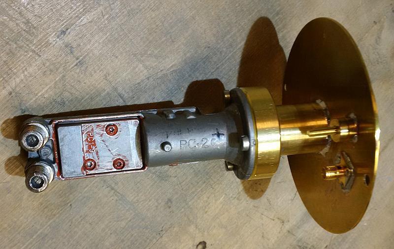
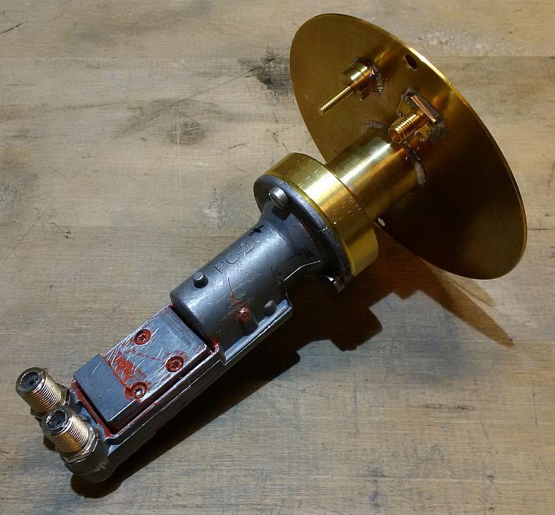
13 13


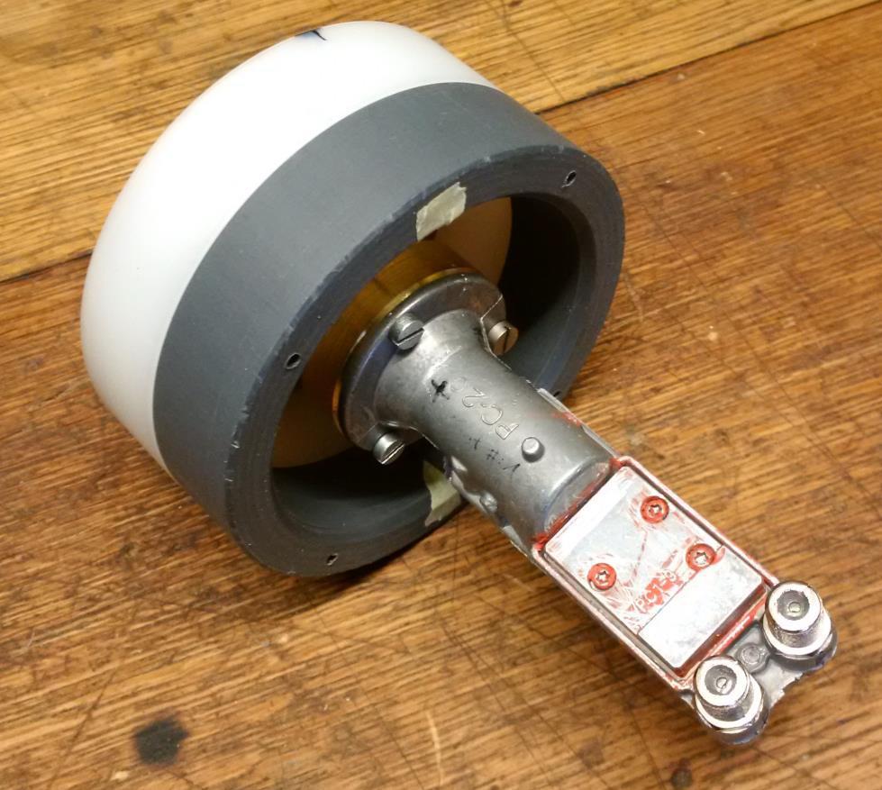
14 The feed is connected to the LNB with a brass adapter, which is soldered to the feed's circular waveguide. The adapter is conical on the inside and provides a tapered transition from the slightly larger inside diameter of the feed to the inside diameter of the LNB. The adapter is bolted to the remaining flange of the LNB. Here's a look from the front into the circular waveguide. 14


15 The feed is held in a plastic tube (with an inner diameter of 100mm) by means of a Teflon ring: 15


16 Here you can see the feed attached to the Teflon ring: 16
17 Next, I measurements the IF output signal with the same measurement setup as it was described before. I compared the output of the modified LNB branch A with the unmodified branch B to see if replacing the quartz with a TCXO did result in any unwanted side effects. Here are the spectra of output A and B measured at a resolution bandwidth of 10 khz and a span of 10 MHz. 17
18 Next, the measurement was repeated with a resolution bandwidth of 300 Hz and a span of 1 MHz: 18
19 In the next measurements, the resolution bandwidth was further reduced to 30 Hz and the span was set to 10 khz. 19
20 Finally, the resolution bandwidth was reduced to 10Hz and the span set to 1kHz. Due to the high drift of the unmodified LNB branch, the measurement was of the first graph was a bit tricky. 20
21 After the modification of branch B of the LNB, the measurements were repeated also for branch B. There was no significant difference to branch A. Therefore, I refrain to represent all traces here. For reference you find next only one of the measured spectra from branch B: Finally, below you will find measurements, which were carried out at the IF output using an Airspy SDR. The measurements were done after the modification of both LNB branches A & B and the final installation of the feed in the weatherproof housing. The horizontal scaling in the graphs is 100 Hz per division. The spectrum as well as the waterfall diagram are in each measurement 1 khz wide. First, output A was measured. A supply voltage of 17 V was used. The input signal was MHz. 21
22 Transient response of the LNB within the first 30 seconds after applying the supply voltage: Here the same measurement after the oscillator has settled: 22
: Next, output B was measured using the same methodology.")
23 In the diagram below, the waterfall chart was taken over a longer time period (in total 12 minutes): Next, output B was measured using the same methodology. 23
24 As you can see the two branches behave almost identically. The only difference is the frequency offset: the LOs (local oscillators) of the two LNB branches differ by 7.9 khz. I would like to point out that during these measurements I did not synchronize neither the SMIQ06 signal generator (with self-made frequency doubler) nor the Airspy SDR with an external reference frequency. The measured frequency drifts are therefore the sum of the entire measurement setup. Furthermore, everything was measured here in the shack at constant ambient temperature. However, since the structure is in a hermetically sealed weatherproof housing and the power dissipation is about 1.8 watts, it can be assumed that the LNB has warmed over time. I am quite satisfied with the results. I have listened to the received signal in CW and it sounds very clean. The remaining drift is about 10 Hz in the short-term range, about 50 Hz over a period of 10 minutes. The drift is obviously continuous which again confirms that the TCXO contains an analogue control loop. Measured over an hour, drift was always below 100Hz. After about 3 hours, the offset was still well below 200Hz. This can be easily compensated for in practical QSO operation, whereby a higher long-term drift is certainly to be expected in outdoor use. When conducting QSOs on EsHail-2 / Qatar-OSCAR 100 with the feed outside, the above measurements were confirmed. The Octagon Dual PLL LNBs with the TCXOs performs very well. 24


25 To protect the feed against the weather I used a 100mm water pipe, on which I glued a bottom plate made of PVC. In this bottom plate the coaxial cable jacks are screwed. The connections are sealed with Spinner Plast2000. So far, I have had very good experiences with this sealing and I intend to seal also the LNB with it when all further tests have been successfully completed. To fix the feed in the tube, another ring of plastic was turned, which was glued into the tube. In this ring M3 threads were cut so that the feed with the Teflon holder is screwed to this ring. Thus, the feed is fixed in the tube and cannot slip neither axially nor radially. 25
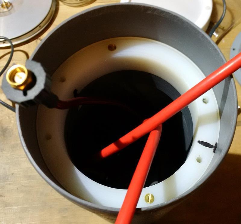
26 26


27 An attachable Teflon cover protects the front of the feed. A Teflon ring holds a thin Teflon foil. A rubber seal is embedded in the Teflon ring. This is the feed after everything was assembled: 27

28 Adjusting the 2.4 GHz patch feed is quite easy with the capacitive probe which can be adjusted with a screw on the back of the patch-feed. The final tuning should be done, when the feed is mounted in the weatherproof housing. Due to the housing and the front cover, the resonance frequency shifts slightly downward. The return loss at 2405 MHz is about 28dB, which corresponds to a VSWR of


29 Finally, here are pictures of the feed mounted in the quick-change bracket of the parabolic dish. 29
30 08:40: :41: :44: :46: :47: :49: :51: :55: :01: :10: :25: :39: :55: :06: :22: :37: :52: :03: :18: :33: :45: :01: :14: :26: :41: :54: :06: :18: :28: :40: :51: :07: :18: :32: :45: :57: :12: :25: :38: :52: Frequency Offset /Hz This setup has proven to work very well on QO-100. With a transmit power of 300mW at the feed my signal is about 30dB above the transponder noise floor. More uplink power is not recommended, in order to avoid triggering the AGC of the satellite. I have been using the LimeSDR-USB with SDR-Radio to operate via QO-100. It works very well. In the latest version Simon has implemented a nice feature which allows SDR-Radio to lock to the PSK beacon of QO-100 and automatically correct the frequency drift of the LNB. In addition, the compensated offset can be recorded in a CSV file. Here are some me measurements I made on March 25 th 2019 from 8:40h to 16:00h. The measurement started exactly when the LNB was first time powered on after being switched off for about 8 hours. As can be seen the LNB started with an offset of 1.3kHz and after about 30 minutes the offset was down to 300Hz. In the next 7 hours the offset varied by about 350 Hz. I would like to reemphasize, that the offset was always compensated by SDR-Radio and this just shows the drift of the modified LNB (i.e. the drift which would have existed if there was no compensation by SDR-Radio). Clearly this drift would have been good enough to operate SSB and CW without having to readjust the frequency frequently. By the way my LimeSDR is locked to a GPSDO, thus we only see the drift of the LNB and not of the whole receiver chain Octagon Dual PLL LNB Frequency Drift Time 30
31 11:10: :20: :29: :36: :43: :49: :00: :08: :15: :21: :30: :37: :43: :51: :59: :05: :13: :19: :24: :30: :36: :43: :49: :58: :06: :13: :19: :26: :35: :41: :48: :55: :04: :12: :20: :26: :34: :42: :49: :56: Frequency Offset /Hz Octagon Dual PLL LNB Frequency Drift Time I am always happy about feedback or question. Please send them preferably by to the address given below. Best regards Matthias DD1US dd1us@amsat.org Homepage: 31
Minimising the tuning drift effects due to external temperature variations in the Titanium Satellite C1W-PLL Wideband LNBF
 Minimising the tuning drift effects due to external temperature variations in the Titanium Satellite C1W-PLL Wideband LNBF Although the Titanium LNB is named in the header, the comments which follow obviously
Es'hail-2 (P4-A), the first geostationary OSCAR from Qatar
, the first geostationary OSCAR from Qatar") Es'hail-2 Es'hail-2 (P4-A), the first geostationary OSCAR from Qatar Presentation Credits: Peter Gülzow, DB2OS AMSAT-DL President, G3VZV and DH2VA Earth Coverage Es'hail-2 AMSAT Payload Block Diagram -
Es'hail-2 Es'hail-2 (P4-A), the first geostationary OSCAR from Qatar Presentation Credits: Peter Gülzow, DB2OS AMSAT-DL President, G3VZV and DH2VA Earth Coverage Es'hail-2 AMSAT Payload Block Diagram -
1Chapter INTRODUCTION. This chapter describes the CST-5000 C-Band satellite terminal, referred to in this manual as the CST-5000 (Figure 1-1).
.") 1Chapter 1. INTRODUCTION This chapter describes the CST-5000 C-Band satellite terminal, referred to in this manual as the CST-5000 (Figure 1-1). Figure 1-1. CST-5000 Single Thread System Rev. 9 1 1 1.1
1Chapter 1. INTRODUCTION This chapter describes the CST-5000 C-Band satellite terminal, referred to in this manual as the CST-5000 (Figure 1-1). Figure 1-1. CST-5000 Single Thread System Rev. 9 1 1 1.1
SDA 3302 Family. GHz PLL with I 2 C Bus and Four Chip Addresses
 GHz PLL with I 2 C Bus and Four Chip Addresses Preliminary Data Features 1-chip system for MPU control (I 2 C bus) 4 programmable chip addresses Short pull-in time for quick channel switch-over and optimized
7000 Series Signal Source Analyzer & Dedicated Phase Noise Test System
 7000 Series Signal Source Analyzer & Dedicated Phase Noise Test System A fully integrated high-performance cross-correlation signal source analyzer with platforms from 5MHz to 7GHz, 26GHz, and 40GHz Key
Model 7330 Signal Source Analyzer Dedicated Phase Noise Test System V1.02
 Model 7330 Signal Source Analyzer Dedicated Phase Noise Test System V1.02 A fully integrated high-performance cross-correlation signal source analyzer from 5 MHz to 33+ GHz Key Features Complete broadband
Software-defined demodulation of Digital Amateur TV from QO-100
 Software-defined demodulation of Digital Amateur TV from QO-100 Copyright 2019 pabr@pabr.org All rights reserved. Since 2019-02-14, licensed amateur radio operators can videoconference via QO-100, the
Titanium Satellite C1W-PLL
 TEST REPORT C band LNBF Titanium Satellite C1W-PLL Cost effective C-band LNBF for satellite enthusiasts Uses PLL technology, which normally could only be found in professional LNBFs Wideband support for
[Q] DRAW TYPICAL CABLE TV NETWORK PLAN AND STATE THE FUNCTION OF DIFFERENT TYPES OF AMPLIFIERS USED IN CABLE TV SYSTEM
![[Q] DRAW TYPICAL CABLE TV NETWORK PLAN AND STATE THE FUNCTION OF DIFFERENT TYPES OF AMPLIFIERS USED IN CABLE TV SYSTEM](/thumbs/74/71403768.jpg "[Q] DRAW TYPICAL CABLE TV NETWORK PLAN AND STATE THE FUNCTION OF DIFFERENT TYPES OF AMPLIFIERS USED IN CABLE TV SYSTEM") 1 Chapter : CABLE TV CONSTRUCTIONAL DETAILS, WORKING AND RADIATION PATTERN OF DISH ANTENNA [Q] DRAW TYPICAL CABLE TV NETWORK PLAN AND STATE THE FUNCTION OF DIFFERENT TYPES OF AMPLIFIERS USED IN CABLE TV
1 Chapter : CABLE TV CONSTRUCTIONAL DETAILS, WORKING AND RADIATION PATTERN OF DISH ANTENNA [Q] DRAW TYPICAL CABLE TV NETWORK PLAN AND STATE THE FUNCTION OF DIFFERENT TYPES OF AMPLIFIERS USED IN CABLE TV
Advanced Test Equipment Rentals ATEC (2832)
") E stablished 1981 Advanced Test Equipment Rentals www.atecorp.com 800-404-ATEC (2832) Technical Datasheet Scalar Network Analyzer Model 8003-10 MHz to 40 GHz The Giga-tronics Model 8003 Precision Scalar
E stablished 1981 Advanced Test Equipment Rentals www.atecorp.com 800-404-ATEC (2832) Technical Datasheet Scalar Network Analyzer Model 8003-10 MHz to 40 GHz The Giga-tronics Model 8003 Precision Scalar
DIY KIT MHZ 8-DIGIT FREQUENCY METER
 This kit is a stand-alone frequency meter capable of measuring repetitive signals up to a frequency of 50MHz. It has two frequency ranges (15 and 50 MHz) as well as two sampling rates (0.1 and 1 second).
CONTENTS GROUND SEGMENT FREQUENCIES MEDIUM-SIZED STATIONS LARGE STATIONS TYPES OF GROUND STATIONS
 CONTENTS GROUND SEGMENT Otto Koudelka Institute of Communication Networks and Satellite Communications Graz University of Technology, Austria koudelka@tugraz.at Types of Ground Stations Architecture Subsystems
Multiple Band Outdoor Block Up- and Downconverters
 Multiple Band Outdoor Block Up- and Downconverters Vertical Mount Option RF IF LO Frequency Frequency Frequency Model Band (GHz) (MHz) (GHz) Number Block Upconverters 1 12.75 13.25 0.95 1.45 11.8 UPB2-WS-13.625
Receiving DATV on four bands with Digital Satellite TV equipment
 Receiving DATV on four bands with Digital Satellite TV equipment By Grant VE3XTV Background: ATV started out on the 70 cm BAND using AM modulation and all contacts were made via simplex. The receivers
Fully ly Automaticti. Motorised Satellite t TV System. User s manual REV
 REV. 1.0 Fully ly Automaticti Motorised Satellite t TV System User s manual Customer Help Line: 1300 139 255 Support Email: support@satkingpromax.com.au Website: www.satkingpromax.com.au www.satkingpromax.com.au
L-Band Block Upconverter MKT-74 Rev B JULY 2017 Page 1 of 7
 Communications & Power Industries Product Description L-Band Block Upconverter (BUC) Introduction The basic architecture of a conventional satcom terminal is derived from the historical desire to keep
DEM 9ULNACK 3.4 GHz. PHEMT LNA amplifier complete kit assembly guide
 DEM 9ULNACK 3.4 GHz. PHEMT LNA amplifier complete kit assembly guide SPECIFICATIONS Noise Figure: < 0.8 db Gain: > 15 db Frequency Range: 3400-3500 MHz Input Voltage: 7-16 VDC Description: The 9ULNACK
Ku-Band Redundant LNB Systems. 1:1 System RF IN (WR75) TEST IN -40 db OFFLINE IN CONTROLLER. 1:2 System POL 1 IN (WR75) TEST IN -40 db POL 2 IN
 TEST IN -40 db OFFLINE IN CONTROLLER. 1:2 System POL 1 IN (WR75) TEST IN -40 db POL 2 IN") BRK-1000 Series Ku-Band Redundant LNB Systems Introduction Redundant LNB systems minimize system downtime due to LNB failure by providing a spare LNB and an automatic means of switching to the spare upon
BRK-1000 Series Ku-Band Redundant LNB Systems Introduction Redundant LNB systems minimize system downtime due to LNB failure by providing a spare LNB and an automatic means of switching to the spare upon
TCXO VCTCXO. Connect Frequency Control TCXO/VCTCXO
 TCXO VCTCXO Connect Control TCXO/VCTCXO TCXO/VCTCXO CTS broad portfolio of Temperature Compensated Crystal Oscillators [TCXOs] and Voltage Controlled Temperature Compensated Crystal Oscillators [VCTCXOs]
INSTRUCTION MANUAL. Model V-4R Collinear Gain Vertical for MHz. General SPECIFICATIONS
 308 Industrial Park Road Starkville, MS 39759 USA, Ph: (662) 323-9538 FAX: (662) 323-651 Model V-4R Collinear Gain Vertical for 420-450 MHz INSTRUCTION MANUAL General The new Hy-Gain V-4R 70cm antenna
Application Note DT-AN DTU-315 Verification of Specifications
 DTU-315 Verification of Specifications APPLICATION NOTE January 2018 Table of Contents 1. Introduction... 3 General Description of the DTU-315... 3 Purpose of this Application Note... 3 2. Measurements...
Modifying the RW1127 and similar TWTs for 24GHz
 Modifying the RW1127 and similar TWTs for 24GHz Some notes by Brian G4NNS updated after the EME conference. Issue 1.04 During a visit from Johannes DF1OI he explained how Ulli DK3UC had modified Siemens
Interactive Satellite Terminal Installation / Validation Manual
 Installation / Validation Manual Version October 5, 2016 Index INTERACTIVE SATELLITE TERMINAL 1. FCC COMPLIANCE... 3 2. TECHNICAL FEATURES...4 3. GENERAL DESCRIPTION...5 4. ELEMENTS CONTAINED IN THE TERMINAL...6
Features. PFD Output Voltage 2000 mv, Pk - Pk. PFD Gain Gain = Vpp / 2π Rad khz 100 MHz Square Wave Ref.
 HMC98LP5 / 98LP5E Typical Applications The HMC98LP5(E) is ideal for: Satellite Communication Systems Point-to-Point Radios Military Applications Sonet Clock Generation Functional Diagram Features Ultra
SPINNER BROADCAST EXPLANATION OF THE MULTI CHANNEL COMBINER SPECIFICATIONS
 EXPLANATION OF THE MULTI CHANNEL COMBINER SPECIFICATIONS Calculation of the maximum permissible output voltage Various signals are added up within the combiner. The peak voltages of the individual signal
SatLabs Recommendation for a Common Inter-Facility Link for DVB-RCS terminals
 SatLabs Recommendation for a Common Inter-Facility Link for DVB-RCS terminals Version 1.6-06/01/2005 This document is the result of a cooperative effort undertaken by the SatLabs Group. Neither the SatLabs
Interactive Satellite Terminal Installation / Validation Manual
 Installation / Validation Manual Version September 14, 2017 Index INTERACTIVE SATELLITE TERMINAL 1. FCC COMPLIANCE... 3 2. TECHNICAL FEATURES...4 3. GENERAL DESCRIPTION...5 4. ELEMENTS CONTAINED IN THE
White Paper. Discone Antenna Design
 White Paper Discone Antenna Design Written by Bill Pretty Highpoint Security Technologies Property of Highpoint Security Technologies Inc The user of this document may use the contents to recreate the
Features. = +25 C, LO = 0 dbm, Vcc = Vcc1, 2, 3 = +5V, G_Bias = +2.5V *
 Typical Applications The is Ideal for: Cellular/3G & LTE/WiMAX/4G Basestations & Repeaters GSM, CDMA & OFDM Transmitters and Receivers Features High Input IP3: +38 dbm 8 db Conversion Loss @ 0 dbm LO Optimized
S op o e p C on o t n rol o s L arni n n i g n g O bj b e j ctiv i e v s
 ET 150 Scope Controls Learning Objectives In this lesson you will: learn the location and function of oscilloscope controls. see block diagrams of analog and digital oscilloscopes. see how different input
ZLNB101 DUAL POLARISATION SWITCH TWIN LNB MULTIPLEX CONTROLLER ISSUE 1- JANUARY 2001 DEVICE DESCRIPTION FEATURES APPLICATIONS
 DUAL POLARISATION SWITCH TWIN LNB MULTIPLEX CONTROLLER ISSUE - JANUARY 00 ZLNB0 DEICE DESCRIPTION The ZLNB0 dual polarisation switch controller is one of a wide range of satellite receiver LNB support
Chapter 6 Tuners. How is a tuner build: In it's most simple form we have an inductor and a capacitor. One in shunt and one in series.
 Chapter 6 Tuners Because most users on the VWNA group are also HAM, I will do some chapters on HAM related gear. But not to worry, a tuner is something you use in most RF designs. A tuner is just a device
Orbital Ka-ISO. Ext Ref Ka LNB with integrated isolator. Orbital Research Ltd Marine Drive, White Rock, BC. Canada V4B 1A9
 Orbital Ka-ISO Ext Ref Ka LNB with integrated isolator Orbital Research Ltd 14239 Marine Drive, White Rock, BC. Canada V4B 1A9 Part number generator Frequencies (GHz): LO Input Output Bandwidth 18.40F
Wideband LNB: 2.4 GHz
 Ka Multi-LO (Preset) Switchable LNB Wideband LNB: 2.4 Orbital Research Ltd 14239 Marine Drive, White Rock, BC. Canada V4B 1A9 Input bandwidth range 2.4 from to Multiple Input and Output ranges switchable
MAXTECH, Inc. BRC-1000 Series. C-Band Redundant LNB Systems. Technology for Communications. System Block Diagrams
 MAXTECH, Inc. Technology for Communications BRC-1000 Series C-Band Redundant LNB Systems Introduction Redundant LNB systems minimize system downtime due to LNB failure by providing a spare LNB and an automatic
USER MANUEL. SNIPE 2 Ref R13
 USER MANUEL SNIPE 2 Ref. 0141317R13 Contents 1. General Information 1-1. Introduction 1-2. Proper use and operation 1-3. Safety notes......... 2 3 3 2. Contents 2-1. Accessory included 2-2. Name of parts......
18 GHz, 2.2 kw KLYSTRON GENERATOR GKP 24KP 18GHz WR62 3x400V
 18 GHz, 2.2 kw KLYSTRON GENERATOR GKP 24KP 18GHz WR62 3x400V With its characteristics of power stability whatever the load, very fast response time when pulsed (via external modulated signal), low ripple,
AT5040 White Paper Final 10/01/12
 Page 1 of 6 AT5040 White Paper Final 10/01/12 AT5040 Studio Vocal Microphone The fundamental operating principles of the condenser microphone are mature, well established technologies that have been the
SingMai Electronics SM06. Advanced Composite Video Interface: HD-SDI to acvi converter module. User Manual. Revision 0.
 SM06 Advanced Composite Video Interface: HD-SDI to acvi converter module User Manual Revision 0.4 1 st May 2017 Page 1 of 26 Revision History Date Revisions Version 17-07-2016 First Draft. 0.1 28-08-2016
SPECIFICATION. Part No. : MA140.A.LB.001
 SPECIFICATION Part No. : MA140.A.LB.001 Product Name : Olympian 2in1 LTE 4G/3G/2G and GPS/GLONASS/GALILEO LTE 698-960/1710-2700MHz 1M RG-316 SMA(M) GPS/GALILEO 1575MHz-Glonass 1602MHz 1M RG-RG-174 SMA(M)
General purpose low noise wideband amplifier for frequencies between DC and 2.2 GHz
 Rev. 5 29 May 2015 Product data sheet 1. Product profile 1.1 General description Silicon Monolitic Microwave Integrated Circuit (MMIC) wideband amplifier with internal matching circuit in a 6-pin SOT363
Modular Block Converter Systems
 Modular Block Converter Systems The Modular Block Converter System eliminates system downtime and maximizes ease of repair by providing fully modular systems for up conversion or down conversion. Critical
USB-TG124A Tracking Generator User Manual
 USB-TG124A Tracking Generator User Manual Signal Hound USB-TG124A User Manual 2017, Signal Hound, Inc. 35707 NE 86th Ave La Center, WA 98629 USA Phone 360.263.5006 Fax 360.263.5007 This information is
FREQUENCY CONVERTER. MULTIPLE OUTPUT WIDEBAND Ku AND Ka DOWNCONVERTERS. Narda-MITEQ FEATURES OPTIONS
 MULTIPLE OUTPUT WIDEBAND Ku AND Ka DOWNCONVERTERS FEATURES Small weather resistant enclosure Automatic 5/10 MHz internal/external reference selection 10/100 Base-T Ethernet and RS-485/RS-422 remote control
Amplifier Systems. 1:1, Dual 1:1 and 1:2 Redundant Low-Noise. Back to
 R Back to Amplifier Systems 1:1, Dual 1:1 and 1:2 Redundant Low-Noise The 1:1, dual 1:1 and 1:2 redundant lownoise amplifier (LNA) systems are designed to ensure continuous operation without disruption
Features. = +25 C, LO = 0 dbm, Vcc = Vcc1, 2, 3 = +5V, G_Bias = +2.5V *
 Typical Applications The is Ideal for: Cellular/3G & LTE/WiMAX/4G Basestations & Repeaters GSM, CDMA & OFDM Transmitters and Receivers Features High Input IP3: +38 dbm 8 db Conversion Loss @ 0 dbm LO Optimized
Specifications. FTS-4335 Series
 Specifications DVB-S2 DUAL NIM Date : 2017. 03. 17. Revision F2 #1501, Halla sigma Valley, 442-2 Sangdaewon-dong, Jungwon-gu, Sungnam City, Gyeonggi-do, Korea, 462-807 Tel. 0755-26504227 Fax. 0755-26505315
a Quick Guide Triax Multi Switches
 a Quick Guide to Triax Multi Switches Satellite reception 1 position 2 positions 4 positions 2 polarities 4 polarities 8 polarities 16 polarities Quick Guide to Triax Multi Switches a sales person s toolbox
General purpose low noise wideband amplifier for frequencies between DC and 2.2 GHz
 Rev. 1 20 October 2011 Product data sheet 1. Product profile 1.1 General description Silicon Monolithic Microwave Integrated Circuit (MMIC) wideband amplifier with internal matching circuit in a 6-pin
Horizon HD-STM. Combo Signal Analyzer TEST REPORT
 TEST REPORT Combo Signal Analyzer Horizon HD-STM can be used intuitively, manual is not needed perfect workmanship optimized for the day-to-day work of an installer gives all the "Must-Have" informations
14 GHz, 2.2 kw KLYSTRON GENERATOR GKP 22KP 14GHz WR62 3x400V
 14 GHz, 2.2 kw KLYSTRON GENERATOR GKP 22KP 14GHz WR62 3x400V With its characteristics of power stability independent of the load, very fast response time when pulsed (via external modulated signal), low
!! 1.0 Technology Brief
 1.0 Technology Brief Table of Contents Contents Scope... 3 Some Satellite Television Principles... 3 Compression... 3... 3 91 Degrees West Longitude... 4 82 Degrees West Longitude... 5 Distribution Technology...
COHERENCE ONE PREAMPLIFIER
 COHERENCE ONE PREAMPLIFIER OWNER S MANUAL TABLE OF CONTENTS Introduction Features Unpacking Instructions Installation Phono Cartridge Loading Basic Troubleshooting Technical Specifications Introduction
Directional Antenna MHz K , SITEL Caponago Tel.02 /
 Directional ntenna 87.5 18 MHz K 52 1 187, 752 119 SITEL Caponago Tel.2 / 95.74.6.9 roadband directional antenna of hot-dip galvanized steel. Especially suitable for square masts. Type No. K 52 1 187 752
EMC-Scanner. HR-series
 EMC-Scanner HR-series Seeing high frequencies! Now you can SEE high frequency electromagnetic fields. Visual noise detection The fact that there is no easy way to find the exact location of a radiating
SC24 Magnetic Field Cancelling System
 SPICER CONSULTING SYSTEM SC24 SC24 Magnetic Field Cancelling System Makes the ambient magnetic field OK for the electron microscope Adapts to field changes within 100 µs Touch screen intelligent user interface
Immunity testing example using Tekbox TEM Cells
 1 Introduction A customer asked us to solve an immunity issue of a corner light. The device failed BCI testing in the test house at frequencies in the 300 MHz to 400 MHz range. The failure mode was flickering
A Huf Puf VFO stabilizer for the YAESU FT-707
 A Huf Puf VFO stabilizer for the YAESU FT-707 Bruno Beckers ON6AB Page 1 The Yaesu FT707 is a good object to add a Huff Puff VFO stabilizer developed by the late Klaas Spaargaren PA0KSB. The version of
Connevans.info. DeafEquipment.co.uk. This product may be purchased from Connevans Limited secure online store at
 Connevans.info Solutions to improve the quality of life Offering you choice Helping you choose This product may be purchased from Connevans Limited secure online store at www.deafequipment.co.uk DeafEquipment.co.uk
Dishes. TDS steel/tda alu. series TDS steel/tda alu. euroline TDS bulk pack DAP series LNB brackets. LNB units
 Dishes - LNB - Switches - Accessories Dishes TDS steel/tda alu. series TDS steel/tda alu. euroline TDS bulk pack DAP series LNB brackets LNB units Universal Single/Twin/Quad Universal Quattro/ Octo Universal
Fully ly Automaticti. Motorised Satellite t TV System. User s manual. ver 3.0.
 ver 3.0 Fully ly Automaticti Motorised Satellite t TV System User s manual Customer Help Line: 1300 139 255 Support Email: support@satkingpromax.com.au Website: www.satkingpromax.com.au www.satkingpromax.com.au
Dish Diversity Switch
 www.travel-vision.com Dish Diversity Switch INSTALLATION & USER S MANUAL Version 3.1 October 2013 PREFACE The information in this Installation and User s Manual is subject to change in order to improve
SC24 Magnetic Field Cancelling System
 SPICER CONSULTING SYSTEM SC24 SC24 Magnetic Field Cancelling System Makes the ambient magnetic field OK for the electron microscope Adapts to field changes within 100 µs Touch screen intelligent user interface
Stereo Box Pre Box Amp Box Amp Box Mono Switch Box. Tuner Box Dock Box F / V Phono Box MM Record Box USB Phono Box II
 Overview Box Program Stereo Box Pre Box Amp Box Amp Box Mono Switch Box Tuner Box Dock Box F / V Phono Box MM Record Box USB Phono Box II Phono Box II USB Phono Box SE II Tube Box II Tube Box SE II Head
X-Band Redundant LNB Systems
 X-Band Redundant LNB Systems BRX-1000 Series Introduction Redundant LNB systems minimize system downtime due to LNB failure by providing a spare LNB and an automatic means of switching to the spare upon
Optimizing BNC PCB Footprint Designs for Digital Video Equipment
 Optimizing BNC PCB Footprint Designs for Digital Video Equipment By Tsun-kit Chin Applications Engineer, Member of Technical Staff National Semiconductor Corp. Introduction An increasing number of video
The Hmc869LC5 is ideal for: Point-to-Point and Point-to-Multi-Point Radio. Parameter Min. Typ. Max. Units
 Typical Applications The Hmc86LC is ideal for: Point-to-Point and Point-to-Multi-Point Radio Military Radar, EW & ELINT Satellite Communications Functional Diagram Features Electrical Specifications, T
TXSYSTEMS. Circuit of a TCG15 AD. Dish Specification 60CM
 TXSYSTEMS TCG15AD Quad Band LNB Gain...60dB Noise Low band....6db Noise High Band...1.2dB Output Frequency...950-2050MHz Switching...N/A Power Consumption... 250mA TCG15 AD Quad 16. 90 Circuit of a TCG15
Data Acquisition Networks. Installing and Configuring the DM01 Hardware
 Data Acquisition Networks Installing and Configuring the DM Hardware What is the DM? D.A.N developed the DM-2 to capture 6 analogue measurements and pulse count in the field. The Average, Maximum and Minimum
INTEGRATED CIRCUITS DATA SHEET. TDA4510 PAL decoder. Product specification File under Integrated Circuits, IC02
 INTEGRATED CIRCUITS DATA SHEET File under Integrated Circuits, IC02 March 1986 GENERAL DESCRIPTION The is a colour decoder for the PAL standard, which is pin sequent compatible with multistandard decoder
HOW TO POINT A DISH ANTENNA
 HOW TO POINT A DISH ANTENNA A2.1 INSTALLING A SATELLITE DISH USING HD RANGER 2 A2.1.1 A bit of history That's it, a bit of history. First artificial satellite "Sputnik I" was launched 4th of October of
Features. = +25 C, IF = 1 GHz, LO = +13 dbm*
 v.5 HMC56LM3 SMT MIXER, 24-4 GHz Typical Applications Features The HMC56LM3 is ideal for: Test Equipment & Sensors Point-to-Point Radios Point-to-Multi-Point Radios Military & Space Functional Diagram
No need for external driver, saving PCB space and cost.
 50Ω 5 to 2700 MHz High Power 3W The Big Deal High Port count in super small size Single Positive Supply Voltage, 2.5 4.8V High Power P0.1dB, 3W typ. Low Insertion Loss, 0.6 db at 1 GHz CASE STYLE: MT1817
1995 Metric CSJ SPECIAL SPECIFICATION ITEM 6031 SINGLE MODE FIBER OPTIC VIDEO TRANSMISSION EQUIPMENT
 1995 Metric CSJ 0508-01-258 SPECIAL SPECIFICATION ITEM 6031 SINGLE MODE FIBER OPTIC VIDEO TRANSMISSION EQUIPMENT 1.0 Description This Item shall govern for the furnishing and installation of color Single
ELLIPTICAL ANTENNA E0851B11
 ELLIPTICAL ANTENNA E0851B11 INSTALLATION GUIDE E0851B11 Installation Manual Step 1: Finding a suitable antenna site A suitable antenna site requires an unobstructed view and a stable antenna mounting surface.
DA : Series of Narrowband or Wideband Distribution Amplifiers
 DA1-100-10: Series of Narrowband or Wideband Distribution Amplifiers Key Features 1-100 MHz wideband Operation. Other band frequencies from 100 khz to 200 MHz are available AGC Level Controlled. Output
MAX2660/MAX2661/MAX2663/MAX2671 Evaluation Kits
 9-382; Rev ; 9/99 MAX2660/MAX266/MAX2663/MAX267 General Description The MAX2660/MAX266/MAX2663/MAX267 evaluation kits simplify evaluation of the MAX2660/MAX266/ MAX2663/MAX267 upconverter s. They enable
SUNSTAR 微波光电 TEL: FAX: v HMC750LP4 / 750LP4E 12.5 Gbps LIMITING AMPLIFIER
 Typical Applications The HMC75LP4(E) is ideal for: OC-192 Receivers Gbps Ethernet Receivers Gbps Fiber Channel Receivers Broadband Test & Measurement Functional Diagram Features Electrical Specifications,
i-repeater Control and monitor all your repeaters through the cloud Rackmount Wallmount
 i-repeater Control and monitor all your repeaters through the cloud Rackmount Wallmount Cloud control and monitoring Touch screen interface Alarms Statisics Details *Device = any repeater or line-amp Connection
12G Broadcast connectors
 12G Broadcast connectors Delivering 12G in a single punch www.coax-connectors.com Welcome to COAX 12G BNC Plug return loss COAX Connectors Ltd is a leading UK designer, manufacturer and supplier of high
SP6T RF Switch JSW6-23DR Ω High Power 3W 5 to 2000 MHz. The Big Deal
 75Ω High Power 3W 5 to 2000 MHz The Big Deal High Port count in super small size High Power P0.1dB, 3W Low Insertion Loss, 0.7 db at 1 GHz CASE STYLE: MT1817 Product Overview is a high power reflective
Features. = +25 C, IF= 100 MHz, LO= +13 dbm* Parameter Min. Typ. Max. Min. Typ. Max. Units
 Features Passive Double Balanced Topology High LO/RF Isolation: 48 db Low Conversion Loss: 7 db Wide IF Bandwidth: DC - GHz Robust 1,000V esd, Class 1C Typical Applications The is ideal for: Point-to-Point
Features. Parameter Min. Typ. Max. Min. Typ. Max. Units
 v. DOWNCONVERTER, - GHz Typical Applications The is ideal for: Point-to-Point and Point-to-Multi-Point Radios Military Radar, EW & ELINT Satellite Communications Maritime & Mobile Radios Features Conversion
Filters for Power Lines (Low Leakage Current)
") Filters for Power Lines (Low Leakage Current) 40 to 100 A, 100 db from 150 khz Series/Type: Date: January 2004 EPCOS AG 2015. Reproduction, publication and dissemination of this publication, enclosures
Filters for Power Lines (Low Leakage Current) 40 to 100 A, 100 db from 150 khz Series/Type: Date: January 2004 EPCOS AG 2015. Reproduction, publication and dissemination of this publication, enclosures
SPECIAL SPECIFICATION 1987 Single Mode Fiber Optic Video Transmission Equipment
 1993 Specifications CSJ 0027-12-086, etc. SPECIAL SPECIFICATION 1987 Single Mode Fiber Optic Video Transmission Equipment 1. Description. This Item shall govern for the furnishing and installation of color
JD725A Cable and Antenna Analyzer - Dual Port
 COMMUNICATIONS TEST & MEASUREMENT SOLUTIONS JD725A Cable and Antenna Analyzer - Dual Port Key Features Portable and lightweight handheld instrument Built-in wireless frequency bands as well as the most
DA MHz Series of Narrowband or Wideband Distribution Amplifiers
 DA1-100-10-10MHz Series of Narrowband or Wideband Distribution Amplifiers Key Features 1-10 MHz wideband Operation. Other band frequencies from 100 khz to 200 MHz are available AGC Level Controlled. Output
Specifications. Dual Satellite Tracking Meter. With a built in 22Khz tone generator. Overview
 Dual Satellite Tracking Meter 38.8 With a built in Khz tone generator Specifications Power demand over 800 ma will result in an Over Current indication. Compatible With STARBAND Receivers Input Frequency:
Bluetooth Tester CBT. Specifications. Specifications. Version January 2006
 Specifications Version 03.00 Bluetooth Tester CBT January 2006 Specifications CONTENTS UNIT SPECIFICATIONS...3 TIMEBASE TCXO...3 REFERENCE FREQUENCY INPUT...3 RF GENERATOR...3 RF ANALYZER...5 Power meter
FM1200RTIM COMTECH TECHNOLOGY CO., LTD. 1. GENERAL SPECIFICATION. 2. STANDARD TEST CONDITION test for electrical specification shall be
 1. GENERAL SPECIFICATION 1-1 Input Frequency Range 1-3 One Input Connector 1-4 Nominal Input Impedance 1-5 Tuning Circuit 1-6 IF Frequency 1-7 IF Bandwidth 1-8 Demodulation 1-9 Video Output Polarity 1-10
DA E: Series of Narrowband or Wideband Distribution Amplifiers
 DA1-150-10-E: Series of Narrowband or Wideband Distribution Amplifiers Key Features Dual A and B inputs. Automatic or manual switchover, configured by the Ethernet port. 1-150 MHz wideband operation. Other
General purpose low noise wideband amplifier for frequencies between DC and 750 MHz
 Rev. 3 13 July 2015 Product data sheet 1. Product profile 1.1 General description Silicon Monolithic Microwave Integrated Circuit (MMIC) wideband amplifier with internal matching circuit in a 6-pin SOT363
High-Value 100 Series (Outdoor)
") R Back to Synthesized/Tunable Converters High-Value 100 Series (Outdoor) HIGH-VALUE OUTDOOR COMMUNICATION CONVERTERS Specifications Outline Drawings Phase Noise System Diagram Control Accessories Options
R Back to Synthesized/Tunable Converters High-Value 100 Series (Outdoor) HIGH-VALUE OUTDOOR COMMUNICATION CONVERTERS Specifications Outline Drawings Phase Noise System Diagram Control Accessories Options
Unicable II Programmable/cascadable multiswitch with 32 User Bands, 4 Universal/Wideband Satellite inputs & 1 Terrestrial input
 Unicable II Programmable/cascadable multiswitch with 32 User Bands, 4 Universal/Wideband Satellite inputs & 1 Terrestrial input (AC/DC power adapter and power inserter) Model: IDLU-UWT110-CUO1O-32P Item:
FREQUENCY CONVERTER HIGH-PERFORMANCE OUTDOOR BLOCK UP AND DOWNCONVERTERS. Narda-MITEQ 1 FEATURES OPTIONS
 FREQUENCY CONVERTER HIGH-PERFORMANCE OUTDOOR BLOCK UP AND DOWNCONVERTERS Standard Configuration Vertical Mount Option FEATURES Antenna mount, weatherproof to IP-65 Automatic 5/10 MHz internal/external
Features. = +25 C, IF= 1 GHz, LO= +13 dbm* Parameter Min. Typ. Max. Units
 Features Passive: No DC Bias Required Input IP3: +2 dbm LO/RF Isolation: 3 db Wide IF Bandwidth: DC - 8 GHz Typical Applications The is ideal for: Telecom Infrastructure Military Radio, Radar & ECM Space
Amateur TV Receiver By Ian F Bennett G6TVJ
 Amateur TV Receiver By Ian F Bennett G6TVJ Here is a design for an ATV receiver which makes use of a Sharp Satellite tuner module. The module was bought from "Satellite Surplus" at a rally a year or so
INTEGRATED ASSEMBLIES MICROWAVE SOLUTIONS FROM TELEDYNE COUGAR
 INTEGRATED ASSEMBLIES MICROWAVE SOLUTIONS FROM TELEDYNE COUGAR INTEGRATED ASSEMBLIES MICROWAVE SOLUTIONS FROM TELEDYNE COUGAR Teledyne Cougar offers full first-level integration capabilities, providing
PSM-2100L Satellite Modem L-Band IF Addendum
 DATUM SYSTEMS PSM-2100L Satellite Modem L-Band IF Addendum 1.0 Introduction Small receive only satellite stations have used L-Band as an outdoor to indoor equipment IF link for several years. The advent
Documentation VFD clock 8 a clock
 Documentation VFD clock 8 a clock This documentation is protected by our copyright. It must not be used for commercial purposes. Congratulations on your purchase of your VFD clock. To guarantee success