USER MANUAL MODEL: VP-792 Warp and Blend Scaler
|
|
|
- Clifton Oscar Mason
- 5 years ago
- Views:
Transcription
1 KRAMER ELECTRONICS LTD. USER MANUAL MODEL: VP-792 Warp and Blend Scaler

2 VP-792 Operating Instructions Version K 1.4
3 This manual explains how to operate your VP-792 warp and blend scaler. VP-792 is designed to provide users with a powerful and flexible method of driving large display devices, and multiple screen applications including flexible geometry correction functions. If you have any queries relating to this or any other product supplied by Kramer visit our Web site For technical support tech@kramerel.com. COPYRIGHT This document and the software described within it are copyrighted with all rights reserved. Under copyright laws, neither the documentation nor the software may be copied, photocopied, reproduced, translated, or reduced to electronic medium or machine readable form, in whole or in part, without prior written consent of Kramer Electronics Ltd ("Kramer"). Failure to comply with this condition may result in prosecution. Kramer does not warrant that this product package will function properly in every hardware and software environment. Although Kramer has tested the hardware, firmware, software and reviewed the documentation, KRAMER MAKES NO WARRANTY OR REPRESENTATION, EITHER EXPRESS OR IMPLIED, WITH RESPECT TO THIS HARDWARE, FIRMWARE, SOFTWARE OR DOCUMENTATION, THEIR QUALITY, PERFORMANCE, MERCHANTABILITY, OR FITNESS FOR A PARTICULAR PURPOSE. THIS SOFTWARE AND DOCUMENTATION ARE LICENSED 'AS IS', AND YOU, THE LICENSEE, BY MAKING USE THEREOF, ARE ASSUMING THE ENTIRE RISK AS TO THEIR QUALITY AND PERFORMANCE. IN NO EVENT WILL KRAMER BE LIABLE FOR DIRECT, INDIRECT, SPECIAL, INCIDENTAL, OR CONSEQUENTIAL DAMAGES ARISING OUT OF THE USE OR INABILITY TO USE THE SOFTWARE OR DOCUMENTATION, even if advised of the possibility of such damages. In particular, and without prejudice to the generality of the foregoing, Kramer has no liability for any programs or data stored or used with Kramer software, including costs of recovering such programs or data. Copyright (c) 2013 All World-wide Rights Reserved All trade marks acknowledged Kramer operates a policy of continued product improvement, therefore specifications are subject to change without notice as products are updated or revised. E&OE.
4 Contents SAFETY WARNING: 1 INTRODUCTION General Introduction Packing List 3 VP-792 SYSTEM DESCRIPTION Product Overview Product Specification Power Supply Requirement Component Video Inputs Computer (SVGA) Inputs VESA formats HDMI & DVI Inputs Display Output 5 VP-792 CONTROL Menu Tree Introduction Main Menu Input Output Output Mode Location Optimize for Display Default Frame Rate DVI Range Frame Rates I/O Lock Native Color Temp Output Gamma Color Black-Level Offset Black-Level Contrast Saturation Hue RGB values Color Temp Input Gamma Geometry Horizontal and Vertical Position Edge Control Warp Picture Format Aspect Ratio Overscan Pan Tilt Zoom Enhancement Sharpness Detail Video Filters System User Names and Profiles Input Config Display Mode Switching Transition Menu Settings Network Settings Factory Defaults Multiple Unit 23
5 Auto Zoom Units Wide and Units High Horizontal Pos and Vertical Pos Blend Width Blend Curve Type 24 REMOTE CONTROL WEB SERVER Introduction Installing the Software Discovery Tool Software Operation File Upload 26 FIRMWARE UPDATE Introduction Updating Firmware 28 ENVIRONMENTAL AND EMC Recommended Operating Conditions Storage CE and FCC Compliance PAT Testing 29
6 SAFETY WARNING: 1. THERE ARE NO USER SERVICEABLE PARTS WITHIN THE UNIT. REMOVAL OF THE TOP COVER WILL EXPOSE DANGEROUS VOLTAGES. DO NOT OPERATE THE UNIT WITHOUT THE TOP COVER INSTALLED. 2. ENSURE THAT ALL ELECTRICAL CONNECTIONS (INCLUDING THE MAINS PLUG AND ANY EXTENSION LEADS) ARE PROPERLY MADE AND COMPLY WITH ELECTRICAL SAFETY REGULATIONS. 3. ENSURE THAT THE INTEGRITY OF THE EQUIPMENT ISOLATION BARRIER IS MAINTAINED WHEN CONNECTING TO OTHER EQUIPMENT. THIS MEANS THAT ONLY LOW VOLTAGE ISOLATED CIRCUITS MAY BE CONNECTED TO THE SIGNAL INPUTS AND OUTPUTS. IF ANY DOUBT EXISTS CONSULT QUALIFIED SERVICE PERSONNEL. 4. TO PREVENT SHOCK OR FIRE HAZARD DO NOT EXPOSE THIS EQUIPMENT TO RAIN OR MOISTURE. IF SUCH EXPOSURE OCCURS, REMOVE THE PLUG FROM THE MAINS OUTLET AND HAVE THE EXPOSED UNIT CHECKED BY QUALIFIED SERVICE PERSONNEL. 5. DO NOT CONTINUE TO OPERATE THE EQUIPMENT IF YOU HAVE ANY DOUBT ABOUT IT WORKING NORMALLY, OR IF IT IS DAMAGED IN ANY WAY. WITHDRAW THE MAINS PLUG FROM THE MAINS OUTLET AND CONSULT QUALIFIED SERVICE PERSONNEL. 6. DO NOT REMOVE ANY FIXED COVERS UNLESS YOU ARE QUALIFIED TO DO SO AND EVEN THEN WITHDRAW THE MAINS PLUG FROM THE MAINS OUTLET BEFORE YOU START. 7. THIS EQUIPMENT CONTAINS NO USER SERVICEABLE PARTS. REFER ALL SERVICING AND MAINTENANCE TO QUALIFIED SERVICE PERSONNEL. 8. TO AVOID EXPLOSION, DO NOT OPERATE THIS EQUIPMENT IN AN EXPLOSIVE ATMOSPHERE
7 1.1. General Introduction INTRODUCTION VP-792 is a very flexible image scaler developed specifically for driving large screen displays and multiple screen applications from video or graphics sources. VP-792 features a state of the art digital image processor which provides market leading HD& SD perpixel multiple Iow-angle motion-adaptive de-interlacing and automatic film pull-down correction for 3:2 and 2:2, significantly outperforming the capabilities of benchmark competitor products. VP-792 features excellent image processing algorithms for the very best scaling, film and video noise reduction and MPEG artefact reduction. VP-792 uses a very flexible high performance video input front end including true component video support in analog YPbPr and RGBS formats. HDMI and DVI video with HDCP encryption is also supported, as are computer graphics inputs in VGA and SVGA analog and HDMI/DVI digital formats. The output format can be set to I/O Lock mode where it locks the output frame rate to the input frame rate dynamically without frame rate conversion so as to reduce system latency, or it can be set to a fixed output frame rate for driving basic screens which are not 50Hz-compatible. Furthermore, the VP-792 can be set to have the output resolution match the input resolution to preserve aspect ratio. A Low latency mode with non-motion adaptive reduced processing is available to further reduce latency. Outputs are available in DVI digital formats. Note that if an HDCP encrypted signal is connected to the HDMI or DVI input, the DVI output signal will be similarly HDCP encrypted. VP-792 supports Pan, Zoom and Tilt to select a part of the input image, fill the screen and pan within it. System control is via an OSD controlled by keys on the front panel or through the inbuilt TCP/IP Web server. Additionally a free API manual is published on our Website at the link given below to allow the use of the LAN or RS232 remote control ports. The VP-792 can be used for multiscreen or multi projector installations featuring Auto Zoom and Edge Blend, as well as embedded warp functions for geometry correction. Edge Blend allows to electronically reduce the brightness level of certain image regions to match the brightness of overlapping areas. Auto Zoom automatically crops and zooms the input video image to display the section of the total image on the corresponding projector or screen. Embedded warp functions allows adjustment of the image in a projection scenario to match a rotated, tilted or curved screen. For 9:16 portrait mode signage special predefined warp maps are available to rotate and stretch a video image to fill a +/-90 rotated display panel. VP-792 also features free form warp capability for non-flat screens in single or multi projector installation. Warp maps created with the PC tool Warp Generator can be uploaded into VP-792. VP-792 is supported by 3 rd party PC based auto calibration software creating such warp maps using camera captured information.
8 1.2. Packing List VP-792 is supplied with the following: 1) This manual 2) 3 pin plug IEC mains cable 3) DVI-D output cable 4) CD containing manuals and useful applications
9 2.1. Product Overview VP-792 SYSTEM DESCRIPTION VP-792 is designed to accept the following input signals: YPbPr or RGBS SD and ED and HD component video via 3 or 4 BNC connectors VGA analog (computer interface) via 15HDD DVI (Digital Visual Interface) via DVI-I (only the digital part is implemented on this connector), HDMI is supported via a HDMI/DVI adapter Product Specification This section provides technical details for all possible inputs. Note that not all possible input options may be applicable to certain output modes Power Supply Requirement 12V DC table top power supply requiring a 100V-264VAC 50 and 60Hz mains connection Component Video Inputs Via 3 or 4 BNC connectors YPbPr, YPbPrS, RGsB and RGBS component video, menu selectable. Signal formats 484i (480i) and 576i (SD), 480p, 576p (ED), 720p, 1080i at 50, and 60Hz and 1080p at 24, 25, and 30Hz. Note this input does not support Computer SVGA signals which should be connected via the Computer SVGA input Computer (SVGA) Inputs VESA formats Signal formats: DOS, VGA WUXGA up to 165MHz pixel clock RGB video level 0.7V - 1.0V RGB input impedance 75 Ohms Sync format Separate H & V sync at TTL 5V levels HDMI & DVI Inputs DVI-D input with or without HDCP HDMI 1.3 with or without HDCP through a DVI/HDMI adapter, 36-bit video compatible. HDCP compatibility can be turned OFF for use with MAC computers. Signal formats -video 484i and 576i (SD) in double-rate formats (1440 pixels per line), 480p, 576p (ED), 720p, 1080i at 50, & 60Hz, 1080p at 24, 25, 30, 50, & 60Hz. Signal formats computer DOS, VGA WUXGA up to 165MHz pixel clock
10 Display Output A DVI-I connector is provided which will support DVI outputs as well as HDMI 1.3 with 36-bit video and HD audio formats when connected to a suitable HDMI 1.3 receiver. When the input signal has HDCP encryption, the DVI-D output connector will carry a similarly HDCP encrypted signal. When an HDCP encrypted signal is input, but the display device does not support HDCP, the output image will turn black and a message indicating HDCP Signal will come up to indicate this.

11 VP-792 CONTROL 3.1. Menu Tree 1 st Level 2 nd Level 3 rd Level 4 th Level
12
13
14
15

16 3.2. Introduction The VP-792 units have the input connectors on one side of the housing and the output connector and communication ports on the opposite side. The keypad for controlling VP-792 is located on the input connectors side. The active input is indicated by their corresponding triangles lit green Keypad with three keys for OSD menu navigation (Menu, Down and Up) and a key for input channel selection (Input). With the Menu key the OSD menu is activated. The up and down keys are used for OSD menu navigation. To exit the OSD menu or any submenu navigate go to the Exit item and press the menu key. To access a submenu navigate to it and press the menu key. To apply a change go to the menu item, press the menu key and make a parameter change with the up and down key. Confirm the change by pressing the Menu key. This will also bring you back to the submenu. By pressing the Input button multiple times the available input channels are toggled through. The active channel is indicated by the associated green lit triangle(s). The exception is that the test patterns are selected through the menu/input With the following multiple key presses further functions can be applied: Keypad unlock: Up and Down Set output and fallback output mode to VGA: Menu and Up Mode reset: Menu and Down Factory reset: Menu and Up and Down
17 A factory reset can also be applied when pressing the factory reset key combination at power up. The keys have to be kept pressed for about 10 seconds until the RGB(S) input LEDs stop flashing. If the keys are released during that 10 seconds period the system will get into Updater mode (see section 5) since the Menu key is part of this key combination. 2 YPbPr and RGB(S) video input 3 DVI-I connector featuring a DVI-D input and a VGA input 4 DVI-I output connector (only the digital DVI-D is supported, HDMI receivers can be connected with a DVI/HDMI adapter cable) 5 TCP/IP port 6 USB port 7 RS232 port 8 Power supply connector
18 3.3. Main Menu The main menu lists the input channel select item, 6 sub menus, and a menu item for automatic setup of VGA modes. The 6 sub menus are Output, Color, Geometry, Enhancement, System and Multiple Unit (only VP-792 and VP-792). On each menu page an Exit menu item is available. The menus are contextual, therefore some adjustments are not applicable to all signal types or operating modes, in which case those non-applicable functions will be ghosted or greyed out and are not accessible. All menus have a top status line and a bottom line indicating the firmware revision number. In the status line the currently selected input channel is indicated and the detected mode is identified. The firmware revision number displays the revision number of the boot-loader behind BL, the revision number of the firmware behind FW and the model 300S, 310, 320 type of the unit. To set up your VP-792 it is recommended that you follow this procedure: Choose the correct output mode and parameters to suit your screen or projector. Select the correct input signal. Set the input levels and features appropriately to optimize the appearance of your image. Set any other parameters to suit your application. Note: All Input parameters are specific to your chosen input channel and input signal type, they are not global to the unit. All Output parameters are global 3.4. Input The list of available inputs can be scrolled through using the Up and Down keys. The new input is not selected until the Menu key is pressed. The list of inputs are: Component, VGA, DVI and Test Pattern. Test patterns can be generated by VP-792 without needing an input connected. When Test Pattern is selected as the input, the required test pattern can be chosen with the menu navigation up and down keys when the menu system has been exited, or it can be selected in Menu>System>Input Config>Test Pattern Setup Output This menu contains adjustments associated with setting up outputs from the unit. Most items are collected in the Display Type submenu. Use the up and down keys to scroll to the required item and press the Menu key Output Mode Settings: 640x480, 800x600, 1024x768, 1280x768, 1280x800, 1280x1024, 1360x768, 1366x768, 1400x1050, 1440x900, 1600x1200, 1680x1050, 1920x1200, 720p (1280x720), 1080p (1920x1080), 480p (720x480), 576p (720x576) Set up the desired output resolution with output mode. The output mode setting should match the native resolution of the imaging device to avoid double scaling. When the system is not in scale but aspect ratio preserve mode which can be set up under the Geometry menu this setting will become the Fallback Output Mode. If the system cannot provide an output resolution to match the input resolution it will use the Fallback Output Mode instead. Also, if there is no input video signal detected the output will be run at this Fallback Output Mode.
19 Location Settings: Front Tabletop, Front Ceiling, Rear Tabletop, Rear Ceiling The image can be flipped to accommodate different projection scenarios as well as screens mounted upside down Optimize for Display Settings: DVI forced, Optimized, DVI/HDMI Internally, the display interface processes data at a full ten bits per color. The color depth on the DVI-D output is determined by the supported standard of the attached monitor or device when set to DVI/HDMI. For DVI 1.0 and HDMI 1.1/1.2 devices it is 24 bit, for HDMI 1.3 compliant devices it is up to 36 bit. DVI forced will output with 24 bit color depth irrespective of the supported standard of the attached monitor. When the Optimized setting is enabled the output resolution is automatically set to the native screen resolution of the attached display by reading the EDID of the display Default Frame Rate Settings: 50Hz, 60Hz, Auto In auto mode the output frame rate follows the input frame rate, when a 50Hz and 60Hz video signal is detected, the output is repeated at 50Hz and 60Hz. When the input video signal has other than 50Hz or 60Hz (with margin) refresh rate, the output is set to 60Hz. Resolution and actual frame rate is shown in the status lines of the OSD window under Output Format DVI Range Settings: Default, Limited, Full When set to Default CEA output modes have limited range, and VESA modes have full range. Therefore, an incoming limited range mode is either passed through when the output is set to a CEA output mode or expanded when the output is set to a VESA mode. An incoming full range mode is either compressed when the output is set to a CEA output mode or passed through when the output is set to a VESA mode. If the HDMI/DVI output does not behave as expected, because the HDMI display is not evaluating AVInfoFrames properly, the range can be changed manually. A limited video range is only using the following greyscale for video information - 8 Bit System: 0x10.. 0xEF, 10 Bit System: 0x x03BF, 12 Bit System: 0x xEFF Frame Rates Available Settings: 60 Hz, 50 Hz, 48 Hz, 24 Hz, Auto In auto mode the output frame rate follows the input frame rate as configured in the Output Config menu. Signals with 24Hz, 25H, 48Hz, 50Hz input modes get special treatment, modes with other refresh rates are displayed at 60Hz. 24Hz input modes will be output at 24Hz if the output resolution is set to either 720p or 1080p and the Frame Rate setting in the Output Config menu includes 24Hz, otherwise it is displayed at twice the rate if the Frame Rate setting in the Output Config menu includes 48Hz. Otherwise a 24Hz input mode is displayed at 60Hz. 48Hz input modes will be output at 48Hz if the Frame Rate setting in the Output Config menu includes 48Hz.
20 Otherwise it is displayed at 50Hz. A 25Hz input mode is output at twice the frame rate 50Hz. An exception to the 24 and 25Hz input mode treatment is if the output resolution is set to 480i or 480p. 480i and 480p are always run at 60Hz output rate. 50Hz input modes are displayed at 50Hz output rate. The output frame rate can also manually set to 24Hz, 48Hz, 50Hz or 60Hz Only 720p and 1080p output modes are available with 24Hz refresh rate. 480i and 480p output modes are only available at 60Hz refresh rate. For all other modes 48Hz, 50Hz and 60Hz refresh rate is available I/O Lock Settings: OFF, Auto If I/O Lock is switched OFF the output is run with a fixed refresh rate determined by the frame rate setting, which deviates from the input refresh rate, even if both are nominally at the same rate. This causes occasional frame dropping or repeat. If I/O Lock is set to Auto the output refresh rate is following the input video refresh rate if locking is possible. Locking is achieved by modulating the output clock and works if input and output refresh rate are nominally at the same rate, when frame rate is set to 60Hz and the video input is also 60Hz. If the video input rate is 50 Hz and the Frame rate is set to 60Hz, the output will enter free run mode. When Frame Rate is set to Auto the matching frame rate is chosen. The status line of the OSD window under Sync Mode indicates if the output signal is locked to the input signal (I/O Locked) or in free run mode (Free Run) Native Color Temp Settings: 5500, 6500, 7500, 9300, Native Color Temp allows the user to select from pre-configured color temperatures to match the display. If both Native Color Temp set here in the Output menu and Color Temp set in the Color menu are set to the same value, no conversion is performed Output Gamma Settings: 1.0 to 3.0 in steps of 0.1 Output gamma allows to re-gamma video signals with pre-configured gamma values to match the display. Input gamma and output gamma both default to 2.2. If they are both set to the same value, there is no effect on the image. Note: If an adjustment to reduce the level of red in the image is required, select a higher number for the (input) Color Temp in the Color menu, or a lower number for the Native Color Temp in the Output menu.
21 3.6. Color This menu contains adjustments associated with setting up inputs to the unit. Use the Up and Down keys to scroll to the required item and press the Menu key Black-Level Offset Available Settings: 0 IRE, 7.5 IRE Used to select 7.5 IRE black level set-up adjustment. Should always be set to 7.5 IRE for HDMI video inputs Black-Level Settings: -50 to 50 in steps of 1 Black level controls the offset applied to the video signal Contrast Settings: -50 to 50 in steps of 1 Contrast controls the gain applied to the video signal Saturation Settings: -50 to 50 in steps of 1 Control of video saturation, applies to all video inputs but not computer input signals or formats Hue Settings: -50 to 50 in steps of 1 Control of video hue, applies to all video inputs but not computer input signals or formats RGB values This is a user-defined color temperature setting whereby individual R,G,B gain and offset (bias) can be set so as to accurately calibrate a particular input to the display device Color Temp Settings: 5500, 6500, 7500, 9300 Color Temp allows the user to select from pre-configured color temperatures to match the color temperature of the incoming signal. If both Color Temp set here in the Color menu and Native Color Temp set in the Output menu are set to the same value, no conversion is performed Input Gamma Settings: Gamma 1.0, Gamma 1.5, Gamma 2.2, Gamma 2.8 Set this value to match the native gamma of the input signal. Input gamma and output gamma both default to 2.2. If they are both set to the same value, there is no effect on the image.
22 3.7. Geometry This menu contains adjustments associated with setting up position, aspect ratio and scale of the input signal. Scale can be as simple as an overscan up to arbitrarily warping the image Horizontal and Vertical Position Settings: in steps of 1 pixel and line Change the positional values to match the display boarders Edge Control Submenu for changing the position of the image edges, effectively scaling the image in horizontal and vertical direction Warp Submenu for warping the image and defining projection condition. The projection condition can be Front Table top, Front Ceiling, Rear Table top or Rear Ceiling. The corresponding image flip is applied on top of the following warp applications. The warp applications are Keystone, 4-Corner, Rotation, and PC. Special portrait warp applications for clockwise (90 ) and counter-clockwise (270 ) rotation with scaling are provided as well. Under the Keystone application the image can be adjusted to match a horizontally and vertically tilted screen. Also, Pin and Barrel distortion of the lens or screen can be adjusted simultaneously. Under the 4-Corner application all corners can be moved and the image is calculated to fit into the given trapezoid. The Rotation application let you rotate the image from -180 to 180 degree (one full circle). At the same time Pin and Barrel distortion of the lens or screen can be adjusted again. Predefined warp maps for portrait mode applications are provided. A 9:16 input image area is rotated and scaled such that is fills a 16:9 screen. With PC application activated the VP-792 communicates with the PC tool Warp Generator. Warp Generator allows you to define an arbitrary screen in live operation by projecting a grid on the surface and move the grid points to get a rectangular output. This grid information can then be downloaded in one of eight slots used for real-time processing of image data which make the image appear rectangular on a curved screen The warp generator software allows rotation, scaling and warping simultaneously.. For convenience all settings can be reset with one button provided in the submenus Picture Format Available Settings: Standard, Full Screen, Crop, Anamorphic Picture Format allows a user to select the displayed aspect ratio where the signal input is at variance with the display panel s natural aspect ratio. Note that some aspect ratios may not be applicable to all signal types, in which case selecting a nonapplicable aspect ratio conversion will have no effect on the displayed image. when a 16:9 image is displayed on a 16:9 panel all settings give an identical full screen image. Standard preserves the aspect ratio of the incoming image and scales the image to fit into the size of the panel. Dependant on the aspect ratio of the panel the image is either bordered by the right and left side or bottom and top of the panel. Non-used areas of the panel are displayed black (letterboxed). Full Screen scales the image to the size of the panel without preservation of the aspect ratio.
23 Crop preserves the aspect ratio and scales the image to fit the screen. Dependant on the aspect ratio of the panel either the top and bottom or right and left areas of the image are cropped. Anamorphic scales the input image such that it is displayed with a 16:9 aspect ratio when displayed on the screen. The image is further scaled to fit into the size of the panel. Dependant on the aspect ratio of the panel the image is then either bordered by the right and left side or bottom and top of the panel. Non-used areas of the panel are displayed black (letterboxed) Aspect Ratio Settings: Scale, Preserve The system can be set to scale the input image to a fixed output resolution or, with the setting preserve, to chose an output resolution matching the input resolution. If no matching output resolution is available or no input is detected, the pre-defined output resolution is used Overscan Settings: 0 to 10 in steps of 1 Overscan is used to slightly zoom into the image when the border area of an image is no longer displayed on the screen. This cuts off unwanted features at the top or bottom Pan Tilt Zoom This menu provides settings to zoom and shrink the image, as well as panning within the image. Pan Tilt Zoom (PTZ) can be switched ON or OFF. Note :- When switching on the latency of the system is increased by one frame. Thus, there is a difference of a PTZ setting OFF or ON with no zoom. Note :- PTZ settings can be saved per mode or globally, if set to global the same PTZ settings are applied when switching input channels or if set to per mode the PTZ setting will only be applied to the input you have selected. The Zoom slider allows to zoom into the image or shrink it. When Aspect Lock is set to ON the separate slider for zooming vertically is greyed out and the horizontal zoom or shrink factor is used as vertical factor as well. The aspect ratio is preserved. When Aspect Lock is OFF horizontal and vertical scaling factors can be chosen separately. With the Pan and Tilt sliders panning within the image in horizontal and vertical direction is possible. Off raster panning is allowed, the image can be shifted outside the active area of the display. For convenience the PTZ settings can be reset with one button.
24 3.8. Enhancement The enhancement menu provides image enhancement functions. Note that the enhancement settings apply to video input signals only, not computer graphics signals Sharpness Available settings: -50 to 50 in steps of 1 Control of the sharpening enhancement filters' levels. These are peaking filters to improve highfrequency response. Note that setting this control too high on a signal which already has good high frequency response will cause ringing or ghosting Detail Available settings: 0, 1, 2, 3 This filter provides powerful 2D image enhancement which can be used to greatly improve detail definition and clarity without causing image ringing or ghosting. It improves both horizontal and vertical detail. Correct setting of the detail enhance filter can make SD signals look virtually indistinguishable from true HD. At setting 0 the filter is switched OFF, with setting 3 providing the highest effect Video Filters The video filters menu provides LTI and CTI filters and TRNR and MNR noise reduction filters. The LTI filter enhances the sharpness of the luminance component. The CTI filter enhances the color sharpness of the chrominance signal by increasing the steepness of color edges. TRNR (Temporal Recursive Noise Reduction) and MNR (Mosquito Noise Reduction) are available for SD input signals only. These filters reduce spatial and temporal noise as well as block artifacts.
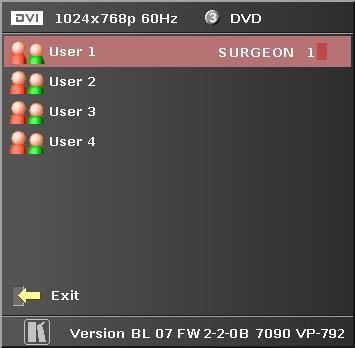
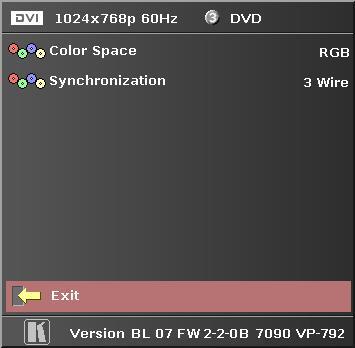
25 3.9. System This selection contains functions which are more applicable to system operation than to picture adjustment User Available settings: USER 1, 2, 3, 4 A predefined setting stored under a user name can be selected. Several settings of the VP-792 can be stored under a user name. Thus, different users can store their preferred VP-792 settings and recall these profiles by picking up their user name from this menu. Note: Using the Web interface, (any number of) settings can also be stored and restored to and from a PC disc drive. This feature is only available on V2 hardware Names and Profiles The Names and Profiles menu provides input masks to rename the generic input channels and user names. User names and input channel names can be changed to any word with a maximum of 12 alpha numeric characters with a value range of 0-9, A-Z and blank. The Names and Profiles menu allows the user to store profiles under a certain user name. It also allows to copy user profiles by loading a profile stored under one user name and saving it under another user name. Reset Profile allows to restore default VP-792 settings for the currently selected user Input Config Inputs can be configured through the following sub-menus: VGA Setup: Submenu for adjusting analog computer video. A button for automatic setup of frequency and phase of the sampling clock is provided. This automatic adjustment is strongly recommended. Frequency (Clock) and phase can also be altered manually. DVI/HDMI Setup: The DVI-I connector may be used to connect a DVI or a HDMI source. A separate connector dedicated to HDMI is not provided because of space limitations. By default the EDID of the box is set to assume a HDMI source supporting video modes accordingly. A DVI source may not behave with the HDMI EDID, in which case the EDID can be changed to support a DVI source more appropriately. The automatic HDMI and DVI Color Space and Range settings can be overwritten in this menu. Range can be set to limited video mode or full range. The DDC can be taken off line. When setting HDCP Input to OFF VP-792 pretends to be non HDCP compliant forcing the source to not encrypt data which is not copy protected. Component Setup: The synchronisation mode can be switched between 3 wire (YPbPr) and 4 wire (RGBS). The color space can be manually switched between YPbPr and RGB. Test Pattern: When the OSD menu is OFF the test pattern can be toggled through by pressing the up or down keys of the keypad. For unit control through a Web browser or to set up a certain default test pattern use the input configuration menu.
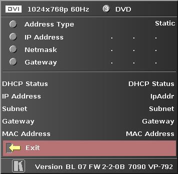
26 Custom test patterns loaded into the file system of the unit through the Web interface, can be accessed through the same means. The speed of the moving cross test pattern can be changed. Also, the foreground and background color and the line width of the moving cross test pattern can be changed in this menu. Note: Most test patterns are scaled in multiple unit configurations with Autozoom enabled since they are useful for setting up the blend and warp of the system. The SMPTE, and Pluge Patterns are not scaled Display Mode The Display Mode can be set to either Low Latency or Best Picture. In Best Picture optimum image processing is applied, whereas in Low Latency mode the lowest latency is achieved. The flicker of interlaced video is not suppressed totally for the latter setting. Thus it has the disadvantage of conventional CRT TVs, but also their advantage of almost no delay in response, which is important for applications such as gaming, simulation or imaging in medical treatment. The latency of the system is ¼ of a frame for progressive input and progressive output when I/O locked. If the output is free running the latency is oscillating between ¼ of a frame and 1 frame. Switching on PTZ adds one frame of latency. Switching on warp adds another frame of latency. If an interlaced video signal is processed in Best Picture mode, this will add one more field of latency. In Low Latency mode this extra field of latency is avoided Switching Transition When switching input channels by default the last frame of the prior displayed image is frozen and displayed until a stable image of the new input channel can be shown. The switchover process is supposed to be as seamless as possible. The source and monitor add switching noise due to unforeseeable activity of the firmware in said devices. By default VP-792 is in auto frame rate switching and I/O lock mode. In these modes the output of the scaler is forced to adopt the sync timings of the input signal In order to get a best smooth switching result between unlocked sources, the source and monitor I/O lock and auto frame rate switching have to be switched OFF in the Output/Display Type menu. This allows the scaler to provide a constant output determined by its own in built clocks Menu Settings This menu provides items to change the menu position and menu display time, the time after which the OSD is switched off again with no user interaction. OSD Messages can be activated and deactivated. The menu language can be altered and the keypad can be locked. To unlock the keypad a combination of keys has to be pressed at the same time. The locking of the keyboard is accompanied by the message: Keypad is locked. Press Up and Down to unlock. When successfully unlocking the keypad the message shows up: Keypad unlocked Network Settings The Network Settings menu allows to configure the VP-792 TCP/IP address for communication with the warp generator PC tool. Under Address Type a static or DHCP leased address can be chosen. The static address and Netmask need to be entered manually. The Network Settings menu has a section with information on the DHCP Status and IP address assigned to the board, as well as the fixed MAC Address programmed into the VP-792. The DHCP status is OFF when static assignment is used or it displays an address when DHCP has leased an address accordingly or it is None assigned if the lease was not successful. Note: When changing from DHCP to Static mode or vice versa it is strongly recommended that VP-792 is powered down after such a change, then powered back up, so that it is properly recognised by other devices on the network.
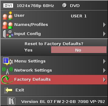
27 In the Network Settings menu is a submenu Status Announce Setting. This feature is activated when Enable Status Announce is switched on. VP-792 will then send messages out continuously through RS232 and TCP/IP to signal system condition. Server address and port of the PC where to send the message need to be entered. The Refresh Rate determines the rate at which the VP-792 status condition and the message entered under Custom Data being sent out Factory Defaults This button let you restore all settings to the default values of the VP-792, thus, provide a means to get back to a known (good) system state. A requestor will come up and ask to confirm prior to actual restore.
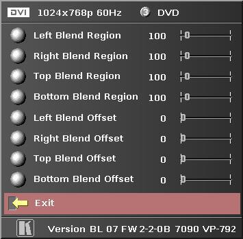
28 3.10. Multiple Unit The VP-792 has a Multiple Unit menu for use in a multi screen application. Multiple screens are stitched together to provide a bigger display with higher resolution than a single display. Each display is driven by a separate VP-792 unit. When using the Auto Zoom function - Each VP-792 unit gets the same graphics or video input signal through a distribution amplifier. The VP-792 unit cuts out and resizes the image to display the part of the image assigned to the corresponding screen. Soft Edge Blending - In a multi projection display the individual projections typically are chosen to overlap to give seamless transitions. Overlapping regions are illuminated by multiple projectors and are brighter than non-overlapping regions. For a uniform brightness over the total display the brightness in the overlapping regions has to be reduced electronically. Important: When using multiple VP-792 units to drive one single large screen, it is essential that all VP- 792 units are I/O locked, otherwise motion tear will be observed at the boundaries of the image processed by each VP-792 unit. It is also essential that all VP-792 units are setup for the same processing latency (either all units are in Best Picture mode or all units are in Low Latency mode) Auto Zoom Available Settings: ON, OFF Auto zoom cuts and resizes the video image to display the assigned part of the total image. Note:- AutoZoom is switched OFF automatically when the on-screen menu cannot be properly displayed. The menu is part of the output and is scaled by the warp engine. There are scenarios when the menu may exceed the size of the screen and also only the active video area can be used for the onscreen menu, this would crop the menu and make it impossible to navigate. A message will indicate such situations. After having made suitable changes the AutoZoom function can be reactivated Units Wide and Units High Available Settings: 1, 2, 3, 4 horizontal and 1, 2, 3, 4 vertical Provides the VP-792 unit with information of the multi screen installation. The number of horizontally and vertically installed screens or projectors is entered Horizontal Pos and Vertical Pos Available Settings: 0 to 3 horizontal and 0 to 3 Vertical Provides the VP-792 unit with the information of which window of the total image it is assigned to. If autozoom is on this tells the unit which part of the image cut out and resize. This selection also determines which edges of the picture are provided with soft edge blends Blend Width The blend width menu provides sliders to set up the overlap region for left, right, top and bottom blend region. When changing the slider value from within the OSD the blend area is not updated live and immediately. An update is forced when pressing the menu/enter button, the slider is replaced by the menu. The overlap is set up in output pixels with a range of up to a third of the output resolution. For a configuration with two projectors in horizontal direction the overlap can be up to two thirds to allow 16:9 images to be made using two combined projectors with an aspect ratio of 4:3 or 5:4. An offset for the blend region can be set-up as well. The region between the edge and the start of the blend area is black.
29 Note: Each VP-792 unit needs to be provided with the exact same value for left and right blend region. Top and bottom blend region have to be identical as well, but don t need to have the same value as left and right. The VP-792 units do not communicate between each other and thus they have to make an assumption for auto zoom calculations and that is overlap of the neighbouring (and those beyond) projectors is identical Blend Curve Type The blend curve type menu allows to set the blending characteristics. For setting up the overlap the Align Pattern should be used. Align Patter reduces the image intensity of each pixel in the blend area by half. When the blend region set up through the blend width menu and the physical blend match the S- Curve characteristics can be switched on. The image intensity is gradually reduced from the start of the blend to the edge of the respective projector image. The S-Curve Value slider allows to control the steepness of the S-Curve. For convenience in this Blend Curve menu a duplicate of the Output Gamma slider can be found to match the grey scale of the images. When a custom alpha map was loaded into the file system of the unit it is recognized at boot time and the Custom Alpha Map menu item becomes available. Custom alpha maps can be uploaded through the Web or remote control API interface of VP-792. The map can be switched ON and OFF. The map is combined with the Align or S-curve map internally generated. If that is not wanted Blend Curve Type has to be set to OFF. The blend map can be warped or left un-warped. Typically, Blend Warping is set to yes at all time. Automatic calibration systems may decide to calculate the blend warp rather than using VP-792 for this purpose. Automatic systems control VP-792 through API calls, in which case the Blend Warping is set automatically and does not need to be touched.

30 4.1. Introduction REMOTE CONTROL WEB SERVER VP-792 features a Web server which connects to a PC Web browser via TCP/IP. The menu system of VP-792 is mirrored into the Web browser and all menu items can be accessed and controlled through the keyboard or mouse of the PC. Note: Backup and Restore is only available for V2 hardware Installing the Software No extra software needs to be installed on a PC. The PC Web browser is used as the graphical user interface for all control items. To connect to the VP-792 the TCP/IP address of the unit has to be entered into the address list box of the Web browser in the following format The TCP/IP address assigned to VP-792 can be found in the System>Network Settings menu Discovery Tool Kramer provides a DiscoveryTool.exe Windows application to identify Kramer boxes in the network. Clicking on the link of the recognized box will open a browser and make a connection to the corresponding box. The box identifier is made up of PV6S in the case of VP-792 followed by the 6 least significant digits of the MAC address. The MAC address of the box can be found in the System>Network Settings menu. Note: This is for use on a network not on a single wire connection.
31 4.4. Software Operation Once the address has been entered the Web browser starts to load pages from the VP-792 mirroring the menu system of the unit. All menu items are shown as their respective buttons, sliders and list boxes and can be accessed and altered with the PC mouse or corresponding navigational key presses. Note:- When changes within a submenu make other menu items available immediately when using the on-screen menu of the VP-792 this has to be either done manually by clicking on the refresh button of the Web browser or is done with the next periodic auto refresh. Values are set by sliders. For fine increment of a slider value click on the slider and use the mouse wheel to change the value in steps of 1. Click again and the value is applied File Upload A page for file uploads is provided. Test patterns can be created and stored on the PC. Four such custom test patterns can be uploaded to and stored by the VP-792 unit. Each of the test patterns in the four slots can be deleted and replaced by another test pattern. The test patterns needs to be in RGB 24bit.PNG format as supported by MS Paint. For best detail the test patterns should be created with the output resolution VP-792 will be operated at. Non matching resolution test patterns will be scaled to the output resolution. A single alpha map can be uploaded to the VP-792 unit. The alpha map format is B/W 16bit.PNG as supported by Adobe Paintshop. Only the most significant 10 bits are used. Also a Kramer proprietary format without compression is supported. This format is intended for uploads in proprietary calibration systems directly controlling the VP-792 unit. Thus a.png encoder does not have to be implemented on the host side. If the alpha map size exceeds the available storage space on the VP-792 unit the.png (lossless compression) has to be used. // Custom Alpha Map File Format // // Offset Size Purpose // 00 4 Header field used to identify custom alpha map file ('AM30') // 04 2 Horizontal resolution in pixels (big endian) // 06 2 Vertical resolution in pixels (big endian) // 08 s Image data // // Each line of image data is built like this: // One 32-bit unsigned (four bytes, big endian) for every three pixels of image data // Bits[31..30] - unused // Bits[20..20] - leftmost pixel of three // Bits[19..10] - middle pixel of three // Bits[09..00] - rightmost pixel of three // Each line has to be zero-padded to make up an integer number of 32-bit unsigned values // // e.g pixels horizontally needs 427 values (1024/3 = , rounded up) // // So the size (s) of the image data is calculated like this: // s = CEILING(ImageWidth /3 ) * 4 * ImageHeight // // Example of a 1920x1200 custom alpha map (all alpha values set to 1): // // D B0 (header)
32 // F FF FF FF 3F FF FF FF (beginning of first line) //... // 000A08 3F FF FF FF 3F FF FF FF (beginning of second line) //... // 2ED608 3F FF FF FF 3F FF FF FF (beginning of last line) // // s = CEILING(1920 /3 ) * 4 * 1200 = bytes
33 5.1. Introduction FIRMWARE UPDATE VP-792 has a USB port which allows a PC connection. With the Kramer PC Updater tool new firmware can be installed on VP-792 for feature upgrades and bug fixes. The latest firmware version for your processor is published on our Website. Save the file to your computer Updating Firmware VP-792 accepts firmware downloads only in a dedicated Updater mode. First disconnect the USB lead. The unit is put in Updater mode by pressing and keeping the Menu key pressed at power up. If the Menu key is released within 10 seconds after power up VP-792 is in Updater mode. Otherwise, VP-792 is started normally. Whilst the Menu key is still pressed the On LED is flashing. When in Updater mode the On LED is flashing two times repeatedly Now the USB connection between PC and VP-792 needs to be established and the Kramer PC Updater tool to be started. The PC Updater tool allows to browse and select a firmware file in BREC format. When a BREC has been selected the Update Firmware button has to be pressed and the firmware download to the VP-792 into non volatile flash RAM starts. After completion of the download VP-792 needs to be restarted normally (without pressing the Menu key) for the change to take effect. It is recommended that a factory reset is now performed.
34 ENVIRONMENTAL AND EMC 6.1. Recommended Operating Conditions Temperature 0 o C to 40 o C Humidity (non condensing) 0% to 95% 6.2. Storage Temperature -25 o C to +85 o C Humidity (non condensing) 0% to 95% 6.3. CE and FCC Compliance CE: This product complies with the requirements of 2004/108/EC Electromagnetic Compatibility Directive, and 2006/95/EC Low Voltage Directive. Compliance is to EN55022 Class A. FCC: WARNING: This equipment has been tested and found to comply with the limits for a Class A digital device pursuant to Part 15 of the FCC Rules. These limits are designed to provide reasonable protection against harmful interference when the equipment is operated in a commercial environment. This equipment generates uses and can radiate radio frequency energy and, if not installed and used in accordance with the instruction manual, may cause interference to radio communications. Operation of this equipment in a residential area is likely to cause interference in which case the user will be required to correct the interference at their own expense. The user is cautioned that changes and modifications made to the equipment without approval of the manufacturer could void the user s authority to operate this equipment. It is suggested that the user use only shielded and grounded signal cables to ensure compliance with FCC rules PAT Testing Earth continuity testing under PAT regulations shall be done to the VP-792 with 8A or 10A only. A test with 25A may damage the unit. In fact, VP-792 is IT equipment and the IEE Code of Practise to check earth continuity suggests an alternative mA test. If the PAT tester does not provide this method and a high current test is to be used instead a 8A or 10A test will be acceptable under the same IEE Code of Practise (a minimum of 1.5 times of the VP-792 internal 5A fuse). You have to be careful where you connect the earth bond test lead when using 8A or 10A. It is to the metal chassis that you must connect the test lead (mains earth). DO NOT CONNECT to the connectors of the rear panel (signal earth). The VP-792 may never work again.
35 For the latest information on our products and a list of Kramer distributors, visit our Web site where updates to this user manual may be found. We welcome your questions, comments, and feedback. Web site: info@kramerel.com! SAFETY WARNING Disconnect the unit from the power supply before opening and servicing
USER MANUAL MODEL: VP-793 Warp-Blend
 KRAMER ELECTRONICS LTD. USER MANUAL MODEL: VP-793 Warp-Blend VP-793 Operating Instructions Version K1.3 This manual explains how to operate your VP-793 warp-blend scaler. VP-793 is designed to provide
HQView-325 Operating Instructions
 HQView-325 Operating Instructions This manual explains how to operate your HQView-325 image scaler. HQView-325 is designed to provide users with a powerful and flexible method of driving large display
OPERATING GUIDE. HIGHlite 660 series. High Brightness Digital Video Projector 16:9 widescreen display. Rev A June A
 OPERATING GUIDE HIGHlite 660 series High Brightness Digital Video Projector 16:9 widescreen display 111-9714A Digital Projection HIGHlite 660 series CONTENTS Operating Guide CONTENTS About this Guide...
LEDView510 and LEDView530 Operating Instructions
 LEDView510 and LEDView530 Operating Instructions Version 2.20 IMPORTANT NOTICE: When using extreme shrink to drive a single or few LED modules the OSD menu of LEDView may become hardly readable - including
HQView-500 Series Operating Instructions
 HQView-500 Series Operating Instructions Version 2.40 This manual explains how to operate your HQView-500 Series (HQView-5xx) image scaler. The HQView-500 Series comes in four versions HQView-500S, HQView-510,
USER MANUAL. VP-435 Component / UXGA HDMI Scaler MODEL: P/N: Rev 13
 KRAMER ELECTRONICS LTD. USER MANUAL MODEL: VP-435 Component / UXGA HDMI Scaler P/N: 2900-000262 Rev 13 Contents 1 Introduction 1 2 Getting Started 2 2.1 Achieving the Best Performance 2 2.2 Safety Instructions
G-106Ex Single channel edge blending Processor. G-106Ex is multiple purpose video processor with warp, de-warp, video wall control, format
 G-106Ex Single channel edge blending Processor G-106Ex is multiple purpose video processor with warp, de-warp, video wall control, format conversion, scaler switcher, PIP/POP, 3D format conversion, image
USER MANUAL. VP-426 HDMI-PC Scaler MODEL: P/N: Rev 4.
 USER MANUAL MODEL: VP-426 HDMI-PC Scaler P/N: 2900-300277 Rev 4 www.kramerav.com Contents 1 Introduction 1 2 Getting Started 2 2.1 Achieving the Best Performance 2 2.2 Safety Instructions 2 2.3 Recycling
G-106 GWarp Processor. G-106 is multiple purpose video processor with warp, de-warp, video wall control, format conversion,
 G-106 GWarp Processor G-106 is multiple purpose video processor with warp, de-warp, video wall control, format conversion, scaler switcher, PIP/POP, 3D format conversion, image cropping and flip/rotation.
USER MANUAL. VP-425 PC / Component to HDMI Scaler MODEL: P/N: Rev 3
 KRAMER ELECTRONICS LTD. USER MANUAL MODEL: VP-425 PC / Component to HDMI Scaler P/N: 2900-300111 Rev 3 Contents 1 Introduction 1 2 Getting Started 2 2.1 Achieving the Best Performance 2 2.2 Safety Instructions
USER MANUAL. VP-424 HDMI to HDMI Scaler MODEL: P/N: Rev 2
 KRAMER ELECTRONICS LTD. USER MANUAL MODEL: VP-424 HDMI to HDMI Scaler P/N: 2900-000765 Rev 2 Contents 1 Introduction 1 2 Getting Started 2 2.1 Achieving the Best Performance 2 2.2 Safety Instructions
User Manual. PC / HD Scaler. with advanced video processing. VGA to Component Video Component Video to VGA VGA to VGA Component to Component
 User Manual PC / HD Scaler with advanced video processing VGA to Component Video Component Video to VGA VGA to VGA Component to Component Model 1366 WARNINGS Read these instructions before installing or
KRAMER ELECTRONICS LTD. USER MANUAL
 KRAMER ELECTRONICS LTD. USER MANUAL MODEL: Projection Curved Screen Blend Guide How to blend projection images on a curved screen using the Warp Generator version K-1.4 Introduction The guide describes
The absolute opposite of ordinary. G804 Quad Channel Edge Blending processor
 The absolute opposite of ordinary G804 Quad Channel Edge Blending processor Input: up to 4096*2160 @60hz 4:4:4 full color sampling Output: 2048*1080 @60Hz New generation Warp & Edge blending engine Technical
USER MANUAL. 22" Class Slim HD Widescreen Monitor L215DS
 USER MANUAL 22" Class Slim HD Widescreen Monitor L215DS TABLE OF CONTENTS 1 Getting Started Package Includes Installation 2 Control Panel / Back Panel Control Panel Back Panel 3 On Screen Display 4 Technical
USER MANUAL. VP-501N UXGA Scan Converter MODEL: P/N: Rev 5
 KRAMER ELECTRONICS LTD. USER MANUAL MODEL: VP-501N UXGA Scan Converter P/N: 2900-300183 Rev 5 Contents 1 Introduction 1 2 Getting Started 2 2.1 Achieving the Best Performance 2 2.2 Safety Instructions
USER MANUAL. VP-427 HDBaseT to HDMI Receiver/Scaler MODEL: P/N: Rev 5
 KRAMER ELECTRONICS LTD. USER MANUAL MODEL: VP-427 HDBaseT to HDMI Receiver/Scaler P/N: 2900-300328 Rev 5 Contents 1 Introduction 1 2 Getting Started 2 2.1 Achieving the Best Performance 2 2.2 Safety Instructions
USER MANUAL. 27 Full HD Widescreen LED Monitor L27ADS
 USER MANUAL 27 Full HD Widescreen LED Monitor L27ADS TABLE OF CONTENTS 1 Getting Started 2 Control Panel/ Back Panel 3 On Screen Display 4 Technical Specs 5 Care & Maintenance 6 Troubleshooting 7 Safety
CP-255ID Multi-Format to DVI Scaler
 CP-255ID Multi-Format to DVI Scaler Operation Manual DISCLAIMERS The information in this manual has been carefully checked and is believed to be accurate. Cypress Technology assumes no responsibility
DVI/PC/HD to DVI/PC Scaler - ID# 15320
 DVI/PC/HD to DVI/PC Scaler - ID# 15320 Operation Manual Introduction This DVI/PC/HD to DVI/PC Scaler is capable of scaling and sourceswitching from PC (VGA), Component Video (SD/HD) and DVI input signals
2D/3D Multi-Projector Stacking Processor. User Manual AF5D-21
 2D/3D Multi-Projector Stacking Processor User Manual AF5D-21 Thank you for choosing AF5D-21 passive 3D processor. AF5D-21 is an advanced dual channel passive 3D processor with 10 bits high end scaler and
SUPERSCALE Multi-Format to HDMI Scaler
 SUPERSCALE Multi-Format to HDMI Scaler Operation Manual DISCLAIMERS The information in this manual has been carefully checked and is believed to be accurate. SPATZ assumes no responsibility for any infringements
G406 application note for projector
 G406 application note for projector Do you have trouble in using projector internal warp and edge blending function? Inconvenient in multiple signal source connection System resolution is not enough after
USER MANUAL. HIGHlite Laser 3D Series INSTALLATION AND QUICK-START GUIDE CONNECTION GUIDE OPERATING GUIDE REMOTE COMMUNICATIONS GUIDE REFERENCE GUIDE
 HIGHlite Laser 3D Series High Brightness Digital Video Projector USER MANUAL INSTALLATION AND QUICK-START GUIDE CONNECTION GUIDE OPERATING GUIDE REMOTE COMMUNICATIONS GUIDE REFERENCE GUIDE 114-913A Digital
OPERATING GUIDE. M-Vision Cine 3D series. High Brightness Digital Video Projector 16:9 widescreen display. Rev A August A
 OPERATING GUIDE M-Vision Cine 3D series High Brightness Digital Video Projector 16:9 widescreen display 112-022A Digital Projection M-Vision Cine 3D series CONTENTS Operating Guide CONTENTS About this
USER MANUAL. VP-422 HDMI to PC Scaler MODEL: P/N: Rev 5
 KRAMER ELECTRONICS LTD. USER MANUAL MODEL: VP-422 HDMI to PC Scaler P/N: 2900-000580 Rev 5 Contents 1 Introduction 1 2 Getting Started 2 2.1 Achieving the Best Performance 2 2.2 Safety Instructions 3
USER MANUAL. 27 Full HD Widescreen LED Monitor L270E
 USER MANUAL 27 Full HD Widescreen LED Monitor L270E TABLE OF CONTENTS 1 Getting Started 2 Control Panel/ Back Panel 3 On Screen Display 4 Technical Specs 5 Care & Maintenance 6 Troubleshooting 7 Safety
17 19 PROFESSIONAL LCD COLOUR MONITOR ART
 17 19 PROFESSIONAL LCD COLOUR MONITOR ART. 41657-41659 Via Don Arrigoni, 5 24020 Rovetta S. Lorenzo (Bergamo) http://www.comelit.eu e-mail:export.department@comelit.it WARNING: TO REDUCE THE RISK OF FIRE
PC/HDTV 2-Way Converter
 Vision for Net Media HDView PC/HDTV 2-Way Converter Operation Manual 1. Introduction The HDView is a high-performance universal PC/HDTV to PC/HDTV converter. It combines the functions of a video scaler,
Kramer Electronics, Ltd. USER MANUAL. Models: VP-715, Video To SXGA / HD Scaler VP-716, Video To SXGA / DVI / HD Scaler
 Kramer Electronics, Ltd. USER MANUAL Models: VP-715, Video To SXGA / HD Scaler VP-716, Video To SXGA / DVI / HD Scaler Contents Contents 1 Introduction 1 2 Getting Started 1 3 Overview 1 3.1 VP-715/6 Scaler
User Manual MODEL: KK1500-TR. Touch Display LCD Monitor. Installation Guide. 15 Resistive Touch LCD Monitor
 Touch Display LCD Monitor User Manual Installation Guide 15 Resistive Touch LCD Monitor MODEL: KK1500-TR i-tech Company LLC TOLL FREE: (888) 483-2418 EMAIL: info@itechlcd.com WEB: www.itechlcd.com User
User Manual MODEL: KKF1500-PCAP. True FLAT P-CAP LCD Monitor. Installation Guide. 15 True FLAT P-CAP Touch LCD Monitor
 True FLAT P-CAP LCD Monitor User Manual Installation Guide 15 True FLAT P-CAP Touch LCD Monitor MODEL: KKF1500-PCAP i-tech Company LLC TOLL FREE: (888) 483-2418 EMAIL: info@itechlcd.com WEB: www.itechlcd.com
CSLUX-300 Multi-Format to HDMI Scaler
 CSLUX-300 Multi-Format to HDMI Scaler Operation Manual DISCLAIMERS The information in this manual has been carefully checked and is believed to be accurate. Cypress Technology assumes no responsibility
4K Presentation switcher-scaler Chameleon PS200/300 series 2017
 4K Presentation switcher-scaler Chameleon PS200/300 series 2017 Chameleon PS200/300 series HQUltra technology was chosen by the European Broadcast Union for frame rate and standards conversion of the recent
PRO-ScalerHD2V HDMI to VGA & Audio Scaler Converter. User s Guide. Made in Taiwan
 PRO-ScalerHD2V HDMI to VGA & Audio Scaler Converter User s Guide Made in Taiwan Congratulations for owning a gofanco product. Our products aim to meet all your connectivity needs wherever you go. Have
USER MANUAL Full HD Widescreen LED Monitor L215ADS
 USER MANUAL 21.5 Full HD Widescreen LED Monitor L215ADS TABLE OF CONTENTS 1 Getting Started 2 Control Panel/ Back Panel 3 On Screen Display 4 Technical Specs 5 Care & Maintenance 6 Troubleshooting 7 Safety
USER MANUAL Full HD Widescreen LED Monitor L215IPS
 USER MANUAL 21.5 Full HD Widescreen LED Monitor L215IPS TABLE OF CONTENTS 1 Getting Started 2 Control Panel/ Back Panel 3 On Screen Display 4 Technical Specs 5 Care & Maintenance 6 Troubleshooting 7 Safety
Introduction...2. Features...2 Safety Precautions...2. Installation...4
 PE1900 Contents Introduction...2 Features...2 Safety Precautions...2 Installation...4 Unpacking the Display...4 Locations and Functions of Controls...4 Connections...5 Using Your Display...7 Turning the
RHP-IS DESKTOP IMAGE STABILIZER
 RHP-IS DESKTOP IMAGE STABILIZER Instruction Manual Firmware release 2.1 and above 2005-06-22 Rock2000.com P.O. BOX 4242, Middletown, New York, 10941, USA www.rock2000.com support@rock2000.com 2 Contents
SC-CSV-HDMI Composite & S-Video To HDMI Video Processor
 SC-CSV-HDMI Composite & S-Video To HDMI Video Processor UMA1173 Rev. NC CUSTOMER SUPPORT INFORMATION Order toll-free in the U.S. 800-959-6439 FREE technical support, Call 714-641-6607 or fax 714-641-6698
G-700LITELite multiple Channel warping processor
 G-700LITELite multiple Channel warping processor Version: 2.01, Date: 2017-07 G-700Lite is a warping processor with the ability to provide multiple processing modules to control from 1 to 4 projectors
SC-HD-2A HDMI Scaler & Audio Embedder / Extractor
 User s Manual SC-HD-2A HDMI Scaler & Audio Embedder / Extractor Scale HDMI or DVI video Embed Digital or Analog Audio into HDMI output Extract (De-embed) Digital and Analog Audio from HDMI input UMA1246
User Manual. Model 1365 Video Scaler
 User Manual Model 1365 Video Scaler Model 1365 PC/HD Video Converter Table Of Contents 1.0 Introduction........................3 2.0 Specifications....................... 4 3.0 Checking Package Contents................5
Video Converter & Scaler
 Video Converter & Scaler VGA or Composite Video to DVI-I Output Converter and Scaler VGA2DVII Instruction Manual Actual product may vary from photo FCC Compliance Statement This equipment has been tested
PLL2210MW LED Monitor
 PLL2210MW LED Monitor USER'S GUIDE www.planar.com Content Operation Instructions...1 Safety Precautions...2 First Setup...3 Front View of the Product...4 Rear View of the Product...5 Quick Installation...6
USER MANUAL. HIGHlite Laser 3D Series INSTALLATION AND QUICK-START GUIDE CONNECTION GUIDE OPERATING GUIDE REFERENCE GUIDE
 HIGHlite Laser 3D Series High Brightness Digital Video Projector USER MANUAL INSTALLATION AND QUICK-START GUIDE CONNECTION GUIDE OPERATING GUIDE REFERENCE GUIDE 114-913B Digital Projection HIGHlite Laser
DVI Digital scaler with ultra high bandwidth ID#442
 DVI Digital scaler with ultra high bandwidth ID#442 Operation Manual Introduction Congratulations on your purchase of the DVI Digital scaler with ultra high bandwidth. Please read this to become familiar
DISTRIBUTION AMPLIFIER
 MANUAL PART NUMBER: 400-0045-005 DA1907SX 1-IN, 2-OUT VGA/SVGA/XGA/UXGA DISTRIBUTION AMPLIFIER USER S GUIDE TABLE OF CONTENTS Page PRECAUTIONS / SAFETY WARNINGS... 2 GENERAL...2 GUIDELINES FOR RACK-MOUNTING...2
USER MANUAL Full HD Widescreen LED Monitor L236VA
 USER MANUAL 23.6 Full HD Widescreen LED Monitor L236VA TABLE OF CONTENTS 1 Getting Started 2 Control Panel/ Back Panel 3 On Screen Display 4 Technical Specs 5 Care & Maintenance 6 Troubleshooting 7 Safety
DC162 Digital Visualizer. User Manual. English - 1
 DC162 Digital Visualizer User Manual English - 1 Table of Contents CHAPTER 1 PRECAUTIONS... 5 CHAPTER 2 PACKAGE CONTENT... 7 CHAPTER 3 PRODUCT OVERVIEW... 8 3.1 PRODUCT INTRODUCTION... 8 3.2 I/O CONNECTION...
USER MANUAL. 28" 4K Ultra HD Monitor L28TN4K
 USER MANUAL 28" 4K Ultra HD Monitor L28TN4K TABLE OF CONTENTS 1 Getting Started 2 Control Panel/ Back Panel 3 On Screen Display 4 Technical Specs 5 Care & Maintenance 6 Troubleshooting 7 Safety Info &
ivw-fd122 Video Wall Controller MODEL: ivw-fd122 Video Wall Controller Supports 2 x 2 Video Wall Array User Manual Page i Rev. 1.
 MODEL: ivw-fd122 Video Wall Controller Supports 2 x 2 Video Wall Array User Manual Rev. 1.01 Page i Copyright COPYRIGHT NOTICE The information in this document is subject to change without prior notice
USER MANUAL. VP-427A HDBaseT to HDMI+Audio Receiver/Scaler MODEL: P/N: Rev 1
 KRAMER ELECTRONICS LTD. USER MANUAL MODEL: VP-427A HDBaseT to HDMI+Audio Receiver/Scaler P/N: 2900-300425 Rev 1 Contents 1 Introduction 1 2 Getting Started 2 2.1 Achieving the Best Performance 2 2.2 Safety
SK2002DA SIDEKICKER 1-IN, 2-OUT VGA-UXGA DISTRIBUTION AMPLIFIER CABLE USER S GUIDE DISTRIBUTION AMPLIFIERS
 MANUAL PART NUMBER: 400-0152-001 PRODUCT REVISION: 0 SK2002DA SIDEKICKER 1-IN, 2-OUT VGA-UXGA DISTRIBUTION AMPLIFIER CABLE USER S GUIDE TABLE OF CONTENTS Page PRECAUTIONS / SAFETY WARNINGS...2 GENERAL...2
LEDView530 Operating Instructions
 LEDView530 Operating Instructions Version 2.46 IMPORTANT NOTICE: When using extreme shrink to drive a single or few LED modules the OSD menu of LEDView may become hardly readable - including the assigned
User Manual TL-2X1-HDVC 2x1 HDMI & VGA Switcher with Control All Rights Reserved Version: TL-2X1-HDVC_160630
 User Manual TL-2X1-HDVC 2x1 HDMI & VGA Switcher with Control All Rights Reserved Version: TL-2X1-HDVC_160630 Preface Read this user manual carefully before using this product. Pictures shown in this manual
CSLUX-300I Multi-Format to HDMI Scaler
 CSLUX-300I Multi-Format to HDMI Scaler Operation Manual DISCLAIMERS The information in this manual has been carefully checked and is believed to be accurate. Cypress Technology assumes no responsibility
Instruction Guide. Component/Composite/S-Video to DVI-D/HDTV Scaler and Converter Component/Composite/S-Video to VGA/HDTV Scaler and Converter
 VIDEO SCALER Component/Composite/S-Video to DVI-D/HDTV Scaler and Converter Component/Composite/S-Video to VGA/HDTV Scaler and Converter VID2DVIDTV (DVI) VID2VGATV (VGA) Instruction Guide * Actual product
Model Extend HDMI audio and video connections up to 300 feet. Add up to 8 additional receivers with a dedicated network switch
 HDMI Extender over Single CAT 6 Cable with IR Control Model 103002 Extend HDMI audio and video connections up to 300 feet Utilize existing Cat 6 wiring for an easy installation Add up to 8 additional receivers
LCD VALUE SERIES (32 inches)
") LCD VALUE SERIES (32 inches) http://www.orionimages.com All contents of this document may change without prior notice, and actual product appearance may differ from that depicted herein 1. SAFETY INSTRUCTION
LCD VALUE SERIES (32 inches) http://www.orionimages.com All contents of this document may change without prior notice, and actual product appearance may differ from that depicted herein 1. SAFETY INSTRUCTION
USER MANUAL. KW-11T Wireless High Definition Transmitter. KW-11R Wireless High Definition Receiver MODELS: P/N: Rev 9
 KRAMER ELECTRONICS LTD. USER MANUAL MODELS: KW-11T Wireless High Definition Transmitter KW-11R Wireless High Definition Receiver P/N: 2900-300194 Rev 9 Contents 1 Introduction 1 2 Getting Started 2 2.1
YCbCr (480i/576i) and RGBsync. 4 Press Component to change source to component connec tor. This connector supports YPbPr (480p/576p/720p/1080i)
 and RGBsync. 4 Press Component to change source to component connec tor. This connector supports YPbPr (480p/576p/720p/1080i)") Introduction Product Features This product is an XGA single chip 0.7 DLP TM projector. Outstanding features include: u True XGA, 1024 x 768 addressable pixels u Single chip DLP TM technology u NTSC3.58/NTSC4.43/PAL/SECAM
Introduction Product Features This product is an XGA single chip 0.7 DLP TM projector. Outstanding features include: u True XGA, 1024 x 768 addressable pixels u Single chip DLP TM technology u NTSC3.58/NTSC4.43/PAL/SECAM
Camera 220C Document Camera User s Guide
 Camera 220C Document Camera User s Guide #401-220C-00 Table of Contents TABLE OF CONTENTS... 0 TABLE OF CONTENTS... 1 COPYRIGHT INFORMATION... 2 CHAPTER 1 PRECAUTIONS... 3 CHAPTER 2 PACKAGE CONTENT...
User Manual rev: Made in Taiwan
 CV-500S HDMI to Component/CVBS & Audio Scaler Converter User Manual rev: 131218 Made in Taiwan The CV-500S HDMI to Component/CVBS & Audio Scaler Converter has been tested for conformance to safety regulations
HIGHlite Laser 3D Series High Brightness Digital Video Projector
 HIGHlite Laser 3D Series High Brightness Digital Video Projector 4INSTALLATION AND QUICK-START GUIDE 4CONNECTION GUIDE 4OPERATING GUIDE 4REFERENCE GUIDE 114-913C About This Document Follow the instructions
TFT LCD MONITOR USER MANUAL. L80AP and L101AP
 TFT LCD MONITOR USER MANUAL L80AP - 8.0 and L101AP - 10.1 Table Of Contents Table of contents/ Warning.... 2 Precautions...3 About this user manual and products / Items included in the delivery..... 4
High-Definition Scaler. GTV-HIDEFS. User Manual
 High-Definition Scaler GTV-HIDEFS User Manual www.gefentv.com Technical Support: Telephone (818) 772-9100 (800) 545-6900 Fax (818) 772-9120 Technical Support Hours: 8:00 AM to 5:00 PM Monday thru Friday.
It will cause malfunction if the monitor is operating with unspecified power supply
 User Manual / Installation Guide Model No. PTM-1525R/RT Warning! It will cause malfunction if the monitor is operating with unspecified power supply unit or incorrect power voltage. Do not exposure this
HD Mate Scaler USER MANUAL.
 HD Mate Scaler USER MANUAL www.gefen.com ASKING FOR ASSISTANCE Technical Support: Telephone (818) 772-9100 (800) 545-6900 Fax (818) 772-9120 Technical Support Hours: 8:00 AM to 5:00 PM Monday through Friday
DA IN 1-OUT LINE DRIVER WITH EQUALIZATION + AUDIO USER S GUIDE
 MANUAL PART NUMBER: 400-0430-001 1-IN 1-OUT LINE DRIVER WITH UALIZATION + AUDIO USER S GUIDE TABLE OF CONTENTS Page PRECAUTIONS / SAFETY WARNINGS... 2 GENERAL...2 GUIDELINES FOR RACK-MOUNTING...2 INSTALLATION...2
PremierViewProHD-LED Operating Instructions
 PremierViewProHD-LED Operating Instructions This manual explains how to operate your PremierViewProHD-LED (PVProHD-LED) image scaler. The PVProHD-LED is designed to provide users with a powerful and flexible
USER S MANUAL. Deuce HD User's Manual WORLD HEADQUARTERS
 USER S MANUAL WORLD HEADQUARTERS Artel Video Systems 5B Lyberty Way Westford, MA 01886 Tel: (978) 263-5775 Fax: (978) 263-9755 Email: info@artel.com Web: www.artel.com P/N 1219 Rev. F Copyright 2016 USER
PLL2710W LED LCD Monitor
 PLL2710W LED LCD Monitor USER'S GUIDE www.planar.com Content Operation Instructions...1 Safety Precautions...2 Package Overview...3 First Setup...4 Front View of the Product...5 Rear View of the Product...6
PL2410W LCD Monitor USER'S GUIDE.
 PL2410W LCD Monitor USER'S GUIDE www.planar.com Content Operation Instructions...1 Safety Precautions...2 First Setup...3 Front View of the Product...4 Rear View of the Product...5 Quick Installation...6
Translator VGA to HDMI
 Translator VGA to HDMI VGA to HDMI Converter/Scaler Installation and Operation Manual 10707 Stancliff Road Houston, Texas 77099 Phone: (281) 933-7673 techsupport@rose.com LIMITED WARRANTY Rose Electronics
KRAMER ELECTRONICS LTD. USER MANUAL MODEL: VP-480 CV to 3G HD-SDI Scaler. P/N: Rev 3
 KRAMER ELECTRONICS LTD. USER MANUAL MODEL: VP-480 CV to 3G HD-SDI Scaler P/N: 2900-000762 Rev 3 Contents 1 Introduction 1 2 Getting Started 2 2.1 Achieving the Best Performance 2 2.2 Recycling Kramer
AN2 Series. 900tvl. CMOS Technology High Resolution Sensor. elinetechnology.com P/N 01.BSM V1.0
 AN2 Series 900tvl CMOS Technology High Resolution Sensor P/N 01.BSM.16.2000030 V1.0 Product Made in China under ISO9001 & ISO1400 standards Manual Printed in China v1.0 elinetechnology.com CAUTION RISK
CSLUX-300I Multi-Format to HDMI Scaler
 CSLUX-300I Multi-Format to HDMI Scaler Operation Manual SAFETY PRECAUTIONS Please read all instructions before attempting to unpack, install or operate this equipment and before connecting the power supply.
Instruction Guide. The TV Jockey Computer Monitor TV Tuner with Remote COMP2VGATVGB. The Professionals Source For Hard-to-Find Computer Parts
 VIDEO ADAPTER The TV Jockey Computer Monitor TV Tuner with Remote COMP2VGATVGB Instruction Guide * Actual product may vary from photo The Professionals Source For Hard-to-Find Computer Parts FCC COMPLIANCE
HDMI Digital scaler with ultra high bandwidth ID#443
 HDMI Digital scaler with ultra high bandwidth ID#443 Operation Manual Introduction Congratulations on your purchase of the HDMI Digital scaler with ultra high bandwidth. The HDMI Digital scaler with ultra
22" Touchscreen LED Monitor USER'S GUIDE
 22" Touchscreen LED Monitor USER'S GUIDE Content Operation Instructions...1 Unpacking Instructions...2 Safety Precautions...2 Front View of the Product...3 Rear View of the Product...4 Quick Installation...5
26 Inch CGA/EGA/VGA/DVI to WXGA/1080p LCD - ID#703
 26 Inch CGA/EGA/VGA/DVI to WXGA/1080p LCD - ID#703 Operation Manual Introduction This monitor is an open frame LCD Panel monitor. It features the VESA plug & play system which allows the monitor to automatically
CP-255ID CV, SV, VGA and DVI to DVI Scaler / Converter OPERATION MANUAL
 CP-255ID CV, SV, VGA and DVI to DVI Scaler / Converter OPERATION MANUAL DISCLAIMERS The information in this manual has been carefully checked and is believed to be accurate. CYP (UK) Ltd assumes no responsibility
Kramer Electronics, Ltd. USER MANUAL. Model: VP-417. Video to PC/HD/DVI Scaler
 Kramer Electronics, Ltd. USER MANUAL Model: VP-417 Video to PC/HD/DVI Scaler Contents Contents 1 Introduction 1 2 Getting Started 1 2.1 Quick Start 2 3 Overview 3 4 Defining the VP-417 Video to PC/HD/DVI
28 4K LED monitor. User Manual M284K
 28 4K LED monitor User Manual M284K CONTENTS Safety Information... 2 What s included..... 4 Getting Started....... 8 Troubleshooting.... 14 Specification.... 15 2 of 15 SAFETY INFORMATION Read these instructions
PXL2760MW LED LCD Monitor
 PXL2760MW LED LCD Monitor USER'S GUIDE www.planar.com Content Operation Instructions...1 Safety Precautions...2 Package Overview...3 First Setup...4 Front View of the Product...5 Rear View of the Product...6
Kramer Electronics, Ltd. USER MANUAL. Model: VP-100. VGA/XGA to RGBHV Converter
 Kramer Electronics, Ltd. USER MANUAL Model: VP-100 VGA/XGA to RGBHV Converter Contents Contents 1 Introduction 1 2 Getting Started 1 2.1 Quick Start 1 3 Overview 3 4 Your VP-100 VGA/XGA to RGBHV Converter
CORIO master C3-540 Series
 Key Features Manage up to 4 independent video walls Uses CORIOgrapher; simple, powerful software interface Universal DVI Inputs/Outputs: (HDMI/CV/YC/RGB/YPbPr) SDI Inputs/Outputs: SD/HD-SDI/3G-SDI to 1080p60
Intelligent Security and Fire Ltd
 User Manual Product ranges covered by this manual Vi-P14 Vi-P14A Document Reference Date Firmware Vi-Q4C1 Viq601a.doc 26/11/2009 From Viq001a21 Videoswitch Telephone 01252-851510 Ocean House, Redfields
P XGA TFT Monitor. User s Manual
 P6151 15 XGA TFT Monitor User s Manual Disclaimers This manual has been carefully checked and believed to contain accurate information. Axiomtek Co., Ltd. assumes no responsibility for any infringements
USER MANUAL. VP-419xl Video to SXGA/HD Scaler MODEL: P/N: Rev 7
 KRAMER ELECTRONICS LTD. USER MANUAL MODEL: VP-419xl Video to SXGA/HD Scaler P/N: 2900-000201 Rev 7 Contents 1 Introduction 1 2 Getting Started 2 2.1 Achieving the Best Performance 2 2.2 Safety Instructions
USER MANUAL. FC-32 DVI to PC/Component Converter MODEL: P/N: Rev 5
 KRAMER ELECTRONICS LTD. USER MANUAL MODEL: FC-32 DVI to PC/Component Converter P/N: 2900-000487 Rev 5 Contents 1 Introduction 1 2 Getting Started 2 2.1 Achieving the Best Performance 2 2.2 Safety Instructions
Click to Print This Page. 9,500 ANSI / 10,500 ISO Lumens Contrast Ratio: 10,000:1 (Dynamic Black) 1,000:1 native Part Number:
 1,000:1 native Part Number:") Digital Projection Projector Specification Click to Print This Page Specification Sheet E-Vision Laser 0K 9,500 ANSI / 0,500 ISO Lumens Contrast Ratio: 0,000: (Dynamic Black),000: native Part Number: 8-060
Digital Projection Projector Specification Click to Print This Page Specification Sheet E-Vision Laser 0K 9,500 ANSI / 0,500 ISO Lumens Contrast Ratio: 0,000: (Dynamic Black),000: native Part Number: 8-060
Marshall Electronics. Pro A/V Communications VMV-402-SH. 3G/HD/SD-SDI Quad-viewer/Switcher with Audio Meter Display. User Manual.
 Marshall Electronics Pro A/V Communications VMV-402-SH 3G/HD/SD-SDI Quad-viewer/Switcher with Audio Meter Display User Manual Table of Contents 1. Introduction... 3 2. Features... 3 3. Package Contents...
KRAMER ELECTRONICS LTD. USER MANUAL MODEL: VP-434 Component/UXGA HDMI Scaler. P/N: Rev 6
 KRAMER ELECTRONICS LTD. USER MANUAL MODEL: VP-434 Component/UXGA HDMI Scaler P/N: 2900-000346 Rev 6 Contents 1 Introduction 1 2 Getting Started 2 2.1 Achieving the Best Performance 2 2.2 Safety Instructions
Model#: IN-MDRI3MF. Hardware User Manual. 3MP Indoor Mini Dome with Basic WDR, Fixed lens. (PoE) Ver. 2013/02/04
 Ver. 2013/02/04") Model#: IN-MDRI3MF 3MP Indoor Mini Dome with Basic WDR, Fixed lens Hardware User Manual (PoE) Ver. 2013/02/04 Table of Contents 0. Precautions 3 1. Introduction 4 Package Contents... 4 Features and Benefits...
Model#: IN-MDRI3MF 3MP Indoor Mini Dome with Basic WDR, Fixed lens Hardware User Manual (PoE) Ver. 2013/02/04 Table of Contents 0. Precautions 3 1. Introduction 4 Package Contents... 4 Features and Benefits...
CP-259HN HDMI to HDMI Scaler
 CP-259HN HDMI to HDMI Scaler Operation Manual DISCLAIMERS The information in this manual has been carefully checked and is believed to be accurate. Cypress Technology assumes no responsibility for any
HIGHlite 660 3D Series High Brightness Digital Video Projector
 HIGHlite 660 3D Series High Brightness Digital Video Projector 4INSTALLATION AND QUICK-START GUIDE 4CONNECTION GUIDE 4OPERATING GUIDE 4REFERENCE GUIDE 114-242E About This Document Follow the instructions
27'' Full HD LED Monitor KALED27MONSC Quick Start Guide
 Safety Warnings 27'' Full HD LED Monitor KALED27MONSC Quick Start Guide TO REDUCE THE RISK OF ELECTRIC SHOCK, DO NOT REMOVE ANY COVERS (OR BACKINGS). NO USER SERVICEABLE PARTS ARE INSIDE. REFER ALL SERVICING
VITEK VTM-TLM191 VTM-TLM240
 VTM-TLM191 VTM-TLM240 19 & 24 Professional LED Monitors with HDMI, VGA, and Looping BNC VITEK FEATURES 19 & 24 Wide Screen LED Display Panel HDMI, VGA, and Looping BNC Composite Video Inputs & Stereo Audio