Phone (440) Fax Wireless Rear Observation System With Night Vision Camera
|
|
|
- Anne Griffith
- 5 years ago
- Views:
Transcription
 974-8888 Fax 800-841-8003 8883200 Wireless Rear")
1 Phone (440) Fax Wireless Rear Observation System With Night Vision Camera 1
2 Table of Contents What's in the Box?...3 Introduction...4 Safety Information Before Beginning Installation Installation Guide Installing Monitor Installation Diagram Remote Control Diagram Monitor Specifications Camera Specifications Positioning Troubleshooting Warranty Disclaimer
3 What s in the Box? (1) Color CCD Infrared Weather Resistant Wireless Camera (1) 7" TFT LCD Color Wireless Monitor with Standard U-Bracket Mount, Suction Cup Pedestal Mount, Built In Power Harness (1) Sun Shade (2) Wireless Antennas (1) Remote Control 3
4 Introduction Please read all of the installation instructions carefully before installing the product. Improper installation will void manufacturer s warranty. Congratulations on purchasing a Rear Observation System With Night Vision Camera. With this manual you will be able to properly install and operate the unit. The Rear Observation System is intended to be installed as a supplement aid to your standard rear view mirror that already exists in your vehicle. The Rear Observation System should not be used as a substitute for the standard rear view mirror or for any other mirror that exists in your vehicle. In some jurisdictions, it is unlawful for a person to drive a motor vehicle equipped with a TV viewer or screen located in any location that is visible, directly or indirectly, to the driver while operating the vehicle. 4
5 Safety Information Please read the entire manual and follow the instructions and warnings carefully. Failure to do so can cause serious damage and/or injury, including loss of life. Be sure to obey all applicable local traffic and motor vehicle regulations as it pertains to this product. Improper installation will void manufacturer s warranty. USAGE The Rear Observation System is designed to help the driver safely detect people and/or objects helping to avoid damage or injury. However, you the driver, must use it properly. Use of this system is not a substitute for safe, proper or legal driving. Never back up while looking at the monitor alone. You should always check behind and around the vehicle when backing up, in the same way as you would if the vehicle did not have the Rear Observation System. If you back up while looking only at the monitor, you may cause damage or injury. Always back up slowly. The Rear Observation System is not intended for use during extensive back-up maneuvers or backing into cross traffic or pedestrian walkways. Please, always remember, the area displayed by the Rear Observation System is limited. It does not display the entire panorama that is behind you. 5
6 Safety Information Electric shock or product malfunction may occur if this product is installed incorrectly. Use this product within the voltage range specified. Failure to do so can cause electric shock or product malfunction. Take special care when cleaning the monitor. Make sure to firmly affix the product before use. If smoke or a burning smell is detected, disconnect the system immediately. Where the power cable may touch a metal case, cover the cable with a friction tape. A short circuit or disconnected wire may cause a fire. While installing the Rear View System be careful with the wire positioning in order to avoid wire damage. The Rear View System should only be used when the vehicle is in reverse. Do not install the monitor where it may obstruct drivers view or obstruct an air bag device. Dropping the unit may cause possible mechanical/ electrical failure. 6
7 Before Beginning Installation Before drilling please check that no cable or wiring is on the other side of the wall. Please clamp all wires securely to reduce the possibility of them being damaged while vehicle is in use. Keep all cables away from hot or moving parts and components causing electrical interference. We recommend doing a bench test before installation to insure that all components are working properly (pg 12). Step 1: Choose the monitor and camera locations. Step 2: Install all cables in vehicle, when necessary a 0.8" (20mm) hole should be drilled for passing camera cable through vehicles walls. Install split grommets where applicable. Step 3: Once all cables and wiring have been properly routed, perform a system function test by temporarily connecting the system. If the system seems to not be operating properly see troubleshooting (pg 16). 7
8 Before Beginning Installation Camera The camera and monitor will require their own power sources routed individually to each component. They do not have a cable that interconnects. Do not run power wires over sharp edges. Keep power wires away from HOT and/or rotating parts such as, but not limited to, exhaust systems and drive shafts. Monitor 1. The monitor will require being wired to power source such as keyed on ignition or switched power. 2. If needed, a minimum of a 7/8" hole will be required to pass the monitor wire junction through. 3. Connect the monitor trigger wire according to the camera location to the appropriate trigger source such as a reverse or turn signal circuit. 4. Mount the monitor using the provided U-bracket or suction cup pedestal. Once all cables have been properly routed, power on the system and check that the system is paired. If the system is paired, meaning the camera can be manually selected, but the trigger wire does not activate the camera - see page 10 on how to change which channel the camera is paired to. 8
9 Installation Guide The Power Harness Both the monitor and camera require their own individual power sources. Connect the (RED) +12VDC wire to ignition/switched on power and the ground (BLACK) wire to chassis ground. If interference occurs or camera has difficulty connecting to the monitor, try tying the ground wire into an existing ground wire or run a ground directly to battery. These are the only wires needed to power the entire system and all the cameras. Each camera can be seen at any time by simply pressing the power button and using the V1/2 button to toggle. Any additional camera can be accessed by toggling the MODE button. The four positive trigger wires (CH1, CH2, CH3, CH4) each represent one channel and will turn on their channel when the trigger wire is energized with +12VDC. Camera 2 is the designated backup channel. To have the the backup camera come on when you go into reverse, connect the CH2 wire to reverse power (or any power source that comes on only in reverse). The other channels can similarly be triggered (i.e. side cameras can be triggered by the turn signals etc.) To automatically have the monitor monitor turn ON when the vehicle turns on, tie the power wire into any key on ignition source. To have a specific camera come on with the monitor, tie the camera trigger wire into the keyed ON ignition source. Note: When the channel wire is active it will have precedence over the other triggers. Therefore, if you wish to use multiple triggers, do not attach the trigger to constant power. 9
10 Pairing 1. Power ON the monitor and be sure that power is available to the camera. 2. Toggle the "MENU" button on the monitor. 3. Make sure that "Pairing" is selected in the menu and toggle the "MODE" button. This allows you to now select which camera channel the included camera links too. 4. There are four (4) slots available. Each slot is associated with a trigger wire. Top slot is CH1, then CH2, CH3, and bottom slot is CH4. Choose a slot with the UP/DOWN arrows and then select by toggling the MODE button. 5. Finish pairing by toggling the push button attached to the camera. When pairing is complete, the monitor will display "Pair OK" in the chosen slot Note: Paired camera's can be moved to different slots. If the included camera is paired to slot 1 (CH1) and needs to be moved to slot 2 (CH2) - follow the above instructions after selecting the new slot and the camera will pair to the new slot/channel. 10
11 Standard U-Bracket Monitor Installation 1. Remove the thumb and allen screw from the monitor then remove monitor. Place bracket in desired location and fasten down with 3 screws. (See below pictures) 2. Using the thumb and allen screws put the monitor into the bracket, adjust angle, and lock it. (See below pictures) 3. Finish installation. The adjustable angle is 30 forward or backward. (See below pictures) 11


12 Installation Diagram 4 Pin Connection NOTE: Diagrams are for installation reference only, monitor and camera are a representative image CH1 CH2 CH3 CH4 PAIRING SWITCH CONNECT TO MIRROR IMAGE MIRROR (MALE) MIRROR (FEMALE) Remote Control Power 2. Switch over Menu Mode select

13 Monitor Specifications 7" monitor 1. Menu 2. Left Arrow 3. Right Arrow 4. Power 5. Menu Down/Volume Down 6. Menu Up/Volume Up 7. Mode Screen size 7 inch Aspect ratio 16:9 Resolution 800x480 Brightness 500cdm Audio & Video 4 Ways video input Video System PAL & NTSC automatically Voltage 12V-24V PowerComsumption 5W Impact Rating 5G Language Multi-language OSD Menu Pairing, Vision Control, Time Setting, Language, System Reset Wireless Range up to 100M Bracket accessories U Type Bracket, Pedestal Bracket Sunshade Removable OperationTemperature 14 F 140 F 13
14 Camera Specifications Sensor 1/4 Sharp Color CCD Resolution (PAL) 582(H) 510(V) pixels TV Line 420 TV Line Lens 2.8mm View angle 150 Power 12-24V Wireless Range 2.4Ghz Min illumination 0.1 Lux, infrared night vision Power Consumption 3W Water Resistant IP68 Operation Temperature 14 F 140 F 14
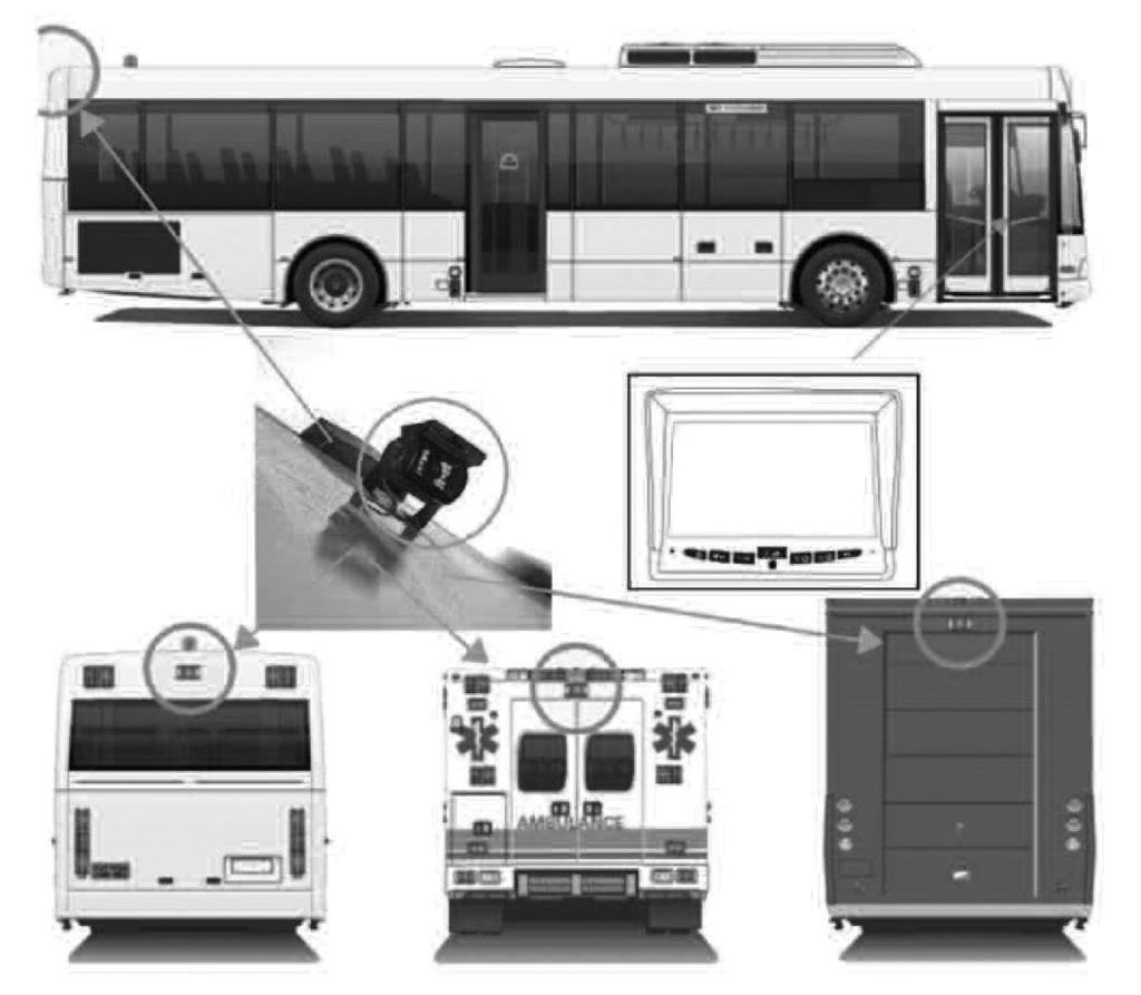
15 Positioning 15
16 Troubleshooting Monitor Displays Blue Screen & Displays "No Signal" Do a hard reset, disconnect monitor and camera(s) from power for 1 minute. Reconnect. Check that the camera is receiving +12VDC and that it has a clean and tight ground connection. Verify that the camera is paired to the monitor by following the procedure on page 10. Verify that the trigger on power harness is put to power +12VDC. Verify that vehicle voltage is above 12VDC at all spliced locations. Monitor Will Not Power-Up (no backlight on power) Check fuse Check +12VDC connection Check ground connection Try power and ground direct to battery No Image On Screen Verify camera is on correct camera input Verify monitor power cable is connected. Verify camera power cable is connected. Connect known working camera and cable to monitor. Verify trigger source is supplying power Verify power at all connections Verify camera pairing 16
17 Warranty Two Year Warranty Buyers Products Company, Inc. warrants this product against material defects for a period of two years from date of purchase. We reserve the right to repair or replace any such defective unit at our sole discretion. Buyers Products Company, Inc. is not responsible for a defect in the system as a result of mis-use, improper installation, damage or mishandling of the electronic components. Buyers Products Company, Inc. is not responsible for consequential damages of any kind. This warranty is void if: defects in materials or workmanship or damages result from repairs or alterations which have been made or attempted by others or the unauthorized use of nonconforming parts; the damage is due to normal wear and tear, this damage is due to abuse, improper maintenance, neglect or accident; or the damage is due to use of the Buyers Products Company, Inc. system after partial failure or use with improper accessories. Warranty Performance DURING THE ABOVE WARRANTY PERIOD, SHOULD YOUR Buyers Products Company PRODUCT EXHIBIT A DEFECT IN MATERIAL OR WORK- MANSHIP, SUCH DEFECT WILL BE REPAIRED WHEN THE COMPLETE Buyers Products Company, INC. PRODUCT IS RE-TURNED, POSTAGE PREPAID AND INSURED, TO Buyers Products Company, INC. OTHER THAN THE POSTAGE AND INSURANCE REQUIREMENT, NO CHARGE WILL BE MADE FOR REPAIRS COVERED BY THIS WARRANTY. Warranty Disclaimers NO WARRANTY, ORAL OR WRITTEN, EXPRESSED OR IMPLIED, OTH- ER THE ABOVE. WARRANTY IS MADE WITH REGARD TO THIS Buyers Products Company, INC. Buyers Products Company, INC. DISCLAIMS ANY IMPLIED WARRANTY OR MERCHANT-ABILITY OR FITNESS FOR A PARTICULAR USE OR PURPOSE AND ALL OTHER WARRANTIES IN NO EVENT SHALL Buyers Products Company. INC. LIABLE FOR ANY INCI- DENTAL, SPECIAL, CONSEQUENTIAL, OR PUNITIVE DAMAGES OR FOR ANY COSTS, ATTORNEY FEES, EXPENSES, LOSSES OR DELAYS AL- LEGED TO BE AS A CONSEQUENCE OF ANY DAMAGE TO, FAILURE OF, OR DEFECT IN ANY PRODUCT INCLUDING, BUT NOT LIMITED TO, ANY CLAIMS FOR LOSS OF PROFITS. 17
18 Disclaimer Buyers Products Company and/or its affiliates does not guarantee or promise that the user of our systems will not be in/part of an accident or other-wise not collide with an object and/or person. Our systems are not a substitute for careful and cautious driving or for the consistent adherence to all applicable traffic laws and motor vehicle safety regulations. The Buyers Products Company products are not a substitute for rear view mirrors or for any other motor vehicle equipment mandated by law. Our camera systems have a limited field of vision and do not provide a comprehensive view of the rear or side area of the vehicle. Always make sure to look around your vehicle and use your mirrors to confirm rearward clearance and that your vehicle can maneuver safely. Buyers Products Company and/ or its affiliates shall have no responsibility or liability for damage and/or injury resulting from accidents occurring with vehicles having some of Buyers Products Company products installed and Buyers Products Company and/or its affiliates, the manufacturer, distributor and seller shall not be liable for any in-jury, loss or damage, incidental or consequential, arising out of the use or intended use of the product. In no event shall Buyers Products Company and/or its affiliates have any liability for any losses (whether direct or indirect, in contract, tort or otherwise) incurred in connection with the systems, including but not limited to damaged property, personal injury and/or loss of life. Neither shall Buyers Products Company and/or its affiliates have any responsibility for any decision, action or inaction taken by any person in reliance on Buyers Products Company systems, or for any delays, inaccuracies and/or errors in connection with our systems functions. 18
19 If you have questions about this product, contact: 9049 Tyler Blvd. Mentor, Ohio Phone (440) Fax IN NO EVENT SHALL SELLER OR MANUFACTURER BE LIABLE FOR ANY DIRECT OR CONSEQUENTIAL DAMAGES OF ANY NATURE, OR LOSSES OR EXPENSES RESULTING FROM ANY DEFECTIVE PRODUCT OR THE USE OF ANY PRODUCT. 19
20 INST_A
Instruction Manual. 2.4G Digital Wireless Four Channel Transmitter System RVS-554W. Reverse With Confidence 1
 Instruction Manual 2.4G Digital Wireless Four Channel Transmitter System RVS-554W 1 NOTE! Please read all of the installation instructions carefully before installing the product. Improper installation
1 Split Screen Digital Wireless Monitor with Cigarette Lighter Adaptor 1 CCD Wireless Backup Camera with Power Cable 1 Extendable Suction Cup Mount
 What s in the Box? 1 Split Screen Digital Wireless Monitor with Cigarette Lighter Adaptor 1 CCD Wireless Backup Camera with Power Cable 1 Extendable Suction Cup Mount for Monitor Table of Contents Introduction...4
Instruction Manual. 7" Wireless Camera System with Wired Side Camera Inputs RVS-355W. Reverse With Confidence 1
 Instruction Manual 7" Wireless Camera System with Wired Side Camera Inputs RVS-355W Reverse With Confidence 1 RVS-355W.indd 1 10/2/2017 3:33:32 PM TABLE OF CONTENTS Introduction..............................
Safety Information. Camera System. If you back up while looking only at the monitor, you may cause damage or injury. Always back up slowly.
 Table of Contents Introduction...3 Safety Information...4-6 Before Beginning Installation...7 Installation Guide...8 Wiring Camera & Monitor...9-10 Replacement Installation Diagram...11 Clip-On Installation
Instruction Manual. Wireless Transmitters (Digital) RVS-550W. Reverse With Confidence 1
 RVS-550W. Reverse With Confidence 1") Instruction Manual Wireless Transmitters (Digital) RVS-550W Reverse With Confidence 1 TABLE OF CONTENTS In The Box 1 x Transmitter 1 x Receiver TABLE OF CONTENTS Table of Contents................................
Instruction Manual Wireless Transmitters (Digital) RVS-550W Reverse With Confidence 1 TABLE OF CONTENTS In The Box 1 x Transmitter 1 x Receiver TABLE OF CONTENTS Table of Contents................................
What s in the Box? RVS SYSTEMS
 TM 1 What s in the Box? 1 Color CCD Infra-red Weather Proof Camera 1 7" LED Color Monitor w/universal Mount/Stand & Wire 1 3 Channel Multiplexer Control Unit 1 66 Camera Cable 1 Remote Control 1 Power
Instruction Manual. OEM G-Series Backup Camera System with Frameless Mirror Monitor RVS Reverse With Confidence 1
 Instruction Manual OEM G-Series Backup Camera System with Frameless Mirror Monitor RVS-218640 Reverse With Confidence 1 TABLE OF CONTENTS Introduction.............................. 03 Safety Information..............................
what s in the Box? Camera transmitter with power cable 3M sticker 2 RVS SYSTEMS
 TM 1 what s in the Box? Camera transmitter with power cable 3M sticker 2 RVS SYSTEMS table of Contents introduction...4 features...5 Specifications...6-7 installation...8-9 Operations...10-15 Disclaimer...16
Instruction Manual. Wireless Safety Camera System for Forklifts with 5" Dual Screen Display RVS Reverse With Confidence 1
 Instruction Manual Wireless Safety Camera System for Forklifts with 5" Dual Screen Display RVS-655155 Reverse With Confidence 1 TABLE OF CONTENTS Introduction.............................. 03 Safety Information..............................
Digital Tiny Traveler Wireless Baby Monitor for Your Car
 Digital Tiny Traveler Wireless Baby Monitor for Your Car BT53901F-1 USER MANUAL ML-53901F_V1 IF YOU ARE EXPERIENCING ANY ISSUES WITH THE PRODUCT DURING OPERATION, DO NOT RETURN THE PRODUCT TO THE STORE.
Owner s Manual. Backup Monitor System. LCD Monitor & CCD Color Camera
 Backup Monitor System LCD Monitor & CCD Color Camera Backup Monitor System Copyright 2003 TMI Products, Inc. All Rights Reserved Corona, CA U.S.A. 060300 Owner s Manual 1493 Bentley Drive Corona, CA 92879
OWNER S MANUAL MOTORIZED 7 WIDE TFT LCD COLOR MONITOR CNT-701
 OWNER S MANUAL PW MOTORIZED 7 WIDE TFT LCD COLOR MONITOR CNT-701 ANY CHANGES OR MODIFICATIONS IN CONSTRUCTION OF THIS UNIT DEVICE WHICH IS NOT APPROVED BY THE PARTY RESPONSIBLE FOR COMPLIACE COULD VOID
AWT150C/AWT150CS/ AWT151C CCD Camera
 AWT150C/AWT150CS/ AWT151C CCD Camera ISSUED OCTOBER 2018 WARNING Failure to follow all instructions and safety precautions in this manual, in the vehicle and body manufacturers' manuals and on the safety
AOM FLAT PANEL COLOR OBSERVATION MONITOR OWNER S MANUAL
 R AOM681 6.8 FLAT PANEL COLOR OBSERVATION MONITOR OWNER S MANUAL AOM681 Features:? 6.8 High Performance Color LCD? Water Resistant Design? Built-in Audio Speaker with Volume Control and 12V Trigger? 2
Be sure to check the camera is properly functioning, is properly positioned and securely mounted, every time you operate your vehicle.
 Please read all of the installation instructions carefully before installing the product. Improper installation will void manufacturer s warranty. The installation instructions do not apply to all types
Garmin GC 10 Marine Camera Instructions
 Garmin GC 10 Marine Camera Instructions FCC Compliance This device complies with part 15 of the FCC Rules. Operation is subject to the following two conditions: (1) this device may not cause harmful interference,
SV-LCD50. Installation and User Guide. Thin-Film Transistor (TFT) Liquid Crystal Display (LCD) Color Rear Vision Monitor. Version 1.
 Liquid Crystal Display (LCD) Color Rear Vision Monitor. Version 1.") SV-LCD50 Installation and User Guide Thin-Film Transistor (TFT) Liquid Crystal Display (LCD) Color Rear Vision Monitor Version 1.00 August 2004 SV-LCD50 Installation and User Guide TFT LCD Color Rear Vision
SV-LCD50 Installation and User Guide Thin-Film Transistor (TFT) Liquid Crystal Display (LCD) Color Rear Vision Monitor Version 1.00 August 2004 SV-LCD50 Installation and User Guide TFT LCD Color Rear Vision
Indoor/Outdoor Security System with Quad Monitor User s Manual
 Indoor/Outdoor Security System with Quad Monitor User s Manual 4919539 Important! Please read this booklet carefully before installing or using these units. WARNING - These units should ONLY be opened
SM-816DT User s Manual. 2.4GHz Digital Wireless Outdoor/Indoor Camera with Night Vision and Audio
 SM-816DT User s Manual 2.4GHz Digital Wireless Outdoor/Indoor Camera with Night Vision and Audio Copyright 2012 This manual is furnished under license and may be used or copied only in accordance with
Do not install and/or operate this safety product unless you have read and understand the safety information contained in this manual.
 Installation and Operation Instructions CD3766 Directional LED Available in various color combinations, the CD3766 Directional LED is a surface mount, dual color warning light that is ideal for a wide
SC-C1M SiriusConnect TM Vehicle Tuner
 SC-C1M SiriusConnect TM Vehicle Tuner For Special Market Applications Installation Guide Congratulations on the Purchase of your new SIRIUS SC-C1 SiriusConnect TM Vehicle Tuner. The SC-C1M is packaged
JS007WQK HEAVY DUTY WIRELESS REVERSING KIT 7 LCD DIGITAL QUAD RECORDING MONITOR with WATERPROOF CCD CAMERA
 JS007WQK HEAVY DUTY WIRELESS REVERSING KIT 7 LCD DIGITAL QUAD RECORDING MONITOR with WATERPROOF CCD CAMERA The JS007WQK is loaded with userfriendly features and is ideal for use in heavy duty vehicles.
Model: LCD4WM 3.5 Window Mounted LCD Monitor User Manual Features
 Model: LCD4WM 3.5 Window Mounted LCD Monitor User Manual Features 3.5 High Resolution TFT LCD Monitor Low Profile, Slim Design Fully Adjustable reversing guidelines Built in Speaker Two video inputs Fully
CM-S38901SV TVL IR Long Range camera
 5 40 TVL IR Long Range camera User s Guide CM-S38901SV SAFETY PRECAUTIONS WARNING 1. Be sure to use only the standard adapter that is specified in the specification sheet. Using any other adapter could
Warning and Safety Information. FCC Information
 Installation Manual Warning and Safety Information FCC Information This device complies with FCC Rules Part 15 Operation and is subject to the following two conditions: (1) This device may not cause harmful
VMA573 and VMA or 7 Wide Screen Color LCD Monitor. Owner s Manual. Installation Guide
 VMA573 and VMA773 5.6 or 7 Wide Screen Color LCD Monitor Owner s Manual Installation Guide 7 headrest / stand alone wide monitor 5.6 headrest / stand alone wide monitor 2 WARINING! The Clarion VMA 573
Instruction Guide. The TV Jockey Computer Monitor TV Tuner with Remote COMP2VGATVGB. The Professionals Source For Hard-to-Find Computer Parts
 VIDEO ADAPTER The TV Jockey Computer Monitor TV Tuner with Remote COMP2VGATVGB Instruction Guide * Actual product may vary from photo The Professionals Source For Hard-to-Find Computer Parts FCC COMPLIANCE
Advanced security made easy PRO-555. Day/Night CCD Security Camera. Operating Instructions SW331-PR5 SR331-PR
 Advanced security made easy PRO-555 Day/Night CCD Security Camera Operating Instructions SW331-PR5 www.swannsecurity.com SR331-PR5-60010-260809 1 Before You Begin FCC Verification: NOTE: This equipment
FD70CV-M-C-9. Installation and Operation Manual. 7 NVG Compatible LCD. Revision Date: 06/16/2017 Page 1 of 12. Rev: A
 Page 1 of 12 Installation and Operation Manual FD70CV-M-C-9 7 NVG Compatible LCD Page 2 of 12 Specifications Display FD70CV-M-C-9 Panel Technology Diagonal Screen Size Native Resolution Pixel Pitch TN,
TECHNICAL SUPPORT , or FD151CV-LP Installation and Operation Manual 15.1 Low Profile LCD
 TECHNICAL SUPPORT 678-867-6717, or www.flightdisplay.com FD151CV-LP Installation and Operation Manual 15.1 Low Profile LCD FD151CV-LP 15.1" Low Profile LCD 2006 Flight Display Systems. All Rights Reserved.
CM-S23349SV. Vari-Focal IR Bullet Camera
 Vari-Focal IR Bullet Camera User s Guide CM-S23349SV SAFETY PRECAUTIONS WARNING 1. Be sure to use only the standard adapter that is specified in the specification sheet. Using any other adapter could cause
7 LCD Color Monitor 8 LCD Color Monitor OWNER S MANUAL
 7 LCD Color Monitor 8 LCD Color Monitor OWNER S MANUAL INTRODUCTION OHM720, OHM820 The Clarion OHM720/OHM820 is a full-featured 7 /8 LCD Color Monitor that can be used as a stand-alone monitor, or can
DUOVIEW FRONT AND REAR CAMERA SYSTEM
 DUOVIEW FRONT AND REAR CAMERA SYSTEM TABLE OF CONTENTS 1. Introduction...1 2. Package Contents...2 3. Product Specifications...3 4. Safety Information...5 5. Operation...6 6. Settings...9 7. Viewing Files...12
Outdoor IR Audio Camera
 Outdoor IR Audio Camera User s Guide CM-S22326BW-AD SAFETY PRECAUTIONS WARNING 1. Be sure to use only the standard adapter that is specified in the specification sheet. Using any other adapter could cause
EZ-LIGHT K30L Series With Independent Push Button Contact
 EZ-LIGHT K0L Series With Independent Push Button Contact Datasheet Compact with One, Two, or Three s and a Momentary Push Button Output Rugged, cost-effective and easy-to-install multicolor indicator light
Table of Contents. Introduction Pin Description Absolute Maximum Rating Electrical Specifications... 4
 Table of Contents Introduction... 1 Pin Description... 2 Absolute Maximum Rating... 3 Electrical Specifications... 4 Mechanical Specifications... 5 Thermal Specifications... 6 Over Temperature Protection...
User Manual Part Number: DMOV 7M C2
 TROUBLESHOOTING Problem No picture, no sound No picture No sound Dark picture No color Upside down or lateral inverted picture Event Triggers not activating (i.e. No picture during triggered event) Remote
VHF + UHF Amplified HDTV Antenna Model OA8000 & OA8001 Installation Instructions Reception Frequencies
 VHF + UHF Amplified HDTV Antenna Model OA8000 & OA8001 Installation Instructions Reception Frequencies VHF: 54-216 MHz UHF: 470-698 MHz FM: 87.9-107.9 MHz Voltage Input: AC110-120V / AC220-240V Working:
900-Lumen Portable LED Projector Part #: User manual
 900-Lumen Portable LED Projector Part #: 21797 User manual 900-Lumen LED Projector Manual Page 2 of 14 900-Lumen LED Projector Manual Page 3 of 14! SAFETY WARNINGS AND CAUTIONS WARNING: To reduce the risk
Table of contents. Opening the Overhead Monitor... 4 Precautions Care And Maintenance... 5 Operating OHM102/153 Monitor...
 Warning! The Clarion OHM102/OHM153 overhead monitor systems are designed for strictly for rear seat entertainment. Viewing the monitor while operating a motor vehicle can result in serious injury and/or
Indoor/Outdoor Analog Wired Camera Model P-520 USER'S MANUAL
 Indoor/Outdoor Analog Wired Camera Model P-520 USER'S MANUAL WELCOME Welcome Thank you for choosing First Alert for your security needs! For more than half a century, First Alert has made the home-safety
instruction manual video scan reverser models NVCN422CS & NVCN422C
 instruction manual video scan reverser models NVCN422CS & NVCN422C s/n boulder, colorado WARNING This equipment generates, uses and can radiate radio frequency energy and if not installed and used in accordance
CR-R880-BL: Indoor/Outdoor Proximity Reader with 10cm (4in) read range
 read range") CR-R880-BL: Indoor/Outdoor Proximity Reader with 10cm (4in) read range Installation Manual Table of Contents Basic Operation...2 CR-R880-BL Block Diagram...2 Technical Specifications...3 Features...4
CR-R880-BL: Indoor/Outdoor Proximity Reader with 10cm (4in) read range Installation Manual Table of Contents Basic Operation...2 CR-R880-BL Block Diagram...2 Technical Specifications...3 Features...4
Quick Installation Guide. Indoor / Outdoor Antenna, Antenna Cable & Surge Arrestor
 Quick Installation Guide Indoor / Outdoor Antenna, Antenna Cable & Surge Arrestor Table of Contents... 1 1. Outdoor Antenna Installation... 1 2. How to install the surge arrestor... 4 3. Weatherproof tape
Dakota Micro, Inc. Users Manual. Digital Wireless Two Camera Monitoring System Part Number: DMOV DW7MC2
 Users Manual Digital Wireless Two Camera Monitoring System Part Number: DMOV DW7MC2 Table of Contents I. Included Wireless Kit Components 2 II. Optional Wireless Kit Components 2 III. Standard Features
HDMI Extender over UTP Cable
 User Manual HDMI Extender over UTP Cable VHDE-300 Tx Rx Features.. Extends HDMI 1080p AV and IR Signals Transmission distance up to 60m/200ft via CAT6 cable or higher grade cable 5V DC, 1A Important Safety
OWNER'S MANUAL SIGNAL COMMANDER
 OWNER'S MANUAL SIGNAL COMMANDER THIS MANUAL CONTAINS INSTRUCTIONS FOR: LPDA 100 - INSTALLATION - OPERATION - TROUBLESHOOTING - EXPLODED PARTS DIAGRAM - WARRANTY AntennaTek, Inc. 425 S. Bowen, # 4 Longmont,
Omnidirectional TV/FM Antenna
 Omnidirectional TV/FM Antenna For Technical Services, email help@winegard.com or call 1-800-788-4417. DO NOT RETURN ANTENNA TO PLACE OF PURCHASE. DO NOT SNAP THE ANTENNA HEAD AND PEDESTAL TOGETHER PRIOR
Black & White Wireless Video Surveillance System
 MODEL: 2BWIR Black & White Wireless Video Surveillance System INSTALLATION MANUAL V1.0 N517 Camera Monitor - Compact 2.4 GHz Mini Black & White Camera - 5.5 High Resolution CRT - Sturdy Design with Metal
DSP x1 Color Screen Splitter Instruction Manual
 DSP-1200 2x1 Color Screen Splitter Instruction Manual Thank you for purchasing one of our products. Please read this manual before using this product. When using this product, always follow the instructions
Widescreen Headrest Monitor
 O W N E R S G U I D E INSTALLATION GUIDE MODEL HVM580 5.8 Widescreen Headrest Monitor 2005 Directed Electronics, Inc. N81580 02-05 NON-TRANSFERABLE LIMITED ONE YEAR CONSUMER WARRANTY Directed Electronics,
Linear Array with Intensity Adjustment
 Datasheet High-Power Lighting with Intensity Adjustment for use with Vision Systems For complete technical information about this product, including dimensions, accessories, and specifications, see www.bannerengineering.com/lineararraylights.
3.5 TFT LCD CCTV Service Viewer with Wristband
 User Manual 3.5 TFT LCD CCTV Service Viewer with Wristband LCD35SV It can proved the 12V DC power to camera for easy trouble shoot. LCD35SV is a type of product that summarizes views of first-line safety
VMA ACTIVE MATRIX TFT COLOR LCD MONITOR OWNER S MANUAL INSTALLATION GUIDE
 VMA6491 6.4 ACTIVE MATRIX TFT COLOR LCD MONITOR OWNER S MANUAL INSTALLATION GUIDE OWNER S MANUAL WARNING! THE CLARION VMA6491 LCD MONITOR IS DESIGNED FOR REAR SEAT PASSENGER VIEWING ONLY. THIS PRODUCT
Website: Tel: ADDRESS: 6475 Las Positas Rd. Livermore, CA Item No. E5B/E5S Installation Guide
 Website: www.flexispot.com Tel: -855-4-808 ADDRESS: 6475 Las Positas Rd. Livermore, CA 9455 Item No. E5B/E5S Installation Guide Specifications Step Column 3 Max. Weight Capacity 0 Ibs (00 kg) Speed 38mm/s
Introduction 2. Installation 3. Suggested Configuration 4. Using the Remote 5. Adjustment Mode 6. Technical Specifications 7. Technical Support 8
 1 Table of Contents Introduction 2 Installation 3 Suggested Configuration 4 Using the Remote 5 Adjustment Mode 6 Technical Specifications 7 Technical Support 8 Warranty Information 8 2 Introduction Thank
 www.greenelectricalsupply.com MaxLite 6 & 8 Commercial Downlight Retrofit General Safety Information To reduce the risk of death, personal injury or property damage from fire, electric shock, falling parts,
VOH681/VOH681P. ion Manual
 VOH681/VOH681P Operat ation ion Manual Important Notice It is unlawful in most jurisdictions for a person to drive a motor vehicle which is equipped with a television viewer or screen that is located in
PRO-ScalerHD2V HDMI to VGA & Audio Scaler Converter. User s Guide. Made in Taiwan
 PRO-ScalerHD2V HDMI to VGA & Audio Scaler Converter User s Guide Made in Taiwan Congratulations for owning a gofanco product. Our products aim to meet all your connectivity needs wherever you go. Have
SCIR. Infrared Illuminator Powerful Indoor/Outdoor IR Spotlight SCIR
 SCIR Infrared Illuminator Powerful Indoor/Outdoor IR Spotlight The NetMedia SCIR Infrared (IR) Illuminator provides night vision for IR (850nm) sensitive cameras. It enables cameras such as NetMedia s
OWNER'S MANUAL SIGNAL COMMANDER
 OWNER'S MANUAL SIGNAL COMMANDER THIS MANUAL CONTAINS INSTRUCTIONS FOR: LPDA 200 - INSTALLATION - OPERATION - TROUBLESHOOTING - EXPLODED PARTS DRAWING - WARRANTY AntennaTek, Inc. 425 S. Bowen, #4 Longmont,
FD104CV. Installation and Operation Manual 10.4 LCD MAN FD104CV. TECHNICAL SUPPORT , or Document Number: Rev:
 Page 1 of 16 FD104CV Installation and Operation Manual 10.4 LCD TCHNICAL SUPPORT 678-867-6717, or www.flightdisplay.com Page 2 of 16 FD104CV 10.4 LCD 2006 Flight Display Systems. All Rights Reserved. Flight
Operation Manual VMS 3.0 Video System
 Operation Manual VMS 3.0 Video System for the AlterG Anti-Gravity Treadmill 1 This manual covers operation procedures for the following AlterG products: AlterG Video System model VMS 3.0 NOTE: The following
AN2 Series. 900tvl. CMOS Technology High Resolution Sensor. elinetechnology.com P/N 01.BSM V1.0
 AN2 Series 900tvl CMOS Technology High Resolution Sensor P/N 01.BSM.16.2000030 V1.0 Product Made in China under ISO9001 & ISO1400 standards Manual Printed in China v1.0 elinetechnology.com CAUTION RISK
The specially designed stand (Included) made possible to use it indoor as well.
 made possible to use it indoor as well.") Instruction manual Terrestrial Digital TV Antenna Model: UDF-60 Indoor / Outdoor Thin design UHF Antenna Thank you for purchasing Nippon Antenna product. Please read this manual carefully before using
Instruction manual Terrestrial Digital TV Antenna Model: UDF-60 Indoor / Outdoor Thin design UHF Antenna Thank you for purchasing Nippon Antenna product. Please read this manual carefully before using
Operating Instructions
 Operating Instructions Digital LCD Color Monitor Please read this manual thoroughly before operating the unit, and keep it for future reference. V1.0 Contents 1. Precautions 2. Features 3. Technical Specifications
WINEGARD INSTALLATION MANUAL. Model GM Carryout Ladder Mount for mounting pipes with outer diameters between 1 to 1-1/8
 WINEGARD INSTALLATION MANUAL Model GM-3000 Carryout Ladder Mount for mounting pipes with outer diameters between 1 to 1-1/8 WARNING: DO NOT USE THE LADDER MOUNT AS A STEP! NOT INTENDED FOR USE WITH THE
LED Series Sealed Backlights
 For use with any Vision system Rugged, waterproof housing, rated IEC IP67 Mounts directly from the back or surface mount using available brackets Smooth exterior for easy cleaning Diffused backlights for
ISIS intouch NET Wi Fi Touch Screen Controller Owner s Manual and Instruction Guide
 ISIS intouch NET Wi Fi Touch Screen Controller Owner s Manual and Instruction Guide Table of Contents Overview... 2 Warnings... 3 Kit Includes... 4 Installation Steps... 5 Locate the intouch NET module
TVAC20000 User manual
 TVAC20000 User manual Version 01/2010 Original English user manual. Keep for future use. 10 Introduction Dear Customer, Thank you for purchasing this product. This product meets the requirements of the
User Guide. Single-Link DVI Active Cable Extender. DVI-7171c
 User Guide Single-Link DVI Active Cable Extender DVI-7171c TABLE OF CONTENTS SECTION PAGE PRODUCT SAFETY...1 PRODUCT LIABILITY...1 1.0 INTRODUCTION...2 2.0 SPECIFICATIONS...3 3.0 PACKAGE CONTENTS...4 4.0
Quick Release Roof-Mount Kit MB700
 Quick Release Roof-Mount Kit MB700 Owner s Manual Thank you for purchasing a KING product! The KING Quick Release Roof-Mount provides a convenient way to securely mount your KING antenna to your vehicle,
Low Profile Digital HDTV Over-the-Air Antenna CONTENTS
 Low Profile Digital HDTV Over-the-Air Antenna w/built-in KING SureLock Digital TV Signal Meter Owner s Manual Roof Thickness: 1 to 4-1/2 Roof Thickness: 4-1/2 to 8 (when installed with KING extension #21850)
Operating Instructions
 Operating Instructions LCDRV700 Digital LCD Color Monitor Please read this manual thoroughly before operating the unit, and keep it for future reference. V1.0 Contents 1. Precautions 2. Features 1 3 3.
HDMI to Composite Converter. User s Guide
 1500548 HDMI to Composite Converter User s Guide We hope you enjoy your HDMI to Composite Converter from RadioShack. Add flexibility to your viewing experience by converting a digital HDMI video source
Installation Instructions Wireless Camera/Monitor System
 Installation Instructions Wireless Camera/Monitor System Introduction: The Gemineye wireless camera system features 2.4GHZ digital signal transmission and offers quality and functionality equal to wired
SOURCE COMMANDER MSS433 A/V SELECTOR OWNER S MANUAL INSTALLATION GUIDE
 SOURCE COMMANDER MSS433 R L V R L V R L V R L V M U L T I S T A T I O N A/V SELECTOR OWNER S MANUAL INSTALLATION GUIDE OWNER S MANUAL/INSTALLATION GUIDE WARNING! THE CLARION MSS433 MULTISTATION A/V SELECTOR
VMA5894 and VMA or 7 Wide Screen Color LCD Monitor
 VMA5894 and VMA7194 5.8 or 7 Wide Screen Color LCD Monitor Owner s Manual Installation Guide - WARNING! The Clarion VMA5894 and VMA7194 monitors are only designed to be viewed by rear-seat occupants. Digital
User Manual rev: Made in Taiwan
 CV-500S HDMI to Component/CVBS & Audio Scaler Converter User Manual rev: 131218 Made in Taiwan The CV-500S HDMI to Component/CVBS & Audio Scaler Converter has been tested for conformance to safety regulations
Owner s Manual. VL9000 Series HEADREST MONITOR SYSTEM
 VL9000 Series HEADREST MONITOR SYSTEM Copyright 2003 TMI Products, Inc. All Rights Reserved Corona, CA U.S.A. 060300 Owner s Manual 1493 Bentley Drive Corona, CA 92879 909-272-1996 800-624-7960 Fax 909-272-1584
True RMS AC/DC Mini Clamp Meter
 User's Guide True RMS AC/DC Mini Clamp Meter Model 380947 Introduction Congratulations on your purchase of the Extech 380947 True RMS Clamp Meter. This Clamp meter measures current up to 400A DC/AC and
Satellite Receiver. Chapter REMOTE CONTROL USING THE MENUS USING TEXT FIELDS. About Your Satellite Receiver. What you ll find in this chapter:
 Satellite Receiver About Your Satellite Receiver Chapter What you ll find in this chapter: REMOTE CONTROL USING THE MENUS USING THE MENUS USING TEXT FIELDS 3 Chapter 2 Remote Control REMOTE CONTROL The
KHT 1000C HV-Probe Calibrator. Instruction Manual
 KHT 1000C HV-Probe Calibrator Instruction Manual Copyright 2015 PMK GmbH All rights reserved. Information in this publication supersedes that in all previously published material. Specifications are subject
USER MANUAL Table of Contents
 USER MANUA Table of Contents Safety Information.. 3 Specifications.. 4 Main Power Connection.. 5 DMX-512 Connection... 5 Main Control Menu... 6 DMX Profile... 8 Rigging the Fixture....10 Cleaning & Maintenance...10
PRO-ScalerV2HD VGA to HDMI & Audio Scaler Converter. User s Guide. Made in Taiwan
 VGA to HDMI & Audio Scaler Converter User s Guide Made in Taiwan Congratulations for owning a gofanco product. Our products aim to meet all your connectivity needs wherever you go. Have fun with our products!
Be sure to run the vehicle engine while using this unit to avoid battery exhaustion.
 CAUTION: TO REDUCE THE RISK OF ELECTRIC SHOCK DO NOT REMOVE COVER (OR BACK) NO USER-SERVICEABLE PARTS INSIDE REFER SERVICING TO QUALIFIED SERVICE PERSONNE; Please Read all of these instructions regarding
User Manual. VGA to Component or Component to VGA Converter Scaler AT-VGA300CV
 User Manual VGA to Component or Component to VGA Converter Scaler AT-VGA300CV www.atlona.com TABLE OF CONTENTS 1. Introduction... 2 2. Package Includes... 2 3. Features... 2 4. Specification... 2 5. Panel
User Guide. HDMI Active Cable Extender. DVI-7370c
 User Guide HDMI Active Cable Extender DVI-7370c TABLE OF CONTENTS SECTION PAGE PRODUCT SAFETY...1 PRODUCT LIABILITY STATEMENT........................ 1 1.0 INTRODUCTION...2 2.0 SPECIFICATIONS...3 3.0 PACKAGE
Quick Installation Guide. Indoor / Outdoor Antenna, Antenna Cable & Surge Arrestor H/W: V2
 Quick Installation Guide Indoor / Outdoor Antenna, Antenna Cable & Surge Arrestor H/W: V2 Table of Contents English... 1 1. Outdoor Antenna Installation... 1 2. How to install the surge arrestor... 5 Troubleshooting...
User Guide. HDMI Fiber Optic Extender. DVI-7350a
 User Guide HDMI Fiber Optic Extender DVI-7350a Table of Contents Section Page Product Safety.................................... 1 1.0 Introduction...2 2.0 Specifications...3 3.0 Package Contents...3 4.0
FD171CV-C-4. Installation and Operation Manual. 17 HDSDI Special Mission Quad Monitor. Revision Date: 01/11/2017 Page 1 of 14.
 Page 1 of 14 Installation and Operation Manual FD171CV-C-4 17 HDSDI Special Mission Quad Monitor Page 2 of 14 Table of Contents General Information...3 Front View...3 Additional Information...3 Specifications...4
User Manual CC DC 24 V 5A. Universal Control Unit UC-1-E. General Information SET. Universal Control Unit UC-1 Of Central Lubrication PAUSE CONTACT
 Universal Control Unit UC-1-E User Manual General Information Universal Control Unit UC-1 Of Central Lubrication CC DC 24 V 5A / M 15 SL /MK 31 M Z 30 General Information Contents Universal Control Unit
Camera Observation System Connect up to 3 Cameras. Users Guide. Warning
 Camera Observation System Connect up to 3 Cameras Users Guide Warning Specification and users guide contents are subject to change without notification. Refer to this users guide before installing or operating
INSTALLATION MANUAL. ST-CVTSD520-WSD-W Smoke Detector Covert Camera. v1.2 8/11/11 1
 INSTALLATION MANUAL ST-CVTSD520-WSD-W Smoke Detector Covert Camera v1.2 8/11/11 1 PACKAGE CONTENTS This package contains: One ST-CVTSD520-WSD-W smoke detector covert camera One installation manual Mounting
VGA Extender over Single CAT 6 Cable with Audio Support. Model Extend both video and audio up to 1000 feet
 VGA Extender over Single CAT 6 Cable with Audio Support Model 103004 Extend both video and audio up to 1000 feet Utilize a Cat 6 cable instead of a bulky VGA cable Supports a local monitor and local speakers
FD104CV. Installation and Operation Manual 10.4 LCD. Revision Date: 08/01/2017 Page 1 of 14. Rev: G. Document Number: MAN FD104CV
 Page 1 of 14 Installation and Operation Manual FD104CV 10.4 LCD Page 2 of 14 Table of Contents eneral Information... 3 Front View... 3 Additional Information... 3 Specifications... 4 Installation Instructions...
QUICK START GUIDE SL-6. Powering and Wireless System for the 688 Field Production Mixer
 QUICK START GUIDE Powering and Wireless System for the 688 Field Production Mixer Welcome Thank you for purchasing the, the powering and wireless system that simplifies interconnection between the 688
Low Profile Digital HDTV Over-the-Air Antenna CONTENTS
 Low Profile Digital HDTV Over-the-Air Antenna Owner s Manual Roof Thickness: 1 to 4-1/2 Roof Thickness: 4-1/2 to 8 (when installed with KING extension #21850) OA8400 White OA8401 Black CONTENTS OPERATION
OWNER'S MANUAL SIGNAL COMMANDER
 OWNER'S MANUAL SIGNAL COMMANDER THIS MANUAL CONTAINS INSTRUCTIONS FOR: MOD 550 - INSTALLATION - OPERATION - TROUBLESHOOTING - EXPLODED PARTS DRAWING - WARRANTY AntennaTek, Inc. 425 S. Bowen, #4 Longmont,
BRIGHTLINK HD Video Wall Controller BRIGHTLINKAV.COM
 BRIGHTLINK HD Video Wall Controller MODEL: BL-VW22 Operating Instructions BRIGHTLINKAV.COM Dear Customer Thank you for purchasing this product. For optimum performance and safety, please read these instructions