distribution passives signia series
|
|
|
- Crystal Barker
- 6 years ago
- Views:
Transcription

1 distribution passives signia series SAL001_US_01
2 about dkt DKT develops optical and coaxial products for professional broadband operators and solution providers. The company was founded in Its headquarters are in Denmark and it has subsidiaries in Sweden, Finland and China. As a dynamic and innovative company, its ambition is to deliver the best and broadest selection of quality products and advice when it comes to optical, coaxial and HFC broadband networks. With thirtyfive years of experience in coaxial broadband networks, DKT offers a comprehensive product portfolio, making it a strong partner for broadband operators. The solid experience gained by DKT is reflected in its products, these being characterized by high quality, top performance and easy installation. DKT mission DKT mission is to be a strong partner in network products for European broadband operators and solution providers. Based on know-how and natural enthusiasm, good ideas are developed into successful products. This is done together with the customer, who furthermore appreciates the broad product range, the attractive quality/price level and the unique customized products. DKT s flexibility and proactive attitude assists in optimizing broadband networks. For further information please contact DKT at sales@dktcomega.com Scan the QR code to view the latest PDF version of this brochure. Product introduction... 3 Feature introduction... 5 Signia taps... 7 Signia splitters...11 Accessories for taps and splitters...13 Electrical features...15 Mechanical features...17 Environmental tests...19 Useful terms and standards...21
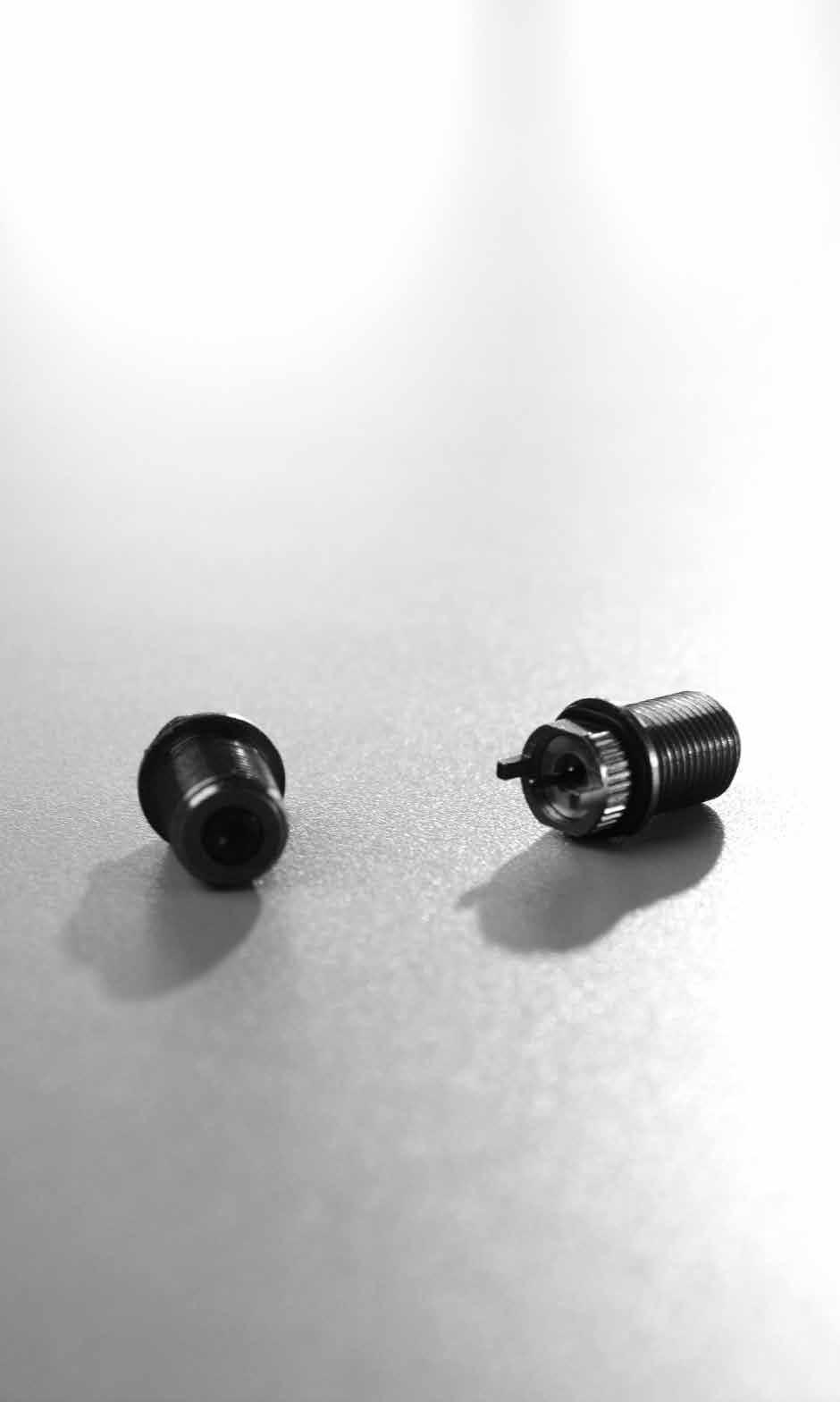
3 product introduction Introduction The demand for improved signal quality in coaxial networks is increasing, especially as subscribers expect triple play in broadband services. With many years of experience, DKT has a proven track record in the development and production of high performance broadband passives. The sum of experience and know-how combined with close cooperation with top operators has resulted in a state-of-the-art series of passives, the Signia line with nickel-tin brass connectors. With increased competition from fiber optical networks, it is nescessary to optimize the existing networks to be able to provide higher internetspeed, and increase competetiveness, and reduce cost of maintenance. These difficulties are not existing in optical networks for example because connectors do not loosen over time, therefore reducing OPEX in coaxial networks is crucial for staying competitive. The Signia line approaches and solves these problems by reducing the need for service visits to retighten connectors every now and then. This is achieved by crafting the connectors in the same metal and with the same alloy as the connectors used in CATV networks. Additionally the new spring mechanism that clamps around the inner conductor securing the connection even after continuously having inserted large inner conductors the spring still holds a firm grib even around slim inner conductors, this allows for maximum flexibility service without having to replace the units, due to wear and tear. So in short, what does this mean? Better economy due to reduced maintance cost/opex No maintenance required on distrution passives No interference due to return loss No noise due to surge pulses No replacement due to corrosion Faster installation with all ports facing the same direction Better economy due to reduced depreciation Long lifetime due to both mechanical and electrical design Increased service level and higher level of customer satisfaction Stable services. Happy customers and reduced churn as a result Increased revenue and ARPU Due to increased network performance more services can be delivered to end customers World class electrical and mechanical performance! All DKTCOMEGA's products comply with RoHS and WEEE directives. DKTCOMEGA follow the recommendations by CENELEC. For more information visit: WEEE For more information visit: approved 3
4 Advantages -
5 feature introduction Introduction The Signia series has been designed from scratch exploiting the many years of experience and know-how which has been generated in our value chain, from subcontractors as well as operators/service providers. The purpose of the section below is to give conclusions regarding what all these measurements, and features means in running a cable TV network. All the details for how this information was obtained can be found in the back. Electrical overview By using the Signia series of distribution passives it is possible to operate the network with a lower signal level, ultimately this will mean longer distance between each amplifier and thus reducing the cost of establishing and running the network. This can only be achieved due to several new features introduced in the Signia series. With the very high return loss, there is no need for preventive boosting of the signal level to suppress problems with noise and interference. The insertion loss following the attenuation curve of coaxial cable, the extremely flat tap loss, a very high isolation between outputs and excellent return loss levels, are all milestones. Furthermore the AC block and the resistance to passive intermodulation, and sturdy construction if exposed to high surge pulses provides excellent resistance and makes the networks even stronger/ more reliable. DKT are therefore proud to present a series of products which increases network performance & lifetime as well as makes network design & installation easier than ever. Mechanical overview The mechanical construction is extremely durable and is without comparisson the best DKT has ever designed, this will mean no impact on the mechanical performance from corrosion and the general environment, thus requiring no maintanance throughtout it s entire lifespan. Normally distribution passives require: Annual tightening of connectors to ensure connection Replacement in case of flooded installation site Stable environment The Signia series requires none of the above. This will eventually will lead to better options when choosing installation site, and lower cost of establishing as well as maintenance of the cable network. Enviromental test overview The Signia series of distribution passives can be mounted as any operator see fit, without considering how it will affect the network quality, not even in the long run. It is thus not absolutely necessary to use special cabinets to ward of salt, water and high temperatures. After having tested Signia the conclusion is that not even the most hostile environments have any particular impact on either the mechanical or electrical performance of the unit. The Signia series simply does not care about where it s mounted, it just works! 5
6 Advantages -
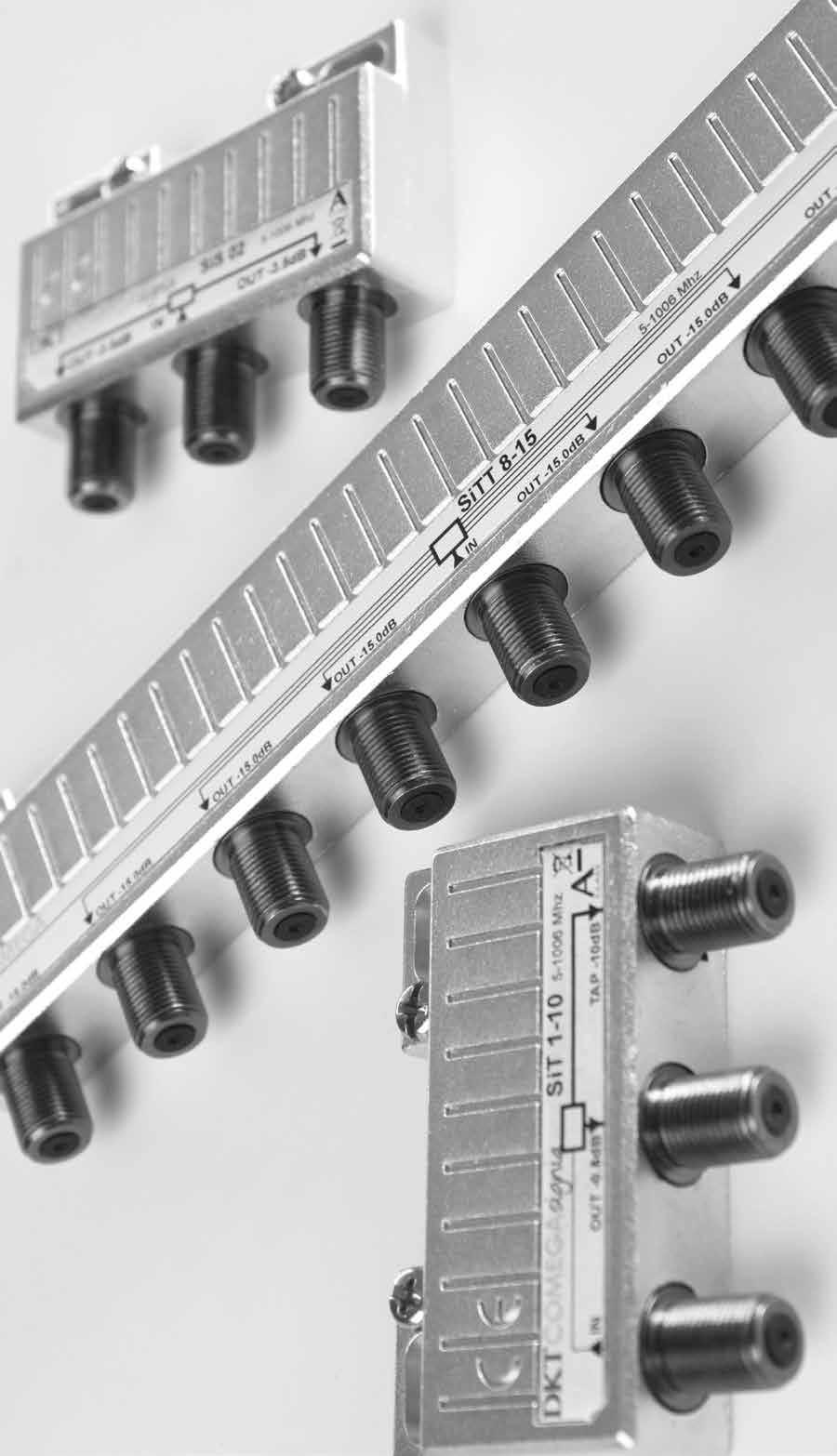
7 signia taps Product information The Signia tap series follows the tradition of the Master series. With reliable performance and superb specifications, this superior and comprehensive series includes 1-way through to 8-way taps with various attenuations. This optimizes network design options and efficiency. A lightweight design allows easy handling. Mounting spacers that are easily snapped on and off provide a choice for spacing underneath the taps allowing a more flexible installation. There is easy access to F-connectors which are mounted on the side. A unique construction of the female F-connector ensures secure connection to the inner conductor of the male connector, and furthermore the alloy ensures minimum Technical features Class A (page 16) corrosion. This dramatically reduces the likelihood of AC Block (page 16) signal dropout and the subsequent need for network Resistant to passive intermodulation (page 16) Surge pulse protection (page 16) troubleshooting. Protected against dust & humidity (page 17) Corrosion-free (page 17) The tap name, frequency range and all connectors are clearly marked with rugged labels. Model overview Type Product name Tap loss MHz Through loss MHz 1-way TAP 6 db SiT 1-6 6,5 2,2 1-way TAP 8 db SiT 1-8 8,5 1,6 1-way TAP 10 db SiT ,0 0,8 1-way TAP 12 db SiT ,0 0,7 1-way TAP 16 db SiT ,0 0,5 1-way TAP 20 db SiT ,0 0,5 1-way TAP 24 db SiT ,0 0,5 1-way TAP 30 db SiT ,0 0,5 2-way TAP 8 db SiT 2-8 8,5 3,3 2-way TAP 12 db SiT ,3 1,3 2-way TAP 16 db SiT ,0 1,1 2-way TAP 20 db SiT ,0 0,9 2-way TAP 24 db SiT ,0 0,9 3-way TAP 16 db SiT ,0 2,1 3-way TAP 20 db SiT ,0 1,4 4-way TAP 12 db SiT ,3 3,6 4-way TAP 16 db SiT ,0 2,3 4-way TAP 20 db SiT ,0 1,6 4-way TAP 24 db SiT ,0 1,2 4-way TAP terminated 12 db* SiTT ,0-6-way TAP terminated 14 db* SiT ,0-8-way TAP terminated 15 db* SiTT ,0 - * Internally terminated, no OUT port Standardization of Signia Taps The Signia tap series complies with a range of standards, below are some of the most relevant for cable TV networks. Description Name Conformity Description Name Conformity Dry Heat EN Change of temperature EN Return loss EN Grade 1 + Screening effectiveness EN Class A Protection against instrusion IEC IP67 Damp Heat EN Salt Mist EN Vibration EN Isolation (TAP-TAP) EN MHz: >20 db 7
 2.4 2.2 2.7 2.9 26 30 26 25 48106 SiT 1-8 8.7 (± 0.4) 8.4 (± 0.4) 2.1 1.7 2.0 2.3 34 35 33 30 48108 SiT 1-10 10.3 (± 0.4) 10.0 (± 0.3) 1.4 1.1 1.4 1.8 25 28 27 23 48110 SiT 1-12 12.2 (± 0.4) 12.")
 24.0 (± 0.3) 0.9 0.6 0.8 1.")
 Insertion loss IN-OUT (db) Isolation")
8 1 - way taps Type Tap loss IN-TAP (db) Insertion loss IN-OUT (db) Isolation TAP-OUT (db) Item no SiT (± 0.4) 6.6 (± 0.4) SiT (± 0.4) 8.4 (± 0.4) SiT (± 0.4) 10.0 (± 0.3) SiT (± 0.4) 12.0 (± 0.3) SiT (± 0.4) 16.0 (± 0.3) SiT (± 0.4) 20.0 (± 0.3) SiT (± 0.4) 24.0 (± 0.3) SiT (± 0.4) 30.1 (± 0.3) Return loss: Grade MHz: > 20 db Connectors: F-Female Dimensions: 65 x 50 x 16 mm Weight: 86 g 2 - way taps Type Tap loss IN-TAP (db) Insertion loss IN-OUT (db) Isolation TAP-OUT (db) Isolation TAP-TAP (db) Item no SiT (± 0.6) 8.3 (± 0.5) SiT (± 0.4) 12.3 (± 0.4) SiT (± 0.4) 16.3 (± 0.4) SiT (± 0.4) 20.0 (± 0.4) SiT (± 0.4) 24.1 (± 0.4) Return loss: Grade MHz: > 20 db Connectors: F-Female Dimensions: 109 x 50 x 16 mm Weight: 118 g 3 - way taps Type Tap loss IN-TAP (db) Insertion loss IN-OUT (db) Isolation TAP-OUT (db) Isolation TAP-TAP (db) Item no SiT (± 0.4) 16.1 (± 0.4) SiT (± 0.4) 19.9 (± 0.4) Return loss: Grade MHz: > 20 db Connectors: F-Female Dimensions: 109 x 50 x 16 mm Weight: 122 g
 12.4 (± 0.4) 4.3 3.6 4.3 5.0 33 38 30 29 41 48 40 40 48412 SiT 4-16 16.4 (± 0.4) 16.")
9 4 - way taps Type Tap loss IN-TAP (db) Insertion loss IN-OUT (db) Isolation TAP-OUT (db) Isolation TAP-TAP (db) Item no SiT (± 0.4) 12.4 (± 0.4) SiT (± 0.4) 16.0 (± 0.4) SiT (± 0.4) 20.0 (± 0.4) SiT (± 0.4) 24.2 (± 0.4) SiTT 4-12* 12.7 (± 0.5) 12.2 (± 0.4) * Internally terminated, no OUT port Return loss: Grade MHz: > 20 db Connectors: F-Female Dimensions: 196 x 50 x 16 mm Weight: 199 g 6 - way taps Type Tap loss IN-TAP (db) Insertion loss IN-OUT (db) Isolation TAP-OUT (db) Isolation TAP-TAP (db) Item no SiT 6-14* xx (± 0.5) xx (± 0.25) xx xx xx xx * Internally terminated, no OUT port Return loss: Grade MHz: > 20 db Connectors: F-Female Dimensions: 196 x 50 x 16 mm Weight: 207 g 8 - way taps Type Tap loss IN-TAP (db) Insertion loss IN-OUT (db) Isolation TAP-OUT (db) Isolation TAP-TAP (db) Item no SiT 8-15* 15.6 (± 0.5) 15.3 (± 0.5) * Internally terminated, no OUT port Return loss: Grade MHz: > 20 db Connectors: F-Female Dimensions: 196 x 50 x 16 mm Weight: 214 g 9
10 Advantages -
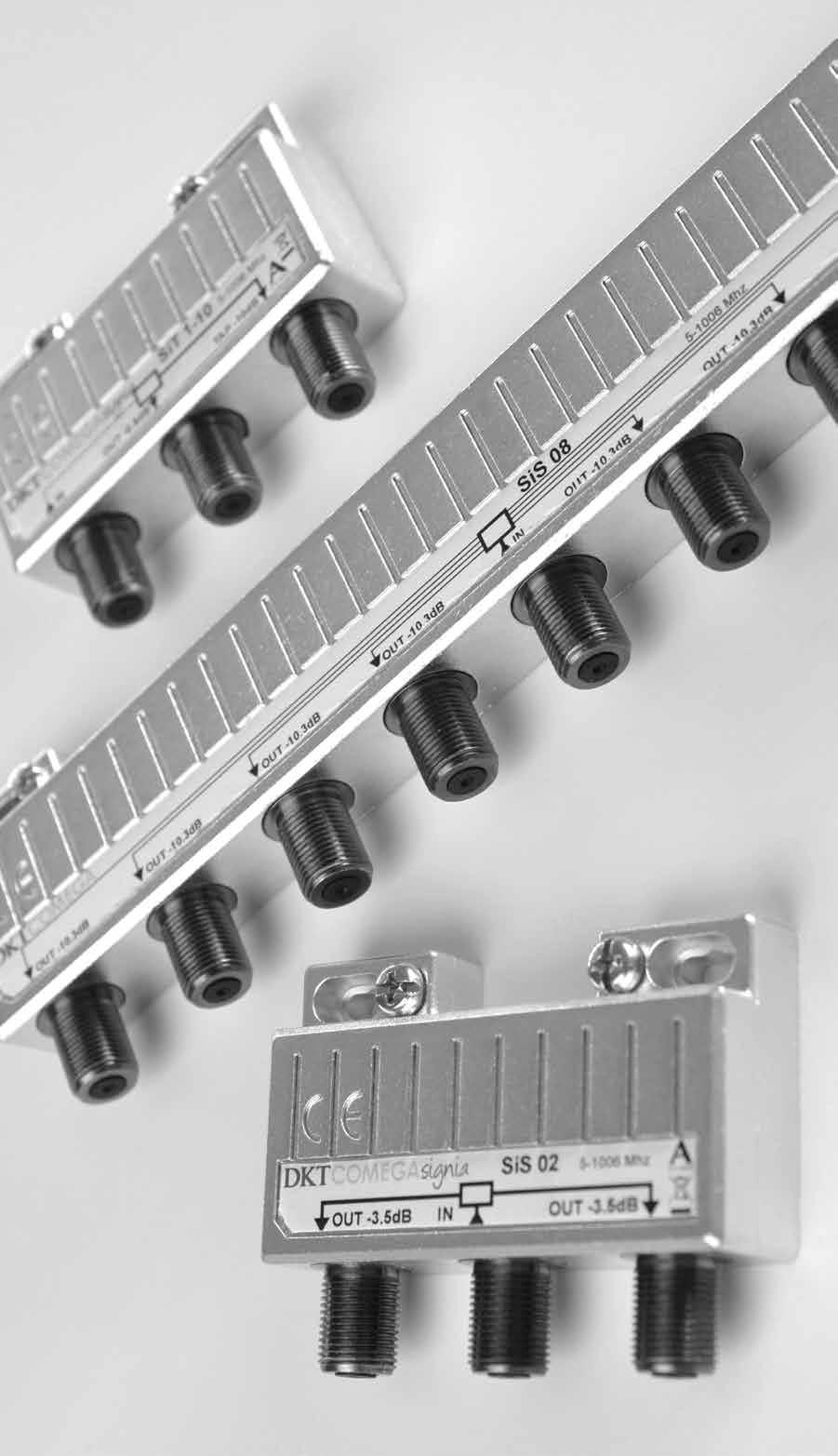
11 signia splitters Product information The Signia splitter series follows the tradition of the Master series. With reliable performance and superb specifications, this superior and comprehensive series includes 1-way through to 8-way splitters with various attenuations. This optimizes network design options and efficiency. A lightweight design allows easy handling. Mounting spacers that are easily snapped on and off provide a choice for spacing underneath the taps allowing a more flexible installation. There is easy access to F-connectors which are mounted on the side. A unique construction of the female F-connector ensures secure connection to the inner conductor of the male connector, and furthermore the alloy ensures minimum Technical features Class A (page 16) corrosion. This dramatically reduces the likelihood of AC Block (page 16) signal dropout and the subsequent need for network Resistant to passive intermodulation (page 16) Surge pulse protection (page 16) troubleshooting. Protected against dust & humidity (page 17) Corrosion-free (page 17) The tap name, frequency range and all connectors are clearly marked with rugged labels. Model overview Type Product name Splitter loss Mhz 2-way splitter SiS 02 3,4 3-way splitter SiS 03 5,4 3-way splitter asymmetric SiS 03A 3,4 / 6,8 4-way splitter SiS 04 6,8 6-way splitter SiS 06 8,6 8-way splitter SiS 08 10,3 Standardization of Signia Splitters The Signia splitter series complies with a range of standards, below are some of the most relevant for cable TV networks. Description Name Conformity Description Name Conformity Dry Heat EN Change of temperature EN Return loss EN Grade 1 + Screening effectiveness EN Class A Protection against instrusion IEC IP67 Damp Heat EN Salt Mist EN Vibration EN Isolation (TAP-TAP) EN MHz: >20 db 11

12 2 - way splitters Type Insertion loss IN-OUT (db ± 0.5) Isolation OUT-OUT (db) Item no SiS Return loss: Grade MHz: > 20 db Connectors: F-Female Dimensions: 65 x 50 x 16 mm Weight: 86 g 3 - way splitters Type Insertion loss IN-OUT (db ± 0.5) Isolation OUT-OUT (db) Item no SiS SiS 03A Return loss: Grade MHz: > 20 db Connectors: F-Female Dimensions: 109 x 50 x 16 mm Weight: 118 g 4 - way splitters Type Insertion loss IN-OUT (db ± 0.5) Isolation OUT-OUT (db) Item no SiS Return loss: Grade MHz: > 20 db Connectors: F-Female Dimensions: 109 x 50 x 16 mm Weight: 122 g


13 6 - way splitters Type Insertion loss IN-OUT (db ± 0.5) Isolation OUT-OUT (db) Item no SiS Return loss: Grade MHz: > 20 db Connectors: F-Female Dimensions: 196 x 50 x 16 mm Weight: 207 g 8 - way splitters Type Insertion loss IN-OUT (db ± 0.5) Isolation OUT-OUT (db) Item no SiS Return loss: Grade MHz: > 20 db Connectors: F-Female Dimensions: 196 x 50 x 16 mm Weight: 214 g accessories for signia taps and splitters All Signia taps & splitters have included a set of spacers to allow easy installation of cables underneath the units, with a height of 7 mm it allows space for the most commonly used installation cables. The spacers are easily snapped on if that extra space is desired when installing. 13

14


15 electrical features Frequency range The Signia products are designed to operate within the frequency range specified in DOCSIS 3.0 ( MHz). Insertion loss Insertion loss indicates how much of the signal strength is lost by leading the signal from IN to OUT. Signia is designed to provide the least possible insertion loss. The curve is optimized to be as flat as possible, to allow for high consistency in the signal passing through. The Signia series have been designed to simulate the attenuation of coaxial cable over the frequency range, there by making planning of the networks easier, and allows for easy calculating of equalizing in the amplifier. Tap loss Tap loss indicates how much of the signal strength is lost by leading the signal from IN to TAP. Some physical conditions makes it possible to further enhance tap loss in comparison to insertion loss. Which leads to a very flat curve for tap loss. The Signia series are on the tap loss designed to be as flat as possible, with a very small margin variyng only ±0.25 db over the entire frequency range. Loss measurement OUT TAP TAP LOSS INSERTION IN LOSS A signal is applied to the IN connector. For Tap Loss the output is measured on the other TAP connectors. For Insertion Loss the output is measured on the OUT connector. OUT OUT-TAP TAP ISOLATION Isolation measurement Tap Isolation Isolation is also an important factor, it indicates how effectively the unit negates interference from one output to another. There are 3 types of measurements, OUT-OUT, which is relevant for splitters, TAP-TAP and TAP-OUT which are relevant to taps. A high isolation between TAP-TAP means that noise from TAP1 does not interfere with signals or TAP2, and services as well as maintenance is optimized. The Signia TAP-TAP isolation is so high that it complies with EN requirements for isolation between two subscribers, without having to add any other equipment for additional isolation. Return loss For isolation measurements a signal is applied to a connector and the output is measured on the other connectors. Return loss is the measurement of how much of the signal is being reflected backwards in the system. All reflections in the network are not desired and the return loss should thus be as high as possible, and in a perfect network the return loss is indefinately high. A return loss of 3 db means that 50% of the signal is reflected back to the source, and with a 20 db return loss its only 1%. The Signia line is designed for maximum return loss, following the standardization of EN , where we achieve more than 20 db in the entire frequency range which fullfills the requirements for Grade 1 compliance. This provides a higher safety margin when projecting. OUT OUT-OUT ISOLATION TAP-TAP ISOLATION OUT TAP Splitter 15
16 Screening effectiveness/efficiency/rfi Screening effectiveness is the products ability to shield the internal print circuits from exterior electromagnetic interference and vice versa. The disturbance may interrupt, obstruct, or otherwise degrade or limit the effective performance of the circuit. These effects can range from a simple degradation of data to a total loss of data. The source may be any object, artificial or natural, that carries rapidly changing electrical currents, such as mobile broadband signals With an increasing amount of interfering signals in the surroundings, screening effectiveness is a more crucial matter than ever. With a screening effectiveness exceeding the requirements for Class A, the installation have a very high level of resistance to interference, which leads to less pixelation and signal outage. The graph shows the screening effectiveness measured according to EN in all of the Signia housings. For example, in cases with LTE/4G signals there will be no problems if the Signia series is used. High voltage blocking (AC) Built in surge protection against AC power. This eliminates problems with TVs discharging currents or possibly current surges from the network into the installation with the possibility damaging sensitive equipment. On all port a 1kV capacitor is installed; hence all devices are capable of withstanding up to 2kV between the inner conductors of any connection cables. 150 Class A Signia housing mm width house 109 mm width house 196 mm width house Passive intermodulation Passive intermodulation can occur in passive components such as taps and splitters, if the ferrite cores are saturated by too high signal levels. In such a situation the ferrite core becomes permanently magnetized and thereby decline permanently in linearity. The Signia series have been designed with ferrite cores with a very high saturation threshold, thereby providing resistance to passive intermodulation. Surge pulse protection Surge pulses are closely related to passive intermodulation, and is the measurement on the level of intermodulation after high pulses of signal level into the unit. The surge pulses are measured with two carriers 120 dbµv at 50 and 55 MHz OUT-IN. The level of resulting intermodulation product at 105MHz is recorded. For the two way splitter, SiS 02 the following results are obtained: No surge: Surge 10 pulses at 25V: Surge 1 pulse at 1kV: -6 dbµv at 105MHz -> PIM 126dB 16 dbµv at 105MHz -> PIM 104dB 19 dbµv at 105MHz -> PIM 101dB The recorded intermodulation signal at 105MHz after a sequence of 10 surge pulses at 25V and 1 surge pulse at 1kV. The level of the intermodulation signal is dbµv. The Signia series is constructed very sturdy when handling surge pulses, and it will take very large surges of signal before deteriorating the unit to a degree where the performance will decrease.
17 mechanical features Enclosure The Signia housing are cast in a zinc alloy, a backplate is sealed with a strong glue. The F-connector is fitted into DD hole in the housing and it is sealed with an O-ring. Finally the F-connector is designed with a rubber humidity membrane, which is perforated first when the product is installed. All these will make sure no water or dust will enter the housing. To ensure potential corrosion over a long period of time have no effect on the electrical performance, PCB connection pin the outershield of the F-connector is soldered directly onto the printed circiut board (PCB). Normally the outer shield of the F-connector is O-ring soldered to the housing and from there connected to the PCB, but as the housing can be more vulnerable to electrolytical corrosion as its made from zinc and not pure brass. If the housing was used as connection between the connected cables shield, and oxidises as part of the corrosion, it can act as a semiconductor, that will degrade the signal quality. The Signia housing has been tested under 1m water for 30min, corresponding to the IPx7 requirements. No water penetrated into the housing with the glue sealing, so the sealing between the back plate and the housing, and the sealing between the F-connector and the housing is water tight to at least 1m. Humidity membrane F-connector base Based on these results it is concluded that the Signia housing it-self is IP class 64 (dust and dripping water tight). With cables and/or terminators mounted on all ports it is concluded that the Signia housing is IP class 67. F-connector The Signia series F-connector follow the dimensions as standardized in ANSI/SCTE , the connector is made of pure brass which is the same metal as professionel connectors. Brass is a very stable metal compared to zinc which is usually used for casting F-connectors. This is especially important for components that often have filters swapped. Furthermore the connectors are plated with a nickel-tin alloy, ensuring a minimum corrosion over time, reducing the need to retighten connectors across the cabe network to near zero for the products lifespan. This is a common cause of errors in cable network and many hours per year can thus be saved. Clamping force The Clamp-claw inside the connector is made with a phosphor bronze alloy making it very flexible allowing insertion of small inner conductors even after large inner conductors have been fitted without loss of electrical performance, phosphor bronze have been chosen over beryllium copper because beryllium-containing alloys create an inhalation hazard during manufacturing due to their toxic properties. Furthermore the clamp-claw is plated with the same nickel-tin mixture as the F-connector. After the insertion of an inner conductor with a diameter of 1.3mm 5 times the F-connector is capable of carrying an inner conductor with a diameter of 1.0mm and with a weight of 250g. After the insertion of an inner conductor with a diameter of 1.2mm 3 times the F-connector is capable of carrying an inner conductor with a diameter of 0.64mm and with a weight of 34.5g. Cable tightening torque DKT have tested the Signia passives up to 11 Nm without observering any damage to the housing or connector. Outdoor female F ports shall be able to withstand a minimum tightening torque of 4.5Nm (40 in.-lb.), without damage when measured per IPS TP 253. This is achieved as a combination in the mechanical design in both the sturdiness of pure brass and DD shape of the connector insert. 17

18 Advantages - Environmentally friendly materials (RoHS & WEEE compliant) - Protected against AC surges - Seamlessly maintenance - Superb screening effectiveness with negligible RFI
19 environmental tests Introduction Taken into consideration how much effort there s been put into designing the ultimate series of distribution passives, it has been nescessary to accompany the excellent specifications with environmental tests of the mechanical and eletrical features, to prove the durability of both the exterior and interior of the Signia. Below are the test results, and the conclusion is that Signia suffers no crucial deterioration. Salt mist The Signia housing was exposed to salt mist according to EN : Concentration 5% Temperature +35 C Exposure time 16 hours Terminators are mounted on all F-connectors No residuals from salt are observed inside the housing after this test. On the outside of the housing deposit of salt is observed, but not on the F-connectors. In conclusion the electrical parameters are unaffected by the salt mist exposure. Vibration Some Signia samples were exposed to a sequence of Vibration Test according to EN : Frequency range Hz Sweep rate 1 octave per minute Sweep cycles 10 Displacement amplitude 0.75mm 3 Directions For the insertion loss an increase of maximum 0.5dB is observed, only at the highest frequencies. Also, the return loss and the isolation change after the test sequence, but in all cases the specifications are fulfilled. Dry heat Some Signia samples were exposed to a sequence of Dry Heat Test according to EN : Temperature +70 C Time 16 hours Relative humidity <30% For the insertion loss an increase of maximum 0.5dB is observed, only at the highest frequencies. Return loss and the isolation change after the test sequence, but in all cases the specifications are fulfilled. Change of temperature Some Signia samples were exposed to Change of Temperature according to EN : Low temperature -15 C High temperature +55 C Rate of temperature change 1 C per minute Number of cycles 5 Stable time at low and high temperature 3 hours All of the electrical parameters are still within the specifications after the test. Damp heat Some Signia samples were exposed to Damp Heat according to EN : Low temperature +25 C High temperature +40 C Number of cycles 21 Stable time at low and high temperature 12 hours Relative humidity >95% All of the electrical parameters are still within the specifications after the test. 19

20 Advantages - Superior electrical and mechanical performance - Best in class return on investment - Surge pulse protection, e.g. from the return path - Extremely long lifetime
21 useful terms and standards DOCSIS An international standard developed by major companies to define the communication and operation support interface requirements for data over cable systems. DOCSIS 1.0 was issued in March 1997, DOCSIS 2.0 in December 2001 and DOCSIS 3.0 in August With DOCSIS 3.0 the operating frequency range was expanded from MHz to MHz, allowing even higher data rates to be transmitted. Usually 5-15 MHz are not utilized for upstream transmissions, but are included in the standard, to allow buffering on the products so they are fully operational at 15 MHz, occasionally the 5-15 MHz band is used for measurement signals and other operator tools. IP As defined in international standard IEC 60529, IP Code classifies and rates the degrees of protection provided against the intrusion of solid objects (including body parts like hands and fingers), dust, accidental contact, and water in mechanical casings and with electrical enclosures. The first digit indicates the level of protection that the enclosure provides against access to hazardous parts (e.g., electrical conductors, moving parts) and the ingress of solid foreign objects. Level Object size protected against Effective against 0 No protection against contact and ingress of objects 1 >50 mm 2 >12.5 mm Fingers or similar objects 3 >2.5 mm Tools, thick wires, etc. 4 >1 mm Most wires, screws, etc. 5 Dust protected Any large surface of the body, such as the back of a hand, but no protection against deliberate contact with a body part Ingress of dust is not entirely prevented, but it must not enter in sufficient quantity to interfere with the satisfactory operation of the equipment; complete protection against contact 6 Dust tight No ingress of dust; complete protection against contact The second digit indicates protection of the equipment inside the enclosure against harmful ingress of water. Level Protected against Testing for Details 0 Not protected 1 Dripping water 2 Dripping water when tilted up to 15 3 Spraying water 4 Splashing water 5 Water jets 6 Powerful water jets 7 Immersion up to 1 m Dripping water (vertically falling drops) shall have no harmful effect. Vertically dripping water shall have no harmful effect when the enclosure is tilted at an angle up to 15 from its normal position. Water falling as a spray at any angle up to 60 from the vertical shall have no harmful effect. Water splashing against the enclosure from any direction shall have no harmful effect. Water projected by a nozzle (6.3mm) against enclosure from any direction shall have no harmful effects. Water projected in powerful jets (12.5mm nozzle) against the enclosure from any direction shall have no harmful effects. Ingress of water in harmful quantity shall not be possible when the enclosure is immersed in water under defined conditions of pressure and time (up to 1 m of submersion). Test duration: 10 minutes Water equivalent to 1mm rainfall per minute Test duration: 10 minutes Water equivalent to 3mm rainfall per minute Test duration: 5 minutes Water volume: 0.7 litres per minute Pressure: kn/m² Test duration: 5 minutes Water volume: 10 litres per minute Pressure: kn/m² Test duration: at least 3 minutes Water volume: 12.5 litres per minute Pressure: 30 kn/m² at distance of 3m Test duration: at least 3 minutes Water volume: 100 litres per minute Pressure: 100 kn/m² at distance of 3m Test duration: 30 minutes Immersion at depth of 1m 21


22
23 ANSI/SCTE A specification for F-type radio frequency connectors where the male pin or inner coaxial conductor may have a diameter from 0,51 to 1,63 mm. EN A standard dealing with cabled distribution systems for television, sound and interactive multimedia signals using all applicable transmission media. Developed by CENELEC the European Committee for Electrotechnical Standardization. Class A: Class B: MHz 85 db, MHz 80 db, MHz 75 db, MHz 55 db MHz 75 db, MHz 65 db, MHz 50 db EN A standard covering Cable networks for television signals, sound signals and interactive services. Passive wideband equipment for coaxial cable networks. It supersedes EN Among others it includes standardization of return loss. Grade 1: Grade 2: Grade 3: 5-40 MHz 22 db, MHz 22 db 1.5 db/oct. min. 14 db 5-40 MHz 18 db, MHz 18 db 1.5 db/oct. min. 10 db 5-40 MHz 14 db, MHz 14 db 1.5 db/oct. min. 10 db Triple Play The transfer of voice, video and data over broadband networks. 23
24 Scan the QR code to view the latest PDF version of this brochure.
SIGNIA01_EN_03.5. distribution passives signia series
 SIGNIA01_EN_03.5 distribution passives signia series about dkt DKT develops optical and coaxial products for professional broadband operators and solution providers. The company was founded in 1977. Its
distribution passives basic series
 distribution passives basic series SAL001_US_01 about dktcomega DKTCOMEGA develops optical and coaxial products for professional broadband operators and solution providers. The company was founded in 1977.
coaxial passives & accesories
 coaxial passives & accesories SAL011_US_01_DRAFT_B about dktcomega DKTCOMEGA develops optical and coaxial products for professional broadband operators and solution providers. The company was founded in
Drop Passives: Splitters, Couplers and Power Inserters
 ENGINEERING COMMITTEE Interface Practices Subcommittee AMERICAN NATIONAL STANDARD ANSI/SCTE 153 2016 Drop Passives: Splitters, Couplers and Power Inserters NOTICE The Society of Cable Telecommunications
THE EFFECT OF LOOSE CONNECTORS ON SHIELDING EFFECTIVENESS
 THE EFFECT OF LOOSE CONNECTORS ON SHIELDING EFFECTIVENESS Asheridge Communications (A Teleste PLC Company) has undertaken a study to further understand the issues of RFI (Radio Frequency Interference)
AMERICAN NATIONAL STANDARD
 ENGINEERING COMMITTEE Interface Practices Subcommittee AMERICAN NATIONAL STANDARD ANSI/SCTE 153 2008 Drop Passives: Splitters, Couplers and Power Inserters NOTICE The Society of Cable Telecommunications
Cisco 1.25 GHz Surge-Gap Passives
 Data Sheet Cisco 1.25 GHz Surge-Gap Passives The Cisco 1.2 GHz Surge-Gap Passives product line is the latest evolution of the HFC network providing full support of the DOCSIS 3.1 standard. DOSCIS 3.1 support
AMERICAN NATIONAL STANDARD
 Interface Practices Subcommittee AMERICAN NATIONAL STANDARD ANSI/SCTE 129 2017 Drop Passives: Bonding Blocks (Without Surge Protection) NOTICE The Society of Cable Telecommunications Engineers (SCTE) Standards
ENGINEERING COMMITTEE
 ENGINEERING COMMITTEE Interface Practices Subcommittee AMERICAN NATIONAL STANDARD ANSI/SCTE 01 2015 Specification for F Port, Female, Outdoor NOTICE The Society of Cable Telecommunications Engineers (SCTE)
GENESYS II SERIES 1 GENESYS I SERIES 5 DROP PASSIVES DROP PASSIVES. Drop Splitters 1 1-Way Directional Coupler 4
 GENESYS II SERIES 1 Drop Splitters 1 1-Way Directional Coupler 4 GENESYS I SERIES 5 Drop Splitters 5 1-Way Directional Coupler 8 GENESYS II PCT s Genesys II drop passives offer exceptional performance
LED MODULES READYLINE DL
 LED MODULES READYLINE DL BUILT-IN MODULE LED-MODULE READYLINE DOWNLIGHT DL WU-M-538 / WU-M-539 / WU-M-540 Typical Applications Downlights Replacement for CFL DIRECT MAINS CONNECTION REDUCED FLICKER HIGH
I/A Series Hardware Fiber Optic LAN Converter
 I/A Series Hardware PSS 21H-7F3 B4 The provides bidirectional conversion between coaxial and fiber optic media. The converter is compatible with existing I/A Series system hardware, utilizes industry standard
TV Radio Multimedia MHz amplifiers, distribution and connection technology. 99High output levels 99High reliability 99Maximum durability
 TV Radio Multimedia 1006 MHz amplifiers, distribution and connection technology High output levels High reliability Maximum durability On the right track CATV amplifiers AXING CATV amplifiers AXING amplifiers
Tap and Splitter series Platinum, Gold and Silver. triax.com splitters
 Tap and Splitter series Platinum, Gold and Silver triax.com splitters TRIAX Coaxial Taps and Splitters The Right Choice Selection of 4ranges PLATINUM GOLD SILVER OUTDOOR Triax has restructured and upgraded
RF connectivity solutions guide
 RF connectivity solutions guide CommScope RF connectivity solutions The pressure on MSOs has never been greater because subscriber expectations have never been higher. Whether streaming digital video or
Model Extend HDMI audio and video connections up to 300 feet. Add up to 8 additional receivers with a dedicated network switch
 HDMI Extender over Single CAT 6 Cable with IR Control Model 103002 Extend HDMI audio and video connections up to 300 feet Utilize existing Cat 6 wiring for an easy installation Add up to 8 additional receivers
Connecting cables NEBS, for sensors
 Connecting cables NEBS, for sensors Connecting cables NEBS, for sensors Product range overview Function Version Type code Connection technology (Electrical connection 2) Connecting cable Cable characteristic
1995 Metric CSJ SPECIAL SPECIFICATION ITEM 6031 SINGLE MODE FIBER OPTIC VIDEO TRANSMISSION EQUIPMENT
 1995 Metric CSJ 0508-01-258 SPECIAL SPECIFICATION ITEM 6031 SINGLE MODE FIBER OPTIC VIDEO TRANSMISSION EQUIPMENT 1.0 Description This Item shall govern for the furnishing and installation of color Single
TV Radio Multimedia. Optical Nodes, 1218 MHz and 1006 MHz amplifiers, distribution and connection technology
 TV Radio Multimedia Optical Nodes, 1218 MHz and 1006 MHz amplifiers, distribution and connection technology High output levels High reliability Maximum durability Optical Micro Fibre Node 1218 MHz FTTH/FTTB
SERIES BNC 50, COAXIAL MINIATURE CONNECTORS
 SERIES BNC 50, COAXIAL MINIATURE CONNECTORS DESCRIPTION CONTENTS PAGE HUBER+SUHNER BNC is still one of the most popular connector series, featuring a two stud bayonet coupling mechanism, which is particularly
User Manual CXE800. Fibre Optic Receiver. CXX Series. Teleste Corporation
 Broadband Cable Networks August 30, 2007 1(8) CXX Series User Manual Teleste Corporation CXE800 Fibre Optic Receiver Broadband Cable Networks August 30, 2007 2(8) Introduction The CXE800 is a unidirectional,
SPECIAL SPECIFICATION 1987 Single Mode Fiber Optic Video Transmission Equipment
 1993 Specifications CSJ 0027-12-086, etc. SPECIAL SPECIFICATION 1987 Single Mode Fiber Optic Video Transmission Equipment 1. Description. This Item shall govern for the furnishing and installation of color
.152 (3.86) KEYWAY DEPTH .033 (.84).066 (1.68) .550 DIA (13.97) MOUNTING SURFACE .350 (8.89) 3/8-32 UNEF-2A THREADS (19.71.
 KEYWAY DEPTH .033 (.84).066 (1.68) .550 DIA (13.97) MOUNTING SURFACE .350 (8.89) 3/8-32 UNEF-2A THREADS (19.71.") Optical SERIES 61K High Resolution, 4-Pin FEATURES 25, 32, 50, 64, 100, 128 and 256 Cycles per Revolution Available Sealed Version Available Rugged Construction Cable or Pin Versions 10 Million Rotational
Optical SERIES 61K High Resolution, 4-Pin FEATURES 25, 32, 50, 64, 100, 128 and 256 Cycles per Revolution Available Sealed Version Available Rugged Construction Cable or Pin Versions 10 Million Rotational
 www.mete-enerji.com.tr INDUSTIAL IEC PLUGS AND SOCKETS INDUSTIAL IEC PLUGS AND SOCKETS Position of the Earthing Contact acc. to IEC 60309-2 225/400-265/460 V~ 60 Hz (1) 3 P+N+ 3 P+ 2 P+ 120/208-144/250V~
ENGINEERING COMMITTEE Interface Practices Subcommittee AMERICAN NATIONAL STANDARD ANSI/SCTE Specification for F Connector, Male, Pin Type
 ENGINEERING COMMITTEE Interface Practices Subcommittee AMERICAN NATIONAL STANDARD ANSI/SCTE 124 2011 Specification for F Connector, Male, Pin Type NOTICE The Society of Cable Telecommunications Engineers
HighBand 25. TrueNet Category 6 Solutions
 HighBand 25 TrueNet Category 6 Solutions The highest performing cross-connect system in the world. A unique high-density solution with superior cable management. ADC KRONE s HighBand 25 cross connect solution
Surge-Gap Drop Amplifier 1 GHz with 42/54 MHz Split
 Taps & Passives Surge-Gap Drop Amplifier 1 Gz with 42/54 Mz Split Description As data, advanced video, and voice services are made available over broadband networks, the demand for signal level at the
ULTIMATE SNAP-N-SEAL
 ULTIMATE SNAP-N-SEAL F Series Compression Connectors Thomas & Betts introduces the Ultimate Snap-N-Seal Compression Connector, the newest addition to the Snap-N-Seal system. Look for the classic design
SPECIFICATION FIBER OPTIC SPLICE CLOSURE. Spec No : VSS-1007-BS403A-04A/SD. VSS-0107-BS403A-04A/SD R & D Center Manufacturing Division
 SPECIFICATION FIBER OPTIC SPLICE CLOSURE Model Spec. No. Distribution Depts. VSOF-BS403A VSS-0107-BS403A-04A/SD R & D Center Manufacturing Division Sales Division Management Division Revision 10. 07 (Rev.4)
Click & Go. LWL-NE4-Katalog. Click & Go Modular Solutions. Subject to technical changes! 1
 Modular Solutions Subject to technical changes! 1 Since 1986, braun telecom has stood for continuity and competence in broadband communication and has become one of the leading suppliers of products and
XCOM1002JE (8602JE) Optical Receiver Manual
 Optical Receiver Manual") XCOM1002JE (8602JE) Optical Receiver Manual - 2 - 1. Product Summary XCOM1002JE (8602JE) outdoor optical receiver is our latest 1GHz optical receiver. With wide range receiving optical power, high output
XCOM1002JE (8602JE) Optical Receiver Manual - 2 - 1. Product Summary XCOM1002JE (8602JE) outdoor optical receiver is our latest 1GHz optical receiver. With wide range receiving optical power, high output
SEL-3405 High-Accuracy IRIG-B Fiber-Optic Transceiver
 SEL-3405 High-Accuracy IRIG-B Fiber-Optic Transceiver Accurate IRIG-B Over Fiber Optics Major Features and Benefits The SEL-3405 High-Accuracy IRIG-B Fiber-Optic Transceiver can send high-accuracy demodulated
SECTION 4 TABLE OF CONTENTS
 Contents Introduction LC, SC and ST Series...4-2 Markets and Applications...4-2 International Standard Documents Compliance...4-2 LC Series Features and Benefits...4-3 LC Standard... 4-4 to 4-5 LC for
SPECIFICATION. Spec No : VSS-1402-CS603B
 SPECIFICATION Spec No : VSS-1402-CS603B 1. INTRODUCTION 1.1. General This specification covers the design requirements and characteristics required of fiber optic splice closures to be used on fiber optic
HN Connectors. Automatic Connector. Introduction. Contents. 631/ FAX 631/
 Connectors Introduction 2004 Automatic Connector. All rights reserved. pdf 1.0 4-13-04 Contents Specifications........................... 2 Straight Cable Plugs...................... 3 Right Angle Cable
Interface Connectors for Miniature, Portable Terminal Devices
 NEW Interface Connectors for Miniature, Portable Terminal Devices ST Series Strong locking mechanism Right Mating direction Left Top 9N max. Overview Developed as external input/output connectors for the
Ultra Small Surface Mount Coaxial Connectors - Low Profile 1.9mm or 2.4mm Mated Height
 Ultra Small Surface Mount Coaxial Connectors - Low Profile 1.9mm or 2.mm Mated Height U.FL Series Up to 6GHz Transmission Speed Mated Height Comparison (With E.FL series) 1.9(2.0Max) U.FL-LP(V)-00 2.(2.5Max)
PERFORMANCE SPECIFICATION SHEET CONNECTORS, PLUGS, ELECTRICAL, COAXIAL RADIO FREQUENCY, (SERIES TNC (CABLED), PIN CONTACT, RIGHT ANGLE, CLASS 2)
, PIN CONTACT, RIGHT ANGLE, CLASS 2)") INCH-POUND MIL-PRF-39012/30H 15 March 2018 SUPERSEDING MIL-PRF-39012/30H w/amendment 3 15 April 2017 PERFORMANCE SPECIFICATION SHEET CONNECTORS, PLUGS, ELECTRICAL, COAXIAL RADIO FREQUENCY, (SERIES TNC
INCH-POUND MIL-PRF-39012/30H 15 March 2018 SUPERSEDING MIL-PRF-39012/30H w/amendment 3 15 April 2017 PERFORMANCE SPECIFICATION SHEET CONNECTORS, PLUGS, ELECTRICAL, COAXIAL RADIO FREQUENCY, (SERIES TNC
Type "N" Connectors. Type "N" Interface Dimensions
 Type "N" Connectors The type N series coaxial connectors were originally designed as medium-size low voltage constant impedance 50 OHM connectors. Type N connectors found immediate popularity for microwave
Amphenol. Amphenol-Tuchel Electronics GmbH. C 112 Series M12 - Connectors
 Amphenol Amphenol-Tuchel Electronics GmbH C 112 Series M12 - Connectors We connect con The company Amphenol-Tuchel Electronics is a worldwide leader in electrical connectors and contacting devices. Our
PSI-MOS-RS232/FO 850 E Serial to Fiber Converter
 PSI-MOS-RS232/FO 850 E Serial to Fiber Converter perle.com/products/serial-fiber-converters/psi-mos-rs232-fo850e-rs232-to-fiber.shtml Connect RS232 devices to fiber optic cable Extend serial data up to
ODW-621. RS-232 Point-to-point applications
 Re-timing Data rate up to 250 kbit/s 9-position D-sub connector Redundant power supply inputs Status interface for fault indication Fibre link fault indication (Red) Design for harsh environments 40 to
The Custom Interconnect Leader TM
 LC Series.5.188.685 ELECTRICAL Nominal Impedance: Frequency Range: Voltage Rating: Dielectric Withstanding Voltage: Insulation Resistance: VSWR: 50 ohms DC to 1.0 GHz 5,000 volts rms 3,000 volts rms 5,000
EZ-MATE CONNECTORS The Complete Family of Multi-Channel Fiber Optic Connectors for Harsh Environment Deployable Systems
 The Complete Family of Multi-Channel Fiber Optic Connectors for Harsh Environment Deployable Systems Overview The OCC EZ-MATE family of hermaphroditic style fiber optic connectors provides the most comprehensive
SPECIAL SPECIFICATION 6911 Fiber Optic Video Data Transmission Equipment
 2004 Specifications CSJ 3256-02-079 & 3256-03-082 SPECIAL SPECIFICATION 6911 Fiber Optic Video Data Transmission Equipment 1. Description. Furnish and install Fiber Optic Video Data Transmission Equipment
CATEGORY 6 CABLING SOLUTIONS
 With over 20 years experience and know-how on communicating products design & developing, Premium Line has built maturity systems both in high tech develop and research center & complete structural quality
Convincing technology - faster mounting
 Aerials Dishes Receivers Headends Multi switches Amplifiers Outlets Home accessories Fibre cabinets Enclosures Convincing technology - faster mounting New antenna outlet socket generation 1 TRIAX - your
OM2000N INSTALLATION MANUAL
 OM2000N INSTALLATION MANUAL 2 1 Figure A 1 2 Laser Beam Output Window Power Cable 821001342 (Rev. B) DESCRIPTION The OM2000N oscillating mirror is an accessory for the 2000N family laser scanners: DS2100N,
Operating instructions
 108183 2017-05-17 Page 1 0359 Operating instructions TPPL-EX series Hazardous environments luminaires Please read the instructions carefully before starting any works! Content: 1. Safety instructions 2.
Automatic Connector MHV Connectors MHV Introduction MHV series connectors Contents Polarized mating interfaces Anti-Rock mating interfaces
 Automatic s 2004 Automatic. All rights reserved. pdf 1.0 3-18-04 Contents Specifications........................... 2 Straight Cable Plugs...................... 3 Right Angle Cable Plugs...................
TB806AUX Class E A / Cat.6A UTP Keystone Jack (Auto press-fit)
") TB806AUX / Cat.6A UTP Keystone Jack (Auto press-fit) Cable holder with Strain Relief (SR) function: secure the cable with cable tie, and not wiggle to affect the termination and transmission. Cap: easy
TB806AUX / Cat.6A UTP Keystone Jack (Auto press-fit) Cable holder with Strain Relief (SR) function: secure the cable with cable tie, and not wiggle to affect the termination and transmission. Cap: easy
CATEGORY 5e CABLING SOLUTIONS
 With the high speed data transmission requirement in LAN, 1998 IEEE ratified standard 802.3z defined protocol 1000BASE-T over Category 5e and higher level Ethernet cabling system. After that, with the
SPECIAL SPECIFICATION 1291 Fiber Optic Video Data Transmission Equipment
 1993 Specifications CSJ 0500-01-117 SPECIAL SPECIFICATION 1291 Fiber Optic Video Data Transmission Equipment 1. Description. This Item shall govern for the furnishing and installation of Fiber Optic Video
GHz High Dynamic Range Amplifier
 Features.2 to 6. GHz Range +41 dbm Output IP3 1.7 db db +23 dbm P1dB LGA Package Single Power Supply Single Input Matching The is a high dynamic range amplifier designed for applications operating within
8D with High Frequency Coaxial Contact
 8D Series M Coaxial Contacts 8D with High Frequency Coaxial Contact robust and powerfull coaxial High Frequency transmission (M) now available in any size 8 SOURIU insert of D38999 Series III. Spring HF
SMA One Piece Semi-Rigid Connectors
 SMA One Piece Semi-Rigid Connectors The Johnson captivated solderless contact connectors for semi-rigid cable provide a unique solution for high frequency cable assemblers. As compared to standard solder-on
Interface RF Connector with Switch
 NEW Interface RF Connector with Switch MS-5C Series Overview Designed for end user applications requiring redirection of the transmission. Small size, lightweight and high reliability make it ideal for
POET-1 P.O.E. TEST PORT MEASUREMENT TOOL INSTRUCTION BOOK
 POET-1 P.O.E. TEST PORT MEASUREMENT TOOL INSTRUCTION BOOK IB6386-01 9-1-2015 TABLE OF CONTENTS DESCRIPTION 2 HOW TO CABLE THE POET-1 2 HOW TO TAKE A MEASUREMENT 3 EASE OF USE 3 APPLICATIONS 3 CARE AND
AMERICAN NATIONAL STANDARD
 ENGINEERING COMMITTEE Interface Practices Subcommittee AMERICAN NATIONAL STANDARD ANSI/SCTE 76 2007 Antenna Selector Switches NOTICE The Society of Cable Telecommunications Engineers (SCTE) Standards are
Performance Broadband Innovation
 Performance Broadband Innovation Performance Broadband Innovation Antronix Antronix is the leading manufacturer of broadband products, and of mainline cable taps and passives in North America. Our splitters,
Compact Mini Amplifiers Series and Series
 RF-Electronics Compact Mini Amplifiers 93188 Series and 93198 Series Description The Scientific-Atlanta Compact Mini Amplifiers type 93188 and 93198 are small, cost-effective RF amplifiers that address
User Manual CXE Rev (12) CXX Series. User Manual. Teleste Corporation CXE810. Fibre optic receiver
 CXX Series. User Manual. Teleste Corporation CXE810. Fibre optic receiver") 27.3.2012 1(12) CXX Series User Manual Teleste Corporation CXE810 Fibre optic receiver 27.3.2012 2(12) Contents Introduction... 3 Installation... 3 Housing... 3 Powering... 4 Interfaces... 4 Fibre installation...
27.3.2012 1(12) CXX Series User Manual Teleste Corporation CXE810 Fibre optic receiver 27.3.2012 2(12) Contents Introduction... 3 Installation... 3 Housing... 3 Powering... 4 Interfaces... 4 Fibre installation...
INCH-POUND MIL-PRF-39012/29H w/amendment 3 25 January 2018 SUPERSEDING MIL-PRF-39012/29H w/amendment 2 21 November 2016
 INCH-POUND MIL-PRF-39012/29H 25 January 2018 SUPERSEDING MIL-PRF-39012/29H w/amendment 2 21 November 2016 PERFORMANCE SPECIFICATION SHEET CONNECTORS, RECEPTACLE, ELECTRICAL, COAXIAL, RADIO FREQUENCY, (SERIES
SUHNER QMA SUBMINIATURE CONNECTORS
 SUHNER QMA SUBMINIATURE CONNECTORS Description Content Page SUHNER QMA coaxial connectors are available with 50 Ω impedance. The frequency range extends to 11 GHz, depending on the connector and cable
Interface RF Connector with Switch, built-in interlock, DC to 3GHz
 Interface RF Connector with Switch, built-in interlock, DC to 3Hz MS-151NB Series Overview Designed for end user applications requiring redirection of transmission from internal built-in antenna to the
Lightweight SMT Miniature Coaxial Connectors 1.4 mm Mated Height
 Lightweight SMT Miniature Coaxial Connectors 1.4 mm Mated Height N.FL Series Mated height comparison (With U.FL-LP(V) ) Features 1. Low profile Nominal mated height is 1.4 mm (Max. 1.5 mm) 2. Small size:
TECHNICAL SPECIFICATION
 TECHNICAL SPECIFICATION (FIBER OPTIC SPLICE CLOSURE) Model Spec. No. Distribution Depts. VSOF-BS403A SJP-0609-403A-01A/SD Quality Assurance Team Manufacturing Division Sales Division Management Division
Optical Receiver Manual. Transmitter OP-OR212JSE. Shenzhen Optostar Optoelectronics Co., Ltd (Version 2)
") Optical Receiver Manual Transmitter OP-OR212JSE Shenzhen Optostar Optoelectronics Co., Ltd 2016. 7(Version 2) 1. Summary OP-OR212JSE optical receiver is the latest 1GHz dual-way switch optical receiver.
Optical Receiver Manual Transmitter OP-OR212JSE Shenzhen Optostar Optoelectronics Co., Ltd 2016. 7(Version 2) 1. Summary OP-OR212JSE optical receiver is the latest 1GHz dual-way switch optical receiver.
CNK JR. SERIES CABLE-NOOK JR. TABLETOP INTERCONNECT BOXES USER'S GUIDE
 MANUAL PART NUMBER: 400-0133-001 PRODUCT REVISION: 0 CNK JR. SERIES CABLE-NOOK JR. TABLETOP INTERCONNECT BOXES USER'S GUIDE TABLE OF CONTENTS Page PRECAUTIONS / SAFETY WARNINGS... 2 GENERAL... 2 INSTALLATION...
SECTION 10 BNC / BNC 75 HDTV / BNC-TRX R141 / R142 / R266
 SECTION 10 10 BNC / BNC 75 HDTV / BNC-TRX R141 / R142 / R266 Contents Introduction... 10-4 to 10-5 Interfaces... 10-6 to 10-7 Characteristics... 10-8 to 10-11 Finder guide...10-12 to 10-13 COMPOSITE BNC
GaAs MMIC Double Balanced Mixer
 Page 1 The is a passive double balanced MMIC mixer. It features excellent conversion loss, superior isolations and spurious performance across a broad bandwidth, in a highly miniaturized form factor. Low
SECTION 9 BNC/BNC 75 HDTV/BNC-TRX R141/R142/R266 SIMPLIFICATION IS OUR INNOVATON. Visit for more information
 SECTION 9 BNC/BNC 75 HDTV/BNCTRX R141/R142/R266 SIMPLIFICATION IS OUR INNOVATON Visit www.radiall.com for more information Contents BNC Introduction... 94 to 95 Interfaces... 96 to 97 Characteristics...98
GaAs MMIC Double Balanced Mixer
 Page 1 The is a passive double balanced MMIC mixer. It features excellent conversion loss, superior isolations and spurious performance across a broad bandwidth, in a highly miniaturized form factor. Accurate,
Fibre Optic Modem ODW-622
 Fibre Optic Modem ODW-622 RS-232 to fibre optic link, redundant ring or multidrop applications The ODW-622 can be used to create either redundant ring or multidrop solutions for devices with RS-232 interfaces.
Limiter RLM Ω Broadband 950 to 2050 MHz. The Big Deal
 +5 to +30 dbm Limiter 50Ω Broadband 950 to 2050 MHz The Big Deal High CW input power, 1 W Very low limiting output power, 0 dbm typ. Very fast response time, 2 nsec CASE STYLE: CK1246-1 Product Overview
ASH - EOC-01. Ethernet Over Coax Adapter User Guide
 ASH - EOC-01 Ethernet Over Coax Adapter User Guide ASH - EOC-01 User s Guide 1 Table of Contents Warning and Safety Information 3 Product Overview 8 Package Contents and Accessories 8 Introduction 9 Indicators
Level Switch. LS Ex KS Ex RS Ex. Manual. AQ Elteknik AB
 Level Switch LS Ex KS Ex RS Ex Manual Level Switch Ex Manual version 3.0 March 2013 2 1. Table of contents 1. Table of contents...3 2. Manufacturer information...4 Manufacturer Declaration of Conformity...4
Rectangular, Multiple-Position Rack/Panel Insulation Displacement Connectors (IDC)
") Rectangular, Multiple-Position Rack/Panel Insulation Displacement Connectors (IDC) QR/P18 Series Overview The QR/P18 Series of miniature rack/panel connectors is designed for the complete segmentation
Rectangular, Multiple-Position Rack/Panel Insulation Displacement Connectors (IDC) QR/P18 Series Overview The QR/P18 Series of miniature rack/panel connectors is designed for the complete segmentation
Optical Receiver Manual. Transmitter OP-OR112R JⅢ. Shenzhen Optostar Optoelectronics Co., Ltd (Version 2)
") Optical Receiver Manual Transmitter OP-OR112R JⅢ Shenzhen Optostar Optoelectronics Co., Ltd 2016. 7(Version 2) 1. Summary OP-OR112RJⅢ optical receiver is our latest 1GHz FTTB optical receiver. With wide
Optical Receiver Manual Transmitter OP-OR112R JⅢ Shenzhen Optostar Optoelectronics Co., Ltd 2016. 7(Version 2) 1. Summary OP-OR112RJⅢ optical receiver is our latest 1GHz FTTB optical receiver. With wide
CBT 70J Constant Beamwidth Technology
 CBT 7J Constant Beamwidth Technology Two-Way Line Array Column with Asymmetrical Vertical Coverage Key Features: Asymmetrical vertical coverage sends more sound toward far area of room to make front-to-back
SERIES HPQN CONNECTORS
 SERIES HPQN CONNECTORS 1 DESCRIPTION Patented in 2008 by Anoison Electronics, the HPQN is a quick locking version of the widely used type N connector. By replacing the threaded interface of the original
SPECIAL SPECIFICATION 6735 Video Optical Transceiver
 2004 Specifications CSJ 0924-06-244 SPECIAL SPECIFICATION 6735 Video Optical Transceiver 1. Description. This Item governs the furnishing and installation of Video optical transceiver (VOTR) in field location(s)
CATEGORY 6A CABLING SOLUTIONS
 10 Gigabit Ethernet is nowadays viable solution for destinations with very high data traffic concentration like data center, server farms, MAN s and backbones. Need of 10 Gigabit Service Application as
Inductive sensor. 2-wire, analog output BI8-M18-LI-EXI
 ATEX category II 1 G, Ex-zone 0 ATEX category II 2 D, Ex-zone 21 Threaded barrel, M18 x 1 Chrome-plated brass 2-wire, 14 30 VDC Analog output 4 20 ma Cable connection Wiring diagram Type code Ident no.
LW10-T600. P10 Led Wall Display
 P10 Led Wall Display PANEL Led Type 3in1 Panel Size (W*H*D) (mm) 960x960x160 Pixel Pitch 10mm Module Size (W*H) (mm) 320x160 Pixel Configuration SMD 3535 Product Weight (Kg/m2) 42 PCB Layer 2 layer Material
GaAs MMIC Double Balanced Mixer
 Page 1 The is a passive double balanced MMIC mixer. It features excellent conversion loss, superior isolations and spurious performance across a broad bandwidth, in a highly miniaturized form factor. Low
SURFACE MOUNT HIGH REPEATABILITY, BROADBAND TO-5 RELAYS DPDT
 SURFACE MOUNT HIGH REPEATABILITY, BROADBAND TO-5 RELAYS DPDT SERIES SGRF300 SGRF300D SGRF300DD SGRF303 SGRF303D SGRF303DD RELAY TYPE Repeatable, RF relay Repeatable, RF relay with internal diode for coil
XS_-EU. M8 and M12 Sensor Connectors. Ordering Information
 M8 and M Sensor Connectors XS_-EU For a wide range of applications the XS_-EU family of M8 and M sensor connectors provides the high performance and features making the family the ideal choice for standard
Contactless Encoder Incremental: ppr RI360P0-QR24M0- INCRX2-H1181
 Compact, rugged housing Many mounting possibilities Status displayed via LED Immune to electromagnetic interference 1024 pulses per revolution (default) 360, 512, 1000, 1024, 2048, 2500, 3600, 4096, parametr.
eclipse HYBRID POWER & SIGNAL THE SCIENCE OF CERTAINTY M06U-NC For use in power supplies, server equipment and related hardware
 eclipse HYBRID POWER & SIGNAL For use in power supplies, server equipment and related hardware Machined power contacts paired with formed signals offer very high performance-to-cost ratio M06U-NC Eclipse
Instruction manual MK 8
 Instruction manual MK 8 A B C MKS 4* D MK 8 P48 IEC 61938 E MZP 40* MKW 4* * optional accessory F Important safety information Please read this instruction manual carefully and completely before using
0.3 mm Pitch, 1.5 mm Mated Height, Board- to-fine Coaxial Cable Connectors
 All non-rohs products have been discontinued, or will be discontinued soon. Please check the products status on the Hirose website RoHS search at www.hirose-connectors.com, or contact your Hirose sales
DISTRIBUTION AMPLIFIER
 MANUAL PART NUMBER: 400-0045-005 DA1907SX 1-IN, 2-OUT VGA/SVGA/XGA/UXGA DISTRIBUTION AMPLIFIER USER S GUIDE TABLE OF CONTENTS Page PRECAUTIONS / SAFETY WARNINGS... 2 GENERAL...2 GUIDELINES FOR RACK-MOUNTING...2
Ultra Small Surface Mount Coaxial Connectors 1.4mm Mated Height
 All non- products have been discontinued, or will be discontinued soon. Please check the products status on the Hirose website search at www.hirose-connectors.com, or contact your Hirose sales representative.
CATEGORY 6A CABLING SOLUTIONS
 10 Gigabit Ethernet is nowadays viable solution for destinations with very high data traffic concentration like data center, server farms, MAN s and backbones. Premium Line Category 6A Cabling Solutions
FiberLink 7142 Series
 MANUAL FiberLink 7142 Series 4 Channels of Composite Video and 8 Channels of Audio over one single mode or multimode fiber Installation and Operations Manual WWW.ARTEL.COM FibeLink 7142 Series Contents
Non Magnetic Connectors
 Non Magnetic Connectors Johnson Components builds coaxial connectors using innovative materials and design to provide Mil Spec Performance at a commercial price. Now we offer our Non Magnetic Connectors
GaAs MMIC Double Balanced Mixer
 Page 1 The is a highly linear passive GaAs double balanced MMIC mixer suitable for both up and down-conversion applications. As with all Marki Microwave mixers, it features excellent conversion loss, isolation
Directional Couplers and Splitters
 Directional couplers and splitters divide trunk and feeder lines. 17-Amp current handling capacity. Excellent hum-modulation performance. 1/2-inch hard-line ports have extra length, creating a better seal
ACCESSORIES MANUAL PART NUMBER: PRODUCT REVISION: 1 TNP100. Tilt N Plug Interconnect Box USER'S GUIDE
 MANUAL PART NUMBER: 400-0091-001 PRODUCT REVISION: 1 TNP100 Tilt N Plug Interconnect Box USER'S GUIDE INTRODUCTION Your purchase of the TNP100 Tilt N Plug Interconnect Box is greatly appreciated. We are