All-Weather Outdoor LCD Television. Operator s Manual. Model 5510HD. Revision 5510-T
|
|
|
- Alison Reeves
- 6 years ago
- Views:
Transcription

1 All-Weather Outdoor LCD Television Operator s Manual Model 5510HD Revision 5510-T

2 Important Safety Instructions Dear SunBriteTV Customer: Congratulations on your ownership of the SunBriteTV Model 5510HD. This product is designed as a weatherproof LCD television that can be installed outdoors. To ensure safety and minimize mechanical malfunctions of your product, please read the Important Safety Instructions carefully before using this product. IMPORTANT SAFETY INSTRUCTIONS 1) Read these instructions. 2) Keep these instructions. 3) Heed all warnings. 4) Follow all instructions. 5) Do not block any ventilation openings. Install in accordance with the manufacturer s instructions. 6) Do not install near any heat sources such as radiators, heat registers, stoves, or other apparatus (including amplifiers) that produce heat. 7) Do not defeat the safety purpose of the polarized or grounding-type plug. A polarized plug has two blades with one wider than the other. A grounding type plug has two blades and a third grounding prong. The wide blade or the third prong are provided for your safety. If the provided plug does not fit into your outlet, consult an electrician for replacement of the obsolete outlet. 8) Protect the power cord from being walked on or pinched particularly at plugs, convenience receptacles, and the point where the cord exits from the apparatus. 9) Only use attachments/accessories specified by the manufacturer. 10) Use only the cart, stand tripod, bracket, or table specified by the manufacturer, or sold with the apparatus. When a cart is used, use caution when moving the cart/apparatus combination to avoid injury from tip-over. 11) Unplug this apparatus during lightning storms or when unused for long periods of time. 12) Refer all servicing to qualified service personnel. Servicing is required when the apparatus has been damaged in any way, such as power-supply cord or plug is damaged, liquid has been spilled or objects have fallen into the apparatus, the apparatus has been exposed to rain or moisture, does not operate normally, or has been dropped. WARNING: TV must be plugged into a GFCI receptacle. TV and GFCI RECEPTACLE MUST BE INSTALLED NO LESS THAN 5 FEET FROM ANY BODY OF WATER (SUCH AS POOL OR SPA). Check local building codes for proper installation guidelines. WARNING: This unit is equipped with a 3-pin grounded plug. The plug will only fit into a grounded power outlet. This is a safety feature. If you are unable to insert the plug into the outlet, contact your electrician. Do not alter this plug, as this will defeat the safety feature. WARNING: The mains plug is used as the disconnect device and shall remain readily operable. WARNING: This product shall be connected to a mains socket outlet with a protective earthing connection. CAUTION: TO PREVENT ELECTRIC SHOCK, MATCH WIDE BLADE OF PLUG TO WIDE SLOT, FULLY INSERT. WARNING: FCC Regulations state that any unauthorized changes or modifications to this equipment not expressly approved by the manufacturer could void the user s authority to operate this equipment. NOTE TO CATV SYSTEM INSTALLER: This reminder is provided to call the CATV system installer s attention to Article of the National Electrical Code that provides guidelines for proper grounding and, in particular, specifies that the cable ground shall be connected to the grounding system of the building, as close to the point of cable entry as practical. WARNING: To reduce the risk of fire or electric shock, do not expose the inside of this apparatus to rain or moisture. The inside of this apparatus shall not be exposed to dripping or splashing, and no objects filled with liquids, such as vases, shall be placed on the apparatus. This product utilizes tin-lead solder, and fluorescent lamp containing a small amount of mercury. Disposal of these materials may be regulated due to environmental considerations. For disposal or recycling information, please contact your local authorities or the Electronic Industries Alliance: Page 2 SunBriteTV LLC All rights reserved.


3 Important Safety Instructions Cleaning Instructions: Use a soft cloth with mild detergent in warm water to clean the SunBriteTV screen. Remove any dirt and salt deposits from the unit, being careful to rinse the cloth frequently to avoid scratching the screen surface. Avoid using harsh chemicals, ammonia, abrasives, or solvents when cleaning any surface on the screen. When the TV is not in use, it is important to keep it covered with the SunBriteTV fitted Outdoor Dust Cover. Use a soft brush or towel to remove snow and ice from the TV. In areas where dust or salt air is prevalent, it is recommended that the fiber filter be cleaned regularly (see instructions on Page 43). Attachments: Do not use attachments not specifically recommended by the manufacturer. Use of improper attachments can result in accidents. Power Source: SunBriteTV must operate on a power source indicated on the specification label. If you are not sure of the type of power supply used in your home, consult your dealer or local power company. When using the TV outdoors, you must use a GFIprotected AC outlet with in-use waterproof cover. Installation: Do not place the product on an unstable cart, stand, tripod, table, or anywhere the unit is not permanently installed. Placing the product on an unstable place can cause the product to fall, resulting in potential serious personal injuries, as well as damage to the product. Precautions when Transporting the TV: Carrying the television requires at least two people. FCC Statement This equipment complies with the limits for a Class B digital device, pursuant to part 15 of the FCC Rules. These limits are designed to provide reasonable protection against harmful interference in a residential installation. This equipment generates, uses, and can radiate radio frequency energy and, if not installed and used in accordance with the instructions, may cause harmful interference to radio communications. However, there is no guarantee that interference will not occur in a particular installation. If this equipment does cause harmful interference to radio or television reception, which can be determined by turning the equipment off and on, the user is encouraged to try to correct the interference by one or more of the following measures: 1. Reorient or relocate the receiving antenna. 2. Increase the separation between the equipment and receiver. 3. Connect the equipment into an outlet on a circuit different from that to which the receiver is connected. 4. Consult the dealer or an experienced radio/tv technician for help. Modifications not expressly approved by the manufacturer could void the user s authority to operate the equipment under FCC rules. This device complies with part 15 of the FCC Rules. Operation is subject to the following two conditions: 1. This device may not cause harmful interference. 2. This device must accept any interference received, including interference that may cause undesired operation. SunBriteTV Model 5510HD Operator s Manual Page 3
4 Important Safety Instructions Ventilation: Adequate ventilation must be maintained to ensure reliable and continued operation and to protect the television from overheating. Do not block ventilation slots and openings with objects, or install the television in a place where ventilation may be hindered. SunBriteTV is not designed for built-in installation. Do not place the product in an enclosed place such as bookcase or rack. Power cord protection: The power cord must be routed properly to prevent people from stepping on it, or objects from resting on it. Check the cords at the plugs and product. Power source: This product must operate on a power source specified on the specification label. If you are unsure of the type of power supply used in your home, consult your dealer or local power company. Do not let metal pieces or objects of any kind fall into the television from ventilation holes. High voltage flows in the product, and inserting an object can cause electric shock and/or short internal parts. Do not mount SunBriteTV near a motor or transformer where strong magnetism is generated. Images on the television will become distorted and the color irregular. Do not mount SunBriteTV near heat sources such as radiators, heaters, stoves and other heat-generating products (including amplifiers). Do not submerge SunBriteTV in water: The SunBriteTV will resist water exposure from normal rain, sprinklers, garden hoses, etc.; However, it is not designed to be submerged in water. Do not pressure-wash SunBriteTV: SunBriteTV will resist water exposure from normal rain, sprinklers, garden hoses, etc.; However, it is not designed to withstand pressure washers, high-pressure water jets, or hurricane-type weather. Do not service SunBriteTV yourself: Removal of the television screen cover may expose you to high voltage or other dangerous risks. Refer all servicing to a qualified service professional. Warranty will not be honored if you service the unit yourself. Repair: If any of the following conditions occurs, unplug the power cord, and call a qualified service professional to perform repairs: When power cord or plug is damaged. When objects have fallen into the product. If unit was submerged in water or pressure-washed. When product does not operate properly as described in the operating instructions. Do not touch the controls other than as described in the operating instructions. Improper adjustments of controls not described in the instructions can cause damage, which can require extensive repair work by a qualified technician. When the product has been dropped or damaged. When the product displays an abnormal condition. Any noticeable abnormality in the product indicates that the product needs servicing. Replacement parts: In case the product needs replacement parts, make sure that the service person uses replacement parts provided by SunBriteTV. Use of unauthorized parts can result in fire, electric shock and/or other danger. Safety checks: Upon completion of service or repair work, ask the service technician to perform safety checks to ensure that the product is in proper operating condition. Page 4
5 Table of Contents Important Safety Instructions Table of Contents Supplied Accessories TV Installation Choose a Location for the TV Detachable Speaker Module Installation Rear Panel Internal Connect Source Rear Panel Connection Diagrams Side Panel and Front Panel Controls Remote Control Guide On-Screen Display Controls Adjusting On-Screen Displays Picture Menu Audio Menu Time Menu Setup Menu Lock Menu Channel Menu Trouble Shooting Care of SunBriteTV Specifications PC Timing Codes Features Information and Instructions Internal Thermostatically-Controlled Heater Programming Other Manufacturers Universal Remote Control Devices SunBriteTV Pixel Quality Policy Appendix A - RS232 Control Codes Appendix B - RS232 Control Cable Pinout SunBriteTV Model 5510HD Operator s Manual Page 5


6 Supplied Accessories Unpacking After unpacking the SunBriteTV television, please make sure that the following items are included in the carton and that they are in good condition. If items are damaged or missing, contact your dealer immediately. SunBriteTV LCD Television Model 5510HD Remote Control with Batteries Operator s Manual Speaker Module Model 5510HD Operator s Manual Water-Resistant Wireless Remote Control Speaker Module TV Installation - Choose a Location for the TV Choose a Location for the TV Important: The TV must be installed at least 5 feet from pool, spa, or other body of water. The TV should be installed so the screen is not facing direct sunlight, or can be easily turned away from direct sunlight. Ideal placement is in an area where the TV is shaded by trees, landscape and/or structures, or under a patio cover or gazebo. If the sun shines directly on the screen for long periods of time, dark areas may develop on the screen. This is a normal reaction for the LCD panel, and will not cause damage to the screen. Either turn the screen away from the sun, or apply shade to the TV, and the dark areas will quickly disappear. Page 6


. 6. Screw securely (Figure 3). 7.")
, and plug it into the")
7 TV Installation - Detachable Speaker Module Installation Detachable Speaker Module Installation Tools Needed: Phillips screwdriver Note: a. If you mount the TV on the Table Stand, the Detachable Speaker Module must be installed before you attach the Table Stand. b. If you mount the TV to a ceiling or wall mount, it is best to install the Detachable Speaker Module after the TV has been mounted. 1. Prepare a flat work surface, free of any debris or items which may scratch the front surface of the TV. 2. Lay the TV face-down on the work surface with the bottom of the unit closest to you WARNING: Use at least two people when transporting the TV. 3. Position the TV so that the bottom edge overhangs the table by about one inch. 4. On the bottom rim of the TV, there are four Pan Head Mounting Screws. Remove the Pan Head Mounting Screws, and set aside. Important Note: Always replace mounting screws. Failure to do so will allow water to seep inside your TV. This can cause serious injury and can damage your TV. 5. Turn the Speaker Module with the speaker grill facing the floor, and align the Speaker Mounting Holes to the TV Mounting Holes. Replace Pan Head Mounting Screws through Speaker Mounting Holes and TV Mounting Holes. (Figure 2). 6. Screw securely (Figure 3). 7. Unscrew the three Thumb Screws, and pull the Connect Source Cover open (Figure 4). 8. Take the Speaker Cable from the speaker, making sure that the Speaker Cable Wire is placed over the right side of the Rubber Sealing Gasket (Figure 5), and plug it into the Speaker Connector. 10. When you close the Connect Source Cover, be sure that the Speaker Cable Wire is placed across the outside portion of the Rubber Sealing Gasket. The Speaker Cable Wire should not be placed across the bottom of the Rubber Sealing Gasket (Figure 6). Figure 1 Figure 2 Speaker Module Figure 3 Pan Head Screws TV and Speaker Module Mounting Holes Figure 4 Figure 5 Speaker Connector Figure 6 Thumb Screws Connect Source Cover Rubber Sealing Gasket Speaker Cable Speaker Cable Wire should not come out of this area SunBriteTV Model 5510HD Operator s Manual Page 7


, and pull the cover towards you. 2.")
.")
8 TV Installation Rear Panel Internal Connect Source Rear Panel Connections WARNING: Do not connect the power source before making connections. Internal Connect Source The Internal Connect Source allows you to easily connect to the Audio, Video, S-Video, SVGA, HDMI, Audio Out, RF, RS232, and 12 VDC connectors, and the IR emitter window. The Internal Connect Source is inside the Cable Cover located on the back of the unit (Figure1). 1. Unscrew the three gray Thumb Screws (Figure 1), and pull the cover towards you. 2. Route the cables to the proper inputs, and place the cable cords over the Rubber Sealing Gasket (Figure 2). Note: There is an Indentation on the Rubber Sealing Gasket (on the bottom portion of the right and left sides). Make sure cable cords are not placed on the Indentation. 3. Close the cover. 4. Press firmly on the cover, and screw the Thumb Screws tightly (Figure 3). Rubber Sealing Gasket Figure 1 Thumb Screws Figure 2 Indentations Figure 3 Page 8


 Cable end that will be attached to an external control block is routed over the Rubber Sealing Gasket")
 connector only.")

9 TV Installation Rear Panel Connections Rear View Connections IR Emitter placed over the IR Window 13. IR Emitter Window - The Internal Infrared (IR) Control Window allows the TV to be controlled from a remote system using IR commands. 14. RS232 - The RS232 connection allows the TV to be controlled from a remote system using RS232 commands. (See Appendix A of this manual for a list of RS232 control commands and Appendix B for a Control Cable Pinout Diagram.) Cable end that will be attached to an external control block is routed over the Rubber Sealing Gasket of the Internal Connect Source. See proper Internal Connect Source instructions on Page 9. Figure VDC - This port is for the SunBriteTV FM Radio (Item SB-FM 461) connector only. Emitter Window: Figure 15 shows an Emitter* installed. One end of the Emitter is to be mounted in front of the IR Emitter Window. The other end is to be connected to an appropriate control block*. * Neither the emitter or control block are supplied by SunBriteTV. See instructions that come with your IR Emitter and control block to determine how to make the connection. Important note: SunBriteTV recommends using a high-output IR Emitter, such as Xantech 282M. SunBriteTV Model 5510HD Operator s Manual Page 9


10 TV Installation Rear Panel Connections Connection Descriptions: Cable Descriptions: Blue Green Red Yellow Green White Red Orange Page 10

11 TV Installation Rear Panel Connections/Connection Diagrams Switching Sources for Ports: Model 5510HD offers several options when connecting your devices to the TV. The chart below will help you understand which source you switch to for each of the ports. CONNECTING TO AN ANTENNA Connecting to Digital Cable without Cable Box or Antenna Connecting to Cable or Antenna 1. Make sure the power to the TV is turned off. 1. Make sure the power of the TV is turned off. 2. Connect the Coaxial RF cable from your 2. Connect the Coaxial RF cable from your antenna or digital cable to the ATSC/NTSC port off antenna or cable to the the back of your the TV. ATSC/NTSC port off the back of your TV. 3. Turn on the TV. 3. Turn on the TV. 4. Select TV (Air) for antenna or TV (Cable) for 4. Select TV (Air) for antenna or TV (Cable) for digital cable from either your remote control s cable from either your remote control s source source button or source button on the right side button or source button on the right side of the of the TV. TV. 5. Use the On-Screen Display to scan for channels. 5. Use the On Screen Display to scan for channels. Note: Some VCRs must be turned on before output will have a signal to the TV. Please Note : 1. Not all broadcasts are in High Definition (HD). Please refer to your local broadcasting stations for more information. 2. The TV s tuner is designed for HDTV therefore requires a stronger signal than normal TVs. If you cannot achieve that signal level with your antenna or cable, your 5510HD might lose picture or sound. 3. This TV will turn off automatically if there s no signal present for more than 15 minutes. SunBriteTV Model 5510HD Operator s Manual Page 11


12 TV Installation Rear Panel Connection Diagrams CONNECTING TO AN ANTENNA--(Continued) Connecting to Cable or Antenna through VCR 1. Make sure the power of the TV is turned off. 2. Make sure there is an antenna or cable connection to the VCR already. 3. Use a Coaxial RF cable and connect from your VCR s Antenna Out or Output to TV to the ATSC/ NTSC port of your TV. 4. Turn on the TV. 5. Select TV (Air) for antenna or TV (Cable) for digital cable from either your remote control s source button or source button on the TV. 6. Use the On-Screen Display to scan for channels. Please Note : 1. Some VCRs must be turned On before its output will have a signal to the TV. Please consult your VCR manual for further reference. 2. Not all broadcasts are in High Definition (HD). Please refer to your local broadcasting stations for more information. 3. The MODEL 5510HD s tuner is designed for HDTV therefore requires a stronger signal than normal TVs. If you cannot achieve that signal level with your antenna or cable, the TV might lose picture or sound. 4. This TV will turn off automatically if there s no signal present for more than 15 minutes. CONNECTING TO A DVD PLAYER Connecting with Component (Better) Connecting with HDMI (Best) 1. Make sure the power of TV and your DVD player is turned off. 1. Make sure the power of the TV and your DVD player is turned off. 2. Connect a HDMI cable to the HDMI port of your DVD player and the other end to the HDMI port off the back of your TV. 3. Turn on the TV and your DVD player. 4. Use the remote control s source button or the source button on the TV to switch to HDMI. Please Note : Refer to the DVD player s manual to make sure the DVD player is configured to output correctly to the TV. Please Note : 1. Refer to the DVD player s manual to make sure the DVD player is configured to output correctly to the TV. 2. This TV does not decode Bit stream digital audio, so make sure the DVD is setup for PCM digital audio through HDMI. 3. If HDMI 1 is occupied, use HDMI 2 as your connection port. Page With a Component Cable, connect the green connector to the DVD player and Component 1 s green connector port on the TV. 3. Connect the blue color connector to your DVD player and Component 1 s blue connector port on the TV. 4. Connect the red color connector to both your DVD player and Component 1 s red connector port on the TV. 5. With an RCA Audio Cable, connect the white color connector to both your DVD player and Component 1 s white connector port on the TV. 6. Connect the red color connector to both your DVD player and Component 1 s red connector port on the TV. 7. Turn on the TV and your DVD player. 8. Use the remote control s source button or the source button on the TV to switch to YPbPr1. Please Note : 1. If Component 1 is already occupied, please use Component 2 as your connection port and switch to source YPbPr2. 2. Refer to the DVD player s manual to make sure the DVD player is configured to output correctly to the TV. 4. This TV will turn off automatically if there s no signal present for more than 15 minutes.

13 TV Installation Rear Panel Connection Diagrams CONNECTING TO A DVD PLAYER (Continued) Connecting with S-Video (fair) Connecting with Composite (Fair) 1. Make sure the power of the TV and your DVD player is turned off. 2. Obtain an S-Video Cable. Connect the S-Video connector to both your DVD player and Composite s S-Video connector port off the back of your MODEL 5510HD. 3. Obtain a RCA Audio Cable. Connect the white color connector to both your DVD player and Composite s white connector port off the back of your MODEL 5510HD. 4. Connect the red color connector to both your DVD player and Composite s red connector port off the back of your TV. 5. Turn on the TV and your DVD player. 6. Use the remote control s source button or the source button on the right side of the TV to switch to AV1 (S-Video). 1. Make sure the power of the TV and your DVD player is turned off. 2. Obtain a Yellow Video Cable. Connect the Yellow Video connector to both your DVD player and Composite s Yellow Video connector port off the back of your TV. 3. Obtain a RCA Audio Cable. Connect the white color connector to both your DVD player and Composite s white connector port off the back of your TV. 4. Connect the red color connector to both your DVD player and Composite s red connector port off the back of your TV. 5. Turn on the TV and your DVD player. 6. Use the remote control s source button or the source button on the right side of the TV to switch to AV1 (CVBS). Please note: 1. If AV 1 is already occupied, use AV2, as your connection port, and switch source to AV 2 (S-Video) 2. Reference the DVD player s manual to make sure the DVD player is configured to output correctly to the TV. 3. This TV will turn off automatically if there s no signal present for more than 15 minutes. SunBriteTV Model 5510HD Operator s Manual Page 13


14 TV Installation Rear Panel Connection Diagrams CONNECTING TO A SATELLITE OR CABLE SET-TOP BOX Connecting with HDMI (Best) Connecting with Component (Better) 1. Make sure the power of the TV and your set-top box is turned off. 2. Connect a HDMI cable to the HDMI output of your set-top box and the other end to the HDMI port off the back of your TV. 3. Turn on the TV and your set-top box. 4. Use the remote control s source button or the source button on the right side of the TV to switch to HDMI 1. Please Note : 1 Refer to the set-top box s manual, to make sure the settop box is configured to output correctly to the TV. 2. If HDMI 1 is already occupied, use HDMI 1 as your connection port and switch source to HDMI 2. 3 SunBriteTV s MODEL 5510HD supports SONY s universal remote code. Please look up SONY s codes in your universal remote s hand book. 4. This TV will turn off automatically if there s no signal present for more than 15 minutes. 1. Make sure the power of TV and your set-top box is turned off. 2. Obtain a Component Cable. Connect the green color connector to both your set-top box and Component 1 s green connector port off the back of your TV. 3. Connect the blue color connector to both your set-top box and Component 1 s blue connector port off the back of your TV. 4. Connect the red color connector to both your set-top box and Component 1 s red connector port off the back of your TV. 5. Obtain a RCA Audio Cable. Connect the white color connector to both your set-top box and Component 1 s white connector port off the back of your TV to the right side of your green, blue, red component connection. 6. Connect the red color connector to both your set-top box and Component 1 s red connector port off the back of your TV to the right side of your green, blue, red component connection. 7. Turn on the TV and your set-top box. 8. Use the remote control s source button or the source button on the TV to switch to YPbPr1. Please Note : 1. If Component 1 is already occupied, please use Component 2 as your connection port and switch to source YPbPr2. 2. Please refer to the set-top box s manual to make sure the settop box is configured to output correctly to the TV. 3. SunBriteTV s MODEL 5510HD supports SONY s universal remote code. Please look up SONY s codes in your universal remote s hand book. 4. This TV will turn off automatically if there s no signal present for more than 15 minutes. Page 14 Page 14

15 TV Installation Rear Panel Connection Diagrams CONNECTING TO A SATELLITE OR CABLE SET-TOP BOX (Continued) Connecting with S-Video (Fair) Connecting with Composite (Fair) 1. Make sure the power of the TV and your DVD player is turned off. 2. Obtain an S-Video Cable. Connect the S-Video connector to both your DVD player and Composite s S-Video connector port off the back of your MODEL 5510HD. 3. Obtain a RCA Audio Cable. Connect the white color connector to both your DVD player and Composite s white connector port off the back of your MODEL 5510HD. 4. Connect the red color connector to both your DVD player and Composite s red connector port off the back of your TV. 5. Turn on the TV and your DVD player. 6. Use the remote control s source button or the source button on the right side of the TV to switch to AV1 (S-Video). Please Note : 1. If AV 1 is already occupied, use AV 2 as your connection port and switch source to AV 2 (S-Video). 2. Refer to the set-top box s manual to make sure the set-top box is configured to output correctly to the TV. 3. SunBriteTV s MODEL 5510HD supports SONY s universal remote code. Please look up SONY s codes in your universal remote s hand book. 4. This TV will turn off automatically if there s no signal present for more than 15 minutes. 1. Make sure the power of the TV and your DVD player is turned off. 2. Obtain a Yellow Video Cable. Connect the Yellow Video connector to both your DVD player and Composite s Yellow Video connector port off the back of your TV. 3. Obtain a RCA Audio Cable. Connect the white color connector to both your DVD player and Composite s white connector port off the back of your TV. 4. Connect the red color connector to both your DVD player and Composite s red connector port off the back of your TV. 5. Turn on the TV and your DVD player. 6. Use the remote control s source button or the source button on the right side of the TV to switch to AV1 (CVBS). Please Note : 1. If AV 1 is already occupied, use AV 2 as your connection port and switch source to AV 2 (S-Video). 2. Refer to the set-top box s manual to make sure the set-top box is configured to output correctly to the TV. 3. SunBriteTV s MODEL 5510HD supports SONY s universal remote code. Please look up SONY s codes in your universal remote s hand book. 4. This TV will turn off automatically if there s no signal present for more than 15 minutes. SunBriteTV Model 5510HD Operator s Manual Page 15


16 TV Installation Rear Panel Connection Diagrams CONNECTING TO AN EXTERNAL AMPLIFIER OR AMPLIFIED SPEAKERS Connecting with Coaxial SPDIF Digital (Best) Connecting with RCA Audio Analog (Good) 1. Make sure the power of the TV and your receiver is turned off. 2. Obtain a Coaxial SPDIF cable, connect it to your receiver s coaxial SPDIF digital input and the Coaxial SPDIF connection on the LINE OUT port off the back of the TV. 3. Turn on the TV and your receiver. Please Note : 1. If you want pure digital stream for your receiver to decode, you must also configure the TV s OSD Sound->Digital Audio Out function. Make sure the option is on Bit Stream. 2. If your receiver is making static noises when receiving Bit Stream, you must use the PCM option instead. 3. Refer to the receiver s manual to make sure the receiver is configured to receive signals correctly from the TV 1. Make sure the power of the TV and your receiver is turned off. 2. Obtain a 3.5mm stereo/audio cable (if your amplifier audio connection requires RCA audio out jacks you will need to obtain an 1/8 Stereo Mini Plug to RCA adapter cable). Connect it to your receiver s audio input connection and the 3.5mm stereo/audio connection on the Analog Audio port on the back of the TV. 3. Turn on the TV and your receiver. Please Note : 1. If you want pure digital stream for your receiver to decode, you must also configure the TV s OSD Sound->Digital Audio Out function. Make sure the option is on Bit Stream. 2. If your receiver is making static noises when receiving Bit Stream, you must use the PCM option instead. 3. Refer to the receiver s manual to make sure the receiver is configured to receive signals correctly from the TV CONNECTING TO A PC Connecting with DVI Digital (Best) Page Make sure the power of the TV and your receiver is turned off. 2. Obtain a HDMI to DVI conversion cable; connect the DVI side of the conversion cable to the DVI output of your PC, and the HDMI side of the conversion cable to the HDMI port off the back of TV. 3. Obtain a 3.5 mm Mini-jack, connect to the audio out of your PC and the other end to the VGA Stereo Input Port. 4. Turn on the power to the TV and the PC. 5. From the remote control s source button, or the Source button from the TVs panel, switch to HDMI. Please Note : 1. For the best picture, set your PC resolution to 920 x 1080 at 60 Hz. Refer to the PC or graphic card manual for further instructions on how to set your resolution and refresh rate. 2. Refer to your PC manual for video output requirements of the video card. 3. The TV will turn off automatically if there s no signal present for more than 15 minutes. 4. If HDMI 1 is already occupied, use HDMI 2 as your connection port, and switch source to HDMI 2. Continued on next page


17 TV Installation Rear Panel Connection Diagrams CONNECTING TO A PC (Continued) Connecting with RCA Audio Analog (Good) 1. Make sure the power of the TV and your PC is turned off. 2. Obtain a 15-pin D-Sub VGA cable, connect to the VGA output of your PC and the other end to the VGA port off the back of your TV. 3. Obtain a 3.5 mm Mini-jack, connect to the audio out of your PC and the other end to the VGA Stereo Input port. 4. Turn on the power of the TV and your PC. 5. Use the remote control s source button or the source button the TV to switch to VGA. Please Note : 1. For the best results, please set your PC resolution to 1920 x 1080at 60 Hz. Refer to the PC or graphic card s manual for further instructions on how to set your resolution and refresh rate. 2. Refer to your PC manual for video output requirements of the video card. 3. The VGA port of the TV features a power saving mode which will automatically turn off the TV if there is no signal provided for more than 15 minutes. CONNECTING TO GAME CONSOLES For the Playstation 3 1. Make sure the power of the TV and your Playstation 3 is turned off. 2. Connect an HDMI cable to the HDMI output of your Playstation 3 and the other end to the HDMI port on the back of the TV. 3. Turn on the TV and Playstation Use the remote control source button or the source button on the power panel of the TV to switch to HDMI. Please Note : 1. Refer to the Playstation 3 s manual to make sure the PS3 is configured to output correctly to the TV. PS3 by default outputs to composite only. With newer firmware, PS3 s HDMI should also output a signal. Please call PS3 s tech support for further troubleshooting. 2. This TV does not decode Bit stream digital audio, therefore you ll need to make sure your DVD is set up for PCM digital audio through HDMI. 3. If HDMI 1 is already occupied, please use HDMI 2 as your connection port and switch source to HDMI This TV will turn off automatically if there s no signal present for more than 15 minutes. SunBriteTV Model 5510HD Operator s Manual Page 17

18 TV Installation Rear Panel Connection Diagrams CONNECTING TO GAME CONSOLES (Continued) For the Playstation 3 For the Xbox 1. Make sure the power of the TV and your Xbox 360 is turned off. 2. Obtain the Xbox 360 Component Cable. Connect the green color connector to Component 1 s green connector port on the back of the TV. 3. Connect the blue color connector to Component 1 s blue connector port on the back of the TV. 4. Connect the red color connector to the Component 1 red connector port on the back of the TV. 5. Connect the white color connector to the Component 1 white connector port on the back of TV. 6. Connect the red color connector to the Component 1 red connector port on the back of the TV 7. Connect the gray head to the Xbox 360 and make sure the switch on the head is switched to HD. 8. Turn on the TV. 9. Use the remote control source button or the source button on the TV panel to switch to YPbPr1. Please Note : 1. Make sure not to confuse the red connector for video with the red connector for audio, they are on separate rows on the Xbox 360 s connector. 2. If component 1 is already occupied, use Component 2 as your connection port and switch to source YPbPr2. 3. Refer to the Xbox 360 manual to make sure the Xbox 360 is configured to output correctly to the TV. 4. This TV will turn off automatically if there s no signal present for more than 15 minutes. For the Playstation 3 For the Wii 1. Make sure the power of the TV and your Wii is turned off. 2. Obtain a yellow video cable. Connect the yellow video connector to both your Wii and the AV 1 yellow video connector port on the TV. 3. Obtain a RCA Audio Cable. Connect the white color connector to both the Wii and the AV 1 white video connector port on the TV. 4. Connect the red color connector to both your Wii and the AV 1 red video connector port on the TV. 5. Turn on the TV and the Wii. 6. Use the remote control source button or the source button on the TV panel to switch source to AV 1 (CVBS). Please Note : 1. If AV 1 is already occupied, use AV 2 as your connection port and switch source to AV 2 (CVBS). 3. Refer to the Wii manual to make sure the Wii is configured to output correctly to the TV. 4. This TV will turn off automatically if there s no signal present for more than 15 minutes. Page 18

 menu. In OSD menu, press key to return to pre-phase. Adjusts channels.")
19 TV Installation--Rear Panel Connection Diagrams Connecting the Power Cord WARNING: TV AND GFCI RECEPTACLE MUST BE INSTALLED AT LEAST 5 FEET AWAY FROM STANDING WATER, SUCH AS (BUT NOT LIMITED TO) A POOL OR SPA. Connect the power cord after you have made connections to your video equipment. Connect the power cord to a GFCI-protected AC outlet with in-use waterproof cover. Warning: TV must be installed at least 5 feet away from standing water, such as (but not limited to) a pool or spa. Side Panel Power Input Menu CH+/CH- Vol+ /Vol- Turns TV on/off. Press to change the input sources. Displays the On-Screen Display (OSD) menu. In OSD menu, press key to return to pre-phase. Adjusts channels. In OSD menu, both keys are used to navigate within the menu. Adjusts volume. In OSD menu, both keys are used to navigate within menu. Vol+ is used to select the highlighted options. Front Panel IR Sensor SunBriteTV Model 5510HD Operator s Manual Page 19

20 Remote Control Guide ON Powers the TV On. OFF Powers the TV Off. 0~9 Sets the channels. Dash (-) Inserts the dash for selecting digital channels directly. R Returns to the previous channel. FREEZE Freezes the TV picture. CC Cycles between different closed captioning modes. SLEEP Sets the Sleep timer. CC Selects Closed Caption. V+ Functions the Volume Up and Menu Right. V- Functions the Volume Down and Menu Left. MUTE Mutes the TVs Audio. MENU Opens / Exits the TV menu. CH+ Functions the Channel Up and Menu Up. CH- Functions the Channel Down and Menu Down. MTS Selects stereo, mono, or second audio programming. SRS Sets Surround Sound. DNR Enables the Digital Noise Reduction on the TV. ADD/Del Adds or deletes the current channel. CH Lock Locks the current channel you are on, so that kids cannot view the locked channel unless unlocked by a password. You will also need to input a password when locking the channel. / / / / Allow you to navigate inside the OSD menu. They also function as CH+/- for digital channels in the tuner. (Enter) Allows you to select functions inside the OSD menu, acts as the Enter button for OSD menu for changing channels. SOUND Selects various preset sound settings. EXIT Allows you to quit from the OSD menu.. PICTURE Selects various preset picture settings. GUIDE Opens the current digital channel information guide. SOURCE Cycles between different inputs of the TV. INFO Shows current channel information, display input and resolution. SHIFT Used with the 0-9 numeric pad to select inputs. ASPECT Changes the TV between different display modes. FAVORITE Changes the channel up or down from you Favorite channel list. FAVORITE ADD / DEL Adds or deletes the current channel from the favorites channel list. Picture In Picture/Picture On Picture (PIP and POP) Functions are not available on this TV. Page 20


21 Remote Control Guide This remote control follows Sony s TV remote codes with discrete on/off and input select. Direct TV code is 10,000 About the Water-Resistant Remote Control The SunBriteTV Water-Resistant Remote Controller is engineered to give you many years of service. Water-resistant means that the remote control can be in water for short periods of time without damaging the internal workings of the unit. It can be left in the rain, and even dropped in water, as long as it is retrieved quickly. The remote control should not be left floating in water. The functionality of the remote control is under warranty for one year. If the remote control malfunctions within the one-year warranty period, replace the batteries with new long-life alkaline batteries. If the problem is not solved with new batteries, contact the SunBriteTV Customer Support Team. SunBriteTV will repair or replace the remote control at SunBriteTV s option. If you have a warranty claim, contact the SunBriteTV Customer Support Team for further instructions On-Screen Display Controls SunBriteTV Model 5510HD Operator s Manual Page 21


22 On-Screen Display Menu - Picture Menu Picture: This function changes the picture settings for all ports, such as tint, contrast, sharpness and dynamic noise reduction. Audio: This menu manages the audio settings such as Bass, Treble, Balance, AVC, SPDIF, Audio Language, etc. Time: This menu manages the time functions such as Sleep Timer, Time Zone, Daylight Saving Time, and Clock. Setup: This menu manages Language, Transparency, Zoom Mode, Noise Reduction, Closed Caption, etc. Lock: This menu manages parental controls. Channel: This menu manages Channel functions such as scanning channels, editing channels, checking signal strength, etc. Adjusting On-Screen Displays Picture Menu Picture Menu From the PICTURE menu you can adjust PICTURE MODE, CONTRAST, BRIGHTNESS, COLOR, TINT SHARPRESS, COLOR MODE. 1. Press buttons to move the cursor to the item to be selected. 2. Press buttons to make the desired adjustments. 3. When you are satisfied with your adjustments, press MENU or EXIT to exit the main menu. Picture Menu Page 22 Picture Mode Press buttons to Picture Mode, then use to adjust the Picture Mode such as Personal/Standard/ Dynamic/Soft. Contrast Press buttons to Contrast, then use to adjust the contrast of the picture. Brightness Press buttons to Brightness, and use to adjust the brightness of the picture. Color Press button to Color, then use to adjust the color saturation. Tint Press button to Tint, then use to adjust the tint of picture. This function is available in the NTSC, which is one of the color systems. Sharpness Press buttons to Sharpness, then use to adjust the sharpness level of picture. Color mode Press buttons to Color Mode, then use to adjust the color mode of picture, such as Cool, Normal and Warm

23 Adjusting On-Screen Displays Audio Menu Audio Menu 1. Press buttons to move the cursor to the item to be selected. 2. Press buttons to make the desired adjustments. 3. When you are satisfied with your adjustments, press MENU or EXIT to exit the main menu. Sound Mode Sound Mode Allows you to you choose your sound preferences. Press buttons to Sound Mode, then use to adjust the Sound Mode such as Personal/Standard/ Music/Movie. Bass Press buttons and then use button to increase or decrease the level of the Bass response. Treble Press buttons and then use buttons to increase or decrease the level of the Treble sounds. Balance Pressd buttons and then use buttons to adjust the audio output level between Left and Right Speakers. Surround Surround Sound is not supported on this model. AVC Press buttons and then use buttons to select AVC On or Off. SPDIF Press buttons and then use buttons to select SPDIF Type, such as PCM and RAM. Audio Language Press buttons to select one of the audio languages such as English/French/Spanish. The language code must be programmed for this option to be available. If there is no selection it has not been programmed for this model. Note: SPDIF Type and Audio Language are available only in DTV. SunBriteTV Model 5510HD Operator s Manual Page 23

24 Adjusting On-Screen Displays Time Menu Time Menu 1. Press buttons to move the cursor to the item to be selected. 2. Press buttons to make the desired adjustments. 3. When you are satisfied with your adjustments, press MENU or EXIT to exit the main menu. Time Menu Sleep Timer Press buttons to Sleep Timer, then use buttons to select the sleep timer. The options are: Off; 5Min; 10Min; 15Min; 30Min; 45Min; 60Min; 90Min; 120Min; 180Min; 240Min. Time Zone Press buttons to Time Zone, then use buttons to select the correct time zone. The options are: Alaska; Hawaii; Pacific; Mountain; Central; Eastern. Daylight Saving Time Press buttons and then use buttons to select Daylight Saving Time ON or OFF. When Daylight Saving Time is ON, the clocks are set one hour ahead of local standard time. Clock The time is decoded from the digital signal and displayed (such as DTV,HDMI) This item is available only in English. Page 24

25 Adjusting On-Screen Displays Setup Menu Setup Menu 1. Press buttons to move the cursor to the item to be selected. 2. Press buttons to make the desired adjustments. 3. When you are satisfied with your adjustments, press MENU or EXIT to exit the main menu. Setup Menu Menu language Press buttons to Menu Language, then use buttons to select menu language, the options are English / French / Spanish. Transparency Press buttons to Transparency, then use buttons to select Transparency ON or OFF. Zoom Mode Press buttons to Zoom Mode, then use buttons to select current zoom mode, the options are Normal / Wide / Zoom / Cinema. Noise Reduction Press buttons to Noise Reduction, then use buttons to select current noise reduction level, the options are off / Weak / Middle / Strong. Advanced Press buttons to Advanced, then press button to enter the Advanced Sub Menu shown below Note: This item is only available in VGA source input. Advanced Sub Menu H-Pos Press buttons and then use adjust the horizontal position of the picture (this function is to adjust the picture to Left/Right as to your preference). V-Pos Press buttons and then use adjust the vertical position of the picture (to adjust the picture to Left/Right as to your preference). Clock Press buttons and then use to adjust the clock of the picture. (This function is to minimize any vertical bars or stripes visible on the background screen. The horizontal screen size will also change. Phase Press buttons and then use to adjust the phase of the picture. (This function allows you to remove any horizontal noise and to sharpen the image of characters). Auto Press buttons and then press OK button to perform the Auto Adjust function that automatically adjusts the available options for the best viewing configuration. SunBriteTV Model 5510HD Operator s Manual Page 25
26 Adjusting On-Screen Displays Setup Menu Closed Caption From the Setup Menu, press buttons to Closed Caption, then press button to enter the Closed Caption submenu list shown below. Closed Caption Submenu Basic Selection Press buttons and then use buttons to select current zoom mode, the options are CC1 / CC2 / CC3 / CC4 / TEXT1 / TEXT2 / TEXT3 / TEXT4. Advanced selection Press buttons and then use buttons to select current zoom mode, the options are Service1 / Service 2 / Service 3 / Service 4 / Service 5 / Service 6. Option Press the button to enter the submenu list shown below. OptionSub-Menu Mode: Press keys to select either Default and Custom. If you set Automatic, the other choices are disabled and can t be adjusted. Font Style: press keys to select one of the Defaults and from Font0 to Font7. Font Size: press to select one of Default / Normal / Large / Small. Font Edge Style: press keys to select one of Default / None / Raised / Depressed / Uniform / Left Shadow / Right Shadow. Font Edge Color: press keys to select one of Default / Black / White / Red / Green / Blue / Yellow / Magenta / Cyan. FG Color: press keys to select one of Default / White / Black / Red / Green / Blue / Yellow / Magenta / Cyan. BG Color: press keys to select one of Default / Black / White / Red / Green / Blue / Yellow / Magenta / Cyan. FG Opacity: press to select one of Default / Solid / Flashing / Translucent / Transparent. BG Opacity: press to select one of Default / Solid / Flashing / Translucent /Transparent. Page 26

27 Adjusting On-Screen Displays Setup Menu XVS (Dynamic Luminance Control) From the Setup Menu, press buttons to XVS, to enter the XVS menu. Use the buttons to select ON or OFF. SunBriteTV Model 5510HD Operator s Manual Page 27
28 Adjusting On-Screen Displays Lock Menu Lock Menu Press buttons to move the cursor to the Enter Password selection. Press Enter Password to enter the password. (The default password is 0000.) To change the Password, press the button to enter the Lock Menu submenu Lock Menu Sub-Menu Change password Press button to enter the submenu. Once there, you can enter the new password and confirm it. The password will be changed. Note: If you change the password, write down the new password, and keep it in a safe place System Lock Press buttons and then use buttons to select system lock ON or OFF. When system lock is OFF, the item choices are: US / Canada / RRT setting / Reset RRT will be grayed US Press the button to enter the submenu list to set the US rating functions. (US Menu is on the next page.) Page 28

29 Adjusting On-Screen Displays Lock Menu US Menu From the US Menu, press buttons to the TV function. Press button to enter the submenu shown below. TV Menu TV-Y: For all children TV-Y7: For children above 7 TV-G: For anyone TV-PG: Children can watch with guardian TV-14: Need parent guide TV-MA: Only for adult ALL: Select all functions above FV: Fantasy Violence L: Language (abusive, sexual) S: Sexual V: Violence D: Dialog (sexual) Us Menu MPAA From the Us Menu, press buttons and use buttons to select one of N/A / G / PG / PG-13 / R / NC-17 / X. SunBriteTV Model 5510HD Operator s Manual Page 29
30 Adjusting On-Screen Displays Lock Menu Lock Menu Sub-Menu Canada Press the button to enter the submenu for the Canadian rating functions. Canada Menu Canada English Press the button to select one of E / C / C8+ / G / PG / 14+ / 18+. Canada French Press the button to select one of E / G / 8ans+ / 13ans+ / 16ans+ / 18ans+. Page 30

31 Adjusting On-Screen Displays Channel Menu Channel Menu 1. Press buttons to move the cursor to the item to be selected. 2. Press buttons to make the desired adjustments. 3. When you are satisfied with your adjustments, press MENU or EXIT to exit the main menu. Channel Menu The CHANNEL MENU is used in TV source, only. You can complete channel search and settings here Air/Cable Press buttons to select Air or Cable. Auto Scan Press the button to enter the submenu list below Auto Scan Cable system Press the button to select the cable system. Start to Scan Press the button to start auto scan. SunBriteTV Model 5510HD Operator s Manual Page 31


32 Adjusting On-Screen Displays Channel Menu Favorite Favorite From the Channel Menu, press the buttons to select Favorite. Press the button to enter the submenu shown at left. Press keys to select channels, and press OK to add current channel to Favorite Channel Table. Follow the same directions to delete a channel from the Favorite Channel Table. Show/Hide Menu Show/Hide From the Channel Menu, press the buttons to select Show/Hide. Press the button to enter the submenu (shown left). Press keys to your desired channel. Press OK to show or hide the specified channel. If the channel is Hidden, user will be unable to see the channel by pressing CH+ or CH-. They can select the channel by pressing the channel number directly. Channel Menu From the Channel Menu, press the buttons to select the following functions: Channel No. Press the button to select the channel No. Channel Label Press the button to enter the submenu, where you can edit the channel label. DTV Signal This item shows current DTV signal strength. Page 32

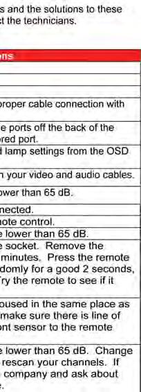
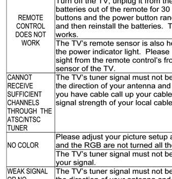
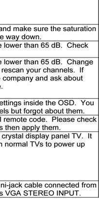
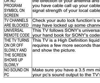
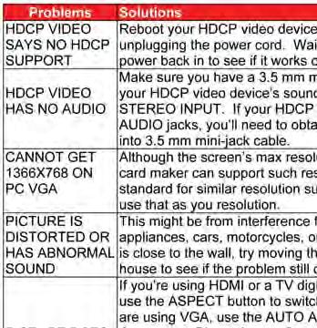
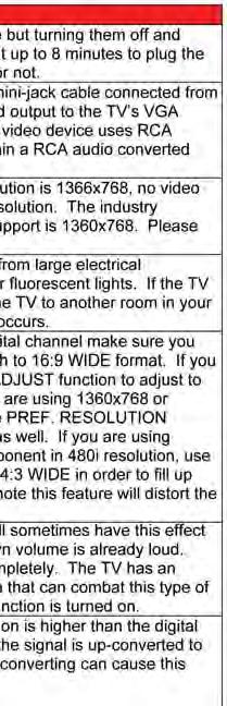
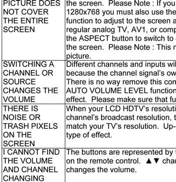
33 Trouble Shooting SunBriteTV Model 5510HD Operator s Manual Page 33


34 Care of SunBriteTV Important Information About the Anti-Reflective Window on your SunBriteTV Outdoor Television The anti-reflective window on your all-weather TV is designed to dramatically reduce reflection and improve the contrast of the image on your TV. In order to preserve the anti-reflective properties of the window, it is imperative that you follow the maintenance guidelines below: 1. Clean the window by using the following directions: To clean the SunBriteTV window, use glass cleaner and a lint-free or micro-fiber cloth. Spray the solution on the cloth and then apply to the window. DO NOT use acrylic cleaners. 2. When the TV is not in use, keep it covered with the SunBriteTV Outdoor Dust Cover The fitted dust cover is constructed with weatherproof 4-ply polypropylene UV protection fabric that protects the window from direct and indirect sunlight, and keeps wind-blown objects from scratching the surface of the window. To order the Dust Cover, contact your Authorized SunBriteTV dealer or SunBriteTV s Customer Service at General Cleaning Remove any dirt and salt deposits from the unit, being careful to rinse the cloth frequently to avoid scratching the TV or screen surface. Avoid using harsh chemicals, abrasives, or solvents when cleaning any surface on the unit. Snow and Ice Use a soft brush and towel to remove snow and ice from the unit. Fiber Filter The Fiber Filter is located on the back of the unit, inside the Intake Vent at the top of the TV (Figure 1). In areas where dust or salt air is prevalent, it is recommended that the Fiber Filter be cleaned regularly. 1. Release the Fiber Filter by pulling it out from the corner of the Intake Vent (Figure 2). Notice how the Fiber Filter fits in the upper and lower channels, and tightly against the angled corners (Figure 3). 2. Pull the Fiber filter out of the TV, and wash it with mild detergent and warm water. After rinsing, let the Fiber Filter dry completely. 3. Put the Fiber Filter back up into the Intake Vent pushing the filter first into the upper channel, then fit it into the lower channel. Make sure filter fits tightly against angled corners at each end of the Intake Vent. (Figure 4). Figure 1 Intake Vent Figure 2 Intake Vent Fiber Filter Fiber Filter Figure 4 Figure 3 Upper Channel Angled Corner Lower Channel Angled Corner Page 34


35 Specifications Specifications for SunBriteTV Model 5510HD Specifications LCD Screen 55-inch diagonal TFT Active Matrix Resolution 1920 x 1080 full-hd 1080p, 120 Hz Frame Rate Aspect Ratio 16:9 Contrast Ratio 5000:1 Viewing Angle 176 o Response Time 6.5 milliseconds TV formats 1080p, 1080i, 720p, 480p, 480i Input Connectors: RF Antenna/CATV (ATSC/QAM/NTSC) x1 HDMI HDMI Input x2 Video Component PC YPbPr plus Stereo Audio x2 15-pin D-sub VGA plus Stereo Audio Control Set RS232 Serial, Discrete IR Control, Concealed IR Window Audio Out SPDIF, Analog 1/8 stereo mini jack Speakers 10-watt x 2 channels, water-resistant detachable speaker module Exterior Powder-coated aluminum Input Power VAC, Hz 4.0 A Max Operating Temp. -24 o to 122 o F. (-31 o to 50 o C.) * Non-op. Temp. (Off-mode with power applied) Accessories Included TV Dimensions Weight Warranty -24 o to 140 o F. (-31 o to 60 o C.) The non-operating temperature feature requires power to be applied Water-resistant remote control W x H (33.13 H with speakers) x 7.80 D 90.0 lbs; 95 lbs with speakers One-year, in-factory, parts and labor Front View Dimensions with detachable speaker module. All measurements are in inches Side View Specifi cations are subject to change. *Temperature range is for operation in shaded location. PC Timing Codes SunBriteTV Model 5510HD Operator s Manual Page 35
36 Features Information and Instructions Internal Thermostatically-Controlled Heater The Internal Thermostatically-Controlled Heater keeps the unit warm in freezing temperatures and activates automatically when the SunBriteTV internal temperature sensor reads a temperature inside the unit of 32 O F. or lower. The heater remains on until the internal temperature rises to at least 42 O F. The heater provides a 20 O F. temperature rise, allowing the TV to safely remain in temperatures as low as -24 O F. The ventilation fans are not activated when the heater is running and will automatically activate when required. If temperatures below -24 O F. are expected, we recommend that you bring your SunBriteTV inside to prevent damage to the LCD screen. Note: In order for the automatic heater to work properly, your SunBriteTV must have power applied at all times. Programming Other Manufacturers Universal Remote Control Devices When programming a DirectTV, local cable universal remote control or Control system, you may find that SunBriteTV may not be on the list of TV manufacturers. If that is the case, Model 5510HD supports SONY s universal remote code. SunBriteTV Pixel Quality Policy SunBriteTV s Pixel Quality Policy (Applicable to LCD TVs sold within USA and Canada only.) SunBriteTV TM LCD screens are manufactured with rigorous standards to maintain optimal viewing. However, the LCD screen may have minor defects that appear as a small bright or dark pixel. This is common to all LCD screens used in display and television products, and is not specific to SunBriteTV. Bright dots are dots that appear bright and unchanged in size when a LCD TV screen displays a black pattern. Dark dots are dots that appear dark and unchanged in size when a LCD TV screen displays a pure red, green, or blue pattern. Adjacent dots are pixels located directly next to each other. Your SunBriteTV will be replaced under warranty if it meets one of the following criteria: A total of 7 defective pixels, including both bright dots and dark dots are present. (Model 5510HD LCD TV screen has over a million pixels.) 2 or more pairs of adjacent bright dots are present. 3 adjacent bright dots are present. 3 adjacent dark dots are present. To locate defective pixels, the LCD panel should be examined under normal operating conditions, in its native display resolution, with a 90 degree viewing angle, from a distance of a approximately 20 inches. To qualify for replacement, a defective LCD screen must be reported to SunBriteTV within 14 days from the day the customer receives the TV. For questions, please call our toll-free service number at Page 36


37 Appendix A - RS232 Control Codes SunBriteTV Model 5510HD Operator s Manual Page 37
38 6 1 Appendix B - RS232 Control Cable Pinout DB9F, Typical PC Serial / Control System RS232 port. 1 1/8" Stereo Plug 5 Com Specs: 9600 baud 8 data, 1 stop, no parity Ground Rx Data From control system Tx Data to control system SunbriteTV RS232 Control Cable July Preliminary SIZE FSCM NO DWG NO REV A1 SCALE SHEET 1 OF 1 Page 38
39 This page is intentionally left blank.

40
Operator s Manual Model SB-3211HD
 Operator s Manual Model SB-3211HD Revision 339-161104 PN: M32-010-00 Important Safety Instructions Dear SunBriteTV Customer: Congratulations on the ownership of your SunBriteTV all-weather outdoor LCD
All-Weather Outdoor LCD Television. Operator s Manual. Model 3220HD. Revision 3220HD-Rev PN: M
 All-Weather Outdoor LCD Television Operator s Manual Model 3220HD Revision 3220HD-Rev-318-120801 PN: M32-002-02 Important Safety Instructions Dear SunBriteTV Customer: Congratulations on the ownership
All-Weather Outdoor LCD Television. Operator s Manual. Model SB-5507EST-L. Model SB-5507EST-P. Rev. 5507EST-Rev PN: M
 All-Weather Outdoor LCD Television Operator s Manual Model SB-5507EST-L Model SB-5507EST-P Rev. 5507EST-Rev 120828 PN: M55-004-00 Important Safety Instructions Dear SunBriteTV Customer: Congratulations
Operator s Manual Model SB-5570HD Model SB-6570HD
 Operator s Manual Model SB-5570HD Model SB-6570HD Revision 339-140617 PN: M55-065-00 Important Safety Instructions Dear SunBriteTV Customer: Congratulations on the ownership of your SunBriteTV all-weather
Evolution Digital HD Set-Top Box Important Safety Instructions
 Evolution Digital HD Set-Top Box Important Safety Instructions 1. Read these instructions. 2. Keep these instructions. 3. Heed all warnings. 4. Follow all instructions. 5. Do not use this apparatus near
HD Digital Set-Top Box Quick Start Guide
 HD Digital Set-Top Box Quick Start Guide Eagle Communications HD Digital Set-Top Box Important Safety Instructions WARNING TO REDUCE THE RISK OF FIRE OR ELECTRIC SHOCK, DO NOT EXPOSE THIS PRODUCT TO RAIN
CAUTION RISK OF ELECTRIC SHOCK NO NOT OPEN
 Evolution Digital HD Set-Top Box Important Safety Instructions 1. Read these instructions. 2. Keep these instructions. 3. Heed all warnings. 4. Follow all instructions. 5. Do not use this apparatus near
Introduction. Important Safety Instructions
 Introduction Congratulations on purchasing your Eviant Portable Digital TV. On June 12, 2009 the conversion to digital television broadcasting will be complete all throughout the United States and Puerto
Veranda 4K Operator s Manual. Models: SB-4374UHD-BL SB-5574UHD-BL SB-6574UHD-BL SB-7574UHD-BL. MVE Revision _1035
 Veranda 4K Operator s Manual Models: SB-4374UHD-BL SB-5574UHD-BL SB-6574UHD-BL SB-7574UHD-BL MVE-002-00 Revision 171129_1035 Important Safety Instructions Dear SunBriteTV Customer: Congratulations on the
2.0 Wall Mount TV Soundbar Instruction Manual
 8010275 2.0 Wall Mount TV Soundbar Instruction Manual Read all of the instructions before using this soundbar and keep the manual in a safe place for future reference. Safety Information CA UT IO N RISK
ATTACHING & REMOVING THE BASE
 TV53DB ATTACHING & REMOVING THE BASE 1. To install or remove the neck, screw in or remove the 4 screws indicated in the picture. 2. To install the base, place the display unit flat on a table. Afterwards
Congratulations on purchasing your Eviant Portable Digital TV.
 Introduction Congratulations on purchasing your Eviant Portable Digital TV. On June 12, 2009 the conversion to digital television broadcasting will be complete all throughout the United States and Puerto
55" Curved Ultra HD LED TV User s Guide for Model TU5587B v For the most up-to-date version of this User s Guide, go to
 55" Curved Ultra HD LED TV User s Guide for Model TU5587B v1922-01 For the most up-to-date version of this User s Guide, go to www.gpx.com Safety Instructions & Warnings CAUTION RISK OF ELECTRIC SHOCK
Acer LCD TV AT2001 User's Guide
 Acer LCD TV AT2001 User's Guide Copyright 2005. Acer Incorporated. All Rights Reserved. Acer AT2001 User' s Guide Original Issue: May 2005 Acer and the Acer logo are registered trademarks of Acer Incorporated.
SCEPTRE X23 HDTV User Manual
 Dear Sceptre Customer, Congratulations on your new SCEPTRE X23 High Definition LCD Television purchase. Thank you for your support. To ensure safety and many years of trouble free operation of your TV,
 Register your product and get support at www.philips.com/welcome SWS3435S/27 SWS3435H/37 EN User manual Contents 1 Important 4 Safety 4 English 2 Your SWS3435 6 Overview 6 3 Installation 7 Connect the
USER MANUAL. 27 Full HD Widescreen LED Monitor L27ADS
 USER MANUAL 27 Full HD Widescreen LED Monitor L27ADS TABLE OF CONTENTS 1 Getting Started 2 Control Panel/ Back Panel 3 On Screen Display 4 Technical Specs 5 Care & Maintenance 6 Troubleshooting 7 Safety
USER MANUAL. 22" Class Slim HD Widescreen Monitor L215DS
 USER MANUAL 22" Class Slim HD Widescreen Monitor L215DS TABLE OF CONTENTS 1 Getting Started Package Includes Installation 2 Control Panel / Back Panel Control Panel Back Panel 3 On Screen Display 4 Technical
LCD VALUE SERIES (32 inches)
") LCD VALUE SERIES (32 inches) http://www.orionimages.com All contents of this document may change without prior notice, and actual product appearance may differ from that depicted herein 1. SAFETY INSTRUCTION
LCD VALUE SERIES (32 inches) http://www.orionimages.com All contents of this document may change without prior notice, and actual product appearance may differ from that depicted herein 1. SAFETY INSTRUCTION
E325 Series User Guide
 E325 Series User Guide PACKAGE CONTENTS SCEPTRE Display x 1 Display Base x 1 Thick Threaded Screws x 3 Thin Threaded Screws x 4 Circular Metal Plate x 1 Black Plastic Ring x 1 Power Cord x 1 (Attached)
E246 Series User Guide
 E246 Series User Guide PACKAGE CONTENTS SCEPTRE Display x 1 Display Base x 1 Display Neck x 1 Screws x 6 (ST3 x 10mm) Warranty Card x 1 Power Cord x 1 (Attached) Display Remote Control (AAA Batteries included)
HD Digital MPEG2 Encoder / QAM Modulator
 HD Digital MPEG2 Encoder / QAM Modulator HDMI In QAM Out series Get Going Guide ZvPro 800 Series is a one or two-channel unencrypted HDMI-to-QAM MPEG 2 Encoder / QAM Modulator, all in a compact package
Register your product and get support at SDV5122/27. EN User manual
 Register your product and get support at www.philips.com/welcome SDV5122/27 User manual Contents 1 Important 4 Safety 4 Notice for USA 5 Notice for Canada 5 Recycling 6 English 2 Your SDV5122 7 Overview
HD Digital MPEG2 Encoder / QAM Modulator
 HD Digital MPEG2 Encoder / QAM Modulator YPrPb VGA In QAM Out series Get Going Guide ZvPro 600 Series is a one or two-channel Component or VGA-to-QAM MPEG 2 Encoder/ Modulator, all in a compact package
ZvBox 150. HD video distribution over COAX Get Going Guide
 ZvBox 150 HD video distribution over COAX Get Going Guide ZvBox 150 is an HD MPEG 2 Encoder and frequency agile QAM Modulator. It allows you to convert any HD video source, Component or RGB (VGA), in real
HD Digital MPEG2 Encoder / QAM Modulator Get Going Guide
 series HD Digital MPEG2 Encoder / QAM Modulator Get Going Guide HDb2640 HDb2620 HDb2540 HDb2520 The HDbridge 2000 Series is a combination HD MPEG 2 Encoder and frequency-agile QAM Modulator, all in a 1RU
39 WIDESCREEN LED TV MODEL NO.: SP-LED40 USER MANUAL
 39 WIDESCREEN LED TV MODEL NO.: SP-LED40 USER MANUAL Please read this manual carefully before using, and keep it for future reference. IMPORTANT SAFETY INSTRUCTIONS 1. Read these instructions All the safety
PLL1920M LED LCD Monitor
 PLL1920M LED LCD Monitor USER'S GUIDE www.planar.com Content Operation Instructions...1 Safety Precautions...2 First Setup...3 Front View of the Product...4 Rear View of the Product...5 Installation...6
16 WIDESCREEN LED TV MODEL NO.: SP-LED16 USER MANUAL
 16 WIDESCREEN LED TV MODEL NO.: SP-LED16 USER MANUAL Please read this manual carefully before using, and keep it for future reference. IMPORTANT SAFETY INSTRUCTIONS 1. Read these instructions All the safety
E405 Series User Guide
 PACKAGE CONTENTS E405 Series User Guide SCEPTRE Display x 1 Display Base x 1 Display Neck Thick Threaded Screws (ST4x14mm) x 4 Plastic Ring x 1 Metal Plate x 1 Warranty Card x 1 Display Remote Control
Programming Manual for Broadcastvision Entertainment
 Programming Manual for Broadcastvision Entertainment 18.5 Widescreen LCD Part Number: AXS19HD2G 18.5 Widescreen Controller Part Number: AXSPVSC-BVE AXS19HD2G AXSPVSC-BVE Other parts and accessories included
28 4K LED monitor. User Manual M284K
 28 4K LED monitor User Manual M284K CONTENTS Safety Information... 2 What s included..... 4 Getting Started....... 8 Troubleshooting.... 14 Specification.... 15 2 of 15 SAFETY INFORMATION Read these instructions
U65 Series User Guide
 U65 Series User Guide IMPORTANT SAFETY INSTRUCTIONS Electricity is used to perform many useful functions, but it can also cause personal injuries and property damage if improperly handled. This product
15 LCD Television FLM-1512
 15 LCD Television FLM-1512 20060216 1 Polaroid. Add a little color to your life. Since 1937, America has turned to Polaroid for their photography needs. Today, families look to Polaroid for consumer electronics
AUTO - SCANNING WITH DIGITAL CONTROL LCD COLOR MONITOR FS-L1903C. User manual (Rev.01) SMITHS HEIMANN
 SMITHS HEIMANN") AUTO - SCANNING WITH DIGITAL CONTROL LCD COLOR MONITOR FS-L1903C User manual (Rev.01) SMITHS HEIMANN www.smithsdetection.com Table of Contents Safety Instructions... 5 Accessories... 8 Power Connections...
AUTO - SCANNING WITH DIGITAL CONTROL LCD COLOR MONITOR FS-L1903C User manual (Rev.01) SMITHS HEIMANN www.smithsdetection.com Table of Contents Safety Instructions... 5 Accessories... 8 Power Connections...
E246 Series User Guide
 E246 Series User Guide IMPORTANT SAFETY INSTRUCTIONS Electricity is used to perform many useful functions, but it can also cause personal injuries and property damage if improperly handled. This product
PLL2210MW LED Monitor
 PLL2210MW LED Monitor USER'S GUIDE www.planar.com Content Operation Instructions...1 Safety Precautions...2 First Setup...3 Front View of the Product...4 Rear View of the Product...5 Quick Installation...6
PL2410W LCD Monitor USER'S GUIDE.
 PL2410W LCD Monitor USER'S GUIDE www.planar.com Content Operation Instructions...1 Safety Precautions...2 First Setup...3 Front View of the Product...4 Rear View of the Product...5 Quick Installation...6
27'' Full HD LED Monitor KALED27MONSC Quick Start Guide
 Safety Warnings 27'' Full HD LED Monitor KALED27MONSC Quick Start Guide TO REDUCE THE RISK OF ELECTRIC SHOCK, DO NOT REMOVE ANY COVERS (OR BACKINGS). NO USER SERVICEABLE PARTS ARE INSIDE. REFER ALL SERVICING
USER MANUAL. 27 Full HD Widescreen LED Monitor L270E
 USER MANUAL 27 Full HD Widescreen LED Monitor L270E TABLE OF CONTENTS 1 Getting Started 2 Control Panel/ Back Panel 3 On Screen Display 4 Technical Specs 5 Care & Maintenance 6 Troubleshooting 7 Safety
USER MANUAL Full HD Widescreen LED Monitor L215ADS
 USER MANUAL 21.5 Full HD Widescreen LED Monitor L215ADS TABLE OF CONTENTS 1 Getting Started 2 Control Panel/ Back Panel 3 On Screen Display 4 Technical Specs 5 Care & Maintenance 6 Troubleshooting 7 Safety
SAFETY WARNINGS AND GUIDELINES
 SAFETY WARNINGS AND GUIDELINES Please read this manual thoroughly, paying extra attention to these safety warnings and guidelines: Do not expose this monitor to water or moisture of any kind. Do not handle
USER MANUAL Full HD Widescreen LED Monitor L215IPS
 USER MANUAL 21.5 Full HD Widescreen LED Monitor L215IPS TABLE OF CONTENTS 1 Getting Started 2 Control Panel/ Back Panel 3 On Screen Display 4 Technical Specs 5 Care & Maintenance 6 Troubleshooting 7 Safety
39" 1080p LCD Television PLCD3992A
 PROSCAN 39" 1080p LCD Television PLCD3992A Contents Contents Caution Safety Information Unit and Accessories Product Feature 2 3 4 4 Introduction 5-9 1. Front View 5 2. Rear View 6 3. Instruction for
PXL2760MW LED LCD Monitor
 PXL2760MW LED LCD Monitor USER'S GUIDE www.planar.com Content Operation Instructions...1 Safety Precautions...2 Package Overview...3 First Setup...4 Front View of the Product...5 Rear View of the Product...6
17 19 PROFESSIONAL LCD COLOUR MONITOR ART
 17 19 PROFESSIONAL LCD COLOUR MONITOR ART. 41657-41659 Via Don Arrigoni, 5 24020 Rovetta S. Lorenzo (Bergamo) http://www.comelit.eu e-mail:export.department@comelit.it WARNING: TO REDUCE THE RISK OF FIRE
Winmate Communication INC.
 20.1 Military Grade Display Model: R20L100-RKA2ML User s Manual Winmate Communication INC. May, 2011 1 IMPORTANT SAFETY INSTRUCTIONS Please read these instructions carefully before using the product and
For technical assistance, please call and select option 3 or our tech support group at
 Dear Sceptre Customer, Congratulations on your new SCEPTRE X40 High Definition LCD Television purchase. Thank you for your support. To ensure safety and many years of trouble free operation of your TV,
OWNER'S MANUAL MODEL: DTV-2000 STANDBY/ON
 OWNER'S MANUAL MODEL: DTV-2000 STANDBY/ON CH+ CH- TABLE OF CONTENTS SAFETY PRECAUTIONS IMPORTANT SAFETY INSTRUCTIONS and FEATURES ACCESSORIES and LOADING BATTERIES REMOTE CONTROL UNIT FRONT PANEL and REAR
X50 Series User Guide
 X50 Series User Guide IMPORTANT SAFETY INSTRUCTIONS Electricity is used to perform many useful functions, but it can also cause personal injuries and property damage if improperly handled. This product
USER MANUAL Full HD Widescreen LED Monitor L236VA
 USER MANUAL 23.6 Full HD Widescreen LED Monitor L236VA TABLE OF CONTENTS 1 Getting Started 2 Control Panel/ Back Panel 3 On Screen Display 4 Technical Specs 5 Care & Maintenance 6 Troubleshooting 7 Safety
TFT LCD MONITOR USER MANUAL. L80AP and L101AP
 TFT LCD MONITOR USER MANUAL L80AP - 8.0 and L101AP - 10.1 Table Of Contents Table of contents/ Warning.... 2 Precautions...3 About this user manual and products / Items included in the delivery..... 4
ACUBRITE 23 SS. Manual. Stainless Steel Chassis 23" LCD Display. Content
 ACUBRITE 23 SS Stainless Steel Chassis 23" LCD Display Manual Introduction... 2 Hardware Installation... 2 The Display Timing... 5 The Display Outline Dimensions... 6 The Display Controls... 7 The Screen
USER MANUAL. 28" 4K Ultra HD Monitor L28TN4K
 USER MANUAL 28" 4K Ultra HD Monitor L28TN4K TABLE OF CONTENTS 1 Getting Started 2 Control Panel/ Back Panel 3 On Screen Display 4 Technical Specs 5 Care & Maintenance 6 Troubleshooting 7 Safety Info &
2.4 GHz WIRELESS VIDEO SENDER SYSTEM MODEL: VS6234
 2.4 GHz WIRELESS VIDEO SENDER SYSTEM MODEL: VS6234 Please read this manual thoroughly before operating this system OPERATING INSTRUCTIONS 03/02 1 SAFETY INSTRUCTIONS CAUTION! RISK OF ELECTRIC SHOCK. DO
PLL2710W LED LCD Monitor
 PLL2710W LED LCD Monitor USER'S GUIDE www.planar.com Content Operation Instructions...1 Safety Precautions...2 Package Overview...3 First Setup...4 Front View of the Product...5 Rear View of the Product...6
17 /19. User's Manual
 17 /19 Color TFT LCD Monitor User's Manual Version: 03 * All other brand names are registered trademarks of their respective owners Table of Contents Important Safety Instructions FCC Regulation Class
4 PORT HDMI SWITCH
 4 PORT HDMI SWITCH 1518896 IMPORTANT SAFEGUARDS OF HDMI SWITCH PRODUCTS PLEASE READ CAREFULLY THE FOLLOWING SAFEGUARDS THAT ARE APPLICABLE TO YOUR EQUIPMENT 1. Read instructions - All the safety and operating
Contents. Safety and Warnings Introduction...4. Installation Remote Control...9. Operation
 41 Contents Safety and Warnings...2-3 Introduction...4 Installation...5-8 Remote Control...9 Operation...10-13 -1- IMPORTANT SAFETY INSTRUCTION 1) Read these instructions. 2) Keep these instructions. 3)
LED TV MODEL NO.: NE22K5BG. Please read this manual carefully before installing and operating the TV. Keep this manual handy for further reference
 LED TV USER MANUAL MODEL NO.: NE22K5BG IMPORTANT Please read this manual carefully before installing and operating the TV. Keep this manual handy for further reference Table Of Contents Preparations Guide
Full High Definition LCD TV USER MANUAL
 1080p3 LCD TV Full High Definition LCD TV 1080p3 USER MANUAL Important Safety Precautions Important Safety Precautions 1 CAUTION RISK OF ELECTRIC SHOCK DO NOT OPEN This symbol indicates important instructions
ZVOX AccuVoice TV Speaker Model AV203
 ZVOX AccuVoice TV Speaker Model AV203 SETUP & OPERATION www.zvoxaudio.com READ THIS FIRST Important Safety Instructions For ZVOX Audio System WARNING TO PREVENT FIRE OR SHOCK HAZARD, DO NOT EXPOSE THIS
User Guide. 42" LED-LCD, 60Hz 1080p NS-42E760A12
 User Guide 42" LED-LCD, 6Hz 18p NS-42E76A12 Contents CHILD SAFETY...................................................1 Important safety instructions.....................................2 Warnings........................................................
 Register your product and get support at www.philips.com/welcome SWW1810 User manual 3 Contents 1 Important 4 Safety 4 English 2 Your Wireless HD AV Connect 6 What is in the box 6 3 Overview 7 The transmitter
USER MANUAL. 27" 2K QHD LED Monitor L27HAS2K
 USER MANUAL 27" 2K QHD LED Monitor L27HAS2K TABLE OF CONTENTS 1 Getting Started 2 Control Panel/ Back Panel 3 On Screen Display 4 Technical Specs 5 Troubleshooting 6 Safety Info & FCC warning 1 GETTING
23 LED Television TLAE-02319
 Instruction Manual 23 LED Television TLAE-02319 Contents Caution Safety Information Accessories Technical Specification Product Introduction Front View Rear View Connections Remote Control Basic Operation
ZVOX AccuVoice TV Speaker Model AV203
 ZVOX AccuVoice TV Speaker Model AV203 SETUP & OPERATION www.zvoxaudio.com 2 ZVOX AccuVoice TV Speaker Setup & Operation READ THIS FIRST Important Safety Instructions For ZVOX Audio System WARNING TO PREVENT
10.4" LCD Monitor with Aluminum Front Bezel YPM1040PHB
 SPECIFICATION FOR APPROVAL M0DEL: 10.4" LCD Monitor with Aluminum Front Bezel YPM1040PHB BASE MODEL Customer's Confirmation Approved by: Reviewed by: Prepared by: Supplier's Confirmation Approved by: Reviewed
17" & 19" Color TFT LCD Monitor
 17" & 19" Color TFT LCD Monitor KMC-17B & KMC-19B User's Manual for Operation and installation Screen Size : KMC-17B (17" inch TFT LCD) KMC-19B (19" inch TFT LCD) Display Size : KMC-17B (337.920mm X 270.336mm)
Q-TV2. User Manual. for Screens
 Q-TV2 User Manual for 30-42 Screens Contents Introduction 02 Safety Guidelines 03 Getting started 03 Potential Uses 04 Carton Contents 05 Q-TV2 Controls 05 Remote Fixings 06 Fixing Rails 07 Fitting Q-TV2
DCL9AW. User Manual. English
 DCL9AW User Manual English PRECAUTIONS Information for users applicable in European Union countries 1 Information for users applicable in United States of America 1 Installation 1 Power connection 1 Maintenance
Instruction Guide. The TV Jockey Computer Monitor TV Tuner with Remote COMP2VGATVGB. The Professionals Source For Hard-to-Find Computer Parts
 VIDEO ADAPTER The TV Jockey Computer Monitor TV Tuner with Remote COMP2VGATVGB Instruction Guide * Actual product may vary from photo The Professionals Source For Hard-to-Find Computer Parts FCC COMPLIANCE
Technical Specifications
 INSTALLATION SHEET AND OPERATORS MANUAL General Description: The is a mixer/preamplifier that includes 6 channels that each include a microphone input at screw terminals and an aux input at an RCA jack.
By CHANNEL VISION. Flush Mount Amplifier A0350
 Spkrs Local In IR In 24VDC A0350 10 The A0350 can be used with Channel Vision s CAT5 audio hubs to provide a powerful 50Watts per channel in the listening zone. Alternatively, the A0350 can be added to
Quick Start Guide. Digital Research Technologies Inc. 4 Marconi, Irvine, CA For: DLCD26, DLCD32, DLCD42 & DLCD42P LCD Televisions
 Quick Start Guide Digital Research Technologies Inc. 4 Marconi, Irvine, CA 92618 For: DLCD26, DLCD32, DLCD42 & DLCD42P LCD Televisions 1 Distance recommendations: Always position the LCD TV set where sufficient
USER MANUAL. For: DLCD26, DLCD32, DLCD42 & DLCD42P LCD Televisions
 USER MANUAL For: DLCD26, DLCD32, DLCD42 & DLCD42P LCD Televisions BEFORE USING THIS PRODUCT... 2 COMMUNICATION REGULATION... 2 IMPORTANT SAFETY INSTRUCTIONS... 3 SAFETY INFORMATION... 4 MAINTENANCE AND
DM-1CH SD DVB-T MODULATOR INSTRUCTION MANUAL
 DM-1CH SD DVB-T MODULATOR INSTRUCTION MANUAL 2. Caution Statements and Table of Contents Table of Contents 2. Caution Statements and Table of contents 3. Important Safety Instructions 4. Important Safety
USER S Manual NGLT104WPD NGLT150WPD LCD TV / Monitor (IP67 Grade)
") USER S Manual NGLT104WPD NGLT150WPD LCD TV / Monitor (IP67 Grade) This Manual is revisable without further notice Contents CONTENTS ------------------------------------------------------------------- 1
USER S Manual NGLT104WPD NGLT150WPD LCD TV / Monitor (IP67 Grade) This Manual is revisable without further notice Contents CONTENTS ------------------------------------------------------------------- 1
User Manual High Definition Digital Set Top Box DVBT9070 Please read this User Manual carefully to ensure proper use of this product and keep this man
 User Manual High Definition Digital Set Top Box DVBT9070 Please read this User Manual carefully to ensure proper use of this product and keep this manual for future reference. Important Safety Instructions
PXL2470MW LED LCD Monitor
 PXL2470MW LED LCD Monitor USER'S GUIDE www.planar.com Content Operation Instructions...1 Unpacking Instructions...2 Safety Precautions...2 Package Overview...3 First Setup...4 Front View of the Product...5
USER S MANUAL MANUEL DE L UTILISATEUR MANUAL DEL USUARIO EW39T4LZ
 USER S MANUAL MANUEL DE L UTILISATEUR MANUAL DEL USUARIO EW39T4LZ Contents Contents Caution Safety Information Unit and Accessories Product Feature 2 3 4 4 Introduction 5-9 1. Front View 5 2. Rear View
19 / 20.1 / 22 WIDE SCREEN TFT-LCD MONITOR
 19 / 20.1 / 22 WIDE SCREEN TFT-LCD MONITOR V193/ V220 Series V202 Series USER MANUAL www.viewera.com Rev. 2.0 Table of Contents EMC Compliance......1 Important Precautions...2 1. Package contents....3
CONTENTS 8 ACCESSORIES 13 9 TROUBLE SHOOTING AND ADVICE SPECIFICATIONS BATTERY USAGE CAUTION 13
 CONTENTS 1 PREFACE 2 2 SAFETY PRECAUTIONS 2 3 FRONT & BACK VIEW, REAR CONNECTION OF LCD 3 4 TV INSTALLATION DRAWINGS 4 4.1 ANTENNA CONNECTION 4 4.2 AV1 INPUT CONNECTION 4 4.3 AV2 INPUT CONNECTION 4 4.4
Monitor Display and Media Box...3 Media Box Front Panel...4 Media Box Back Panel...5 Using the Monitor s Inputs...7 Using the Remote Control...
 fety Table of Contents Safety...iii Introduction...1 Monitor Description...3 Monitor Display and Media Box...3 Media Box Front Panel...4 Media Box Back Panel...5 Using the Monitor s Inputs...7 Using the
WS55 INSTRUCTION MANUAL
 WS55 INSTRUCTION MANUAL WIRELESS HD CONTENT WHAT'S INCLUDED... 3 OVERVIEW... 3 INSTALLATION... 4 LED BEHAVIOR...7 WALL MOUNTING... 9 TROUBLESHOOTING...10 SPECIFICATIONS... 13 FCC STATEMENT...14 IC STATEMENT...14
PowerWave PW1A Panel and Wall-Mount Models Installation Guide AV69006-XXX
 PowerWave PW1A Panel and Wall-Mount Models Installation Guide 8820-00063 AV69006-XXX Table of Contents Table of Contents sections 1 2 3 4 5 6 7 8 9 1. Introduction............................................
CONTENTS. Names of each part(front View) / Accessories 6. Names of each part(back View) 7. Mounting on a Desktop / Installation Precautions
 / Accessories 6. Names of each part(back View) 7. Mounting on a Desktop / Installation Precautions") JE208WV CONTENTS Safety Precautions Important Information 3 Important Safeguards 4~5 User Guidance Information Names of each part(front View) / Accessories Names of each part(back View) 7 Mounting on a
JE208WV CONTENTS Safety Precautions Important Information 3 Important Safeguards 4~5 User Guidance Information Names of each part(front View) / Accessories Names of each part(back View) 7 Mounting on a
VIZIO. QUICK START GUIDE Model: E390-B1
 VIZIO QUICK START GUIDE Model: E390-B1 IMPORTANT SAFETY INSTRUCTIONS Your TV is designed and manufactured to operate within defined design limits. Misuse may result in electric shock or fire. To prevent
ZVOX AccuVoice TV Speaker MODEL AV150.
 ZVOX AccuVoice TV Speaker MODEL AV150 www.zvoxaudio.com READ THIS FIRST Important Safety Instructions For ZVOX Audio System WARNING TO PREVENT FIRE OR SHOCK HAZARD, DO NOT EXPOSE THIS APPLIANCE TO RAIN
Hi-Vision TV Box. High Resolution TV BOX with PIP feature Model:174190
 Operational Manual Hi-Vision TV Box High Resolution TV BOX with PIP feature Model:174190 Thanks for your purchasing this product. Please read the Manual carefully before using it, and keep this manual
VIZIO. QUICK START GUIDE Model: E500i-B1E
 VIZIO QUICK START GUIDE Model: E500i-B1E IMPORTANT SAFETY INSTRUCTIONS Your TV is designed and manufactured to operate within defined design limits. Misuse may result in electric shock or fire. To prevent
Operating Instructions
 Operating Instructions SDI Input board Model No. AV-HS04M1 РУССКИЙ FRANÇAIS DEUTSCH ENGLISH ESPAÑOL ITALIANO Before operating this product, please read the instructions carefully and save this manual for
Find Inside: Connections... page 5. MultiTask Audio... page 17. Menus... page 18. Troubleshooting... page 24. rca.com
 Changing Entertainment. Again. LCD User s Guide Find Inside: Connections... page 5 MultiTask Audio... page 17 Menus... page 18 Troubleshooting... page 24 rca.com Important Information CAUTION RISK OF ELECTRIC
E32 Series User Guide
 PACKAGE CONTENTS E32 Series User Guide SCEPTRE Display x 1 TV Foot x 2 Screws x 4 Power Cord x 1 (attached) Warranty Card x 1 Display Remote Control (AAA Batteries included) x 1 User Guide x 1 (Complete
For technical assistance, please call and select option 3 or our tech support group at
 Dear Sceptre Customer, Congratulations on your new environmentally friendly SCEPTRE X320 High Definition LCD Television purchase. Thank you for your support. To ensure safety and many years of trouble
42" 47" 55" 42.1, 47.1, 55.1 STORM. Outdoor Television USER MANUAL. Serial No:
 42" 47" 55" 42.1, 47.1, 55.1 STORM Outdoor Television USER MANUAL Serial No: www.seura.com Thank you for selecting Séura s Storm Outdoor Television. This product has been inspected and packaged carefully
Disclaimer. Trademarks. Copyright. Contact Us Control4 Corporation S. Election Road Salt Lake City, UT USA
 Disclaimer Trademarks Copyright Control4 makes no representations or warranties with respect to this publication, and specifically disclaims any express or implied warranties of merchantability or fitness
User Guide 26" LED TV NS-26E340A13
 User Guide 26" LED TV NS-26E340A13 Contents CHILD SAFETY...................................................1 Important Safety Instructions.....................................2 WARNING.......................................................
IMPORTANT SAFETY INSTRUCTIONS
 IMPORTANT SAFETY INSTRUCTIONS 1. Read, follow and keep these instructions safely. 2. Heed all warnings. 1. Do not use this apparatus near water. 2. Clean only with dry cloth. 3. Do not block any ventilation
Wireless 4 Channel Receiver with 2 Night Vision cameras
 Wireless 4 Channel Receiver with 2 Night Vision cameras Instruction Manual English Version 2.0 MODEL: SHS-4WLS www.lorexcctv.com Copyright 2006 LOREX Technology Inc. Thank you for purchasing the SHS-4WLS.