B264 opengear Encoder B264 Standalone Encoder. User Manual. Version 3.0
|
|
|
- Denis Pierce
- 5 years ago
- Views:
Transcription

1 Niagara Video B264 opengear Encoder B264 Standalone Encoder User Manual Version 3.0
2 Copyright 2016 Niagara Video Corporation. All rights reserved. Contents of this publication may not be reproduced in any form without the written permission of Niagara Video. Notice The material in this manual is furnished for informational use only, and it is subject to change without notice. It must not be construed as a commitment by Niagara Video. Niagara Video assumes no responsibility or liability for errors or inaccuracies that may appear in this manual. Trademarks DashBoard Control System is a trademark of Ross Video Limited. opengear is a trademark of Ross Video Limited. Apple Mac OS, Leopard, and Snow Leopard are trademarks of Apple Computer, Inc., registered in the U.S. and other countries. Microsoft, Internet Explorer, and Windows are either registered trademarks or trademarks of Microsoft Corporation in the U.S.A. and/or other countries. Linux is the registered trademark of Linus Torvalds in the U.S. and other countries. Flash is the registered trademark of Adobe in the US and other countries. All other product names and any registered and unregistered trademarks mentioned in this guide are used for identification purposes only and remain the exclusive property of their respective owners. Environmental Information The equipment that you purchased required the extraction and use of natural resources for its production. It may contain hazardous substances that could impact health and the environment. To avoid the potential release of those substances into the environment and to diminish the need for the extraction of natural resources, Niagara Video encourages you to use the appropriate take-back systems. These systems will reuse or recycle most of the materials from your end-oflife equipment in an environmentally friendly and health conscious manner. If you need more information on the collection, reuse, and recycling systems, please contacts your local or regional waste administration. 2
3 Company Address Niagara Video Corporation 5627 Stoneridge Drive Suite 316 Pleasanton, CA USA Telephone (Technical Support): (General Information): Website: 3
4 Contents Copyright... 2 Notice... 2 Trademarks... 2 Environmental Information... 2 Company Address... 3 Contents... 4 Safety Instructions for the Appliances... 7 Electrostatic Discharge (ESD) and ESD Protection... 7 Safety Notice and Warnings... 7 FCC Notice... 7 Other Certifications... 7 CE Mark Warning... 8 Installation Safety Notes... 8 Introduction Product Overview ASI/IP Streaming OTT Protocols B264 Indicators and Switches Rear I/O Panel Indicators Front Indicators Front Switches B264 Indicators and Switches Back Panel Front Panel Indicators Front Panel Default Switch B264 Operation and Management Product Tab Network Tab Network Configuration Tab Network Configuration Interfaces Tab Network Configuration DNS Tab Network Statistics Tab Network Statistics Interface Tab Network Statistics DNS Tab Encoder 1, Encoder 2 Tabs Encoder Configuration Tab Video Input Auto-Detection Multiple Audio Support Encoder Basic Configuration Tab Basic Tab General Configuration Basic Tab Video Configuration Basic Tab Audio Configuration Basic Tab Additional Audio Support Basic Tab Secondary Audio Support
5 Encoder Advanced Configuration Tab Advanced Tab Video Parameters Advanced Tab VBI/Ancillary Data Insertion Advanced Tab Audio Parameters Advanced Tab Additional Audio Channels Advanced Tab Mux Parameters Encoder Connections Tab ASI/IP Streaming HTTP Live Streaming Direct HTTP Streaming RTMP RTP/ARQ The Apply/Cancel Buttons Encoder Statistics Tab ASI Outputs Tab ASI Ports: Configuration Tab ASI Ports: Statistics Tab IP Outputs Tab IP Outputs: Configuration Tab SMPTE 2022 FEC Support Completing the Configuration Active IP Outputs Table Managing Unicast MAC Addresses IP Outputs: Statistics Tab Connections Tab Connections Configuration Tab Source Selection Destination Selection Source Selection in the Output Ports The Established Connections Table Connection Statistics Tab MPTS Configuration Tab MPTS Configuration Parameters MPTS PID/Program Allocation MPTS Statistics Tab Admin Tab Admin General Tab Admin Firmware Tab Admin Config Files Tab User-Saved Configurations Pre-defined Templates Clear Current Configuration Button Admin Test Packet Generator Tab Admin License Keys Tab Admin Event Log Tab Support Tab
6 Control Tab Control Port Configuration Tab Control Port Statistics Tab SNMP Configuration Tab SNMP Statistics Tab Playing Video on a Web Page Web Pages Served by the B Multicast Streaming HTTP Live Streaming Direct HTTP Streaming Using a Firewall between the B264 and the Internet Web Browser Support
7 Safety Instructions for the Appliances The Niagara Video appliances are turned off by using the power switch. Power may still be present in the appliance. To ensure that the appliance is completely shut down, unplug its power cord from its power source. The Niagara Video appliances ship with all required components installed. There is no need to open the chassis to add or remove components. Please contact Niagara Video regarding any malfunction or failure of the Niagara Video appliance. Electrostatic Discharge (ESD) and ESD Protection Static electricity can damage boards, and other components. Before connecting or disconnecting any device to the Niagara Video appliances, we recommend you discharge static electricity by first touching a metal part of a grounded PC. CAUTION: To reduce the risk of electric shock, do not open chassis; do not defeat or remove the ground pin of the power cord; connect only to a properly grounded ac power outlet. No user-serviceable parts inside. Refer servicing to qualified service personnel. Safety Notice and Warnings FCC Notice This device complies with Subpart B of Part 15 of the FCC Rules. Operation is subject to the following two conditions: This device may not cause harmful interference. This device must accept any interference received, including interference that may cause undesired operation. No Telecommunications Network Voltage (TNV)-connected PCBs shall be installed. Other Certifications This class A digital apparatus complies with Canadian ICES-003, Issue 4. Cet appareil numérique de la classe A est conforme à la norme NMB-003 du Canada. This device complies with EN standards. This device complies with EN standards. This device complies with EN standards. This device complies with CISPR 22 Edition 6. This device complies with AS/NZS CISPR 22. 7
8 CE Mark Warning This is a Class A product. In a domestic environment, this product may cause radio interference, in which case the user may be required to take adequate measures. Installation Safety Notes Do not place the Niagara Video appliances underneath heavy loads or in an unstable position. Do not expose the Niagara Video appliances under direct sunlight, high humidity or wet conditions. Do not use or expose the Niagara Video appliances around magnetic fields as magnetic interference may affect the performance of the device. Do not block the air vents to this device or impede the airflow in any way. Important Safety Information! Please note the following: 1. The Niagara Video B264 is intended for indoor use only. 2. In case of emergency, disconnect the power cords. 3. If power cords are not provided: In the United States, use standard computer power cords (as specified below). In Europe, for 230 volt operation, use a cord set marked HAR and consisting of a min 3 core H05VVF3G075 cord that has a minimum 0.75 square mm diameter conductors, provided with an IEC 320 receptacle and a male plug for the country of installation, rated 6A, 250V. 4. Do not block the equipment vents. READ THE FOLLOWING SAFETY INFORMATION THOROUGHLY BEFORE INSTALLING THIS NIAGARA VIDEO PRODUCT. FAILURE TO FOLLOW THIS SAFETY INFORMATION MAY LEAD TO PERSONAL INJURY OR DAMAGE TO THE EQUIPMENT. Power Supply This unit must be grounded. The unit must be connected to a grounded outlet to comply with product safety standards. The grounded socket-outlet shall be installed near the equipment and shall be easily accessible. Do not connect the power supply unit to an AC outlet without a ground connection. All power cords must be disconnected before servicing. Power Cords The plug on the power supply cords is considered to be the equipment disconnect device and must be approved for the country where it is used. 8
9 For USA and Canada: The cord set must be UL-approved and CSA-certified. The attachment plug must be an earth-grounding type with a NEMA 5-15P (15A 125V) plug and an EN60320/IEC320 receptacle. 9
10 Introduction This manual covers the following products: The B264 opengear H.264 SD/HD single and dual-channel encoder card The B264 standalone H.264 SD/HD single and dual-channel encoder appliance Both products have the same set of features, and essentially the same user interface. Unless specifically indicated, all features and controls described in this manual apply to all products. The encoders have the following features: Video Encoding support: up to two channels of SD or HD H.264 encoding, with a maximum resolution of p60 per channel. Audio Encoding support: up to two channels of MPEG-1 Layer II or AAC-LC, and up to two additional channels of MPEG-1 Layer II. Video Inputs: support for composite, SD-SDI, HD-SDI, and 3G-SDI. Audio Inputs: support for balanced or unbalanced analog audio, and SDI embedded digital audio. Outputs: 2 ASI ports and 2 Ethernet ports, supporting 100 Mb/s and 1 Gb/s operation. Replication: each UDP or RTPencoded stream can be replicated on both ASI ports and 4 times on each Ethernet port. Support for UDP/RTP on Ethernet. Support for Over-The-Top (OTT) protocols: HTTP Live Streaming, RTMP, Direct HTTP. Support for SMPTE 2022 FEC on Ethernet. Closed-Captioning support (both EIA-608 and EIA-708 captions). AFD extraction and insertion support. Support for pre-compressed Dolby AC-3 pass-through embedded in SDI inputs. Support for SCTE-104 to SCTE 35 conversion. Multiplexing support: each output can be configured to carry either encoder as a Single Program Transport Stream (SPTS), or both encoders as a Multi Program Transport Stream (MPTS). The B264 encoder includes two additional Ethernet ports for control and management. Typical application scenarios for the B264 are: Contribution and Distribution Video Distribution over IP backbones IPTV headends OB Vans High-Quality OTT generation 10
11 Product Overview The B264 supports up to two H.264 SD/HD encoders, with up to four stereo pairs of audio encoding. One stereo pair is dedicated to each video encoder, and the remaining two stereo pairs can be individually associated with either channel. The encoded transport stream can be routed and replicated to Ethernet and ASI outputs. Both SPTS and MPTS outputs are supported. The following inputs are available: Software-configurable Composite or SDI video inputs, with auto-detection capability SDI video inputs support SD-SDI, HD-SDI and 3G-SDI, with auto-detection capability Analog unbalanced audio stereo inputs SDI embedded audio support Two internal test packet generators (which can be used to generate ASI or IP test streams) The following outputs are available: Two ASI outputs Two Ethernet outputs, supporting full-duplex 100 Mb/s and 1 Gb/s operation Each of the encoder channels in the B264 can operate in one of two modes: ASI/IP Streaming: used in traditional broadcast applications. The encoded bitstream be transmitted over ASI or IP using UDP/RTP protocols, with replication capability. OTT Protocols: used for Internet streaming. These include RTMP, HLS and Direct HTTP. For the modular B264, the control port can be used for stream output in these modes. ASI/IP Streaming For ASI/IP streaming, configuring the B264 includes the following steps: Step 1: Configure the encoders. Step 2: Configure the outputs (ASI or IP). Step 3: Make connections between inputs and outputs (for UDP and RTP). The connections between inputs and outputs can be made as part of the input or output configuration steps. The B264 supports many-to-many connections. The overall architecture is depicted below. 11
, and stream for a transport stream present in the port.")
12 Switch Inputs Outputs Composite/SDI Unbalanced Audio A/V 1 Encoder 1 ASI 1 ASI 2 Mux Composite/SDI Unbalanced Audio A/V 2 Encoder 2 Switch Up to 4 Up to 4 ETH1 ETH2 Test Generator Test Generator For the remainder of this manual, we will use the term port for a physical input/output port (such as ASI or Ethernet), and stream for a transport stream present in the port. ASI ports support only one stream, while Ethernet ports support multiple streams. OTT Protocols For OTT Protocols, all the configuration steps happen at the encoder there is no connection phase. The overall architecture in OTT mode is depicted below. 12
13 B264 Indicators and Switches The B264 card can be installed in the 10-slot DFR-8310 frame, or in the 20-slot DFR-8321 or OG3-FR frames. Prior to installing the card, first install the corresponding rear panel I/O module. Note that the rear I/O panel for the DFR-8321 and OG3-FR frames is different from the panel for the DFR-8310; if you have the wrong panel, please contact Niagara Video to have it replaced 1. Rear I/O Panel Indicators There are two rear I/O panels available for the B264 encoder, to support different analog audio inputs: Unbalanced Audio I/O Panel Balanced Audio I/O Panel All B264 I/O panels have two software-configurable Composite/SDI video inputs on standard BNC connectors, two ASI output ports on standard BNC connectors, and two 100/1000 Mb/s Ethernet ports on standard RJ-45 connectors. The unbalanced audio I/O panel includes four RCA connectors, and the balanced audio I/O panel includes four terminal blocks. The panels are depicted in the next page. Each of the video inputs has a green indicator LED, with the following states: LED off: no video signal detected, or input not configured. LED flashing: video input locked to the video signal. o LED flashing about once per second: input video is SD. o LED flashing about twice per second: input video is HD-SDI. o LED flashing about 4 times per second: input video is 3G-SDI (1080p60). Each of the ASI output ports has a green indicator LED, with the following states: LED off: ASI output port is disabled. LED flashing: ASI output port is configured and enabled. Each of the Gigabit Ethernet ports has two indicator LEDs, with the following states: Green LED: o Off: No link o On: Link Yellow LED: o Off: No activity (transmit and/or receive) o Flashing: Port is currently transmitting and/or receiving 1 The Balanced Audio I/O panel is not available for the 10-slot DFR
14 L AUD1 R L AUD2 R VID1 VID2 VID1 VID2 ASI1 ASI2 ASI1 ASI2 G _ G _ AUD1 LFT AUD2 LFT + G _ + G _ AUD1 RT AUD2 RT + ETH1 + ETH2 ETH1 ETH2 Balanced Audio Unbalanced Audio Note that the balanced audio rear I/O panel is only supported boards with hardware version 4 and higher. The hardware version is available in the Product Tab in DashBoard. Front Indicators A similar set of indicators exist in the front of the board. These are visible when the frame front door is opened. The indicator layout is depicted below. The LED indicators are as follows: Status LED: indicates the overall status of the board. o Green: no active alarm o Red: at least one critical alarm present When inserting a board in the frame, this LED will be red until the board starts operation. At that point, it will turn green if there is no active alarm or stay red if there is at least one alarm. Power OK LED: indicates that the power received from the frame is OK. o Green: power OK o Off: no power (or insufficient voltage check the frame power status) VID 1 and VID 2 LEDs: these behave exactly the same as the corresponding rear I/O panel indicators. AS1 1 and ASI 2 LEDs: these behave exactly the same as the corresponding rear I/O panel indicators. ENC1 and ENC2 LEDs: these LEDs flash if the corresponding encoder is running, with output available for routing to ASI, UDP or RTP. They will not flash if the encoder is 14
15 stopped (either by explicit configuration or by lack of input) or if it is in one of the Web streaming modes (HTTP Live Streaming or Direct HTTP Streaming). ETH1 and ETH2 LEDs: these indicate the status of the corresponding Ethernet connection. o Off: no link o On: link OK, no activity o Blinking: link OK, port is transmitting and/or receiving packets Top Corner Status Power OK VID 2 VID 1 ASI 2 ASI 1 ENC 2 ENC 1 ETH 2 ETH 1 The B264 board has other LEDs that may or may not be illuminated. They are intended for engineering debug only. Front Switches The B264 board has two pushbutton-type switches in the front, just below the LEDs, as depicted below. Their operation is as follows: Default IP Switch: This switch is used to recover the board in the unlikely case of a corrupted or broken firmware update. In most cases, the B264 will detect the error and automatically fall back into the factory-default firmware load. If it does not, pull the card out, press and hold this switch, and push the card back into the frame while still holding 15
16 the switch. You can release the switch once the Status LED turns orange. This action causes the card to revert to the factory-default firmware. Reset Switch: Pressing this pushbutton switch causes the card to reset. Top Corner Default IP Reset 16


17 B264 Indicators and Switches The B264 can be used as a desktop encoder, or in a 19 rack-mount tray that holds up to three units: Back Panel The B264 ships with one of two possible back panels: Unbalanced Audio Back Panel Balanced Audio Back Panel The panels are depicted in the next page. Both panels include two software-configurable Composite/SDI video inputs on standard BNC connectors, two ASI output ports on standard BNC connectors, two streaming 100/1000 Mb/s Ethernet ports on standard RJ-45 connectors, and two control 10/100/1000 Mb/s Ethernet ports on standard RJ-45 connectors, in addition to the analog audio connectors. In the unbalanced version, the analog audio connectors are standard RCA jacks; in the balanced audio version, the analog audio connectors are terminal blocks. Unbalanced Audio Version I 0 L AUD1 R ASI1 VID1 CTRL1 ETH1 L AUD2 R ASI2 VID2 CTRL2 ETH2 Control Ethernets Streaming Ethernets 17
18 Balanced Audio Version I 0 L AUD1 R ASI1 VID1 + - G + - G CTRL1 ETH1 CTRL2 ETH2 L AUD2 R ASI2 VID2 + - G + - G Control Ethernets Streaming Ethernets Each of the video inputs has a green indicator LED, with the following states: LED off: no video signal detected, or input not configured. LED flashing: video input locked to the video signal. o LED flashing about once per second: input video is SD. o LED flashing about twice per second: input video is HD-SDI. o LED flashing about 4 times per second: input video is 3G-SDI (1080p60). Each of the ASI output ports has a green indicator LED, with the following states: LED off: ASI output port is disabled. LED flashing: ASI output port is configured and enabled. Each of the Gigabit Ethernet ports has two indicator LEDs, with the following states: Green LED: o Off: No link o On: Link Yellow LED: o Off: No activity (transmit and/or receive) o Flashing: Port is currently transmitting and/or receiving Front Panel Indicators A similar set of indicators exist in the front panel of the unit. The layout is depicted below. 18
19 PWR CH1 CH2 STAT VID ASI ENC CTL ETH The front panel LED indicators are as follows: STAT: indicates the overall status of the unit. o Green: no active alarm o Red: at least one critical alarm present When powering up the unit, this LED will be red until the board starts operation. At that point, it will turn green if there is no active alarm or stay red if there is at least one alarm. PWR: indicates that the power is OK. o Green: power OK o Off: no power or insufficient voltage CH1/CH2 VID: these behave exactly the same as the corresponding back panel video input indicators. CH1/CH2 AS1: these behave exactly the same as the corresponding back panel ASI output indicators. CH1/CH2 ENC: these LEDs flash if the corresponding encoder is running, with output available for routing to ASI, UDP or RTP. They will not flash if the encoder is stopped (either by explicit configuration or by lack of input) or if it is in one of the Web streaming modes (HTTP Live Streaming or Direct HTTP Streaming). CH1/CH2 ETH and CTL: these indicate the status of the corresponding Ethernet connection. o Off: no link o On: link OK, no activity o Blinking: link OK, port is transmitting and/or receiving packets Front Panel Default Switch The front panel has a recessed switch that can be used to restore the unit to its defaults. Use a pen or a small screwdriver to press this switch. If the switch is pressed during normal operation, the control port IP address, mask and gateway are restored to the following factory default settings: IP Address: Subnet Mask: Gateway: The STAT front panel indicator will change colors for about 3 seconds to acknowledge the change. Note that this operation does not disturb the encoding function or the streaming 19
20 Ethernet ports (i.e., it is not service-affecting). The IP addresses of the streaming ports may be also automatically changed if they are in the same subnet as the control IP address above. If you press and hold this switch when the unit is powered off, and then power up the unit while holding the switch, the following actions will be performed: The control IP address, mask and gateway are reset to the factory defaults as described above. The unit configuration is cleared. The unit reverts to the factory-installed firmware. As before, the STAT LED will temporarily change color to acknowledge the command. When it changes color, you can release the switch. You can use this feature in the unlikely event of a corrupted firmware upgrade or a corrupted configuration. 20
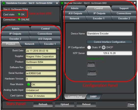
21 B264 Operation and Management The B264 is configured using the free Dashboard application, which is available for Windows, Apple OS X, and Linux. Dashboard can be downloaded from this link: 2 The B264 user interface is depicted below. It is divided into a statistics panel on the left, and a configuration panel on the right. Each panel has multiple tabs, corresponding to the various functions in the card. Note that the Card State alarm indicator is also reflected in the green/red Status LED in the front of the board. The Status LED will be green when Card State is green or yellow, and will be red when Card State is red. For the remainder of this manual, all described features are available for the B264 Stand alone and opengear card versions unless explicitly stated. Both products are referred to as the B264 encoder. The following tabs are available: Product: this tab provides general information on the card, including firmware version, uptime, temperatures, and other parameters. It appears only on the Statistics panel. Network: this tab is used to configure the IP addresses and network information for the Ethernet ports. The statistics side of the panel includes some additional information such as link state. Encoder 1, Encoder 2: these tabs are used to configure the two encoder channels. ASI Outputs: this tab is used to configure/monitor the ASI ports. IP Outputs: this tab is used to configure/monitor the IP Output ports. The configuration panel provides the facilities to create, manage and delete ports; the statistics panel includes transmission status information. Connections: this tab is used to configure/monitor connections. The configuration panel provides facilities to create, edit and delete connections; the statistics panel provides a table where the status of all the connections in the unit can be inspected at a glance. Admin: this tab is used for general administrative functions, such as firmware upgrades, licensing, logs, and configuration management. The Test Packet Generator configuration is also found under this tab. Control: this tab is available only in the B264. It is used to configure/monitor the control ports and the SNMP functions of the device. 2 Please note that DashBoard versions 4.0 and 4.1 have GUI performance problems with the B264 Encoder. We recommend either version 5.0 or higher. 21
22 22

23 Product Tab The Product Tab contains basic information about the B264. The following information is available: Build Date: Date the firmware image was built. Supplier: Niagara Video Corporation. Product: B264, B264 or ITV-B264d. Software revision: This indicates the firmware revision currently running. The format is Major Version Minor Version Build Number. Serial Number: This is the serial number of this particular B264 device. 23
24 Hardware Version: This indicates the board version number. Balanced audio support is available for version 4 and later. All other functionality is the same across hardware versions. Rear Module: This indicates the status of the Rear I/O Module. It can have one of the following states: o OK: The Rear Module is the correct module for the B264. In the B264 this indicator will be always green. o Not Installed: The B264 is not connected to a rear module. The card is operating normally, but it will not be useful as there are no input and output connections to it. o Wrong Module: The B264 is connected to a rear module that was not designed for it (most likely from another opengear vendor). Depending on the signals present on that module, there may be a small chance of damage to the B264; Niagara Video recommends that this situation be rectified immediately. This alarm will cause the front status LED to turn red. A card with hardware version 3 or lower will show this alarm for the balanced audio rear I/O panel. Analog Audio Input: This indicates the type of analog audio input (balanced or unbalanced). This field will have an indication of unknown for unrecognized/unsupported rear I/O panels. Card Uptime: Indicates how long the card has been running since it was last rebooted. Ambient Temperature: Temperature, in degrees centigrade, of the air intake of the card (measured at the front edge of the card). Internal Temperature: Temperature, in degrees centigrade, at the back of the card. MDP Core Temperature: Temperature, in degrees centigrade, of the core MediaStorm processing element. The opengear frame is designed to operate in environments with up to 40 o C ambient. There is typically a 5 o C temperature raise from the external ambient to the Ambient Temperature measured by the B264. If that measurement is at 45 o C or higher, action must be taken to cool down the ambient temperature. The B264 modular versions are designed to operate in environments with an ambient temperature between 0 and 50 o C. Network Tab The Network Tab allows for configuration/monitoring of the two streaming Ethernet ports, and optional configuration of DNS servers. Network Configuration Tab The Network Configuration Tab is further divided into the following tabs: The Interfaces tab is used to set the individual parameters for each of the streaming Ethernet ports. The DNS tab is used to optionally configure DNS servers. 24

25 Configuration Tabs Network Configuration Interfaces Tab This tab allows the configuration of the individual streaming ports. The following parameters can be configured: Alarm on Link Loss: If set to Yes, the card will raise an alarm if this Ethernet interface loses link. The Card State indicator in Dashboard and the front Status LED will both be red. If set to No, the card will still report loss of link in the Statistics page but no alarm will be raised. Niagara Video recommends turning on the alarm for ports that are in use; only turn it off if you do not plan to connect that port to a network. IP Address: Enter the desired IP address for this Ethernet port. In the B264, this IP address cannot be the same as the Control Port IP Address (see the Control Port Configuration Tab). Subnet Mask: Enter the desired subnet mask for this Ethernet port. Default Gateway: Enter the desired default gateway for this Ethernet port, or if no gateway is available. Interface Settings: If you make any changes to the IP Address, Subnet Mask and/or Default Encoder fields, the Apply and Cancel buttons become active. The changes only take effect when you press the Apply button. Pressing the Cancel button reverts the fields back to their original values. Note that the B264 will check the consistency of the data entered and will reject invalid combinations (i.e., combinations where the gateway is outside the interface subnet). Once the Apply button is pressed, a status message appears just below the Cancel button, as follows: 25


26 Interface speed: Configures the speed of the interface. The B264 streaming Ethernet interfaces only support two manual modes: 100 Mb/s Full-Duplex and 1 Gb/s Full- Duplex 3. o Auto-Negotiate: The Ethernet port will auto-negotiate the speed. o 100 Mb/s Full-Duplex: Force the port to 100Mb/s Full-Duplex mode. Note that the port will still perform auto-negotiation, but it will only advertise this mode. o 1Gb/s Full-Duplex: restrict the operation to 1Gb/s Full-Duplex mode. Note that the port will still perform auto-negotiation, but it will only advertise this mode. Notes: o If the B264 streaming Ethernet interfaces are connected to a 10 Mb/s switch, hub, or network feed, link will not be established and the port will not recognize the connection. o If you select 100 Mb/s Full-Duplex or 1 Gb/s Full-Duplex and the corresponding streaming Ethernet interface is connected to a switch, hub or network feed that does not support the selected speed, link will not be established and the port will not recognize the connection. o If the interface speed is set to Auto-Negotiate, the streaming Ethernet port will allow link to be established in 100 Mb/s Half-Duplex mode. However, this will be flagged as a warning in the Network Statistics Interface Tab and in the Admin Event Log Tab. Network Configuration DNS Tab The DNS tab allows manual configuration of up to two DNS servers. They do not need to be in the same subnetwork as the streaming ports, as long as at least one default gateway is configured. DNS is only used in conjunction with the RTMP output functionality. If you are not using RTMP, there is no need to configure DNS servers. DNS server configuration takes effect immediately, as soon as the information is entered. 3 Niagara Video has disabled support for 10 Mb/s modes, as these are unsuitable for MPEG transport over IP applications. Moreover, any modern switch supports at least 100 Mb/s Full-Duplex. 26

27 In the B264 Modular Encoder, it is also possible to configure DNS in the Control Tab. DNS Servers configured in the Control Tab have priority over servers configured here. Network Statistics Tab The Network Statistics Tab is subdivided into the same tabs as the Network Configuration Tab, namely Interfaces and DNS. Network Statistics Interface Tab The Interface Tab reports the current IP configuration of each Ethernet port, as well as their link state and running status. The following parameters are reported in the Network Statistics tab: Alarm on Link Loss: Reports the current setting of this parameter. IP Address: Reports the current IP Address for the port. Subnet Mask: Reports the current Subnet Mask for the port. Default Gateway: Reports the current Default Gateway for the port. Interface Speed: Reports the current setting for this parameter. Port 1/2 Link: This indicator has the following states: o Link OK: The port has established link with the network connection. o Half-Duplex Link: The port is set to Auto-Negotiate, and it has achieved 100 Mb/s Half-Duplex link with the network connection. Niagara Video does not consider Half-Duplex links suitable for video communication. The port will operate, but we recommend that this be addressed. If Alarm on Link Loss is set to Yes, the Dashboard Card State will be yellow if there are no higher-priority alarms present. o No Link: The port does not currently have link. If Alarm on Link Loss is set to Yes, the Dashboard Card State will be red and the Status LED in the front of the 27
.")
28 board will also be red. If Alarm on Link Loss is set to No, this indicator will still be red, but the alarm will not propagate. Port 1/2 Status: This indicator is the port overrun status. It has the following states: o OK: The port is operating normally. o TX Overflow: In the current configuration, the IP outputs are attempting to transmit more than the port capacity (i.e., the overall output data for this port exceeds the interface speed of 100 Mb/s or 1 Gb/s). The Dashboard Card State will be red and the Status LED in the front of the board will also be red. In this case, reduce the output bit rate (either by reducing the encoder bit rates or by removing output ports). If this indicator is red, data is being dropped. Link Speed (Mb/s): This parameter reports the actual speed negotiated with the switch for the port. If the port has no link, the value reported here is zero. MAC Address: This reports the MAC address of the Ethernet port. Network Statistics DNS Tab The Network Statistics DNS Tab reports the current DNS configuration. 28
.")
29 Encoder 1, Encoder 2 Tabs The Encoder 1/Encoder 2 Tabs are used to configure/monitor the individual encoder channels. The parameters in these two tabs are exactly the same. The B264 can be configured with one or two encoder channels (at the time the unit is ordered, factory installed). It is possible to upgrade a single channel B264 unit to dual channel by returning it to Niagara Video. If an encoder channel is not installed, both its configuration and statistics windows will be empty, as shown below. Encoder Configuration Tab The Encoder Configuration Tab is further divided into the following 3 tabs: Basic Tab: contains the more important configuration parameters, which all users are likely to change. Advanced Tab: contains the advanced configuration parameters, which do not necessarily need to be changed. Connections Tab: allows the creation of connections between this encoder and the ASI and IP output ports. Configuration Tabs 29
30 In general, the encoder user interface will change as a function of the parameter selections made, to remove illegal parameter combinations. Selections made in any of the encoder configuration screens do not take effect until the Apply button is pressed. If you wish to discard the changes made to the user interface, press the Cancel button. The Apply/Cancel buttons are present in all the tabs and will be grayed out until changes are made. At any given point in time, the currently running encoder configuration can be inspected in the Encoder Statistics Tab, described later in this document. Video Input Auto-Detection The B264 can be set to auto-detect the video input signal, and self-configure for the incoming resolution and frame rate. This feature allows the encoder to operate in situations where the video signal can change over time (for example, at the output of a video switch). The B264 is even capable of automatically recognizing whether a signal is SDI or composite, and the video standard for composite signals. The following points should be considered when using video input auto-detection: The available output scaling options are limited, since some options are specific to some input resolutions. If the encoder is not licensed for a given configuration, it will stop encoding if the input video signal switches to a value that requires this configuration. For example, an SD encoder configured to output the same resolution as the input will stop if the input signal switches to HD. If the encoder is configured with auto-detection and SDI embedded audio, it will fall back to analog audio if it detects a composite video signal. If your input can switch between SDI and composite, either use analog audio for all signals, or make sure that the corresponding analog audio signal is present at the encoder unbalanced audio inputs when the video is a composite signal. Multiple Audio Support The B264 can be licensed to offer up to two additional MPEG-1 Layer II audio channels, regardless of the number of installed encoders. These additional audio channels can be associated with the first or second encoder. Moreover, a dual-channel encoder can be configured as a single-channel encoder with combined audio. The following combinations are supported: Single Channel Encoders: support for 1, 2 or 3 audio stereo pairs, as follows: o First stereo pair: MPEG-1 Layer II, AAC-LC or Dolby Passthrough support Valid inputs: analog unbalanced audio, SDI embedded (SDI signals only) o Second stereo pair: MPEG-1 Layer II support only Valid inputs: second analog unbalanced audio, SDI embedded (SDI signals only) o Third stereo pair (only available for SDI inputs): MPEG-1 Layer II support only Valid input: SDI embedded 30
31 Dual Channel encoders: support for 1 or 2 audio stereo pairs per encoder channel, as follows: o First stereo pair: MPEG-1 Layer II, AAC-LC or Dolby Passthrough support Valid inputs: analog unbalanced audio, SDI embedded (SDI signals only) o Second stereo pair (only available for SDI inputs): MPEG-1 Layer II support only Valid input: SDI embedded Dual Channel encoders can be configured to have one encoder channel with 3 audio stereo pairs, and another encoder channel with 1 audio stereo pair, as follows: o Encoder with 1 stereo pair: MPEG-1 Layer II, AAC-LC or Dolby Passthrough support Valid inputs: analog unbalanced audio, SDI embedded (SDI signals only) o Encoder with 3 stereo pairs: First stereo pair: MPEG-1 Layer II, AAC-LC or Dolby Passthrough support Valid inputs: analog unbalanced audio, SDI embedded (SDI signals only) Second stereo pair (only available for SDI inputs): MPEG-1 Layer II support only Valid input: SDI embedded Third stereo pair (only available for SDI inputs): MPEG-1 Layer II support only Valid input: SDI embedded Dual Channel encoders with combined audio: support for up to 4 audio stereo pairs per board, as follows: o First stereo pair: MPEG-1 Layer II, AAC-LC or Dolby Passthrough support Valid inputs: analog unbalanced audio, SDI embedded (SDI signals only) o Second stereo pair: MPEG-1 Layer II, AAC-LC or Dolby Passthrough support Valid inputs: second analog unbalanced audio, SDI embedded (SDI signals only) o Third stereo pair (only available for SDI inputs): MPEG-1 Layer II support only Valid input: SDI embedded o Fourth stereo pair (only available for SDI inputs): MPEG-1 Layer II support only Valid input: SDI embedded Encoder Basic Configuration Tab The Encoder Basic Configuration Tab, shown below, is divided into three general areas: General Configuration: generic configuration parameters. 31

32 Video Configuration: parameters related to video encoding. Audio Configuration: parameters related to audio encoding. General Configuration Video Configuration Audio Configuration Apply/Cancel Configuration Changes Note that the basic configuration tab may look different from what is depicted above, as the parameters may change (or appear/disappear in the GUI) based on the device s configuration and the parameter choices made. 32


33 Basic Tab General Configuration Name: All B264 encoders and outputs can be assigned a user-defined name. This name is used to identify the encoder later when making connections. Use any descriptive name suitable for your application, or accept the default. Encoder State: This control allows you to start/stop an encoder. This control needs to be set to Running for normal operation. Input Connection: This control selects which of the two rear I/O panel inputs is to be connected to this encoder. The B264 can run both encoders from the same input. The default is to run Encoder 1 from Video/Audio 1 and Encoder 2 from Video/Audio 2, but all combinations are allowed. Note that the parameters presented in the Video Configuration section may change if this selection changes (for example, if you switch the encoder from a Composite input to an SDI input). Basic Tab Video Configuration The B264 is capable of automatically identifying the video signal present in the selected input connection. The detected signal is reported in the Encoder Statistics Tab. Additionally, the encoder can also be set to auto-configure its input based on the detected signal: Video Input Settings: This parameter selects whether or not the encoder will autoconfigure based on the detected video input signal. o Manual Selection: The input signal must be correctly selected using the Input Resolution, Input Source, and Field/Frame Rate controls for the encoder to run. If the input signal does not match the settings, the encoder will not run. o Auto Detected: The encoder will auto-detect the input signal, and automatically configure for it if it is a supported signal. The Input Resolution, Input Source, and Field/Frame Rate controls are not displayed. 33
34 The following table lists the supported input video signals: Composite Signals NTSC NTSC 4.43 PAL B/D/G/H/I/N PAL-M PAL-Nc SECAM SDI Signals i i p p p p p i i i p p p60 If Video Input Settings is set to Manual Selection, the Input Resolution, Input Source and Field/Frame Rate parameters are displayed and must be set to match the incoming video signal. Input Resolution: Select the resolution of the input video signal. The following four choices are available: o SD: i (this will be presented as i if Field/Frame Rate is set to PAL). o HD: p o HD: i o HD: p Input Source: Select the input source type. This control is available only if the Input Resolution is set to SD. In this case, the options will be Composite or SD-SDI. If Input Resolution is set to any of the HD values, this control will not be selectable, and will show the appropriate type of input (HD-SDI for p and i, and 3G-SDI for p). Field/Frame Rate: Select to match your source. For all input resolutions, the supported options always include (for NTSC-based systems) and 50 (for PAL-based systems) 4. Some resolutions have support for additional frame rates, as follows: o If you select the i or p resolutions, this field will also include an option for a field rate of 60, used by same cameras: 4 Niagara Video may offer support for other standard frame rates, such as 30, 60, 24, etc. Please contact us if you require one of these rates. 34

 o ¾ scaling from the input o Low resolutions: 480 270, 320 240, and 320")
35 o If you select the p resolution, this field will also include an option for a frame rate of (Film): Output Resolution: Select the desired output resolution. The values in this drop-down list are a function of the Video Input Settings, the Input Resolution and the Frame/Field Rate. Also, please note that some resolutions require additional licensing for the encoder. If Video Input Settings is set to Manual Selection, the following resolutions are offered: o Same as the input (no scaling) o ¾ scaling from the input o Low resolutions: , , and , progressive, at half and quarter frame rates (not available for 1080p inputs) o HD inputs can be scaled (and re-interlaced if necessary) to SD resolution, anamorphic (not available for 1080p inputs) o 720p inputs can be reduced to half frame rate (typically for Internet applications), as follows: p50 is converted to p p59.94 is converted to p p60 is converted to p30 o 1080i, 720p and SD inputs can be converted to SD resolution, with progressive frame rates (ideal for computer displays), as follows: 1080i59.94, 720p59.94, and 480i59.94 are converted to p i60 and 720p60 are converted to p i50 and 720p50 are converted to p25 The conversions from HD resolutions are done using anamorphic scaling. o 1080i, 720p and SD 5 inputs can be scaled to , with progressive frame rates, as follows: 1080i59.94 and 480i59.94 are converted to p p59.94 is converted to p i50 and 576i50 are converted to p25 720p50 is converted to p50 5 By default, SD signals have a 4:3 aspect ratio, unless they are derived from an HD source with anamorphic scaling. The resolution is intended for 16:9 content. Scaling SD to should only be done if the SD signal is anamorphic to start with, otherwise the resulting encoded signal will have an incorrect aspect ratio. 35
 o HD 1080i inputs can be scaled to ¼ resolution (960 540), with the same incoming frame rate o SD inputs can be horizontally cropped to 704 pixels or")
36 o HD 1080i inputs can be scaled to p at the same incoming frame rate (e.g., 1080i59.94 will be scaled to 720p29.94; 1080i50 will be scaled to 720p25) o HD 1080i inputs can be scaled to ¼ resolution ( ), with the same incoming frame rate o SD inputs can be horizontally cropped to 704 pixels or horizontally scaled to 640 pixels o SD inputs can be horizontally scaled to 640 or 528 pixels, and converted to progressive frame rates (29.97p for NTSC inputs, 25p for PAL inputs) If Video Input Settings is set to Auto Detected, the following options are offered in this parameter: o Same as Input: the encoder will produce a signal that has the same resolution and frame rate as the input (no scaling). o Scale 3/4 Horizontal: the encoder will scale down the image horizontally by 3/4. The frame rate will not be changed. o Scale to p: the encoder will scale the input video to The frame rate will be the same as the input, but interlaced inputs will be de-interlaced (for example, i60 will yield p30). This resolution is not available for p inputs at any frame rates; the encoder will fall back to 3/4 horizontal scaling in this case. o Scale to p, Scale to p, Scale to p: the encoder will scale the input video to the selected resolutions. Interlaced inputs will be deinterlaced as described above. Progressive inputs will be encoded at half frame rate. This resolution is not available for p inputs at any frame rates; the encoder will fall back to 3/4 horizontal scaling in this case. Video Rate Mode: This controls whether the video elementary stream is CBR or VBR. The video bit rate setting varies according to this selection, as shown below. Bit Rate Selection: This field is shown only if the encoder is set to CBR mode, and allows the user to specify either the video bit rate, or the transport bit rate. The transport bit rate includes audio, video, tables, NULL packets, and various overheads. In some situations, such as for example, RF links of fixed capacity, it is more convenient to specify the transport rate (i.e., the final bit rate in the wire ), and let the encoder compute the corresponding video bit rate to yield the desired transport rate. In other situations, such as IPTV deployments, it is more convenient to simply specify the video bit rate and let the encoder compute the final transport rate. Note that this control is not available in the OTT protocol modes. The controls displayed vary according to this selection: 36
37 Video Bit Rate: This field is shown only if the encoder is set to CBR mode and the Bit Rate Selection control is set to Video Bit Rate. It determines the video elementary stream bit rate, expressed in bits/second. Note that the bit rate resolution is 1000 bits/second. Transport Bit Rate: This field is shown only if the encoder is set to CBR mode and the Bit Rate Selection control is set to Transport Bit Rate. It determines the overall transport stream bit rate, with a resolution of 1000 bits/sec; the encoder will calculate the appropriate video bit rate the yield the desired transport rate. Please note that all transport rates are achievable; in particular, the encoder may not be able to achieve very low transport rates if the audio bit rates are high. In these cases, the actual transport rate output by the encoder will be higher than the configured value. The actual transport rate is displayed in the Encoder Statistics Tab, after the Apply button has been pressed. At that point, the actual encoder video bit rate can be found in the Encoder Statistics Tab, under the Basic bottom tab. Peak Video Bit Rate, Average Video Bit Rate: These two fields are shown only if the encoder is set to VBR mode, and determine the desired average and acceptable peak bit rates for the video elementary stream. The peak video bit rate must be between 1.5 and 2 times the average bit rate; the user interface will enforce these limits automatically (i.e., it will update either the average or peak to be consistent with the value being entered). For both of these parameters, the resolution is 1000 bits/sec. Basic Tab Audio Configuration Audio Source: This parameter selects the audio source. The options are Analog Audio, directing the encoder will to use the analog right/left audio channels connected to the selected rear I/O panel, and SDI Embedded Audio, directing the encoder to extract embedded audio from the SDI input. If the video Input Source (see Basic Tab Video Configuration) is set to Composite, this parameter is grayed out and forced to Analog Audio. It will be selectable only if the video input source is one of the SDI variations, or if Video Input Settings is set to Auto Detected. Please note that if the encoder is set to auto-detect the video input, and it detects a composite signal, the audio selection will fall back to analog audio regardless of the Audio Source settings. When SDI Embedded Audio is selected, additional configuration options become available, as shown below. 37

38 Group, Channels: SDI embedded audio is typically divided into four groups (denoted by Group 1 to Group 4); each group has four mono channels (2 stereo pairs), denoted by Channels 1-2 and 3-4. These controls allow the selection of the desired group and channel pair. In the large majority of the cases, the first stereo pair is in Group 1, Channels 1-2, the second stereo pair is in Group 1, Channels 3-4, and so on. The Group selection has one additional choice, labeled Custom DID. This allows the encoder to use a non-standard embedded audio DID (this quite uncommon). If Custom DID is selected, a new configuration option becomes available, where the DID value can be entered: Group DID: Enter the desired Group DID, in hexadecimal. Note that the entry will be immediately validated and rejected if invalid. As a reference, the table below contains the standard DIDs built into the system for Groups 1 to 4. Group SD-SDI DID HD-SDI DID Group 1 0x2FF 0x2E7 Group 2 0x1FD 0x1E6 Group 3 0x1FB 0x1E5 Group 4 0x2F9 0x2E4 Language Code: This parameter represents the 3-letter ISO language code for the audio, to be placed in the audio language descriptor in the PMT. For a complete list of the language codes, see this URL: If the Output Protocol in the Encoder Connections Tab is set to RTMP, this field will not be displayed as RTMP does not use the transport stream container. Audio Encoding: This parameter selects the audio encoding algorithm. The available choices depend on the Audio Source selection. For Analog Audio, the choices are MPEG-1 Layer II and AAC-LC. For SDI Embedded Audio, the Dolby Passthrough 38


39 option is offered in addition to the previous choices. Note that AAC-LC requires additional licensing. The two variants for this control are depicted below. If the Output Protocol in the Encoder Connections Tab is set to RTMP, this field is forced to AAC-LC and becomes not editable. The reason is that the RTMP protocol has no support for MPEG-1 Layer II audio at 48 khz sampling. It also has no support for Dolby. Mode: The available choices for this parameter depend on the Audio Encoding selection, as follows: o MPEG-1 Layer II: the available modes are Stereo or Single Channel. If you select Single Channel (Mono), only the audio connected to the Left input will be encoded. o AAC-LC: the available modes are Stereo, Mono, or Dual Mono. If you select Mono, only the audio connected to the Left input will be encoded. o Dolby Passthrough: This parameter is not displayed. Audio Bit Rate: The format of this parameter is a function of the Audio Encoding setting. For MPEG-1 Layer II, this parameter is a drop-down list of valid discrete bit rates; the values in the list are also a function of the Mode Setting. For AAC-LC, the range is 112 to 512 kb/s for Stereo and Dual Mono, and 56 to 256 kb/s for Mono. This parameter is not displayed for Dolby Passthrough as the B264 will automatically detect the incoming audio bit rate. Peak Audio Bit Rate: This parameter is only displayed for AAC-LC. It must be set at least 1 kb/s higher than the Audio Bit Rate. The maximum value is 288 kb/s for Mono, and 576 kb/s for Stereo and Dual Mono. Sample Rate: This field is for information purposes only. The B264 only supports 48 khz audio sample rate. 39


40 Basic Tab Additional Audio Support If the encoder is in a configuration where additional audio channels can be offered, a checkbox to enable them will be presented in the GUI, as indicated below: If the box is checked, additional fields will become available for configuring the additional audio channel. These fields are the same as with the first audio channel. Note that, depending on the configuration, the Audio Source selection may be grayed out. After the first additional audio is enabled, the encoder may offer a second additional audio channel, as depicted below: The second additional audio option will be offered in the following conditions: In a single-channel encoder, if the input signal type is SDI. In a dual-channel encoder, if the first additional audio is not being used by the other encoder channel. In a dual-channel encoder, if secondary audio is enabled (see the next section). Additional audio channels are only available if the Output Protocol in the Encoder Connections Tab is set to ASI/IP Streaming. 40

41 Basic Tab Secondary Audio Support A dual-channel B264 can be configured to offer secondary audio support (i.e., a second audio PID in the same program). If this function is available, it will be available in the audio section of Encoder 1, as indicated below: Secondary audio support is only available if the Output Protocol in the Encoder Connections Tab is set to ASI/IP Streaming. When Secondary Audio is set to Enabled, the Encoder 1 Audio Configuration section will change as indicated below: 41

42 The individual controls work in the same manner as discussed before. Each audio channel can be independently configured. As before, the SDI Embedded Audio option will only be available if the Encoder 1 input selection is one of the SDI variants. The only input restriction is that, when using Analog Audio, the signal connected to Video/Audio 1 will be the first audio channel, and the signal connected to Video/Audio 2 will be the second audio channel. Secondary audio support can be combined with the two additional audio channels to create one program with up to 4 audio services (i.e., up to 4 audio PIDs). Support for secondary audio requires that both encoder channels in the board be tied together. When the Secondary Audio control depicted above is set to Enabled, Encoder 2 will be slaved to Encoder 1. Its Basic Configuration Tab in this mode is depicted below: 42
 controls are slaved to the corresponding controls in Encoder 1. They will reflect the state of their Encoder 1 counterparts.")
43 Controls Slaved to Encoder 1 Controls Shared with Encoder 1 Encoder 2 Audio Insertion Controls The operation is as follows: The Encoder State, Input Selection, Video Input Settings, Output Resolution and Coding Delay (in the Advanced Tab) controls are slaved to the corresponding controls in Encoder 1. They will reflect the state of their Encoder 1 counterparts. If Video Input Settings in Encoder 1 is set to Manual Selection, the Input Resolution, Input Source and Field/Frame Rate controls are shared with Encoder 1, and apply to whatever input port is selected. Changes here will be mirrored in the corresponding parameters for Encoder 1. If Video Input Settings in Encoder 1 is set to Auto Detected, these controls are not displayed. Encoder 2 can optionally share one or both audio channels from Encoder 1. This is accomplished by checking Include Audio Ch1/2 boxes in the Audio Insertion Controls displayed above. Encoder Advanced Configuration Tab The appearance of the Encoder Advanced Configuration Tab is a function of the choices made in the Multiple Audio Support section of the Encoder Basic Configuration Tab. The Advanced Configuration Tab is divided into four major areas: Video Parameters: these are advanced controls related to the encoding of the video. VBI/Ancillary Data Insertion: controls related to Closed-Captioning and Active Format Description (AFD) insertion. Audio Parameters: these are advanced controls related to the audio subsystem. 43

44 Mux Parameters: these are advanced controls related to audio/video multiplexing and (P)SI tables. Advanced Tab Video Parameters The Video Parameters section is shown below: GOP Mode: Select between Open GOP and Closed GOP. The normal setting is Open GOP. Closed GOP is used for some storage applications, and is also required by some CDNs (such as YouTube); there is a very small negative impact in video quality if Closed GOP is selected. For some output protocols (HLS and RTMP), this control becomes read-only and is forced to Closed GOP. Level: Selects the H.264 level signaled in the bitstream. The default setting is Auto- Select, whereby the encoder will signal the minimum required level based on the current settings. If, for some reason, a different (higher) level is desired, it can be selected here. Note that the encoder will not honor a level selection that is lower than the legal minimum for the current settings. It is typically not necessary to change the level from Auto-Select. Profile: This control has four options: o Auto-Select: With this setting, the encoder will use High Profile for HD and Main Profile for SD. o High Profile: With this setting, the encoder will always use High Profile for all resolutions. o Main Profile: With this setting, the encoder will always use Main Profile for all resolutions. o Baseline Profile: With this setting, the encoder will always use Baseline Profile. The GOP Structure control will not be selectable in Baseline Profile and will be set to IP. Note that, as the profile is lowered, there will be video quality degradation. In other words, for a given resolution and bit rate, the video quality for High Profile will be better than Main Profile, and Main Profile will be better than Baseline Profile. Whether the quality difference is noticeable will depend on the resolution, bit rate, and specific video content. 44
.")
45 Aspect Ratio: The H.264 bitstream includes aspect ratio information in the VUI Parameters part of the Sequence Parameter Set. Normally, the encoder will automatically set the correct aspect ratio code. However, in some situations, it may be necessary to override this (for example, when scaling HD to SD). Use this control to override the default aspect ratio set by the encoder. In particular, if the video input is 1920x1080i, and the content is being scaled to SD, use either 16:11 (PAL Widescreen) or 40:33 (NTSC Widescreen) to get the correct aspect ratio. GOP Structure: Select between IBBP, IBP and IP. Selecting IBBP gives the best video quality, but some low-end decoders require IP. If Profile is set to Baseline Profile, this control will not be selectable and will be forced to IP. Coding Delay: This parameter controls the size of the H.264 Coded Picture Buffer (CPB), expressed in milliseconds. This is one component of the end-to-end encoder/decoder delay. The B264 latency is 150 milliseconds plus the value of this control. For example, if the Coding Delay is set at its default of 500 milliseconds, the B264 latency will be 650 milliseconds. Note that the overall encoder/decoder latency is also a function of the latencies in the decoder. Please note that reducing the coding delay will reduce latency at the expense of video quality! Use VBR if at all possible when reducing the latency, and set the peak rate as high as you can afford. For example, if the encoder output is i, a bit rate on the order of 10 to 12 Mb/s (either CBR average or VBR peak) is required to produce a stream without artifacts with a Coding Delay of 100 milliseconds. Note that if the Output Resolution setting in the Basic Tab Video Configuration is set to one of the low resolutions ( , , or ), the Profile and GOP Structure controls will not be selectable; this section will appear as follows: Also note that if the Input Resolution setting in the Basic Tab Video Configuration is set to p, the Profile and GOP Structure controls will not be selectable; this section will appear as follows: 45
 SCTE 104 Ad Insertion Triggers Closed Captioning The Closed Captioning controls are only displayed in the following situations: In the Basic Tab Video Configuration, Video Input")
46 Advanced Tab VBI/Ancillary Data Insertion The B264 can extract the following data types from the video input and insert them in the compressed video output: Closed Captioning Active Format Description (AFD) SCTE 104 Ad Insertion Triggers Closed Captioning The Closed Captioning controls are only displayed in the following situations: In the Basic Tab Video Configuration, Video Input Settings is set to Manual Selection, and Frame/Field Rate is set to (NTSC). In the Basic Tab Video Configuration, Video Input Settings is set to Auto Detected. The appearance of this control is also a function of the Video Input Settings, Input Resolution and Input Source parameters, as depicted below. The Closed Captioning controls are as follows: Enable CC: check this box to enable Closed-Captioning insertion. Closed Captions are inserted in the video elementary stream, as per ATSC A/72. Both CEA-608 and CEA-708 captions are supported. CC Source: this controls where the encoder extracts closed captions from. As depicted below, this field may or may not be editable, depending on the video input settings, input resolution and input source. The options are: o CEA-608 Line 21: this option can only be used for SD inputs. The encoder will extract all the CEA-608 information from both fields of Line 21, if present. o SMPTE-334 VANC: this option can only be used for SDI inputs. The encoder will expect closed-captioning information in the VANC. Both CEA-608 and CEA-708 modes are supported (and automatically detected). Note that if Video Input Settings is set to Auto Detected, the encoder will comply with the CC Source if possible, but may fall back to another setting depending on the input signal. For example, if CC Source is set to CEA-608 Line 21 and the encoder detects an HD signal, it will fall back to SMPTE-334 VANC. Conversely, if it is set to SMPTE-334 VANC and it detects a composite signal, it will fall back to CEA-608 Line 21 if that composite signal is NTSC, or turn off CC if that composite signal is PAL. 46
 information from the incoming video signal and insert it in the compressed bitstream.")

. The B264 also has the option of inserting a user-defined AFD code (instead of receiving it from the video input).")
47 Closed-Captioning Disabled Input Source: SD-SDI Input Resolution: SD or Video Input Settings: Auto Detected Input Source: Composite Input Resolution: SD Input Source: HD-SDI or 3G-SDI Input Resolution: HD Active Format Description The B264 can extract Active Format Description (AFD) information from the incoming video signal and insert it in the compressed bitstream. AFD information can be extracted from the following sources: For SDI signals, AFD information can be present in the VANC as per SMPTE This is the primary way of conveying AFD information on a professional video feed. For SD signals (either from Composite or SD-SDI sources), AFD information can be synthesized from Wide Screen Signaling (WSS) data present in the VBI (line 20 for NTSC signals, line 23 for PAL signals). The B264 also has the option of inserting a user-defined AFD code (instead of receiving it from the video input). The AFD controls are as follows: Enable AFD: Check this box to enable AFD extraction and insertion. This control is always available. AFD is inserted in the video elementary stream as per ATSC A/72 and ETSI TS AFD Source: This controls where the AFD information is coming from. The options are: o Line 20 WSS/Line 23 WSS: This option causes the encoder to synthesize AFD information from WSS. It is available only if the input resolution is SD or if the video input settings are auto-detected. It will be displayed as Line 20 for NTSC and Line 23 for PAL. For PAL inputs, the conversion follows ETSI TS Appendix B.4. 47


48 o SMPTE VANC: This option causes the encoder to extract AFD from the VANC. It is only available for SDI inputs or if the video input settings are autodetected. o Manual AFD Selection: This option allows the user to specify a fixed AFD code to be inserted. Any AFD information received from the input is ignored. This can be used to override the original AFD information, or when the video is being scaled (e.g., when the input is HD and is being converted to SD). AFD Code: This control is displayed only when AFD Source is set to Manual AFD Selection. It corresponds to the codes listed in SMPTE , Table 1. Composite SD-SDI Auto-Detected HD Note that if Video Input Settings is set to Auto Detected, the encoder will comply with the AFD Source if possible, but may fall back to another setting depending on the input signal. For example, if AFD Source is set to Line 20/23 WSS and the encoder detects an HD signal, it will fall back to SMPTE VANC. Conversely, if it is set to SMPTE VANC and it detects a composite signal, it will fall back to Line 20/23 WSS (and automatically use the correct line number based on the input signal). Manual AFD Selection is always honored. 48

 according to the selections made in the various audio configuration")
49 SCTE 104 Ad Insertion Triggers If the input signal is SDI, the B264 is capable of extracting SCTE 104 triggers from the VANC (inserted as per SMPTE 2010) and converting them to SCTE 35 triggers in the output transport stream: Enable SCTE 104/35: Check this box to enable SCTE 104 extraction. Note that this control is only displayed if the input signal is SDI or if the encoder is in auto-detect video mode. Advanced Tab Audio Parameters The Audio Parameters are divided into three subgroups, some of which vary (and may not be present) according to the selections made in the various audio configuration sections in the Encoder Basic Configuration Tab and the installed rear I/O panel. A sample of the Audio Parameters section is depicted below. Analog Audio Parameters A/V Sync Adjustment PMT Information Audio Encoder Specific Configuration 49
50 Analog Audio Parameters These parameters are only displayed if Audio Source in Basic Tab Audio Configuration is set to Analog Audio. The parameters are: Balanced Audio Level: This control is only displayed if the encoder is equipped with a balanced audio rear I/O panel. It selects the nominal signal level, as follows: o SMPTE: Nominal level according to SMPTE RP155, typically used in North America. o EBU: Nominal level according to EBU R68, typically used in Europe. The EBU level is 6 db higher than the SMPTE level. Audio Gain L (db), Audio Gain R (db): These controls allow an independent gain adjustment for the left/right audio channels, from db to db, in steps of 0.5 db. Audio Mute L, Audio Mute R: These controls allow muting of the left/right audio channels. A/V Sync Adjustment This parameter can be used to provide a small amount of A/V sync adjustment, for cases where the A/V sync in the input signal to the encoder is not correct. If, in the input signal, audio is behind the video, you can use this parameter to compensate for up to 100 milliseconds. Note that it is only available for MPEG-1 Layer II and AAC-LC encoding; it will not be displayed for Dolby Passthrough. Audio Delay (ms): Use this to compensate for up to 100 milliseconds of audio delay in the input signal. This setting will advance the audio in relation to the video by the amount configured. PMT Information The PMT Information section has the following parameters: Audio Type: determines the audio type in the PMT audio descriptor. This setting has no actual impact on how the audio is encoded; it only affects its description in the PMT. The choices are: o Undefined: no further information. This is the most common setting. o Clean Effects: indicates that the audio has no language. o Hearing Impaired: indicates that the audio is prepared for the hearing impaired. o Visual Impaired Commentary: indicates that the audio is prepared for the visually impaired viewer. If the Audio Encoding setting in the Basic Tab Audio Configuration is set to Dolby Passthrough, another parameter becomes available in the PMT Information section: 50
.")
51 Dolby PMT Type: this parameter controls how Dolby AC-3 audio is signaled in the PMT. The two choices are: o DVB: Dolby Audio is signaled as per ETSI TS Appendix C (stream_type 0x06 with the AC-3 Descriptor from EN annex D). o ATSC: Dolby Audio is signaled as per ATSC A/53 Part 3 (stream_type 0x81). However, the B264 is currently unable to generate the ATSC AC-3 Descriptor; please contact Niagara Video if this is an issue in your network. If the Output Protocol in the Encoder Connections Tab is set to RTMP, the PMT Information fields will not be displayed as RTMP does not use the Transport Stream container. Audio Encoder Specific Configuration The appearance of this control depends on the Audio Encoding setting in the Basic Tab Audio Configuration. AAC-LC Configuration MPEG-1 Layer II Configuration The parameters are: CRC: Enables/Disables CRC insertion in the audio elementary stream. This is normally left disabled (CRC off). Original/Copy: Controls the state of the Original/Copy flag in the audio elementary stream. This setting does not affect the actual audio encoding. Copyright: Controls the state of the Copyright flag in the audio elementary stream. This setting does not affect the actual audio encoding. Emphasis: Controls the state of the Emphasis flags in the audio elementary stream. This setting does not affect the actual audio encoding. The available values are None, 50/15 us, and ITU-T J.17. Advanced Tab Additional Audio Channels When Secondary Audio is set to Enabled, or Additional Audio Channels are enabled, the following changes take place: Additional sets of controls are displayed in the Encoder Advanced Tab, corresponding to each of the enabled audio channels. Each set operates independently as described in the previous section. If Secondary Audio is set to Enabled, no Advanced Audio controls are displayed in the Advanced Tab for Encoder 2. 51


52 The example below illustrates the Advanced Audio controls when one additional audio is enabled. In this example, Audio Channel 1 is set to MPEG-1 Layer II, from the analog input, and Audio Channel 2 is set to Dolby Passthrough. Advanced Tab Mux Parameters These parameters control the details of the audio/video multiplexing, and the (P)SI tables. If the Output Protocol in the Encoder Connections Tab is set to RTMP, these parameters will not be shown as RTMP does not use the Transport Stream container. The following Mux Parameters are always available if the Output Protocol is not set to RTMP: 52
 or in decimal. Valid values are from 0x20 (32) to 0x1FFE (8190). PMT PID, Video PID and Audio PID must be distinct values.")
53 PMT PID, PCR PID, Video PID, Audio PID, SCTE 35 PID: These parameters control the Packet Identifier (PID) values for the PMT, PCR, Video and Audio. The values can be entered in hexadecimal (prefixed by 0x) or in decimal. Valid values are from 0x20 (32) to 0x1FFE (8190). PMT PID, Video PID and Audio PID must be distinct values. PCR PID can either be the same as the video PID or distinct from the other values as well. The user interface will not accept an invalid entry at any time it will immediately revert to the previous value. If additional audio channels are enabled, there will be additional entries for their corresponding PIDs. The SCTE 35 PID entry is shown only if SCTE 104 Ad Insertion Triggers are enabled. Program Number: Enter the desired program number for this encoder channel. Valid program numbers go from 1 to and are always entered in decimal. Transport Stream ID: Enter the desired Transport Stream ID for this encoder channel. Values in this field can be entered both in hexadecimal (prefixed by 0x) or in decimal. Generate SDT: This box is always shown but is not selectable for the HTTP Live Streaming and RTMP protocols. If this box is checked, an SDT will be generated for this encoder channel. Additional SDT parameters become available once this box is checked, as depicted below. Service Name: Enter the desired SDT service name for this encoder channel. The default name is Slot X Encoder Y, where X is the opengear slot number where the B264 is installed, and Y is 1 or 2 (for Encoder 1 or Encoder 2). Provider Name: Enter the desired SDT service provider name. The default is MVN. Advanced SDT Config: By default, the other SDT values are automatically set by the system. If you need to configure them, check this box, and a new set of parameters appears, as shown below. 53


54 Running Status: Indicates the status of the service. The options are undefined, not running, starting, pausing, running, and service off-air. The value used for this parameter when Advanced SDT Config is not enabled is running. Service Type: Indicates the type of service. The value used for this parameter when Advanced SDT Config is not enabled is advanced codec SD digital television service if the encoder is in SD mode, or advanced codec HD digital television service if the encoder is in HD mode. The drop-down list offers a few of the most common choices. If you need to code something other than these choices, select custom setting in the drop-down list and a new parameter will become available, as show below. Custom Service Type: Enter the service type. This field accepts both hexadecimal (prefixed by 0x) and decimal values. The valid range is from 0 (0x00) to 255 (0xFF). Original Network ID: This field contains the Network ID code from which this program originated. This field accepts both hexadecimal (prefixed by 0x) and decimal values. Valid values are from 0 (0x0000) to (0xFFFF). The default value for this field is 0xFF01, which is in the range of values allocated for video over IP. The complete set of registered Network IDs can be downloaded from this URL: EIT Schedule Flag: Check this box to set the flag. This flag indicates that EIT schedule information is present for this service. Since the B264 does not generate EITs, the correct setting of this flag is not set. Only set it if you intend to mux an EIT downstream of the B

55 EIT P/F Flag: Check this box to set the EIT present/following flag for this service. Since the B264 does not generate EITs, the correct setting of this flag is not set. Only set it if you intend to mux an EIT downstream of the B264. Free CA Mode: Check this box to set the Free CA Mode flag. If this flag is set, it indicates that one or more components of the service are scrambled. Since the B264 does not offer scrambling, the correct setting of this flag is not set. Only set it if you intend to scramble the program downstream from the B264. Encoder Connections Tab The Connections Tab is used to create output connections for the encoder. The set of output options offered is a function of whether or not Secondary Audio and/or Additional Audio are enabled: Secondary/Additional Audio Disabled Secondary/Additional Audio Enabled The options are: ASI/IP Streaming: the output of the encoder is available for connection to ASI Outputs and IP Outputs, as described later in this manual. HTTP Live Streaming: the output of the encoder is directed to a web server (which can be the internal server in the encoder or an external server), which in turn serves it to web clients using HTTP Live Streaming. If this option is selected, the encoder output is not available to ASI and IP Output ports, and the video bit rate is limited to 15 Mb/s. Moreover, the GOP Mode parameter in the Advanced Tab Video Parameters will be forced to Closed GOP. This output option is not available if Secondary Audio is enabled. Direct HTTP Streaming: the output of the encoder is available to clients over a standard HTTP connection. Clients will open an HTTP connection to the encoder, send a standard HTTP GET request, and receive the bitstream (for as long as they keep the connection open). This output option is not available if Secondary Audio is enabled. RTMP: the encoder will operate as an RTMP client, connect to a specified RTMP server and publish the stream, similar to the Adobe Flash Live Media Encoder (FMLE). If this is selected, the GOP Mode parameter in the Advanced Tab Video Parameters will be forced to Closed GOP. This output option is not available if Secondary Audio is enabled. Once an option is selected, the appropriate configuration parameters are displayed. 55
56 ASI/IP Streaming If this option is selected, the standard Output Selection Connection Parameters are presented. These connection parameters are common to all data sources, and are described later in the Destination Selection section in the Connections chapter of this document. Output Selection Connection Parameters HTTP Live Streaming HTTP Live Streaming is a protocol designed to deliver live streaming content to clients on the Internet using a standard unmodified Web Server and the standard HTTP protocol. The highlights of the protocol are: The encoder segments the bitstream into small files of similar duration, at some suitable points. The encoder continuously uploads the files as they are created to a standard web server. Every time the encoder uploads a new file, it also updates a special playlist file in the server, which informs the clients of which segments are available. The encoder also takes care of deleting old files from the server. The clients can connect to the web server at will; they download the playlist file, and start playing the segments as they come. A standard unmodified web server can be used. A typical use case is depicted below. 56

57 HTTP Live Streaming is supported in the B The content can be uploaded to an external server, or served directly from the unit. 6 A license is required for this feature, please contact Niagara Video. 57

58 When uploading to an external server, the configurable parameters are: Server Location: Select Remote to have the segments uploaded to a remote web server, using FTP or SFTP; select Local to use the local server in the device itself. Transfer Protocol: This configures the protocol to be used between the B264 and the web server for uploading the files. The two options are FTP and SFTP (Secure FTP). FTP exchanges data and password in the clear, while SFTP encrypts both flows. Server Address: Enter the IP address of the web server here. It needs to be reachable from either one of the B264 s Ethernet ports. The B264 standalone Modular Encoder is capable of connecting to servers reachable through its control Ethernet ports. Username: Enter the username to be used when uploading the files to the server. Password: Enter the password corresponding to the user name, to be used when uploading the files. Server Path: Enter the absolute server path for the directory where the files should be placed. It is recommended that a separate directory be created for each encoder. Base File Name: Enter the base file name for the files created in the server. The encoder will create the following files: o basename.m3u8: This is the top playlist file. For the example above, where the base file name is live, the playlist file will be live.m3u8. This file will contain a single bit rate profile. It is created when the encoder starts, and not changed during operation. For backward compatibility with previous versions, a top playlist with a.m3u extension and identical contents will also be created. o basename_p.m3u8: This is the current playlist file for the encoder profile. It is updated every time a new segment is created. 58

59 o basename_xxxx.ts: These will be the bitstream encoded files. XXXX is an increasing count. For the example above, the encoder will create files named live_1.ts, live_2.ts, live_3.ts, live_4.ts, and so on. At any given point in time, there will be five or six consecutive files in the configured directory if the encoder is configured to remove older files. Segment (sec): Number of seconds per segment. This defines the approximate size (in seconds) for the above bitstream encoded files. The valid range is from 1 to 20 seconds. Note that the clients will experience latency approximately equal to the segment size times the number of segments. The recommended value is 10 seconds. Setting the segment size to less than 3 seconds may cause performance issues with the FTP/SFTP server (especially Windows servers running FileZilla); the result will be a non-zero count of dropped segments. Number of Segments: This defines the number of bitstream segments advertised in the playlist. The minimum number, as per the HLS specification, is 3. Some set-top boxes require 4 segments. Apple devices (ipads, ipods, etc.) work well with 3 segments. Extra Server Compatibility: Check this box if the encoder has problems renaming files in the server. This is typically required for Windows FTP servers. Linux-based servers do not need this. Niagara Video recommends checking this box only if your server requires it. Keep Segments on Server: Normally, when a segment falls out of the playlist file, it is automatically deleted by the encoder. If you check this box, the bitstream is left in the server. Clients will still start playing from the first segment in the playlist. Program Name: This program name is placed in the playlist file. Whether or not it is shown depends on the client. This is an optional parameter. Using the settings above, if the directory /var/www/tv is published on server as the URL for the video will be: When using the built-in server in the B264, the options are: Server Location: Select Local to use the local server in the device itself. Segment (sec): Number of seconds per segment. This defines the approximate size (in seconds) for the above bitstream encoded files. The valid range is from 1 to 20 seconds. Note that the clients will experience latency approximately equal to the segment size 59
60 times the number of segments. Given the limited amount of memory storage in the local encoder server, at higher bit rates the segment size will be limited. The B264 has 20 Mbytes of storage per encoder. Number of Segments: This defines the number of bitstream segments advertised in the playlist. The minimum number, as per the HLS specification, is 3. Some set-top boxes require 4 segments. Apple devices (ipads, ipods, etc.) work well with 3 segments. Program Name: This program name is placed in the playlist file. Whether or not it is shown depends on the client. This is an optional parameter. If entered, it will be shown as part of the encoder link in the web page generated by the B264. In local server mode, the access URLs for the content are: where xxx.xxx.xxx.xxx is the IP Address of the B264 Ethernet port. In the B264 opengear version, HLS streams are available through both streaming Ethernet ports. In the B264 Modular version, in addition to the streaming Ethernet ports, HLS content can also be accessed from the control port. Also note that if you use a browser to go to the encoder IP address (i.e., just go to there will be a link for the HLS page, as depicted below: If you have the VLC plug in loaded in your browser then you can play the video in the browser itself: 60

61 HLS Implementation Notes When HTTP Live Streaming is selected, the GOP Mode control is set to Closed GOP and is not selectable. This is done to ensure that each segment is self-contained. The maximum video bit rate allowed in HLS mode is 15 Mb/s. The maximum aggregate performance of the built-in HLS server in the B264 is between 20 and 30 Mb/s (total bit rate to all clients), and is somewhat dependent on network conditions. The built-in server is intended to serve only a small handful of clients and performance is not guaranteed at the capacity limits; if you need to scale, please use a remote server. If you are streaming to Apple devices such as iphones, ipads or ipods, you must also select the following: Audio Encoding: Select AAC-LC. Output Resolution: If you are streaming to older Apple devices, select one of the resolutions ending in /15p (e.g., 320x240/15p). If your input is PAL, these resolutions will be shown ending in /12.5p. Newer devices may be able to support higher resolutions. Direct HTTP Streaming Direct HTTP Streaming is an output mode whereby clients open a standard HTTP connection to the B264 and issue a standard HTTP GET request. The B264 will send the appropriate HTTP response followed by the encoder bitstream; the bitstream will be transmitted for as long as the client maintains the connection. Since HTTP runs on top of the TCP protocol, it is possible for the B264 to deliver content over the Internet using this mode. However, it has the following limitations: 61
62 The B264 has to send one independent copy of the bitstream to each client. There is a limit of 5 clients or 20 Mb/s per Ethernet port in this mode. The TCP protocol is capable of flow control; if the client is not fast enough, or if the network between the B264 and the client is not fast enough, the protocol will attempt to throttle the encoder, which is not possible. The B264 will buffer a small amount of bitstream in this case, but if the overall performance of the client/network link combination is insufficient to support the configured encoder data rate, the B264 will drop transport packets. Direct HTTP Streaming has one single parameter: Listening Port: Use this to select the TCP port to be used by the B264 to listen to HTTP connections. Please note that the B264 will not accept the values 22, 23, 80 7, 1935 and 5253 for this parameter as these ports may be internally used by the B264. The listening ports for Encoders 1 and 2 can be set independently (and can be set to the same value if desired). The URL for accessing the bitstream will be: (access to encoder1) or (access to encoder2) Where encoder_ip is the IP address of either one of the B264 Ethernet ports (configured in the Network Tab) and port is the Listening Port configured above. For example, if one of the IP addresses of the B264 is set to , and the Listening Port is set to 8000 (as shown above), the URL for Encoder 1 will be: The B264 standalone modular encoder, when set in this mode, can also serve bitstream through the management Ethernet ports. Please note that none of the common web browsers (Explorer, Firefox, etc) are capable of directly playing this URL; what these browsers will do is download the bitstream to a file. If you wish to see video playback on a web page, please review the Playing Video on a Web Page section later in this document. 7 The MVN-EN460 has an internal Web Server running on port
63 RTMP The B264 can operate as an RTMP client, and publish a real-time, live bitstream to an RTMP server. RTMP clients (such as the Adobe Flash Player) can connect to the server and play the live stream. The B264 can generally connect to the same servers as the Adobe Flash Live Media Encoder (FMLE). An RTMP server publishing point is defined by the following: An RTMP URL, of the form: rtmp[t][e][s]://servername/app A stream name The first part of the URL defines the protocol, as follows: rtmp: standard RTMP with no security rtmpt: RTMP tunneled over HTTP rtmpe: encrypted RTMP using proprietary security rtmps: encrypted RTMP over SSL rtmpte: encrypted RTMP using proprietary security, tunneled over HTTP rtmpts: encrypted RTMP over SSL, tunneled over HTTP The servername field is the host name or IP address of the RTMP server to be contacted. The app field is the application in the server that should receive the data being transmitted. Note that, depending on the service, the app field may contain a complete path or even a set of parameters. The B264 encoder can be configured with primary/backup RTMP servers. If it cannot connect to the primary server, it will automatically try the backup. The RTMP configurable parameters are: 63

64 RTMP Protocol: Select the protocol variant, as discussed above. Primary Server: Enter the host name or IP address of the primary (or single) RTMP server to be contacted. If you want to use host names instead of IP addresses, make sure to configure at least one DNS server. DNS servers may be configured in the Network Configuration DNS Tab. In the B264, DNS servers can also be configured in the Control Port Configuration Tab or obtained by DHCP. Primary Network Interface: Select the network interface to be used when contacting the primary server. The settings are: o Any: use the best network interface to connect to the server. In the B264, this setting allows the encoder to use the control Ethernet port to connect to the RTMP server, if appropriate. o Ethernet 1: preferably use Ethernet 1 to connect to the server. If the server is not in the same subnet as Ethernet 1, and no default gateway is set for Ethernet 1, this setting will be ignored. o Ethernet 2: preferably use Ethernet 2 to connect to the server. If the server is not in the same subnet as Ethernet 2, and no default gateway is set for Ethernet 2, this setting will be ignored. Primary App: Enter the application name in the primary server, as discussed above. Consult your CDN or server documentation to find out what should be entered in this field. Primary Server URL: This informational field is automatically updated as you configure the RTMP parameters. It displays the full RTMP URL for the primary server. Primary Stream: Enter the stream name for the primary server. Consult your server documentation or CDN to find out what should be entered here. Some servers allow 64


65 arbitrary stream names, while others use this field for authentication and thus require specific names. Backup Server: If you have a backup RTMP server, configure it here; otherwise, this field can be left empty. The encoder will only attempt to contact the backup RTMP server if it cannot establish a connection with the primary server. Backup Network Interface: Select the network interface to be used when contacting the backup server. The meaning of the choices is the same as the Primary Network Interface described above. Backup App: Enter the application name in the backup server. If this field is left blank, the value entered for Primary App is used. Backup Server URL: This informational field is automatically updated as you configure the RTMP parameters. It displays the full RTMP URL for the backup server. Backup Stream: Enter the stream name for the backup server. If this field is left blank, the value entered for Primary Stream is used. Redundancy Switch Time (sec): This field is only displayed if a Backup Server is specified (i.e., it will not be present if Backup Server is left blank). It sets the timeout for encoder to switch servers after the RTMP connection is established, if the server stops accepting data (i.e., when the IP Output Rate goes to zero). Port Selection: If your RTMP server is using the default TCP ports for the protocol variant, select Use Default. If your server is using a non-standard port, select Specific Port. When Specific Port is selected, an additional field is displayed: Port: This field is only displayed if Port Selection is set to Specific Port. Configure a non-standard TCP port here. Authentication: Some RTMP servers require username/password authentication for access. If your server does not require authentication, select No, otherwise select Yes. If you select Yes, additional fields are presented: Username: Enter the username to be used for authentication. Password: Enter the password to be used for authentication. 65

66 Connect: This parameter controls whether or not the encoder should actually establish a connection with the server. If you set this parameter to No, the encoder will run but no data will be transmitted. This is useful to pre-configure a session, and turn it on later when it comes the time to broadcast. Notes: The maximum aggregate RTMP performance for the B264 is 12 Mb/s. If the unit has two encoder channels, this limit applies to the sum of their video bit rates. For example, if one encoder channel is configured for RTMP at 8 Mb/s, the other can only be configured for RTMP at 4 Mb/s or less. The limit does not apply to encoder channels configured for UDP/RTP/ASI streaming. Using one of the encrypted variants of the protocol (rtmpe, rtmps, rtmpte, or rtmpts) will also have a performance impact and will reduce the maximum usable rate. Performing a firmware update while the encoder is running RTMP at high bit rates may cause service interruptions to the RTMP stream. If you need to update the firmware, we recommend that you do so during a maintenance window. Some CDNs (such as YouTube, for example) only accept frame rates up to 30 fps and prefer progressive content. The B264 can convert any input signal to progressive at a lower bit rate (see the Basic Tab Video Configuration section). In RTMP Mode, the B264 will force Closed GOP operation (see the Advanced Tab Video Parameters section) as required by some CDNs. RTP/ARQ In RTP/ARQ mode, the encoder can transmit up to 4 copies of a standard RTP stream. In order to aid receivers in recovering from packet loss in the network, the encoder will accept RFC-4585 retransmission requests, and re-send the dropped packets. The retransmission requests use RTP; therefore, if the encoder is transmitting the stream on UDP port P, it will listen for requests on port P+1. The RTP/ARQ configuration is: Drop Null Packets: check this box to remove the NULL packets from the output. Note that most professional-grade IRDs require NULL packets. NACK Window (ms): specify how long the encoder should buffer transmitted packets in expectation of retransmission requests. The recommendation is use a value that is 3 to 4 times the round trip network delay between the encoder and the farthest decoder. 66
67 Stream Destinations: up to 4 stream destinations can be configured. They will all receive the same stream and share the same NACK window. The destination parameters are: o Enable: check this box to enable transmission to this particular destination. o Destination: enter the destination IP address. o UDP Port: enter the destination UDP port. Note that, due to the requirements of RTP, this UDP port must be an even number. Odd numbers will not be accepted in the GUI. o Interface: select the desired streaming interface. o TTL: select the desired Time-To-Live for the packets. The TTL value specifies how many routers the packet can cross before being dropped. o TOS: enter the value of the Type-Of-Service (TOS) field in the IP header, if desired, between 0 and 255. The upper 6 bits of field are also known as the DSCP (Differentiated Services Code Point). Note that setting this field will have no effect on the traffic QoS unless the routers in the path are configured to honor the value. The Apply/Cancel Buttons The Apply/Cancel buttons are available at the bottom of the Basic, Advanced, and Connection screens. These are not separate buttons they are multiple instances of the same buttons, repeated on each screen for convenience. If no changes have been made to the settings, the Apply/Cancel buttons are grayed out; once any changes are made, they become available. Changes do not take effect until the Apply button is pressed. If you make changes but decide not to apply them, click on the Cancel button and the user interface reverts to where it was before. Once you click on the Apply button, the changes are implemented. No changes to Apply Configuration Changed In general, most changes will cause the encoder channel to stop and start again, causing a brief (2-second) interruption to the stream. Changes to the following parameters are implemented onthe-fly, without stopping the encoder: Audio Source in Basic Tab Audio Configuration Language Code in Basic Tab Audio Configuration Any CC/AFD configurations made in Advanced Tab VBI/Ancillary Data Insertion Audio Gain L/R in Analog Audio Parameters Audio Mute L/R in Analog Audio Parameters Audio Type and Dolby PMT Type in PMT Information 67

68 Encoder Statistics Tab The Encoder Statistics Tab is divided into four lower tabs, as indicated below: The Basic, Advanced and Connections tabs are direct equivalents of their configuration counterparts. They present the current value of each of the configuration parameters. When the Apply/Cancel buttons are grayed out, the contents of these tabs exactly match their configuration counterparts. When the Apply/Cancel buttons are active, configuration parameters may have been changed. The current (running) encoder configuration can still be inspected in the statistics tabs, prior to clicking on the Apply button. The Status Tab provides a summary of the current status of the encoder. The variables displayed in this tab vary according to the encoder configuration, but the following four basic parameters are always displayed: Encoder 1/2 Status: This gives the overall encoder status. Its values are: o OK: The encoder is running normally. o Stopped: The encoder has been manually stopped (see Encoder State in Basic Tab General Configuration). o Error: The encoder should be running but it is not. This status will be briefly shown when the encoder is starting. The possible causes for this are: The encoder has no input (check Encoder 1/2 Video Status) There is a mismatch between the video input signal and the encoder configuration. For example, the input is 1080i and the encoder is configured for 720p. Encoder 1/2 Video Status: This indicates whether or not the selected video input frontend is locked. This status is also reflected in the rear I/O panel LED next to the video input. The possible values are: o Locked: The selected video input front-end is locked. o Unlocked: The selected video input front-end is unlocked. 68

69 Video Detected: If there is any recognizable video signal at the encoder video input, this field will indicate what type of signal the encoder is detecting. This detection is independent of the video input settings and is intended to aid the operator in making the correct selection. If a video signal is detected, the text in this field will either start with the word Composite (if an analog composite video signal is detected), or SDI (if a digital SDI signal is detected). If no recognizable video signal is detected, this field will indicate No signal. For the detected video signals, the encoder will provide further information on the type of signal, as follows: o For Composite signals, the encoder will further report the encoding system, as follows: Systems with fields/sec: NTSC, NTSC 4.43, PAL-M Systems with 50 fields/sec: PAL B/D/G/H/I/N, PAL-Nc, SECAM o For SDI signals, the encoder will indicate additional information, as follows: For Standard Definition and High Definition signals, this field will report resolution, frame/field rate, and whether the signal is progressive or interlaced. Examples: SDI: 1920x1080i59.94 SDI: 1280x720p50 For High Definition signals whose resolution is not or , the encoder will report the input as SDI: unknown. Encoding of such signals is not supported by the B264. Transport Rate: This indicates the overall transport rate, including NULL packets, coming out of the encoder subsystem. If you are connecting this encoder to an IP Output or ASI port in manual rate mode, the configured bit rate must be at least this value. If you are connecting this encoder to an IP Output with padding disabled, the actual rate will be lower than this value as the NULL packets will be stripped from it. If Closed Captions are enabled, the encoder reports whether or not it is receiving them: Closed Captions: This reports Closed Caption insertion. This field will report Present or Not Present. If Closed Captions are reported as Not Present, the possible reasons are: o If the caption source is EIA-608 Line 21, it means that the encoder cannot find a valid closed caption waveform on that line. o If the caption source is SMPTE-334 VANC, it means that the encoder is either not receiving closed caption messages, or it is receiving EIA-708 messages without a caption field. 69


70 Note that it is possible for the encoder to be receiving closed caption data that is empty (without actual captions). These will be reported as Present. If AFD insertion is enabled, the encoder reports whether or not it is receiving them, and what AFD code is being inserted: AFD: This reports AFD insertion. This field will report either Not Present (if no AFD is being received) or Code XXXX, if AFD is being received; XXXX is the current AFD code being inserted. If AFD Source is set to Manual AFD Selection, this field will report the selected manual code. If the input is SDI, the encoder reports the detected type of SDI signal: SDI Standard: this indicator reports the detected SDI signal. Possible values are unlocked, SD SDI, HD SDI and 3G SDI. This is useful to resolve SDI signal mismatch issues (for example, when the input signal is SD SDI and the encoder is configured for HD). 70
.")
71 If the input is SDI and the Audio Source parameter in Basic Tab Audio Configuration is set to SDI Embedded Audio, two more indicators are shown: Encoder 1/2 Embedded Audio: This indicator flags whether or not embedded audio is actually present on the selected Group/Channel combination (see Basic Tab Audio Configuration). The following values are presented: o Present: Embedded audio is present in the selected Group/Combination. o Not Present: The SDI input has no lock, it is not possible to determine whether embedded audio is present or not. o Not Present: Embedded audio is not present in the selected Group/Channel combination. Check the source settings, or select a different Group/Channel combination. Encoder 1/2 Audio Status: This indicator flags any errors in the embedded audio and will have the following values: o o o OK: No errors detected. Not Present: Embedded audio is not present errors cannot be detected. This status will be issued when there is no SDI lock, or when there is no embedded audio. Error: Embedded audio errors are being detected. If this indicator is red, audio is corrupted or glitching. The possible causes for this are: Corrupted embedded audio in the input checksum errors Audio sampling rate mismatch The channel is configured for Dolby Passthrough, and the data present in the selected Group/Channel is not Dolby AC-3 71


72 If Dolby Passthrough is configured, one additional indicator is shown: Encoder 1/2 Passthrough: This indicator contains the status of the Dolby AC-3 Passthrough function. It may contain the following values: o Dolby AC-3, xxx kb/s: this means that the data in the selected group/pair has been correctly identified as Dolby AC-3; its bit rate is reported here. o Unknown Format: this means that data is present in the selected group/pair, but it is not Dolby AC-3. o Not Present: this means that there is no data in the selected group/pair. If Secondary Audio is Enabled, or if additional audio channels are enabled, then the status of each audio channel will be displayed in the Status tab. The actual indicators displayed will depend on the individual settings of each audio channel. The picture below shows an example where both audio channels are embedded Dolby AC-3 Passthrough. Audio 1 Indicators Audio 2 Indicators 72

73 The picture below shows an example where four audio channels are enabled: If SCTE 35 injection is enabled in the Advanced Tab VBI/Ancillary Data Insertion, the following additional indicators are displayed: SCTE 35 Packets Injected: shows a count of how many SCTE 35 packets have been successfully injected in the transport stream for this encoder. Successful SCTE 35 injections are also logged, see the Admin Event Log Tab. SCTE 35 Packets Dropped: if there are too many SCTE 104 messages, it may not be possible to insert all the SCTE 35 packets due to internal limitations in the B264. The B264 can insert up to 10 SCTE 35 packets per second, which is sufficient for all usual ad insertion applications. If this indicator is nonzero, contact Niagara Video. SCTE 104 Errors: shows a count of SCTE 104 errors in the incoming signal. A nonzero count indicates that the device upstream of the B264 is non-compliant. Contact the vendor of that equipment. If HTTP Live Streaming is selected in the Encoder Connections Tab, four more indicators are added to the status area: 73

 or in the server (not enough CPU power/disk")
74 IP Output Rate: this indicator reports the average transfer rate into the server, in bits/second, averaged over the last segment. Segments Transferred: this indicator reports the number of bitstream segments successfully transferred so far. HTTP Dropped Segments: this indicator reports the number of segments dropped. A segment will be dropped if the previous segment has not been completely transferred when it becomes ready. A non-zero count here indicates that there is a performance problem between the encoder and the server either in the network (not enough bandwidth) or in the server (not enough CPU power/disk bandwidth). If the segment size is small (3 seconds or less), increasing the segment size may improve the situation. HTTP Transfer Errors: this indicator reports the number of errors encountered while transferring segments. These may be network errors, or may be configuration errors. The exact error description will be shown in the configuration area, in the area on top of the Apply button. One example is shown below, where the server is not responding (incorrect IP address). 74
. Connections: This indicator reports the number of clients currently connected to this encoder.")

75 If Direct HTTP Streaming is selected in the Encoder Connections Tab, three indicators are added to the status area: IP Output Rate: This indicator reports the aggregate average bit rate to all connected clients (so it can be higher than the transport rate). Connections: This indicator reports the number of clients currently connected to this encoder. Dropped Packets: This indicator reports the number of transport packets dropped over the current connections. Once a connection terminates, the dropped packet count for that connection is reset. If RTMP is selected in the Encoder Connections Tab, five indicators are added to the status area: IP Output Rate: this field reports the average bit rate transferred to the server. It will be lower than the transport rate due to the lower container overhead used by RTMP. It is 75
76 possible for the IP Output Rate to be less than the intrinsic bit rate of the encoder for short periods of time, depending on server and network conditions. The encoder will buffer the bitstream and attempt to catch up in these cases. If it cannot, audio/video bitstream data may be dropped. Encoder RTMP Status: This indicator reports the state of the RTMP connection to the server. The possible states are: o Connected: The encoder has established a connection with the RTMP server and is transferring data. o Waiting for Encoder: The encoder is not attempting to connect to the RTMP server. The reasons are: The encoding core is not running (i.e., the encoder is not generating bitstream). This can be because the encoder is explicitly stopped (Encoder State set to Stopped in Basic Tab General Configuration) or it has no valid input. The RTMP output is configured not to connect to the server (Connect set to No in the RTMP configuration section). o Not Connected: The encoder is running, but it is unable to connect to the RTMP server. Possible reasons are: The encoder cannot contact the server. The RTMP parameters are incorrect. The server was specified as a host name, and the encoder cannot convert that to an IP address (i.e., no DNS, or server name misspelled). Check the Admin Event Log Tab for more details. Server Connection: RTMP can be optionally configured with a primary and a backup server. If the primary server cannot be contacted, the encoder will attempt to connect to the backup server. This field indicates which server (Primary or Backup) the encoder is currently connected or attempting to connect. Video Buffer %, Audio Buffer %: The encoder has separate buffers for audio and video. These buffers are used to temporarily store the bitstream if there is no enough network and/or server bandwidth. However, if this situation persists, the buffers start to fill up. These indicators report the current state of the buffers. If they overflow, data is dropped. Ideally, these buffers should stay empty (close to 0%). Dropped Packets: If the buffers overflow, data is dropped. The encoder will drop entire access units (an audio block or a video frame). This indicator has a count of the number of access units dropped for the current connection. This count resets when a new connection is established. 76

77 ASI Outputs Tab The B264 has 2 ASI output ports that can be independently configured. This tab is used to configure and manage them. ASI Ports: Configuration Tab The default appearance of the Configuration tab is: The ASI Outputs table contains the current configuration of the ports, as follows: Status: Indicates the port status. It can contain the following values: o OK: Port is operating normally. o Unlocked: Port is unlocked. This means that the port is in Automatic Bit Rate mode and it has no input. o Overflow: Transmit overflow. This means that the ASI Output is in Manual mode, and the configured bit rate is insufficient to carry the bitstreams connected to it. This situation will raise an alarm as packets are being dropped. Size: Indicates the configured transport packet size, in bytes. TS Bit Rate (b/s): This reports the actual transport stream bit rate, in bits/second. Port Name: This reports the user-configured Port Name. Edit Button: Clicking on this button allows configuration of the port. The ASI Output Configuration screen appears, with the settings for the selected port. To configure an individual port, click on the Edit button for that port. The following configuration interface opens: 77

78 ASI Output Parameters Input Selection Connection Parameters The configuration screen can be divided into two parts: ASI Output Parameters Input Selection Connection Parameters The Connection Parameters are common to all outputs, and are described in the Connections Tab section later in this document. The ASI Output Parameters are: Port Name: All B264 encoders and outputs can be assigned a user-defined Port Name. This name is used to identify the port later when making connections. Use any descriptive name suitable for your application, or accept the default. Packet Size: Select between 188 and 204 bytes. ASI Rate: The following two modes are available: o Manual: In this mode, the ASI output bit rate is set to the value entered in the Bit Rate field. The ASI output will maintain this rate at all times, as follows: If there is no connection to the ASI port, or if the input connected to the ASI port is not active, the ASI port will transmit NULL packets. If the connected input bit rate is lower than the rate entered in the Bit Rate field, the ASI port will add NULL packets as required to pad it to the desired value. PCR packets will be re-stamped as required. 78

79 If the connected input bit rate is higher than the rate entered in the Bit Rate field, the ASI port will attempt to remove NULL packets from the connected bitstream in order to achieve the desired value. PCR packets will be re-stamped as required. If there are not enough NULL packets to be deleted, packets will be dropped, and an alarm will be raised. This alarm will be indicated in the Dashboard Card State field, in the front Status LED, and in the ASI Statistics page. o Automatic: If this mode is selected, the Bit Rate field disappears. The ASI output will exactly match the rate of the connected bitstreams. However, if the connected ports have no data, or if there is no connection to the ASI port, there will be no output, and any connected downstream ASI device will indicate loss of sync. The ASI Statistics page will indicate this state, as well as the rear I/O panel indicator LED. Note that an alarm will only be raised if there is at least one connection to the ASI output. Bit Rate: This field is only available if the ASI Rate mode is set to Manual. Enter the desired ASI output bit rate here, in bits/second. The minimum value is 64,000 and the maximum value is 213,000,000. Once the port is configured, click on the Apply button, and the configuration takes effect. ASI Ports: Statistics Tab The Statistics Tab for the ASI Ports provides a quick visual summary status for the ports. A sample, corresponding to the table example of the previous section, is depicted below. Each of the ASI Port indicators can have the following values: TX OK: The port is operating normally in transmit mode (ASI Output). TX Overflow: The connected bit rate is excessive. The Dashboard Card State will be red and the Status LED in the front of the board will also be red. To correct this problem, either reduce the connected bit rate, or increase the ASI output bit rate, or configure the port in Automatic mode. If this alarm is active, data is being dropped. TX Unlocked: The port is in automatic bit rate, and there is no data rate coming to it. Any downstream ASI receivers will lose lock. Dashboard Card State and the Status LED will be red if there is a connection to this port. 79

80 IP Outputs Tab IP Outputs receive data from connected encoders or the test packet generators, format this data for transmission over UDP/IP, and send it with very precise timing over the Ethernet ports. The B264 card supports up to 4 transport stream outputs per Ethernet port. IP Outputs have the following specifications: Formats supported: o MPEG-2 Transport Packets over UDP/IP o MPEG-2 Transport Packets over RTP/UDP/IP Number of MPEG-2 Transport Packets per UDP datagram: fixed at 7. Addressing support: unicast, multicast and broadcast. Advanced control over the IP header fields available. SMPTE 2022 FEC available 8. The B264 supports one FEC session per Ethernet port. IP Outputs: Configuration Tab IP output stream can be created, configured, and removed using this configuration area. Before any streams are created, the Configuration Tab appears as depicted below: To create an IP Output stream, first select the desired Ethernet port in the Add Stream dropdown box. Once that selection is made, the IP Output Stream Configuration is displayed, as depicted below (Basic View). The configuration screen has two areas: IP Output Parameters: these are the parameters specific to the IP Output configuration. The set of parameters available for configuration depends on the View selection. Input Selection Connection Parameters: these allow a connection to be made to the output stream. The Connection Parameters are common to all outputs, and will be described in the Connections Tab section later in this document. 8 Previously known as Pro-MPEG FEC COP3. 80
. Most users will leave the stream enabled.")
81 IP Output Parameters Input Selection Connection Parameters The Basic View configuration parameters are as follows: Enabled: This allows the output stream to be enabled or disabled. If it is disabled, no packet transmission takes place. This feature is provided for testing purposes (i.e., temporarily disable an output for fault-finding). Most users will leave the stream enabled. UDP Port: selects the UDP port to transmit to. Valid values are between 1 and Note that, in traditional IP networks, UDP ports between 1 and 1023 are reserved for administrative uses. Niagara Video recommends the use of UDP ports 1024 and higher. The B264, however, will accept any legal value. Note that if the port is configured for RTP (see the Advanced View discussion later in this section), the UDP port must be an even number, and the B264 user interface will enforce this restriction odd numbers will be automatically rounded up. Destination Address: selects the IP address to transmit to. Any unicast or multicast address can be entered here, with the exception of the loopback range ( to ). The B264 will also accept the broadcast IP address of , and will transmit the packets as Ethernet broadcasts. Use of broadcasts, however, is strongly discouraged. 81
82 Stream Name: All B264 input and output ports can be assigned a user-defined name. This name is used to identify the stream later when making connections. Use any descriptive name suitable for your application, or accept the default. RTP: If this box is checked, the B264 will include RTP (Real Time Protocol) headers in the output flow. If it is not checked, the transport stream will be sent over UDP/IP without any additional headers. Note that RTP requires the use of even UDP port numbers; when this box is checked, the user interface will enforce this restriction. The B264 will not generate RTCP packets. SMPTE 2022 FEC: The B264 supports SMPTE 2022 FEC in one stream per Ethernet interface. If no streams are currently configured for SMPTE 2022 FEC, this box will be displayed. If it is not displayed, then another stream is already using the feature. Check this box to enable transmission of SMPTE 2022 FEC packets for this stream. Note that SMPTE 2022 requires the use of RTP; checking this box will cause the RTP box to be checked as well. See SMPTE 2022 FEC Support section later in this document for a detailed description of the FEC configuration. NULL Padding: This setting controls whether or not NULL packets are transmitted, making the stream completely CBR. IP networks are inherently VBR, and do not require NULL packets (which carry no information). However, the decoders may need them. The following is a good set of rules for deciding whether or not to send NULL packets: o If all your decoders are consumer IP set-top boxes or PCs running software decoders, NULL packets can be disabled. o If your decoders include professional IRDs, NULL packets must be enabled. The great majority of professional IRDs will not work without them. o If you are generating an MPTS (routing both encoders to the stream), enable NULL packets. An MPTS without NULL packets is technically illegal as per ISO/IEC , but some systems support it. o If you are not sure about what kind of decoder will be receiving the stream, enable NULL packets. This control offers the following options: o Disabled: NULL packets are disabled and will not be transmitted. This will cause the stream to be somewhat VBR, even if the encoder is set to CBR mode. o Enabled Automatic Rate: This setting enables NULL packets, but the bit rate is automatically set by the B264 to the minimum suitable value. This is the recommended setting. If you later reconfigure an encoder connected to this stream, the rate will be automatically adjusted. o Enabled Manual Rate: This setting allows you to specify the overall stream bit rate. If you specify the bit rate, it must be high enough to support the connected encoders (i.e., it must be at least equal to the sum of the encoder Transport Rate, found in each encoder Status tab). Specifying a rate that is not high enough will cause the IP Output to drop packets. Note that if this option is selected, the IP Output will be transmitting continuously at the selected bit rate, regardless of connections or the state of the encoders. If there is no connection to the IP Output, it will transmit only NULL packets; if there are connections and the encoders are stopped, it will transmit NULL packets plus (P)SI tables. If the Advanced View is selected, three more parameters are available for configuration: 82

83 Advanced Parameters TOS: This parameter allows the configuration of the Type-Of-Service (TOS) byte in the IP header (also known as the Differentiated Services DS field). Valid values are between 0 and 255. Configuring this is only useful if the downstream router is configured to honor the field. TTL: This parameter allows the configuration of the Time-To-Live (TTL) byte in the IP header. Valid values are between 0 and 255. If not explicitly configured, it defaults to 128. This field controls how many hops the packet can traverse before it is dropped by a router. The default value of 128 is suitable for virtually all applications. DF Bit: This parameter allows the configuration of the Do-not-Fragment (DF) bit in the IP header. The B264 will never produce fragmented packets, and with the UDP payload set to 7 transport packets, the IP packets are guaranteed to fit inside the Ethernet MTU. This control is provided for compatibility with legacy switches/routers. Some legacy equipment may exhibit performance problems if this bit is not set. This is not an issue with current network equipment. SMPTE 2022 FEC Support The B264 supports one FEC session per Ethernet port. A checkbox for SMPTE 2022 FEC will be displayed if the feature is available. Once this feature is enabled for one of the streams in a given Ethernet port, the checkbox will no longer be displayed. Once the SMPTE 2022 FEC box is checked, additional parameters become available for configuration: 83

84 FEC Mode: If you select Column Only, the B264 will send a single FEC flow, corresponding to the column protection data, using a UDP port number corresponding to the media UDP port number plus 2. If you select Row and Column, the B264 will send two FEC flows, the first corresponding to the column protection data, and the second corresponding to the row protection data. The row protection data will be sent using a UDP port number corresponding to the media UDP port number plus 4. Note that not all receivers support Row and Column mode; such receivers will only use the FEC Column data and discard the FEC Row data. Columns: Number of columns in the FEC matrix. This variable must be between 1 and 20 if FEC Mode is set to Column Only, and between 4 and 20 if it is set to Row and Column. Rows: Number of rows in the FEC matrix. This variable must be between 4 and 20. FEC Overhead: This field is updated as configuration is entered, and contains the overhead for the selected FEC configuration. Note that not all parameter changes cause the overhead to change. The FEC overhead is the sum of a Column overhead and a Row overhead (which is zero if FEC Mode is Column Only). The overhead is a function of the settings, as follows: o Increasing the number of columns decreases the Row overhead (if enabled) and does not change the Column overhead. o Increasing the number of rows does not change the Row overhead and decreases the Column overhead. o Decreasing the number of rows and columns has the opposite effect as the previous items. The following constraints apply to the FEC function: The number of rows must be between 4 and 20. The number of columns must be between 1 and 20 for Column Only mode, or between 4 and 20 in Row and Column mode. The size of the FEC matrix (product of the number of rows and the number of columns) must not exceed 100. The user interface will not allow invalid configurations to be entered, and will automatically make parameter adjustments as required. Examples: 84
85 If you select Row and Column, and the number of columns is less than 4, it will be automatically adjusted to 4. If your number of rows is 10, and you set the number of columns to 20, the number of rows will be automatically reduced to 5. The number of rows and columns should be selected based on some understanding of the packet loss characteristics of the network between the B264 and the receivers. If you have no statistics on packet loss, the recommended setting is 20 columns and 5 rows to maximize the correction capabilities. Most receivers that support SMPTE 2022 FEC provide packet loss/recovery statistics. After running for a while, if the network is found to be clean, consider reducing the matrix to 10 rows and 10 columns, which will reduce the overhead. Completing the Configuration Once the configuration information is filled in, click on the Apply button to make it active. If there are no errors, the stream will be created, and the configuration area disappears. If any errors are detected, they will be displayed at the top of the Apply button. The following configuration-related errors are flagged: Error: UDP Port/Address conflict with Port X/Y: you have configured two IP Output streams with the same destination IP Address and UDP port, on the same Ethernet interface. Please review your settings. Note that ports with FEC enabled will use either two or three UDP ports (depending on the FEC settings) these are checked as well. Maximum number of streams exceeded on this port: you will receive this message if you attempt to create more than 4 IP outputs on a given Ethernet port. Error: No SMPTE 2022 FEC License Available: the SMPTE 2022 function requires licensing. Please contact Niagara Video to obtain a license. If the configuration is successful, the output stream will be added to the Active IP Outputs table. Active IP Outputs Table Once the output is created, it is added to the Active IP Outputs table, which has Basic and Advanced views. This table provides a summary of the configuration and status of the output stream. An example of this table, in the Basic view, is depicted below 85


86 The Basic view includes the following: Enabled: The configured value of this parameter. TS Bit Rate (b/s): This column provides the current bit rate of the output transport stream. This does not include UDP and IP overhead, nor RTP/FEC overhead. UDP Port: The configured value of this parameter. Destination Address: The configured value of this parameter. RTP: The configured value of this parameter FEC: Summary of the FEC configuration. If FEC is disabled, this field will indicate it as Off. If FEC is enabled, this field will indicate the FEC matrix size as Columns Rows, and the protection mode as C for Column Only or R-C for Row and Column. In the example above, Stream 1/1 has Column Only FEC with 1 Column and 4 Rows, and Stream 2/1 has Row and Column FEC with 4 Columns and 10 Rows. Stream Name: The configured stream name. Edit Stream: If you click on this button, you can modify all the parameters for this output. The configuration area will re-open with the current output settings. Delete Stream: If you click on this button, the stream is deleted and removed from the table. When the Advanced view is selected, additional fields appear in the table, as depicted below: The Advanced view includes all items in the Basic view plus the following: 86
87 Line Rate: This column replaces the TS Rate column in the Advanced view. It indicates the actual Ethernet line rate for the stream, including the MAC, IP, UDP, RTP and FEC overheads. Null Padding: The configured value of this parameter (shown as No, Auto, or Manual). TOS: The configured value of this parameter. TTL: The configured value of this parameter. DF: The configured value of this parameter. Destination MAC: The destination MAC address for this IP Output. For multicast destination addresses, this is derived from the destination IP address using the rules from RFC For unicast destination addresses, this is obtained using the ARP protocol. If this entry is the word Unknown, the B264 has failed to obtain a destination MAC address. The IP Output is not streaming. A more detailed description of the unicast MAC address algorithms used in the B264 is presented below. Managing Unicast MAC Addresses When the B264 is configured with a unicast destination address, it needs to obtain a corresponding MAC address (corresponding to either the final destination, if it is in the same subnet, or to the default gateway). These MAC addresses are obtained using the ARP protocol. The B264 uses a custom MAC address management algorithm, designed specifically for MPEG operation. When an IP Output stream with a unicast destination address is created, the B264 immediately starts attempting to obtain a MAC address for it, using standard ARP requests. These requests are issued every two seconds until answered. No packets will be transmitted on that IP Output until a MAC address can be obtained. Note that this process will happen even if the stream is configured to be in the disabled state. Once a MAC address is obtained, the B264 will cache it for about 5 minutes, as it is usual for IP devices. Unlike other IP devices, the B264 will keep on using the MAC address until a response is received, to avoid stream interruptions. If no response is received at that time, the B264 will raise a yellow alarm. This alarm can be seen in the IP Output Statistics tab, described in detail below. The current state of the B264 current streaming ARP cache is available in the Advanced View of the Active IP Outputs table, described above. IP Outputs: Statistics Tab The Statistics tab for the IP output ports contains a summary of each stream status. There are two sub-tabs: one for Ethernet 1, and another for Ethernet 2. The tab is depicted below: 87

88 Ethernet Port 1 Ethernet Port 2 The indicators can have the following values: OK: The IP Output is operating normally (either streaming or ready to stream). No Response: The IP Output is configured for unicast operation, but it does not have a destination MAC address. If there is a connection to this output, Dashboard Card State and the Status LED will be red. Overflow: The IP Output is configured for NULL Padding with a manual rate, and the connected bitstream(s) exceed that configured manual rate. If this alarm is asserted, packets are being dropped. The Dashboard Card State and the Status LED will be red. No Response: The IP Output is configured for unicast operation, and the destination stopped responding to ARP. The IP Output is using an old cached MAC address. If there is a connection to this output, the Dashboard Card State will be yellow (but packets are being transmitted). Disabled: The IP Output has been disabled (by setting Enable to No). 88
89 Connections Tab The Connections allows the creation, deletion, and management of input-output connections. The Statistics tab includes all connected input/output status indicators and an overall summary status indicator, which allows the operator to immediately pinpoint errors. Connections Configuration Tab The Connections configuration tab is depicted below. The message No Connections will be displayed if there are no configured input/output connections in the B264. If the B264 has two encoder channels installed, there will be two lower tabs, to switch between the Connections configuration interface and the MPTS configuration/status interface. Present only if two encoder channels are installed To establish a connection, simply select a source and a destination, and then click on Apply. Source Selection There are four sources in the B264: Up to two Encoder channels (described in the Encoder 1, Encoder 2 Tabs section) Two Test Packet Generators (describe in the Admin Test Packet Generator Tab section) 89

90 The connection process starts by selecting one of these data sources, using the Source dropdown menu: Once a source is selected, a list of available destinations is presented. Destination Selection The list of available destinations always includes all the defined IP Output ports, as well as the two ASI ports. This interface is also available if you select ASI/IP Streaming in the Encoder Connections Tab, and in the Admin Test Packet Generator Tab. If Stream Display is set to Stream Names, the user-defined names are presented. This is displayed below. If you would prefer to make the output selection by Destination Address and UDP Port, set Stream Display to Stream Addresses; this option is illustrated below. 90

. The selection parameters are depicted below.")
91 To make the connections, simply check the Connect box in front of the input you wish to use. You can connect any source to as many outputs as you wish. Conversely, unchecking the box disconnects that particular source-destination pair. Two examples are shown below: Source Selection in the Output Ports When configuring an output (ASI or IP), connections can be immediately made as well, in that output s configuration interface (see ASI Ports: Configuration Tab and IP Outputs: Configuration Tab). The selection parameters are depicted below. The user-defined names for the Encoders (and Test Packet Generators) are displayed in the user interface to facilitate identification. To make the connection, just click on the corresponding checkbox under Connect. Note that if an encoder channel is not available (either because it is not installed, or because it has been configured for HTTP Live Streaming), it will not show in the list. 91
92 The Established Connections Table As connections are established (either in the Connections tab, or as part of the source or output configuration), they are added to the Current Connections table. Regardless of how they got added, the connections can be managed using the functions in this table. A sample is depicted below. The following columns are available in this table: Source Port: this column indicates the physical port of the connection. The possible values are Encoder 1, Encoder 2, TPG 1 and TPG 2. Source Name: this column contains the user-defined name for the source. Output Port: this column indicates the physical output port for the connection. The possible values are Ethernet 1, Ethernet 2, ASI 1 and ASI 2. Output Name: If the Stream Display control at the top of the table is set to Stream Names, this column will have the user-defined name for the output. If it is set to Stream Addresses, it will have the destination IP address and UDP port for IP Outputs, and the values ASI Output 1 and ASI Output 2 for the ASI ports. Delete: if you click on this button, the corresponding connection will be deleted. 92

93 Connection Statistics Tab The Connection Statistics Tab presents the combined status of all the established connections, in one table. It includes the Source Port, Source Name, Output Port and Output Name fields to identify the connections, and the rows are in the same order as the table in the Configuration Tab. The Statistics tab contains two additional fields, the Source Status and the Output Status. Since these are color-coded, it is simple to quickly identify any problems. If any of the Source Status or Output Status indicators are red, the Dashboard Card State will be red as well, and the Status LED in the front of the card will also be red. The meaning of the indicators is as follows: OK: The stream is operating normally. If it is an encoder, it means that it is operating normally; if it is an output, it means that it is either transmitting or ready to transmit. Warn: The stream is configured but disabled. Simply enabling the stream may clear this situation. Error: The stream is configured but has detected a problem. If it is an encoder, it is not running. If this is an output, it normally means that the output is either unable to send (e.g., an IP output configured for unicast but unable to find the destination MAC address) or dropping packets (e.g., an oversubscribed ASI or IP output in manual rate mode). ASI Outputs with Automatic Rate will be in this state if they do not have data to transmit. A sample of the Connection Statistics Tab is depicted below. 93
.")
94 MPTS Configuration Tab If two encoder channels are installed in the B264, the MPTS Configuration Tab is available. This tab contains information specific to muxing the two encoders into one Multi-Program Transport Stream (MPTS). MPTS Configuration Parameters MPTS PID/Program Allocation As indicated above, the MPTS Configuration Tab is divided into two distinct areas: The MPTS Configuration Parameters, which allow the setting of two MPTS-specific parameters. The MPTS PID/Program Allocation, which reports on the actual PIDs and Program numbers used in the MPTS. 94
95 MPTS Configuration Parameters Whenever possible, the MPTS uses the same parameters as configured in the individual encoders. However, there are two parameters that need to be independently set, as follows: MPTS Transport Stream ID: This field sets the Transport Stream ID for the MPTS formed by multiplexing the two encoders. This field accepts both hexadecimal (starting with 0x) and decimal entries. Valid values are from 0 (0x0) to (0xFFFF). MPTS Original Network ID: This field set the Original Network ID to be reported in the MPTS SDT (if enabled). For a discussion of how to set the Original Network ID, please see the SDT description in Advanced Tab Mux Parameters in the Encoder chapter. Note that this window does not have an Apply button; changes take effect immediately and onthe-fly. MPTS PID/Program Allocation Since the PIDs and Program Numbers can be set arbitrarily in each encoder, it is possible to select the same values for one or more of these parameters between Encoder 1 and Encoder 2. However, when the bitstream from the encoders is multiplexed into one MPTS, these values have to be distinct. When building the MPTS, the B264 will use the configured values for each encoder if at all possible. However, if there are any conflicts, the following rules are employed: 1. The PID/Program allocations made for Encoder 1 are used unchanged in the MPTS. 2. If any PIDs configured for Encoder 2 conflict with those from Encoder 1, the Encoder 2 PIDs are remapped to the closest free value. Note that this remapping only happens for the MPTS; ports carrying the bitstream for Encoder 2 only will use the configured values. 3. If the program number is the same for Encoder 1 and Encoder 2, the program number for Encoder 2 in the MPTS will be that of Encoder 1 plus 1. For example, if both encoders are configured to be program 4, Encoder 1 will be program 4 in the MPTS, and Encoder 2 will be program 5 in the MPTS. Both encoders will still be program 4 in their individual SPTS. 4. The MPTS will have an SDT if either Encoder 1 and/or Encoder 2 have the SDT enabled. If only one encoder has the SDT enabled, the MPTS SDT will have only one entry, for that encoder. The MPTS PID/Program Allocation area reports the actual PIDs and Program Numbers being used in the MPTS. It also reports whether or not the individual SDTs are enabled per encoder. 95


96 The PID Display control determines whether PIDs are displayed in Hexadecimal or Decimal. If more audio channels are enabled, their respective PIDs will be displayed as well: MPTS Statistics Tab The MPTS Statistics Tab has the exact same information as the MPTS Configuration Tab. PIDs are displayed in Decimal or Hexadecimal depending on the setting in the configuration tab. 96

97 Admin Tab The Admin tab contains a number of general administrative functions, each on its own tab. The general layout is shown below: The Admin tabs are: General: Manages a number of general card parameters; provides an SNMP MIB download. Firmware: Manages firmware images. Config Files: The B264 has the ability to store multiple configurations, and it has a number of pre-set configurations as well. These are managed in this tab. Test Packet Generator: Manages the Test Packet Generators. License Keys: Contains the current licensing state of the B264, and allows for new license keys to be entered. Event Log: The B264 contains a non-volatile event log. It can be inspected and downloaded from this tab. The Admin Statistics tabs are simplified read-only versions of the corresponding Admin Configuration tabs. They will not be explicitly described here. 97

98 Admin General Tab The Admin General Tab includes the following parameters: Card Name: This field defaults to the model name (B264, B264 or ITV-B264d) but can be set to any descriptive name. The name provided here will also appear in the Dashboard Tree View. SNMP Traps: This allows SNMP traps to be enabled or disabled 9. Note that this setting does not take effect immediately it will become active the next time the card is rebooted. MIB File Download: The B264 provides an up-to-date copy of its MIBs. If you click on the Save button, a zip file with the relevant MIBs will be downloaded to your computer. This zip file contains the card MIBs, as well as the Ross Video and opengear MIBs required to compile the card MIBs. The Admin General Tab is depicted below: Admin Firmware Tab The B264 can hold up to three distinct firmware images: a Factory image, and two upgrade images, called Image 1 and Image 2. The Factory image can never be overwritten, and will always be available as a fall-back in case of problems or failed updates. Image 1 and Image 2 can be updated at will. Since the card offers two upgrade images, it is always possible to fall back to the previous image if there are any problems with the current one. The card will also automatically fall back to the factory image if it detects a corrupted firmware image. Finally, the push buttons on the front of the card allow for a forced override to the factory image, as described in the Front Switches section. B264 firmware is updated in the same fashion as with any standard opengear card. Once you obtained the upgrade image from Niagara Video, place it anywhere in your computer and click on the Upload button, as shown below. A dialog box allows you to select the upgrade file. Note that you can simultaneously upgrade all of your B264 cards over multiple chassis if you wish. For more detail, consult the Dashboard User Manual, chapter 6, section Upgrading Device Software. The Dashboard manual can be downloaded from: 9 SNMP is an optional feature in the opengear frame controller. The MVN-EN460 SNMP functions are only available if SNMP is licensed in the frame controller. SNMP is always enabled in the ITV-EN460c. 98
99 Note that uploading firmware to the B264 does not affect its operation in any way and does not introduce any glitches in the inputs/outputs, except when running RTMP at high bit rate. If you are running RTMP at high bit rate, uploading firmware to the B264 may cause momentary stream interruptions. The fields in the Firmware Image Management tab are: Factory Image, Image 1, and Image 2: These contain version and release date information for the corresponding firmware images. If no image is present, this field will indicate No Image. Upload Location: This field contains the location where the image upload will go. The B264 automatically chooses a location that will not overwrite the currently running image. Boot Location: This field indicates which image will be used in the next boot. If an image is successfully uploaded through Dashboard, this automatically changes to point to that image. It can also be manually changed. Auto-Reboot After Update: This field controls whether or not the B264 will automatically reboot after a successful firmware upload through Dashboard. By default, the B264 will not reboot after an update. You can upload the firmware at any time, and reboot later during a maintenance window. 99

100 Admin Config Files Tab As you make configuration changes to the B264, they are automatically persisted in non-volatile storage. If the card is rebooted or power-cycled, it will come back in the same configuration. In addition to automatic configuration persistency, the B264 also offers the ability to save up to 5 complete configurations, load them, and even export them. This can be used to quickly configure it for different scenarios, or for saving configuration checkpoints as a complex configuration is built. Since configurations can be exported, they can be archived outside the card as well. Additionally, in the ITV-B264d, saved configurations can be selected in the front panel. Finally, the B264 also offers 5 pre-saved configuration templates for some common scenarios. The layout of the Admin Config Files tab is shown below. User-Saved Configurations The fields in the user-saved configuration are: Status: This indicates whether there is a saved configuration on that particular slot. It will contain the words Saved or Empty. Name: This is an optional name for the configuration. It is not required but highly advisable. The name can be edited at any time (even when there is no saved configuration). 100
, but the actual configuration in the B264 is virtually instantaneous.")

101 Config Load Button: If you click on this button, the corresponding configuration is loaded in the B264 device. It will replace the currently-running configuration. Dashboard will take a few seconds to reload (longer if you are accessing over a widearea network), but the actual configuration in the B264 is virtually instantaneous. The Status Message Area will indicate the result of the operation. Config Delete Button: If you click on this button, the corresponding configuration and its description are deleted. Config Save Button: If you click on this button, the current card configuration is saved on the corresponding slot, possibly replacing the configuration saved there if it is not empty. Download Config: If you click on the Save button, the corresponding file is downloaded to your computer. This feature is provided to allow configuration backups. If you save a configuration to your computer, and later wish to restore it to the B264, use the following procedure: 1. If you are working with the modular version of the encoder you can skip to step 5. Otherwise, continue to step On Dashboard, open the user interface for the frame controller (slot 0). 3. Select the Data Safe tab in the configuration area. 4. Uncheck the Disable checkbox corresponding to the card you wish to restore the configuration. This step is depicted below. 5. On the Dashboard Tree View, right-click on the card, and select Restore Configuration. Follow the prompts and navigate to the file you wish to restore. You can also use this process to copy the configuration from one running encoder to another, even if the encoders are on different frames or are of different types (e.g., it is possible to 101

.")
102 copy configuration between opengear B264 and modular B264 encoders). This process is illustrated below: This process is discussed in further detail in the Dashboard User Manual, chapter 5, section Restoring Configurations to Devices. Pre-defined Templates The B264 offers 5 pre-defined configuration templates, as indicated below. To load a template, just click on the Load button next to it. The pre-defined templates are; Composite to Ethernet 1, 2 and ASI: This template configures both encoders to run from composite inputs (Encoder 1 from Video 1, Encoder 2 from Video 2). Encoders are routed to individual multicasts on both Ethernet ports, and as an MPTS to both ASI Ports. SD-SDI to Ethernet 1, 2 and ASI: This template configures both encoders to run from SD-SDI inputs (Encoder 1 from Video 1, Encoder 2 from Video 2). Encoders are routed to individual multicasts on both Ethernet ports, and as an MPTS to both ASI Ports. 102

103 720p to Ethernet 1, 2 and ASI: This template configures both encoders to run from HD-SDI 720p inputs (Encoder 1 from Video 1, Encoder 2 from Video 2). Encoders are routed to individual multicasts on both Ethernet ports, and as an MPTS to both ASI Ports. 1080i to Ethernet 1, 2 and ASI: This template configures both encoders to run from HD-SDI 1080i inputs (Encoder 1 from Video 1, Encoder 2 from Video 2). Encoders are routed to individual multicasts on both Ethernet ports, and as an MPTS to both ASI Ports. 1080i + SD from Video 1 to Eth 1, 2, ASI: This template configures both encoders to run from an HD-SDI 1080i input connected to Video 1. Encoder 1 runs at full resolution, Encoder 2 downscales the content to SD. Encoders are routed to individual multicasts on both Ethernet ports, and as an MPTS to both ASI Ports. Clear Current Configuration Button The Clear Current Configuration button clears all the configured ports and streams as follows: All ASI Ports are set to manual configuration, 20 Mb/s, 188-byte packets. All Encoders are stopped and configured with a default set of parameters. All IP Outputs are deleted. All Connections are removed. The Test Packet Generators are disabled. The button does not affect the following areas: The settings in the Network tab are not changed. The settings in the Admin General tab are not changed. Saved configurations are not modified in any way. Dashboard will take a few seconds to reload (longer if you are accessing over a wide-area network), but the actual configuration in the B264 is virtually instantaneous. The Status Message Area will indicate the result of the operation. Admin Test Packet Generator Tab The B264 includes two Test Packet Generators (TPG) that are capable of generating a configurable constant bit rate sequence of MPEG-2 Transport Packets with very strict timing. The TPGs are considered a source (input), and are available to be connected to any output. The user interface for the TPGs includes a current status table, which reports the current configuration of the generators. To configure one of the TPGs, click on the Edit button on its row. The following configuration parameters are displayed: 103
104 TPG Configuration Parameters Output Selection Connection Parameters The configuration interface is divided into two areas: TPG Configuration Parameters, described in this section. Output Selection Connection Parameters, described in the Destination Selection section of the Connections Tab chapter. The TPG Configuration Parameters are: Port Name: All B264 ports have a user-defined name, to facilitate routing. Enter any suitable name. Mode: controls the type of MPEG-2 transport packets generated. The options are: o Disabled: TPG is disabled. No packets are being generated. o NULL Packets: TPG is generating NULL packets. If you select this option, the PID parameter becomes read-only with the value 1FFF. o Ramp48 Packets: TPG is generating packets with a Ramp48 Payload. A Ramp48 Payload is composed of the bytes 0x48, 0x49, 0x4A,, 0xFF. Generated packets have the Payload bit set, no Adaptation Field, and a valid 104
105 Continuity Counter field. On request, Niagara Video can supply a test program for Windows or Linux that receives the Ramp48 packets and checks them. o PCR Packets: TPG is generating packets with a valid PCR field (stamped corresponding to the packet s departure time at the configured bit rate). The packets have a small payload with random data, so the Continuity Counter field is valid and counting. PID: controls the PID of the generated packets. This field accepts both decimal and hexadecimal values (prefixed with 0x). Bit Rate (bps): controls the bit rate of the generated packets. The minimum value is 64,000 bps and the maximum value is 213,000,000 bps. Admin License Keys Tab The B264 has a number of optional licensable features. The Admin License Keys Tab is used to manage these features. Using this tab, you can see how many licenses you have for each optional feature, and how many you are currently using. The B264 has the concept of a temporary license. If you want to try out a certain feature, contact Niagara Video. You will receive, free of charge, a license key that enables that feature for a specific period of running time (license time does not count when the card is off). The Admin License Keys Tab includes a License Status table, and a configuration area, as shown below. The table rows are license counts, and the columns correspond to different licensable features. The rows are: Permanent Licenses: This is the number of non-expiring licenses for each feature. Temporary Licenses: This is the number of temporary licenses for each feature. Once the license period expires, they are removed. Total Licenses: This is the total number of licenses for each feature. It is simply the sum of the permanent and temporary licenses. Used Licenses: This is the number of licenses in use for each feature by the current card configuration. If you have temporary licenses, the Time Remaining field indicates how long until they expire. If you do not have temporary licenses, this field has the message No active temporary licenses. The table columns correspond to the licensable features, as follows: AAC-LC Pairs: The B264 requires one license per instance of AAC-LC stereo encoding. Note that AAC-LC is required for the operation of some OTT protocols. Extra MP2 Pairs: One MPEG-1 Layer II license is included with each encoder channel. This field counts the additional licenses. SD Instances, HD/1080i Instances, HD/1080p Instances: The maximum output resolution for the B264 is subject to licensing. Note that if the encoder has a license for a particular resolution, that license is good for any lower resolution as well. 105

106 OTT Protocols: OTT (Over-The-Top) Protocols are HTTP Live Streaming and RTMP. Licenses in this column are applicable to both protocols. Each instance of either protocol requires a license. OTT licenses are provided at no cost, please contact support@niagara Video.com with your encoder serial number if you would like to enable these protocols. However, please note that RTMP only supports AAC-LC audio; the encoder must have AAC-LC licenses to run RTMP. The HLS protocol does not require AAC-LC, but many mobile devices that support HLS only work with AAC-LC. This is the case for most Apple devices. SMPTE 2022 FEC: This enables FEC for the board. This is not a counted feature; if FEC is enabled, the corresponding number is 1; if it is disabled, the corresponding number is 0. The Used Licenses field will be set to 1 if there is at least one FEC instance in use. If you want to request a license key from Niagara Video, you will need to provide the card serial number. It can be found in the Product Tab and in the Admin License Key Tab as well. Once you receive the key from Niagara Video, enter it in the License Key field shown above, and click on the Apply License Key button. If the key is accepted, you will see the message License Key Installed OK, as illustrated above. If there are any problems, you will see an error message in the same location. The following are the possible error messages: Invalid key: missing characters: the key you entered is too short. Double-check that you entered all the characters. Make sure to press ENTER after entering the key. Invalid/Corrupted Key: the key you entered has the correct number of characters, but it is invalid. Double check what you entered. Serial number mismatch: this key is for serial xxxxxxxxxxxx: B264 license keys are specific to a card. You entered a valid license key, but it is intended for a different card, whose serial number is displayed in the message. You must use this key on the correct card. This key has already been applied: License keys can only be applied once. This is a valid key for this card, but you have already applied it, and its features are already available. 106

107 Admin Event Log Tab The B264 includes an Event Log in non-volatile storage. This event log can be used for faultfinding, and to check for error conditions. The following information is included in each B264 event in the log: Date: The calendar date in which the event occurred. Time: The time at which the event occurred. Severity: The severity of the event. The B264 defines three severity levels: o Error: These are events that affect the operation of the device. For example, an encoder losing video input. An error will impact service until addressed. o Warning: These are events that may produce visible glitches, but they do not have a continuous service impact. One example is the ARP renewal failure. o Info: These are informational events. All configuration actions are logged with this severity. When an error is cleared (for example, a Video Input regains lock), the event is logged with this severity as well. Subsystem: The subsystem affected by the event. This may be a port, a stream, or the card itself. Event: This is a textual description of the event. Some events are self-explanatory, and some are intended for Niagara Video support staff. Please contact Niagara Video if you need clarification on any event logged by this unit. None of the B264 models have a battery-backed real-time clock, so they depend on external time servers to synchronize to the current time. By default, the B264 will initialize its internal timeof-day clock to January 1, 2010, GMT and synchronize with a time server if available. The B264 opengear card depends on the frame controller to obtain the current date and time, and the frame controller depends on an external Network Time Protocol (NTP) server to obtain current date and time. In order to configure the frame controller for NTP, open its configuration screen on Dashboard, select the Network Tab, and enter the IP address of an available NTP server: Select This Configure 107

108 If your frame controller has access to the Internet, you can point it to one of the public NTP servers for your region. You can find more details on this link: For the B264, the NTP server IP address can be entered in the Control Tab. The full Admin Event Log tab is displayed below: The fields are: Log Download: The user interface only displays the last 10 events of each type. If you would like to see the whole event log, it can be downloaded to your computer by clicking on the Save button. The log will be in CSV format, and it can be opened by any utility that can read text files; ideally, you should use a spreadsheet program such as Microsoft Excel or similar so it is presented in tabular format. The log will be in chronological order, oldest entry to newest. Log View: The user interface can display the last 10 events. You can choose to see the last 10 events of any kind by selecting All, or you can restrict the view only to Info, Warning, or Error. This setting does not affect the log download, it only affects what is displayed. Event Log: This table presents the last 10 events of the selected type. 108
109 Time Zone: To simplify the correlation of the events with your local time, you can set your time zone using this drop-down menu. Note that the B264 presents a simplified list, with standard GMT offsets. Note that standard GMT offsets do not change back and forth with Daylight Savings; you will need to make this adjustment manually if it is relevant to you. Current Time: This field indicates the B264 view of what the current date and time is. If your frame is not NTP-synchronized, this is useful to figure out how long ago did this event happen. Clear Log Display: If you click on this button, it clears all log views. This is useful to quickly identify any new events after the unit has been set up. Note that this action does not clear the logs stored in non-volatile memory. The B264 will store up to about 400 kbytes of logs in non-volatile memory. When that limit is reached, the oldest half of the stored logs will be deleted to make space for new logs. 109

110 Support Tab If you need support with your B264 encoder, you can contact Niagara Video Corporation by phone or Phone number: , Monday-Friday 9:00AM 5:00PM Pacific Time Video.com If you need to contact Technical Support, please be prepared to provide the following information: 1. A detailed description of the problem, and any actions taken to solve it. 2. A detailed description of the environment around the encoder. This includes the make and model of any decoders being used, as well as the connection network (IP or ASI) between the encoder and the decoders. 3. The Technical Support information from the encoder itself. This is downloaded from the Support tab: Select the Support Tab, and click on the Save button next to Support Info Download. This will create a file called TECHSUPPORT.TXT in the computer running DashBoard. Please this file to support@niagara Video.com. The TECHSUPPORT.TXT file contains the following information: The current configuration of the unit A copy of the Event Log (which can also be obtained via the Admin Event Log Tab) This file does not contain any information that would allow remote access to the unit. However, if you are using RTMP or HLS, this file will contain any access credentials (usernames, passwords) configured in the unit. Passwords will be encrypted. 110
 Ethernet ports.")
111 Control Tab The Control Tab is used to configure the management Ethernet ports in the B264. This includes both the IP information, as well as the SNMP parameters. The Control Tab is only displayed for the B264. The B264 has two physical management (control) Ethernet ports. However, from a logical standpoint, they are a single port with a single IP address; the two connections are provided for control redundancy. If one port loses link, the unit can still be controlled from the other. If you do not need control redundancy, you can leave one of the ports disconnected. The unit will automatically and dynamically select the control port as follows: If only one port has link, that port will be used for control. If both ports have link, but at different speeds, the port with the highest speed will be used for control. If both ports have link at the same speed, Port 1 will be used for control. Both ports support operation at 10, 100 and 1000 Mb/s, both half-duplex and full-duplex, with auto-negotiation and auto-crossover detection. The Control Tab has two bottom tabs: Control Port is used to configure the IP parameters of the control port. SNMP is used to configure the SNMP parameters for the unit. Control Port Configuration Tab The control configuration window is depicted below: 111
112 The configuration parameters are: Device Name: This field controls the top-level name of the device in the Dashboard tree. It defaults to Standalone Encoder. Changes to this field take effect immediately. IP Configuration: This field selects the control port IP configuration mode, as follows: o Static IP: This option selects a static IP configuration, specified by the IP Address, Subnet Mask, Default Gateway and DNS Server fields. o DHCP: This option selects control port IP address configuration by DHCP. If this option is selected, the IP Address, Subnet Mask, Default Gateway and DNS Server fields are not shown. IP Address: This field is only shown if IP Configuration is set to Static IP. Enter the desired control port IP address. You cannot set this IP address to the same value as the Ethernet1/Ethernet2 IP addresses (see the Network Tab section earlier in this document). Subnet Mask: This field is only shown if IP Configuration is set to Static IP. Enter the desired control port subnet mask. Default Gateway: This field is only shown if IP Configuration is set to Static IP. Enter the desired control port default gateway. DNS Server: This field is only shown if IP Configuration is set to Static IP. Enter the desired DNS Server IP address. Note that DNS is only used for RTMP output. This field can be left at if RTMP is not used. If you wish to configure more than one DNS server, you can enter them in the Network Configuration DNS Tab. If you configure DNS servers here and in the Network Configuration, the server specified here will be contacted first. NTP Server: If you want the unit to be NTP-synchronized (for logging purposes), enter the IP address of an accessible NTP server in this field. If you do not need NTP, you can leave this field at If your B264 has access to the Internet through the control port, you can point it to one of the public NTP servers for your region. You can find more details on this link: Apply/Cancel: Use these buttons to apply or cancel the changes to the control port IP configuration. Note that if you change the IP address, DashBoard may lose contact with the B264. The IP Address, Subnet Mask and Default Gateway entries will be checked for consistency and will be rejected if invalid. Control Port Statistics Tab The Control Port statistics screen is depicted below. It contains the current settings for the control port. If you have configured the unit for DHCP, it will include the current IP Address, Subnet Mask, Default Gateway and the first DNS server obtained from the DHCP server. It also includes the link state for the individual control Ethernet ports. 112


113 SNMP Configuration Tab The B264 includes a built-in SNMP agent with support for SNMP V1 and V2C. It will respond to SNMP transactions only on the control port, for security reasons. This tab includes the parameters for the SNMP configuration. Changes to these parameters take effect immediately. 113

114 The SNMP parameters are as follows: Read Community: this is the SNMP Read-Only community string. Write Community: this is the SNMP Read-Write community string. System Contact: this configures the value for the MIB-II System variable System Contact. Whatever value entered here is returned for SNMP queries to that variable. System Location: this configures the value for the MIB-II System variable System Location. Whatever value entered here is returned for SNMP queries to that variable. Trap Destinations: the B264 supports up to 5 trap destinations. Enter the desired IP addresses here. Note that the B264 will only generate SNMP V2C traps. SNMP Statistics Tab The SNMP statistics tab displays the current SNMP configuration. 114
115 Playing Video on a Web Page In general, there are two ways of playing video on a web page: Using a web-browser plugin or Using the HTML5 <VIDEO> tag, for browsers that support it Unfortunately, the HTML5 standard did not actually specify what type of audio/video encoding and container was to be supported. Therefore, even though the current versions of all major browsers support the <VIDEO> tag, there is no single format that will work on all browsers. Moreover, since the B264 is an encoder designed primarily for the broadcast market, it uses the transport stream container, which is not supported natively by any browser 10. Therefore, it is not possible to use the HTML5 <VIDEO> tag with content generated by the B264. In order to play the bitstream coming from the B264 in a web page, a plugin with the appropriate audio, video and container support must be installed in the web browser. The Open-Source VideoLAN player includes appropriate plugins that will work with the bitstream coming from the B264. The VideoLAN player can be downloaded from: There are two types of plugins: ActiveX controls, used by Internet Explorer Mozilla (Netscape) style plugins, used by most other browsers (Firefox, Chrome, Safari) When installing the VideoLAN player, make sure to select the appropriate plugins for the browsers you intend to use. The figure below indicates the choices to be made during the VideoLAN installation in order to get the plugins installed on a Windows PC. If multiple browser support is required, both types of plugins can be selected (but at least one Mozillastyle browser must be already installed). We recommend VideoLAN version or later. Earlier versions had stability problems with the Mozilla plugin and did not support HTTP Live Streaming. 10 A number of browsers support the MP4 container format, but this container does not support real-time encoded video. 115
.")
116 Firefox Safari Chrome Support Internet Explorer Support Web Pages Served by the B264 The B264 automatically generates web pages that will display the video being encoded, depending on the output mode of the encoder channels (please refer to the Encoder Connections Tab section). The pages will be available for the following output protocols: ASI/IP Streaming, as long as IP Outputs with multicast destination IP addresses have been defined. Direct HTTP Streaming. HTTP Live Streaming, when configured to use the local server. The web pages generated by the B264 assume that the VideoLAN plugin has been installed to provide playback services. For the B264, Direct HTTP Streaming and HTTP Live Streaming pages are also available from the control port. To get started, simply point a web browser to the IP address of the desired B264 Ethernet port: The B264 will respond with a Web page with the appropriate links to access the streams, depending on the current configuration. Note that the pages served by each Ethernet port may be different; for example, if the encoders are set to ASI/IP streaming, and no IP Outputs are defined for a given Ethernet port, the web page served from it will indicate that there are no streams available. The next page shows a few examples of how these web pages look like, depending on the encoder settings. 116
117 Multicast Streaming If an encoder is connected to IP Output ports configured for multicast streaming (i.e., with a destination IP address in the range of to ), the B264 will generate a web page for that output in the relevant Ethernet port. Note that the video will only actually play if the network between the client and the encoder supports multicast. This will typically be the case if the encoder and the client are in the same subnetwork, but may not work across routers unless they have multicast support enabled, and will definitely not work across the Internet. The relevant pages are shown below. Both UDP and RTP are supported. 117

118 If you configure an MPTS stream (i.e., both encoders routed to the same IP Output), the page will be available for both encoders, but the plugin will only play the first channel (Encoder 1). Also, the plugin will only play the first audio PID, even if secondary audio is configured. HTTP Live Streaming All the web pages accessible from the Ethernet ports of the B264 (and the Control port in the B264) include a link for the built-in HTTP Live Streaming server page: 118
119 If the IP address of the port being accessed is xxx.xxx.xxx.xxx, the available local HLS channels can also be accessed through this direct link: The page accessed through this link will display a list of available local HLS channels, with the value configured for Program Name as the label: Note that HLS channels configured for remote servers will not be listed in this page, as the B264 has no way of knowing the actual link to these channels. Clicking on the link will cause the content to play. For Apple devices (ipods, ipads, iphones, etc.), this will launch the built-in media player; for PCs running Windows (and possibly Linux), if the VLC plugin is installed, the video will play in the web page. Direct HTTP Streaming If an encoder channel is configured for Direct HTTP Streaming, the selection happens as depicted below. Unlike multicast, Direct HTTP Streaming will work over the Internet as long as the path from the encoder to the client has sufficient bandwidth. Direct HTTP Streaming is always available on both Ethernet ports. 119

120 If the B264 is required to support clients on remote networks, make sure that a Default Gateway is entered in the corresponding Ethernet port configuration (see the Network Configuration Tab section). When replying to a request, the B264 will always use the Ethernet port where it received the request from. Using a Firewall between the B264 and the Internet Since both Direct HTTP Streaming and HTTP Live Streaming work over the Internet, in some situations it may be desirable to do so (for example, to allow for remote monitoring). Niagara Video believes it is safe to connect the streaming B264 Ethernet ports directly to the Internet with a public IP address; however, this may not be desirable. It is possible to place a portforwarding firewall between the B264 and the Internet; the web pages and the streaming will still work as long as the firewall is configured not to remap the Direct HTTP Streaming Listening Port (see the Direct HTTP Streaming configuration section). For example, if the Listening Port is configured to be 8000, the firewall must be configured to remap external port 8000 to internal 120
Z-IP Stream 004/008. User Guide and Installation Manual. Four or Eight Input QAM Encoder / Modulator
 Z-IP Stream 004/008 User Guide and Installation Manual Four or Eight Input QAM Encoder / Modulator MPEG-2 / H.264 HD ENCODER with QAM /IP/ & ASI Outputs Contents Safety Precautions... 3 Package Contents...
ITV-EN460d MPEG-4 AVC Encoder
 ITV-EN460d MPEG-4 AVC Encoder The ITV-EN460d MPEG-4 AVC Encoder is a real time compression solution that delivers unrivalled HD and SD video quality. The solution provides operators with the most powerful,
PHASE ImmediaTV: Codificadores
 PHASE ImmediaTV: Codificadores ITV-EN460d MPEG-4 AVC Modular Encoder...p. 2 MVN-EN460 MPEG-4 AVC opengear Encoder...p. 4 ITV-IP360d IP Streaming Modular Encoder...p. 6 MVN-IP360 Streaming opengear Encoder...p.
EEG A1452 SCTE-104 Inserter Frame Card
 EEG A1452 SCTE-104 Inserter Frame Card Product Manual EEG Enterprises, Inc. 586 Main Street Farmingdale, New York 11735 TEL: (516) 293-7472 FAX: (516) 293-7417 Copyright EEG Enterprises, Inc. 2017 All
MediaKind RX
 MediaKind RX8330 The MediaKind RX8330 Distribution Receiver provides feature-rich multi-format standard definition decoding capability with high quality SDI output for video distribution applications.
Flexible Encoding Platform
 SDE-6S-ASI / HDE-2S-IP Flexible Encoding Platform Model: Stock#: SDE-6S-ASI / HDE-2S-IP 6365/6366 V002 02242014 Blonder Tongue Encoding More than 5,000 shipped since 2008 Premium and basic encoding for
B. The specified product shall be manufactured by a firm whose quality system is in compliance with the I.S./ISO 9001/EN 29001, QUALITY SYSTEM.
 VideoJet 8000 8-Channel, MPEG-2 Encoder ARCHITECTURAL AND ENGINEERING SPECIFICATION Section 282313 Closed Circuit Video Surveillance Systems PART 2 PRODUCTS 2.01 MANUFACTURER A. Bosch Security Systems
BY-HPE11KTA. Operating Instructions. Coaxial - LAN Converter with PoE function. Indoor Use Only. Model No. Attached Installation Guide
 Operating Instructions Coaxial - LAN Converter with PoE function Model No. Indoor Use Only BY-HPE11KTA Attached Installation Guide Before attempting to connect or operate this product, please read these
MediaKind RX8200 SkyUK CA
 MediaKind RX8200 SkyUK CA Advanced Modular Receiver - SkyUK CA The MediaKind RX8200 Advanced Modular Receiver is the industry standard Integrated Receiver Decoder (IRD) for decoding content feeds. RX8200
MediaKind RX8320 Receiver
 MediaKind RX8320 Receiver ATSC Broadcast Design As local terrestrial broadcasters begin to phase out their analog broadcasts and transition to an all-digital environment, the need to maintain access to
Network Video Decoder NVD-20. Contents
 Contents Warnings and Precautions... 4 Warranty... 5 Standard Warranty... 5 Two Year Warranty... 5 Disclaimer of Product & Services... 6 Disposal... 6 Packing List... 6 Product Overview... 7 Features...
HD-1603 Single Input MPEG-4 DVB-T HD Encoder/Modulator User Guide and Install Manual
 ZyCastR digi-mod HD Range digi-mod HD-1603 www.digi-modbyzycast.com HD-1603 Single Input MPEG-4 DVB-T HD Encoder/Modulator User Guide and Install Manual Table of Contents www.digi-modbyzycast.com Safety
Long Range Ethernet Extender
 CopperLink Model 2160 Series Long Range Ethernet Extender Quick Start Guide Part Number: 07M2160-QS, Rev. B Revised: February 24, 2012 Sales Office: +1 (301) 975-1000 Technical Support: +1 (301) 975-1007
4 Channel HD SDI Over Fiber Transmitter and Reciever Extender with RS 485 Channel User Manual L-4SDI-FE-HD-TX/RX
 4 Channel HD SDI Over Fiber Transmitter and Reciever Extender with RS 485 Channel User Manual L-4SDI-FE-HD-TX/RX 1 Contents CHAPTER 1. INTRODUCTION... 2 1.1 OVERVIEW...2 1.2 FEATURE...2 1.3 APPLICATION...3
Dell Wyse 5030 PCoIP Zero Client
 Dell Wyse 5030 PCoIP Zero Client User Guide Regulatory Model: PxN Regulatory Type: PxN001 Notes, cautions, and warnings NOTE: A NOTE indicates important information that helps you make better use of your
Professional Media Server Quick Start Guide
 ipump 6400 Professional Media Server Quick Start Guide Figure 4. ipump Web Interface Status Page 6. Shut down your ipump from the front panel. Navigate from the home screen to the Shutdown screen as follows:
Operating Instructions
 Operating Instructions SDI Input board Model No. AV-HS04M1 РУССКИЙ FRANÇAIS DEUTSCH ENGLISH ESPAÑOL ITALIANO Before operating this product, please read the instructions carefully and save this manual for
DTE-1000 MPEG2 SD ENCODER
 DTE-1000 MPEG2 SD ENCODER MPEG2 system with IP and ASI output Technical documentation/instruction set/software manual Composed by: Merkl Tamás, Körmendi Ferenc, Gyebnár Zoltán Teletechnika Ltd. 7th Edition
INSTRUCTION MANUAL VF MultiDyne. Harnessing The Power of Light
 INSTRUCTION MANUAL VF-9000 SERIAL DIGITAL FIBER OPTIC TRANSPORT and DISTRIBUTION SYSTEM FOR SMPTE 259, 292, 424, DVB-ASI, with gigabit ethernet with SNMP & Web page monitoring and other protocols MultiDyne
FS3. Quick Start Guide. Overview. FS3 Control
 FS3 Quick Start Guide Overview The new FS3 combines AJA's industry-proven frame synchronization with high-quality 4K up-conversion technology to seamlessly integrate SD and HD signals into 4K workflows.
DTV742 Installation Quick Start Guide
 DTV742 Installation Quick Start Guide The Wegener Model DTV742 8VSB 4-Channel Multiplexor receives VHF/UHF broadcast HDTV signals and provides output ASI streams for connection to cable system QAM modulators.
SERIAL DIGITAL VIDEO FIBER OPTIC TRANSPORT & DISTRIBUTION MODULAR SYSTEM FOR HDTV & SDTV
 INSTRUCTION MANUAL HD-4000 Series OPENGEAR SERIAL DIGITAL VIDEO FIBER OPTIC TRANSPORT & DISTRIBUTION MODULAR SYSTEM FOR HDTV & SDTV MultiDyne Video at Light Speed 191 FOREST AVENUE LOCUST VALLEY, NY 11560-2132
Installation & Operational Manual
 Radiant Communications Corporation 5001 Hadley Road South Plainfield NJ 07080 Tel (908) 757-7444 Fax (908) 757-8666 WWW.RCCFIBER.COM QRF5000M MDU ENCODER Installation & Operational Manual Rev.A2 1. Introduction
MONOPRICE. BitPath AV SDI Extender over Single Cat6 Cable, 120m. User's Manual P/N 16227
 MONOPRICE BitPath AV SDI Extender over Single Cat6 Cable, 120m P/N 16227 User's Manual SAFETY WARNINGS AND GUIDELINES Please read this entire manual before using this device, paying extra attention to
DVB IP CONVERTER FOR IPTV HEADENDS with INTEGRATED RECEIVER & DECODER & REMUXER
 DVB IP CONVERTER FOR IPTV HEADENDS with INTEGRATED RECEIVER & DECODER & REMUXER PRODUCT DESCRIPTION The DMM-151/152 is a high-density, cost-effective modular DVB to IP gateway system and DVB streamer for
Table of Contents FCC COMPLIANCE STATEMENT... 4 WARNINGS AND PRECAUTIONS... 4 WARRANTY... 5 STANDARD WARRANTY... 5 TWO YEAR WARRANTY... 5 DISPOSAL...
 1 Table of Contents FCC COMPLIANCE STATEMENT... 4 WARNINGS AND PRECAUTIONS... 4 WARRANTY... 5 STANDARD WARRANTY... 5 TWO YEAR WARRANTY... 5 DISPOSAL... 6 1. INTRODUCTION... 7 FEATURES... 7 2. CONNECTIONS
Simple Media Platform Quick Installation Guide V1.0-N. Simple Media Platform. Quick Installation Guide
 Simple Media Platform Quick Installation Guide 1. Installation Instruction 1.1 Mounting unit to a 19 rack When selecting the installation site, try to comply with the following: Protective Ground - The
Model#: IN-MDRI3MF. Hardware User Manual. 3MP Indoor Mini Dome with Basic WDR, Fixed lens. (PoE) Ver. 2013/02/04
 Ver. 2013/02/04") Model#: IN-MDRI3MF 3MP Indoor Mini Dome with Basic WDR, Fixed lens Hardware User Manual (PoE) Ver. 2013/02/04 Table of Contents 0. Precautions 3 1. Introduction 4 Package Contents... 4 Features and Benefits...
Model#: IN-MDRI3MF 3MP Indoor Mini Dome with Basic WDR, Fixed lens Hardware User Manual (PoE) Ver. 2013/02/04 Table of Contents 0. Precautions 3 1. Introduction 4 Package Contents... 4 Features and Benefits...
MONOPRICE. BitPath AV HDMI Extender over Single Cat6 Cable, 120m. User's Manual P/N 16228
 MONOPRICE BitPath AV HDMI Extender over Single Cat6 Cable, 120m P/N 16228 User's Manual SAFETY WARNINGS AND GUIDELINES Please read this entire manual before using this device, paying extra attention to
8Ch CWDM 3G-SDI Fiber Extender kit User Manual L-XSDI-CWDM-3G-TX/RX
 8Ch CWDM 3G-SDI Fiber Extender kit User Manual L-XSDI-CWDM-3G-TX/RX Contents CHAPTER 1. INTRODUCTION... 2 1.1 OVERVIEW... 2 1.2 FEATURE... 2 1.3 APPLICATION... 3 CHAPTER 2. EQUIPMENT VIEW...4 2.1 FRONT
Operation and Installation Guide
 Operation and Installation Guide HDS2800 Series Encoder Modulator High Definition (HD) Digital COFDM MPEG2 and H.264 Modulator with IP Multicast. 19 Rack Mount Revision 4.0 Firmware version Released File
FS1-X. Quick Start Guide. Overview. Frame Rate Conversion Option. Two Video Processors. Two Operating Modes
 FS1-X Quick Start Guide Overview Matching up and synchronizing disparate video and audio formats is a critical part of any broadcast, mobile or post-production environment. Within its compact 1RU chassis,
OPERATION MANUAL. USF-1013DEMUX Digital Audio Demultiplexer. 2 nd Edition. Software Version Higher
 OPERATION MANUAL USF-1013DEMUX Digital Audio Demultiplexer 2 nd Edition Software Version 2.00 - Higher Precautions Important Safety Warnings [Power] Stop [Circuitry Access] Do not place or drop heavy or
V pro8 QUICK START GUIDE
 QUICK START GUIDE Welcome to your V pro8 FIRST STEPS POWERING ON CONNECTING YOUR COMPUTER Thank you for buying the Lawo V pro8, a true high-quality product developed and manufactured in Rastatt, Germany.
Disclaimer. Warning and Caution CAUTION!
 Disclaimer While every effort has been made to ensure that the information contained in this guide is accurate and complete, no liability can be accepted for any errors or omissions NUVICO reserves the
DVB IP CONVERTER FOR IPTV HEADENDS with INTEGRATED RECEIVER & DECODER & REMUXER
 DVB IP CONVERTER FOR IPTV HEADENDS with INTEGRATED RECEIVER & DECODER & REMUXER PRODUCT DESCRIPTION The DMM-151 is a high-density, cost-effective modular DVB to IP gateway system and DVB streamer for IPTV
Thor Broadcast SDI-DVBT-IP & SDI-DVBT-IPLL Product Lines
 700-1200 ms 1080p60 70-125 ms (LL) H-4SDI-DVBT-IP H-4SDI-DVBT-IP 4x HD-SDI 1080p60 700-1200 ms 70-125 ms (LL) Data Sheet: H-1/4SDI-DVBT-IP User s Manual: H-1/4SDI-DVBT-IP Thor Broadcast SDI-DVBT-IP & SDI-DVBT-IPLL
User guide. IP output module - Art. No A
 User guide IP output module - Art. No. 492072 891080A GB Contents Contents Disposal... 3 Box content... 3 IP output module... 3 Labels... 4 Installation of IP modules... 5 Installation of extender boards...
Model 4455 ASI Serial Digital Protection Switch Data Pack
 Model 4455 ASI Serial Digital Protection Switch Data Pack Revision 1.5 SW v2.2.11 This data pack provides detailed installation, configuration and operation information for the 4455 ASI Serial Digital
HD-1600 Single Input MPEG-4 DVB-T HD Encoder/Modulator User Guide and Install Manual
 digi-mod HD Range digi-mod HD-1600 www.resi-linx.com HD-1600 Single Input MPEG-4 DVB-T HD Encoder/Modulator User Guide and Install Manual Table of Contents Safety Precautions 2 Package Contents 2 Product
Model 7130 HD Downconverter and Distribution Amplifier Data Pack
 Model 7130 HD Downconverter and Distribution Amplifier Data Pack E NSEMBLE D E S I G N S Revision 1.0 SW v1.0 www.ensembledesigns.com 7130-1 Contents MODULE OVERVIEW 3 Audio Handling 3 Control 3 Metadata
Encoder Modulator. IPTV Setup
 Encoder Modulator IPTV Setup INTRO Thor Broadcast ships from our facility in Los Angeles with a preloaded NMS GUI firmware Generally the IP address will be 192.168.0.136 ; this goes into any internet browser
MONOPRICE. SDI to Multiformat Video Converter with Scaler. User's Manual P/N 15776
 MONOPRICE SDI to Multiformat Video Converter with Scaler P/N 15776 User's Manual SAFETY WARNINGS AND GUIDELINES This device is intended for indoor use only. Do not expose this device to water or moisture
VIDEO GRABBER. DisplayPort. User Manual
 VIDEO GRABBER DisplayPort User Manual Version Date Description Author 1.0 2016.03.02 New document MM 1.1 2016.11.02 Revised to match 1.5 device firmware version MM 1.2 2019.11.28 Drawings changes MM 2
FS4 Quick Start Guide
 FS4 Quick Start Guide Overview FS4 is AJA s flagship frame synchronizer and converter, offering incredible versatility and connectivity in a sleek and compact 1RU frame for all your 4K/ UltraHD/2K/HD/SD
MONOPRICE. BitPath AV VGA Extender over Single Cat6 Cable, 120m. User's Manual P/N 16226
 MONOPRICE BitPath AV VGA Extender over Single Cat6 Cable, 120m P/N 16226 User's Manual SAFETY WARNINGS AND GUIDELINES Please read this entire manual before using this device, paying extra attention to
DAC20. 4 Channel Analog Audio Output Synapse Add-On Card
 DAC20 4 Channel Analog Audio Output Synapse Add-On Card TECHNICAL MANUAL DAC20 Analog Audio Delay Line Lange Wagenstraat 55 NL-5126 BB Gilze The Netherlands Phone: +31 161 850 450 Fax: +31 161 850 499
Gigabit Multi-mode SX to Single Mode LX Converter. User s Manual NGF-728 Series. Warning COPYRIGHT
 COPYRIGHT Gigabit Multi-mode SX to Single Mode LX Converter User s Manual NGF-728 Series All rights reserved. No part of this publication may be reproduced, stored in a retrieval system, or transmitted
AMD-53-C TWIN MODULATOR / MULTIPLEXER AMD-53-C DVB-C MODULATOR / MULTIPLEXER INSTRUCTION MANUAL
 AMD-53-C DVB-C MODULATOR / MULTIPLEXER INSTRUCTION MANUAL HEADEND SYSTEM H.264 TRANSCODING_DVB-S2/CABLE/_TROPHY HEADEND is the most convient and versatile for digital multichannel satellite&cable solution.
Web interface user guide MAC-HD REF High Definition Standalone Modulator DVB-T / DVB-C / IP Outputs 2xCVBS. HDMI.
 Web interface user guide MAC-HD REF. 4493 High Definition Standalone Modulator DVB-T / DVB-C / IP Outputs 2xCVBS. HDMI. HD-SDI Inputs Index 4 Introduction 4 About this Manual 4 Product Description 5 Web
Model LTM-1400 User Manual LTM Multiformat 1x4 Assignment Router / DA. (Component, Y/C, Composite, Balanced Audio, RS422) 2001 Laird Telemedia.
 2001 Laird Telemedia.") Model LTM-1400 User Manual LTM-1400 2001 Laird Telemedia. CE GENERAL DESCRIPTION The LTM-1400 is a Multi-format Assignment Router/Distribution Amplifier System for the most complex Multimedia signal management.
Model LTM-1400 User Manual LTM-1400 2001 Laird Telemedia. CE GENERAL DESCRIPTION The LTM-1400 is a Multi-format Assignment Router/Distribution Amplifier System for the most complex Multimedia signal management.
SECTION 686 VIDEO DECODER DESCRIPTION
 686 SECTION 686 VIDEO DECODER DESCRIPTION 686.01.01 GENERAL A. This specification describes the functional, performance, environmental, submittal, documentation, and warranty requirements, as well as the
Six-Channel TDM Multiplexers for 3G, HD, SDI, and ASI. Installation and Operations. Manual
 Manual DigiLink DLC156 Function modules Six-Channel TDM Multiplexers for 3G, HD, SDI, and ASI Installation and Operations Manual WWW.ARTEL.COM ii DLC156 Function Modules Installation and Operations Manual
DIGITAL SATELLITE MODULATOR DSM-T1. [English] OPERATION MANUAL 1st Edition Serial No and Higher
![DIGITAL SATELLITE MODULATOR DSM-T1. [English] OPERATION MANUAL 1st Edition Serial No and Higher](/thumbs/88/115290244.jpg "DIGITAL SATELLITE MODULATOR DSM-T1. [English] OPERATION MANUAL 1st Edition Serial No and Higher") DIGITAL SATELLITE MODULATOR DSM-T1 OPERATION MANUAL 1st Edition Serial No. 10001 and Higher [English] WARNING To prevent fire or shock hazard, do not expose the unit to rain or moisture. To avoid electrical
DIGITAL SATELLITE MODULATOR DSM-T1 OPERATION MANUAL 1st Edition Serial No. 10001 and Higher [English] WARNING To prevent fire or shock hazard, do not expose the unit to rain or moisture. To avoid electrical
7881IRDA Series QUICK START GUIDE
 7881IRDA Series QUICK START GUIDE Copyright 2013-2015 EVERTZ MICROSYSTEMS LTD. 5292 John Lucas Drive, Burlington, Ontario, Canada L7L 5Z9 Phone: +1 905-335-3700 Sales: sales@evertz.com Fax: +1 905-335-3573
Digital Video Recorder
 Digital Video Recorder Quick Operation Guide UD.6L0202B0067A02 Thank you for purchasing our product. If there is any question or request, please do not hesitate to contact dealer. This manual is applicable
CHENGDU DEXIN DIGITAL TECHNOLOGY CO., LTD
 NDS3208 8 in 1 MPEG-2 Encoder User s Manual NMS Version: 1.12.5 SW: 2.07 HW: 1.3 CHENGDU DEXIN DIGITAL TECHNOLOGY CO., LTD DIRECTORY Chapter 1 Product Introduction... 1 1.1 Outline... 1 1.2 Main Features...
Web interface user guide MHD-201 REF High-definition modulator
 Web interface user guide MHD-201 REF. 3854 High-definition modulator Index 4 Introduction 4 About this Manual 4 Product Description 5 Web interface connection 5 Ethernet configuration by application IKUSI
Model 7600 HD/SD Embedder/ Disembedder Data Pack
 Model 7600 HD/SD Embedder/ Disembedder Data Pack E NSEMBLE D E S I G N S Revision 2.1 SW v2.0.1 This data pack provides detailed installation, configuration and operation information for the 7600 HD/SD
Ross Video Limited. DSS-8224 Dual MD-SDI Switch User Manual
 Ross Video Limited DSS-8224 Dual MD-SDI Switch User Manual DSS-8224 Dual MD-SDI Switch User Manual Ross Part Number: 8224DR-004-04 Release Date: November 26, 2010. Printed in Canada. The information contained
Ross Video Limited. MDK-111A-Lite. Multi-Definition Digital Keyer Owner s Manual
 Ross Video Limited MDK-111A-Lite Multi-Definition Digital Keyer Owner s Manual MDK-111A-Lite Multi-Definition Digital Keyer Owner s Manual Ross Part Number: 111MLDR-004-04 Release Date: April 13, 2011.
Marshall Electronics. Pro A/V Communications VMV-402-SH. 3G/HD/SD-SDI Quad-viewer/Switcher with Audio Meter Display. User Manual.
 Marshall Electronics Pro A/V Communications VMV-402-SH 3G/HD/SD-SDI Quad-viewer/Switcher with Audio Meter Display User Manual Table of Contents 1. Introduction... 3 2. Features... 3 3. Package Contents...
HD/SD-SDI Over Fiber Transmitter and Receiver Extender Kit. User Manual L-1SDI-SFE-TX/RX
 HD/SD-SDI Over Fiber Transmitter and Receiver Extender Kit User Manual L-1SDI-SFE-TX/RX Table of Contents Table of Contents---------------------------------------------------------------------------------1
DS-7200HVI/HFI-SH Series DVR Quick Operation Guide
 DS-7200HVI/HFI-SH Series DVR Quick Operation Guide UD.6L0202B0019A01 Thank you for purchasing our product. If there is any question or request, please do not hesitate to contact dealer. This manual is
Operation and Installation Guide
 Operation and Installation Guide HDS2800 Series Encoder Modulator High Definition (HD) Digital COFDM MPEG2 and H.264 Modulator with IP Multicast. 19 Rack Mount Wall Mount Revision 0.1 Firmware version
Ross Video Limited USO RESTRITO. VANC Monitor User Manual
 Ross Video Limited VANC Monitor User Manual VANC Monitor User Manual Ross Part Number: WHZ890DR-004-02 Release Date: October 1, 2010. Printed in Canada. The information contained in this manual is subject
Power Injector 1520 Series
 Power Injector 1520 Series Technical Specifications Input voltage 100 to 240 VAC Output voltage 56.0 VDC Voltage range tolerance 54 VDC to 57 VDC Maximum current 1.43 A No load current 15 ma 56VDC@0.71A
Model#: IN-DI2MIRF 2MP Indoor Dome with True Day/Night, IR, Basic WDR, Fixed lens
 Model#: IN-DI2MIRF 2MP Indoor Dome with True Day/Night, IR, Basic WDR, Fixed lens Hardware User Manual (PoE) Ver.2013/01/17 Table of Contents 0. Precautions 3 1. Introduction 4 Package Contents...4 Features
PRO-3GSDIHDMI. 3G-SDI Extender with HDMI Scaler OPERATION MANUAL
 PRO-3GSDIHDMI 3G-SDI Extender with HDMI Scaler OPERATION MANUAL Safety Precautions Please read all instructions before attempting to unpack or install or operate this equipment, and before connecting the
CH-U330TX & CH-U330RX 4K UHD Multi-Function Extender with Video over IP and KVM
 CH-U330TX & CH-U330RX 4K UHD Multi-Function Extender with Video over IP and KVM Operation Manual DISCLAIMERS The information in this manual has been carefully checked and is believed to be accurate. Cypress
The first TV Smart Headend designed for Hospitality SOLUTIONS FOR IN-ROOM ENTERTAINMENT PROVIDERS AND INTEGRATORS
 The first TV Smart Headend designed for Hospitality SOLUTIONS FOR IN-ROOM ENTERTAINMENT PROVIDERS AND INTEGRATORS 1 FLOW IN...3 FLOW SEC...4 FLOW ENC...5 FLOW OUT...6 FLOW HUB...7 FLOW BASE...8 FLOW PSU...9
WJ-GXE500 (NTSC) WJ-GXE500E (PAL)
 WJ-GXE500E (PAL)") Network video encoder WJ-GXE500 (NTSC) WJ-GXE500E (PAL) Security & AV Systems Business Unit Panasonic System Networks Company Key Features Same Uniphier-DSP as WV-NP502 Full frame rate video for all four
Network video encoder WJ-GXE500 (NTSC) WJ-GXE500E (PAL) Security & AV Systems Business Unit Panasonic System Networks Company Key Features Same Uniphier-DSP as WV-NP502 Full frame rate video for all four
ACM-1431 Series. IP IR D/N CCD Outdoor PoE Bullet Camera. (DC 12V / PoE) Ver. 2012/3/12
 Ver. 2012/3/12") ACM-1431 Series IP IR D/N CCD Outdoor PoE Bullet Camera (DC 12V / PoE) Ver. 2012/3/12 Table of Contents 0. Precautions 3 1. Introduction 4 Package Contents... 4 Features and Benefits... 5 Safety Instructions...
ACM-1431 Series IP IR D/N CCD Outdoor PoE Bullet Camera (DC 12V / PoE) Ver. 2012/3/12 Table of Contents 0. Precautions 3 1. Introduction 4 Package Contents... 4 Features and Benefits... 5 Safety Instructions...
IP LIVE PRODUCTION UNIT NXL-IP55
 IP LIVE PRODUCTION UNIT NXL-IP55 OPERATION MANUAL 1st Edition (Revised 2) [English] Table of Contents Overview...3 Features... 3 Transmittable Signals... 3 Supported Networks... 3 System Configuration
4 Channel Video and IP Over Fiber Extender Kit with RS485 Data. User Manual L-4VID-1IP-FE-TX-RX
 4 Channel Video and IP Over Fiber Extender Kit with RS485 Data User Manual L-4VID-1IP-FE-TX-RX Application Drawing Description The 4 Channel Video + 1-ch reverse Data +10/100M Ethernet optical transceiver
Evolution Digital HD Set-Top Box Important Safety Instructions
 Evolution Digital HD Set-Top Box Important Safety Instructions 1. Read these instructions. 2. Keep these instructions. 3. Heed all warnings. 4. Follow all instructions. 5. Do not use this apparatus near
USER GUIDE 8-CHANNEL DMX CONTROLLER December 2013 Version 1.0 CHASE / STROBE SPEED FADE SPEED RED GREEN BLUE WHITE AMBER DIMMER INSERT
 8-CHANNEL DMX CONTROLLER RED GREEN BLUE YELLOW 1 2 3 4 5 6 CYAN ORANGE PURPLE WHITE RED GREEN BLUE WHITE AMBER DIMMER RECORD INSERT DELETE TAP CLEAR MANUAL MUSIC 1 2 3 5 6 7 AUTO CHASE / STROBE SPEED 4
Cablecast Server. Setup Guide. c Tightrope Media Systems For Cablecast version Build 74
 Cablecast Server Setup Guide c Tightrope Media Systems For Cablecast version 6.1.2 Build 74 Printed July 22, 2016 1 Cablecast Server Setup 1.1 Prerequisites 1.2 Overview of Setup Thank you for purchasing
MONOPRICE. BitPath AV 4K 1X4 HDMI Splitter Extender over Single Cat6 with IR, 120m. User's Manual P/N 16286
 MONOPRICE BitPath AV 4K 1X4 HDMI Splitter Extender over Single Cat6 with IR, 120m P/N 16286 User's Manual SAFETY WARNINGS AND GUIDELINES Please read this entire manual before using this device, paying
BecauseRFL andhubbel haveapolicyofcontinuousproductimprovement,wereservetherighttochangedesignsandspecificationswithoutnotice.
 1. Introduction 1.1 Overview The RFL VS800 CODEC enables high quality video transmission combined with voice and data over E1 (2.048Mbit/s), T1 (1.55Mbit/s) or Ethernet links. This provides an alternative
CDV07. Analog video distribution amplifier(s)
") CDV07 Analog video distribution amplifier(s) TECHNICAL MANUAL CDV07 Analog video distribution amplifier Lange Wagenstraat 55 NL-5126 BB Gilze The Netherlands Phone: +31 161 850 450 Fax: +31 161 850 499
CDV07 Analog video distribution amplifier(s) TECHNICAL MANUAL CDV07 Analog video distribution amplifier Lange Wagenstraat 55 NL-5126 BB Gilze The Netherlands Phone: +31 161 850 450 Fax: +31 161 850 499
MONOPRICE. Multiformat to SDI Converter with Scaler. User's Manual P/N 15775
 MONOPRICE Multiformat to SDI Converter with Scaler P/N 15775 User's Manual SAFETY WARNINGS AND GUIDELINES This device is intended for indoor use only. Do not expose this device to water or moisture of
AVE HOME FAGOR CVBS TO DVB-T ENCODER MODULATOR. Fagor Electr6nica
 AVE HOME CVBS TO DVB-T ENCODER MODULATOR FAGOR Fagor Electr6nica TABLE OF CONTENTS 1. SPECIFICATIONS... 12 1.1 Product Overview... 12 1.2 Appearance and Description... 12 1.3 Diagram... 13 1.4 Characteristics...
DISTRIBUTION AMPLIFIER
 MANUAL PART NUMBER: 400-0045-005 DA1907SX 1-IN, 2-OUT VGA/SVGA/XGA/UXGA DISTRIBUTION AMPLIFIER USER S GUIDE TABLE OF CONTENTS Page PRECAUTIONS / SAFETY WARNINGS... 2 GENERAL...2 GUIDELINES FOR RACK-MOUNTING...2
HD Digital Set-Top Box Quick Start Guide
 HD Digital Set-Top Box Quick Start Guide Eagle Communications HD Digital Set-Top Box Important Safety Instructions WARNING TO REDUCE THE RISK OF FIRE OR ELECTRIC SHOCK, DO NOT EXPOSE THIS PRODUCT TO RAIN
A. All equipment and materials used shall be standard components that are regularly manufactured and used in the manufacturer s system.
 ENDURA NET5308T VIDEO ENCODER TECHNICAL SPECIFICATIONS SECURITY SYSTEM DIVISION 28 ELECTRONIC SAFETY AND SECURITY LEVEL 1 28 20 00 ELECTRONIC SURVEILLANCE LEVEL 2 28 23 00 VIDEO SURVEILLANCE LEVEL 3 28
DS-7204/7208/7216HVI-ST Series DVR Technical Manual
 DS-7204/7208/7216HVI-ST Series DVR Technical Manual Notices The information in this documentation is subject to change without notice and does not represent any commitment on behalf of HIKVISION. HIKVISION
USERS GUIDE MCX-HTS. HDMI to 3G SDI Converter. Manual Number:
 USERS GUIDE MCX-HTS HDMI to 3G SDI Converter i Manual Number: 151226 SAFETY INSTRUCTIONS Please review the following safety precautions. If this is the first time using this model, then read this manual
DDW36C Advanced Wireless Gateway - Safety and Installation Product Insert. Federal Communications Commission (FCC) Interference Statement
 Interference Statement") DDW36C Advanced Wireless Gateway - Safety and Installation Product Insert Federal Communications Commission (FCC) Interference Statement This equipment has been tested and found to comply with the limits
DDW36C Advanced Wireless Gateway - Safety and Installation Product Insert Federal Communications Commission (FCC) Interference Statement This equipment has been tested and found to comply with the limits
Cablecast SX. Setup Guide. c Tightrope Media Systems For Cablecast version Build 206
 Cablecast SX Setup Guide c Tightrope Media Systems For Cablecast version 5.2.11 Build 206 Printed June 5, 2015 1 Cablecast SX Setup 1.1 Prerequisites 1.2 Overview of Setup Thank you for purchasing a Cablecast
HD Digital MPEG2 Encoder / QAM Modulator Get Going Guide
 series HD Digital MPEG2 Encoder / QAM Modulator Get Going Guide HDb2640 HDb2620 HDb2540 HDb2520 The HDbridge 2000 Series is a combination HD MPEG 2 Encoder and frequency-agile QAM Modulator, all in a 1RU
AES-404 Digital Audio Switcher/DA/Digital to Analog Converter
 Broadcast Devices, Inc. AES-404 Digital Audio Switcher/DA/Digital to Analog Converter Technical Reference Manual Broadcast Devices, Inc. Tel. (914) 737-5032 Fax. (914) 736-6916 World Wide Web: www.broadcast-devices.com
Personal Q Guide for VENUE Systems
 Personal Q Guide for VENUE Systems Version 1.0 Digidesign 2001 Junipero Serra Boulevard Daly City, CA 940-3886 USA tel: 650 731 6300 fax: 650 731 6399 Technical Support (USA) tel: 650 731 6100 fax: 650
PRO-SDIVGA. SDI Extender with PC/HD Scaler & Audio OPERATION MANUAL
 PRO-SDIVGA SDI Extender with PC/HD Scaler & Audio OPERATION MANUAL Safety Precautions Please read all instructions before attempting to unpack or install or operate this equipment, and before connecting
Minimal Compression HD-SDI Video over IP Encoder, AES67 Support NMX-ENC-N1134A (FGN1134A-SA), Stand Alone NMX-ENC-N1134A-C (FGN1134A-CD), Card
, Stand Alone NMX-ENC-N1134A-C (FGN1134A-CD), Card") DATA SHEET Minimal Compression HD-SDI Video over IP Encoder, AES67 Support NMX-ENC-N1134A (FGN1134A-SA), Stand Alone NMX-ENC-N1134A-C (FGN1134A-CD), Card Overview The NMX-ENC-N1134A provides the excellent
DATA SHEET Minimal Compression HD-SDI Video over IP Encoder, AES67 Support NMX-ENC-N1134A (FGN1134A-SA), Stand Alone NMX-ENC-N1134A-C (FGN1134A-CD), Card Overview The NMX-ENC-N1134A provides the excellent
17 19 PROFESSIONAL LCD COLOUR MONITOR ART
 17 19 PROFESSIONAL LCD COLOUR MONITOR ART. 41657-41659 Via Don Arrigoni, 5 24020 Rovetta S. Lorenzo (Bergamo) http://www.comelit.eu e-mail:export.department@comelit.it WARNING: TO REDUCE THE RISK OF FIRE
DINOX&Digital&Video&Recorder&
 DINOX&Digital&Video&Recorder& & & & & & & & & & &&&Quick&Operation&Guide& UD.7L0X02B1228B01& Thank you for purchasing our product. If there is any question or request, please do not hesitate to contact
DVM-150E Professional DTV Receiver/Decoder
 DVM-150E Professional DTV Receiver/Decoder Performance The DVM-150E is a single rack, Professional DTV Receiver/Decoder with the capability of handling SD & HD MPEG-2 4:2:0 DTV signals. Its modular design
DSR-7400 Series. Commercial Integrated Satellite Receiver/Transcoder. Highlights. Product Overview
 DSR-7400 Series Commercial Integrated Satellite Receiver/Transcoder Highlights DSR-7412 provides 24 transcoded output services (12 HD and 12 down-converted SD) DSR-7401 transcodes and down-converts up
HD Digital MPEG2 Encoder / QAM Modulator
 HD Digital MPEG2 Encoder / QAM Modulator YPrPb VGA In QAM Out series Get Going Guide ZvPro 600 Series is a one or two-channel Component or VGA-to-QAM MPEG 2 Encoder/ Modulator, all in a compact package