Magnetic tape storage sgstem for m rπr
|
|
|
- Chloe Austin
- 5 years ago
- Views:
Transcription


1 Magnetic tape storage sgstem for m rπr
2
3 Contents Page 1.0 GENERAL BASIC PRINCIPLES OPERATION READING AND WRITING PARITY CHECKING CONSTRUCTION OPERATING SPEEDS 6 1 ES 14β
4 «
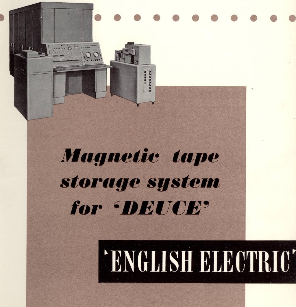
5 Magnetic tape storage for 'DEΠE' 1.0 GENERAL To augment the existing storage capacity of the mercury delay lines and the magnetic drum of DEUCE a magnetic tape auxiliary storage system is now available. The system is intended as an optional extra to DEUCE Mk.I and will no doubt be useful in many of the large scale technical and scientific calculations on which this computer is normally employed. However, it will usually form part of the DEUCE Mk. II when this computer is employed in its intended capacity as the central unit of a data processing system or as a combined commercial/scientific machine. This publication describes the main features of the magnetic tape system and is published to enable prospective users to assess its suitability for particular applications. 2.0 BASIC PRINCIPLES The storage medium is ½" wide magnetic tape in reels of up to 2400 feet each. The tape handling units are of the twin transporter type, i. e. two complete tapes and associated sets of sensing heads per unit. Up to four of these units (8 tapes) may be fitted to the DEUCE. The tapes can be run in either direction between their respective reels but only when the tape is running forward can writing and reading operations to and from the tape be performed. These operations are similar to those associated with the drum in that reading does not disturb the stored information whereas writing obliterates the information previously stored on that part of the tape. A magnetic tape carrying a single track, on which information appears in serial form, is uneconomic in equipment and has poor operating speed. The system therefore uses seven parallel tracks on the tape, six of which carry information. As the tape passes the reading or writing station, six binary digits of information are handled; this unit of information is termed a character and a six digit character is chosen to permit alpha-numeric recording (i.e. 0-9, A-Z and a number of symbols) with one recorded character representing one printed character. This allows convenient direct printing of alpha-numeric information from the tape using suitable apparatus and yet imposes no serious restrictions on the use of the tape for storage of binary information. 3 ES l4β
6 Transfer of information between the tape store and the computer is carried out, through a buffer store, in units of two DEUCE words (i.e. 64 binary digits). Since this unit is not an integral number of characters, alternative reading and writing instructions are provided which allow convenient transfer of binary, binary-coded decimal, or alpha-numeric information. To write binary information, two additional digits (both zero) are automatically added to the 64 digits of the buffer store, the resulting 66 digits being written on the tape as 11 characters. On reading the information back into the computer, the two added digits are automatically discarded and only the 64 digits required are available from the buffer store. f To write alpha-numeric information the 64 digits of a word pair must be made up of 10 alpha-numeric characters, each occupying six binary digits, followed by four non-significant digits which will not be recorded and which will be read back as zeros. Binary-coded decimal information may be transferred to and from the tape by either method, since only the four least significant digits of each character are needed for each decimal digit. Word pairs may be transferred continuously to or from the tape, the corresponding characters being recorded at a packing density (along the tape) of 80 per inch. Between blocks of information recorded in this manner, each consisting of any number of word pairs, a block gap is automatically provided by the process of stopping and re-starting the tape. These gaps are necessary to ensure that when a reading operation is required the tape has accelerated to its full speed before the first recorded character reaches the reading head. A group of blocks may be separated by a programmed operation from a subsequent group by a gap longer than the normal block gap. Such a group of blocks is termed a record and the reasons for its use are dealt with below. One of the double word length stores is used as the address to which information to and from the magnetic tape store is routed. 3.0 OPERATION The Magnetic Tape equipment is brought into operation automatically when the main computer equipment is switched on. Normally the first in a sequence of tape operations will be to select the tape deck on which the data is going to be handled. Once selected, all operations refer to that tape deck until another is selected, The select tape deck instruction turns on an interlock until 4 ES κβ
7 the change over of tape decks is completed thus preventing operation on a wrong tape deck before change-over is completed. An instruction is provided which causes the tape to rewind to a position from which it may operate on the first block of information on a reel. A maximum speed of five times the forward speed is reached at the middle of the rewind run. This instruction is interlocked until the rewind of the selected deck is started, after which the deck selection trigger is automatically cleared leaving rewind to proceed. Calling for this tape deck again will put on the interlock which will prevent anything being done to it until rewind has been completed. However, any other tape deck can be selected and operated during this time. Programmes must be arranged so that if any block is required to be altered, by a write instruction, all succeeding blocks of that record must also be rewritten up to the beginning of the next record gap. The length of the record gap must be fairly large and of a length which increases with the number of word pairs and block gaps in the record. This allows for the fact that, due to variation of tape speed and other causes, the precise length of tape occupied by a given number of word pairs and block gaps cannot be accurately controlled. Instructions are provided which move the tape from one block gap to the next block gap in either direction, also from one record gap to. the next again in either direction. When passing over the tape in either direction the end of the reel will be signalled by a warning device and the tape brought to rest. An earlier warning is included for programming purposes to give advance warning of 24 inches of recording left before the tape becomes inactive. Thus the programme detecting the approaching end of a tape while writing can arrange to restrict the final block length to less than 24 inches. This limit is the equivalent of 12 DL s of storage. 4.0 READING AND WRITING An initial instruction selecting the tape deck required operates 10 milliseconds before the information can be transferred to or from the magnetic tape buffer store. This period may be used for computation, if required, but if information is transferred before the termination of this period the transfer instruction will be interlocked and prevented from being obeyed until the lapse of the full 10mS. During reading, word pairs are assembled electronically and then as soon as they are completed, automatically transferred to the double word buffer store, from which transfers to the DEUCE can be made. The rate at which they appear is approximately one word pair every 1¼ milliseconds. 5
8 An interlock ensures that each word pair is only taken from the buffer store once. The tape stops automatically when a block gap is reached and becomes inactive. This inactive state may be sensed by the programme - a facility which is useful when it is not required to read all the word pairs in a block. < During writing, word pairs must be transferred to the Magnetic Tape buffer store by the programme every 1¼ milliseconds. An interlock ensures that no word pair can be placed in the buffer store until the previous one has been transferred. When word pairs cease to be placed in the buffer store the tape automatically stops, creating a block gap. f 5.0 PARITY CHECKING The tape system has lateral parity checking on each character and a longitudinal parity check character at the end of each block. The lateral parity check on a character is an extra digit on the seventh track which is a one if the number of digits in the character is even. The check on reading ensures that the number of ones laterally is odd. The longitudinal parity character at the end of a block has a one in a given digit position if the number of ones on the corresponding track in the block is odd. The check on reading therefore ensures that the number of ones in each track in a block is even. The parity checks are written automatically. At a suitable point in the programme, after each block has been read, a special instruction is used to check that no parity failure has occurred. 6.0 CONSTRUCTION The equipment is built into cubicles 4 0n wide x 3, 0" deep x 5 6" high. Each cubicle will house two tape decks and should be located conveniently to the Control Desk. 7.0 OPERATING SPEEDS The following information will enable an estimate to be made of the operating speed of the system in any particular application. Speed of tape when reading or writing 100 in./sec. Packing density of recorded information 80 chs./inch Length of block gap 2 in. Tape stopping time interlocks 10 msec. Tape starting time interlocks 10 msec. Maximum length of tape per reel 2,400 feet. Rewind time of complete 2,400 ft. spool 2-2⅛ minutes. 6 E8 14β


9 ENGLISH ELECTRIC r I THE ENGLISH ELECTRIC COMPANY LIMITED CONTROL AND ELECTRONICS DEPARTMENT KIDSGROVE - STOKE-ON-TRENT - STAFFS. Works: STAFFORD - PRESTON - RUGBY - BRADFORD - LIVERPOOL - ACCRINGTON Publication ES/146 Printed in England MPS
SECONDARY STORAGE DEVICES: MAGNETIC TAPES AND CD-ROM
 SECONDARY STORAGE DEVICES: MAGNETIC TAPES AND CD-ROM Contents of today s lecture: Magnetic Tapes Characteristics of magnetic tapes Data organization on 9-track tapes Estimating tape length requirements
GENERAL DESCRIPTION UNIVAC ~DD4 III MAGNETIC TAPE SYSTEM UP
 GENERAL DESCRIPTION UNIVAC ~DD4 III MAGNETIC TAPE SYSTEM The Magnetic Tape Unit for the UNIVAC 1004 I I I is provided as either a Single Magnetic Tape Unit or a Dual Magnetic Tape Unit. The Dual Magnetic
General description. The Pilot ACE is a serial machine using mercury delay line storage
 Chapter 11 The Pilot ACE 1 /. H. Wilkinson Introduction A machine which was almost identical with the Pilot ACE was first designed by the staff of the Mathematics Division at the suggestion of Dr. H. D.
Auxiliary states devices
 22 Auxiliary states devices When sampling using multiple frame states, Signal can control external devices such as stimulators in addition to switching the 1401 outputs. This is achieved by using auxiliary
April 1965 NUMBER OF COPIES: 75
 NATIONAL RADIO ASTRONOMY OBSERVATORY Green Bank, West Virgini. Electronics Division Internal Report No 47 INTERFEROMETER DIGITAL OUTPUT SYSTEM Claude C. Bare April 1965 NUMBER OF COPIES: 75 INTERFEROMETER
CONTROL DA T A 3228-A/B, 3229-A/B
 CONTROL DA T A 3228-A/B, 3229-A/B magnetic tape controllers Reference Manual REVISION REVISION RECORD DESCRIPTION A Manual released; this publication obsoletes the 3228-A/3229-A Magnetic 1'ane rontrollen::
A Terabyte Linear Tape Recorder
 A Terabyte Linear Tape Recorder John C. Webber Interferometrics Inc. 8150 Leesburg Pike Vienna, VA 22182 +1-703-790-8500 webber@interf.com A plan has been formulated and selected for a NASA Phase II SBIR
* This configuration has been updated to a 64K memory with a 32K-32K logical core split.
 398 PROCEEDINGS-FALL JOINT COMPUTER CONFERENCE, 1964 Figure 1. Image Processor. documents ranging from mathematical graphs to engineering drawings. Therefore, it seemed advisable to concentrate our efforts
SERIAL HIGH DENSITY DIGITAL RECORDING USING AN ANALOG MAGNETIC TAPE RECORDER/REPRODUCER
 SERIAL HIGH DENSITY DIGITAL RECORDING USING AN ANALOG MAGNETIC TAPE RECORDER/REPRODUCER Eugene L. Law Electronics Engineer Weapons Systems Test Department Pacific Missile Test Center Point Mugu, California
DIGITAL REGISTERS. Serial Input Serial Output. Block Diagram. Operation
 DIGITAL REGISTERS http://www.tutorialspoint.com/computer_logical_organization/digital_registers.htm Copyright tutorialspoint.com Flip-flop is a 1 bit memory cell which can be used for storing the digital
The ESRF Radio-frequency Data Logging System for Failure Analysis
 The ESRF Radio-frequency Data Logging System for Failure Analysis Jean-Luc REVOL Machine Division European Synchrotron Radiation Facility Accelerator Reliability Workshop 4-6 February 2002 Impact of the
Chapter 4. Logic Design
 Chapter 4 Logic Design 4.1 Introduction. In previous Chapter we studied gates and combinational circuits, which made by gates (AND, OR, NOT etc.). That can be represented by circuit diagram, truth table
Two crystal clocks are used to generate one of three character writing rates, depending on the density (200, 556, SOO) specified by the programmer.
 specified by the programmer.") The Automatic Magnetic Tape Control Type 57A, operating through nterface Logic, such as the 520, 521, or 522, transfers information between Programmed Data Processor-4 and up to eight tape transports.
The Automatic Magnetic Tape Control Type 57A, operating through nterface Logic, such as the 520, 521, or 522, transfers information between Programmed Data Processor-4 and up to eight tape transports.
Previous Lecture Sequential Circuits. Slide Summary of contents covered in this lecture. (Refer Slide Time: 01:55)
") Previous Lecture Sequential Circuits Digital VLSI System Design Prof. S. Srinivasan Department of Electrical Engineering Indian Institute of Technology, Madras Lecture No 7 Sequential Circuit Design Slide
Previous Lecture Sequential Circuits Digital VLSI System Design Prof. S. Srinivasan Department of Electrical Engineering Indian Institute of Technology, Madras Lecture No 7 Sequential Circuit Design Slide
chosen as the minimum that would provide a usable single-address order, in this case five binary digits for instruction and 11 binary
 Chapter 6 The Whirlwind I computer 1 R. R. Everett Project Whirlwind is a high-speed computer activity sponsored at the Digital Computer Laboratory, formerly a part of the Servomechanisms Laboratory, of
HELICAL SCAN TECHNOLOGY: ADVANCEMENT BY DESIGN
 HELICAL SCAN TECHNOLOGY: ADVANCEMENT BY DESIGN By Curt Mulder And Kelly Scharf Exabyte Corporation THIC Conference Del Mar, CA 1/20/98 1685 38 th Street Boulder, CO 80301 +1-303-442-4333 +1-303-417-7080
2. SUPERPATH Mbps Digital Service 2.1. General
 Page 1 Rates and charges for services explained herein are contained in Part M, Section 3, Service Charges referred to herein are explained in Part A, Section 3 and contained in Part M, Section 1. 2.1
APPROVED for connection to Telecommunication systems specified in the instructions for use subject to the conditions set out in them.
 TM COMSPHERE 3900 Series Modems Models 3910 and 3911 Government Requirements for Great Britain Document Number 3910-A2-GK42-10 November 1996 Overview This document highlights government requirements, safety
HSR-1 Digital Surveillance Recorder Preliminary
 HSR-1 Digital Surveillance Recorder Hybrid Technology - An Essential Requirement for High-Performance Digital Video Recording & Archiving Preliminary How do you rate your security Can it record as long
Practical Application of the Phased-Array Technology with Paint-Brush Evaluation for Seamless-Tube Testing
 ECNDT 2006 - Th.1.1.4 Practical Application of the Phased-Array Technology with Paint-Brush Evaluation for Seamless-Tube Testing R.H. PAWELLETZ, E. EUFRASIO, Vallourec & Mannesmann do Brazil, Belo Horizonte,
LINEAR DIGITAL RECORDER WITH 100 MBYTE/SEC HIPPI INTERFACE
 LINEAR DIGITAL RECORDER WITH 100 MBYTE/SEC HIPPI INTERFACE John C. Webber Interferometrics Inc. 14120 Parke Long Court Chantilly, VA 22021 (703) 222-5800 webber@interf.com SUMMARY A plan has been formulated
MODULE 3. Combinational & Sequential logic
 MODULE 3 Combinational & Sequential logic Combinational Logic Introduction Logic circuit may be classified into two categories. Combinational logic circuits 2. Sequential logic circuits A combinational
Six witnesses. Your choice.
 Surveillance VCR Catalogue 2001 Six witnesses. Your choice. this is not a rehearsal. www.sony-cctv.com CCIR / PAL Sony Surveillance VCR IN THE FIELDS of security and surveillance, video monitoring systems
PRINCIPLES AND APPLICATIONS
 GENERATION & NETWORK Digital Automation Measuring and Control Devices AMS7000 PROCOM The optimum operation of an electrical network depends particularly on the reliability and the availability of the protection,
Dr. Shahram Shirani COE2DI4 Midterm Test #2 Nov 19, 2008
 Page 1 Dr. Shahram Shirani COE2DI4 Midterm Test #2 Nov 19, 2008 Instructions: This examination paper includes 13 pages and 20 multiple-choice questions starting on page 3. You are responsible for ensuring
The Lincoln TX-2 Input-Output System*
 156 1957 WESTERN COMPUTER PROCEEDINGS The Lincoln TX-2 Input-Output System*, JAMES w. FORGIEt INTRODUCTION THE input-output system of the Lincoln TX-2 computer contains a variety of input-output devices
DM Segment Decoder/Driver/Latch with Constant Current Source Outputs
 DM9368 7-Segment Decoder/Driver/Latch with Constant Current Source Outputs General Description The DM9368 is a 7-segment decoder driver incorporating input latches and constant current output circuits
Flip Flop. S-R Flip Flop. Sequential Circuits. Block diagram. Prepared by:- Anwar Bari
 Sequential Circuits The combinational circuit does not use any memory. Hence the previous state of input does not have any effect on the present state of the circuit. But sequential circuit has memory
Half-Adders. Ch.5 Summary. Chapter 5. Thomas L. Floyd
 Digital Fundamentals: A Systems Approach Functions of Combinational Logic Chapter 5 Half-Adders Basic rules of binary addition are performed by a half adder, which accepts two binary inputs (A and B) and
Digital Representation
 Chapter three c0003 Digital Representation CHAPTER OUTLINE Antialiasing...12 Sampling...12 Quantization...13 Binary Values...13 A-D... 14 D-A...15 Bit Reduction...15 Lossless Packing...16 Lower f s and
FROM IRIG TO MICRO-TRACK THE EVOLUTION OF MULTI-TRACK DATA RECORDING. Edwin Kayes
 FROM IRIG TO MICRO-TRACK THE EVOLUTION OF MULTI-TRACK DATA RECORDING Edwin Kayes Penny & Giles Data Systems The Mill, Wookey Hole, Wells, BA5 1BB, England ABSTRACT This paper discusses practical examples
MUHAMMAD NAEEM LATIF MCS 3 RD SEMESTER KHANEWAL
 1. A stage in a shift register consists of (a) a latch (b) a flip-flop (c) a byte of storage (d) from bits of storage 2. To serially shift a byte of data into a shift register, there must be (a) one click
Development of an Abort Gap Monitor for High-Energy Proton Rings *
 Development of an Abort Gap Monitor for High-Energy Proton Rings * J.-F. Beche, J. Byrd, S. De Santis, P. Denes, M. Placidi, W. Turner, M. Zolotorev Lawrence Berkeley National Laboratory, Berkeley, USA
Block System Interface Requirements
 Block System Interface Requirements Synopsis This document mandates the requirements for block systems interfaces between signalling infrastructure and railway operations. Copyright in the s is owned by
DIGITIZING Pulse Duration Modulated
 no more than a few minutes. However, where data are being taken for very much longer periods of time, as would be the case in aircraft flight testing, several improvements are indicated, the most important
for Television ---- Formatting AES/EBU Audio and Auxiliary Data into Digital Video Ancillary Data Space
 SMPTE STANDARD ANSI/SMPTE 272M-1994 for Television ---- Formatting AES/EBU Audio and Auxiliary Data into Digital Video Ancillary Data Space 1 Scope 1.1 This standard defines the mapping of AES digital
JAMAR TRAX RD Detector Package Power Requirements Installation Setting Up The Unit
 JAMAR TRAX RD The TRAX RD is an automatic traffic recorder designed and built by JAMAR Technologies, Inc. Since the unit is a Raw Data unit, it records a time stamp of every sensor hit that occurs during
Single Axis Position Controller
 SERIES P9511 Single Axis Position Controller Compact Construction Simple Go-to operation Integrated Relay Output Integrated Mains Power Supply ELEKTRO-TRADING sp. Z o.o. 44-109 Gliwice, ul. Mechaników
Design and Use of a DTV Monitoring System consisting of DVQ(M), DVMD/DVRM and DVRG
, DVMD/DVRM and DVRG") Design and Use of a DTV Monitoring System consisting of DVQ(M), DVMD/DVRM and DVRG When monitoring transmission systems it is often necessary to control the monitoring equipment and to check the measurement
Design and Use of a DTV Monitoring System consisting of DVQ(M), DVMD/DVRM and DVRG When monitoring transmission systems it is often necessary to control the monitoring equipment and to check the measurement
with the decimal code to provide a decimal point and a space. The Inscriber
 T Auxiliary Equipment to SEAC HE two previous papers have been concerned principally with inputoutput units and equipment that is actually attached to the SEAC. That which is now described is physically
Module -5 Sequential Logic Design
 Module -5 Sequential Logic Design 5.1. Motivation: In digital circuit theory, sequential logic is a type of logic circuit whose output depends not only on the present value of its input signals but on
A MISSILE INSTRUMENTATION ENCODER
 A MISSILE INSTRUMENTATION ENCODER Item Type text; Proceedings Authors CONN, RAYMOND; BREEDLOVE, PHILLIP Publisher International Foundation for Telemetering Journal International Telemetering Conference
MILLITARY SPECIFICATION SHEET
 INCH-POUND MILLITARY SPECIFICATION SHEET 10 November 2000 SUPERSEDING MIL-R-6106/14B 10 March 1989 RELAY, ELECTRIC, PERMANENT DRIVE, 50 AMP, SPDT (DB) DOUBLE MAKE DOUBLE BREAK AUXILIARY CONTACTS (5 AMP),
FLIP-FLOPS AND RELATED DEVICES
 C H A P T E R 5 FLIP-FLOPS AND RELATED DEVICES OUTLINE 5- NAND Gate Latch 5-2 NOR Gate Latch 5-3 Troubleshooting Case Study 5-4 Digital Pulses 5-5 Clock Signals and Clocked Flip-Flops 5-6 Clocked S-R Flip-Flop
EET2411 DIGITAL ELECTRONICS
 5-8 Clocked D Flip-FlopFlop One data input. The output changes to the value of the input at either the positive going or negative going clock trigger. May be implemented with a J-K FF by tying the J input
Motion Video Compression
 7 Motion Video Compression 7.1 Motion video Motion video contains massive amounts of redundant information. This is because each image has redundant information and also because there are very few changes
Communicating And Expanding Visual Culture From Analog To Digital
 Home Video For The 21st Century Communicating And Expanding Visual Culture From Analog To Digital V I C T O R C O M P A N Y O F J A P A N, L T D. Introduction JVC (Victor Company of Japan, Ltd.) invented
Time-Lag Relays. User s Handbook (General Model)
") Time-Lag Relays User s Handbook (General Model) 651.601.387 Rev: V39 Date: 09/2016 Electrotécnica Arteche Smart Grid, S.L. This document, including texts, photos, graphics and any other content, is protected
Time-Lag Relays User s Handbook (General Model) 651.601.387 Rev: V39 Date: 09/2016 Electrotécnica Arteche Smart Grid, S.L. This document, including texts, photos, graphics and any other content, is protected
tape at the rate of ten characters per second.
 recorded, the forward card stop, under the control of its cam, opens. The curvature of the card around the drum causes the card, when released from the stop, to snap sharply against a set of guides which
Training Note TR-06RD. Schedules. Schedule types
 Schedules General operation of the DT80 data loggers centres on scheduling. Schedules determine when various processes are to occur, and can be triggered by the real time clock, by digital or counter events,
******************************************************************************** Optical disk-based digital recording/editing/playback system.
 Akai DD1000 User Report: ******************************************************************************** At a Glance: Optical disk-based digital recording/editing/playback system. Disks hold 25 minutes
Digital Logic Design: An Overview & Number Systems
 Digital Logic Design: An Overview & Number Systems Analogue versus Digital Most of the quantities in nature that can be measured are continuous. Examples include Intensity of light during the day: The
DM Segment Decoder/Driver/Latch with Constant Current Source Outputs
 7-Segment Decoder/Driver/Latch with Constant Current Source Outputs General Description The DM9368 is a 7-segment decoder driver incorporating input latches and constant current output circuits to drive
Installation Manual IPT Installation of skillet systems with 125 A track current. MV a-E.
 www.wampfler.com Page 1 of 27 Index Page 1 Basics...4 2 Basic understanding of an IPT -system...5 3 General rules regarding metal parts in close proximity...6 3.1 Envelope free of ferromagnetic material...6
THE OPERATION OF A CATHODE RAY TUBE
 THE OPERATION OF A CATHODE RAY TUBE OBJECT: To acquaint the student with the operation of a cathode ray tube, and to study the effect of varying potential differences on accelerated electrons. THEORY:
USER S MANUAL. FX2N-8AD Analog input block
 USER S MANUAL FX2N-8AD Analog input block FX2N-8AD Analog input block Foreword This manual contains text, diagrams and explanations which will guide the reader in the correct installation and operation
AE16 DIGITAL AUDIO WORKSTATIONS
 AE16 DIGITAL AUDIO WORKSTATIONS 1. Storage Requirements In a conventional linear PCM system without data compression the data rate (bits/sec) from one channel of digital audio will depend on the sampling
BISHOP ANSTEY HIGH SCHOOL & TRINITY COLLEGE EAST SIXTH FORM CXC CAPE PHYSICS, UNIT 2 Ms. S. S. CALBIO NOTES lesson #39
 BISHOP ANSTEY HIGH SCHOOL & TRINITY COLLEGE EAST SIXTH FORM CXC CAPE PHYSICS, UNIT 2 Ms. S. S. CALBIO NOTES lesson #39 Objectives: Students should be able to Thursday 21 st January 2016 @ 10:45 am Module
Note 5. Digital Electronic Devices
 Note 5 Digital Electronic Devices Department of Mechanical Engineering, University Of Saskatchewan, 57 Campus Drive, Saskatoon, SK S7N 5A9, Canada 1 1. Binary and Hexadecimal Numbers Digital systems perform
INTERNATIONAL STANDARD
 INTERNATIONAL STANDARD IEC 62447-1 First edition 2007-06 Helical-scan compressed digital video cassette system using 6,35 mm magnetic tape Format D-12 Part 1: VTR specifications Commission Electrotechnique
Technical Description Track-Control
 Technical Description Track-Control Uhlenbrock Elektronik GmbH Mercatorstraße 6 46244 Bottrop E-Mail: info@uhlenbrock.de Web: www.uhlenbrock.de TV 1.0. 17.09.2007 Track-Control 1. Overall Operation 1.1
Contents Circuits... 1
 Contents Circuits... 1 Categories of Circuits... 1 Description of the operations of circuits... 2 Classification of Combinational Logic... 2 1. Adder... 3 2. Decoder:... 3 Memory Address Decoder... 5 Encoder...
UNIT IV. Sequential circuit
 UNIT IV Sequential circuit Introduction In the previous session, we said that the output of a combinational circuit depends solely upon the input. The implication is that combinational circuits have no
TYPICAL QUESTIONS & ANSWERS
 DIGITALS ELECTRONICS TYPICAL QUESTIONS & ANSWERS OBJECTIVE TYPE QUESTIONS Each Question carries 2 marks. Choose correct or the best alternative in the following: Q.1 The NAND gate output will be low if
A computer-controlled system for the recording modification and presentation of two-channel musical stirnuli
 Behavior Research Methods & Instrumentanon 1976, Vol. 8(1), 24-28 COMPUTER TECHNOLOGY A computer-controlled system for the recording modification and presentation of two-channel musical stirnuli R. BIRD
(Refer Slide Time: 2:00)
") Digital Circuits and Systems Prof. Dr. S. Srinivasan Department of Electrical Engineering Indian Institute of Technology, Madras Lecture #21 Shift Registers (Refer Slide Time: 2:00) We were discussing
Digital Circuits and Systems Prof. Dr. S. Srinivasan Department of Electrical Engineering Indian Institute of Technology, Madras Lecture #21 Shift Registers (Refer Slide Time: 2:00) We were discussing
JAMAICA. Planning and development of audiovisual archives in Jamaica. by Anne Hanford. Development of audiovisual archives
 Restricted Technical Report PP/1988-1989/III.3.5 JAMAICA Development of audiovisual archives Planning and development of audiovisual archives in Jamaica by Anne Hanford Serial No. FMR/CC/CDF/120 United
Data Storage and Manipulation
 Data Storage and Manipulation Data Storage Bits and Their Storage: Gates and Flip-Flops, Other Storage Techniques, Hexadecimal notation Main Memory: Memory Organization, Measuring Memory Capacity Mass
RECOMMENDATION ITU-R BT Studio encoding parameters of digital television for standard 4:3 and wide-screen 16:9 aspect ratios
 ec. ITU- T.61-6 1 COMMNATION ITU- T.61-6 Studio encoding parameters of digital television for standard 4:3 and wide-screen 16:9 aspect ratios (Question ITU- 1/6) (1982-1986-199-1992-1994-1995-27) Scope
Chapter 3 Digital Data
 Chapter 3 Digital Data So far, chapters 1 and 2 have dealt with audio and video signals, respectively. Both of these have dealt with analog waveforms. In this chapter, we will discuss digital signals in
Contents INFORMATION FLOW TRACK - TRAIN
 2017-05-12 3. INFORMATION FLOW TRACK-TRAIN Page 1 (159) Chapter 3: INFORMATION FLOW TRACK - TRAIN Contents 3. INFORMATION FLOW TRACK - TRAIN 5 3.1 INTRODUCTION 5 3.1.1 Scope 5 3.2 INFORMATION FLOW TRACK
Zero Latency Monitoring Handbook
 Zero Latency Monitoring Handbook Z Monitoring or Zero Latency is supported as of Studio One 2.6 on the following interfaces: 1 P a g e Z Signal Paths Z On 1) Make sure the input track(s) are set to monitor.
RECOMMENDATION ITU-R BT (Questions ITU-R 25/11, ITU-R 60/11 and ITU-R 61/11)
") Rec. ITU-R BT.61-4 1 SECTION 11B: DIGITAL TELEVISION RECOMMENDATION ITU-R BT.61-4 Rec. ITU-R BT.61-4 ENCODING PARAMETERS OF DIGITAL TELEVISION FOR STUDIOS (Questions ITU-R 25/11, ITU-R 6/11 and ITU-R 61/11)
Rec. ITU-R BT.61-4 1 SECTION 11B: DIGITAL TELEVISION RECOMMENDATION ITU-R BT.61-4 Rec. ITU-R BT.61-4 ENCODING PARAMETERS OF DIGITAL TELEVISION FOR STUDIOS (Questions ITU-R 25/11, ITU-R 6/11 and ITU-R 61/11)
AC103/AT103 ANALOG & DIGITAL ELECTRONICS JUN 2015
 Q.2 a. Draw and explain the V-I characteristics (forward and reverse biasing) of a pn junction. (8) Please refer Page No 14-17 I.J.Nagrath Electronic Devices and Circuits 5th Edition. b. Draw and explain
Agenda. EE 260: Introduction to Digital Design Counters and Registers. Asynchronous (Ripple) Counters. Asynchronous (Ripple) Counters
 Counters. Asynchronous (Ripple) Counters") EE26: igital esign, Spring 28 4/8/8 EE 26: Introduction to igital esign ounters and Registers Yao Zheng epartment of Electrical Engineering University of Hawaiʻi at Mānoa Agenda ounters Introduction: ounters
EE26: igital esign, Spring 28 4/8/8 EE 26: Introduction to igital esign ounters and Registers Yao Zheng epartment of Electrical Engineering University of Hawaiʻi at Mānoa Agenda ounters Introduction: ounters
BLOCK CODING & DECODING
 BLOCK CODING & DECODING PREPARATION... 60 block coding... 60 PCM encoded data format...60 block code format...61 block code select...62 typical usage... 63 block decoding... 63 EXPERIMENT... 64 encoding...
ES-450J2 Universal 2 Channel Jog/Shuttle Remote
 ES-450J2 Universal 2 Channel Jog/Shuttle Remote Users Manual ES-450, ES-450J and ES-450J2 are trademarks of JLCooper Electronics. All other brand names are the property of their respective owners. ES-450J2
MODEL 2018 OPERATION MANUAL Firmware Version
 Reno A&E Telephone: (775) 826-2020 4655 Aircenter Circle Facsimile: (775) 826-9191 Reno, Nevada 89502 Internet: www.renoae.com USA e-mail: contact@renoae.com MODEL 2018 OPERATION MANUAL Firmware Version
Clash of cultures - Gains and drawbacks of archival collaboration
 Clash of cultures - Gains and drawbacks of archival collaboration I work in a folk music archive in a small regional institution in Rättvik, Sweden. Our region, Dalarna, has a rich tradition of folk music
DS1, T1 and E1 Glossary
 DS1, T1 and E1 Glossary Document ID: 25540 Contents Introduction Prerequisites Requirements Components Used Conventions T1/E1 Terms Error Events Performance Defects Performance Parameters Failure States
THE OPERATION OF A CATHODE RAY TUBE
 THE OPERATION OF A CATHODE RAY TUBE OBJECT: To acquaint the student with the operation of a cathode ray tube, and to study the effect of varying potential differences on accelerated electrons. THEORY:
High Performance Carry Chains for FPGAs
 High Performance Carry Chains for FPGAs Matthew M. Hosler Department of Electrical and Computer Engineering Northwestern University Abstract Carry chains are an important consideration for most computations,
Operating Instructions
 Operating Instructions HAEFELY TEST AG KIT Measurement Software Version 1.0 KIT / En Date Version Responsable Changes / Reasons February 2015 1.0 Initial version WARNING Introduction i Before operating
The Provincial Archives of Alberta. Price List
 The Provincial Archives of Alberta Price List Effective: March 2016 Provincial Archives of Alberta staff reserves the right to have conditions on the completion of orders; the size of the order, copyright
Proposed SMPTE Standard SMPTE 425M-2005 SMPTE STANDARD- 3Gb/s Signal/Data Serial Interface Source Image Format Mapping.
 Proposed SMPTE Standard Date: TP Rev 0 SMPTE 425M-2005 SMPTE Technology Committee N 26 on File Management and Networking Technology SMPTE STANDARD- 3Gb/s Signal/Data Serial Interface Source
9691 COMPUTING. 9691/12 Paper 1 (Written Paper), maximum raw mark 75
, maximum raw mark 75") CAMBRIDGE INTERNATIONAL EXAMINATIONS GCE Advanced Subsidiary Level and GCE Advanced Level MARK SCHEME for the May/June 23 series 969 COMPUTING 969/2 Paper (Written Paper), maximum raw mark 75 This mark
CAMBRIDGE INTERNATIONAL EXAMINATIONS GCE Advanced Subsidiary Level and GCE Advanced Level MARK SCHEME for the May/June 23 series 969 COMPUTING 969/2 Paper (Written Paper), maximum raw mark 75 This mark
THE INSTITUTION OF ELECTRICAL ENGINEERS FOUNDED INCORPORATED BY ROYAL CHARTER 1921
 THE INSTITUTION OF ELECTRICAL ENGINEERS FOUNDED 1871. INCORPORATED BY ROYAL CHARTER 1921 SAVOY PLACE, LONDON. W.C.2 UNIVERSAL HIGH-SPEED DIGITAL COMPUTERS: A SMALL-SCALE EXPERIMENTAL MACHINE By F. C. WILLIAMS,
Installation / Set-up of Autoread Camera System to DS1000/DS1200 Inserters
 Installation / Set-up of Autoread Camera System to DS1000/DS1200 Inserters Written By: Colin Langridge Issue: Draft Date: 03 rd July 2008 1 Date: 29 th July 2008 2 Date: 20 th August 2008 3 Date: 02 nd
8/30/2010. Chapter 1: Data Storage. Bits and Bit Patterns. Boolean Operations. Gates. The Boolean operations AND, OR, and XOR (exclusive or)
") Chapter 1: Data Storage Bits and Bit Patterns 1.1 Bits and Their Storage 1.2 Main Memory 1.3 Mass Storage 1.4 Representing Information as Bit Patterns 1.5 The Binary System 1.6 Storing Integers 1.8 Data
Chapter 1: Data Storage Bits and Bit Patterns 1.1 Bits and Their Storage 1.2 Main Memory 1.3 Mass Storage 1.4 Representing Information as Bit Patterns 1.5 The Binary System 1.6 Storing Integers 1.8 Data
FX-2DA SPECIAL FUNCTION BLOCK USER'S GUIDE
 FX-2DA SPECIAL FUNCTION BLOCK USER'S GUIDE JY992D52801C This manual contains text, diagrams and explanations which will guide the reader in the correct installation and operation of the FX-2DA special
Rec. ITU-R BT RECOMMENDATION ITU-R BT * WIDE-SCREEN SIGNALLING FOR BROADCASTING
 Rec. ITU-R BT.111-2 1 RECOMMENDATION ITU-R BT.111-2 * WIDE-SCREEN SIGNALLING FOR BROADCASTING (Signalling for wide-screen and other enhanced television parameters) (Question ITU-R 42/11) Rec. ITU-R BT.111-2
1. General principles for injection of beam into the LHC
 LHC Project Note 287 2002-03-01 Jorg.Wenninger@cern.ch LHC Injection Scenarios Author(s) / Div-Group: R. Schmidt / AC, J. Wenninger / SL-OP Keywords: injection, interlocks, operation, protection Summary
Chapter 8 Functions of Combinational Logic
 ETEC 23 Programmable Logic Devices Chapter 8 Functions of Combinational Logic Shawnee State University Department of Industrial and Engineering Technologies Copyright 27 by Janna B. Gallaher Basic Adders
The Cathode Ray Tube
 Lesson 2 The Cathode Ray Tube The Cathode Ray Oscilloscope Cathode Ray Oscilloscope Controls Uses of C.R.O. Electric Flux Electric Flux Through a Sphere Gauss s Law The Cathode Ray Tube Example 7 on an
RECOMMENDATION ITU-R BR.716-2* (Question ITU-R 113/11)
") Rec. ITU-R BR.716-2 1 RECOMMENDATION ITU-R BR.716-2* AREA OF 35 mm MOTION PICTURE FILM USED BY HDTV TELECINES (Question ITU-R 113/11) (1990-1992-1994) Rec. ITU-R BR.716-2 The ITU Radiocommunication Assembly,
Rec. ITU-R BR.716-2 1 RECOMMENDATION ITU-R BR.716-2* AREA OF 35 mm MOTION PICTURE FILM USED BY HDTV TELECINES (Question ITU-R 113/11) (1990-1992-1994) Rec. ITU-R BR.716-2 The ITU Radiocommunication Assembly,
North Shore Community College
 North Shore Community College Course Number: IEL217 Section: MAL Course Name: Digital Electronics 1 Semester: Credit: 4 Hours: Three hours of Lecture, Two hours Laboratory per week Thursdays 8:00am (See
CNV-ALT. Introduction. 1 Features. Serial altitude to parallel Gillham code converter for mode C transponders. Operating Manual English 1.
 CNV-ALT Serial altitude to parallel Gillham code converter for mode C transponders Operating Manual English 1.00 Introduction The CNV-ALT accepts RS232 or Airtalk serial data from a compatible MGL Avionics
Math: Fractions and Decimals 105
 Math: Fractions and Decimals 105 Many students face fractions with trepidation; they re too hard, I don t understand. If this is you, there is no better tool to bring yourself back up to speed than a tape
DM Segment Decoder Driver Latch with Constant Current Source Outputs
 DM9368 7-Segment Decoder Driver Latch with Constant Current Source Outputs General Description The DM9368 is a 7-segment decoder driver incorporating input latches and constant current output circuits
Operating Instructions
 CNTX Contrast sensor Operating Instructions CAUTIONS AND WARNINGS SET-UP DISTANCE ADJUSTMENT: As a general rule, the sensor should be fixed at a 15 to 20 angle from directly perpendicular to the target