INTRODUCTION... 4 BEFORE YOU BEGIN... 6 ABOUT THIS MANUAL... 6 OTHER IMPORTANT NOTES... 7 QUICK GUIDE... 8 IF YOU JUST WANT TO GET GOING...
|
|
|
- Felicity Flynn
- 5 years ago
- Views:
Transcription

1 1
2 INTRODUCTION... 4 BEFORE YOU BEGIN... 6 ABOUT THIS MANUAL... 6 OTHER IMPORTANT NOTES... 7 QUICK GUIDE... 8 IF YOU JUST WANT TO GET GOING... 8 BASIC OPERATION... 9 MOUNTING YOUR PAM PICO... 9 POWER SUPPLY... 9 NAVIGATION... 9 SLIDING WINDOWS AND VIEWS MENU NAVIGATION THE PRESET AND QUICK SETUP STEP 1- PRESET LIST STEP 2 - INPUT AND CHANNEL ORDER STEP 3 - SCALE AND LOUDNESS SETUP STEP 4 - METER TEXT READ OUT TIME SOURCE INTERNAL OR SMPTE HOW TO BACKLIGHT AND STANDBY METER VIEWS AN OVERVIEW PORTRAIT BARGRAPH (VIEW 1) GRAPHICAL LOUDNESS PORTRAIT (VIEW 2) HORIZONTAL GRAPHICAL LOUDNESS (VIEW 3) PICTURE PREVIEW - SDI ONLY (VIEW 4) MSD VIEW MODE (VIEW 5) FFT MODE (VIEW 6) HORIZONTAL BARGRAPH (VIEW 7) METER SETUP & AUDIO ROUTING AUTOMATED METER SETUP CLOCK SETUP AND HIERARCHY AUDIO ROUTING SETUP THE ADVANCED SETUP MENU THE SETUP MENU ABOUT USER MODE & USER RESTRICTIONS PRESET FOLDER MATRIX OUTPUT ASSIGN SELECTING YOUR METER SOURCE METER SETUP STARFISH SETUP LOUDNESS PRESET LOUDNESS SETUP LOUDNESS OPTION LABELS ASSIGN AUDIO GLOBAL INSTRUMENTS & DISPLAY TOOLS PORTRAIT BARGRAPHS EYE WIDTH AES LOCK INDICATION GONIOMETER VECTORSCOPE
3 PHASE CORRELATION STARFISH JELLYFISH LOUDNESS BARGRAPH(S) METER TEXT READ-OUTS RECLAIM FACTOR GRAPHICAL LOUDNESS FFT SPECTRUM ANALYZER MOVING COIL EMULATION PICO LOGGING PC APPLICATION HOW TO HOW TO GET LANDSCAPE AND MSD VIEW HOW TO ENABLE FFT SPECTRUM ANALYZER HOW TO SET ANALOG INPUT SENSITIVITY HOW TO SWITCH TO MOVING COIL EMULATION HOW TO CHANGE THE BARGRAPH WIDTH HOW TO CUSTOMIZE WINDOW TEXT READ OUT HOW TO SOFTWARE UPDATE HOW TO CLONE THE SETTINGS FROM ONE UNIT TO ANOTHER HOW TO VIEW TWO STEREO PAIRS WHILE WATCHING LOUDNESS BASED ON PAIR # LOUDNESS & TERMINOLOGY ABOUT LOUDNESS TERMINOLOGY OTHER RELEVANT INFO PAM PICO ONLINE APPLICATION (PC SOFTWARE) SIGNAL CONNECTIONS SPECIFICATIONS
4 SAFETY Installation Unless otherwise stated TSL equipment may be installed at any angle or position within an operating - All TSL equipment conforms to the EC Low Voltage Directive: EC Low Voltage Directive (73/23/EEC)(OJ L )(LVD). Amendment: (93/68/EEC) (OJ L ). In all cases the frame of the equipment must be earthed on installation. Where appropriate, the earth pin on the IEC mains inlet connector is connected to the metal frame of the equipment, to 0 volts on the internal DC PSU and to signal ground unless otherwise stated. All metal panels are bonded together. Check that the voltage selector setting (if fitted) and the fuse rating is correct for the local mains supply. Due consideration for cooling requirements must be given when mounting the equipment. It is recommended that a 1RU of rack space, or a vent panel, should be left above and below the unit. Warranty, Maintenance and Repair All TSL products have a one year warranty period starting from the date it leaves the factory. A repair warranty is to apply. That is, the product is to be returned for repair with no replacement and an exchange shipping policy is also to apply. TSL offers a seven day DOA policy together with an exchange shipping policy. That is, if a product has been declared dead on arrival within a seven day period a warranty replacement will be shipped. A temporary replacement may be available where, for operational reasons, it is imperative that service is continued. The customer will be asked to enter into a loan agreement for the duration of repair. All faulty equipment returned to TSL for repair will, where possible, be returned to the customer within seven working days. TSL Returns Procedure Please telephone +44 (0) (Fax: +44 (0) ) and ask for Customer Support, detailing the model and serial number of the equipment, who will provide a Returns Number. This will enable us to track the unit effectively and will provide some information prior to the unit arriving. For each item, this unique Returns Number must be included with the Fault Report sent with the unit. A contact name and telephone number are also required with the Fault Report sent with the unit. Fault report details required. Company: Name: Address: Contact Name: Telephone number: Fax number: address: Returns Number: Symptoms of the fault (to include switch setting positions, input signals etc) 4
5 Packing Please ensure that the unit is well packed as all mechanical damage is chargeable. TSL recommends that you insure your equipment for transit damage. The original packaging, when available, should always be used when returning equipment. If returned equipment is received in a damaged condition, the damage should be reported both to TSL and the carrier immediately. 5


6 INTRODUCTION Before you begin Thank you for purchasing one of the PAM PiCo family members. With the PAM PiCo you are well equipped to meet the growing challenges within Audio and Loudness metering. The PAM PiCo complies with all major Broadcast loudness standards and delivers outstanding metering precision and clear read-outs, not merely on Loudness, but across the full range of audio metering tools. The PAM PiCo toolset makes it application-fit for any audio and loudness setup in broadcast, film & post production as well as live transmission and recording. With the clear PAM PiCo readout and compliance in your line of sight, you are always safe and sound. The PAM PiCo Family The PAM PiCo range has three family members, all including the complete TSL Products audio metering suite of tools. The difference between models is primarily in the number of display channels and I/O formats available. Here is a quick overview of the family members: About this manual This manual will provide you with a quick overview of the PAM PiCo operation, tools and options, as well as an in-depth look at the more advanced parameters and facilities of PAM PiCo. Happy reading! Please note: TSL Products reserve the rights to change the content of this manual at any time. The latest revision of this manual can be downloaded from: 6
7 Other Important Notes Disclaimer No part of this document may be reproduced or transmitted in any form or by any means, electronic or mechanical, including photocopying and scanning, for any purpose, without the prior written consent of TSL Products. The company aims to ensure that all details in this document are correct at the time of publication, but reserves the right to alter specifications and equipment without notice. The latest version will be available upon request. This publication is for international usage. Despite considerable effort to produce up to date information, no literature published by the company nor any other material that may be provided should be regarded as an infallible guide to the specifications available nor does it constitute an offer for sale of any particular product. StarFish and JellyFish are registered trademarks of DK Technologies. Dolby E is a registered trade mark of Dolby Laboratories, Inc. The ownership of any trademarks referenced is acknowledged. Purpose Any fitness for purpose legislation or other determination that may be applied in the area where this equipment is installed must take due cognisance that it is designed for use in professional broadcast, audio and video systems by appropriately trained personnel. The equipment is not intended for use in a domestic environment and regulations designed for such situations are not applicable. After sales modifications Any modifications to the equipment not specifically authorised and approved by TSL Products may invalidate the equipment warranty. This includes changes to cabling and variations to the recommended installation as detailed in the documentation issued by TSL Products. Modifications can invalidate EMC and safety features designed into this equipment and the manufacturer cannot be liable for any legal proceedings or problems that may arise relating to such modifications. No sales agent or other person involved in the supply chain is permitted to authorise variations from the content of this documentation. Important Safety Instructions Read these instructions. Study carefully and understand all safety and operating instructions before you install and operate the unit! Keep these instructions. Keep all safety and operating instructions for future reference! Heed all warnings on the unit and in the safety and operating instructions before you install and operate the unit! Follow all instructions to ensure against injury to yourself and damage to the unit or other objects connected to the unit. To prevent possible electrical shock, death, fire, injuries and malfunctions, use this product only as specified. Only use attachments and accessories specified by the manufacturer. The units of the PAM PiCo range are designed for indoor use only 7

8 Quick guide If you just want to get going If you just want to get going with your new PAM PiCo right away, here are a few simple steps to get it up and running. 1. Connect the included power supply or power your meter directly from your computer USB port. 2. Powering up your meter, you will see the on-board quick setup guide if you want to disregard that, slide across the three touch buttons from left-to-right (you can always return to the guide later). 3. Connect the PAM PiCo AES 1, 2 & 3 to the appropriate audio output and play audio. 4. Sliding further to the left, you will see a number of different views of PAM PiCo. Below is a quick overview of the different metering tools: For more information on the individual tools, please refer to the display tools and options section of this manual. 8

9 Basic Operation Mounting your PAM PiCo The PAM PiCo is supplied with an adjustable mounting bracket. The top piece is mounted onto the PAM PiCo with the two included screws, while the desktop piece is mounted with four screws. Additional fixing options and mounts are available from TSL Products.com or from RAM on The included model number is: RAP-B-138U Note: When fixing the mounting plate to the rear of the meter, use only the screws supplied damage may be caused by using longer screws, or different mounting back plate. Power Supply The PAM PiCo comes with a plug-top power supply with a USB outlet. If being used in conjunction with a computer or USB hub, any conventional USB-A outlet with the standard USB 5 volt supply may be used instead of the included power supply unit. This elegant feature not only makes the PAM PiCo easier to bring along, but also conveniently allows the PAM PiCo to power up with the relevant computer of your setup. Navigation The general navigation on the PAM PiCo is achieved through the three capacitive touch sensitive buttons below the screen. Each touch button corresponds to the on-screen button and dynamically changes name as relevant. In addition, swiping across the three buttons from left-to-right or vice versa, allows you to change the overall meter view or selected menu. 9

")

, the three touch buttons become your navigation.")
10 Sliding Windows and Views The sliding function described above allows you to easily move from one meter setup to another, as well as entering the background Quick setup, preset and Setup menus. You will find both the Quick Setup and Advanced Setup menu on either ends of the views in Portrait and Horizontal mode respectively. Adv. Setup Horizontal Quick Setup Horizontal Horizontal Views Portrait Views Quick Setup Portrai Advanced Setup Portrait View7 Horizontal Bargraph View6 FFT View5 MSD View View4 Picture Preview (SDI only) View3 PPM + Loudness History View2 PPM + Loudness History View1 PPM + Loudness PAM PiCo holds up to 7 different metering views, of which most allows further customization by you. Sliding from right to left will move from Portrait layouts into the horizontal view section. Go ahead and find the view that suites you. See more details about the individual meter views in the Meter View Section of this manual. Menu Navigation When inside a menu (Quick setup or Advanced setup), the three touch buttons become your navigation. The left most button moves the cursor up, the center button moves the cursor down and the right most button becomes a select function. At any point is it possible to slide across the buttons to exit the current menu. In several of the menus, a folder structure has been designed to hold the many parameters and functions of the PAM PiCo. To open or close a folder, move the cursor on top of the folder and press select. You are now exposed to the folders inside, including potential sub-folders. Tip: Selecting an empty line and hitting Select will close the current folder. 10

.")
11 The Preset and Quick Setup When powering up your meter for the first time, the Preset and Quick Setup menu will be shown as the first display. The Preset and Quick Setup menu, allows for a simplified and fast way of setting up you PAM PiCo. More advanced settings and functions are edited in the Setup menu reached by sliding from right to left. Note: The power-up showing of the Quick Start Guide may be disabled by unchecking the Show this panel on power up parameter (the change is stored upon exiting to the meter viewings). The Quick Start Guide will give you a few basic tips on operation and setting up your meter. Here are the four simple steps to follow to set your meter up in a few minutes: Step 1 Preset Select the preset you want to work with Step 2 Input Selection Select your preferred input and choose your desired Loudness Bargraph Step 3 Scale and Loudness Setup Select your Scale and Loudness setup of choice Step 4 Meter Text Read Out Define what four parameters you want to see on the Meter Text Read Out. Step 1- Preset List The PAM PiCo holds a list of presets that allows you a fast starting point, as well as showcasing some of the different tools included in the Meter. Any of the presets can be edited to become a custom user preset. Selecting a preset is as easy as moving the cursor to the desired preset on the list and hitting the Select button. PAM PiCo always has a preset selected and changes are instantly stored upon exiting to the Meter view, be it; meter setup, background parameters and display appearance. Dynamic preset naming When advancing in the Quick Setup, the selected preset name will dynamically reflect your choices. The dynamic preset name includes the following information: Input Source channel count and Order Loudness Setup Scale 11

12 Dynamic Preset Example Digital Input 5.1 Surround LCR Integrated channel order Loudness Bargraph R128 Loudness Setup LEQM Meter scale The naming of a preset may be customized in the Advanced Setup Menu under the Audio Global/Preset Folder (see more in the Setup Menu section). Step 2 - Input and Channel Order The Input and Channel Order section allows you to easily select both your preferred input source and the order of the incoming channels. The list of input and channel order only displays inputs and channel setups allowed by the current meters specific hardware and software configuration. More advanced input and channel routings may be accessed in the Advanced Setup Menu. The following inputs may appear depending on your specific Meters ability and interfaces: Analogue Digital De-embed All interfaces may be selected as 2.0, while only Digital and De-Embedded allows for 5.1 setups. 5.1 setups allow for two different channel orders: LRC corresponding to the EBU channel order: Left, Right, Center, LFE, Ls, Rs LCR corresponding to the SMTPE channel order: Left, Center, Right, Ls, Rs, LFE Choosing User Def will make the meter fall back on the settings of the more advanced Setup menu, allowing you to tailor input source and channel order in more advanced ways than those offered in the Quick Setup. Step 3 - Scale and Loudness Setup This menu allows you to define exactly what scale and specs your bar graphs should perform to. Select the desired scale by moving the cursor in place and hit Select. The scale list includes: Any scale will be applied to the chosen Meter view. However, one scale stands out and IEC 268 I BBC IEC 268 II IIB IEC 268 II DIN SMPTE VU FBTV DIN NBC Ultra VU LEQM RMS LEQ ITU RMS LEQ DMU1 DMU1630 DMU2 DMU A Dorrough 40C Dorrough EBU IEC Web Peak PPM4 Loud 10 12

13 Graphical Bargraph Width The graphical width of the Bargraphs may be altered. If set to Auto, the Meter will dynamically adapt the width. Selecting Normal will allow you to manually define the width in the Setup Menu. Please see the Setup Menu section for further details on the Normal or manual width definition. Loudness Setup The Loudness setup parameter allows you to select between a number standardized or recommended Loudness settings including: R128 ATSC A/85 LEQM BCAP TV2 DK ABC-TV LA HRTV-23FS ARIB AGCOM 219 If you select User the loudness setup may be completely customized to exactly your specifications in the Setup Menu. Please see the Setup Menu section for further details on the Normal or manual width definition. NOTE: The Loudness Capture mode may be set to automatic or manual. The Default setting is Auto and initiates the Loudness measurement when incoming audio passes the above a -70dBFS threshold. Please refer to Advanced Setup Menu/Loudness Setup/Capture for more information Loudness Bar Type Allows you to define if you want to see a Loudness bar next to your other Bar graphs and if so, what Loudness parameter will be indicated: Momntry Momentary Loudness Shorttrm Short-term Loudness Integrt Integrated Loudness None Meaning no Loudness Bar graph displayed. Momentary+Shorttrm Dual Loudness bars of both Momentary and Short-term Loudness Step 4 - Meter Text Read Out The Meter Text Read Out allows you to customize what parameter each of the four Text read outs in the top the PAM PiCo screen displays. Each of the four parameters has its own folder with the parameters that are possible to display as a Text Read out. Line 1 Line 2 Line 3 Line 4 13

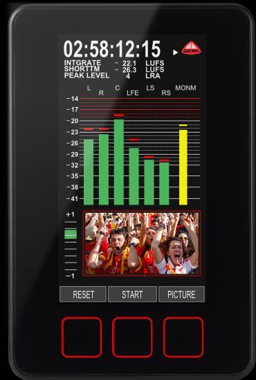
14 Time Source Internal or SMPTE When tracking loudness levels, it is essential to have a time base. PAM PiCo includes its own arbitrary time, starting from 00 for every time a new Loudness measurement is initiated and continued until Stop or Reset is pressed. Additionally, PAM PiCo features the ability to read, view and log against an external SMPTE or LTC timecode. The Time Source Parameter determines whether you want to use the internal PAM PiCo time or external SMPTE time code. SMPTE time code must be input into the Right Analogue channel in order for PAM PiCo to read the time. The time code may be display as one of the four Text Read outs available in any of the PAM PiCo views and is also viewed in the MSD View (View 5). How to The Quick Setup features a few How to... descriptions. Please refer to the complementary How to section of this manual for a detailed description and tips on how to perform specific tasks using the PAM PiCo. Backlight and Standby The backlight parameter allows you to set the brightness of your meter. Hit the Select button and use arrow up/down to set the desired backlight level. De-select the backlight parameter by hitting Select again. The Standby parameter enables the meter to be put into standby mode. Hit any of the three touch sensitive buttons to wake up your meter. Meter Views an Overview This section gives you a quick overview of the different views available in the Portrait Bargraph (View 1) The Portrait bargraph view features a number simultaneous viewings and readouts. The default functions of this view include 4 text readouts at the top, level bargraphs and the option of adding phase and vectorscope at the bottom of the view. The Loudness indication may be a single or dual bargraph, allowing for two different loudness parameters to be viewed at the same time. In addition to the traditional bargraphs, this view also has the ability to show level and loudness as moving coil emulations. The moving coil emulation may be changed here: Adv. Setup/Preset/Meter Setup/Display mode Finally, the SDI capable models, allows for Picture Preview of the incoming video stream. 14


15 Graphical Loudness Portrait (View 2) The graphical loudness view, allows for several different simultaneous views. On top of the four standard text readouts and phase meter, it features level bargraphs adhering to the defined scale, while the dual Loudness bars are referring to the defined loudness scale. In essence, this means that two independent scales are viewed at the same time. Furthermore, the Loudness level is plotted against time as a graphical track on screen, allowing for a historical view. Loudness may also be logged via the PC application against either internal time or external SMPTE time code. Horizontal Graphical Loudness (View 3) The horizontal graphical loudness view features a similar set of option as the portrait version of this view. Additionally, four more text readouts may be defined on the top right section of the screen. The specific parameters view may be changed here: Adv. Setup/Preset/Loudness Option/Window Text Picture Preview - SDI only (View 4) The Picture Preview feature is available on the SDI capable only. This feature allows you to tap into the 3G SDI video stream and comes in very handy when wanting to verify that you are monitoring the correct SDI stream. The Picture Preview feature is also available in the Portrait Bargraph mode (View1). In the View 1, the Picture Preview may be toggled on/off by hitting the Picture button. MSD View mode (View 5) The MSD View builds on the heritage of the famous TSL Products MSD meter range and features a Vectorscope alongside a bargraph section allowing for both level and loudness views. In addition, the four text readouts are displayed on the upper right section of the screen. In addition to the regular meters and read-outs, the MSD View features a Time code display below the StarFish, which allows you to follow either the internal timecode used during Loudness tracking or external SMPTE time code. The choice of time source may be set in the Quick Setup menu. 15

 The FFT view simply features a 1024 band")

16 As an extra option, the MSD View may be changed to display moving coil emulations instead of bargraphs. The moving coil emulation may be changed here: Adv. Setup/Preset/Meter Setup/Display mode The Moving Coil Dual mode allows you the ultra-wide Moving Coil instrument displaying left and right channel in the same instrument FFT mode (View 6) The FFT view simply features a 1024 band FFT spectrum analyzer. Please check out the Instrument & Display tools section of this manual for further information specifically on this tool. Horizontal Bargraph (View 7) The Horizontal bargraph view, in addition to the regular Text readouts, vectorscope and phase meter, features a horizontal bargraph view. 16


17 Meter Setup & Audio Routing Automated Meter Setup As you are probably aware by now, the PAM PiCo is quite a complex piece of equipment. In order to simplify setup, the PAM PiCo has an integrated auto setup function that ensures that Bargraphs, loudness, vectorscope and other instruments has pre-wired inputs. For example; the Bargraphs will automatically position Left and Right channel as the first two Bargraphs and then route them onto the phase correlation meter. Essentially this means that outside the initial input to the Bargraphs, the routing in between the different instruments inside the PAM PiCo is fixed and cannot be altered. Clock Setup and Hierarchy PAM PiCo always attempts to lock to the relevant input source, but also has an internal lock hierarchy initially looking for a valid clock on SDI, AES and finally internal clock. This means that if you are using SDI inputs, PAM PiCo will look for clock on the respective inputs, similarly with AES inputs (clock will be derived from AES1). If no valid lock is found, PAM PiCo will fall back on its internal 48kHz clock. Hierarchy PAM PiCo attempts to lock onto clocks in the following order: 1. SDI Audio Routing Setup 2. AES1 3. Internal The audio routing of the PAM PiCo is highly flexible and allows for a high degree of customization. All of the following is automatically handled by the Quick Setup, allowing you to focus on what is important - the Audio. However, if you need to customize routing or labeling of input channels or something else, here is what you need to know (fig xx): Source Selection (Advanced Setup; Matrix Output Assign, Meter) The basic routing and connection between inputs and instruments is handled in the Matrix Output Assign folder in the Advanced Setup menu. Sources are selected from an instrument or Role point of view e.g. selecting the first role (fig xx: 17:L), you are enabled to select the appropriate source on the left hand side of the menu (L DIG). Hitting the Select button twice will bring up the Source list that you can choose from. Source List The Source list will display every available source of your meter including a number of internal sources with special functions that we will get back to. This means that if your meter has de-embedded SDI channels, you will see these, just like digital and analogue sources will show if enable on your meter. 17

 signal in MS viewings, or as Right ch.")
18 Internal Sources As mentioned, the Meter includes a number of internal sources that has specific functions like Off, Sum, Difference, Loudness etc. These come handy for setting up special functionality like a Loudness Bargraph, or adding MS viewing to the Moving Coil emulation. Here is a list of the internal sources function: Internal Source Off Off TonL TonR Mix Diff Loud Function Off Off For internal use For internal use Used for Sum (M) signal in MS viewings, or as Left ch. when in Downmix mode Used for Diff (S) signal in MS viewings, or as Right ch. when in Downmix mode For Loudness Bar Source Labels (Input) (Advanced Setup; Labels Assign, Input) The Meter includes a list of default names/labels for all the available sources. However, these may be changed completely to your liking. This comes in handy when you want to label your sources with more relevant names e.g. L OB Van or TV1 or what-ever is relevant for you. The Source Labels menu allows you to do exactly that. In the Advanced Setup menu, select the Labels Assign folder, go to Input and select the source you want to re-label. Now choose the label you prefer from the Global Label Master. Channel Role Label (Output) (Advanced Setup; Labels Assign, Output) Similar to the Source Labeling the channel Role may be re-labeled as well. This is the label that is indicated on display above the relevant Bargraph. In the Advanced Setup menu, select the Labels Assign folder, go to Output and select the role you want to re-label. Now choose the label you prefer from the Global Label Master. Please note that the Automated Meter Setup function relies on certain roles to avails be labeled correct e.g. Left, Right, Center, LFE, Ls, Rs are all used to setup the StarFish correctly. Global Label Master (Advanced Setup; Audio Global, Labels, Signal) The Global Label Master is a default list of all the labels available for Source and Channel Role labeling. Each of the Master labels may be altered to your liking, meaning that you can completely customize the labeling of both incoming sources and roles. Audio Routing parameters included in preset 18


19 All of the above outlined audio routing and re-label functions are stored instantly in the current preset, with the Global Label Master as the only exception. This means that your routing and labeling may be completely altered by the flick of a preset change, while the Global Label Master stays fixed independent of preset changes. 19
20 The Advanced Setup Menu The Setup Menu The Setup Menu holds the access to all of the background parameters of your PAM PiCo. In order to understand the functionality, it is important for you to read through the different sections. Many of the parameters will alter preset parameters and hence are instantly stored. Therefor it might be relevant to select the desire preset to be edited before proceed with customizing your meter setting in the Setup Menu. NOTE: If you are looking to change a specific feature or function it might be relevant to look at some of the examples in the How to section of this manual. About User Mode & User Restrictions PAM PiCo has four levels of user access, allowing for the meter to be protected against unintended use and changes to the setup. The four levels are: - Restricted - Basic - Full - Administrator (default) Changing the User mode Changing the user mode takes effect at the first store after exiting the Advanced Setup menu (approx. 10 seconds after exit). In order to enable change of the User mode in the restricted modes, the PAM PiCo allows for a 10 second Administrator mode window after power up, before the current User mode takes effect. In other words; to change the user mode; reboot the meter, scroll to the User mode parameter and select the desired User mode. The change will take effect approximately 10 seconds after exiting to the meter views. Administrator Mode (default) The Administrator mode gives full access to all meter views, setup parameters and automatically stores all changes. Administrator mode is the default setting of the PAM PiCo. Full Mode Full Mode allows full access to all views and setup parameters, while the storing facility is disabled. This means that rebooting the PAM PiCo will return all parameters back to where they were at the last storing (done in Administrator mode). Basic Mode The Basic mode allows for all meter views to be utilized, while access to the Quick setup and Advanced setup menu are blocked, as well as storing being disabled. Restricted Mode Restricted mode, locks the PAM PiCo in a single view position and does not allow scrolling between meter views, access to setup parameters or storing of parameters. 20

21 Preset Folder The Preset folder contains detailed parameters for setting both audio routing, meter displays and Loudness settings. The follow paragraphs explain each sub menu and its functionality. Matrix Output Assign Selecting your Meter Source The Matrix Output Assign/Meter folder lets you choose what source is routed to your Bargraph display. Please refer to the Meter Setup and Audio Routing section for further information. Meter Setup The Meter Setup folder holds a number of parameters that allows you to customize the behavior and appearance of your Meter. Scale This menu allows you to define exactly what scale and specs your bar graphs should perform to. Select the desired scale by moving the cursor in place and hit Select. The scale list includes: Display mode IEC 268 I BBC IEC 268 II IIB IEC 268 II DIN SMPTE VU FBTV DIN NBC Ultra VU LEQM RMS LEQ ITU RMS LEQ DMU1 DMU1630 DMU2 DMU A Dorrough 40C Dorrough EBU IEC Web Peak Allows you to select whether the Bargraph width is auto scaled or if you want to manually ( Normal ) define the individual Bargraph appearances. Additionally, switch from Bargraph to Moving Coil or Moving Coil Dual mode. Please refer to the Moving Coil Emulation section in the Instruments chapter for more info. Bargraph Width Manual The Bargraph Width allows you to alter the width of each Bargraph being displayed. In order for the Bargraph Width to work, please ensure that you have selected Normal under the Display Mode folder. Colour Normal Each scale includes a defined Peak level where the scale turns red. The Peak threshold may be altered under the Loudness Setup by the parameter named Peak level. In addition to the Peak area, the PAM PiCo allows you to define colour of the Normal area. The Colour Normal sets the color of each Bargraph below the Peak level in the Normal area. Peak Red Colour Normal Green Colour Under - Blue 21
22 Colour Under A threshold defines when the input signal is considered under the Normal level. The Colour Under sets the color of each Bargraph when below the defined threshold. Under Level Range: 0 to -25dB The Under Level determines when the signal is considered Under the normal level. Window Text The Window Text Read Out allows you to customize what parameter each of the four Text read outs in the top the PAM PiCo screen displays. The same parameters may be edited via the Quick Setup menu; Windows Text Read out. Line 1 Line 2 Line 3 Line 4 StarFish Setup The StarFish setup gives you access to setting up and defining your StartFish and JellyFish appearance. Colour Select the basic display colour of the StarFish /JellyFish. Blue, Green, Light Blue, Red, Violet, Yellow. Compressor The compressor section allows for different performance parameters to be set up. Fast / Slow parameters controls the Phase correlation responds time. In particular when reviewing phase relation of low frequency content, the slow position might come in handy. The Gain On/Off parameter allows the Goniometer and StarFish /JellyFish to always in a relevant size, but adding gain to increase the visual appearance of each of the instruments. The gain is evenly distributed meaning that the channel relationship is kept complete and can always be trusted to give a correct representation. OP-Mode The operating mode allows you to choose between running the StarFish or JellyFish. Please refer to the instrument section for further information on each of the two. Window Height The window height, allows you to define whether you want a large or a small version of the Goniometer/StarFish /JellyFish instrument on the display. 22
23 Loudness Preset The Loudness setup parameter allows you to select between a number of standardized or recommended Loudness settings including: R128 ATSC A/85 LEQM BCAP TV2 DK ABC-TV LA HRTV-23FS ARIB AGCOM 219 If you select User the loudness setup may be completely customized to exactly your specifications in the Loudness Setup Folder (please see next paragraph). Loudness Setup The Loudness Setup folder allows you to customize the loudness settings of your meter. You may use one of the Loudness presets as a starting point, but in order for the customized loudness setting to be saved, the User loudness preset has to be selected. Tip: Select the Loudness Preset that comes closest to your desired loudness setting, then select the User Loudness Preset in order to customize the details. Your changes will now automatically be saved to the current preset. Filter Range: K-FILTER or LEQM. Two different scales have been adopted for displaying the loudness value. One of these is defined by the ITU in their document ITU BS1771 and that uses Loudness Units - LU. These have values ranging from -18 to +9 with the typical aiming point for signals being a specification close to the 0 point. The other commonly used scale has only negative values going down from a 0 LUFS mark at the very top of the scale. Short-term Window Range: 0, 3, 10 or 30 seconds. The currently displayed loudness value is based on the averaged loudness values over a defined time window. Setting the window to 0 provides a display of values that are as instantaneous as the system permits. The window can be adjusted to be 0, 3, 10 or 30 seconds. Reference Range: -9 and -24 dbfs (1 db steps). A range of Reference levels can be chosen for the purpose of loudness measurement as part of the loudness measurement standard which your organization (or client) has adopted. Peak Level Range: -1 to -10 dbfs (1 db steps). The Peak level is a user defined reference point. 23
24 The peak level is dependent on the setting of Peak Mode ; True Peak or Digital (Sample Peak). When the signal passes above the peak level, the Peak level readout will turn Red. Gate Level (-a) Range: -8 to -20 db (1 db steps). It is often the high level parts of a program which are often of most interest for assessing compliance with broadcast criteria. To prevent an extended length of low level program content reducing the averaged loudness value to a degree that affects the measured value, the meter has an optional gating function. Once the signal drops below the gate threshold, the meter will continue to hold, display and use for averaging purposes, the previous value that was above the threshold. Setting it to -20 causes the gate to remain open and the unit displays the actual loudness for the vast majority of the time. Gate Level (-b) Range: Floating or Absolute. The gate level can be an absolute value or a floating one. Absolute values offer a degree of simplicity but at the risk of a high setting causing gating of quieter sections which might sometime comprise a significant part of material such as a feature film soundtrack. Adopting a low absolute value can cause background noise that is at a relatively high level (for example a documentary by a waterfall) not to be gated out, even though it is not a significant contributor to the perceived loudness. Making the gate level relative may then offer results that more closely reflect perceived program loudness. Peak Mode Range: Digital or True Peak. Selecting Digital will base the reading on individual sample values. True Peak uses oversampling to create the maximum intersample peak possible taken from the maximum value of the interpolated waveshape. Reference This is the frequency chosen for the calibration alignment and is either 400 or 1000 Hz. Capture The Loudness capture functionality may be changed between two different modes; Start-Pause and Auto-Start. Loudness measurement or Capture is essentially always done over a timespan - hence, it is necessary to define when the Loudness capture starts and stops. As explained in the Loudness & Terminology section, several different Loudness measures are relevant i.e. Momentary Loudness, Short-term Loudness, Integrated Loudness and Loudness Range all time dependent. The Start-Pause Mode Is in effect a manual mode that allows you to decide when the Loudness capture starts, pauses, restarts or is reset. In all meter views, a Reset and Start/Pause button are supplied. 24
25 The button expresses the Loudness capture state the meter is in, e.g. Start indicates that the Loudness Captured has been started. Loudness Capture is dependent on the incoming signal being higher than -70dBFS. When starting the Loudness Capture, the button name will switch from Pause to Start given that the incoming signal is above -70dBFS. In case the signal is not above -70dBFS, this will be indicated by the Start button being black. During the Loudness capture, you may now toggle the capture between Start and Pause. The overall resulting loudness readings will express the summarized capture of all audio above -70dBFS from the last Reset. Hitting Reset will re-initiate the Loudness Capture and measures. Overall, the Start-Pause mode allows you to manually start and stop the capture during breaks or audio that you do not wish to consider in the overall loudness readings. Note: As per the BS1770 standards, audio below -70dBFS is not included in the overall loudness capture. This is to avoid that breaks or silence in the audio undermines the loudness readings. Auto-Start Mode The Auto-Start mode, has controls and options similar to those of the Start-Pause Mode, with the addition of an automatic start/reset facility triggered by the audio level. More specifically, if the audio is higher than -70dBFS, the Loudness Capture is automatically started, as well as being automatically stopped and Reset when the audio drops below -70dBFS again for more than 2 seconds. This mode is particularly handy when working with smaller bits of audio, and frees you from having to manually reset the loudness capture every time you want a new reading. Loudness Option The Loudness option section allows you define what loudness parameter you wish displayed as the Loudness Bargraph. Note: Enabling a Loudness Bargraph requires audio to be routed to the relevant bar graph position. This may be done through the Quick Setup Menu; Input and Channel Order folder or the Advanced Menu; Matrix Output Assign folder. The Loudness parameters available for display are the following: Momntry Momentary Loudness Shorttrm Short-term Loudness Integrt Integrated Loudness None Meaning no Loudness Bar graph displayed Window Text The Window Text Read Out allows you to customize what parameter each of the four additional Text read outs appearing on the Horizontal Graphical Loudness view (view 3). 25
26 Labels Assign The Labels Assign folder allows you to customize naming and labeling of both sources and channel roles. Please refer to the Meter Setup and Audio Routing section for more information. Audio Global Analogue References The analogue reference sets the sensitivity of the analogue input. In essence the sensitivity decides how many dbu it takes to fully reach maximum input or 0dBFS. Downmix settings The Downmix settings are used for allowing a stereo down-mix to be created and viewed from an incoming surround set of channels. The Output gain is the attenuation compensating for potential clips when joining the 6 channels together. Center to L/R sets the coefficient that the Center channel is mixed by. Mode decides whether the Downmix facility is on or off. Labels The Labels section allows you to customize names of presets as well as signals, also to referred to as the Global Label Master. Please see the Meter Setup and Audio Routing section for further information. Colour The colour parameter defines the colour scheme of the meter, most notably on the Window Text Read outs. 26


27 Instruments & Display Tools Portrait Bargraphs The standard Bargraphs can be used to view numerous different representations of the incoming audio e.g. level according to the selected scale, various loudness parameters, sum/difference and more. The maximum number of channels viewable depends on the specific PAM PiCo model and software feature package you have. Please refer to the PAM PiCo family section for further information. Eye Width Range: 10% - 100% All SDI capable PAM PiCos feature the Eye Width Parameter as default feature. Inspired by cell phone reception indication, Eye Width expresses the immediate quality of the incoming SDI signal and allows you to constantly monitor this to avoid any drop outs and instabilities. The background for the Eye width feature has its starting point in the data eye diagram, typically used to depict deviation in amplitude and timing of the incoming data stream. By folding the parts of the waveform corresponding to each individual bit into a single graph, the eye pattern represents an average statistic of the incoming data and the eye opening expresses the signal quality in terms of amplitude (level difference and timing difference (jitter). Eye Width, as the name suggests, is concerned with the width of the eye pattern, focusing primarily on the timing differences which can also be measured as jitter. While not being an actual jitter measurement, Eye Width expresses the eye pattern max. timing window as a percentage of the ideal, where 100% width is the theoretical optimal signal with no quality loss (90% is likely to be the max. in real life), and 10% width the worst case scenario where most products will be unable to the lock onto the signal. 27


28 AES Lock Indication The AES enabled PAM PiCos feature an AES lock indicator, allowing you to instantly confirm that the meter is locked onto the incoming signal. When clocking to an incoming AES signal, AES1 needs to be fed the master clock. Given that a valid clock and lock is achieved, AES1 will light up green. The corresponding AES inputs will be green when valid data is received in sync with the incoming clock on AES1. Goniometer Vectorscope The Goniometer is automatically chosen when StarFish or JellyFish are enabled and only 2 channels are routed to the Bargraph section (please the Matrix section for further details). The Goniometer or Vectorscope, displays phase and amplitude information on the Left and Right input channels. Phase correlation When the Goniometer, StarFish or JellyFish are selected, the left most part of the display is a phase Bargraph with purple graticule lines. This displays information on the main left/right inputs, with the factory supplied default for this being the first AES input. Other signals can be chosen using the internal matrix. Audio meters are rarely used to display pure sine waves and the term in-phase is applied here meaning a signal where the mono sum is equal to or greater than the higher of the left and right signals. Out of phase is a signal where the mono sum would be less than the higher of the left and right signals. Signals which are predominantly in phase have a green marker in the upper half of the range. Fully correlated signals such as double mono read on the +1 mark. Signals which are out of phase are shown with a red marker in the lower half of the range. With no input, with only the left or right driven or with correlated mono but with a 90 phase shift, the marker position is the halfway point with the upper section of the marker green and the lower part red. StarFish The StarFish is the development in the JellyFish surround audio display, developed by TSL Products many years ago. It provides a picture of a 5.1 surround audio field. The display has the front center channel arranged towards the top with other directions as marked. 28

29 The image here shows the StarFish display with equal audio on all legs. Typical sound fields have energy in a variety of directions and more complex shapes are created which give an indication of the directions having significant amplitudes. Unlike the earlier JellyFish display which with the same signal would have shown a circle, the StarFish takes into account the summation occurs when there is coherent (in-phase) content between legs such as left and centre. Polarity inverted (out of phase) signals can cause the shape to be pulled inwards towards the centre point, reflecting the perceived cancellation that occurs. A yellow coloured trace indicates that there is a high degree of coherent signal content. When the signals are largely un-correlated, the trace becomes blue. When the predominant content is polarity inverted, a red section of trace shows highlights that might have produce a phasing problem. The randomness of typical surround signals means an occasional glimpse of red should not be a cause for concern, though red showing for extended periods should be investigated as it can be a sign of a signal that will not fold-down well into stereo and mono. JellyFish TSL Products trademark JellyFish display was first launched on audio only meters. It was later developed to provide the alternative StarFish display and both included in the PAM PiCo. Both modes provide a picture of the surround audio field in 5.1, 6.1 or 7.1 channel modes. The display has the front centre channel arranged towards the top with other directions are marked. The image here shows the StarFish mode with equal audio on all legs. In JellyFish mode, the same signals would produce a circular display. Typical sound fields have energy in a variety of directions and more complex shapes are created which give an indication of the directions having significant amplitudes. Surround display size The default setting places an audio compressor in the drive to the surround display. This provides a relatively consistent display size from which phase indications can easily be read, which is the primary purpose of the surround display, amplitude being read from the Bargraphs. Loudness Bargraph(s) The Loudness Bargraph enables your loudness readings to be monitored side-by-side with the regular amplitude Bargraphs. The specific loudness parameter displayed on the Loudness Bargraph may be set in the Quick setup menu; Input and Channel order, or in the Advanced Menu; Meter Setup/Loudness Option. In addition to the loudness reading, Start/Reset buttons for initiating and resetting the overall Loudness Capture are supplied as well. These are described in detail in the Loudness Setup - Capture section. 29
30 Meter Text Read-Outs The four Meter Text read-outs allow for completely customized view of four parameters in addition the regular audio tools. The custom setup of each of the four read-outs may be set in the Quick Setup menu; Window Text Read-out or the Advanced Menu; Meter Setup; Windows Text Reclaim Factor The Reclaim factor indicates how much you can increase your signal while still staying within your loudness target. The Reclaim Factor is essentially the difference between the absolute gated loudness and the dynamic gated loudness. By making sure that your material is always above the dynamic gate threshold, the reclaim factor ensures optimal loudness within the given standards. Graphical Loudness Loudness values can be shown graphically against time using the Graph LEQ function. The Graphical Loudness display allows for up to 3 minutes of loudness to be mapped against time. The Graphical Loudness view is reached by sliding once to the left of the basic Bar graph display (view 2). After hiding the Analyzer panel, the left panel part of the screen shows the individual audio level Bargraphs for the elements that make up the surround (or stereo) signal. The Bargraph in the right panel shows the instantaneous loudness value. The Loudness Capture functions are described in detail in the Capture section. The Integtr / Shorttrm button allows for toggling between the two different Loudness measures. In addition to the graphical loudness, the Peak and Peak hold functions are also made available in the Graphical Loudness display. The Peak button, enables/disables the flying peak of the bar graphs across all meter views. Similarly, the Hold button enables/disables the peak hold function across all meter views. FFT Spectrum Analyzer The FFT is a default function of the PICO 5 meter and is optionally availably for PICO 1, PICO 2, and PICO 3. Slide all the way to the left on your meter views to reach the FFT. The FFT (Fast Fourier Transform) analyzer function performs a 1024 band audio spectrum analysis function. 30

 allows you to align the overall FFT level using the current pin as the reference point.")
31 The FFT features a x10 Zoom function, allowing a more precise view of the audio spectrum. Furthermore, the FFT allows for pointing to a specific frequency pin for detailed readings, by using the Cursor button. Hit the Cursor button and use the Move buttons to point to the desired frequency pin. Once the relevant frequency pin has been selected, the SetRel function (Set Relative Level) allows you to align the overall FFT level using the current pin as the reference point. Moving Coil Emulation The PAM PiCo features Moving Coil emulation in two different modes replacing the standard Bargraph indication. The Moving Coil emulation is enabled in the Advanced Setup menu; Meter Setup/Display mode. The Moving Coil mode allows for up to four moving coils simultaneously. The StarFish/JellyFish, Goniometer and Phase correlation may still be displayed in addition to Moving Coils. The Dual mode allows a single moving coil arc to display two signals by using a dual Needle Concept. The specific signals displayed depend on the signals routed in the Matrix Output Assign folder e.g. Left/Right or M/S. Please refer to the Matrix Output Assign section for more information. PiCo Logging PC Application The PC based Logging application allows for detailed logging of loudness, peak and peak channel information allowing metering hindsight for documentation, visualization and evaluation of PAM PiCo data. The application includes a logging session database for easy access and overview of logged sessions. Furthermore, the Application allows data export to multiple file formats for additional advanced data handling. PAM PICO Audio & Loudness Metering Complete 2 The Logging ability and Applications is part of the PICO 5 package and is optionally available for any other PAM PiCo as a license based software upgrade. 31

32 How to.. How to get landscape and MSD View The PICO 5 features the classic MSD landscape View. This facility is optionally available for PICO 1, PICO 2 and PICO 3. The MSD View is reached by simply sliding your finger from left to right until you reach meter view 4. How to enable FFT spectrum analyzer The PICO 5 features the FFT Spectrum Analyzer. This facility is optionally available for PICO 1, PICO 2 and PICO 3. The FFT is reached by simply sliding your finger from left to right until you reach meter view 5. How to set Analog input sensitivity PICO 1, PICO 2 and PICO 5 features analogue stereo input. The same input is optionally available for PICO 3. To set the sensitivity level of the analogue input, go to Advanced Setup/Audio Global/Anlogue References. How to switch to Moving Coil Emulation The Moving Coil Emulation is available for every PAM PiCo. The Moving Coil emulation is enabled in the Advanced Setup menu; Meter Setup/Display mode. The Moving Coil mode allows for up to four moving coils simultaneously. The StarFish/JellyFish, Goniometer and Phase correlation may still be displayed in addition to Moving Coils. Please refer to the Instrument; Moving Coil Emulation for more information. How to change the Bargraph width The graphical width of each Bargraph may be altered in the Advanced Setup; Meter Setup/Bargraph width folder. How to customize Window Text Read out The Window Text Read out may be customized in the Quick Setup menu; Window Text Read Out folder. Line 1 Line 2 Line 3 Line 4 More detailed options are available in the Advanced Setup; Meter Setup Window Text folder. 32
33 How to Software update TSL Products constantly develop new software features, facilities and adjustments to adhere to all relevant scale and Loudness recommendations. It is therefore recommendable that you, once in a while, check for new updates for your Meter on: Every PAM PiCo can easily be software updated via the inherent USB connector. Please follow these instructions to software update: - Go to - Go to the PAM PiCo product page - Locate the PAMPiCoOnline.exe tool and download - Connect the PAM PiCo to your computer - Launch the PAMPiCoOnline application - The PAMPiCoOnline application will automatically check for latest software for your meter specifically. - Follow on-screen instructions to load the latest software. Please see more information in the PAM PiCo Online Application section of this manual. How to Clone the settings from one unit to another PAM PiCo units may be 1:1 cloned for easy standardization of multiple meters. A cloning essentially involves copying every setting, preset, software and firmware from one meter to another. Therefore it is advisable to ensure that the latest software is loaded in the Master meter at the very minimum. Please follow these instructions to clone a PAM PiCo: - Go to - Go to the PAM PiCo product page - Locate the PAMPiCoOnline.exe tool and download - Connect the master (to be cloned) PAM PiCo to your computer - Launch the PAMPiCoOnline application - Hit the Advanced button and select Clone Instrument (save to file) - Specify location - Disconnect the master PAM PiCo and connect the target Meter to become the clone - Hit the Advanced button again and select Clone Instrument (load from file) Select location - Your target Meter is now an exact clone of your Master Meter. Note: Only meters identical on hardware and software options may be cloned How to view two Stereo pairs while watching Loudness based on pair #1 33
34 The PAM PiCo allows you to view several stereo pairs at the same time even, defining what Loudness measures to only be based on specific channels. The Loudness number is generally based on the channels preceding the Loudness bargraphs i.e. if 5.1 bargraphs are lined up looking from left to right, followed by the Loudness bargraph Loudness will be calculated across these channels (less the subwoofer channel). In this case however, we can to create a setup that allows you to view two independent stereo pairs while measuring Loudness only on the first stereo pair: The fastest way to set this up is to first make the basic selections of input and loudness setup in the quick setup menu: - Input / Channel Order - Select the relevant input e.g. 2.0 digital - Select the relevant Loudness Bar type e.g. Momentry+shorttrm Now slide to the Advanced Setup and go to Preset/Matrix Output Assign/Meter - Scroll to position 5, hit select twice and select the relevant input from the list - Repeat the process for position 6. - Scroll to Preset/Labels assign/output/meter - Scroll to position 5, hit Select and use Arrow Up to find L - Repeat process for position 6 to select R channel. You should now see one stereo pair called L and R, then two Loudness bars Momentary and Shortterm and finally another Stereo set label with the input number that you selected (if you want them labeled differently on the actual bargraph, go to Preset/Labels Assign/Input/ and select the appropriate input channel to rename). 34
35 Loudness & Terminology About Loudness Loudness measurements differ from conventional signal amplitude measurements in that they are also influenced by the frequency content of the signal and the duration of transient components. The way these various elements are handled to give a value for display has been defined by the International Telecommunications Union in their standard ITU BS1770 which is the only loudness standard to have achieve any degree of international acceptance. The PAM PiCo allows a number of parameters to be adjusted to suit whatever options your organisation and perhaps regulatory body has decided to mandate. Two organisations leading the way in the standardisation of loudness measurements are the Advanced Television Systems Committee (ATSC) in the USA and the European Broadcasting Union (EBU) in Europe. The background information to the measurement norms is contained in the ATSC document Techniques for establishing and maintaining audio loudness for digital television, document A/85:2011. The EBU document R128 is supplemented by EBU Tech 3341, 3342, 3343 and 3344 between them they define a number of terms and set out the reasons behind many of the objectives of loudness measurements. Terminology The Loudness world includes a number of terms and abbreviations worth noting: Loudness Range (LRA) Momentary Loudness (M) Short Term Loudness (S) Absolute Gated Integrated Loudness It uses an absolute gate at -70LUFS/LKFS (M) which means that if the momentary loudness is getting under -70LUFS/LKFS then the measurement holds until the momentary loudness goes above. The absolute loudness is not used directly by the user, but is used to calculate the dynamic 35
36 gate. The dynamic gate is, according to ITU-R BS , -10 LU below the absolute gated loudness. Dynamic Gated Integrated Loudness (I) True Peak (TP) LUFS, LKFS and LU One LU is equal to one db 36
. Install PAM PiCo Online on your computer.")
37 Other Relevant Info PAM PiCo Online Application (PC Software) The PAM PiCo Online Application may be used for updating software, installing software licensing as well as cloning your meter settings to another PAM PiCo. The PAM PiCo Online Application can be found on Products.com Connect your PAM PiCo to your computer (PC). Install PAM PiCo Online on your computer. You may experience the Windows security warning, in which case you simply hit Run. Once installed the PAM PiCo Online app. Will identify your meter and check for the newest available software for your meter. By hitting the Advanced button, you gain access to the Cloning (saving and loading from file) facility, as well as the ability to install a software license key that you may have acquired for your PAM PiCo. Signal connections Included Signal Cable The supplied cable harness has three BNC connectors. These allow three AES-3id digital audio signals to be connected to the 75 ohm inputs. Because each AES input is a dual channel path, up to six digital mono signals can be brought into the meter. These can be either 16 or 24 bits in depth and the intended sample rate is 48K. An internal matrix allows the required signals to be routed to the measurement and display system. SPDIF signals can also be connected and are accepted. The meter also has two balanced analogue inputs and if required, the matching cable may be acquired from TSL Products. D-Sub Connector Pinout The 15 pin connector is shown from the wiring side of the cable mounted male connector. 37
DK METER User Manual. DK METER Audio & Loudness Metering Complete
 DK METER User Manual DK METER Audio & Loudness Metering Complete 1 INTRODUCTION... 4 BEFORE YOU BEGIN... 4 ABOUT THIS MANUAL... 4 OTHER IMPORTANT NOTES... 5 QUICK GUIDE... 6 IF YOU JUST WANT TO GET GOING...
SAFETY. Unless otherwise stated TSL equipment may be installed at any angle or position within an operating temperature range of 5-30 C.
 SAFETY Installation. Unless otherwise stated TSL equipment may be installed at any angle or position within an operating temperature range of 5-30 C. All TSL equipment conforms to the EC Low Voltage Directive:
DK Meter Audio & Loudness Metering Complete. Safe & Sound
 DK Meter Audio & Metering Complete Safe & Sound DK Meter at a glance Complete Audio & one-box metering Hassle-free Flexibility plug, preset and play High Quality Tools, yet outstanding value for money
AMU1-BHD+ Audio monitoring Unit
 AMU1-BHD+ Audio monitoring Unit Handbook TSL Vanwall Road, Maidenhead, Berkshire, SL6 4UB Telephone +44 (0)1628 676200, FAX +44 (0)1628 676299 AMU1-BHD+-6 1 ISSUE 6 SAFETY Installation. Unless otherwise
AMU2-2MHD+ Audio monitoring Unit
 AMU2-2MHD+ Audio monitoring Unit Handbook TSL Vanwall Road, Maidenhead, Berkshire, SL6 4UB Telephone +44 (0)1628 676200, FAX +44 (0)1628 676299 AMU2-2MHD+-6 1 ISSUE 5 SAFETY Installation. Unless otherwise
AVMU2-BHD+/3G Audio monitoring Unit
 AVMU2-BHD+/3G Audio monitoring Unit Handbook Television Systems Limited. Vanwall Road, Maidenhead, Berkshire, SL6 4UB Telephone +44 (0)1628 676200, FAX +44 (0)1628 676299 AVMU2-BHD+/3G 1 ISSUE 3 SAFETY
DRAFT RELEASE FOR BETA EVALUATION ONLY
 IPM-16 In-Picture Audio Metering User Manual DRAFT RELEASE FOR BETA EVALUATION ONLY Ver 0.2 April 2013 1 Contents Introduction...3 In Picture Audio Meter Displays...4 Installation...7 External Audio Board
AMU2-8HD+ & 3G Audio Monitoring Units Handbook TSL Vanwall Road, Maidenhead, Berkshire, SL6 4UB
 AMU2-8HD+ & 3G Audio Monitoring Units Handbook TSL Vanwall Road, Maidenhead, Berkshire, SL6 4UB Telephone +44 (0)1628 676200, FAX +44 (0)1628 676299 AMU2-8HD+/3G 1 Issue 1 SAFETY Installation. Unless otherwise
Sound Measurement. V2: 10 Nov 2011 WHITE PAPER. IMAGE PROCESSING TECHNIQUES
 www.omnitek.tv IMAGE PROCESSING TECHNIQUES Sound Measurement An important element in the assessment of video for broadcast is the assessment of its audio content. This audio can be delivered in a range
Data Sheet SurroundMonitor Series
 Data Sheet Series 1 Overview 2 1 1 2 Remote Display 30010 (optional) 8-channel Multistandard PPM Surround Sound Analyzer Loudness Loudness Leq LRA PPM Dialnorm Vectorscope Correlator RtA Downmix AeS3 Status
Contents. Welcome to LCAST. System Requirements. Compatibility. Installation and Authorization. Loudness Metering. True-Peak Metering
 LCAST User Manual Contents Welcome to LCAST System Requirements Compatibility Installation and Authorization Loudness Metering True-Peak Metering LCAST User Interface Your First Loudness Measurement Presets
imso-104 Manual Revised August 5, 2011
 imso-104 Manual Revised August 5, 2011 Section 1 Getting Started SAFETY 1.10 Quickstart Guide 1.20 SAFETY 1.30 Compatibility 1.31 Hardware 1.32 Software Section 2 How it works 2.10 Menus 2.20 Analog Channel
COMPOSITE VIDEO LUMINANCE METER MODEL VLM-40 LUMINANCE MODEL VLM-40 NTSC TECHNICAL INSTRUCTION MANUAL
 COMPOSITE VIDEO METER MODEL VLM- COMPOSITE VIDEO METER MODEL VLM- NTSC TECHNICAL INSTRUCTION MANUAL VLM- NTSC TECHNICAL INSTRUCTION MANUAL INTRODUCTION EASY-TO-USE VIDEO LEVEL METER... SIMULTANEOUS DISPLAY...
Quick Start Guide. Soundcraft Si Series Quick Start Guide Issue 1010
 Quick Start Guide Soundcraft Si Series Quick Start Guide Issue 1010 Page 1 INTRODUCTION IMPORTANT Please read this manual carefully before using your mixer for the first time. Firstly, thanks for choosing
BM-A1-E16SHD V2.2. Manual BM-A1-E16SHD. 16 Channel Digital Audio Monitor. User s Guide. Page 1
 BM-A1-E16SHD V2.2 Manual BM-A1-E16SHD 16 Channel Digital Audio Monitor User s Guide Page 1 BEL (Digital Audio) Ltd., has made every effort to ensure the accuracy of information contained within this document,
AES Channel Digital/Analog Audio Switcher/DA/Digital to Analog Converter
 Broadcast Devices, Inc. AES-408 8 Channel Digital/Analog Audio Switcher/DA/Digital to Analog Converter Technical Reference Manual Broadcast Devices, Inc. Tel. (914) 737-5032 Fax. (914) 736-6916 World Wide
HD Digital Set-Top Box Quick Start Guide
 HD Digital Set-Top Box Quick Start Guide Eagle Communications HD Digital Set-Top Box Important Safety Instructions WARNING TO REDUCE THE RISK OF FIRE OR ELECTRIC SHOCK, DO NOT EXPOSE THIS PRODUCT TO RAIN
AES-402 Automatic Digital Audio Switcher/DA/Digital to Analog Converter
 Broadcast Devices, Inc. AES-402 Automatic Digital Audio Switcher/DA/Digital to Analog Converter Technical Reference Manual Broadcast Devices, Inc. Tel. (914) 737-5032 Fax. (914) 736-6916 World Wide Web:
RMS 8424S Quick Start
 VIEWSIZE THE WORLD RMS 8424S Quick Start Standard 4 unit rack mount size 8 inch LCD 2 1024 3 (RGB) 600 16:9 / 4:3 adjustable SDI/HDMI embedded audio output via 3.5mm earphone socket Support SDI/DVI audio
Noise Detector ND-1 Operating Manual
 Noise Detector ND-1 Operating Manual SPECTRADYNAMICS, INC 1849 Cherry St. Unit 2 Louisville, CO 80027 Phone: (303) 665-1852 Fax: (303) 604-6088 Table of Contents ND-1 Description...... 3 Safety and Preparation
RD RACK MOUNT DIMMER OWNERS MANUAL VERSION /09/2011
 RD - 122 RACK MOUNT DIMMER OWNERS MANUAL VERSION 1.3 03/09/2011 Page 2 of 14 TABLE OF CONTENTS UNIT DESCRIPTION AND FUNCTIONS 3 POWER REQUIREMENTS 3 INSTALLATION 3 PLACEMENT 3 POWER CONNECTIONS 3 OUTPUT
[User s Manual] MSD600M MSD600C-5.1 MSD600C-III MSD200C MASTER STEREO DISPLAY Software Version
![[User s Manual] MSD600M MSD600C-5.1 MSD600C-III MSD200C MASTER STEREO DISPLAY Software Version](/thumbs/87/95884827.jpg "[User s Manual] MSD600M MSD600C-5.1 MSD600C-III MSD200C MASTER STEREO DISPLAY Software Version") [User s Manual] MSD600M MSD600C-5.1 MSD600C-III MSD200C MASTER STEREO DISPLAY Software Version 3.2 www.dk-audio.com Copyright 2002 DK-Audio A/S, Herlev, Denmark. All rights reserved. No part of this publication
[User s Manual] MSD600M MSD600C-5.1 MSD600C-III MSD200C MASTER STEREO DISPLAY Software Version 3.2 www.dk-audio.com Copyright 2002 DK-Audio A/S, Herlev, Denmark. All rights reserved. No part of this publication
Model 7600 HD/SD Embedder/ Disembedder Data Pack
 Model 7600 HD/SD Embedder/ Disembedder Data Pack E NSEMBLE D E S I G N S Revision 2.1 SW v2.0.1 This data pack provides detailed installation, configuration and operation information for the 7600 HD/SD
Evolution Digital HD Set-Top Box Important Safety Instructions
 Evolution Digital HD Set-Top Box Important Safety Instructions 1. Read these instructions. 2. Keep these instructions. 3. Heed all warnings. 4. Follow all instructions. 5. Do not use this apparatus near
FREE TV AUSTRALIA OPERATIONAL PRACTICE OP- 59 Measurement and Management of Loudness in Soundtracks for Television Broadcasting
 Page 1 of 10 1. SCOPE This Operational Practice is recommended by Free TV Australia and refers to the measurement of audio loudness as distinct from audio level. It sets out guidelines for measuring and
3GSDI Audio Embedder
 1080P 3GSDI Audio Embedder GEF-SDI-AUDE User Manual www.gefenpro.com ASKING FOR ASSISTANCE Technical Support: Telephone (818) 772-9100 (800) 545-6900 Fax (818) 772-9120 Technical Support Hours: 8:00 AM
AES-404 Digital Audio Switcher/DA/Digital to Analog Converter
 Broadcast Devices, Inc. AES-404 Digital Audio Switcher/DA/Digital to Analog Converter Technical Reference Manual Broadcast Devices, Inc. Tel. (914) 737-5032 Fax. (914) 736-6916 World Wide Web: www.broadcast-devices.com
Standard Definition. Commercial File Delivery. Technical Specifications
 Standard Definition Commercial File Delivery Technical Specifications (NTSC) May 2015 This document provides technical specifications for those producing standard definition interstitial content (commercial
Why We Measure Loudness
 Menu Why We Measure Loudness Measuring loudness is key to keeping an audience tuned to your channel. Image: digital.eca.ed.ac.uk It is all very well being able to quantify the volume of a signal, however,
ivw-fd122 Video Wall Controller MODEL: ivw-fd122 Video Wall Controller Supports 2 x 2 Video Wall Array User Manual Page i Rev. 1.
 MODEL: ivw-fd122 Video Wall Controller Supports 2 x 2 Video Wall Array User Manual Rev. 1.01 Page i Copyright COPYRIGHT NOTICE The information in this document is subject to change without prior notice
imso-104 Manual Revised July 19, 2012
 imso-104 Manual Section 1 Getting Started SAFETY 1.10 Quickstart Guide 1.20 SAFETY 1.30 Compatibility 1.31 Hardware 1.32 Software Section 2 How it works 2.10 Menus 2.20 Analog Channel 2.21 On / Off 2.22
Model 6010 Four Channel 20-Bit Audio ADC Data Pack
 Model 6010 Four Channel 20-Bit Audio ADC Data Pack Revision 3.1 SW v1.0.0 This data pack provides detailed installation, configuration and operation information for the Model 6010 Four Channel 20-bit Audio
LavryBlack Series Model DA10 Digital to Analog Converter
 LavryBlack Series Model DA10 Digital to Analog Converter Lavry Engineering, Inc. P.O. Box 4602 Rolling Bay, WA 98061 http://lavryengineering.com email: techsupport@lavryengineering.com January 14, 2008
USER MANUAL. 28" 4K Ultra HD Monitor L28TN4K
 USER MANUAL 28" 4K Ultra HD Monitor L28TN4K TABLE OF CONTENTS 1 Getting Started 2 Control Panel/ Back Panel 3 On Screen Display 4 Technical Specs 5 Care & Maintenance 6 Troubleshooting 7 Safety Info &
SNG-2150C User s Guide
 SNG-2150C User s Guide Avcom of Virginia SNG-2150C User s Guide 7730 Whitepine Road Revision 001 Richmond, VA 23237 USA GENERAL SAFETY If one or more components of your earth station are connected to 120
StereoTools Operation Guide
 StereoTools Operation Guide Content copyright 2009 Sonalksis Ltd Contents Introduction... 3 Installation... 4...with the Plug-in Manager 4 Authorisation 4 Operation... 5 Stereo Processing Section 5 Phase
Data Sheet SurroundControl Series
 Data Sheet SurroundControl 00 Series Overview Remote Control 000 SurroundControl 00 Remote Display 000 (optional) -ch. Monitoring Controller Surround Sound Analyzer Loudness Loudness Leq LRA PPM Dialnorm
DA8-T DA8-T MANUAL
 J C F A U D I O MANUAL 1.0 contact@jcfaudio.com www.jcfaudio.com Safety Information Do not repair, modify, service this device except in the manner in which it is described in this manual. Doing so can
HD-CM HORIZON DIGITAL CABLE METER
 HD-CM OFF! Max RF i/p = +17dBm 75Ω Max AC/DC i/p = 120Vrms MENU INPUT ON HORIZON DIGITAL CABLE METER Horizon Global Electronics Ltd. Unit 3, West Side Flex Meadow Harlow, Essex CM19 5SR Phone: +44(0) 1279
BER MEASUREMENT IN THE NOISY CHANNEL
 BER MEASUREMENT IN THE NOISY CHANNEL PREPARATION... 2 overview... 2 the basic system... 3 a more detailed description... 4 theoretical predictions... 5 EXPERIMENT... 6 the ERROR COUNTING UTILITIES module...
PicoScope 3000 Series Automotive User guide
 PicoScope 3000 Series Automotive User guide PS3000A044 v1.0 I PicoScope 3000 Series Automotive PC Oscilloscopes Table of Contents 1 Introduction...2...2 1 Overview...2 2 Minimum PC requirements...2 3 Installation
Digital Terrestrial Alignment & Installation Meter
 Digital Terrestrial Alignment & Installation Meter Instruction Booklet Version 3 - February 2005 www.horizonhge.com Thank you for choosing our latest and most innovative terrestrial meter. It has been
USER MANUAL. 22" Class Slim HD Widescreen Monitor L215DS
 USER MANUAL 22" Class Slim HD Widescreen Monitor L215DS TABLE OF CONTENTS 1 Getting Started Package Includes Installation 2 Control Panel / Back Panel Control Panel Back Panel 3 On Screen Display 4 Technical
Analog Dual-Standard Waveform Monitor
 Test Equipment Depot - 800.517.8431-99 Washington Street Melrose, MA 02176 - TestEquipmentDepot.com Analog Dual-Standard Waveform Monitor 1741C Datasheet Additional Analysis Features Timing Display for
C8491 C8000 1/17. digital audio modular processing system. 3G/HD/SD-SDI DSP 4/8/16 audio channels. features. block diagram
 features 4 / 8 / 16 channel LevelMagic2 SDI-DSP with level or loudness (ITU-BS.1770-1/ ITU-BS.1770-2, EBU R128) control 16 channel 3G/HD/SD-SDI de-embedder 16 in 16 de-embedder matrix 16 channel 3G/HD/SD-SDI
DSA-1. The Prism Sound DSA-1 is a hand-held AES/EBU Signal Analyzer and Generator.
 DSA-1 The Prism Sound DSA-1 is a hand-held AES/EBU Signal Analyzer and Generator. The DSA-1 is an invaluable trouble-shooting tool for digital audio equipment and installations. It is unique as a handportable,
OPERATING GUIDE. HIGHlite 660 series. High Brightness Digital Video Projector 16:9 widescreen display. Rev A June A
 OPERATING GUIDE HIGHlite 660 series High Brightness Digital Video Projector 16:9 widescreen display 111-9714A Digital Projection HIGHlite 660 series CONTENTS Operating Guide CONTENTS About this Guide...
USER MANUAL. 27 Full HD Widescreen LED Monitor L27ADS
 USER MANUAL 27 Full HD Widescreen LED Monitor L27ADS TABLE OF CONTENTS 1 Getting Started 2 Control Panel/ Back Panel 3 On Screen Display 4 Technical Specs 5 Care & Maintenance 6 Troubleshooting 7 Safety
BM- AV1- E16SHD Manual BM-AV1-E16SHD. 16 Channel Digital Audio Monitor. User s Guide. Version /01/2013. Version 2.
 Manual BM-AV1-E16SHD 16 Channel Digital Audio Monitor User s Guide Version 2.1 14/01/2013 Version 2.1 Page 1 BEL (Digital Audio) Ltd., has made every effort to ensure the accuracy of information contained
USER MANUAL FOR THE ANALOGIC GAUGE FIRMWARE VERSION 1.1
 by USER MANUAL FOR THE ANALOGIC GAUGE FIRMWARE VERSION 1.1 www.aeroforcetech.com Made in the USA! WARNING Vehicle operator should focus primary attention to the road while using the Interceptor. The information
D-901 PC SOFTWARE Version 3
 INSTRUCTION MANUAL D-901 PC SOFTWARE Version 3 Please follow the instructions in this manual to obtain the optimum results from this unit. We also recommend that you keep this manual handy for future reference.
Bel 2120B. Analogue/AES/SDI Shuffler. User s Guide Version /05/04
 Bel 2120B Analogue/AES/SDI Shuffler User s Guide Version 1.0 06/05/04 BEL (Digital Audio) Ltd. has made every effort to ensure the accuracy of information contained within this document which is nevertheless
2013, 2014 Hewlett-Packard Development Company, L.P.
 User Guide 2013, 2014 Hewlett-Packard Development Company, L.P. The only warranties for HP products and services are set forth in the express warranty statements accompanying such products and services.
AX20. Atlas 19.5" 3G-SDI/HDMI Field and Studio Monitor with 3D LUTs & Scopes. Quick Start Guide. What s Included CHECKED BY
 AX20 Quick Start Guide Atlas 19.5" 3G-SDI/HDMI Field and Studio Monitor with 3D LUTs & Scopes What s Included 1 x Atlas 19.5" Monitor 1 x AC Adapter 1 x Sunhood CHECKED BY AX20 FRONT 1920 x 1080 19.5 inch
CP-255ID Multi-Format to DVI Scaler
 CP-255ID Multi-Format to DVI Scaler Operation Manual DISCLAIMERS The information in this manual has been carefully checked and is believed to be accurate. Cypress Technology assumes no responsibility
DH5e-V2. Delta 5 On-Camera 4K HDMI Monitor with 3D LUTs. Quick Start Guide. What s Included
 DH5e-V2 Quick Start Guide Delta 5 On-Camera 4K Monitor with 3D LUTs What s Included 1 x DH5e-V2 Monitor 1 x L Series Battery Plate 1 x AC Adapter 1 x Screen Cleaning Wipe 1 x Screen Protection Film 1 x
LavryBlack Series Model AD10 Analog to Digital Converter
 LavryBlack Series Model AD10 Analog to Digital Converter Lavry Engineering, Inc. P.O. Box 4602 Rolling Bay, WA 98061 http://lavryengineering.com email: techsupport@lavryengineering.com Rev 1.20 January
USER MANUAL Full HD Widescreen LED Monitor L215ADS
 USER MANUAL 21.5 Full HD Widescreen LED Monitor L215ADS TABLE OF CONTENTS 1 Getting Started 2 Control Panel/ Back Panel 3 On Screen Display 4 Technical Specs 5 Care & Maintenance 6 Troubleshooting 7 Safety
CEDAR Series. To learn more about Ogden CEDAR series signal processing platform and modular products, please visit
 CEDAR Series The CEDAR platform has been designed to address the requirements of numerous signal processing modules. Easily-installed components simplify maintenance and upgrade. To learn more about Ogden
VF-STB IP Appliance User Guide
 VF-STB IP Appliance User Guide Copyright 2007 Video Furnace, Inc. All Rights Reserved. Copyright 2002-2007 Video Furnace, Inc. All Rights Reserved This document refers to the current published version
Getting Started with the LabVIEW Sound and Vibration Toolkit
 1 Getting Started with the LabVIEW Sound and Vibration Toolkit This tutorial is designed to introduce you to some of the sound and vibration analysis capabilities in the industry-leading software tool
USER MANUAL Full HD Widescreen LED Monitor L215IPS
 USER MANUAL 21.5 Full HD Widescreen LED Monitor L215IPS TABLE OF CONTENTS 1 Getting Started 2 Control Panel/ Back Panel 3 On Screen Display 4 Technical Specs 5 Care & Maintenance 6 Troubleshooting 7 Safety
DAC20. 4 Channel Analog Audio Output Synapse Add-On Card
 DAC20 4 Channel Analog Audio Output Synapse Add-On Card TECHNICAL MANUAL DAC20 Analog Audio Delay Line Lange Wagenstraat 55 NL-5126 BB Gilze The Netherlands Phone: +31 161 850 450 Fax: +31 161 850 499
DIGITAL SPEAKER MANAGEMENT UK
 DSM2-6mkII DIGITAL SPEAKER MANAGEMENT 170.659UK Features 96kHz sampling frequency, 32-bit A/D and D/A converter, 24-bit DSP processor Input channel: 6-band parametric EQ, Delay, Polarity Output channel:
AM-4 Audio Monitor. Videoquip Research Limited 595 Middlefield Road, Unit #4 Scarborough, Ontario, Canada. MIV 3S2
 AM-4 Audio Monitor Videoquip Research Limited 595 Middlefield Road, Unit #4 Scarborough, Ontario, Canada. MIV 3S2 (416) 293-1042 1-888-293-1071 www.videoquip.com AM-4 4 channel Analog, AES3 Digital, SDI
ivw-fd133 Video Wall Controller MODEL: ivw-fd133 Video Wall Controller Supports 3 x 3 and 2 x 2 Video Wall Array User Manual Page i Rev. 1.
 MODEL: ivw-fd133 Video Wall Controller Supports 3 x 3 and 2 x 2 Video Wall Array User Manual Rev. 1.01 Page i Copyright COPYRIGHT NOTICE The information in this document is subject to change without prior
V pro8 QUICK START GUIDE
 QUICK START GUIDE Welcome to your V pro8 FIRST STEPS POWERING ON CONNECTING YOUR COMPUTER Thank you for buying the Lawo V pro8, a true high-quality product developed and manufactured in Rastatt, Germany.
VariTime TM Digital Sync Generator, PT 5210
 DK-Technologies VariTime TM Digital Sync Generator, PT 5210 VariTime TM, 8 fields for PAL VariTime TM, 4 fields for NTSC VariTime TM subnanosecond delay compensation Master applications with internal or
J C F A U D I O DA8-V DA8-V USER MANUAL JCF AUDIO, LLC CAMARILLO ST. NORTH HOLLYWOOD, CA
 J C F A U D I O DA8-V DA8-V USER MANUAL JCF AUDIO, LLC. 11247 CAMARILLO ST. NORTH HOLLYWOOD, CA 91602 WWW.JCFAUDIO.COM contact@jcfaudio.com 11 2 4 7 C a m a r i l l o S t. N. H o l l y w o o d, C A 9 1
MAutoPitch. Presets button. Left arrow button. Right arrow button. Randomize button. Save button. Panic button. Settings button
 MAutoPitch Presets button Presets button shows a window with all available presets. A preset can be loaded from the preset window by double-clicking on it, using the arrow buttons or by using a combination
Table of Contents FCC COMPLIANCE STATEMENT... 4 WARNINGS AND PRECAUTIONS... 4 WARRANTY... 5 STANDARD WARRANTY... 5 TWO YEAR WARRANTY... 5 DISPOSAL...
 1 Table of Contents FCC COMPLIANCE STATEMENT... 4 WARNINGS AND PRECAUTIONS... 4 WARRANTY... 5 STANDARD WARRANTY... 5 TWO YEAR WARRANTY... 5 DISPOSAL... 6 1. INTRODUCTION... 7 FEATURES... 7 2. CONNECTIONS
SoundField UPM-1 Stereo to 5.1 Converter
 Stereo to 5.1 Converter Version 2.0 CONTENTS: Safety Information - - - - - - - - - - 3 Introduction - - - - - - - - - - - 4 Example Application: Stadium Sports - - - - - - - 5-6 Controls - - - - - - -
P XGA TFT Monitor. User s Manual
 P6151 15 XGA TFT Monitor User s Manual Disclaimers This manual has been carefully checked and believed to contain accurate information. Axiomtek Co., Ltd. assumes no responsibility for any infringements
PSM-003. Micro Polarization Controller/Scrambler. User Guide
 PSM-003 Micro Polarization Controller/Scrambler User Guide Version: 1.0 Date: August 23, 2012 General Photonics, Incorporated is located in Chino California. For more information visit the company's website
WVR500 Waveform/Vector Monitor
 Service Manual WVR500 Waveform/Vector Monitor 070-8897-01 Warning The servicing instructions are for use by qualified personnel only. To avoid personal injury, do not perform any servicing unless you are
FV400 DIGITAL TV RECEIVER WITH MODULATOR INSTRUCTION MANUAL
 FV400 DIGITAL TV RECEIVER WITH MODULATOR INSTRUCTION MANUAL Please read this instruction manual carefully before using your receiver Table of Contents Introduction-----------------------------------------------------------------------------
USER MANUAL. 27" 2K QHD LED Monitor L27HAS2K
 USER MANUAL 27" 2K QHD LED Monitor L27HAS2K TABLE OF CONTENTS 1 Getting Started 2 Control Panel/ Back Panel 3 On Screen Display 4 Technical Specs 5 Troubleshooting 6 Safety Info & FCC warning 1 GETTING
CAUTION RISK OF ELECTRIC SHOCK NO NOT OPEN
 Evolution Digital HD Set-Top Box Important Safety Instructions 1. Read these instructions. 2. Keep these instructions. 3. Heed all warnings. 4. Follow all instructions. 5. Do not use this apparatus near
INSTRUCTIONS FOR USE Pro-Ject Tuner Box S
 INSTRUCTIONS FOR USE Pro-Ject Tuner Box S Dear music lover, thank you for purchasing a Pro-Ject Audio Systems FM-tuner. In order to achieve maximum performance and reliability you should study these instructions
Controller, Scheduler-Timer Model UCS-01. User Guide
 Model UCS-01 User Guide QUICK REFERENCE GUIDE Time Date IDLE SCREEN 03:50PM [RUN] 05/09/06 Tue Day of the Week Schedule Mode (change via 'Set Time') [OFF] = No Events Operate [RUN] = Run 'R' Events Operate
USER MANUAL Full HD Widescreen LED Monitor L236VA
 USER MANUAL 23.6 Full HD Widescreen LED Monitor L236VA TABLE OF CONTENTS 1 Getting Started 2 Control Panel/ Back Panel 3 On Screen Display 4 Technical Specs 5 Care & Maintenance 6 Troubleshooting 7 Safety
EGM Einthoven Goldberger Module Type 701
 Operating Instructions for the PLUGSYS Module EGM Einthoven Goldberger Module Type 701 ECG amplifier for bipolar extremity leads after Einthoven and unipolar extremity leads after Goldberger (Version:
PicoScope 4000 Automotive PC Oscilloscopes
 PicoScope 4000 Automotive PC Oscilloscopes User's Manual ps4000a.en-1 Copyright 2008 Pico Technology Ltd. All rights reserved. Contents I Contents 1 Introduction...1 1 Overview...1...1 2 Minimum PC requirements...2
User Manual MODEL: KKF1500-PCAP. True FLAT P-CAP LCD Monitor. Installation Guide. 15 True FLAT P-CAP Touch LCD Monitor
 True FLAT P-CAP LCD Monitor User Manual Installation Guide 15 True FLAT P-CAP Touch LCD Monitor MODEL: KKF1500-PCAP i-tech Company LLC TOLL FREE: (888) 483-2418 EMAIL: info@itechlcd.com WEB: www.itechlcd.com
Be sure to run the vehicle engine while using this unit to avoid battery exhaustion.
 CAUTION: TO REDUCE THE RISK OF ELECTRIC SHOCK DO NOT REMOVE COVER (OR BACK) NO USER-SERVICEABLE PARTS INSIDE REFER SERVICING TO QUALIFIED SERVICE PERSONNE; Please Read all of these instructions regarding
SX7. Saga 7" Super Bright HDMI/3G-SDI Field Monitor with 3D-LUTs. Quick Start Guide. What s Included CHECKED BY
 SX7 Quick Start Guide Saga 7" Super Bright HDMI/3G-SDI Field Monitor with 3D-LUTs What s Included 1 x Saga X7 Monitor 1 x V-Mount Plate (Attached) 1 x Mini-XLR to P-TAP Cable 1 x Dual Sony L Battery Adapter
FWD8000 Dante enabled four wire box
 FWD8000 Dante enabled four wire box by CTP Systems Product warranty This unit is guaranteed for a period of one year from dispatch of the goods. This guarantee is a return to base warranty. In the unlikely
Owner s Manual DRR-2T. Dual Tuner DAB+/FM Digital Radio Tuner Digitalview Australia
 Owner s Manual DRR-2T Dual Tuner DAB+/FM Digital Radio Tuner 2009-2010 Digitalview Australia Table of Contents IMPORTANT SAFETY INSTRUCTIONS...4 Introduction...1 Features of the DRR-2T...2 User Convenience
INSTRUCTIONS FOR USE Pro-Ject Receiver Box S
 INSTRUCTIONS FOR USE Pro-Ject Receiver Box S Dear music lover, thank you for purchasing a PRO-JECT AUDIO receiver. In order to achieve maximum performance and reliability you should study these instructions
TECHNICAL MEDIA SPECIFICATION ON THE FILE BASED SUBMISSION OF MATERIALS TO BE AIRED
 TECHNICAL MEDIA SPECIFICATION ON THE FILE BASED SUBMISSION OF MATERIALS TO BE AIRED 2015.12.11 Contents 1. Introduction... 3 2. Material File Format... 4 3. Video properties... 6 4. Audio properties...
Operating Manual. DVB-T Meter MFK 16
 Operating Manual DVB-T Meter MFK 16 Preface Dear customer, KATHREIN-Werke KG has made every effort to ensure the accuracy and completeness of this manual. However, no liability can be accepted for potential
1080P. 3GSDI Audio De-Embedder. GEF-SDI-AUDD User Manual.
 1080P 3GSDI Audio De-Embedder GEF-SDI-AUDD User Manual www.gefenpro.com ASKING FOR ASSISTANCE Technical Support: Telephone (818) 772-9100 (800) 545-6900 Fax (818) 772-9120 Technical Support Hours: 8:00
ivw-ud322 / ivw-ud322f
 ivw-ud322 / ivw-ud322f Video Wall Controller Supports 2 x 2, 2 x 1, 3 x 1, 1 x 3, 4 x 1 & 1 x 4 Video Wall Array User Manual Rev. 1.01 i Notice Thank you for choosing inds products! This user manual provides
Agilent Technologies. N5106A PXB MIMO Receiver Tester. Error Messages. Agilent Technologies
 Agilent Technologies N5106A PXB MIMO Receiver Tester Messages Agilent Technologies Notices Agilent Technologies, Inc. 2008 2009 No part of this manual may be reproduced in any form or by any means (including
Safety Information. Camera System. If you back up while looking only at the monitor, you may cause damage or injury. Always back up slowly.
 Table of Contents Introduction...3 Safety Information...4-6 Before Beginning Installation...7 Installation Guide...8 Wiring Camera & Monitor...9-10 Replacement Installation Diagram...11 Clip-On Installation
USER MANUAL FOR THE ANALOGIC GAUGE FIRMWARE VERSION 1.0
 by USER MANUAL FOR THE ANALOGIC GAUGE FIRMWARE VERSION 1.0 www.aeroforcetech.com Made in the USA! WARNING Vehicle operator should focus primary attention to the road while using the Interceptor. The information
American DJ. Show Designer. Software Revision 2.08
 American DJ Show Designer Software Revision 2.08 American DJ 4295 Charter Street Los Angeles, CA 90058 USA E-mail: support@ameriandj.com Web: www.americandj.com OVERVIEW Show Designer is a new lighting
CLOCKAUDIO. MR88 Automatic Microphone Mixer. Version 4.2
 CLOCKAUDIO MR88 Automatic Microphone Mixer Version 4.2 Clockaudio Limited,22 Arnside Road WATERLOOVILLE Hampshire. UK Tel : +44 (0)2392 251193 Fax : +44 (0)2392 251201 Email : sales@clockaudio.co.uk CONTENTS
W-2x2 2x2, 1x3 or 1x4 Video Wall. Low Resolution. Monitor Output. CATx Extender Output) Low Resolution. Monitor Output (HDMI, DVI
 Low Resolution. Monitor Output (HDMI, DVI") WALL Video Walls Plug and play - no software required for operation Color temperature adjustments Pure hardware architecture, not a PC Can be configured in a x mode to be used with a x 4K monitor Can be
WALL Video Walls Plug and play - no software required for operation Color temperature adjustments Pure hardware architecture, not a PC Can be configured in a x mode to be used with a x 4K monitor Can be
Operation manual. VisLM. Standardised Loudness Metering Solution NUGEN Audio
 Operation manual VisLM Standardised Loudness Metering Solution 1 2015 NUGEN Audio www.nugenaudio.com Contents Page Introduction 3 Interface 4 General Layout 4 Loudness meter 6 Loudness History & Distribution