TracVision RV1 User s Guide
|
|
|
- Camron Hardy
- 5 years ago
- Views:
Transcription


1 KVH Industries, Inc. TracVision RV1 User s Guide

2 TracVision RV1 User s Guide This user s guide provides all of the basic information you need to operate, set up, troubleshoot, and maintain the TracVision RV1 system. For detailed installation information, please refer to the TracVision RV1 Installation Guide. If you have any comments regarding this manual, please them to manuals@kvh.com. Your input is greatly appreciated! Technical Support North/South America, Australasia: Phone: support@kvh.com Europe, Middle East, Africa, Asia-Pacific: Phone: support@emea.kvh.com KVH Part # Rev. B 2014, KVH Industries, Inc., All rights reserved.
3 Trademark Information TracVision, KVH, and the unique light-colored dome with dark contrasting baseplate are trademarks of KVH Industries, Inc. All other trademarks are the property of their respective owners. Disclaimer Every effort has been made to ensure the correctness and completeness of the material in this document. No company shall be liable for errors contained herein. The information in this document is subject to change without notice. No warranty of any kind is made with regard to this material, including, but not limited to, the implied warranties of merchantability and fitness for a particular purpose.
4 Table of Contents 1 Introduction Documentation Overview...3 Important Safety Information...4 System Overview Getting Started Receiving Satellite TV Signals...11 Avoiding Blockage...12 Turning On the System...13 Accessing the Web Interface Network Settings Connecting the TV-Hub to Your Onboard Network...17 TV-Hub Ethernet Settings...19 Connecting to the TV-Hub Using its Built-in Wi-Fi...20 TV-Hub Wireless Settings...21 Connecting Directly to the TV-Hub Ethernet Port...22 Resetting Network Settings to Factory Defaults Antenna Settings Adjusting the LNB Skew Angle (Linear Only)...27 Understanding Skew...29 Advanced Settings...30 Sleep Mode...30 Band/Polarization Control...30 Sidelobe Mode...30 i
5 5 Receiver Settings Configuring a Linear Receiver for Automatic Switching...33 Configuring DIRECTV Receivers for Automatic Switching...34 Allowing External Access on a DIRECTV Receiver...38 Setting the Dish Type on a DIRECTV Receiver...39 Running a Check Switch Test on a DISH Network or Bell TV Receiver...41 Check Switch Mode...44 Activating Your Receiver(s) Satellite Settings Selecting a Single Satellite...49 Creating a New Satellite...50 Selecting a Satellite Group...51 Creating a New Satellite Group...53 Changing Satellites in a Group...55 Changing Satellite Tracking Parameters Switching Satellites Automatic Satellite Switching for Linear, DISH Network, or Bell TV...61 Setting Up a Linear Receiver for Automatic Switching...62 Setting Up a DISH Network/Bell TV Receiver for Automatic Switching...63 Setting Up an IP AutoSwitch...64 Automatic Satellite Switching for DIRECTV...65 DIRECTV Coax Network Connections...66 Additional Equipment for Old DIRECTV Receivers...68 Setting Up a DIRECTV Receiver for Automatic Switching...69 Understanding DIRECTV SWM Technology...71 Selecting Automatic Switching Mode...72 ii
6 Selecting the Master Receiver...73 Manual Satellite Switching Troubleshooting Basic Checks...77 Status Information on the Home Page...79 TV-Hub Status Indicators...81 IP AutoSwitch Status Indicator...84 Error Messages...85 System Logs...88 Operational Log...89 Event Log...90 System Information...91 Technical Support Maintenance Preventive Maintenance...97 Updating the Satellite Library...98 Updating the Software Corrective Maintenance Restarting the System A Specifications System Specifications iii
7 Introduction 1. Introduction Contents This section provides important safety information you need to know before using the system. It also provides an overview of the system and its documentation. Documentation Overview...3 Important Safety Information...4 System Overview...6 1
8 Introduction Documentation Overview The information provided here contains complete operation, configuration, and troubleshooting details for your TracVision system. Icons Used The documentation for this product uses the following icon: Icon Description This is a danger, warning, or caution notice. Be sure to read these carefully to avoid injury! Related Documentation In addition to the Help accessible from the TV-Hub s web interface, the following documents are provided with your TracVision system: Document Installation Guide Quick Start Guide Installation Checklist Mounting Templates Warranty Statement Kitpack Contents List Description Complete installation instructions Handy quick reference guide with basic operating instructions Form that the installer must return to validate the quality of the installation Templates that the installer uses to lay out the mounting holes for the antenna and the TV-Hub Warranty terms and conditions List of every part supplied in the kit 3
9 Introduction Important Safety Information For your own safety, and for the safety of your passengers, be sure to read the following important notices. WARNING Risk of Electric Shock To avoid electric shock, do not open the TV-Hub s chassis enclosure. There are no user-serviceable parts inside. WARNING Risk of Electric Shock If any component of the TracVision system becomes damaged and/ or no longer functions normally, disconnect it from power, secure it from unintended operation, and contact KVH Technical Support (see Technical Support on page 93). All repairs or modifications must be performed by a trained, KVH-certified technician. WARNING Risk of Explosion Do not operate the TV-Hub (or any other electrical device) in an environment where flammable gases, vapors, or dusts are present. In addition, do not use the TV-Hub in an environment with a temperature outside its 5 F to 131 F (-15 C to 55 C) operating range. WARNING Risk of Electric Shock Failure to ground the TracVision system properly may cause an unsafe floating ground condition, risking potentially lethal electric shock. Refer to the Installation Guide for details on the proper grounding of the equipment. 4
10 Introduction WARNING Risk of Burns Make sure the antenna is pointed away from the sun whenever the radome is removed. The high-gloss reflector can focus sunlight into a narrow beam, generating a significant amount of heat that can cause damage and injury. Keep the radome installed at all times. Only remove it if you need to adjust the skew of a linear LNB. 5

11 Introduction System Overview Your TracVision system is a state-of-the-art, actively stabilized antenna system that delivers live satellite TV to your mobile audio/ video entertainment system. A basic system is illustrated below. Refer to the Installation Guide for detailed wiring diagrams. Figure 1-1 Basic TracVision System Diagram 6


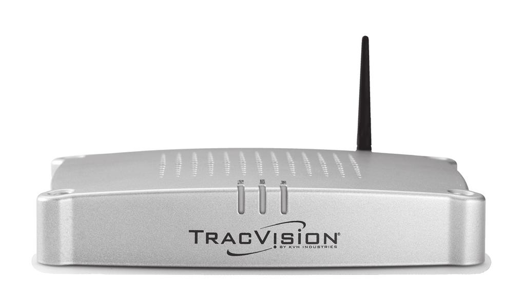
12 Introduction The TracVision system includes the following components: Antenna Housed within a protective radome, the antenna quickly acquires and tracks the desired satellite to deliver a crystal-clear television picture, even while you re on the move. Its built-in DVB-S2 technology ensures compatibility with all modern Ku-band television satellites, and its exclusive RingFire technology provides stronger signals, wider coverage, and better reception. Figure 1-2 Antenna TV-Hub The IP-enabled TV-Hub powers and controls the antenna. With its Ethernet connection and built-in Wi-Fi, you can access its easy-to-use web interface from any mobile device, allowing you to set up, operate, and monitor all aspects of the system. Its built-in library of over 100 satellites is fully customizable, and can even be updated over the Internet. Figure 1-3 TV-Hub 7

13 Introduction There are two versions of TV-Hub: TV-Hub A: Supplied with North American systems; includes a built-in DIRECTV SWM (single wire multiswitch) with its associated connectors on the rear panel; also supports DISH Network and Bell TV services TV-Hub B: Supplied with linear systems; does not include DIRECTV SWM components/connectors; identical to TV- Hub A otherwise, so it can also support DISH Network and Bell TV services Figure 1-4 TV-Hub Versions 8
14 Getting Started 2. Getting Started Contents This section explains how to turn on the system for the first time and access the web interface. Receiving Satellite TV Signals...11 Avoiding Blockage...12 Turning On the System...13 Accessing the Web Interface

15 Getting Started Receiving Satellite TV Signals Television satellites are located in fixed positions above the Earth s equator and beam TV signals down to the earth within certain regions that they serve. Therefore, to receive TV signals from a given satellite, you must be located within that satellite s unique coverage area, also known as its footprint. To view the latest TracVision satellite coverage maps, visit KVH s website at Figure 2-1 Example of a Satellite Footprint The size of the antenna makes a big difference in determining which satellites it can track and where. Larger antennas have the following advantages over smaller models: Collects more signal: As you move further away from the center of a satellite footprint, the power level, referred to as EIRP (effective isotropic radiated power), gradually fades, just like a radio station. Larger antennas can pull in more of the weak signal, so they can track a satellite at a lower EIRP than smaller antennas. Narrower beamwidth: Some satellites are very close together in the sky, separated by only a few degrees in longitude. Larger antennas receive signals within a narrower beam, reducing the chance of interference caused by transmissions from adjacent satellites. 11

16 Getting Started Avoiding Blockage Since satellites are located 22,300 miles (35,900 km) above the equator, the TracVision antenna must have a clear view of the sky to receive satellite TV signals. Anything that stands between the antenna and the satellite can block the signal, resulting in lost reception. Common causes of blockage include the following: Trees, buildings, and bridges Other rooftop equipment, such a air-conditioning units Severe weather conditions or excessive dirt on the radome can also affect reception. Figure 2-2 Example of Satellite Blockage 12
 position. The TV-Hub supplies power to the antenna. Figure 2-3 Power Switch (TV-Hub A shown) 3.")

17 Getting Started Turning On the System To turn on your TracVision system, follow these steps: 1. Make sure the antenna has a clear, unobstructed view of the sky. 2. At the rear panel of the TV-Hub, set the power switch to the On ( ) position. The TV-Hub supplies power to the antenna. Figure 2-3 Power Switch (TV-Hub A shown) 3. Wait a few minutes for system startup. Important! During startup, the TV-Hub checks the software versions installed in the antenna and updates them if necessary to match the versions it has stored for that model. All three status lights will alternate orange while this update is in progress. Do not turn off the system during this time. Updates might take up to 40 minutes. 4. Once the antenna finds the selected satellite, all three status lights on the TV-Hub should be lit green. If any lights are not lit green, refer to TV-Hub Status Indicators on page 81. Figure 2-4 Status Lights 13
18 Getting Started Accessing the Web Interface The TV-Hub s web interface allows you to check system status, switch satellites and master receiver, update software and the satellite library, and configure all aspects of the system. To access the web interface using any Wi-Fi-enabled mobile device (such as a smartphone, tablet, or laptop), follow these steps: 1. Select the TVHub-<TV-Hub serial number> network from your device s Wi-Fi settings to connect to the TV-Hub. 2. Start your web browser and enter As long as the TV-Hub is turned on and functioning properly, the Home page will appear in your browser. (If the web interface does not appear, try entering which is the default IP address of the TV-Hub.) For details on the information provided on the home page, see Status Information on the Home Page on page 79. Figure 2-5 Wireless Connection to TV-Hub Web Interface NOTE: If the TV-Hub is connected to an onboard network, you may also access the web interface over the network by entering the TV-Hub s IP address in your browser. (You can find the IP address on the Settings page of the web interface. See TV-Hub Ethernet Settings on page 19). 14
19 Network Settings 3. Network Settings Contents This section explains the various ways you can connect to the TV-Hub to access the web interface. It also explains how to connect the TV-Hub to an onboard network. Connecting the TV-Hub to Your Onboard Network...17 TV-Hub Ethernet Settings...19 Connecting to the TV-Hub Using its Built-in Wi-Fi...20 TV-Hub Wireless Settings...21 Connecting Directly to the TV-Hub Ethernet Port...22 Resetting Network Settings to Factory Defaults

20 Network Settings Connecting the TV-Hub to Your Onboard Network You can connect the TV-Hub to an onboard local area network (LAN). A network connection is necessary if either of the following conditions apply: You have one or more IP AutoSwitches installed to enable automatic satellite switching (Linear/DISH Network/Bell TV only). You want to have the ability to access the TV-Hub s web interface using any device connected to your onboard network. By default, the TV-Hub s Ethernet port is configured as a DHCP client, which means your network s router will automatically assign it an IP address. Simply connect the TV-Hub s Ethernet port to your onboard network then turn on the TV-Hub. NOTE: Use a straight-through 100 Mbps fast Ethernet UTP CAT5 cable (or better) with RJ45 connectors. Figure 3-1 TV-Hub Wired Network Connection (TV-Hub A shown) Once the TV-Hub is connected to your onboard network, you can access its web interface by entering the TV-Hub s dynamically assigned IP address in the web browser of any device connected to the network. You can find the TV-Hub s IP address on the web interface (select Settings > Network Settings). 17
21 Network Settings If Bonjour is installed on your device, you can use it to find the TV-Hub on the onboard network without knowing the IP address. Just search for its host name: TVHub-<TV-Hub serial number>. For more information about Bonjour, visit NOTE: In Dynamic (DHCP) mode, the TV-Hub could get assigned a different IP address whenever it is turned on. If you prefer, you can assign a static IP address to the TV-Hub that never changes, even after a reboot. See TV-Hub Ethernet Settings on page 19 for details. Connecting the TV-Hub to Your Onboard Network Using its Built-in Wi-Fi Although not recommended, you can modify the TV-Hub s wireless settings to connect to your onboard network using its Wi-Fi antenna, rather than using an Ethernet cable. However, once you change the TV-Hub s wireless settings from Access Point mode to Infrastructure mode, you will lose the ability to connect directly to the TV-Hub using your mobile device you will always have to connect via the network. See TV-Hub Wireless Settings on page 21 for details. 18

22 Network Settings TV-Hub Ethernet Settings By default, the Ethernet port of the TV-Hub is configured for Dynamic mode. This means that, when the TV-Hub is connected to an onboard network, the network s router assigns it an IP address. Most routers are normally configured as a DHCP (dynamic host configuration protocol) server. NOTE: On startup, if the TV-Hub does not detect a DHCP server within a few seconds, it automatically assigns itself a static IP address: If you want to assign a specific IP address to the TV-Hub, you can configure the TV-Hub for Static mode at the Settings page of the web interface (go to Settings > Network Settings). When you select Static mode, you will need to enter the desired IP address, along with its associated subnet, gateway address, and broadcast address. These settings require networking expertise. Important! If your system is set up for automatic satellite switching for DIRECTV, make sure your DIRECTV receiver(s) have IP addresses in the same subnet as the TV-Hub. If your system includes IP AutoSwitches for automatic satellite switching, make sure they are all on the same local LAN segment as the TV-Hub. Figure 3-2 Ethernet Settings 19
.")
23 Network Settings Connecting to the TV-Hub Using its Built-in Wi-Fi You can connect any Wi-Fi enabled mobile device (such as a smartphone, tablet, or laptop) to the TV-Hub via its built-in wireless access point (WAP). Figure 3-3 TV-Hub Wi-Fi Connection (TV-Hub A shown) NOTE: This direct wireless connection will not work if you changed the TV-Hub s wireless settings from Access Point mode to Infrastructure. To access the TV-Hub s web interface via Wi-Fi, follow these steps: 1. Select the TVHub-<TV-Hub serial number> network from your device s Wi-Fi settings to connect to the TV-Hub. 2. Start your web browser and enter (If the web interface does not appear, try entering which is the default IP address of the TV-Hub.) 20
.")
24 Network Settings TV-Hub Wireless Settings By default, the TV-Hub s wireless settings are configured for the following: Wireless Mode: AP (Access Point) SSID: TVHub-<TV-Hub serial number> IP address: Security Mode: Off You can change any of these settings at the Settings page of the web interface (go to Settings > Network Settings). KVH strongly advises that you select the WPA_PSK security mode and assign a unique password to prevent unauthorized access. If you keep the default settings, you re allowing anyone to access the TV-Hub with their mobile device. Important! If you select Infrastructure (IF) mode to connect the TV-Hub to your onboard network, you will no longer be able to access the TV-Hub s web interface directly you will have to go through the network. Therefore, KVH strongly recommends that you keep the TV-Hub set to Access Point (AP) wireless mode. Figure 3-4 Wireless Settings with Security Applied 21

25 Network Settings Connecting Directly to the TV-Hub Ethernet Port You can connect a computer directly to the Ethernet port on the back of the TV-Hub. This option allows you to access the TV-Hub web interface if you do not have a Wi-Fi-enabled device and you do not wish to connect the TV-Hub to an onboard network. NOTE: Use a straight-through 100 Mbps fast Ethernet UTP CAT5 cable (or better) with RJ45 connectors. Once you have connected your computer, enter into your web browser to access the TV-Hub s web interface. Figure 3-5 TV-Hub Direct Wired Connection (TV-Hub A shown) 22

26 Network Settings Resetting Network Settings to Factory Defaults If the TV-Hub s network configuration becomes corrupted such that you can no longer access the web interface, you can reset all of the network settings to their original factory settings. To reset the network settings to factory defaults, use a paper clip or pencil to press and hold the Reset button on the rear panel of the TV-Hub. Hold the button for about 5 seconds then release. The TV-Hub will reboot. Important! Resetting the system will turn off wireless security and clear your password. Be sure to reapply security settings to prevent unauthorized access. See TV-Hub Wireless Settings on page 21 for details. Figure 3-6 Reset Button (TV-Hub A shown) 23
27 Antenna Settings 4. Antenna Settings Contents This section explains how to adjust the skew of a linear LNB and modify advanced settings. Adjusting the LNB Skew Angle (Linear Only)...27 Advanced Settings
28 Antenna Settings Adjusting the LNB Skew Angle (Linear Only) Unless your antenna is equipped with automatic skew, you need to manually adjust the LNB s skew angle to optimize signal reception whenever you change your geographic location or select a different satellite. (To learn more about skew, see Understanding Skew on page 29.) To set the skew angle, follow these steps: 1. Launch the Setup Wizard from the web interface (go to Settings > General Settings). 2. Manually enter your current position at the Setup Wizard. 3. At the Setup Wizard, note the displayed skew angle for the selected satellite. 4. Turn off the TV-Hub to remove power from the TracVision antenna. CAUTION For your own safety, make sure the TracVision system is powered off before you perform any work on the antenna. 5. Remove the Phillips-head screws securing the radome to the antenna. Then carefully lift the radome straight up until clear of the antenna assembly and set it aside in a safe place. NOTE: Do not place the radome on a hot metal surface the heat may warp the radome. Figure 4-1 Radome Removal 27

29 Antenna Settings 6. Using a 2mm Allen hex key, loosen (but do not remove) the two M4 socket set screws securing the LNB to the reflector. Figure 4-2 LNB Skew Adjustment 7. Rotate the LNB clockwise or counter-clockwise until the arrow on the LNB points to the correct skew angle printed on the choke feed. NOTE: Be sure to keep the LNB fully inserted into the choke feed to ensure optimum performance. 8. Tighten the set screws to secure the LNB in place. Apply 11 in.-lbs (1.2 N-m) of torque, if possible. 9. Reinstall the radome. 28

30 Antenna Settings Understanding Skew Linearly polarized satellite signals are transmitted in vertical and horizontal waves offset exactly 90 from each other. Since these signals are oriented in a precise cross pattern, the TracVision antenna s receiving element, called the LNB, must be oriented in the same way. This orientation is referred to as the LNB s skew angle. The more precise the LNB s skew, the more signal it will collect and the better the reception. Figure 4-3 How Skew Works 29
31 Antenna Settings Advanced Settings Sleep Mode The following advanced settings enhance the performance of the TracVision antenna system: Sleep Mode (see Sleep Mode on page 30) Band/Polarization Control (see Band/Polarization Control on page 30) Sidelobe Mode (see Sidelobe Mode on page 30) Although the factory default settings work well in most cases, you can change any of them at the web interface (go to Settings > Advanced Settings). When you are moving, the antenna s motors need to run continuously to keep the antenna pointed at the satellite and locked onto the peak signal. However, if you are stationary, the motors don t need to run since the antenna s orientation to the satellite doesn t change. In these stationary conditions, Sleep mode locks the antenna in place and shuts down the motors to conserve power and silence the antenna. KVH recommends that you keep Sleep mode set to On (default setting). Band/Polarization Control Sidelobe Mode Keep Band/Polarization Control set to Master Receiver (default setting). In this mode, the satellite signal output of the TV-Hub s Receiver port is the polarization and band that is currently selected by the master receiver. The TV-Hub setting is used for linear configurations that include a multiswitch (TracVision TV5 and TV6 models only). In that mode, the TV-Hub ignores the voltage/tone from the master receiver and outputs whichever polarization/band corresponds to the voltage/ tone that is present on the coax cable connected to its Receiver port. This mode only applies to the TracVision TV6 model. 30
32 Receiver Settings 5. Receiver Settings Contents This section explains how to set up various types of satellite TV receivers to operate with the TracVision system. For receiver wiring details, refer to the Installation Guide. Configuring a Linear Receiver for Automatic Switching...33 Configuring DIRECTV Receivers for Automatic Switching...34 Allowing External Access on a DIRECTV Receiver...38 Setting the Dish Type on a DIRECTV Receiver...39 Running a Check Switch Test on a DISH Network or Bell TV Receiver...41 Activating Your Receiver(s)

33 Receiver Settings Configuring a Linear Receiver for Automatic Switching For automatic satellite switching to work properly using the DiSEqC communication protocol, you need to set up your receivers for the same satellites you installed in the TracVision antenna. Be sure to set up the satellites in the receiver in the exact same order as they were set up in the antenna. The specific setup process varies among receiver models refer to your receiver owner s manual for details. Use the table and figure below as a guide. Satellites in Antenna Slot A Slot B Slot C Slot D Matching Satellites in Receiver Port/Switch/LNB/DiSEqC 1 or A Port/Switch/LNB/DiSEqC 2 or B Port/Switch/LNB/DiSEqC 3 or C Port/Switch/LNB/DiSEqC 4 or D Figure 5-1 Linear Receiver DiSEqC Settings (Example) 33

34 Receiver Settings Configuring DIRECTV Receivers for Automatic Switching To establish communications between the TracVision system and each SWM-compatible DIRECTV receiver for automatic satellite switching, you need to set each receiver to a static IP address and enter that address, along with the receiver's location, in the TV-Hub's web interface. (For details on connecting DIRECTV receivers to the TracVision system for automatic switching, see Automatic Satellite Switching for DIRECTV on page 65.) Static IP Address Range WITHOUT an Onboard Network If the DECA Broadband Kit or the Genie DVR is connected directly to the TV-Hub's Ethernet port (no router is installed), set each receiver's IP address to any address ranging from x.2 to x.149, where x=1<the last 2 digits in the TV-Hub s serial number>. For example, if the serial number of the TV-Hub is , you might assign an IP address of Refer to the instructions in Assigning a Static IP Address to a DIRECTV Receiver on page 36. The TV-Hub has a hidden IP address of x.1 reserved for automatic switching communications. This IP address is not shown on the Network Settings page of the web interface. Figure 5-2 IP Addressing for Automatic Switching (Example) 34
35 Receiver Settings Static IP Address Range WITH an Onboard Network If the TV-Hub and the DECA Broadband Kit or Genie DVR are connected to an onboard network (i.e., router), set each receiver to a static IP address that is outside the router's DHCP range. (Refer to your router's user manual for details on finding its IP address range.) For example, if the router has an IP address of and assigns IP addresses ranging from to via DHCP, you could set each receiver's IP address to any address ranging from to Refer to the instructions in Assigning a Static IP Address to a DIRECTV Receiver on page 36. Figure 5-3 Router DHCP Settings (Example) 35
36 Receiver Settings Assigning a Static IP Address to a DIRECTV Receiver Once you have identified a valid static IP address range for your receivers, follow these steps to assign a unique static IP address within that range to each receiver. NOTE: These steps may vary, depending on your receiver's model and software version. Refer to your receiver's owner's manual for details. NOTE: A video tutorial showing how to navigate to the receiver s IP address is available in KVH s TracVision Tutorials playlist on YouTube (Internet access required). 1. Activate the receiver for DIRECTV service, if you haven t already done so (see Activating Your Receiver(s) on page 45). The receiver must be activated before you can access the required menus. 2. Press MENU on the receiver's remote control to access the onscreen menu. 3. At the main menu, highlight Settings & Help. Then select Settings. 4. Highlight and select Network Setup. 5. Select Advanced Setup. 6. Change the IP address to the new static IP address. (On a Genie DVR, the IP address is called the "Server IP"). All of the other fields can be left as is. 7. Highlight and select Connect Now to save your changes. Disregard any error messages about missing Internet connectivity. Note this receiver's IP address and location onboard for future reference. 8. Repeat this procedure for each additional receiver. Be careful not to use the same IP address twice. 36

37 Receiver Settings Figure 5-4 IP Address on a DIRECTV Receiver (Example) 37

38 Receiver Settings Allowing External Access on a DIRECTV Receiver For automatic satellite switching, the TV-Hub needs to communicate with the receiver over the network. The receiver needs to be set up to allow this external access. To allow external access on a DIRECTV receiver, follow these steps: NOTE: A video tutorial of this procedure is available in KVH s TracVision Tutorials playlist on YouTube (Internet access required). 1. Press MENU on the receiver s remote control to access the onscreen menu. 2. At the main menu, highlight Settings & Help. Then select Settings. 3. Highlight and select Whole-Home 4. Highlight and select External Device. 5. Set External Access to Allow. 6. At the warning message, select OK. Figure 5-5 External Device Settings on DIRECTV Receiver 38
39 Receiver Settings Setting the Dish Type on a DIRECTV Receiver To work with the TracVision system, the DIRECTV receiver(s) must be set to the correct dish type for your particular configuration. To set the dish type, follow these steps: NOTE: A video tutorial of this procedure is available in KVH s TracVision Tutorials playlist on YouTube (Internet access required). 1. Press MENU on the receiver s remote control to access the onscreen menu. 2. At the main menu, highlight Settings & Help. Then select Settings. 3. Highlight and select Satellite. 4. Highlight and select Repeat Satellite Setup. 5. At the warning message, press the Dash (-) button on the receiver s remote control. 6. Set the appropriate dish type for your receiver: Receiver Type Dish Type Switch Type U.S. SWM 3-LNB SWM U.S. Non-SWM and Latin America Round Multiswitch 7. Highlight and select Continue to save your changes. 39

40 Receiver Settings Figure 5-6 Satellite Dish Setup on DIRECTV Receiver 40
41 Receiver Settings Running a Check Switch Test on a DISH Network or Bell TV Receiver To operate with the TracVision system, you need to run a single Check Switch test on every DISH Network or Bell TV receiver. To run a Check Switch test, follow these steps: NOTE: A video tutorial of this procedure is available in KVH s TracVision Tutorials playlist on YouTube (Internet access required). 1. Make sure the vehicle is parked in a blockage-free area. The antenna must have an unobstructed view of the sky. Important! The antenna must remain motionless throughout this procedure. 2. Connect the receiver directly to the Receiver port on the back of the TV-Hub. You must run the Check Switch test on each receiver, one at a time, while it is connected directly to the TV-Hub via a single RF coax cable. 3. Turn on the TracVision system and connect to the web interface (see Accessing the Web Interface on page 14). Proceed through the steps of the Setup Wizard until it prompts you to run the Check Switch test. If the Setup Wizard does not display automatically, you can launch the Setup Wizard from the web interface (go to Settings > General Settings). 4. Connect a TV to the receiver so you can view the receiver s onscreen menu. NOTE: The setup process may differ depending on service provider and receiver model. Refer to your receiver owner s manual for details. 5. At the Program Remote to Receiver screen, press SAT then RECORD on the receiver s remote to begin the setup process. Important! If the Program Remote to Receiver screen does not appear, or the screen shows Acquiring Signal instead, go directly to the Point Dish screen by pressing MENU, 6, 1, 1 on the receiver s remote. Then perform steps 11 and 12 of this procedure to run a Check Switch test. In the case of the Acquiring Signal screen, you need to press MENU, 6, 1, 1 while that screen is displayed. Otherwise, you will need to reset the receiver and try again. 41

42 Receiver Settings 6. When the number for your remote control appears on the screen, select Continue. 7. Wait while the receiver downloads the latest software. This update may take up to 20 minutes. 8. At the Set Video Resolution screen, select the highest video resolution that is supported by your TV. Then run the resolution test and save your setting. 9. Allow the receiver to run two tests of its landline connections (Ethernet and phone). It probably won t detect any, since the receiver is installed in a mobile environment. 10. At the Activate Receiver screen, press STAR (*) on the receiver s remote. 11. At the Setup Details screen, select Point Dish. Then select Check Switch. The receiver now runs the Check Switch test. 12. At the Installation Summary screen, make sure all of the satellites you installed in the TracVision antenna are listed OK. Also be sure the switch type is DP34. If you do not see these results, select Test to run another test. Otherwise, select Done. Figure 5-7 Check Switch Test Results 13. At the Point Dish screen, select Done. 42
43 Receiver Settings 14. At the Setup Details screen, select Continue. 15. Allow the receiver to run two additional tests of its landline connections. 16. At this point, you may activate the receiver. Call the number provided in Activating Your Receiver(s) on page 45. Once the receiver is activated, the process is complete. 17. Repeat this procedure for any additional receivers, making sure you connect each receiver directly to the TV-Hub as directed in step 2. When you are done, reconnect all system components as necessary for your chosen configuration. 18. When you are done running Check Switch tests, proceed to the next page of the Setup Wizard. Do not close your web browser window to exit. Important! If you accidentally close your web browser window instead of proceeding to the next page of the Setup Wizard, be sure to set the Check Switch mode to Off at the General Settings page of the web interface. See Check Switch Mode on page 44 for details. 43
44 Receiver Settings Check Switch Mode When the Setup Wizard prompts you to run a Check Switch test for a DISH Network or Bell TV configuration, the antenna automatically enables Check Switch mode. In this mode, the antenna stops actively tracking and stores the relative pointing position to each installed satellite. Satellite switching is nearly instantaneous - the antenna just shifts to the stored pointing positions. This rapid switching allows a Check Switch test to pass on its first attempt. (The receiver assumes it is connected to a stationary home antenna with multiple LNBs, so it expects all satellites to be available at once.) Important! While in Check Switch mode, the antenna must remain motionless. Since the antenna is not tracking the satellite in this mode, any movement will throw off the relative pointing positions. Keep the Check Switch mode set to Off (default setting) for normal operation. Check Switch mode should only be set to On when you need to run a Check Switch test on a receiver. You can change the current Check Switch mode setting at the web interface (go to Settings > General Settings). 44
45 Receiver Settings Activating Your Receiver(s) Before you can watch television, the receiver(s) must be activated for your satellite TV service. Refer to the receiver owner s manual or packaging for details. To activate DIRECTV U.S. or DISH Network receivers, call the following: To activate: Call: DIRECTV U.S DISH Network
46 Satellite Settings 6. Satellite Settings Contents This section explains how to select, edit, and add satellites and satellite groups. Selecting a Single Satellite Creating a New Satellite Selecting a Satellite Group Creating a New Satellite Group Changing Satellites in a Group Changing Satellite Tracking Parameters
.")
47 Satellite Settings Selecting a Single Satellite If all of the programming you want to watch is carried by a single satellite, follow these steps to configure the antenna to track that one satellite: Important! KVH recommends that you run the Setup Wizard whenever you need to change the configuration of your system (especially if you need to change your satellite TV service or receiver equipment). The Wizard will guide you through all of the necessary configuration steps, including satellite selection. You can launch the Setup Wizard from the web interface (go to Settings > General Settings). 1. On the Satellites page of the web interface, set Satellite Mode to Single. 2. All satellites that are compatible with your antenna and its currently installed LNB are displayed in a list. Choose a region to filter the list for your location (e.g., Europe). You can also order the list by name, orbital slot, or region by clicking the associated header. 3. Find the desired satellite and select Installed. The antenna will start searching for the selected satellite. NOTE: If the satellite you want to track is missing, you can add it to the list. See Creating a New Satellite on page 50 for details. Figure 6-1 Single Satellite Mode 49
 information icon next to any of the User satellites. 2.")
48 Satellite Settings Creating a New Satellite If the satellite you wish to track is not included in the satellite library, you can add a new custom User satellite. To create a new satellite, follow these steps: 1. On the Satellites page of the web interface, click the (i) information icon next to any of the User satellites. 2. Fill in all of the tracking parameters with the correct information for your desired satellite. See Changing Satellite Tracking Parameters on page 56. NOTE: You can only create a satellite that is compatible with the LNB that is currently installed in the antenna. 3. Choose a friendly name for your new satellite, so that you can easily identify it later. Then save your changes. 4. To install your new satellite in the antenna for tracking, follow the steps in Selecting a Single Satellite on page 49. Figure 6-2 User Satellites (Circular) 50

49 Satellite Settings Selecting a Satellite Group The TV-Hub comes preloaded with some of the most popular groups of satellites. To select one of these preset groups for tracking, or to select a custom group that you created yourself, follow these steps: Important! KVH recommends that you run the Setup Wizard whenever you need to change the configuration of your system (especially if you need to change your satellite TV service or receiver equipment). The Wizard will guide you through all of the necessary configuration steps, including satellite selection. You can launch the Setup Wizard from the web interface (go to Settings > General Settings). 1. On the Satellites page of the web interface, set Satellite Mode to Group. Figure 6-3 Preset Satellite Groups (Example) 2. Choose a satellite group from the list. (This list will vary depending on your system s configuration.) All preset groups are listed below. 51
50 Satellite Settings Linear Groups Preset Satellite Groups (A B C D) Europe 1: Hotbird Astra1 Astra2S Astra3 Europe 2: Astra3 Astra1 Hotbird Astra2S Scandinavia: Astra4 Thor Hotbird Astra1 Compatible Antennas TV5, TV6* TV5, TV6* TV5, TV6* * Automatic skew required. DIRECTV Groups Preset Satellite Groups DIRECTV Dual: 101W 119W Tri-Am TriSat: 101W 119W 95W Tri-Am Dual: 101W 95W Compatible Antennas All TV5, TV6* TV5, TV6* * Tri-Americas LNB required (DIRECTV U.S. + Latin America). DISH Network Groups Preset Satellite Groups Eastern Arc: 61W 72W 77W Western Arc: 110W 119W 129W Legacy East Arc: 61W 110W 119W DISH 500: 110W 119W Compatible Antennas TV3, TV5, TV6* All* All All 72W: 72W only TV3, TV5, TV6* * TV1/RV1 is not compatible with the Eastern Arc or 72W at this time. In addition, due to the low elevation angle, the 129W satellite cannot be viewed by the TV1/RV1 in the Northeast U.S. Bell TV Group 52 Preset Satellite Group Bell TV Dual: 82W 91W * TV1/RV1 is limited to the 91W satellite at this time. Compatible Antennas TV3, TV5, TV6*
51 Satellite Settings Creating a New Satellite Group If there is no preset satellite group containing the satellites you want to track, you can create your own custom satellite group. Follow these steps: 1. On the Satellites page of the web interface, set Satellite Mode to Group. 2. Select Create New Group. 3. Choose up to four satellites from the satellite library to include in your new satellite group. Important! When adding linear satellites to a group, be sure to consider the skew angle for each satellite if the antenna is not equipped with automatic skew. In general, if the satellites are greater than 10 apart in longitude, you will not be able to set the LNB at a skew angle that works for all of them. You might need to adjust the skew whenever you switch satellites. 4. Choose a friendly name for your group, so that you can easily identify it later. Then save your changes. 5. To install the new satellite group in the antenna for tracking, follow the steps in Selecting a Satellite Group on page 51. NOTE: If you assign your new group the same name as an existing userdefined group, the new group will overwrite the older one. You cannot use any of the names that are reserved for preset groups. 53
52 Satellite Settings Figure 6-4 Creating a New Satellite Group 54

53 Satellite Settings Changing Satellites in a Group While you cannot alter the satellites in a preset group, you can change the satellites that are included in any user-defined group. Follow these steps to edit a user-defined group: 1. On the Satellites page of the web interface, set Satellite Mode to Group. 2. Select the group you want to modify, then select Edit Group. 3. Change any of the four satellites you want to replace. Then save your changes. Figure 6-5 Editing a Satellite Group 55
54 Satellite Settings Changing Satellite Tracking Parameters A satellite TV service provider may change a transponder frequency or other satellite parameters at any time without warning. Since the antenna uses these parameters to identify and track the satellite, the TV-Hub allows you to change the tracking parameters of any satellite in its library. NOTE: KVH regularly updates the satellite library for service provider changes. You can download the latest update from the TV-Hub web interface. See Updating the Satellite Library on page 98 for details. Your local KVH dealer or distributor will be informed whenever an update is required. NOTE: You can find satellite information on the web at (not affiliated with KVH). To manually edit the tracking parameters of a satellite, follow these steps: 1. On the Satellites page of the web interface, click the (i) information icon next to the affected satellite. 2. Make the necessary changes to the tracking parameters. Then save your changes. Be sure to set the parameters for each polarization/band. Linear satellites use four combinations of polarization/band: Horizontal Low, Horizontal High, Vertical Low, and Vertical High. Circular satellites use two polarizations in a single band: Right and Left. Editable tracking parameters for any satellite are listed below. Parameter Frequency Symbol Rate Description MHz or MHz MHz (33000 max if DVB-S2) FEC Code 1/2, 2/3, 3/4, 3/5, 4/5, 5/6, 5/11, 6/7, 7/8, 8/9, 9/9, or 9/10 56 Satellite ID Decoder Type Hexadecimal (0x####) QDSS: Legacy DSS QDC2: Digicipher II QPSK QDVB: Legacy DVB LQPSK: DVB-S2 QPSK L8PSK: DVB-S2 8PSK TQPSK: Turbo QPSK T8PSK: Turbo 8PSK


55 Satellite Settings Figure 6-6 Edit Satellite Details 3. If the satellite is a custom user-defined satellite, you can change the additional parameters listed below. Parameter Description Satellite Name User-defined name (e.g., User Sat 1) Region Orbital Slot (Longitude) Africa, Asia, Australia/New Zealand, Central/South America, Europe, or North America Longitude of the satellite s position, using the following format: xxx.xxe or xxx.xxw (leading zeros and decimal values are optional) Pre-Skew -90 to +90 Figure 6-7 Additional Parameters for User-defined Satellite NOTE: LNB type and local oscillator frequencies cannot be modified, as they are properties of the LNB installed in the antenna. 57
56 Switching Satellites 7. Switching Satellites Contents This section explains how to switch between multiple satellites installed in the antenna. Automatic Satellite Switching for Linear, DISH Network, or Bell TV...61 Automatic Satellite Switching for DIRECTV...65 Selecting Automatic Switching Mode...72 Selecting the Master Receiver...73 Manual Satellite Switching

57 Switching Satellites Automatic Satellite Switching for Linear, DISH Network, or Bell TV In Automatic satellite switching mode, the TV-Hub can accept DiSEqC satellite change commands from linear, DISH Network, or Bell TV receivers that are either: Connected directly to the TV-Hub s Receiver port Equipped with an IP AutoSwitch IP AutoSwitches send DiSEqC commands via your onboard local area network (LAN). See Network Settings on page 15 for network setup details. NOTE: An IP AutoSwitch is not required for a receiver connected directly to the TV-Hub because the TV-Hub has a built-in IP AutoSwitch. Figure 7-1 IP AutoSwitch Connections Each receiver and IP AutoSwitch needs to be set up for automatic switching, as explained in the following topics: Setting Up a Linear Receiver for Automatic Switching on page 62 Setting Up a DISH Network/Bell TV Receiver for Automatic Switching on page 63 Setting Up an IP AutoSwitch on page 64 61
58 Switching Satellites Setting Up a Linear Receiver for Automatic Switching For automatic switching to work properly with your linear receivers, be sure to set up the satellites in each receiver in the same order as they are set up in the antenna. See Configuring a Linear Receiver for Automatic Switching on page 33 for details. 62
59 Switching Satellites Setting Up a DISH Network/Bell TV Receiver for Automatic Switching For automatic switching to work properly with your DISH Network or Bell TV receivers, be sure to observe the following requirements: Make sure each receiver is DISHpro-compatible. Look for the DISH Pro logo on the box. Select a preset satellite group (see Selecting a Satellite Group on page 51). User-defined groups are limited to manual satellite switching only. Run the TracVision Setup Wizard and initiate a Check Switch test on the receiver when prompted to do so. See Running a Check Switch Test on a DISH Network or Bell TV Receiver on page 41 for details. You can launch the Setup Wizard from the web interface (go to Settings > General Settings). NOTE: In some cases, a DISH Network receiver might automatically switch from a high-definition (HD) channel to its standard-definition (SD) equivalent. To prevent this from happening, always tune to the HD-only channels at the upper range of the channel list (above 1000), or set up the receiver to block the SD channels (from the Main Menu, select Locks:5 > Channel Locks:2). 63
. You can find the serial number on the bottom of the IP AutoSwitch.")
60 Switching Satellites Setting Up an IP AutoSwitch Whenever you install a new IP AutoSwitch, you need to add it to the Autoswitch page of the web interface. Enter the IP AutoSwitch s serial number and assign it a friendly name (e.g., Master Bedroom ). You can find the serial number on the bottom of the IP AutoSwitch. Figure 7-2 Adding an IP AutoSwitch to the Autoswitch Page 64
61 Switching Satellites Automatic Satellite Switching for DIRECTV In Automatic satellite switching mode, the TV-Hub can accept commands from the master SWM-compatible DIRECTV receiver to automatically switch between the 101W and 119W satellites. (To learn more about SWM technology, see Understanding DIRECTV SWM Technology on page 71.) The TV-Hub communicates with the master receiver via the TV-Hub s Ethernet port link to your DIRECTV coax network. Set up this communication link with your SWM-compatible receivers, as explained in the following topics: DIRECTV Coax Network Connections on page 66 Additional Equipment for Old DIRECTV Receivers on page 68 Setting Up a DIRECTV Receiver for Automatic Switching on page 69 NOTE: The 119W satellite only carries local channels for certain regions of the country. (You can find a list of these regions in the Setup Wizard.) If your locals are carried on DIRECTV s main 101W satellite, you do not need to switch satellites. 65
62 Switching Satellites DIRECTV Coax Network Connections DIRECTV recently adopted coax networking technology, by which both satellite TV signals and network communications data are carried by the coax cables. This simplifies installation, since Ethernet cables don't need to be run to all of the receivers. Non-Genie Configurations If a Genie DVR (HR44 or HR34) is not present on your DIRECTV SWM network, you need to install a DECA with power supply and DC to RF adapter, collectively referred to as a DECA Broadband Kit (KVH part no ) and formerly called a Cinema Connection Kit. When connected to the SWM splitter and the TV-Hub's Ethernet port, either directly or via an onboard router, the DECA relays messages between the DIRECTV coax network and the Ethernet network. Figure 7-3 Non-Genie Configuration 66
63 Switching Satellites Genie Configurations Full DECA Broadband functionality is built into Genie DVRs (HR44 or HR34). So if a Genie DVR is present on your DIRECTV SWM network, no external DECA Broadband kit is required. Just connect the Genie's Ethernet port to the TV-Hub's Ethernet port, either directly or via an onboard router. The Genie DVR provides the link between the DIRECTV coax network and the Ethernet network. NOTE: If you cannot easily connect the Genie DVR s Ethernet port to the TV-Hub or an onboard network, you can use a DECA Broadband Kit, as explained in Non-Genie Configurations on page 66. NOTE: Genie clients cannot switch satellites; they can only view programming carried by the satellite that is currently selected. Figure 7-4 Genie Configuration 67
, KVH part no. 19-0860 H20* Band Stop Filter, KVH part no.")
64 Switching Satellites Additional Equipment for Old DIRECTV Receivers In addition to the DECA Broadband Kit or a Genie DVR, you might need to connect an additional device to individual receiver(s), depending on the model. Old Receiver Models H21, H22, H23, HR21, HR22, HR23 Additional Device Required DECA (included in DECA Broadband Kit), KVH part no H20* Band Stop Filter, KVH part no *Model HR requires additional devices. Contact KVH Technical Support for details. Connect these additional device(s) in-line between the receivers and the SWM splitter. Figure 7-5 Additional Equipment for Older Receivers H21, H22, H23, HR21, HR22, and HR23 Models These receivers do not have built-in DECA functionality, but they have an Ethernet port for network connectivity. An additional DECA (KVH part no ) is required for each of these receivers to support coax networking, supplying the satellite TV signal to the receiver's "Satellite In" port and network communications data to its Ethernet port. (If there are two of each port, use the "Satellite In 1" and "Ethernet 1" ports.) 68 NOTE: Each DECA that you connect directly to a receiver is powered by the receiver. They do not require the separate power supply included in the DECA Broadband Kit.
65 Switching Satellites H20 Model This receiver is not network-ready. It is only designed to receive a satellite TV signal via its "Satellite In" port. Since both the satellite TV signal and network communications data are present on the coax cables, a band stop filter (KVH part no ) is required to block the network data to prevent potential damage to the receiver. Since the H20 cannot communicate over the network, it cannot control satellite selection. Important! Be sure to connect all band stop filters before connecting the coax cables. Setting Up a DIRECTV Receiver for Automatic Switching During system installation, your SWM-compatible receivers should have been set up for you. (See the Installation Guide for details.) If you wish to add a new SWM-compatible receiver, follow these steps: 1. Set the receiver s Dish Type to 3-LNB and Switch Type to SWM. See Setting the Dish Type on a DIRECTV Receiver on page 39 for details. 2. Set up the receiver to allow external device access. See Allowing External Access on a DIRECTV Receiver on page 38 for details. 3. Assign a unique static IP address to the new receiver. See Configuring DIRECTV Receivers for Automatic Switching on page 34 for details. 4. Add the new receiver to the Autoswitch page of the web interface. Enter the receiver s static IP address and assign it a friendly name (e.g., Master Bedroom ). NOTE: If the TV-Hub is unable to communicate with the receiver, try resetting the receiver (press its red reset button or unplug it, wait 15 seconds, then plug it back in and turn it on). 69

66 Switching Satellites Figure 7-6 Adding a DIRECTV Receiver to the Autoswitch Page 70

67 Switching Satellites Understanding DIRECTV SWM Technology The TV-Hub has a built-in DIRECTV single wire multiswitch (SWM), allowing you to connect multiple SWM-compatible receivers via a single coax cable. At startup, the SWM allocates one of eight channels to each tuner it detects on the cable. Recording devices will consume more than one channel, as they offer the ability to record on one or more channels while watching another. Device Tuners SWM Receiver 1 SWM DVR 2 Genie 5 Genie Client 0 Figure 7-7 DIRECTV SWM Technology 71

68 Switching Satellites Selecting Automatic Switching Mode To select automatic switching, simply select the Automatic satellite switching mode at the Home page of the web interface. Figure 7-8 Automatic Satellite Switching on Home Page 72


69 Switching Satellites Selecting the Master Receiver The master receiver controls satellite selection. The TracVision antenna will switch between satellites automatically as you change channels using the master receiver s remote control. All other receivers will only be able to select channels that are carried by the currently selected satellite. NOTE: The system must first be set to Automatic satellite switching mode before you can select a master receiver. See Selecting Automatic Switching Mode on page 72. To make a different receiver the master, simply select it on the Home page of the web interface. Figure 7-9 Master Receiver Selection As an alternative, if the receiver is connected to an IP AutoSwitch, you can press the Master Select button on the IP AutoSwitch to make its associated receiver the master. Figure 7-10 IP AutoSwitch Master Select Button 73

70 Switching Satellites Manual Satellite Switching Even if your system is set up for automatic satellite switching, you always have the option to manually switch satellites at the Home page of the web interface. Simply select the Manual satellite switching mode then select the desired satellite from the displayed list of installed satellites. Important! When you select Manual switching mode, the system no longer responds to receiver satellite change commands. To restore automatic switching, you need to select the Automatic satellite switching mode at the Home page. Figure 7-11 Manual Satellite Selection on Home Page 74
71 Troubleshooting 8. Troubleshooting Contents This section identifies some basic problems along with their possible causes and solutions. It also explains what the status lights and error messages indicate, how to view the system logs and information, and how to get technical support. Basic Checks...77 Status Information on the Home Page...79 TV-Hub Status Indicators...81 IP AutoSwitch Status Indicator...84 Error Messages...85 System Logs...88 System Information...91 Technical Support
72 Troubleshooting Basic Checks If you are experiencing a problem receiving satellite TV with your TracVision system, first check the following: Check the System Status Information Check the status indicators in the upper-left corner of the Home page of the web interface, or check the three lights on the front of the TV-Hub itself. All three should be lit solid green. See TV-Hub Status Indicators on page 81 for details. Also look for an error message on the Home page (see Error Messages on page 85). Check for Satellite Signal Blockage If the antenna is continuously searching for the satellite, check the area around the antenna for blockage. The antenna needs an unobstructed view of the sky to receive satellite signals. See Avoiding Blockage on page 12 for details. Excessive dirt on the radome and severe weather can also affect reception. If there is no blockage, you might be located outside the coverage area of the selected satellite. Visit for details. Make Sure Your Receivers Are Set Up Properly Your satellite TV receivers might need to be configured for the desired satellite(s) and/or operating mode. Refer to Receiver Settings on page 31 for details. Check Power and Cables Make sure power is applied to all system components. Also make sure all cables are connected tightly. Refer to the Installation Guide for wiring details. Make Sure the Software and Satellite Library Are Up-to-Date To update the system to the latest software version, refer to Updating the Software on page 100. To update the satellite library, refer to Updating the Satellite Library on page 98. Adjust the LNB Skew Angle (Linear Systems Only) If your antenna is not equipped with automatic skew, you need to manually set the antenna s LNB to the correct skew angle for the selected satellite and your current location. Refer to Adjusting the LNB Skew Angle (Linear Only) on page 27 for details. 77
73 Troubleshooting Restart the System Try restarting the system at the web interface (see Restarting the System on page 103). If you cannot access the web interface, turn off the TV-Hub at the rear panel power switch, then turn it back on. 78
 Current satellite switching mode:")
74 Troubleshooting Status Information on the Home Page The Home page of the web interface provides basic system status information, as described below. Figure 8-1 Home Page Item A B C D E Description Three status indicators match the physical status lights on the TV-Hub (see TV-Hub Status Indicators on page 81) Current satellite switching mode: Automatic or Manual Currently selected satellite, satellite signal strength, and general status of the antenna: Tracking Searching Initializing Boot Idle Error Currently selected master receiver (only shown in Automatic satellite switching mode) Antenna model 79
75 Troubleshooting Item F G H Description Latitude/longitude you entered in the Setup Wizard, if applicable List of satellites currently installed in the antenna Tracking status visual display; a green line between the antenna and the satellite indicates the antenna is tracking the satellite 80

76 Troubleshooting TV-Hub Status Indicators Status lights on the Home page of the web interface and on the front of the TV-Hub itself indicate the current status of the system and can help you identify problems quickly. Figure 8-2 TV-Hub Status Lights During normal operation, all three lights should be lit green. The following tables explain what the different light conditions indicate. If an error condition exists, view the error message on the Home page of the web interface (see Error Messages on page 85). Important! All three status lights will alternate orange whenever a software update is in progress. Updates might take up to 40 minutes. Do not turn off the system during this time. NOTE: During startup, each status light will illuminate orange for a few seconds. 81
77 Troubleshooting TV-Hub Light The table below explains what the TV-Hub light indicates. State Off Green Green, Flashing Orange, Flashing Description TV-Hub is powered off, or there is no power input TV-Hub is operating normally TV-Hub is initializing TV-Hub is operational, but a minor error exists that you might be able to fix Red TV-Hub is not operational; a major error exists contact KVH Technical Support Red, Flashing TV-Hub is not operational; a major error exists that you might be able to fix Antenna Light The table below explains what the Antenna light indicates. State Off Green Green, flashing Orange Orange, flashing Red Red, Flashing Description No power input to the antenna Antenna is tracking a satellite Antenna is initializing or searching for a satellite Antenna has been halted by a technician Antenna is operational, but a minor error exists that you might be able to fix Antenna is not operational; a major error exists contact KVH Technical Support Antenna is not operational; a major error exists that you might be able to fix 82
78 Troubleshooting Power Light The table below explains what the Power light indicates. State Off Green Red, Flashing Description TV-Hub is powered off, or there is no power input Good input power Input power is unacceptable; a major error exists that you might be able to fix 83
79 Troubleshooting IP AutoSwitch Status Indicator A status light on the IP AutoSwitch indicates the current status of the IP AutoSwitch. Figure 8-3 IP AutoSwitch Status Light The table below explains what the IP AutoSwitch status light indicates. State Off Green Orange Orange, Flashing Red Description No power input from the receiver Registered with the TV-Hub and currently selected as the master Registered with the TV-Hub but not currently selected as the master Initializing Detected one of the following errors: Unable to communicate with the TV-Hub Network is not detected Unable to register with the TV-Hub 84

80 Troubleshooting Error Messages If any of the Status indicators on the Home page of the web interface are flashing orange, flashing red, or solid red, click on it to view the error message. Figure 8-4 Example of Error Messages under Status Indicators The table below lists all of the possible error messages. Many of these faults should only be repaired by a KVH-certified technician; contact KVH Technical Support for assistance (see Technical Support on page 93). Error Description 100 There is an open circuit in the DC power wires running between the antenna and the TV-Hub. The TV-Hub detects no DC current feed to the antenna. Check the RF1 cable between the antenna and the TV-Hub. 101 There is a short circuit in the DC power wires running between the antenna and the TV-Hub. The TV-Hub detects an overload condition. Check the RF1 cable between the antenna and the TV-Hub. 102 The TV-Hub is not providing the proper DC voltage to the antenna (should be VDC). Contact KVH. 104 The software update file you selected is corrupt. Try a new update file. 105 The TV-Hub is unable to read from or write to its EEPROM. Contact KVH. 106 The TV-Hub has lost communications with the antenna. Check the RF1 cable between the antenna and the TV-Hub. 85
81 Troubleshooting Error Description 107 The TV-Hub internal temperature exceeds acceptable limits. If the problem persists, you might need to relocate the unit to an area that provides better ventilation. 108 An automated reboot of the TV-Hub is in process to resolve low memory. No action is required. 109 The TV-Hub is running low on memory but it should be able to recover without a reboot. 111 The TV-Hub is unable to initialize its built-in wireless access point (WAP). Contact KVH. 119 The 24 VDC power to the internal SWM module is out of range. DIRECTV outputs are disabled. Contact KVH. 124 The software update file you selected is not valid for your antenna model. Try a new update file. 128 The software update failed. Retry updating the software. If it fails again, check the RF1 cable between the antenna and the TV-Hub. 129 One of the TV-Hub s power supplies is out of range. Contact KVH. 130 The TV-Hub DC input voltage is out of range (should be VDC). Check the power source that is supplying DC power to the TV-Hub. 131 The TV-Hub detects no DC current feed to the antenna, following a period of normal operation. Check the RF1 cable between the antenna and the TV-Hub. 200 The antenna is not receiving adequate DC power from the TV-Hub. Check the RF1 cable between the antenna and the TV-Hub. 203 The antenna s main board has lost communications with the azimuth and elevation motors. Contact KVH. 204 The antenna s main board has lost RF communications. Contact KVH. 205 The antenna s azimuth motor has a power failure. Contact KVH. 206 The antenna s azimuth motor or limit switch failed. Contact KVH. 86
82 Troubleshooting Error Description 207 The antenna s elevation motor has a power failure. Contact KVH. 208 The antenna s elevation motor or limit switch failed. Contact KVH. 222 The antenna s internal temperature exceeds acceptable limits. Turn off the system and allow it to cool. 223 The antenna s main board has lost gyro calibration data. A technician should calibrate the antenna s gyros. 226 The antenna has lost RF communications. Contact KVH. 227 The antenna s RF software might be corrupted. Contact KVH. 228 The antenna has lost RF communications. Contact KVH. 229 The antenna s RF software might be corrupted. Contact KVH. 231 The antenna s RF software might be corrupted. Contact KVH. 232 The antenna s RF software might be corrupted. Contact KVH. 241 The antenna s main board detects a power failure. Contact KVH. 269 The main antenna processor detects that LNB voltage is out of range. Contact KVH. 270 The azimuth or elevation gyro needs to be replaced. Contact KVH. 272 The antenna s main software does not match the antenna type. Contact KVH. 273 The antenna s motor software does not match the antenna type. Contact KVH. 275 The azimuth or elevation gyro needs to be replaced. Contact KVH. 276 The antenna s main board has lost accelerometer calibration data. A technician should calibrate the antenna s accelerometer. 87
83 Troubleshooting System Logs Two system logs are available on the Support page of the web interface to capture historical system data: Operational Log (see Operational Log on page 89) Event Log (see Event Log on page 90) 88

84 Troubleshooting Operational Log The Operational Log, when initiated, records all messages that the antenna system generates within a period of several minutes. To start a new log or view the current log, select Operational Log on the Support page of the web interface. Then select the desired option: View Current Log: This option simply opens the current Operational Log. You can save this log as a text file (filename: IPACU.serial.log) and send it to a technician or KVH Technical Support. Start New Log: This option deletes the current Operational Log and begins recording a new one. Restart System & Start New Log: This option deletes the current Operational Log, restarts the antenna, and begins recording a new Operational Log. This log will include the system s startup messages, which include the results of various self-test routines. When you start a new log, the progress bar increments until the log file reaches the maximum allowed file size (100 KB). This normally captures about 20 minutes of data. Figure 8-5 Operational Log Options 89
 to your computer and e-mail it to KVH Technical Support.")
85 Troubleshooting Event Log The Event Log keeps a historical record of all major system events, including any error messages the antenna system generates. On the Support page of the web interface, select Event Log. You can then save the log file (filename: majorerror.log) to your computer and it to KVH Technical Support. Figure 8-6 Event Log 90
. You will need this information whenever you contact KVH Technical Support. It is very useful for diagnostics.")
86 Troubleshooting System Information You can find the serial numbers, software versions, voltages, and other technical information for the TV-Hub and antenna on the Support page of the web interface (go to Support > System Info). You will need this information whenever you contact KVH Technical Support. It is very useful for diagnostics. Figure 8-7 System Info: TV-Hub 91

87 Troubleshooting Figure 8-8 System Info: Antenna Unit 92

88 Troubleshooting Technical Support The TracVision system is a sophisticated electronic device; only specially trained KVH-certified technicians have the tools and expertise necessary to diagnose and repair a system fault. Therefore, if you experience an operating problem or require technical assistance, please contact KVH Technical Support: North/South America, Australasia: Phone: support@kvh.com Europe, Middle East, Africa, Asia-Pacific: Phone: support@emea.kvh.com Please have your system serial numbers and software versions handy before you call (see System Information on page 91). Remote Diagnostics If your TV-Hub is connected to the Internet via an onboard network, KVH Technical Support might be able to troubleshoot your system remotely over the Internet. Important! KVH Technical Support will guide you through the process of enabling remote diagnostics on the TV-Hub. Enable this connection only when requested by KVH Technical Support. Figure 8-9 Remote Access 93
89 Maintenance 9. Maintenance Contents This section explains how to perform preventive maintenance to keep the system in tip-top shape. It also explains how to update the software and satellite library, and restart system components. Preventive Maintenance...97 Updating the Satellite Library...98 Updating the Software Corrective Maintenance Restarting the System

90 Maintenance Preventive Maintenance The following tasks should be performed periodically to help maintain peak performance: Vacuum the vents on the TV-Hub. Air needs to flow through these vents to cool the electronic components and prevent overheating. Figure 9-1 Vents on TV-Hub Clean the outside of the antenna with fresh water to remove grime. Dirt buildup can affect reception of satellite signals. You may use mild detergent, but avoid abrasive cleansers and high-pressure water. Inspect the cable connections at the TV-Hub for any wear and tear. Repair any damaged cables. Ensure the system is running the latest software version. See Updating the Software on page 100 for details. Also make sure the TV-Hub s satellite library is up to date. See Updating the Satellite Library on page 98 for details. 97
91 Maintenance Updating the Satellite Library Service providers occasionally change the tracking parameters of their satellites, necessitating an update to the data in the TracVision satellite library. You can update your system s satellite library to the latest version at any time by downloading the file from KVH s Update server and uploading it to the TV-Hub. When you update the library, the new version simply overwrites the previously installed version. Important! With the exception of user-defined satellites, updating the satellite library overwrites any changes you have made to the satellites tracking parameters. All parameters for preset satellites revert to their factory default settings. Use one of the following methods to update the satellite library: Using an Onboard Network with Internet Access If the TV-Hub is connected to an onboard network that has an Internet connection, you can use that connection to download the library file. Follow these steps: 1. Connect your computer to the same network as the TV-Hub. 2. At the Updates page of the web interface, select the satellite library. Then select Download Update. This will download the latest version of the library file onto your computer. 3. Select Install Update. Then navigate to and select the library file (it has a.xml extension) saved on your computer. It will only take a few seconds for the update to complete. Using a Smartphone or Tablet If you have an Apple ios or Google Android smartphone or tablet, and your device has an Internet connection, you can use the TracVision TV/RV App to download the latest library file and upload it to the system. You can download the App for free from the Apple itunes App Store or Google Play Store. Using a Computer with Internet Access If your computer has an Internet connection, you can use that connection to download the library file. Follow these steps: 98
. 3.")
92 Maintenance 1. Download the latest version of the library file onto your computer from the KVH website (go to Support/Product-Support-Library/Software-Updates). 2. Once you have downloaded the file onto your computer, use the same computer to access the TV-Hub s web interface (see Accessing the Web Interface on page 14). 3. At the Updates page of the web interface, select the satellite library then select Install Update. Navigate to and select the library file (it has a.xml extension) saved on your computer. It will only take a few seconds for the update to complete Figure 9-2 Satellite Library Update 99
93 Maintenance Updating the Software KVH periodically releases new versions of software to enhance the performance and capabilities of the system. You can update your system to this latest software at any time by downloading the file from KVH s web server and uploading it to the system. When you update the software, the new version simply overwrites the previously installed version. A single software package includes updates to all components in the antenna and TV-Hub. Use one of the following methods to update the software: Using an Onboard Network with Internet Access If the TV-Hub is connected to an onboard network that has an Internet connection, you can use that connection to download the software. Follow these steps: 1. Connect your computer to the same network as the TV-Hub. 2. At the Updates page of the web interface, select the antenna. Then select Download Update. This will download the latest version of the software onto your computer via the onboard network s Internet connection. 3. Select Install Update. Then navigate to and select the update file (it has a.kvh extension) saved on your computer. 4. Wait for the update to complete. It may take up to 45 minutes. Using a Smartphone or Tablet If you have an Apple ios or Google Android smartphone or tablet, and your device has an Internet connection, you can use the TracVision TV/RV App to download the latest software and upload it to the system. You can download the App for free from the Apple itunes App Store or Google Play Store. Using a Computer with Internet Access If your computer has an Internet connection, you can use that connection to download the software. Follow these steps: 1. Download the latest version of software onto your computer from the KVH website (go to Product-Support-Library/Software-Updates). 100
 saved on your computer. 4.")
94 Maintenance 2. Once you have downloaded the file to your computer, use the same computer to access the TV-Hub s web interface (see Accessing the Web Interface on page 14). 3. At the Updates page of the web interface, select the antenna then select Install Update. Navigate to and select the update file (it has a.kvh extension) saved on your computer. 4. Wait for the update to complete. It may take up to 45 minutes. NOTE: The TV-Hub s status lights will alternate orange while the update is in progress. Figure 9-3 Antenna Software Update (TV5 shown) 101
95 Maintenance Corrective Maintenance If a system component fails, it will need to be replaced by a KVHcertified technician. Instructions are provided with the replacement part. Important! Field replaceable units should only be replaced by a trained, KVHcertified technician. To find a technician near you, visit or contact KVH Technical Support (see Technical Support on page 93). 102
. Restart Antenna: Restarts the TracVision antenna.")
96 Maintenance Restarting the System If you experience a problem with the system, you may need to restart the hardware. You can restart the following system components at the web interface (go to Support > Restart System). Restart Antenna: Restarts the TracVision antenna. Choose this option whenever the antenna is unable to find the satellite. Restart All: Restarts both the TV-Hub and the antenna. Choose this option if the problem cannot be isolated to the antenna. Figure 9-4 Restart System Menu 103
TracVision 95W LNB Installation
 TracVision 95W LNB Installation To enable a TracVision system to receive DIRECTV international programming from the linear satellite located at 95W, a 95W LNB must be installed in a secondary M7SK or M9
TracVision M9 LNB Replacement Instructions
 TracVision M9 LNB Replacement Instructions These instructions explain how to replace an LNB with a new LNB of the same type in a TracVision M9. Installation Steps LNB Replacement Instructions 1. Remove
TracVision M5/M7 Control Panel Configuration. TracVision M5/M7 User s Guide
 TracVision M5/M7 Control Panel Configuration TracVision M5/M7 User s Guide TracVision M7 with Auto Skew Important Information About Your System Important Information About Your TracVision M7 System with
LNB Conversion Instructions for TracVision C3/R5/R4
 LNB Conversion Instructions for TracVision C3/R5/R4 These instructions explain how to change between a circular (North American-type) LNB and a linear (European-type) LNB in a TracVision C3/R5/R4 system.
TracVision M5/M7. Configuration. GyroTrac. User s Guide
 TracVision M5/M7 GyroTrac Configuration User s Guide TracVision M5/M7 RF7 Board Addendum PLEASE READ! Important Addendum to the Product Manuals Your TracVision M5/M7 antenna is equipped with a new RF7
KVH Tri-Sat AutoSwitch Kit Installation and Operation Instructions for TracVision M3DX
 KVH Tri-Sat AutoSwitch Kit Installation and Operation Instructions for TracVision M3DX A The following instructions explain how to install and operate the Tri-Sat AutoSwitch Kit on a TracVision M3DX system.
TracVision R6DX Installation Guide
 TracVision R6DX Installation Guide TracVision R6DX Installation Guide KVH s Premier Satellite TV System for RVs These instructions explain how to install the TracVision R6DX on an RV or motor coach. Complete
TracVision R6DX Installation Guide
 TracVision R6DX Installation Guide These instructions explain how to install the TracVision R6DX satellite TV antenna system on an RV or motor coach. Complete instructions on how to use the system are
IMPORTANT! Special Instructions for the TracVision M3DX Conversion System ( )
") IMPORTANT! Special Instructions for the TracVision M3DX Conversion System (01-0279-05) You have purchased a special TracVision M3DX conversion system that can be configured for either circular or linear
IMPORTANT! Special Instructions for the TracVision M3DX Conversion System (01-0279-05) You have purchased a special TracVision M3DX conversion system that can be configured for either circular or linear
TracVision M5/M7 User s Guide
 TracVision M5/M7 GyroTrac Configuration TracVision M5/M7 User s Guide TracVision M7 with Auto Skew Important Information About Your System Important Information About Your TracVision M7 System with Auto
TracVision M3 DX Version. Circular Configuration. TracVision M3 User s Guide
 TracVision M3 DX Version Circular Configuration TracVision M3 User s Guide TracVision M3DX Circular Configuration User s Guide This user s guide provides all of the basic information you need to operate,
TracVision. with Multi-service Interface Box/Controller. TracVision M1DX User s Guide
 TracVision M1DX with Multi-service Interface Box/Controller TracVision M1DX User s Guide TracVision M1DX Multi-service Interface Box/ Controller Configuration User s Guide This user s guide provides all
TracVision R1DX. with Multi-service Interface Box/Controller. TracVision R1DX Installation Guide
 TracVision R1DX with Multi-service Interface Box/Controller TracVision R1DX Installation Guide TracVision R1DX Installation Guide Multi-service Interface Box/Controller Configuration These instructions
TracVision M5/M7 Switchplate Configuration. TracVision M5/M7 User s Guide
 TracVision M5/M7 Switchplate Configuration TracVision M5/M7 User s Guide TracVision M5/M7 Switchplate Configuration User s Guide This user s guide provides all of the basic information you need to operate,
Single cable multiswich programmer PC102W
 Single cable multiswich programmer PC102W 1. Product description The PC102W - single cable multiswich programmer (in the text - programmer) is useful instrument while configuring and troubleshooting SAT
TracVision TV1 & TV3. Ultra-compact systems for bringing the best satellite TV entertainment onboard
 TracVision TV1 & TV3 Ultra-compact systems for bringing the best satellite TV entertainment onboard TV-Hub user interface gives you control at your fingertips on any mobile device or computer. TracVision
RF Mogul. Quick Start. Model: SDC1. Satellite Dish Controller
 RF Mogul Satellite Dish Controller Model: SDC1 Quick Start 29 February 2012 Minimum required hardware to find a Satellite! This Quick Start document is for connecting and operating a General Dynamics C125M
TracVision R6 & Multi-service Interface Box. User s Guide
 TracVision R6 & Multi-service Interface Box User s Guide Welcome to TracVision R6 TracVision User s Guide R6 Satellite TV Antenna & Interface Box This manual provides detailed instructions on the proper
TracVision HD7. Installation Guide
 TracVision HD7 Installation Guide TracVision HD7 Installation Guide These instructions explain how to install the TracVision HD7 satellite TV antenna system on a vessel. Complete instructions on how to
TracVision Interface Box Circular Configuration for North America. TracVision Interface Box User s Guide
 TracVision Interface Box Circular Configuration for North America TracVision Interface Box User s Guide TracVision Interface Box Circular Configuration for North America User s Guide This user s guide
Specifications. Compatible Receivers. Compatible Satellites. DIRECTV Sat DISH Sat DIRECTV Receiver Compatibility
 Quick Setup Make sure the Carryout G2 antenna is in a location with a clear view of the southern sky. Connect the provided coaxial cable from the primary receiver to the MAIN port on the base. Connect
OSD. EXECUTIVE / MiniDome USERS MANUAL. USING THE MOTOSAT DISH POINTING SYSTEM EXECUTIVE / MiniDome OSD
 EXECUTIVE / MiniDome OSD USERS MANUAL USING THE MOTOSAT DISH POINTING SYSTEM EXECUTIVE / MiniDome OSD MotoSAT Corporation Created April 22, 2003 1-800-247-7486 CONGRATULATIONS! on your purchase of your
Interactive Satellite Terminal Installation / Validation Manual
 Installation / Validation Manual Version October 5, 2016 Index INTERACTIVE SATELLITE TERMINAL 1. FCC COMPLIANCE... 3 2. TECHNICAL FEATURES...4 3. GENERAL DESCRIPTION...5 4. ELEMENTS CONTAINED IN THE TERMINAL...6
DataSAT ACU-2 Controller Wiring Configuration - Operation
 DataSAT ACU-2 Controller Wiring Configuration - Operation This manual covers basic wiring, antenna controller configurations, and typical operation. For proper operation, wiring and configuration are very
TracVision HD7. Installation Guide
 TracVision HD7 Installation Guide TracVision HD7 Installation Guide These instructions explain how to install the TracVision HD7 satellite TV antenna system on a vessel. Complete instructions on how to
Welcome! Troubleshooting. Can the antenna see the satellite? Turning On the System. Single-Receiver Setup. Product Serial Number
 RC32 FORMAT PWR & TV POWER ON GUIDE OFF ACTIVE R LIST BACK EXIT MENU VOL INFO CHAN PAGE PREV 0 ENTER Welcome! Basic Operation ing Satellites Troubleshooting Congratulations! You have purchased the most
Dealer Training Test. Winegard Dealer Training
 Dealer Training Test Winegard Dealer Training Test 105 General Information 1. Most RV wiring uses two types of coax cable, RG-59 and RG-6. Which type of coax cable should be used for satellite applications?
Subject: DISH Network s Reconfiguration of the 129 W Satellite
 Technical Bulletin Date: December 4, 2009 Subject: DISH Network s Reconfiguration of the 129 W Satellite Products Affected TracVision R4SL, R5SL TracVision R4, R5, L3, and S3 systems that have been upgraded
Fully ly Automaticti. Motorised Satellite t TV System. User s manual REV
 REV. 1.0 Fully ly Automaticti Motorised Satellite t TV System User s manual Customer Help Line: 1300 139 255 Support Email: support@satkingpromax.com.au Website: www.satkingpromax.com.au www.satkingpromax.com.au
Portable In-Motion Automatic Satellite System. Model VQ3000
 Portable In-Motion Automatic Satellite System with built-in DVB for positive satellite identification Model VQ3000 Operating Instructions Satellite Solutions for Mobile Markets 11200 Hampshire Avenue South,
Interactive Satellite Terminal Installation / Validation Manual
 Installation / Validation Manual Version September 14, 2017 Index INTERACTIVE SATELLITE TERMINAL 1. FCC COMPLIANCE... 3 2. TECHNICAL FEATURES...4 3. GENERAL DESCRIPTION...5 4. ELEMENTS CONTAINED IN THE
EAGLE RE-1 CONTROLLER For Use On MotoSAT HD Mounts
 EAGLE RE-1 CONTROLLER For Use On MotoSAT HD Mounts Supported Systems HD SL5 DirecTV HD DP3 Dish Network HD SC2 SHAW HD DP3 BELL TV EXECUTIVE DirecTV 101 Dish Network 119 MSC-60 SHAW MD-500 Dish Network
Portable Automatic Satellite System. Model VQ2000
 Portable Automatic Satellite System with built-in DVB for positive satellite identification Model VQ2000 Operating Instructions Satellite Solutions for Mobile Markets 11200 Hampshire Avenue South, Bloomington,
USER MANUEL. SNIPE 2 Ref R13
 USER MANUEL SNIPE 2 Ref. 0141317R13 Contents 1. General Information 1-1. Introduction 1-2. Proper use and operation 1-3. Safety notes......... 2 3 3 2. Contents 2-1. Accessory included 2-2. Name of parts......
EAGLE RE-1 CONTROLLER
 EAGLE RE-1 CONTROLLER For Use On ALL MotoSAT Mounts Supported Systems HD SL5 DirecTV HD DP3 Dish Network HD SC2 SHAW HD DP3 BELL TV EXECUTIVE 18" DirecTV 101 Dish Network 119 MSC-60 SHAW MD-500 Dish Network
RF Mogul. Operation Manual. MotoSAT J1/D4 Controllers. Firmware Upgrade for
 RF Mogul Firmware Upgrade for MotoSAT J1/D4 Controllers Operation Manual Version 14.01 13 April 2014 Index SDC1 Satellite Dish Controller Features 1 Getting Started 2 Quick Setup 2 Front Panel Operation
Field Service Procedure Replacement PCU Kit, ST24
 1. Brief Summary: Troubleshooting document for diagnosing a fault with and replacing the main PCU PCB on the ST24 antenna. 2. Checklist: Verify Initialization Built In Test 3. Theory of Operation: The
TracVision M1 Installation Guide. TracVision
 TracVision M1 with Multi-service Interface Box/Controller (Model M1dx DISH Network Configuration) (Model M1-C ExpressVu Configuration) Models M1d x / M1-C TracVision M1 Installation Guide TracVision M1
UMN_ User Manual Antenna Simplex. TECHNO-MEDIA srl Via IV Novembre 92, Bollate (MB) tel
 tel") UMN_00094400 User Manual Antenna Simplex TECHNO-MEDIA srl Via IV Novembre 92, 20021 Bollate (MB) tel. 0248672988 - info@techno-media.it Aggiornamenti Revision N Date Owner Notes 1 02/03/2017 T-Media First
UMN_00094400 User Manual Antenna Simplex TECHNO-MEDIA srl Via IV Novembre 92, 20021 Bollate (MB) tel. 0248672988 - info@techno-media.it Aggiornamenti Revision N Date Owner Notes 1 02/03/2017 T-Media First
Troubleshooting Guide 9630 Series
 Troubleshooting Guide 9630 Series Satellite Solutions for Mobile Markets 11200 Hampshire Avenue South, Bloomington, MN 55438-2453 Phone: (800) 982-9920 Fax: (952) 922-8424 www.kingcontrols.com 1305-SEMI
Instruction Manual. Do not return antenna to place of purchase. Power Inserter. See page 2 for setup instructions
 Instruction Manual SD SD/HD SD/HD Do not return antenna to place of purchase Power Inserter See page 2 for setup instructions 2452360 Specifications Compatible with DIRECTV, DISH, & Bell TV programming
Model#: IN-MDRI3MF. Hardware User Manual. 3MP Indoor Mini Dome with Basic WDR, Fixed lens. (PoE) Ver. 2013/02/04
 Ver. 2013/02/04") Model#: IN-MDRI3MF 3MP Indoor Mini Dome with Basic WDR, Fixed lens Hardware User Manual (PoE) Ver. 2013/02/04 Table of Contents 0. Precautions 3 1. Introduction 4 Package Contents... 4 Features and Benefits...
Model#: IN-MDRI3MF 3MP Indoor Mini Dome with Basic WDR, Fixed lens Hardware User Manual (PoE) Ver. 2013/02/04 Table of Contents 0. Precautions 3 1. Introduction 4 Package Contents... 4 Features and Benefits...
SATFI UK User Manual Ver. 1.0 SATFI UK DP300. User Manual
 SATFI UK DP300 User Manual T able of contents 1 Introduction Specification..7 Antenna System Overview.8 Direct Broadcast Satellite Overview...9 System Components 10 2 Installation Unpacking the Unit.....12
Mobile Satellite TV Antenna With FastFind Remote Operating Manual
 TM Mobile Satellite TV Antenna With FastFind Remote Operating Manual Made in the USA 1. INTRODUCTION and BACKGROUND... 3 2. COMPENT OVERVIEW and SPECIFICATIONS... 4 3. FCC USER S INFORMATION....5 4. OPERATION...6-7
Field Service Procedure Replacement PCU Kit, Coastal
 1. Brief Summary: Troubleshooting document for diagnosing a fault with and replacing the PCU assembly on the coastal series antennas. 2. Checklist: Initialization Rate Sensor Outputs Run the Built In Test
THD601DC Set-top box
 THD601DC Set-top box Contents 1. Safety... 1 2. Appearance... 2 3. Rear Panel Connection... 3 4. Remote... 4 5 First Time Set-Up... 7 6. Network Settings... 8 6.1 Available Networks and Checking Current
The amazing power of FiOS starts here.
 SELF-INSTALLATION GUIDE The amazing power of FiOS starts here. LET S GET STARTED Welcome to a network that s light years ahead. Welcome to life on FiOS. Congratulations on choosing Verizon FiOS! You re
Video Extender DS128 DSRXL. Instruction Manual. 8-Port Cat5 VGA Digital Signage Broadcaster with RS232 and Audio
 DS128 DSRXL Instruction Manual Video Extender 8-Port Cat5 VGA Digital Signage Broadcaster with RS232 and Audio Cat5 VGA Digital Signage Receiver with RS232 and Audio FCC Compliance Statement This equipment
Guide for Using DIRECTV SWM Technology with Winegard Mobile Satellite TV Antennas
 Guide for Using DIRECTV SWM Technology with Winegard Mobile Satellite TV Antennas For up-to-date information on receiver compatibility & programming, visit www.winegard.com/receivers 2452242 Rev10 3/17
SATELLITE TV OPERATION / TECHNICAL MANUAL. Eagle II Controller
 SATELLITE TV OPERATION / TECHNICAL MANUAL Eagle II Controller 10 May 2018 2 Index Warnings... 4 Mount Definitions... 5 Controller Views... 6 Configuration and Software Versions... 8 Menus and Operations...
Introduction. Package Contents. Installation Requirements
 Security Camera Security Camera Introduction Introduction Thank you for purchasing the aircam Dome. This Quick Start Guide is designed to guide you through the installation of the aircam Dome and show
Guide for Using DIRECTV SWM Technology with Winegard Mobile Satellite TV Antennas
 Guide for Using DIRECTV SWM Technology with Winegard Mobile Satellite TV Antennas For up-to-date information on receiver compatibility & programming, visit www.winegard.com/receivers 2452242 Receivers
VHF + UHF Amplified HDTV Antenna Model OA8000 & OA8001 Installation Instructions Reception Frequencies
 VHF + UHF Amplified HDTV Antenna Model OA8000 & OA8001 Installation Instructions Reception Frequencies VHF: 54-216 MHz UHF: 470-698 MHz FM: 87.9-107.9 MHz Voltage Input: AC110-120V / AC220-240V Working:
Operation Guide Version 2.0, December 2016
 Operation Guide Version 2.0, December 2016 Document Revision History Revision Date Description v1.0 January 8, 2016 Initial release of COLR Operation Manual, based on firmware version 1.0.1 CONTENTS Contents...
For receivers and programming, call
 Instruction Manual for DISH Users www.winegard.com/mobile For receivers and programming, call 1-866-609-9374 For up-to-date information on receiver compatibility and programming, visit www.winegard.com/receivers
User Guide. Do not return antenna to place of purchase
 User Guide For help, email help@winegard.com or call 1-800-788-4417 For Receivers and Programming, call 1-866-609-9374 For up-to-date information on receiver compatibility and programming, visit www.winegard.com/receivers
Model#: IN-DI2MIRF 2MP Indoor Dome with True Day/Night, IR, Basic WDR, Fixed lens
 Model#: IN-DI2MIRF 2MP Indoor Dome with True Day/Night, IR, Basic WDR, Fixed lens Hardware User Manual (PoE) Ver.2013/01/17 Table of Contents 0. Precautions 3 1. Introduction 4 Package Contents...4 Features
HD Digital MPEG2 Encoder / QAM Modulator
 HD Digital MPEG2 Encoder / QAM Modulator HDMI In QAM Out series Get Going Guide ZvPro 800 Series is a one or two-channel unencrypted HDMI-to-QAM MPEG 2 Encoder / QAM Modulator, all in a compact package
Satellite Television. A Guide to TracVision 6. user s guide. Operating Instructions. KVH TracVision 6
 A Guide to TracVision 6 user s guide Operating Instructions Satellite Television KVH TracVision 6 Welcome to TracVision 6 TracVision 6 User s Guide Congratulations on your choice of the TracVision 6, one
User Manual V2.6. Omniksol WIFIKIT User Manual. Omnik New Energy Co., Ltd.
 User Manual V2.6 Omniksol WIFIKIT User Manual Omnik New Energy Co., Ltd. Overview of WIFIKIT Function Omniksol-WIFIKIT is developed by Omnik as an external communication monitoring device, which integrates
Professional Media Server Quick Start Guide
 ipump 6400 Professional Media Server Quick Start Guide Figure 4. ipump Web Interface Status Page 6. Shut down your ipump from the front panel. Navigate from the home screen to the Shutdown screen as follows:
Instruction Manual for DIRECTV Users
 Instruction Manual for DIRECTV Users www.winegard.com/mobile For receivers and programming, call 1-866-609-9374 For up-to-date information on receiver compatibility and programming, visit www.winegard.com/receivers
TracVision TV-series. Sophisticated technology that s simple to use for the best TV entertainment onboard
 TracVision TV-series Sophisticated technology that s simple to use for the best TV entertainment onboard Introducing the TracVision TV-series Whether you re relaxing at anchor or cruising offshore in demanding
USER MANUAL. 22" Class Slim HD Widescreen Monitor L215DS
 USER MANUAL 22" Class Slim HD Widescreen Monitor L215DS TABLE OF CONTENTS 1 Getting Started Package Includes Installation 2 Control Panel / Back Panel Control Panel Back Panel 3 On Screen Display 4 Technical
Operation Guide Version 1.0, December 2015
 Operation Guide Version 1.0, December 2015 Document Revision History Revision Date Description v1.0 January 8, 2016 Initial release of COLR Operation Manual, based on firmware version 1.0.1 CONTENTS Contents...
Fully ly Automaticti. Motorised Satellite t TV System. User s manual. ver 3.0.
 ver 3.0 Fully ly Automaticti Motorised Satellite t TV System User s manual Customer Help Line: 1300 139 255 Support Email: support@satkingpromax.com.au Website: www.satkingpromax.com.au www.satkingpromax.com.au
Personal Information Page
 Rev. 08.29.07 Personal Information Page Installing Dealer Name Date of Installation Day Month Year Type of System Executive MD500 MD1000.2 MHDTV MD5Slim MSD60 Freedom (not recommended) Serial Number of
In-Motion Automatic Satellite System. Model V30
 In-Motion Automatic Satellite System with built-in DVB for positive satellite identification Model V30 Installation and Operating Instructions Satellite Solutions for Mobile Markets 11200 Hampshire Avenue
Installation Guide. TracVision M7. TracVision M7 GyroTrac Configuration
 Installation Guide TracVision M7 TracVision M7 GyroTrac Configuration TracVision M7 with Auto Skew Important Information About Your System Important Information About Your TracVision M7 System with Auto
BY-HPE11KTA. Operating Instructions. Coaxial - LAN Converter with PoE function. Indoor Use Only. Model No. Attached Installation Guide
 Operating Instructions Coaxial - LAN Converter with PoE function Model No. Indoor Use Only BY-HPE11KTA Attached Installation Guide Before attempting to connect or operate this product, please read these
Getting started with
 Getting started with Electricity consumption monitoring single phase for homes and some smaller light commercial premises OVERVIEW: The OWL Intuition-e electricity monitoring system comprises of three
PLL2210MW LED Monitor
 PLL2210MW LED Monitor USER'S GUIDE www.planar.com Content Operation Instructions...1 Safety Precautions...2 First Setup...3 Front View of the Product...4 Rear View of the Product...5 Quick Installation...6
UC1000 Universal Controller
 UC1000 Universal Controller Makes the KING Quest Satellite Antenna System compatible with DIRECTV DISH Bell TV Please read the! BEFORE YOU START! section on the inside of this cover before using the UC1000
Remote Control. degraded, causing unreliable operation. The recommended effective distance for remote operation is about 16 feet (5 meters).
.") Media Streaming Sound Bar RTS736W User Manual Remote Control using the remote control Point the remote control at the REMOTE SENSOR located on the unit (see Front Panel illustration for precise location).
Media Streaming Sound Bar RTS736W User Manual Remote Control using the remote control Point the remote control at the REMOTE SENSOR located on the unit (see Front Panel illustration for precise location).
TracVision M1/M3. Satellite TV to go!
 TracVision M1/M3 Satellite TV to go! Meet TracVision M1 and M3 KVH s ultra-compact series of satellite television antenna systems for smaller boats and budgets! Put away the DVDs and bring live satellite
HD-1603 Single Input MPEG-4 DVB-T HD Encoder/Modulator User Guide and Install Manual
 ZyCastR digi-mod HD Range digi-mod HD-1603 www.digi-modbyzycast.com HD-1603 Single Input MPEG-4 DVB-T HD Encoder/Modulator User Guide and Install Manual Table of Contents www.digi-modbyzycast.com Safety
Toughsat Flyaway Users Manual
 Toughsat Flyaway Users Manual TOUGHSAT FLYAWAY USERS MANUAL V.1.6 September 2012 Important warning regarding your TOUGHSAT System All power to the system (controller, modem, external network devices) MUST
WNE CLIENT V.4.2 EMR CONFIGURATION GUIDE SEPTEMBER 30, 2010
 WNE CLIENT V.4.2 EMR CONFIGURATION GUIDE SEPTEMBER 30, 2010 WNE v.4.2 This page left intentionally blank Table of Contents Introduction...1 Glossary of Abbreviations...1 The WNE PC...2 Supplied Equipment...2
VIDEO GRABBER. DisplayPort. User Manual
 VIDEO GRABBER DisplayPort User Manual Version Date Description Author 1.0 2016.03.02 New document MM 1.1 2016.11.02 Revised to match 1.5 device firmware version MM 1.2 2019.11.28 Drawings changes MM 2
FS3. Quick Start Guide. Overview. FS3 Control
 FS3 Quick Start Guide Overview The new FS3 combines AJA's industry-proven frame synchronization with high-quality 4K up-conversion technology to seamlessly integrate SD and HD signals into 4K workflows.
Contents. 1. General Information. 2. Contents. 3. Operating Instruction. 4. Program update. 5. Trouble Shooting. 6. Specifications
 Contents 1. General Information 1-1. Introduction 1-2. Proper use and operation 1-3. Safety Notes 2. Contents 2-1. Accessory Include 2-2. Name of parts 3. Operating Instruction 3-1. Connection Diagram
SmartBox. User Manual. Turn your TV into a SmartTV! Plug n play. Wireless Dual Band
 SmartBox User Manual Turn your TV into a SmartTV! Wireless Dual Band Plug n play TV Remote Guide 5 4 1. ON / Stand by 2. Select package 1 6 2 3 7 3. 4. Favourite channels Electronic Program Guide (EPG
Wireless Studio. User s Guide Version 5.1x Before using this software, please read this manual thoroughly and retain it for future reference.
 4-743-161-12 (1) Wireless Studio User s Guide Version 5.1x Before using this software, please read this manual thoroughly and retain it for future reference. DWR-R01D/R02D/R02DN/R03D 2018 Sony Corporation
CGA0101 Wireless Cable Gateway Quick Installation Guide
 Package Contents CGA0101 cable modem * 1 Quick Installation Guide * 1 RJ-45 CAT 5e cable * 1 Rear Panel and Hardware Connection 12 V/1.5 A Power Adaptor * 1 Telephone cord * 1 This chapter describes the
In-Motion Automatic Satellite System. Model V30
 In-Motion Automatic Satellite System with built-in DVB for positive satellite identification Model V30 Installation and Operating Instructions Satellite Solutions for Mobile Markets 11200 Hampshire Avenue
HD Digital MPEG2 Encoder / QAM Modulator
 HD Digital MPEG2 Encoder / QAM Modulator YPrPb VGA In QAM Out series Get Going Guide ZvPro 600 Series is a one or two-channel Component or VGA-to-QAM MPEG 2 Encoder/ Modulator, all in a compact package
QUICK START GUIDE. IP Camera & NVR Bundle ENGLISH
 QUICK START GUIDE IP Camera & NVR Bundle ENGLISH Table of Contents Welcome What s Included...3 Understanding Your NVR...4 Get Connected Registration...5 Connect Your Cameras...5 Connect Your NVR...6 Powering
GEOSATpro GS120. DiSEqC 1.2 Motorized H-H H Motor
 DiSEqC 1.2 Motorized H-H H Motor GEOSATpro GS120 Compatible with DiSEqC 1.2 & USALS Receivers Adjustable Hardware Limiters for 140 Degree Coverage Goto X Preprogrammed for North American Satellites LED
OPERATING INSTRUCTIONS TOM-0431IP
 OPERATING INSTRUCTIONS TOM-0431IP Table of Contents FCC Information -------------------------------------------------------------------- 2 Safety and Environmental Precautions ------------------------------------------------
ivw-fd122 Video Wall Controller MODEL: ivw-fd122 Video Wall Controller Supports 2 x 2 Video Wall Array User Manual Page i Rev. 1.
 MODEL: ivw-fd122 Video Wall Controller Supports 2 x 2 Video Wall Array User Manual Rev. 1.01 Page i Copyright COPYRIGHT NOTICE The information in this document is subject to change without prior notice
TracVision M9 Standard Configuration. TracVision M9 User s Guide
 TracVision M9 Standard Configuration TracVision M9 User s Guide TracVision M9 Standard Configuration with Master Control Unit (MCU) User s Guide This user s guide provides all of the basic information
Automatic Satellite System. Model KD5500
 Automatic Satellite System for DISH Network Programming Model KD5500 Installation and Operating Instructions Digital TV Solutions for Mobile Markets 11200 Hampshire Avenue South, Bloomington, MN 55438-2453
SATFINDER 3 HD SLIM USER GUIDE
 SATFINDER 3 HD SLIM USER GUIDE INDEX General Safety..... 3 Key Features..... 4 Panel Keypads... 5 Accesory.. 6 Satellite Search...... 7 Spectrum..... 8 Cross Polarisation... 9 Packet TP Levels.... 9 Multi
Overview. Shipped in the Venue Vizion Package: Simplified Integration Process. Installation consists of 6 easy steps:
 Overview Shipped in the Venue Vizion Package: Four two-channel QMOD Encoder-Modulators Each unit can accept up to 2 inputs, providing up to 8 channels in the system. One ICE-HE-DXL Display Control Center
SNG-2150C User s Guide
 SNG-2150C User s Guide Avcom of Virginia SNG-2150C User s Guide 7730 Whitepine Road Revision 001 Richmond, VA 23237 USA GENERAL SAFETY If one or more components of your earth station are connected to 120
PORTABLE SATELLITE TV SYSTEM VQ1000 OPERATION MANUAL
 PORTABLE SATELLITE TV SYSTEM VQ1000 OPERATION MANUAL Notes: Introduction Congratulations on your purchase of the ultra-portable VuQube Satellite TV Antenna. The VuQube is equipped with a wireless remote
Fibe TV Reference Guide
 1 Fibe TV Reference Guide 2 Table of contents Your Fibe account information 4 Customer support 5 Fibe TV basics 6 Your remote 8 Accessing How-to tutorial videos 9 Search 10 Capabilities of your Fibe HD
Lynx Broadband Installation Manual for Residential Packages with a 35 db Amp Quick Start Guide (first 3 pages)
") Lynx Broadband Installation Manual for Residential Packages with a 35 db Amp Quick Start Guide (first 3 pages) 1. Be sure that your kit includes all the parts shown in the Check the Equipment section in
Lynx Broadband Installation Manual for Residential Packages with a 35 db Amp Quick Start Guide (first 3 pages) 1. Be sure that your kit includes all the parts shown in the Check the Equipment section in
TracVision TV-series. Sophisticated technology that s simple to use for the best TV entertainment onboard
 TracVision TV-series Sophisticated technology that s simple to use for the best TV entertainment onboard My new TracVision TV3 is receiving beautifully and it is rock solid. Coming from a competitor s
Hardware User s Manual
 Hardware User s Manual Megapixel Day & Night Economy Bullet Network Camera English 1 Table of Contents Before You Use This Product... 2 Regulatory Information... 3 Chapter 1 - Package Contents... 4 Chapter