DATV News. URL is - send for your subscription to
|
|
|
- Mariah Melton
- 5 years ago
- Views:
Transcription

1
2 DATV News Page 2 Digital ATV Group reaches 400 members Aspecial welcome to Murat TA1DB of Turkey who has joined this Yahoo group to become member number 400!! This Yahoo DigitalATV group has really grown over the last two years. It appears to provide a useful forum for a membership spread around the world interested in digital-atv. URL is - send for your subscription to DigitalATVsubscribe@yahoogroups.com 73 de Ken W6HHC (group co-moderator) It would seem that 807 and 6v6 valves are required for the restoration of the Bletchley Park Colossus computer. The valves are apparently used in a D.C. switch mode and weak valves will still work OK. The contact details are Ted Hartson awombat@earthlink.net Please all check your Junk boxes - this is a very worthwhile cause. On the edge of the Arctic Circle, where the River Lule meets the Gulf of Bothnia, lies a very important building. Facebook s newest data centre - in Luleå, Sweden - is now handling live traffic from around the world.

3 Page 3 As our systems come online for the first time, we are proud to say that this is likely to be one of the most efficient and sustainable data centres in the world. All the equipment inside is powered by locally generated hydro-electric energy. Not only is it 100% renewable, but the supply is also so reliable that we have been able to reduce the number of backup generators required at the site by more than 70 percent. In addition to harnessing the power of water, we are using the chilly Nordic air to cool the thousands of servers that store your photos, videos, comments, and Likes. Any excess heat that is produced is used to keep our office warm. Visit the CQ-DATV Facebook page at
4 Page 4 HamRadioNow will be trying to video podcast the complete ARRL and TAPR 2013 Amateur Radio (Ham Radio) Digital Communications Conference. The 2013 DCC will be held in Seattle on the 20 th of September through the 22 nd of September. The ARRL and TAPR Digital Communications Conference covers just about everything digital in Amateur Radio - hardware, software, operation. TAPR s roots are in packet radio in the 1980 s, and that s still around, but their scope has widened dramatically to include software defined radio, digital voice, and all the data modes in use in ham radio. At the DCC, you ll see the first hints of what will be mainstream in ten or twenty years. HamRadioNow.tv produced high quality video of the DCC in 2008 and 2009 (released on DVD), and 2011 and 2012 (released on high-definition streaming video). We covered every talk, including the Saturday dinner keynote and the Sunday Seminar, usually a four-hour deep dive into a single subject. It s been an invaluable resource for hams who weren t able to attend the sessions, and even for hams who were there in person and wanted a review. In 2013, the DCC is in Seattle, on the far side of the country from our base in North Carolina. We d love to produce video of this year s DCC (and TAPR would love for us to do it), but we need your support this time in advance. Our $10,000 goal is about break-even for our expenses and a reasonable return on production and editing time. Due to circumstances beyond our control, we have had to postpone the 8 Channel video switching project by Michael Stevens, G7GTN until a future issue
5 Where no ATV Magazine has gone before Page 5 Welcome to CQ-DATV issue 5 We said when we produced issue 4 that it was mission accomplished in that we have produced four magazines so far this year, which is the norm for any other ATV organisation, but CQ-DATV is not the norm, we have set out to lead the field. Now with this issue 5 we are going where no other ATV magazine has gone before and at no cost to any of the subscribers. Our ultimate goal of one issue every month is still to be achieved and to do this we need your help and that help comes in the form of copy, either reports reviews or construction articles, anything you would like to share with the ATV community. This is important if we are to have an up-to-date magazine that keeps our reader regularly informed on what is happening in ATV. We are starting every magazine with the list of credits of those that have taken the time and effort to support each issue by sending in ATV related copy. They are the people who are holding this hobby together in difficult times and deserve at the very least a mention up front in our publication. Since the last issue we have added a Facebook link to the download site so that we can gather feedback and shape the magazine into what you the readers want. You do need to have a Facebook account in order to use this facility and if you are not plugged into Facebook perhaps you would consider setting one up, it is not difficult and is a way of passing comments not only to the editor (you can do that with ) but also to your friends who also might be interested in reading CQ-DATV. Issue one of this magazine received 1500 downloads and we need to build on that. There is no reason not to download and read CQ-DATV, it s free there is no collecting your address for the purpose of junk mail. Our only aim is to support this hobby of ours and deliver what it needs the most, a popular magazine with a good mix of ATV related material and published, well 6 times this year and hopefully 12 next year. A magazine that is delivered at no cost and that will enable you to keep in contact with what is happening in ATV.
6 My personal thanks go out to the contributors, let s hope that together we can deliver a monthly ATV magazine. Page 6 Ian Pawson, Editor CQ-DATV
7 CQ-DATV5 Production Team Page 7 Ian Pawson - G8IQU John Hudson - G3RFL Mike Stevens - G7GTN Ken Konechy - W6HHC Alan Critchley - G3SXC Paul Wade - W1GHZ Richard Carden - VK4XRL Trevor Brown - G8CJS Mike Berry - G1LWX Klaus Kramer - DL4KCK

 Cyber: $15/yr Published by ATV Quarterly Visa, M/C, AMEX PayPal via Cheques or Money Orders to Internet:")
8 Amateur Television Quarterly Page 8 Great articles on: ATV BALLOONING ATV PROJECTS Don! miss another issue Subscribe Today Antenna Design for ATV SSTV ATV ACTIVITIES Digital ATV ATV On The internet World Wide ATV Coverage USA $20.00 year Canada $22.00 year DX $29.00 year (US $) Cyber: $15/yr Published by ATV Quarterly Visa, M/C, AMEX PayPal via Cheques or Money Orders to Internet: P.O.Box 1594 Crestline CA wa6svt@atvquarterly.com tel (909)
9 QSO party Page 9 By Peter Cossins VK3BFG Well its on again the third annual (D)ATV QSO Party.

10 The dates will be Friday 30 th August and Saturday 31 st August Melbourne Australia time. Friday night will be a VK hook up with remote stations using Skype to communicate with myself as the anchor. I will then transmit them to VK3RTV which will be seen in Melbourne on Mhz DVB-T and also on the British Amateur TV Club s streaming website. Page 10
11 This means that amateurs anywhere in the world can watch the activity. Melbourne ATV stations will be able to transmit to VK3RTV using either 23cms DVB-S or Analogue FM. Page 11 We will take stations from VK4 this year via a Queensland Skype anchor taking signals from VK4RKC which is the Brisbane DATV Repeater. Signals from VK3RTV will be sent by Skype to Brisbane and then appear on VK4RKC and vice versa. The VK hookup should include stations from VK2, VK3, VK4 and VK5. The party will kick off at 8 PM Melbourne time with myself, VK3BFG acting as the main control station for the event. On Saturday morning/afternoon we will again link up with the W6ATN network in Southern California via the local anchor Don, KE6BXT. All US stations should work through the Californian ATV network or Skype into Don, who will then send the video to me for distribution this end. In turn I will pick up local stations through VK3RTV or remote stations via Skype and send to Don. Where ever possible, ATV stations should work through their local repeater.

12 We will also link up with Ken W6HHC in Orange County California who is going to give us an update on the DATV Express project and maybe a bit of show and tell. The DATV Express is a development to produce a cheap DVB-S transmit system. We will have Mick, VK3CH out portable if the weather is good enough and also the new ATV Station VK3ER, Page 12
13 which is at the club rooms of the Eastern and Mountain Districts Radio Club. (VK3ER is the club call sign) Page 13 I have set up a special Skype name for the ATV QSO Party on Friday 30 th and Saturday 31 st Melbourne time. If you are able to participate on the Friday night or Saturday morning/afternoon and are remote from Melbourne, please acknowledge a request from atvqsoparty or send a request to atvqsoparty. The ATV QSO Party will take place on Friday 30 August, starting at about 1000 UTC and go as long as it needs to. It will re-commence on Saturday 31st August at about 2230 UTC and also go as long as it needs to. The US is behind Australia, so participation can take place on Friday evening (which will be Saturday morning/afternoon in Australia). If you are elsewhere in the world I will let you work out if contacts are possible at some reasonable time. I would like to hear from any stations who may be able to Skype in direct or via a local ATV repeater. In particular it would be good to get some participation from New Zealand and the UK. Peter Cossins, pcossins@bigpond.com
14 DATV Testing Report Part 6 (Bench Test DATV-Express) Page 14 by Ken Konechy W6HHC and Robbie Robinson KB6CJZ Reproduced from the newsletter of the Orange County Amateur Radio Club by permission. The earlier TechTalk109 presented an overview of the DATV-Express Project efforts and progress to create a lower-cost version of a Digital ATV transmitter exciter board and software. In this TechTalk article we will perform some basic bench tests for the board. W6HHC is again pleased to be joined by fellow OCARC club member Robbin Robinson KB6CJZ for the creation of this TechTalk article on Digital-ATV. Robbie is the club guru on analog ATV and commercial satellite receivers and ham microwave communications in general. The Testing Set-up Figure 1 shows the configuration of the set-up used for testing the DATV-Express hardware board as a fullblown DVB-S DATV transmitting station on the 1.2 GHz ham band. Two RF amplifiers were used: a 1 Watt (FM rating) unit by Kuhne and a 30 W (FM rating) by Down East. An old Pentium P4 computer running at 1.8 GHz had the disk drive partitioned to install Ubuntu V bit operating system. Qt V5.0.2 with the Qt Creator application was downloaded off the Internet to build the software program and graphic user interface (GUI) used by Charles G4GUO to design the software for the DATV-Express project. Although the hardware board and software are designed to generate several DATV protocols (like DVB-S2 and DVB-T) this report only used DVB-S (with QPSK modulation) as the primary protocol for our testing. A USB video capture dongle is needed to encode the camera NTSC (or PAL) analog video and audio as highly compressed MPEG-2 data stream for the DATV-Express processing. The video-capture unit used in these tests is the Hauppauge model HVR Note that Hauppauge uses the designation HVR to mean hybrid ; indicating that the model includes the capability to capture on-the-air digital-tv (ATSC), as well as analog-tv, as well as analog-camera input. Barefoot Exciter Board Tests
, so Ken")

15 Figure 2 shows the exciter board. The modulator chip runs very warm (even in non-transmit mode), so Ken added a 1/4-inch aluminium plate to act as a heat-spreader though the four standoffs on the board. Page 15 Figure 1 Test Set-up for Bench Testing of DATV-Express DVB-S Transmitter

16 Figure 2 The DATV-Express exciter hardware board is fitted with an aluminium plate as a heatspreader Ken had an initial problem in that he did not have the firmware for this Hauppauge model on his computer. Charles easily found the correct Hauppauge firmware file on the Internet, Ken put the file on his computer.and the Hauppauge unit now loaded the firmware on start up in a Ubuntu environment. Figure 3 shows the clean spectrum view of the barefoot DATV-Express exciter board. The output of the Hauppauge MEG-2 encoder is a data-bit-rate of about 2 Mbits/sec for the normal D1 resolution that is shown Page 16

17 on a normal Standard-Definition Digital Television (DVD quality D1 = 720 x 480 Pixel for NTSC). So with the FEC (Forward Error Correction) set to a robust value of 1/2, we used a Symbol-Rate of 2.2 MSymb/sec to provide a compact RF bandwidth of BWallocated = 3.0 MHz. Page 17 Figure 3 A clean DVB-S spectrum of Prototype #4 board running 2.2 MSymb/sec on GHz Ken was able to look at his new RIGOL Spectrum Analyser and screen-capture the DVB-S spectrum on GHz. This RIGOL is really economical (compared to Agilent and used HP units) and works up to 1.5 GHz. Ken also had a bit of difficulty with unexpected video-drop-outs on the Set Top Box. Charles G4GUO suspected a buffering problem inside the PC. So Charles prepared a design change to replace the synchronous software buffering design with asynchronous buffering code. Ken re-built the DATV-Express software application with the new source code using Qt Creator and the video-drop-out problem disappeared. The slow Pentium P4 1.8 GHz probably made Ken s testing more susceptible to display the problem than at QTH of G4GUO with his faster PC. With the video drop-out issue resolved, Ken was able to reliably send DVB-S signals barefoot inside his software lab. Figure 4 is one of the first DVB-S signals received (using screen-capture on his notebook computer) from across the lab using less than 0 dbm.

18 Robbie provided the needed RF attenuators to protect the input of the Spectrum Analyzer s front end (rated at 30 dbm to create front end damage) from the first stage RF amplifier. An external attenuator of 20 db was used in addition to the spectrum analyser internal setting of 10 db of attenuation. No distortion- shoulders (also known as spectral re-growth ) ever appeared on the spectrum output of the Kuhne RF amplifier, with Page 18 Figure 4 Early 1.2 GHz DVB-S received video using barefoot DATV-Express to STB to Notebook Tests with First-Stage RF Amp

19 the DATV-Express RF output set to a very high value of 40 (out of 47 levels). The photo in Figure 6 shows Robbie KB6CJZ inspecting the test set- up for measuring the spectrum output of the first-stage Kuhne RF amplifier. Page 19 Figure 5 Clean DVB-S spectrum on 1.2 GHZ using DATV-Express with Kuhne P1301A RF Amp


20 Page 20 Figure 6 KB6CJZ is shown after connecting an external 20 db attenuator from Kuhne RF amp Tests with Second-Stage RF Amp Figure 7 shows the Down East model 2330PA RF amplifier that is rated at 30W on FM and can develop about 6-to-10 Watts of output using QPSK digital modulation on 1.2 GHz band. Figure 7 The Down East RF Power Amp is connected to the Spectrum Analyzer through an
21 external 40 db of attenuation Page 21 For the testing with the Down East amplifier, external attenuators totalling 40 db were used in addition to the spectrum analyser internal setting of 10 db of attenuation. Figure 8 shows the spectrum for the second-stage RF amp output when the DATV-Express RF output drive setting was equal to a value of 30. A table of measurements is provided as Table 1 that lists the outputs obtained at different levels of power drive settings. Measuring Power There are three basic approaches to measuring power for DATV output: 1. Power meter the most straight forward approach is to use a dedicated power meter that uses a thermal head. All hams seem to agree that the old faithful HP Model 432 is a good choice for DATV. 2. Power-capable Spectrum Analyser expensive industrial grade come with a special mode to measure and display channel power directly for digital modulations (such as Tektronix RSA5000). 3. Normal Spectrum Analyser Mike WA6SVT explained to Ken to set the RBW and VBW on the Spectrum analyser to same width as the RF occupied bandwith. The power is the top-of-the haystack. Ron W6RZ and Rob MØDTS have pointed out to us that you can use a little math to calculate the power level from the value at the top-of-the-haystack if the spectrum analyser does not have a wide-enough bandwidth setting.. The correction factor in db to add to the haystack value is: 10*log10 (channel bandwidth/resolution bandwidth)

")
22 Figure 8 Spectrum using Down East amplifier shows shoulders are developed but down about 32 db. (DATV-Express power setting is 30) Page 22
 Table 1 RF Measurements taken during DATV-Express DVB-S Transmitter Bench Testing Page 23 One aspect of power amplifiers that always surprises newcomers to")
 have a very high peak-to-average ratio.")
23 Figure 9 Stray RF from Bench Test set-up provided easy DATV Signal Reception on the STB. (Notebook screen-capture of W6HHC) Table 1 RF Measurements taken during DATV-Express DVB-S Transmitter Bench Testing Page 23 One aspect of power amplifiers that always surprises newcomers to Digital-ATV is that DATV can NOT achieve the same average power out of an RF amplifier as FM modulation can. This is because most digital modulation technologies (except GMSK) have a very high peak-to-average ratio. In order to prevent DATV distortion, you need to reduce the drive so that the peaks do not go into compression or flat-topping. On the web site from Alberto (DGØVE) you can read (in German): All amplifiers can also be used for DVB-S and DVB-T with reduced power. You will notice that in the DVB-S mode only about 20% to 25% of the maximal power (P-1dB) can be used. Working in the DVB-T mode you will get only approximately 8% to 10% of the P 1dB power level.

24 Software GUI Page 24 The current DATV-Express software User Interface is very simple, but it allows the user to easily configure each of the supported protocols (aka modes) to the desired settings such as: frequency, modulation type, FEC, Symbol Rate, and power level. The TABs along the top of the screen shown in Figure 10 are set up for DVB-S, DVB-S2, DVB-T, and DVB-T2 protocols. No code has currently been developed for DVB-T2, so the GUI TAB is just a holding place. Since DATV-Express uses a Software Defined Radio approach, other interested hams could develop software for other protocols such as ITU-T_J.83-Annex-B or DVB-C, etc. Figure 10 DATV-Express software User Interface configured for DVB-S Protocol Summary and Plans The bench testing shows that the DATV-Express software and hardware board produce a very clean DVB-S signal. In our opinion, the signal quality appears to be as good as those we have measured with the MiniMod DVB-S boards produced by SR-Systems in Germany. As explained before, DATV-Express is capable of other DATV protocols used by ham radio. Figure 11 shows the board generating a DVB-T protocol signal using 2 MHz BW with QPSK digital modulation.

25 Page 25 Figure 11 - Spectrum of DATV-Express board running 2 MHz wide DVB-T Protocol on 437 MHz (Courtesy of G4GUO) Ken and Robbie plan to do some DATV testing between our homes in the near future (flat and only 5 miles, but lots of buildings, elevated freeways, and tall trees. The Authors may be contacted at: W6HHC@ARRL.net and KB6CJZ@ARRL.net Interesting DATV URLs YouTube Video on DATV-Express board see British ATV Club - Digital Forum see Yahoo Group for Digital ATV - see groups.yahoo.com/group/digitalatv/ Orange County ARC newsletter entire series of DATV articles see DigiLite Project for DATV (derivative of the Poor Man s DATV design) see SR-Systems D-ATV components (Boards and complete XMTR) see CQ-DATV online (free bi-monthly) e-magazine see
26 Slow Scan TV from the Edge of Space Page 26 Bill Brown, WB8ELK Reproduced from Amateur Television Quarterly, Spring 2013, by kind permission Students from Alabama A&M University in Huntsville, Alabama flew two high altitude bal loons on April 7 th. Their goal was to come up with a way to stabilise their payloads from spinning during flight. They came up with two unique ways to do this. One student team used compressed gas through jet nozzles on each side to actively control the spin of their payload very similar to what the early astronauts used to control their motion during the first spacewalks. The other student team used R/C style electric propellers in their design.

27 Page 27
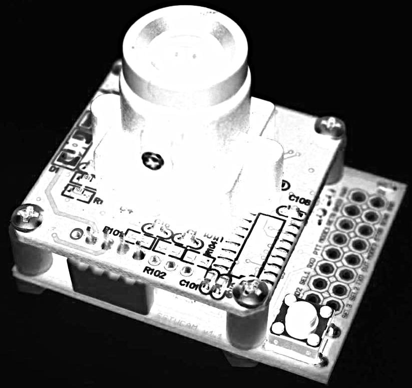
28 The Argent Data SSTVCAM module Page 28 The APRS payloads I designed as tracking back up for these flights use an Atmel 328p processor which controls a Cypress synthesiser chip with a 200 milliwatt amplifier stage. I modified Atmel APRS code originally designed by Gary Dion N4TXI ( by porting his code to work with an Arduino based system. This allows me to add custom telemetry fields to my APRS output and is easily modified under the popular Arduino environment. Since the main U.S. APRS calling frequency of MHz is very busy, I decided to add the capability to switch frequencies every other transmission. The board sends a position report on MHz, then switches to a clear channel (a nearby frequency such as MHz for example) and sends another short pack et report followed by slower speed RTTY data. The slower RTTY speed makes it possible to decode telemetry even in weak signal conditions and is a lot easier to DF a signal on a clear chan nel than on the almost constant traffic on the MHz APRS frequency. The SSTV CAM It was forecasted to be a beautiful Spring Day for the student launch so I decided to add a live Slow Scan Television down-link to one the APRS track ing transmitters. Scott Miller N1VG at Argent Data ( offers a very small SSTV camera board called the SSTVCAM. This uses a small TV camera module that captures a still image and serially sends the image data to the processor on the Argent Data board. The SSTV CAM is capable of sending down most of the pop ular SSTV modes. Although the image size is somewhat small, the quality on some of these modes is quite good. I chose the popular Scottie S2 mode which sends an image every 71 seconds. One nice feature is the ability to add a text message line above the image field in the Scottie modes which allowed me to display my callsign along with a sequence number and the altitude. The SSTVCAM board was easy to interface to my board. I just set the MODE lines to configure it for Scottie S2 mode, send the text header info via a serial port pin and then pulse the SEND line to start the SSTV transmission. I fed the audio line from the SSTV board to the APRS board and adjusted the solder jumpers on the SSTVCAM to get the proper audio level that I needed. My new live camera payload now sends APRS on MHz, switches to a clear channel and sends pack et, then 300 baud RTTY followed by the live SSTV
29 down-link and then repeats that sequence during the flight. Page 29 That provides a live SSTV image down link every two minutes from a very small and light weight module. There are a number of programs that you can use to decode the SSTV audio signal and many of them are freeware or shareware. Some favourites that do a great job are: MMSSTV, Ham Radio Deluxe (DM780), MultiPSK and MixW. There are even apps available for decoding with Smart Phones as well. Although it s great to view high resolution video recordings from a balloon flight after recovery, there is nothing like being to watch a live video down link during flight, particularly if you have a large group of spectators at your balloon event. Flight Day The two A&M University balloons lifted off about 36 minutes apart and headed on nearly identical flight paths due east towards the Chattanooga area. After the balloons burst near 90,000 feet the payloads parachuted back to Earth and landed about two miles apart in the Chickamauga, GA area. The first balloon landed on a ridge way up in a tree. Shane Wilson N4XWC tracked it down and after some effort managed to drag it all out of the tree. The second payload narrowly missed the trees and landed right in the middle of a cemetery for an easy recovery by Don Robinson WA4YYM, Gary Dion N4TXI, John Piccirillo W4JXP and the A&M students.

30 Using a netbook running MixW to decode the SSTV audio signal. Barry Lankford N4MSJ is captured taking a photo of the payload. Page 30

31 The SSTV signal worked great except that a piece of orange duct tape and bubble wrap man aged to cover the camera lens during the last part of the ascent. Fortunately, just after the balloon burst, the bubble wrap and duct tape moved away from the lens and we could view spectacular images of the descent, the black sky and the curve of the Earth, all in real time snapshots. Beautiful images were received as far away as 320 miles by Farrell Winder W8ZCF in Cincinnati, Ohio. Hank Cantrell W4HTB in Bowling Green, KY and Todd Morgan AL0I in Boone,NC both had great reception from over 150 miles away. Even the chase team could view the images on their laptop computers in their vehicles. SSTV images received by Hank Cantrell W4HTB in Bowling Green, KY from 150 miles away. Dayton Hamvention SSTV Balloon Page 31

32 Last year we launched a balloon from the Dayton Hamvention carrying a SSTV payload built by the ARBONET (Amateur Radio Balloons Over North East Texas) balloon group. This year we will fly two SSTV payloads on separate frequencies shortly after the Friday BalloonSat Forum. The ARBONET payload will fly again and I ll have one as well for two different views of the horizon and down at the Earth below. There will be ground sta tions set up in the Hamvention that will display the live images during the flight. Page 32

33 Alabama A&M University balloon payloads. Photo by Barry Lankford N4MSJ Page 33
34 WB8ELK APRS payload with SSTV (Real science is not possible without duct tape). Photo by Bev Teter Page 34

35 Page 35
36 The second AA&M balloon lifts off carrying the SSTV payload. Photo by Barry Lankford N4MSJ. Page 36
37 TV Amateur Page 37

38 Page 38
39 Page 39 TV Amateur is a German Language ATV Magazine It is published 4 times a year and if you would like to subscribe go to The current issue covers:- DVB-T to 70 cm with 2 MHz bandwidth Stereo 3D multiplexing of two synchronous Colour video signals DATV-compatible 23-cm up converter Print-to-screen (in PDF ebook) DATV in GMSK (prototype of the GMSK / QPSK mono Boards By DJ8DW) Space, Dayton Hamvention 2013T

40 Simple Pre-amplifier for DATV By Richard Carden VK4XRL Some set top boxes like the Jaycar XC 4914 or Strong STB 5006 don t have a lot of gain. However the information page on the XC 4914 is very good showing most parameters associated with the digital signal. Therefore some form of pre-amplifier may be needed. MiniKits (Aust) have one for 70cm. However a simple version using an ERA-3 can be used with a tuned input that works quite reasonable. The Page 40
41 circuit is shown below and can be fitted in a small diecast box. Tuning can be done with a received signal and adjusting the trimmer for minimum noise by looking at the waveform if you have those facilities or by just using the received picture. The ERA3 has a gain of 18.7 db with a noise figure of 2.8db. The output is rated at +13dbm at 2 GHz. It requires an operating voltage of around 3.2v and this can be obtained using a 251ohm resistor from +12v. This can be made from using parallel 470 and 560 ohm resistors or a 270 ohm resistor. Page 41 Happy DATV ing,
42 DATVtalk02 ATV and the Digital Fork in the Road Page 42 by Ken Konechy, W6HHC Reproduced from the newsletter of the Orange County Amateur Radio Club by kind permission. [Please Note This is the first article in series of articles to introduce Digital-ATV to hams for this new area of ham radio. The article was originally written in Since, 2009, there have been changes and improvements in technology but there is still a basic problem (most severe in US) that too few hams are using digital-atv. This article has been now updated to reflect the changes since 2009.] By now, everyone is using commercial Digital Television. Old commercial analog TV transmitters essentially went off the air in the US in June of 2009 and have been replaced by commercial digital TV transmitters. For several years before 2009 I had listened to some interesting ham conversations about we hams should change analog ATV over to Digital-ATV (aka DATV or D-ATV) to keep up with technology. This article is the result of my attempt to get my arms around digital ATV and be able to explain it to other hams. In this series, I plan to stay away from complex math equations (like used in Fast Fourier Transforms) and details of tedious algorithms used in the DVB protocols. Why Go Digital ATV? The main benefits of digital ATV are: 1. The picture quality can be nearly perfect much of the time 2. Digital techniques allow error correction from noise, multipath

43 3. Digital techniques allow advanced modulation (less bandwidth) and compression 4. Digital TV components will become more common on the marketplace. 5. Analog TV components will start to disappear from the marketplace. Page 43 Figure 1 - Comparison of analog ATV video and D-ATV video using the same antenna with weak sigs (courtesy of G7LWT & GB3HV) Different Types of Digital Video Broadcasting Specs To start with, there are three fundamental broadcasting environments for Digital Video broadcasting: Cable Satellite Terrestrial Each of these three different environments requires a different specification as described below.
44 DVB-C (cable) Page 44 The DVB-C standard for cable broadcasting was established by the Digital Video Broadcasting organisation ( The environment of cable is very low noise and very low loss. So resistance-to-noise is not needed for cable digital TV. The nice cable environment allows implementing higher order modulation schemes starting from QPSK up to 256QAM. Because of the need for a guaranteed low signal path loss in cable, this does not represent a good choice of technology for hams to consider. The more complex modulation technologies end up with less robustness to noise than the simple DVB-S standard (discussed latter). ITU-T_J.83-Annex B (cable) In the US, there is a variation of the DVB-T standard that is used by the US (and Canada) cable industry. The US standard for digital cable is called ITU-T_J.83-Annex B. However, ITU-T _J.83-Annex B still essentially reflects all of the strengths and weakness of the DVB-T standard. One advantage in the North America is that a ITU-T_J.83-Annex B transmitter can transmit directly on one of the frequencies used by a US cable-ready TV sets, without the use of a Set-Top-Box (STB). However, while these two cable protocols are similar to each other, their details make them incompatible with each other. DVB-S (satellite) The DVB-S standard for satellite broadcasting is designed to work in an environment that contains lots of signal path attenuation and line-of-sight communication. To compensate for the weak signals, the DVB-S standard uses different layers of Forward Error Correction (FEC) for a very robust protection against any kind of errors. One drawback for hams is that DVB-S was NOT designed to deal with multipath environment situations. Typically, the DVB-S uses MPEG-2 for video data compression and QPSK for modulation that can be run in a 2 MHz bandwidth mode. This is the standard chosen by many European and United States D-ATV groups for digitising ATV. DVB-T (terrestrial)

45 The DVB-T standard for terrestrial broad-casting by the Digital Video Broadcasting organisation is designed to work in the classic situation where a transmitter is broadcasting RF signals to home antennas coupled to a digital TV receiver. Page 45 Figure 2 Terrestrial reception using commercial set-top box
46 In over-the-air broadcasts, the terrestrial technology needs to overcome the destructive effects of multipath reflections. Also, the terrestrial signal path attenuation s can be frequency dependent and can result in a partly distorted received signal. The negative effects of multipath reflections can be reduced, by using 16QAM modulation for a low effective bitrate per carrier. To reduce the effective bitrate per carrier, DVB-T spreads out the bitrate over a large amount of carriers. This spreading out will result in 1,705 closely spaced carriers (using COFDM aka Coded Orthogonal Frequency Division Multiplexing) to create typically a 6 MHz bandwidth. If we look at the possibilities for D-ATV then hams will come to the conclusion that DVB-T can provide the ultimate approach if it comes to robustness. While the DVB-T standard provides for bandwidth s of 6 MHz, 7 MHz and 8 MHz, this wide bandwidth (compared to analog-atv) can transmit two video streams (2 video channels) on 6 MHZ so it is used by several DATV Repeaters to allow two separate up link channels that go out on a single DATV-T transmitter down link. Clever hams have bent the standard a little and redesigned the SDR software code to produce DVB-T signals for DATV that now occupy only 2 MHz of RF bandwidth. ATSC 8-VSB (terrestrial) What I have not mentioned, so far, is that the Digital Video Broadcasting organisation standards are only used for commercial TV in Europe and Asia.NOT in the United States. In the United States (and Canada) the commercial TV industry uses standards from the Advanced Television Systems Committee (ATSC) a spin-off from the old NTSC TV standards organisation. So again things are a little different in the US commercial digital television world for terrestrial broadcasts. 8-VSB is the 8-level Vestigial Sideband Modulation method adopted for terrestrial broadcast of the ATSC digital television standard. Like DVB-S, it usually uses MPEG-2 for video compression and multiple layers of Forward Error Correction (FEC) for a very robust protection against any kind of errors. Interestingly, the 8- VSB modulation does not use phase-shift techniques, but uses 8 levels of amplitude for modulation and demodulation. This modulation approach produces a gross bit rate of 32 Mbit/s, and a net bit rate of Mbit/s of usable data in a 6 MHz bandwidth. The net bit rate is lower due to the addition of forward error correction (FEC) codes. While, the set-top DTV boxes are very common, the current lack of low cost 8-VSB transmitting circuitry has prevented US hams from using this ATCS 8-VSB approach for ham radio D-ATV. Page 46
47 Drawbacks for D-ATV Page 47 There are two main drawbacks to D-ATV for ham radio ATV enthusiasts: 1) Weak Signal Reception Digital TV technology tends to have ALL or NOTHING video performance. The picture is GREAT thru noise and weakening signals.then POOF, it s gone. The transition phase between ALL or NOTHING tends to be very narrow. As Henry AA9XW explained in the Amateur Television of Central Ohio News (ATCO), Yes digital [ATV] is noise free until you hit the blue wall. There is 1 db between perfect and nothing. So don t expect a lot of DX since you can t find the signal in the noise without a spectrum analyser and BPF [band pass filter]. 2) High Cost of Equipment One advantage of analog ATV was the cost of equipment, especially transmitting equipment was relatively cheap. You could buy commercial analog CCTV equipment and easily modify it for ham radio ATV use. The receiving circuits can be obtained from old home satellite dishes (DVB-S) that are surplus on e-bay and can be converted to D-ATV. But, obtaining transmitters with image processing and the modulators is the main problem. There is no flood of cheap surplus satellite digital-transmitting equipment around. So you either buy boards from European D-ATV companies or you buy the Integrated Circuits used by transmitters and build your own equipment. In my opinion, this last approach takes a lot of engineering/software technical skill that most hams do not possess and requires an investment of a lot of time. SR-Systems in Germany offers a wide selection of printed circuit boards for D-ATV. Robbie KB6CJZ of OCARC estimates it costs about US$1,200 or more to buy a D-ATV transmitter exciter, digital band-pass filter, and very-linear power amp. A camera and a wide-bandwidth antenna would also be needed. D-ATV repeaters are more expensive.


48 Page 48 Status of D-ATV Today. Figure 3 Basic Block Diagram of DVB-S Transmitter for Digital-ATV Groups and clubs of D-ATV enthusiasts have shown that digital technology is possible for hams and works as expected. Fig 4 is a display of an early European DVB-S prototype transmitter demonstrated at the 2001 Friedrichshafen Ham Fair in Germany by Howard Sailer HB9JNX/AE4WA, Stefan Reimann DG8FAC, et al. The display is based on the block diagram shown in Fig 3. The compete article can be found in the TAPR Digital Communications Conference for DCC Proceedings 2001

49 Figure 4 Very early Prototype DVB-S D-ATV transmitter (courtesy of Thomas Sailer HB9JNX/AE4WA, et al.) Page 49


50 In my googling the Internet, participating in ATV/DATV forums and through having local conversations, I found that there was a very large burst of D-ATV efforts by hams (mainly in Europe) that lasted from about 2000 to about SR-Systems of Germany began producing what I called ham-grade boards (as compared to very very expense commercial Digital TV components) to allow hams to buy DATV components. At the same time AGAF, the ATV organisation in Germany, began sponsoring a project under the leadership of Professor Dr Uwe Kraus DJ8DW to also design and produce ham-grade DATV board components. The early activity level increases then went flat for a bit, and then a new project called DigiLite became finished in The BATC organisation offers a DVB-S kit for a transmitting exciter called DigiLite at a low total cost of less than US250. But, DigiLite is a kit. You have to order the individual components by yourself, and you need to solder the board, including the some surface-mount-devices (SMD aka SMT). About 250 of DigiLite transmitters have been sold as of Page 50 Figure 5 System Block Diagram of DigiLite Project DVB-S Digital-ATV Transmitter From what I have learned, there are only four or five areas in the US that have D-ATV repeaters or are even testing D-ATV. ATCO began the WR8ATV/R using digital DVB-S repeater output on 1268 MHz in central Ohio in 2004.
51 The COAR RACES group switched from analog-atv to DVB-S DATV for emergency video communications from the field back to the Emergency Operations Center (EOC) in the city of Orange, beginning in The San Diego / Del Mar ATV group (SDDM ATVG) completed a portable DVB-S DATV repeater in 2011 to be used for ARES and CERT activities. Jim KH6HTV (of KH6HTV Video) has been testing the robustness of the DATV ITU-T_J.83-Annex B protocol beginning in Colorado in The ATN Repeater group has begun testing an ITU-T_J.83-Annex B DATV repeater on 1243 MHz using QAM-64 modulation in the Los Angeles basin in early What is the Future for D-ATV? Based on what I have learned while first preparing this article on D-ATV, I am surprised by the small amount of current D-ATV activities in the United States. I expected a lot more activity in US in 2009 and I had hoped for a lot more activity in There is a great picture-quality-performance attraction for Digital TV. But, it seems to me that the weak signal picture loss associated with D-ATV may be taking some of the adventure of DX out of the equation. If I examine the needs of emergency communications groups (like RACES and ARES) to provide ATV video pictures back to an EOC.it was extremely difficult to get a little analog ATV (point-to-point) through the hills of Orange County. The testing of COAR RACES proved that D-ATV could overcome path loss difficulties and multipath reflections to deliver crystal clear picture video to the EOC. Finally, I personally find D-ATV technology quite complex. Since transmitters for D-ATV are expensive or you can design your own I find the complexity of designing my own D-ATV much much more complex than designing my own SSB transmitter or FM transmitter. I have also had a number of analog ATVers tell me that the technical complexities of DATV seem overwhelming they will stick with analog-atv. In addition, commercial standards continue to evolve. For example: The DVB-S spec is being commercially replaced by the newer DVB-S2 standard to accommodate the higher data bandwidth needed by High Definition DTV (HDTV). While DVB-S2 provides for faster data rates and provides better noise robustness (and even more complex - using new FEC scheme like Bose-Chaudhuri-Hocquengham), it also poses a possible threat to obsolete D-ATV equipment built with DVB-S designs? Page 51
52 In conclusion, it appears that the mainline analog ATV-ers in US are still passing up the the Digital Fork in the Road for D-ATV and continuing to use analog ATV. But, I am hopeful that I will see a big increase in D- ATV usage over the next five years. Only the cheap availability of cheap set-top boxes in US and more inexpensive D-ATV transmitters/components are probably able to improve the current situation. There is a ham radio project going on called the DATV-Express that plans to lower the cost a DATV exciter board using SDR approach. If this open-source project can successfully get their design manufactured this can help DATV move forward and become wider-spread among hams. I continue to be very much interested in D-ATV technology. If readers have other knowledge of D-ATV information and activities, and have other insights on the viability of D-ATV I would be delighted to hear from you. The author may be contacted at: W6HHC@ARRL.net D-ATV References and Links: Digital Video Broadcasting organisation (DVB) see Advanced Television Systems Committee (ATSC) see WHAT EXACTLY IS 8-VSB ANYWAY? see Digital Amateur TeleVision (D-ATV), by HB9JNX/AE4WA, et al see DigiLite Project for DATV (derivative of the Poor Man s DATV ) - see Charles-G4GUO blog on DATV-Express project development see Amateur Television of Central Ohio - see British ATV Club - Digital Forum - see OCARC library of newsletter DATV articles - see TAPR Digital Communications Conference proceedings (free downloads)- see Yahoo Group for Digital ATV - see CQ-TV magazine from BATC (mostly analog) see CQ-DATV online (free bi-monthly) e-magazine (epub format) see SR-Systems D-ATV components (Boards) see Page 52
53 KH6HTV Video D-ATV components (Transmitters) see Page 53
 On Saturday, August 3 rd at 1948 UT the Japanese HTV-4 cargo vessel was successfully launched to the International Space Station")

54 HamTV transmitter launched to ISS Page 54 Source - AMSAT-UK ( On Saturday, August 3 rd at 1948 UT the Japanese HTV-4 cargo vessel was successfully launched to the International Space Station (ISS). On-board was the HamTV transmitter and a number of CubeSats carrying amateur radio payloads. Front panel of the HamTV transmitter The Japanese space agency JAXA has announced details of four CubeSats on the launch. They will be deployed from the ISS by the JEM Small Satellite Orbital Deployer (J-SSOD) between October 2013 and March 2014.
, University of Tokyo, IHI aerospace. CW beacon on 437.250 MHz and 1k2 AFSK AX.25 telemetry on 437.")

.")
55 Page 55 PicoDragon CubeSat - Image credit VNSC The four CubeSats are: PicoDragon a 1U CubeSat developed by Vietnam National Satellite Center(VNSC), University of Tokyo, IHI aerospace. CW beacon on MHz and 1k2 AFSK AX.25 telemetry on MHz ArduSat-1 and ArduSat-X 1U CubeSats developed by Nanorack, NanoSatisfi. ArduSat MHz 9k6 MSK CCSDS downlink. ArduSat-X MHz 9k6 MSK CCSDS down link. TechEdSat-3 a 3U CubeSat developed by NASA Ames Research Center The company NanoRack has announced it is sending 36 Units of CubeSats to the ISS (believed to be 26 separate CubeSats, some 2U or 3U in size). At the time of writing it is believed they will be going on a later cargo vessel. A basic amateur radio station that should be able to receive HamTV from ISS - Image AMSAT- Italia
56 The main mission of HamTV is to perform contacts between the astronauts on the ISS and school students, not only by voice, but also by unidirectional video from the ISS to the ground within the ARISS program. Page 56 The ESA Columbus module on the ISS will host the 2.4 GHz video transmitting station in addition to the existing 144 MHz FM amateur radio station. This new equipment can broadcast images from the ISS during the school contacts or other pre-recorded video images up to 24 hours a day to allow ground stations tuning. It is planned to transmit DVB-S signals on 2.4 GHz at either 1.3Msps or 2.3Msps with 10 watts of RF. The IARU Amateur Satellite Frequency Coordination Panel have announced frequencies of MHz and MHz. HamVideo is the name of the on board DATV S-band transmitter. HamTV is the name of the complete system, comprising DATV down link and VHF voice uplink. Kaiser Italia SRL was the prime-contractor for the design and development of the flight and ground segment
57 DATV in GMSK (DM2CMB) Page 57 By Rainer Müller, DM2CMB, M2626 (reprinted from TV-AMATEUR 169 by kind permission) For digital ATV in Germany there are three modulation schemes in use: QPSK (from dig. satellite TV DVB-S), GMSK (from mobile phone) and OFDM (from dig. terrestrial TV DVB-T). Since 1999 the AGAF DATV developer team have presented DATV transmissions at HAMRADIO fair in Friedrichshafen, starting on 70 cm in GMSK, then on 23 and 13 cm in QPSK. From a hotel at the Pfaender mountain in Austria (overlooking the eastern part of Lake Constance) a 23 cm QPSK DATV signal was sent to the AGAF stand in the HAMRADIO hall in Friedrichshafen nearly every year since In 2003 the highlight was a 23 cm QPSK transmission from a flying Zeppelin above Lake Constance; in 2004 a 13 cm QPSK test from a ship, relayed on 23 cm to the HAMRADIO hall by DL0DTV at Pfaender mountain.

58 Page 58 Figure 1: Prototype of GMSK / QPSK mono Boards By DJ8DW, top The pioneering work was done from 1995 on at the chair of communications at Wuppertal University lead by Uwe Kraus, DJ8DW, supported by AGAF and DARC. Prof. Dr.-Ing. Uwe E. Kraus, DJ8DW, received the DARC Rudolf Horkheimer award 2002 on behalf of the DATV working group started a prototype construction project for 100 sets of MPEG-2-encoder and switchable GMSK/QPSK 70 cm exciter boards. AGAF distributed them world wide and contributed to the DATV development since then. Early tests in GMSK on 70 cm from Wuppertal to the Netherlands reached over more than 100 km distance and proved the benefits. With 2 Mbit/s and a bell-shape spectrum the skirts are at -20 dbc +-1 MHz from centre frequency. On 23 cm and higher bands 5 Mbit/s with higher bandwidth is possible, and using MPEG-4 video coding could halve the bandwidth at equal video quality. Contrary to QPSK and OFDM modulation schemes the GMSK signal can get amplified by non-linear PAs for FM-ATV without widening the spectrum.

59 This is cheap and accumulator friendly as well Page 59 The down side is: non-availability of cheap commercial receivers for GMSK-DATV. But there is a new prototype mono board V4 receiver developed by the team around Uwe, DJ8DW, and presented at the HAMRADIO fair Four different QRGs on 70 cm are available with rf bandwidth s between 2 and 6 MHz, so with a downconverter in front higher bands are possible. The received GMSK signal is converted into a QPSK type signal by the central FPGA chip and then provided on 1084 MHz at -40 dbm on the F-type output connector. The same output QRG is used for received QPSK signals. Figure 2: Prototype of GMSK/QPSK- mono boards, bottom. photos: DM2CMB A cheap commercial DVB-S receiver is doing the rest to provide video and audio signals, and even the supply current for the monoboard comes through this F-type connector.
60 For easier antenna alignment there is an analogue S-Meter output signal pin onboard as well as a 50 Ohm connector with a GMSK eye pattern signal. An additional MPEG-ASI connector is prepared, but needs a future FPGA software update for usage. The monoboard receiver is built on a four-layer PCB with European standard dimensions of 160 mm x 100 mm. Development of such complex kits for digital TV modes including the software is only for specialists, but we are glad that some radio amateurs are able to invest time and effort into it. Page 60 translation by Klaus, DL4KCK
61 The AGAF at Friedrichshafen 2013 Page 61 a report by our correspondent Klaus, DL4KCK Europe s biggest amateur radio fair had visitors, 500 more than The AGAF stand A1-247 was located in second row, behind foreign groups and adjacent to the DARA (Dayton-Hamvention organisers) who drew big crowds with their live streaming via the web, using their rolling tablet PC. A wink to the world was to be seen about 30 seconds later on the receiving monitor at their stand. Some recordings from hall A1 are available at

62 This is the state of the ATV crew working group on the HAMRADIO. Page 62


63 Page 63 A newly developed remote control (IQACT), so the ATV repeaters DBØQI could be controlled in Friedrichshafen On Friday Uwe,DJ8DW, opened the AGAF stand, showing live camera views of Lindau at Lake Constance on a big TV monitor via 23 cm DATV from his hotel at Pfaender mountain (Austria). Additionally he could switch via DTMF to a DVD player or a 13 cm DATV receiver for outside broadcasts from various mobile locations planned for Saturday. On a special table Uwe demonstrated his new GMSK/QPSK monoboard receiver for 70 cm in short-circuit operation.

64 Page 64 Figure 1: Prototype of GMSK / QPSK mono Boards By DJ8DW, top view On a big laptop monitor Klaus, DL4KCK, showed an early DATV test recording and provided some shutter glasses for a 3D video test.
. Page 65 e-mail distribution of TVA 169 has been taken up by many of the AGAF members.")
65 Besides older TV-AMATEUR issues the new electronic only version of TV-AMATEUR 169 was distributed on CD- ROM and supplemented by videos about the AGAF from 2012 including the historic PAL colour TV launch at WDR Cologne from 1963 to 1967 (showing interviews with German pioneers including Uwe,DJ8DW ). Page 65 distribution of TVA 169 has been taken up by many of the AGAF members. We have also had lots enquiries about the health of our chairman Heinz, DC6MR. He has had to recover at home from a slight stroke followed by two operations, but this did not stop him phoning his mates in Friedrichshafen by phone The planned outside broadcast operations for Saturday were rained off. Willi, DC5QC, manned our stand in
66 hall A1 together with his son Matthias, during our AGM. Where the old committee were re-elected for two more years - Heinz, DC6MR, had to run for office by correspondence. Page 66 Detlef, DH7AEQ, made a Skype contact to Berlin from our stand via his big laptop PC. ATV repeater sys-ops from Cologne and Eschweiler engaged in ATV via at HAMNET links and proved it by a live video contact from HAMRADIO to DB0KO near Cologne. The Munich ATV group (stand A1-551) tried a 10 GHz ATV link to DB0UTZ near Friedrichshafen, but were stopped by the metallic roof on hall A1. So they contacted HB9KB on a Swiss mountain instead - successfully.
67 Building The G3RFL YIG Transmitter Page 67 By Mike Berry, G1LWX In CQ-DATV1 there was an excellent article on a 10GHz ATV transmitter using a YIG by John, G3RFL. Up to date my only venture into 10GHz was via a gun diode and Bob Platt s board, so nothing ventured nothing gained, I set to build the board.

68 I used Johns artwork and using the press-n-peel system produced the board. After drilling all the holes for the Page 68
69 components, I started to populate the board. Page 69 I had ordered the Stellex mini YIG Osc type to 10.93GHz from RFBuy on E-Bay which arrived quite quickly from China. So after finishing the board I connected it up and switched on. Nothing: SIGH!!!!! I rechecked the connections and checked voltages etc but still no output. John suggested just connecting 8.5V to the bias and the YIG should give an output at half it s range i.e. around 10.5GHz. Still nothing although it was getting warm and drawing the correct current so in the end I took it up to John s as he is only just up the motorway. John confirmed my fears that the YIG was faulty so I contacted the seller who said that he checked every one!!!!! and for me to check the welding (lost in translation). I ed him back telling him that I had been building electronic equipment for 50 years and that there was nothing wrong with the welding, so he then asked me to send photographs which I did showing voltage and current and zero output. In the end he asked me to send it back and he would then send out a replacement. Now here was a problem. Sending anything back to China is fraught with risks. I had visions of the seller saying that he hadn t received the item it would then be up to me to chase it which would be difficult to say the least and could leave me $100 out of pocket. I opened a dispute through ebay before the 45 day deadline and explained the situation and I must say that the response was excellent. They sent me all the paperwork and even paid for the return postage also refunded me as soon as it had arrived at China customs where it has been for the last 3 weeks. In the meantime another one had been ordered (talk about fool and his money) which again arrived quite quickly. Back to the build
70 Connecting the YIG to 8.5 bias showed a healthy output 20mW at half it s tuning range GREAT. Page 70 With a spring in my step I mounted it to the board and made the connections. Dam it forgot to reverse the tuning coil connections. With that done I tuned it to 10.38GHz looking good.

71 What s that smell of burning under the board, SWITCH OFF QUICK. The 10 ohm 1W resistor feeding the fm Page 71
72 coil was red hot and fell off the board. I checked the fm coil which had a short to ground: not looking good. Page 72 I took the YIG off the board and checked the fm coil which was ok but was shorted to the body. This is looking bad, not another faulty one. I took a magnifying glass out and checked the connections. The wires that are connected to the YIG are connected by tiny push on connections one which had been pushed on too far and was causing the short phew. All looking good put the YIG back on the board now no output!!!! Checked the supply, no 8.5V, regulator gone, have I another, YES, good. Switched the soldering station back on, now it won t warm up above 100ºC. Switched everything off and took 2 paracetamol and went for a lie down in a dark room. Next day Repaired the soldering station and replaced the regulator, all now ok giving me 20mW at 10.38GHz on my Marconi 6960B rf meter, and connecting into a Down East Microwave 3-3PAK board gave a very healthy 1.9W. Smiling again. The unit has now been boxed up with my attempt at artwork (see photo above) using Microsoft publisher, then laminating and sticking to the box good enough for me. So all in all, quite a journey as they say. Faint heart never won a fair lady but then fools rush in were angel s fear to tread. Now all I need is a feed horn for my dish, but that s for another day.
73 Creating your own Test Card Page 73 By Richard Carden, VK4XRL Yes it s a Philips PM5544 test card but with CQ-DATV added. It is one of the preset test cards available at http;// but this site is so much more than preset test cards, there are all the elements available to quickly put together a test card of your own. The Test card maker software will enable you to design and create your own test card, by putting together premade patterns such as colour bars, grey scales, castellations and text. The preset items can be scaled and arranged in layers and then viewed, and re edited until you have your very own test card which can then be saved as a jpeg.
 Page 74")
74 Here is a rundown of some of the help file for your information; The individual parts from which you can create a test-card are called Objects and the completed test card is a tcd file which can be turned into a JPG or BMP file. Greyscales Solid blocks Alternating colour blocks (e.g. castellations, low-frequency gratings) Page 74
75 High frequency sine grating Colour gradients - Circles / ellipses - Boxes / frames Single straight lines Crossbars (corner stripes as seen on Test Cards C, D, E, F) Bulls eyes (sets of concentric rings as seen on many optical test cards) Sweeps (gratings of smoothly increasing frequency) Frequency Bursts (an more versatile type of grating) Star Bursts (radial frequency grating) Triangles Crosses (horizontal and vertical lines with optional solid background) Grid crosses (extra styling on grid lines as seen on Test Card F) Light spots (three optionally overlapping spots with colour bar colours) Text - Clocks (time, date or countdown) Pictures Page 75 For each of these, a position and size are specified, plus several other properties e.g. colour bar intensity, grating frequency, line thickness. Position and size are relative to the logical coordinate grid. There can be any number of each type of object in each layer of a TCD. Each TCD has several properties which can be amended, and which apply to every layer defined within the TCD: Title Aspect ratio Layer editor size Coordinate grid size Border size Forcing of square grid cells Alignment of grid to pixels (i.e. forcing each cell to be exactly the same size) Effective TV line frequency (for defining frequency bursts in MHz)
76 The following properties can also be amended separately for each individual layer: Page 76 Transparent or opaque background Background colour (if not transparent) Grid thickness and colour Position of physical grid relative to the card s logical grid Basic Use When you start up Test Card Maker or select File-New from the menu, you are presented with a default TCD consisting of single, blank layer with a mid-grey background. The aspect ratio is 4:3, editor size 512x384, with a 16x12 logical coordinate grid, and no physical grid. This automatic default can be switched off - see Options section.

77 Page 77 The menu contains four sub-menus: File, Edit, Layer and Tools (plus the About option which gives version information - currently there is also a HTML on-line help). File menu: the usual New, Open, Save, Save As, Close, and Exit, plus Close All, Properties and Viewer. Edit menu: Undo/Redo, Cut/Copy/Paste/Delete, Select All and Shift Set.
78 Layer menu: access to layer and grid properties, and manipulation of layers themselves (see Multi-Layer Test Cards ). Tools menu: Colour Cruncher tool, ToneBox tool, and Options. Page 78 To save a completed TCD (or indeed a work in progress) select File/Save from the menu or press Ctrl+S. To save it with a new name select File/Save As or press Ctrl+Shift+S. These options save the required information to a.tcd file - note that this does *not* create a bitmap. If you omit the.tcd extension it is added automatically. For new TCDs (indicated by in the title bar) File/Save behaves like File/Save As. To open a previously saved TCD select File/Open from the menu or press Ctrl+O. The File menu will also show the file names of the most-recently opened or saved TCDs (including from previous sessions). Choosing one of these options re-opens that TCD. Below the menu are a set of three buttons, followed by a row of nineteen. The first two buttons each pop up control panels, allowing access to the properties of the whole card (as per File/Properties) or the current layer (Layer/Properties). The next button (arrow in box) allows the definition of a selection area on the current layer, by clicking and dragging with the mouse. If you then click an add object button (see below) the new object s position and size default to that of the selection area. Alternatively if you click Edit/Select All or press Ctrl+A, only objects lying within the selection area are selected, rather than all the objects in the layer. The Select Area button stays down until one of these actions is taken or you click it again. The button after this (box with illuminated rectangles) is Select All. If you have defined a selection area, only objects in that area are selected, otherwise all objects in the current layer are selected. The remaining buttons allow objects to be added to the current layer. Each button has a schematic version of the object type; the status bar and tool-tip also indicate the object types when you move the mouse over the buttons.
79 Clicking any of these buttons brings up a properties control panel appropriate to the object type. Once an object has been added, its properties can still be altered, either by double-clicking on the object s active area (see below), or by editing it from the Layer Properties panel s object list. In either case this brings back the Object Properties panel. This panel also has a Delete button allowing the removal of objects. Note that if more than object is selected, only the object you double-clicked is deleted, not the whole set. Page 79 Viewer Displays the options specific to the Viewer. Start-up Mode Click a radio-button to determine what happens when you invoke the Viewer: Blank: Viewer does not draw the card automatically. Drawn: Viewer draws the card automatically but doesn t go into full-screen mode. Full: Viewer draws the card automatically and then goes into full-screen mode.

80 Here are a few Test cards that have been made using this software: Page 80 I could go on and place the whole Help file here but I won t, go and down load it and give it a try! You ll find it at; FML Home Page:

81 Page 81

82 Page 82 Testcard from Richard Carden Vk4XRL The above section of the help file was originally created 23/02/2001 by Steve Heap. comments to:
83 HF Testing of Video with 24 KHz bandwidth on 80M Page 83 A special thanks to Trevor M5AKA for passing along some links that were discussed on The Southgate Amateur Radio News and that centred on HF testing of video with 24 KHz bandwidth. The two reports were prepared by communications company, Rockwell Collins, were prepared for military customers in UK and US/Canada for tactical communications links. These reports say video so it can be considered a form of experimental digital-tv. The first report prepared by Rockwell Collins was called Wide Band HF UK Trials Summary. It describes trials for a tactical communications mode conducted for military customers in UK during The test report showed that: Ground wave testing frequencies were MHz (80M) and MHz and MHz Ground wave circuit testing distances were 40 miles Sky wave circuit testing frequencies were MHz and MHz and MHz Sky wave circuit testing distances were 400 miles Modulation was 64QAM RF Bandwidth was 24 KHz Payload data-rate was Kbps H.264 low rate video was achieved with colour at 15 frames per second streamed on HF in a bandwidth of just 18 khz.

84 Page 84
85 Ground Wave Tests Blandford Portsmouth (Approx 40 miles) (courtesy of Rockwell Collins) Page 85 The report is not clear on sorting out exactly what error correction technology was used for video. ARQ and Non-ARQ are mentioned for transmitting data, but that is all. The report did mention that on 80M, the Signal to Noise Ratios (SNRs) achieved using WBHF were typically low. The conclusion highlights did not speak well for complex digital modulations in weak signal conditions: Higher mode modulations (64 and 256 QAM) require high (>24dB) SNR and are more susceptible to multi-mode propagation effects. Higher bandwidth transmissions with lower modulations schemes proved resilient to interferer s. The first report can be found at: The second report prepared by Rockwell Collins discussed Over Air Test Results of WBHF Data Rates. It describes tests for a tactical communications modes conducted for military customers in US and Canada during Sky wave circuit testing frequencies were between 10 MHz and 11 MHz The primary sky wave testing distance was 1319 km (Cedar Rapids and Ottawa) Modulation was 32QAM, 64QAM, and 256QAM RF Bandwidth was 24 KHz FEC coding was used in tests 15 frames per second video, frame size scaled to data rate Signal-to-Noise-Ratio (SNR) range over the three days of 120 kbps testing varied from 27 db up to 44 db The second report can be found at: I find it interesting to learn what the big communications guys think is the correct combination of
86 technologies. Page 86 Trevor M5AKA points out that he suspects an approach like this may be the only way to get digital-tv on our 29, 50 and 144 MHz bands. 73 de Ken W6HHC
87 Multi-camera shoot - part 3 Page 87 by Trevor, G8CJS If I left you in the last issue drooling over ATEM, well in this issue I would like to introduce you to another solution called vmix. The advantage of ATEM was HDMI or SDI inputs good bye to PAL and its subcarrier patterning and hello to full resolution 16x9. But it did not get the best out of digital video. For instance Chromakey, and it is a little sparse on DVE effects, so let s have a look at another solution, this time it is a software only implementation. Let us start by watching the video
.")
88 Page 88 Cost Well the basic package is free and the full HD version is only $60 AUD ( 35). There is also time limited demo version for you to try for 60 days.
89 Free version Page 89 It has 2 Capture Inputs, 768x576, 1 Overlay Channel, and Recording, Streaming, Full screen Output, External Output. The $60 AUD ( 35) version has an extra capture input and is HD resolution1920x 1080 Streaming The most attractive feature of this unit is live streaming, and the big question is will it work with the BATC streaming site ( and the answer is yes visit the site pay your 4 membership and ask for a stream. For those of you who use the site with adobe live media interface, well this is a quantum leap it enables live clips and jpegs from your hard drive and of course external video sources (providing they are interfaced to you PC) I downloaded the free version and copied the streamer detail from my adobe Live Media encoder and it worked first time. What else has it got well I hope the picture of the control panel says it all, but let me list a few, just encase you missed the video. Effects 10 transitional effects Cut, Fade, Zoom, Wipe, Slide, Fly, Cross Zoom, Fly Rotate, Cube and Cube Zoom transitions Simultaneous Recording, Streaming and Output UStream, LiveStream and the BATC streamer, through Flash Media Live Encoder and Microsoft Expression Encoder. Live Record in full HD to AVI, MPEG-2 or WMV (I could not test this on my free version) Output via DeckLink capable cards to professional recording decks and monitors Built-In Title Templates Easily add and edit a Title or Score Board from the many built in templates

 Where do I get my copy http://www.vmix.com.")
90 Built-In Audio Mixer Audio Mixer allows you to easily keep track of all audio sources and includes the ability to Mute, Follow (Auto Mixing) and Delay any source. A VU Meter is also included with a peaking display to ensure each inputs level is broadcast ready. Tally Lights There is now a USB box and four cameras on air lights which also have a preview indicator $350Aud ( 211) (do I see a home construction project here??) Where do I get my copy Is there any support What do I like Well everything, it is ideal for streaming, and I suspect if I used a version above the free one I might be able Page 90
91 Page 91 to simultaneously record the steamed event to hard disc Is there a down-side Well only two camera inputs with the free version, but 3 with the 35 version which might enable streaming of a small event, off to ebay to find a digital capture card I bet that hurts.
92 VHF COMMUNICATIONS MAGAZINE Page 92 VHF Communications is a quarterly magazine only available by subscription. The subscription for 2013 is which includes UK and surface mail postage. Surface mail for overseas subscribers is available at 3.00 and airmail postage is an additional 5.00 for European subscribers and 8.00 for those outside Europe. For more information or to subscribe, contact us at the address below or visit The web site has sample articles and a full index from 1969 to the present that can be searched to find articles. Back issues are also available as pdf files on data DVDs. There are five different DVDs available: 1970s - All magazines from 1969 to 1979 for plus postage 1980s - All magazines from 1980 to 1989 for plus postage 1990s - All magazines from 1990 to 1999 for plus postage 2000s - All magazines from 2000 to 2009 for plus postage Bumber - All magazines from 1969 to 2009 for plus postage K M Publications, 503 Northdown Road, Margate, Kent, CT9 3HD, UK. Tel/Fax: +44 (0) , andy@vhfcomm.co.uk
93 Tracking the ISS Page 93 By Trevor Brown I know we are all thinking about receiving DATV from the International Space station and there are numerous problems to solve, the first one being tracking it with a suitable aerial as it passes over, and there are lots of solutions to this being bandied around on the various forums. My own thought was to move back to the days when we used to work as a team tracking the early OSCAR satellites. I have spent many a pass in the garden panning a crossed yagi by hand. So will this work for the ISS? Then I thought on some passes you can see the ISS, if you know where to look. Things have improved since the OSCAR and of course there are numerous free apps to help. So will a gun site on my Pan and tilt head coupled to a suitable array work?

94 Page 94 The ISS Detector app will tell you when and where to look for the International Space Station. You get an alarm a few minutes before a pass. The ISS Detector will also check if the weather conditions are right i.e. a clear sky for optimum spotting.
95 Page 95
96 A Complete History of ATV in Brisbane (or what I can remember) Page 96 By Richard Carden VK4XRL Introduction In 1934 television was first seen from experiments from the old Tower Windmill in Wickham Terrance, Brisbane. Also the first television transmission took place in Melbourne, both these systems used the mechanical system developed by John Logie Baird. National and Commercial television began in Sydney during 1956 with Channel 9 in September and followed by ABC in November and ATN 7 in December. Brisbane started in 1959 and further information can be found on the web via Goggle search etc.

97 Page 97
98 Page 98 ATV has been around for quite some time now in most States. Adelaide was very into the ATV scene with all equipment been built and shown at the Adelaide show. I met up with them in 1966 (Alan Nation and John Ingham). The first article I read on ATV was in Amateur Radio Action March 1958 in a nine part series on Amateur Television by E. E. Cornelius VK6EC/T. Notice the /T which was required when working ATV Mode also the frequency used was MHz. In Queensland (VK4) an article appeared in Amateur Radio Action Vol 2 No.9 (1979/1980) where mention was made of Peter Williamson- VK4ZWP/AWP (deceased). Peter and Graham Castledine (VK4KCE) decided to rekindle the interest in ATV after a visit to Bill Donovan s (VK4ZBD) shack in Chermside. A subsequent meeting between Peter Williamson, Graham Castledine and Tom Ivens was held to discuss ATV in Brisbane. In Victoria the Road Gang Ron Harrison-VK3AHJ and Ian Davis-VK3ATY (plus one other I have forgotten) had many articles and videos on ATV. A lot of people would remember the series by DJ4LB A Modular ATV TX. ATV Queensland

99 ATV in Brisbane Queensland started operations in the late 1970 early 1980 s when a group of Ham Radio operators in the Brisbane area wanted to set up a television repeater (see above). Before then all transmissions were of a simplex nature. By the early 80 s a repeater was in action. At first it was a low power operation from a house in Wavell Heights in the northern suburbs. After a few years, permission was granted to transmit from the Mains Road building at the inner city suburb of Spring Hill. The output frequency was in the 50 cm amateur band on Page 99
100 MHz vision with an audio carrier 5.5 MHz above that - in accordance with normal television procedure. Page 100 Output power was around 40 watts with vertical polarisation. It was later decided to changeover to horizontal polarisation as per the normal TV transmissions and the power was increased to around 100 watts ERP. A test pattern was transmitted from 0800 to 2400 hours when not in repeat mode. Input to the repeater was on MHz and reports were received over a wide area from amateurs including numerous non-amateur s tuning in as well, with many joining the club. Different antenna systems were tried to improve the performance and a Double Alford Slot antenna was constructed by club members (our thanks to VK5KTV for his input during that time) which provided Omni direction to improve the signal to all suburbs. Later a group of Hills Yagi antennas were used to provide better coverage, however these were later removed. During the late 80s and 1990s the club expanded to more than 64 members, with members from New Zealand, America, and most states here in Australia. With help from the technical group and especially to VK4BDB a large number of projects were available to members placing the club in a very good financial position. The first ever VSB transmitter was available for the first time in Australia and the club also produced a kit for a 23cm transmitter amongst other projects.

101 Page 101
102 Page 102 In 84 a special function was held to mark the 50th anniversary of the late Thomas Elliott s first experimental TV transmissions from the historic Tower Mill Observatory in Wickham Terrace. An interview by Tom Ives was made to highlight this occasion. Also the Golden Television Award was also made available to members for their contribution to the excellence in television experimentation. In 1990 the group took part in providing communications for the 75th anniversary of Lamington National Park. This involved the first use of 1250 MHz-FM using two-way video and audio links between O Reilly s Guest House and Binna Burra. The 1250 MHz-FM was the first use of the 23cm for ATV and also the Mitsubishi power module which was used from Binna Burra to O Reilly s and integrated into the overall event with direct linking to the ATV Brisbane repeater almost 100 km away. The FM transmitter was made a kit for the group by VK4XRL, VK4ADN and VK4BDB. Other activities have included a 40 km hook-up between Brisbane and Ipswich for the Engineers Society s Hawken Address, a link between schools on Moreton and Bribie islands with special thanks to VK4ADN, VK4BOB and VK4XRL. Who also provided many displays at various Hamfests here in Brisbane and on the Gold Coast. Jamboree of the Air was a major journey involving a repeater site on Camp Mountain with special thanks to Parks and Wildlife for allowing us to be there. In October 1990 the group took part in the historic satellite relay (with thanks to VK4BDB) throughout Australia from the Gladesville ATV club in Sydney. A special video was supplied by VK4BOB and VK4XRL to mark the occasion and still can be seen on YouTube (
 to fit in with the band plan for mainstream UHF TV, as directed by the Department of Communications.")
103 The 50 cm band which we were using was also used for UHF television therefore the frequency was adjusted to MHz (channel 35) to fit in with the band plan for mainstream UHF TV, as directed by the Department of Communications. During the early 2000 s the group had to relinquish the 50 cm band altogether and moved to an output frequency of MHz in the 70 cm band. The input frequency was changed to 1283 MHz FM in the 23 cm band for better quality. The repeater eventually had a call sign change to VK4RMG and was temporarily located at Mt Glorious to the west of Brisbane and then to Wamuran in the Page 103
104 north. It did currently sit at Ocean View, however it only transmitted on demand and on Wednesday for Club Call back. (See under Digital for latest information). Page 104 Also during the 1990 s the group was involved with ATV hook-ups between schools in the rural area west of Brisbane, however and unfortunately due to a difference of opinions the group broke up into two ATV groups and another repeater VK4RKC was born and brought into operation at Ocean View. This group wanted to see changes made, keeping up with new technology and not be tied to the same old system. The start of digital transmissions In 2002 digital was transmitted by this group by VK4KI and VK4XRL on 1250-MHz using the DVB-S system from SR-System with thanks from Stefan of SR-Systems. This was later added as a repeater input. In 2005 it was then decided to go digital as an output from the repeater using DVB-T as per the commercial and National specifications, allowing P5 pictures to all that could see the repeater. This was added with great enthusiasm as now all could see what can be achieved by going digital. Since then all members of the Brisbane Digital ATV Group have gone digital on 1250-MHz. A number of clubs also use the repeater for their club activities using FM and therefore we have a lot more viewers watching the transmissions from VK4RKC. The audio sub-carrier has also been changed to 6MHz which reduces the beat pattern between it and the colour sub-carrier. Now with the advent of losing the lower end of the 70cm band the digital repeater was to cease transmission on MHz at midnight on the 31st December Negotiations with the SEQATV group on three occasions for joint co-operation had failed where we offered them the use of the second transport stream on our repeater with a view of changing the output frequency to MHz. This was rejected and they decided to provide a digital system of their own at considerable cost. Since then members of the Digital group have since combined with the SEQATV group in a view of promoting the ATV hobby as it was before the split and a new executive committee was elected at the last AGM. Three questions now being address are;
105 1. What s good for the Club? 2. What s the best for the mode (ATV)? 3. What s best for the hobby? Page 105 The club had voted to buy the digital repeater from those that built it, however that hasn t happened as the costs were too high and no money was forth coming? The group has plans to interlink certain repeaters from around the South East Queensland area using 5.8 MHz. The two web sites are as follows; Brisbane Digital ATV Group; SEQATV CLUB (needs updating); Please contact the club at bdatvg@people.net.au for further information or photos that reflect early ATV activities or if you require help with this exciting aspect of Amateur Radio. Thanks to Graham Castledine (VK4KCE) for his input from those early days of ATV in Brisbane. Further interesting reading can be found in the following books; 50 Years of ABC Technical Services Alright Leaving Here by Doug Grant and SPINNING DISCS, MIRRORS AND ELECTRONS by Robert Forster, and Douglas Grant
106 Page 106

107 Caption contest Page 107 Just for fun. Last issues picture is shown below. On my copy of the script it says blue screen against this scene, might be a little late to point that out to the director -Trevor So that s where the word HANGOVER comes from. or Sorry that s another Secret Committee meeting I will be missing. - John G3RFL
108 Now, wave to us with both hands Regards, G8KZN. Page 108 I know the film is a remake of Picnic at Hanging rock, but I do not remember this scene in the original - Trevor I think this is taking portable operation a bit too far - Mike G1LWX I need to go to the rest room, it s where over there or The rope winding mechanism over there and it is hand operated - Roger, G4OCO We re not coming back until the September issue is released - Richard VK4XRL And the winner is.. Mike G1LWX - congratulations. This issues picture is shown below.

109 Page 109
110 Please send your entries to Page 110
111 Information External links If you have an ebook reader that does not have Wi-Fi then you will not be able to use the hyper-links in this publication. If you have an ebook reader that has Wi-Fi then you will be able too providing you are in a Wi-Fi zone. But if you have a Kindle 3G then yes, but only to Amazon, and there is not a lot of ATV material on their site. Smart phone reading apps are ok providing that you have a 3G data connection. Note: These links will fire up your devices browser and if you are using 3G/4G then you will incur data usages charges. Legal Niceties (the small print) E&OE. Whilst every care is taken in the production of this publication, dotmobi accepts no legal responsibility for the advice, data and opinions expressed. dotmobi neither endorses nor is it responsible for the content of advertisements or the activities of those advertisers. No guarantee of accuracy is implied or given for the material herein. dotmobi expressly disclaims all liability to any person in respect of anything and in respect of the consequences of anything done or omitted to be done wholly or partly in reliance upon the whole or any part of this publication. As the regulations for the operation of radio frequency equipment vary in different countries, readers are advised to check that building or operating any piece of equipment described in dotmobi will not contravene the rules that apply in their own country. All copyrights and trademarks mentioned in this publication are acknowledged and no infringement of the intellectual copyright of others is intended. Page 111
112 Notice to Contributors Page 112 Authors are alone responsible for the content of their articles, including factual and legal accuracy, and opinions expressed by them may not reflect the editorial stance of the publication. Material submitted to dotmobi should not infringe the copyright of other writers or bodies. Contributions are accepted for publication on this basis alone. dotmobi publications -

113 Next issue Page 113. and so much more! Don t panic - we are sure to find some interesting stuff for you to read in the next issue. If you would like to contribute then please contact editor@cq-datv.mobi This ebook is displayed using 100% recycled electrons.
2013 ARRL/TAPR DCC. DATV-Express
 2013 ARRL/TAPR DCC a Testing Report by Art Towslee towslee1@ee.net Ken Konechy W6HHC@ARRL.net WA8RMC W6HHC The Presentation Authors. Art WA8RMC Ken W6HHC 2 103 Status of Digital-ATV Today Video Quality
2011 ARRL TAPR Digital Comm Conference
 2011 ARRL TAPR Digital Comm Conference by Charles Brain G4GUO@ARRL.net Ken Konechy W6HHC@ARRL.net G4GUO W6HHC Status of Digital-ATV Today Video Quality of DATV far exceeds analog-atv Very few hams transmitting
TechTalk123 - The MiniTiouner Receiver/Analyzer for Digital-ATV
 TechTalk123 - The MiniTiouner Receiver/Analyzer for Digital-ATV by Ken W6HHC Jean-Pierre F6DZP has been modifying Digital-ATV receivers for DVB-S protocol with software for years - in order to allow the
Update on DATV-Express exciter for Digital-ATV
 2015 ARRL/TAPR DCC by Update on DATV-Express exciter for Digital-ATV Ken Konechy W6HHC W6HHC@ARRL.net Abstract - The old technology of analog-atv suffers from susceptibility to snow and multi-path ghost
TechTalk #83 #74 DATV Testing Report Amateur Television (ATV) - Part 3 (Bench Testing)
 - Part 3 (Bench Testing)") TechTalk #83 #74 DATV Testing Report Amateur Television (ATV) - Part 3 (Bench Testing) - - The by Digital Ken Konechy Fork in W6HHC the Road - - & Robbie Robinson KB6CJZ In TechTalk77, we provided a testing
TechTalk #83 #74 DATV Testing Report Amateur Television (ATV) - Part 3 (Bench Testing) - - The by Digital Ken Konechy Fork in W6HHC the Road - - & Robbie Robinson KB6CJZ In TechTalk77, we provided a testing
Getting started in Amateur Television. BATC - August 2016
 Getting started in Amateur Television BATC - August 2016 Getting started in ATV What is ATV? Which band and where? Analogue or digital? BATC video portal How do I get on air? It s not all about radio!
DATV on ISS? How can this become a reality? Wolf-Henning Rech DF9IC / N1EOW Thomas Sailer HB9JNX / AE4WA
 DATV on ISS? How can this become a reality? Wolf-Henning Rech DF9IC / N1EOW Thomas Sailer HB9JNX / AE4WA UoS 8.2005 Wolf-Henning Rech DF9IC 1 Use open worldwide commercial broadcast standards - this ensures
Receiving DATV on four bands with Digital Satellite TV equipment
 Receiving DATV on four bands with Digital Satellite TV equipment By Grant VE3XTV Background: ATV started out on the 70 cm BAND using AM modulation and all contacts were made via simplex. The receivers
The GB3HV digital project part 1. Noel Matthews G8GTZ
 The GB3HV digital project part 1 Noel Matthews G8GTZ Introduction The Home Counties ATV Group has run GB3HV, the 23cms ATV repeater from a site in High Wycombe (IO91OO) for over 14 years giving good coverage
Getting started in Amateur Television. Noel Matthews G8GTZ
 Getting started in Amateur Television Noel Matthews G8GTZ Getting started in ATV What is ATV? Which band and where? Analogue or digital? BATC video portal How do I get on air? It s not all about radio!
Es'hail-2 (P4-A), the first geostationary OSCAR from Qatar
, the first geostationary OSCAR from Qatar") Es'hail-2 Es'hail-2 (P4-A), the first geostationary OSCAR from Qatar Presentation Credits: Peter Gülzow, DB2OS AMSAT-DL President, G3VZV and DH2VA Earth Coverage Es'hail-2 AMSAT Payload Block Diagram -
Es'hail-2 Es'hail-2 (P4-A), the first geostationary OSCAR from Qatar Presentation Credits: Peter Gülzow, DB2OS AMSAT-DL President, G3VZV and DH2VA Earth Coverage Es'hail-2 AMSAT Payload Block Diagram -
A LOW COST TRANSPORT STREAM (TS) GENERATOR USED IN DIGITAL VIDEO BROADCASTING EQUIPMENT MEASUREMENTS
 GENERATOR USED IN DIGITAL VIDEO BROADCASTING EQUIPMENT MEASUREMENTS") A LOW COST TRANSPORT STREAM (TS) GENERATOR USED IN DIGITAL VIDEO BROADCASTING EQUIPMENT MEASUREMENTS Radu Arsinte Technical University Cluj-Napoca, Faculty of Electronics and Telecommunication, Communication
A LOW COST TRANSPORT STREAM (TS) GENERATOR USED IN DIGITAL VIDEO BROADCASTING EQUIPMENT MEASUREMENTS Radu Arsinte Technical University Cluj-Napoca, Faculty of Electronics and Telecommunication, Communication
Digital Amateur TeleVision (D-ATV)
") Digital Amateur TeleVision (D-ATV) Thomas Sailer, HB9JNX/AE4WA, Wolf-Henning Rech, DF9IC/N9EOW, Stefan Reimann, DG8FAC, Jens Geisler, DL8SDL August 7, 2001 Abstract In this article, we present a Digital
Digital Amateur TeleVision (D-ATV) Thomas Sailer, HB9JNX/AE4WA, Wolf-Henning Rech, DF9IC/N9EOW, Stefan Reimann, DG8FAC, Jens Geisler, DL8SDL August 7, 2001 Abstract In this article, we present a Digital
70cm & Microwave Amateur TV Frequencies Jim Andrews, KH6HTV
 AN-10b TV Frequencies.doc (kh6htv, 5/19/2015) p. 1 of 8 Application Note AN-10b copyright - Nov. 2011 rev. a - Oct. 2014 rev. b - May 2015 70cm & Microwave Amateur TV Frequencies Jim Andrews, KH6HTV www.kh6htv.com
Amateur Television in the UK. Noel Matthews G8GTZ
 Amateur Television in the UK Noel Matthews G8GTZ UK overview About 100 active ATV operators Mainly centred around repeaters Migration to digital happening but still a lot of FM around DVB-S 2 and 4 Msymbols
DC-099 FPV/UAV DTV CAM Module
 DC-099 FPV/UAV DTV CAM Module DTV CAM DTV CAM is an all-new camera which outputs the captured HD video in digital TV signal. The core technology is based on open industrial standard EN 300-744 DVB-T, which
D5: INTEGRATING HIGH DEFINITION DIGITAL AMATEUR TELEVISION INTO YOUR HAM STATION. Mel Whitten, KØPFX
 D5: INTEGRATING HIGH DEFINITION DIGITAL AMATEUR TELEVISION INTO YOUR HAM STATION Mel Whitten, KØPFX mel@melwhitten.com For Amateur Television Digital Video Broadcasting Systems Manufacture Topics... What
DIVERSITY DVB-T RECEIVER (DDR)
") User s Manual The most important thing we build is trust. DIVERSITY DVB-T RECEIVER (DDR) Cobham Surveillance GMS Products 1916 Palomar Oaks Way Ste 100 Carlsbad, CA 92008 100-M0062X2 T: 760-496-0055 05/15/09
User s Manual The most important thing we build is trust. DIVERSITY DVB-T RECEIVER (DDR) Cobham Surveillance GMS Products 1916 Palomar Oaks Way Ste 100 Carlsbad, CA 92008 100-M0062X2 T: 760-496-0055 05/15/09
DQT1000 MODEL DIGITAL TO QAM TRANSCODER WITH DIGITAL PROCESSING AND MULTIPLEXING
 MODEL DQT1000 DIGITAL TO QAM TRANSCODER WITH DIGITAL PROCESSING AND MULTIPLEXING The R. L. Drake model DQT1000 is a professional quality, digital headend transcoder product that tunes and demodulates MPEG2
Notes on Using Hi-Des DVB-T Products with KH6HTV Video -- RF Linear Power Amplifiers Jim Andrews, KH6HTV
 AN-18 HiDesNotes.doc (kh6htv, rev. 10/30/14) p. 1 of 9 Application Note AN-18 copyright - Sept, 2014 Revised - Oct. 2014 Notes on Using Hi-Des DVB-T Products with KH6HTV Video -- RF Linear Power Amplifiers
Second, Re-Evaluation of Hi-Des, Model HV-320E, DVB-T, Modulator Jim Andrews, KH6HTV
 p. 1 of 7 Application Note AN-42 copyright December, 2017 Second, Re-Evaluation of Hi-Des, Model HV-320E, DVB-T, Modulator Jim Andrews, KH6HTV Fig. 1 Hi-Des model HV-320E, DVB-T, Modulator In March / April,
TV4U QUAD DVB-S2 to DVB-C TRANSMODULATOR
 INSTRUCTION MANUAL Features of the new DVB-C transmodulators line Through the use of the FPGA technology the transmodulators provides the highest performance at the lowest price. Four carriers are formed
Amateur TV Receiver By Ian F Bennett G6TVJ
 Amateur TV Receiver By Ian F Bennett G6TVJ Here is a design for an ATV receiver which makes use of a Sharp Satellite tuner module. The module was bought from "Satellite Surplus" at a rally a year or so
Easy HD Expressway! HDMI/Composite(CVBS) to DVB-T/ISDB-T/ISDB-Tb
 to DVB-T/ISDB-T/ISDB-Tb") HV-200 Professional 4-band (100MHz~2500MHz) Full HD Digital TV Modulator HDMI/Composite(CVBS) to DVB-T/ISDB-T/ISDB-Tb HV-200 is the most cost-effective solution to distribute HDMI or composite (CVBS) video
HV-200 Professional 4-band (100MHz~2500MHz) Full HD Digital TV Modulator HDMI/Composite(CVBS) to DVB-T/ISDB-T/ISDB-Tb HV-200 is the most cost-effective solution to distribute HDMI or composite (CVBS) video
DC-100 DTV CAM Series
 DC-100 DTV CAM Series DTV CAM DTV CAM is an all-new camera which outputs the captured HD video and audio in digital TV signal. The core technology is based on open industrial standard EN 300-744 DVB-T,
!! 1.0 Technology Brief
 1.0 Technology Brief Table of Contents Contents Scope... 3 Some Satellite Television Principles... 3 Compression... 3... 3 91 Degrees West Longitude... 4 82 Degrees West Longitude... 5 Distribution Technology...
DC-103(1080P)/DC-102(720P) DTV CAM Bare bone
/DC-102(720P) DTV CAM Bare bone") DC-103(1080P)/DC-102(720P) DTV CAM Bare bone DTV CAM DTV CAM is an all-new camera which outputs the captured HD video in digital TV signal. The core technology is based on open industrial standard EN 300-744
DC-103(1080P)/DC-102(720P) DTV CAM Bare bone DTV CAM DTV CAM is an all-new camera which outputs the captured HD video in digital TV signal. The core technology is based on open industrial standard EN 300-744
Multimedia Standards
 Multimedia Standards SS 2012 Lecture 12 Prof. Dr.-Ing. Karlheinz Brandenburg Karlheinz.Brandenburg@tu-ilmenau.de Contact: Dipl.-Inf. Thomas Köllmer Dr.-Ing. Uwe Kühhirt thomas.koellmer@tu-ilmenau.de uwe.kuehhirt@idmt.fraunhofer.de
DC-103 FPV 1080P Full HD DTV CAM
 DC-103 FPV 1080P Full HD DTV CAM Supporting 70~450MHz and 850~950MHz bands (optional 1.2G band) DTV CAM DTV CAM is an all-new camera which outputs the captured HD video in digital TV signal. The core technology
Slow Scan TV. What is it? How to get started? What it can be! by Ed Poccia, KC2LM. Friday, January 19, 18
 Slow Scan TV What is it? How to get started? What it can be! by Ed Poccia, KC2LM What is Slow Scan TV? image transmission mode using audio tones used by hams to send each other grainy pictures different
REGIONAL NETWORKS FOR BROADBAND CABLE TELEVISION OPERATIONS
 REGIONAL NETWORKS FOR BROADBAND CABLE TELEVISION OPERATIONS by Donald Raskin and Curtiss Smith ABSTRACT There is a clear trend toward regional aggregation of local cable television operations. Simultaneously,
AMD-53-C TWIN MODULATOR / MULTIPLEXER AMD-53-C DVB-C MODULATOR / MULTIPLEXER INSTRUCTION MANUAL
 AMD-53-C DVB-C MODULATOR / MULTIPLEXER INSTRUCTION MANUAL HEADEND SYSTEM H.264 TRANSCODING_DVB-S2/CABLE/_TROPHY HEADEND is the most convient and versatile for digital multichannel satellite&cable solution.
Evaluation of New Hi-Des, Model HV-120A, DVB-T, Receiver Jim Andrews, KH6HTV
 p. 1 of 5 Application Note AN-27 copyright March, 2016 Evaluation of New Hi-Des, Model HV-120A, DVB-T, Receiver Jim Andrews, KH6HTV In the spring of 2014, I had become aware of the amateur DVB-T supplier,
Easy HD Expressway! HV-100E/HV-100J/HV-100EH Full HD Digital TV Modulator. HDMI/Composite(CVBS) to DVB-T/ISDB-T/ISDB-Tb
 to DVB-T/ISDB-T/ISDB-Tb") Easy HD Expressway! HV-100E//HV-100EH Full HD Digital TV Modulator HDMI/Composite(CVBS) to DVB-T/ISDB-T/ISDB-Tb HV-100 is the most cost-effective solution to distribute HDMI or composite (CVBS) video to
Easy HD Expressway! HV-100E//HV-100EH Full HD Digital TV Modulator HDMI/Composite(CVBS) to DVB-T/ISDB-T/ISDB-Tb HV-100 is the most cost-effective solution to distribute HDMI or composite (CVBS) video to
Introduction This application note describes the XTREME-1000E 8VSB Digital Exciter and its applications.
 Application Note DTV Exciter Model Number: Xtreme-1000E Version: 4.0 Date: Sept 27, 2007 Introduction This application note describes the XTREME-1000E Digital Exciter and its applications. Product Description
Getting Started In SSTV
 Getting Started In SSTV Umesh Ghodke,, South Bay Amateur Radio Association Slow Scan Scan Television (SSTV) Transmission of static pictures via radio. Monochrome or color Takes a couple of minutes per
Ultra-ViewRF 8HD Director Monitor. User Operation Manual
 Ultra-ViewRF 8HD 5.8GHz Wireless Director Monitor User Operation Manual 17.1.2013 v2_7 Video Equipment Rentals - VER 912 Ruberta Avenue Glendale, CA 91201 - U.S.A. Office 818-956-1444 Table of Contents
KTVN Silver Springs DTV Translator. K29BN D in KTVN Shop
 KTVN Silver Springs DTV Translator K29BN D in KTVN Shop The Harris/Gates Air UAX 100 translator has passed the weekly on air at full power into the dummy load and is ready to be transported to the site
HEVC H.265 TV ANALYSER
 INTRODUCING THE WORLD S FIRST HEVC H.265 METER & TV ANALYSER Digital terrestrial TV is at the dawn of a new transformation driven by the need to release yet further spectrum in the so called second dividend
SPECIFICATION. Multistandard Demodulator tuner. ATSC/Legacy analog NTSC/BTSC
 1.Feature MATSCA-SF is the Multistandard Demodulator ATSC/QAM/NTSC module which integrates product is especially suitable for PVR or PIP-TV application. - Supported modulation standards:. ATSC digital
HD-SDI/HDMI to DVB-T/ISDB-T/ISDB-Tb
 HV-202 Professional 4-band (100MHz~2500MHz) Full HD Digital TV Modulator HD-SDI/HDMI to DVB-T/ISDB-T/ISDB-Tb HV-202 is the most cost-effective solution to distribute HDMI or composite (CVBS) video to unlimited
The implementation of HDTV in the European digital TV environment
 The implementation of HDTV in the European digital TV environment Stefan Wallner Product Manger Terrestrial TV Transmitter Systems Harris Corporation Presentation1 HDTV in Europe is an old story! 1980
AVE HOME FAGOR CVBS TO DVB-T ENCODER MODULATOR. Fagor Electr6nica
 AVE HOME CVBS TO DVB-T ENCODER MODULATOR FAGOR Fagor Electr6nica TABLE OF CONTENTS 1. SPECIFICATIONS... 12 1.1 Product Overview... 12 1.2 Appearance and Description... 12 1.3 Diagram... 13 1.4 Characteristics...
MOBILE DIGITAL TELEVISION. never miss a minute
 MOBILE DIGITAL TELEVISION never miss a minute About Mobile DTV The Power of Local TV on the Go Mobile Digital Television (DTV) represents a significant new revenue stream for the broadcasting industry
News from Rohde&Schwarz Number 195 (2008/I)
") BROADCASTING TV analyzers 45120-2 48 R&S ETL TV Analyzer The all-purpose instrument for all major digital and analog TV standards Transmitter production, installation, and service require measuring equipment
BROADCASTING TV analyzers 45120-2 48 R&S ETL TV Analyzer The all-purpose instrument for all major digital and analog TV standards Transmitter production, installation, and service require measuring equipment
Laboratory platform DVB-T technology v1
 Laboratory platform DVB-T technology v1 1. Theoretical notions Television can be defined as a set of principles, methods and techniques used for transmitting moving images. The essential steps in television
Microwave PSU Broadcast DvB Streaming Network
 Microwave PSU Broadcast DvB Streaming Network Teletechnika Ltd. is in the mainstream of telecommunication since 1990 Main profile of the company Development Manufacturing Maintenance Segments Microwave
RiniLink R1000_SG. Covert Wireless Digital Surveillance COFDM System
 Covert Wireless Digital Surveillance COFDM System Digital video covert surveillance system Non-line-of-Sight Operation Body worn Compact and Lightweight Digital Encryption Frequency 400 MHz, 800 MHz, 1.3
Easy HD Expressway! HV-100E/HV-100J/HV-100EH Full HD Digital TV Modulator. HDMI/Composite(CVBS) to DVB-T/ISDB-T/ISDB-Tb
 to DVB-T/ISDB-T/ISDB-Tb") //H Full HD Digital TV Modulator HDMI/Composite(CVBS) to DVB-T/ISDB-T/ISDB-Tb HV-100 is the most cost-effective solution to distribute HDMI or composite (CVBS) video to unlimited standard TV s without
//H Full HD Digital TV Modulator HDMI/Composite(CVBS) to DVB-T/ISDB-T/ISDB-Tb HV-100 is the most cost-effective solution to distribute HDMI or composite (CVBS) video to unlimited standard TV s without
AT2780USB. Digital Video Interfacing Products. DVB-T/H/C & ATSC Modulator IF and RF ( VHF & UHF ) Output DVB-ASI & DVB-SPI Inputs
 Output DVB-ASI & DVB-SPI Inputs") Digital Video Interfacing Products AT2780USB DVB-T/H/C & ATSC Modulator IF and RF ( VHF & UHF ) Output DVB-ASI & DVB-SPI Inputs Standard Features DVB-T/H/C Modulator with VHF & UHF Up converter. - High
Digital Video Interfacing Products AT2780USB DVB-T/H/C & ATSC Modulator IF and RF ( VHF & UHF ) Output DVB-ASI & DVB-SPI Inputs Standard Features DVB-T/H/C Modulator with VHF & UHF Up converter. - High
SingMai Electronics SM06. Advanced Composite Video Interface: HD-SDI to acvi converter module. User Manual. Revision 0.
 SM06 Advanced Composite Video Interface: HD-SDI to acvi converter module User Manual Revision 0.4 1 st May 2017 Page 1 of 26 Revision History Date Revisions Version 17-07-2016 First Draft. 0.1 28-08-2016
AMIGO- 8VSB (ATSC) digital Modulator
 digital Modulator") - 8VSB (ATSC) digital Modulator With Linear & Non-Linear Pre-Distortion for HDTV Overview The LUMANTEK line of Solid State VHF/UHF 8VSB Digital Modulators offers an unparallel combination of features and
- 8VSB (ATSC) digital Modulator With Linear & Non-Linear Pre-Distortion for HDTV Overview The LUMANTEK line of Solid State VHF/UHF 8VSB Digital Modulators offers an unparallel combination of features and
HV-100E/HV-100J HD HDMI/Composite AV Sender. DVB-T/ISDB-T Digital TV Modulator
 HV-100E/ HD HDMI/Composite AV Sender DVB-T/ISDB-T Digital TV Modulator HV-100 is the most cost-effective solution to distribute HDMI or composite (CVBS) video to unlimited standard TV s without requiring
We changed the way measurements are made! North American edition
 We changed the way measurements are made! North American edition One model for every need Select yours LCD size LCD aspect ratio Transflective LCD US TV EXPLORER 5.5 4:3 US TV EXPLORER II 6.5 16:9 Cable
RF SIGNAL GENERATOR. RF Signal Generator for Digital Broadcasts LG 3810 RF SIGNAL GENERATOR SIGNAL GENERATOR GENERAL FEATURES
 RF SIGNAL for Digital Broadcasts LG 3810 RF SIGNAL GENERAL The LG 3810 is an RF signal generator with optional encoders that can be installed to add support for the standards of a variety of digital broadcast
SPECIFICATION. DVB-T/ DVB-C / Worldwide hybrid Switchable NIM Tuner
 1.Feature *. Integrated RF switch, NTSC VIF demodulator, COFDM demodulator *. All-in-one full NIM function with compact size, optimal solution for cost reduction and shortening product development lead-time.
Digital Television Fundamentals
 Digital Television Fundamentals Design and Installation of Video and Audio Systems Michael Robin Michel Pouiin McGraw-Hill New York San Francisco Washington, D.C. Auckland Bogota Caracas Lisbon London
VENTUS 1.0 All in One USB Type of DTV / Mobile TV Signal Generator
 to be Better or to be Different LUMANTEK VENTUS 10 All in One USB Type of DTV / Mobile TV Signal Generator DVB-T/H DVB-C OpenCable ATSC T-DMB / DAB+ ISDB-T/Tb CMMB Mobility + Upgradable Design your own
Easy HD Expressway! HV-100E/HV-100J Full HD Digital TV Modulator. HDMI/Composite(CVBS) to DVB-T/ISDB-T/ISDB-Tb
 to DVB-T/ISDB-T/ISDB-Tb") HV-100E/ Full HD Digital TV Modulator HDMI/Composite(CVBS) to DVB-T/ISDB-T/ISDB-Tb HV-100 is the most cost-effective solution to distribute HDMI or composite (CVBS) video to unlimited standard TV s without
HV-100E/ Full HD Digital TV Modulator HDMI/Composite(CVBS) to DVB-T/ISDB-T/ISDB-Tb HV-100 is the most cost-effective solution to distribute HDMI or composite (CVBS) video to unlimited standard TV s without
USB Mini Spectrum Analyzer User Manual TSA Program for PC TSA4G1 TSA6G1 TSA8G1
 USB Mini Spectrum Analyzer User Manual TSA Program for PC TSA4G1 TSA6G1 TSA8G1 Triarchy Technologies Corp. Page 1 of 17 USB Mini Spectrum Analyzer User Manual Copyright Notice Copyright 2013 Triarchy Technologies,
The GB3HV digital project part 2. Noel Matthews G8GTZ
 The GB3HV digital project part 2 Noel Matthews G8GTZ The first part of this article described how the Home Counties ATV Group had implemented digital transmit and receive at GB3HV, the 23cms ATV repeater
DVB-T2 Transmission System in the GE-06 Plan
 IOSR Journal of Applied Chemistry (IOSR-JAC) e-issn: 2278-5736.Volume 11, Issue 2 Ver. II (February. 2018), PP 66-70 www.iosrjournals.org DVB-T2 Transmission System in the GE-06 Plan Loreta Andoni PHD
Z Technology's RF NEWSLETTER DTV edition -- May 2002
 Introduction Z Technology's RF NEWSLETTER DTV edition -- May 2002 DTV RF Transmission Path Measurements Digital television transmissions have started in every major U.S. market and television viewers can
HC T1N / HC J1N Professional 4 band (100MHz~2500MHz) Full HD Digital TV Modulator
 Full HD Digital TV Modulator") HC T1N / HC J1N Professional 4 band (100MHz~2500MHz) Full HD Digital TV Modulator HDMI/Composite(CVBS) to DVB T/ISDB T/ISDB Tb HC x1n is the most cost effective solution to distribute HDMI or composite
HC T1N / HC J1N Professional 4 band (100MHz~2500MHz) Full HD Digital TV Modulator HDMI/Composite(CVBS) to DVB T/ISDB T/ISDB Tb HC x1n is the most cost effective solution to distribute HDMI or composite
Measurement of Television Channel Levels on CATV Networks
 Measurement of Television Channel Levels on CATV Networks D E Woollard, SCTE Papers Committee Chairman 21st January 1999 1. Introduction Traditionally the measurement of Television channels has been concerned
Horizon HD-STM. Combo Signal Analyzer TEST REPORT
 TEST REPORT Combo Signal Analyzer Horizon HD-STM can be used intuitively, manual is not needed perfect workmanship optimized for the day-to-day work of an installer gives all the "Must-Have" informations
AT278USB, imod. Digital Video Interfacing Products. DVB-T/H/C & ATSC Modulator IF and RF ( VHF & UHF ) Output DVB-ASI Input
 Output DVB-ASI Input") Digital Video Interfacing Products AT278USB, imod DVB-T/H/C & ATSC Modulator IF and RF ( VHF & UHF ) Output DVB-ASI Input Standard Features DVB-T/H/C Modulator with VHF & UHF Up converter. - High Speed
Digital Video Interfacing Products AT278USB, imod DVB-T/H/C & ATSC Modulator IF and RF ( VHF & UHF ) Output DVB-ASI Input Standard Features DVB-T/H/C Modulator with VHF & UHF Up converter. - High Speed
DVB-T Hybrid X8000T. PCI Card
 176149 DVB-T Hybrid X8000T PCI Card User Manual Ver: 1.0 Contents 1. Getting Started... 1 1.1 Introduction...1 1.2 Features...1 1.3 Package Contents...1 1.4 System Requirements...2 2. Input & Output Connections...
# NEW BOX DESIGN PRODUCTS Vienna, May 2007
 Pro-Ject White Paper # 02052007 NEW BOX DESIGN PRODUCTS Vienna, May 2007 takes the next electronic step to provide the HiFi market affordable audiophile products. Pro-Ject s first electronic box-product
LEVEL METER FOR ANALOGUE AND DIGITAL SIGNALS
 Multimedia Electronics LEVEL METER FOR ANALOGUE AND DIGITAL SIGNALS 5 VERSIONS FOR EVERY REQUIREMENT Antenna Measuring Technology By Professionals for Professionals The UPM Range for CATV, and Terrestrial
Advanced Z7 OEM Universal Modulator
 Product Features Direct RF output from 470 MHz to 860 MHz in 0.1 Hz steps (30 MHz to 1 GHz optional) Superior Shoulders and MER SFN and MFN Support Digital Adaptive Linear and Non-Linear Pre-correction
RECOMMENDATION ITU-R BT *, ** Planning criteria for digital terrestrial television services in the VHF/UHF bands
 Rec. ITU-R BT.1368-4 1 RECOMMENDATION ITU-R BT.1368-4 *, ** Planning criteria for digital terrestrial television services in the VHF/UHF bands (Question ITU-R 4/6) (1998-1998-2000-2002-2004) The ITU Radiocommunication
JIM ANDREWS KH6HTV. Retired Electronics Engineer Maui, Hawaii & Boulder, Colorado
 JIM ANDREWS KH6HTV Retired Electronics Engineer Maui, Hawaii & Boulder, Colorado Talk will be in two parts TV in ARES Amateur High-Definition, Digital TV TV in ARES Jim Andrews, KH6HTV This is an ATV success
Development of an SSTV camera (Use of a commercial product)
") 10th Annual CubeSat Developers Workshop 2013 Cal Poly, San Luis Obispo California USA Development of an SSTV camera (Use of a commercial product) DROMAS C.*, SWINGEDOUW F., DELAPORTE J., CAPITAINE T. *:
10th Annual CubeSat Developers Workshop 2013 Cal Poly, San Luis Obispo California USA Development of an SSTV camera (Use of a commercial product) DROMAS C.*, SWINGEDOUW F., DELAPORTE J., CAPITAINE T. *:
All-digital planning and digital switch-over
 All-digital planning and digital switch-over Chris Nokes, Nigel Laflin, Dave Darlington 10th September 2000 1 This presentation gives the results of some of the work that is being done by BBC R&D to investigate
Digital Compact Headends
 Johansson introduces the range of Digital Compact Headends, known as Colosseum. Already shortly after their introduction in Germany, these compact TV distribution stations were recommended by several magazines
HD Input QAM OUT IP OUT
 Full HD Video Distribution made EASY CL4000-C HD to QAM DVB-C and IP CL4000-T HD to QAM DVB-C and IP CL4000-IP HD to IP or to QAM inserter DVB-C / DVB-T and IP HD Input QAM OUT IP OUT Turn Your HD Video
AT780PCI. Digital Video Interfacing Products. Multi-standard DVB-T2/T/C Receiver & Recorder & TS Player DVB-ASI & DVB-SPI outputs
 Digital Video Interfacing Products AT780PCI Multi-standard DVB-T2/T/C Receiver & Recorder & TS Player DVB-ASI & DVB-SPI outputs Standard Features - PCI 2.2, 32 bit, 33/66MHz 3.3V. - Bus Master DMA, Scatter
The Dejero LIVE Platform
 TM The Dejero LIVE Platform No Truck. No Cables. No Limits! Dejero Transforms Live Newsgathering Respond & Transmit Distribute Video Manage Resources Broadcast Live Televise breaking news faster, easier
There are many ham radio related activities
 Build a Homebrew Radio Telescope Explore the basics of radio astronomy with this easy to construct telescope. Mark Spencer, WA8SME There are many ham radio related activities that provide a rich opportunity
European perspectives on digital television broadcasting Conclusions of the Working Group on Digital Television Broadcasting (WGTB)
") European perspectives on digital television broadcasting Conclusions of the Working Group on Digital Television Broadcasting (WGTB) U. (TU Braunschweig) 1. Introduction In Europe, a coordinated activity
European perspectives on digital television broadcasting Conclusions of the Working Group on Digital Television Broadcasting (WGTB) U. (TU Braunschweig) 1. Introduction In Europe, a coordinated activity
[Q] DRAW TYPICAL CABLE TV NETWORK PLAN AND STATE THE FUNCTION OF DIFFERENT TYPES OF AMPLIFIERS USED IN CABLE TV SYSTEM
![[Q] DRAW TYPICAL CABLE TV NETWORK PLAN AND STATE THE FUNCTION OF DIFFERENT TYPES OF AMPLIFIERS USED IN CABLE TV SYSTEM](/thumbs/74/71403768.jpg "[Q] DRAW TYPICAL CABLE TV NETWORK PLAN AND STATE THE FUNCTION OF DIFFERENT TYPES OF AMPLIFIERS USED IN CABLE TV SYSTEM") 1 Chapter : CABLE TV CONSTRUCTIONAL DETAILS, WORKING AND RADIATION PATTERN OF DISH ANTENNA [Q] DRAW TYPICAL CABLE TV NETWORK PLAN AND STATE THE FUNCTION OF DIFFERENT TYPES OF AMPLIFIERS USED IN CABLE TV
1 Chapter : CABLE TV CONSTRUCTIONAL DETAILS, WORKING AND RADIATION PATTERN OF DISH ANTENNA [Q] DRAW TYPICAL CABLE TV NETWORK PLAN AND STATE THE FUNCTION OF DIFFERENT TYPES OF AMPLIFIERS USED IN CABLE TV
PREMIUM HEADEND SYSTEM
 B-LINE NEW modules for processing of 8PSK/QPSK, COFDM, QAM, ASI, Analog TV and Audio/Video signals Modular Headend system featuring Hot Swap technology and automatic power supply redundancy Frequency a
DVM-3000 Series 12 Bit DIGITAL VIDEO, AUDIO and 8 CHANNEL BI-DIRECTIONAL DATA FIBER OPTIC MULTIPLEXER for SURVEILLANCE and TRANSPORTATION
 DVM-3000 Series 12 Bit DIGITAL VIDEO, AUDIO and 8 CHANNEL BI-DIRECTIONAL FIBER OPTIC MULTIPLEXER for SURVEILLANCE and TRANSPORTATION Exceeds RS-250C Short-haul and Broadcast Video specifications. 12 Bit
Hands-On Real Time HD and 3D IPTV Encoding and Distribution over RF and Optical Fiber
 Hands-On Encoding and Distribution over RF and Optical Fiber Course Description This course provides systems engineers and integrators with a technical understanding of current state of the art technology
Technical Description
 irig Multi Band Digital Receiver System Technical Description Page 1 FEATURES irig Multi Band Digital Receiver System The irig range of telemetry products are the result of a multi year research and development
SingMai Electronics SM06. Advanced Composite Video Interface: DVI/HD-SDI to acvi converter module. User Manual. Revision th December 2016
 SM06 Advanced Composite Video Interface: DVI/HD-SDI to acvi converter module User Manual Revision 0.3 30 th December 2016 Page 1 of 23 Revision History Date Revisions Version 17-07-2016 First Draft. 0.1
MP7100. RF Recorder. MP7Series Ultra Light Edition.
 D esign The RF recorder supports a large range of digital or analog modulation signals in the frequency spectrum. ADIVIC RF recorder incorporates a hardware capture module covering the frequency spectrum
SPECIFICATION. DVB-T / Worldwide NIM Tuner
 1.Feature * DVB-T demodulator for COFDM with excellent multipath performance, meeting: * DVB-T Digital Television Standard ETS 300744 * Nordig-Unified v1.0.3 Receiver Specification 2.Applications * Digital
Video Signals and Circuits Part 2
 Video Signals and Circuits Part 2 Bill Sheets K2MQJ Rudy Graf KA2CWL In the first part of this article the basic signal structure of a TV signal was discussed, and how a color video signal is structured.
Transmission System for ISDB-S
 Transmission System for ISDB-S HISAKAZU KATOH, SENIOR MEMBER, IEEE Invited Paper Broadcasting satellite (BS) digital broadcasting of HDTV in Japan is laid down by the ISDB-S international standard. Since
Satellite Digital Broadcasting Systems
 Technologies and Services of Digital Broadcasting (11) Satellite Digital Broadcasting Systems "Technologies and Services of Digital Broadcasting" (in Japanese, ISBN4-339-01162-2) is published by CORONA
Using Surplus 23 GHz Modules At MHz By Al Ward W5LUA
 Using Surplus 23 GHz Modules At 24192 MHz By Al Ward W5LUA Introduction The California surplus market seems to be a hot bed of 23 and 39 GHz transmit and receive modules. Thanks to Will Jensby, W0EOM,
AT720USB. Digital Video Interfacing Products. DVB-C (QAM-B, 8VSB) Input Receiver & Recorder & TS Player DVB-ASI & DVB-SPI outputs
 Input Receiver & Recorder & TS Player DVB-ASI & DVB-SPI outputs") Digital Video Interfacing Products AT720USB DVB-C (QAM-B, 8VSB) Input Receiver & Recorder & TS Player DVB-ASI & DVB-SPI outputs Standard Features - High Speed USB 2.0. - Windows XP, Vista, Win 7 ( 64bit
Digital Video Interfacing Products AT720USB DVB-C (QAM-B, 8VSB) Input Receiver & Recorder & TS Player DVB-ASI & DVB-SPI outputs Standard Features - High Speed USB 2.0. - Windows XP, Vista, Win 7 ( 64bit
Build Applications Tailored for Remote Signal Monitoring with the Signal Hound BB60C
 Application Note Build Applications Tailored for Remote Signal Monitoring with the Signal Hound BB60C By Justin Crooks and Bruce Devine, Signal Hound July 21, 2015 Introduction The Signal Hound BB60C Spectrum
PSEUDO NO-DELAY HDTV TRANSMISSION SYSTEM USING A 60GHZ BAND FOR THE TORINO OLYMPIC GAMES
 PSEUDO NO-DELAY HDTV TRANSMISSION SYSTEM USING A 60GHZ BAND FOR THE TORINO OLYMPIC GAMES Takahiro IZUMOTO, Shinya UMEDA, Satoshi OKABE, Hirokazu KAMODA, and Toru IWASAKI JAPAN BROADCASTING CORPORATION
S7000L. TV & Satellite Analyzer. All IN ONE. Satellite & Terrestrial. Key Features. Model Guide
 S7000 TV & Satellite Analyzer Key Features All standards in one: QAM(J.83A/B/C), 8VSB, DVB-T/H/T2, DVB-S/ S2 Digital/Analog TV and Satellite TV analysis MPEG2 Transport stream analyzer and monitoring via
SVP. HDR Diversity Receiver. DVB-T2/T & ISDB-T Diversity 2/4/8 Receiver. Broadcast microwave FEATURES OPTIONS APPLICATIONS
 HDR Diversity Receiver DVB-T2/T & ISDB-T Diversity 2/4/8 Receiver The new HDR receivers perform DVB-T2, DVB-T and ISDB-T demodulations. DVB-T2 modulation outperforms DVB-T modulation and offers a much
Transceiver Performance What s new in the last year?
 Sherwood Engineering Transceiver Performance What s new in the last year? Rob Sherwood NCØB Lots of options for your dollars. What is important in a contest environment? Good Dynamic Range to hear weak
Elements of a Television System
 1 Elements of a Television System 1 Elements of a Television System The fundamental aim of a television system is to extend the sense of sight beyond its natural limits, along with the sound associated