Installation Instructions
|
|
|
- Madeleine White
- 5 years ago
- Views:
Transcription


1 Installation Instructions Visit our website at for up to date information about the latest developments, and to download current drivers. Installation instructions 06/2011 Copyright Digital Devices GmbH page 1/23
2 Contents: Page 1. Safety Considerations 3 2. Operating Safety 3 3. Installation - Precautions 3 4. Electromagnetic Compatibility (EMC/EMI) 3 5. Cleaning 4 6. Data Backup 4 7. Installation of a DuoFlex S2 DVB Card 4 8. Unicable Installation 5 9. Installation of a Common Interface Driver Installation DVB Cine Config Tool Hardware Setup in Windows Media Center (MCE) Channel List Creation Troubleshooting Electromagnetic Measurement and Declaration of Conformity Expansion Options with Examples Technical Draw 23 Installation instructions 06/2011 Copyright Digital Devices GmbH page 2/23
3 1. Safety Considerations Please read the following safety instructions carefully to ensure reliable operation and long life of your TV card. Protect your TV card and the PC from moisture, dust, heat and direct sunlight at all times to avoid the risk of damage and malfunction. Keep this manual within reach of your PC for easy access at all times. Resellers - please pass these instructions on to your end-customer. 2. Operating Safety Follow this advice and the instructions carefully. The TV card should be installed by a properly qualified technician or a person with relevant knowledge and expertise. Before installing the TV card, disconnect the PC from the mains power supply. Failure to do so could lead to serious injury and/or damage. This TV card is intended only for use in a PC and to be powered via PCI Express bus. Do not try to work through slots or other openings in your PC with tools. Doing so could cause an electrical short circuit and/or fire. Electrostatic discharge (ESD) can damage the internal components of a PC. Any changes to the system, including enhancements and upgrades, should be carried out at an ESD-protected workplace. If such a workplace is not available, use an anti-static wrist strap or maintain constant physical contact with a highly conductive metal body. No liability will be accepted for damage caused by ESD as a result of improper handling. Please contact your supplier if you have any of the following technical problems with your TV card:- Your TV card has come into contact with liquid. The TV card is not working properly. If a repair is required, please contact our authorised service partners only. Never let children play unsupervised near electrical equipment. They are too young to recognize the hazards. 3. Installation - Precautions Following receipt of your TV card, allow it to warm to room temperature before starting the installation procedure to avoid the risk of an electrical short circuit. High temperatures and/or variations in humidity can cause condensation, which can lead to an electrical short. Site your PC on a flat, stable, vibration-free surface to avoid the risk of accident and injury. Damage from electrical shock can be avoided only if ALL cables to external devices, telephone networks and mains power are disconnected. Most damage is caused by lightning strikes to telephone networks and spikes in mains voltage. 4. Electromagnetic Compatibility The guidelines for electromagnetic compatibility (EMC) must be observed at all times when connecting the TV card. A minimum distance of 40 inches should be maintained from TVs, mobile phones, speaker cabinets, etc. to avoid high frequency and magnetic interference. Installation instructions 06/2011 Copyright Digital Devices GmbH page 3/23
 and do not use solvent, caustic or gaseous cleaning agents.")
 before and after updating.")
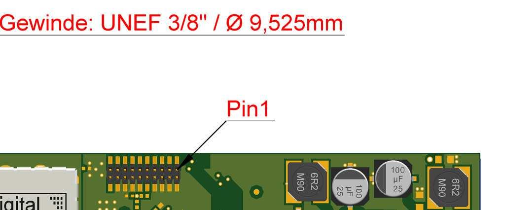
4 5. Cleaning The TV card does not require cleaning under normal operation. In the unlikely event that cleaning is required ensure all power connectors and mains cables are properly disconnected. The TV card has no serviceable parts. Protect it from contamination (see Safety Considerations above) and do not use solvent, caustic or gaseous cleaning agents. If necessary, the external connectors of the TV card can be cleaned with a soft, dry antistatic cloth. 6. Data Backup Always make a backup copy of your data on a suitable external storage medium (CD, floppy, Zip etc.) before and after updating. Claims for damages in respect of lost data and consequential losses arising from lost data will not be accepted. 7. Installation of DuoFlex S2 DVB Card (Please refer to the illustrations on the following pages) Read the safety instructions for your PC and those on previous pages carefully. Turn off the PC and all peripheral devices. Unplug the power cable and remove all other external cables. Unscrew and carefully remove the PC cover to gain access to the inside. Unscrew the blank slot bracket from a free PCIe slot and remove it. 2 slot brackets (full height & low profile) are enclosed in the package. Holding the DuoFlex S2 by its edges, carefully screw the appropriate slot bracket for your PC to the card. Again, holding the DuoFlex S2 by its edges, position it vertically over a free PCI/PCIe slot and locate the slot bracket in the PC chassis. Be careful not to damage any internal components. Screw the slot bracket of the DuoFlex S2 to the PC chassis. Connect a standard 4 pin floppy power connector (to power the LNB) to the connector at the rear of the DuoFlex S2. Plug the 20 pin flat ribbon cable to the connector of the DuoFlex S2 and to a Bridge or Cine TV card, as appropriate (see illustrations on next page). Replace the PC cover and reconnect all cables. Connect the coaxial antenna cable(s) to the corresponding antenna connector(s) of the DuoFlex S2 card. The installation of your new DuoFlex S2 card with its connections is now complete. Finally, connect the power cable to the PC and switch on the PC. Do not try to start the PC unless the PC cover is tightly refitted and secure Illustration DuoFlex S2 with connectors 20 pin extension connectors to Bridge or Cine TV card LNB-F antenna connectors Hole for mounting low profile / full height bracket 4 pin floppy power connector (for LNB power supply) Installation instructions 06/2011 Copyright Digital Devices GmbH page 4/23


 Unicable is a single cable distribution technology that enables")


5 Connection to a Cine S2 DVB-S2 card Connection to an Octopus LE Bridge Please note on the correct connection of the flat ribbon cable:- PIN 1 (red cable) of the DuoFlex S2 on the right and of the Bridges and Cine cards on the left. 8. Unicable Installation Single Cable solution via En50494/SCR (Single Cable Routing) Unicable is a single cable distribution technology that enables delivery of multiple, simultaneous DVB signals via a single coax antenna cable. Up to 8 tuners can be connected to a Unicable /SCR/CENELEC En50494 compliant LNB or Multiswitch. Both F connector ports of the DuoFlex S2 must be connected via a suitable 2-way splitter to feed the combined signal to each tuner from the antenna. The splitter must be suitable for Unicable to allow bi-directional passage of both RF and DC signals between the LNB and tuners. The assignment of the appropriate Unicable frequencies and channels is made via the DVBCineConfigTool (see Chapter 12). Installation instructions 06/2011 Copyright Digital Devices GmbH page 5/23
 and SRG - Mascom Easy TV with Sky S02 and ORF - SMIT Irdeto/Cryptoworks with ORF (2 tuners) - SMIT Viaccess with SRG (2 tuners) - Technicrypt CW with ORF (2 tuners) -")
. Carefully screw the appropriate bracket for your PC to the CI card.")

 and the CI card (red wire to bottom) Illustration:-")
6 9. Installation of a Common Interface (CI) Tested CAMs: - Mascom Alphacrypt Light with Sky S02 (Firmware 1.16/3.16) and SRG - Mascom Easy TV with Sky S02 and ORF - SMIT Irdeto/Cryptoworks with ORF (2 tuners) - SMIT Viaccess with SRG (2 tuners) - Technicrypt CW with ORF (2 tuners) - SCM Cryptoworks (1 tuner) For Mascom CAMs, the protection of minors (parental control) feature should be switched off for use when viewing Sky. 2 slot brackets are enclosed with the package (full height and low profile). Carefully screw the appropriate bracket for your PC to the CI card. Holding the CI card carefully by its edges, position it vertically over a free PCI/PCIe slot and locate the slot bracket in the PC chassis. Be careful not to damage any internal components. Screw the slot bracket to the PC chassis. Connect a standard 4 pin floppy power connector (to power the LNB) to the connector at the rear of the CI card. Connect the supplied 20 pin ribbon cable to the corresponding connectors of your Cine DVB card (red wire on left) and the CI card (red wire to bottom) Illustration:- Connection to a Cine S2 card. The CI can also be connected to a Bridge, as illustrated in Section 7. 4 pin floppy power connector Illustration:- CI module with 20 pin ribbon cable showing low profile and full height brackets Installation instructions 06/2011 Copyright Digital Devices GmbH page 6/23
 - Windows Vista (32/64 bit) - Windows 7 (32/64 bit) and the BDA driver for Mediaportal DVB Viewer.")


7 10. Driver Installation The TV card has now been installed in your PC in accordance with the previous sections and you have restarted the computer. Drivers are available for the following operating systems:- - Windows XP (32/64 bit) - Windows Vista (32/64 bit) - Windows 7 (32/64 bit) and the BDA driver for Mediaportal DVB Viewer. In Windows XP, you must log on with an administrator s account. Open your web browser and go to On the home page click on Downloads and when the page has opened download the appropriate drivers and save to a convenient location. (executable file: DigitalDevices DVB Driver X.msi ) Run the setup program by double clicking the file you just downloaded DigitalDevices DVB Driver X.msi. Follow the on-screen instructions. When the installation is complete, restart the computer. The Unicable feature is integrated in the driver, and can be configured via the DVBCineConfig tool. If your operating system is configured by default to accept only Microsoft approved (signed) programs and drivers, a warning message may appear:- Windows cannot verify the publisher of this driver software...". This is not an indication of a fault with the driver, but to the absence of Microsoft WHQL certification and can therefore be ignored by clicking the Next button or the option to, Install this driver software anyway When new drivers or programs are installed, existing data is overwritten or changed. You should accordingly create a backup copy before installation on your hard drive. Claims for damages in respect of lost data and consequential losses arising from lost data will not be accepted. Please ensure you follow the safety precautions for your PC (consult the PC manual). After a successful driver installation, four new devices will be identified by the operating system. Example of an installation under Windows 7 with a Common Interface (CI) connected:- Installation instructions 06/2011 Copyright Digital Devices GmbH page 7/23
. 11.")

.")

 / SCR Single cable solution")
8 In Windows 7 Device Manager, under Sound, video and game controllers, you will find 4 entries for Digital Devices (without a CI there will only be 3 entries). 11. DVB Cine Config Tool After the restart you can configure the TV card in Windows Media Center or an alternative software TV program. You will now find a folder called Digital Devices in the Windows Start Menu (Desktop -> Start -> All programs). You will find DVBCineConfig in the sub-folder DVB Devices :- This program allows you to configure the following:- Unicable Common Interface Transponder List for Windows Media Center Configuration of the C/T Tuner DVBCineConfig Main menu Single cable reception (Unicable Configuration) Common Interface Module Transponder List Media Center Configuration of C/T tuner (Unicable ) / SCR Single cable solution En Unicable / SCR En Operation Mode Selection Normal operation (without Unicable) Single cable reception, Unicable configuration EN Installation instructions 06/2011 Copyright Digital Devices GmbH page 8/23


 Assign the CI to one tuner only, or")


 Common Interface Module (CI) CAM Mainmenu The sub-menus provide")
9 Unicable reception Operation Mode LNB/Switch Selection Selection of the LNB / Multiswitch manufacturer Selection of the LNB or Multiswitch Unicable reception Operation Mode LNB/Switch Selection Selection of assignable slots Assignment of each tuner to a slot. Common Interface Module (CI) Example with an easy.tv module Common Interface Module (CI) Assign the CI to one tuner only, or if the CAM supports MTD Technology, multiple tuners can be assigned to this single CAM. The CAM Menu button provides access to the CAM configuration dialogue. (Please note that the CAM menu structure is dependent upon the particular CAM installed and menu details may differ slightly from the examples shown here) Common Interface Module (CI) CAM Mainmenu The sub-menus provide information regarding your Smart Card and its configuration. Installation instructions 06/2011 Copyright Digital Devices GmbH page 9/23
 CAM Mainmenu Parental Lock (child lock) Age-limit: OFF Age-limit on smartcard: not defined")

 CAM Mainmenu Module Options Language Select the desired operating language.")
10 Common Interface Module (CI) CAM Mainmenu Informations This menu provides data for your CAM module. Common Interface Module (CI) CAM Mainmenu Parental Lock (child lock) Age-limit: OFF Age-limit on smartcard: not defined Change personal identification number release current program back Common Interface Module (CI) CAM Mainmenu Module Options The module options are set here. Note: In MTD Mode the Parental lock must be disabled. In Media Center it is not possible to address a Parental lock PIN. Select Youth Protection in Media Center, if required. Common Interface Module (CI) CAM Mainmenu Module Options Language Select the desired operating language. Installation instructions 06/2011 Copyright Digital Devices GmbH page 10/23


11 Common Interface Module (CI) CAM Main menu Module Options AlphaCrypt application/ updates Optional software updates (auto search and install) for your CAM. Select the desired update option and enter the PID manually. Common Interface Module (CI) Confirm the settings for the CAM and CI modules and the assignment of slots for the tuners by hitting the Done button, and then restart the PC. Transponder List Transponder List Main Menu Option to load a pre-defined transponder list into Windows Media Center. Transponder List Main Menu Transponder list conversion An existing transponder list, which you may have created using, for example, TransEdit (DVB Viewer ), can be converted here. Installation instructions 06/2011 Copyright Digital Devices GmbH page 11/23


12 Transponder List Main Menu Transponder list selection Check the relevant tick-box for the transponder lists appropriate for your own broadcast reception. In this example, Astra 19.2 East and Atlantic Bird are selected. Confirm your entries with Save. Transponder List Main Menu Choosing a default setting One or more channel lists can be included. The channels in the channel list are ready-sorted. To learn how to create a pre-defined channel list, see the next section. Transponder List Main Menu Creation of a transponder list for Media Center By clicking the button indicated a transponder list will be created for Windows Media Center. Transponder List Main Menu Load the transponder list into Media Center By clicking on the Load button, the transponder list will be copied into Windows Media Center. The installation in Media Center is described in the following chapter. Configuration of C/T Tuner Configuration of the C/T Tuner is covered in the User Manual for the Cine C/T and DuoFlex C/T. Installation instructions 06/2011 Copyright Digital Devices GmbH page 12/23


13 12. Hardware Setup in Windows Media Center (MCE) When the transponder list has been loaded in Media Center, as described in Chapter 12, it now needs to be activated. The option for automatic download of media information for DVDs, movies and internet related services under Settings > General Options must be disabled. Please follow these steps:- Go to the Functions / Settings menu Click General Click Options for automatic downloads Installation instructions 06/2011 Copyright Digital Devices GmbH page 13/23


14 Disable the option to Receive CD cover, media information for DVDs and movies and internet services You can activate this option again after successful installation of the TV card. (Unless this option is disabled a required menu will not displayed when the TV card is being set up) Go back into the main Settings menu Now the TV card can be installed. Click TV in the menu Click on TV-Signal Installation instructions 06/2011 Copyright Digital Devices GmbH page 14/23


15 Click on Set up the TV-Signal Confirm selection of your region with Yes, use this region for the configuration of the TV services Or, choose a different region Input your Post Code Read the Terms of use and confirm with I agree or, I do not agree cancels setup Installation instructions 06/2011 Copyright Digital Devices GmbH page 15/23


 (by Digital Devices).")
16 NO must be selected here, otherwise the newly loaded transponder list will be overwritten. A message, You will receive no TV-Channel lists to download. Continue? will appear. Confirm with Yes The TV signals are verified. The detected TV signal will be displayed with a request for confirmation. Confirm with Yes, configure the TV signal with these results (2 tuners have been detected, indicating both tuners have a coaxial cable connection with sufficient signal strength) Alternatively, re-execute signal detection, Or, configure the signal manually If the channel list has been successful loaded, you will see, for example, Satellite: ASTRA 1H,1KR,1L,1M (19,2E) (by Digital Devices). Confirm the result with, Yes Installation instructions 06/2011 Copyright Digital Devices GmbH page 16/23


17 Click, Next These settings will be saved In the following menu, select the required EPG reception mode, either automatic or manual Setup is now complete. Confirm with, Finish The Pay TV channels must now be activated in Settings In the Settings menu select Guide Installation instructions 06/2011 Copyright Digital Devices GmbH page 17/23


18 Select Edit channels Activate the Pay TV channels by clicking in the relevant boxes After you have activated the channels and have mapped their locations, save the channel list and exit. Now start Live TV or the EPG. Once you have selected a Sky channel on a transponder, you can see the EPG data for the transponder and the Program Guide for the optional channels. Installation instructions 06/2011 Copyright Digital Devices GmbH page 18/23
19 13. Channel List Creation You have the ability to create pre-defined channel lists. Examples of pre-defined channel lists can be found in your Programs folder under Digital Devices \ DVB-Utils. These files are: PresetDE.csv PresetAT.csv PresetCH.csv PresetNL.csv PresetFR.csv PresetRadio.csv includes the standard channels in the region: Germany. includes the standard channels in the region: Germany Austria. includes the standard channels in the region: Switzerland. includes the standard channels in the region: Netherland. includes the standard channels in the region: France. includes the standard radio channels. PresetSkyGermany.csv includes the standard channels for SKY TV (Germany). These lists can be edited using a spreadsheet such as Excel, or in a text editor. To change the channel order, change its number value. Ensure where possible that no channel is entered more than once, as this could lead to problems later in Windows Media Center. After editing the file, it must be saved in UTF8 format. As an alternative to editing manually in Excel or in a text editor, please refer to the Digital Devices Knowledge Base online and search for a tool called "DD channel sorter", which provides a simpler means of sorting / rebuilding the channel lists. The remaining files in the directory, for example, "Astra192.csv" are not channel lists. These files contain frequency information and should not normally be changed. When the frequency of a channel is changed the channel data can be edited in these files. Installation instructions 06/2011 Copyright Digital Devices GmbH page 19/23
20 14. Troubleshooting If an error occurs run through the checklist below to find a solution. Check that the PC and all peripheral devices are powered on. Turn the computer off and re-check all cable connections. Do not swap cables attached to different devices indiscriminately, even if they appear to be identical. If you are sure that the power supply is operating properly, turn the computer back on. Many mistakes can be avoided through the regular use of the Chkdsk, ScanDisk and Disk Defragmenter programs. These programs promote efficient system performance. No TV Picture / No Radio Sound Check that the antenna cable(s) is connected to the correct connector(s). Is the signal from the antenna cable sufficiently strong or require boosting? Does your LNB have power? Consult the manual for the LNB. Is the floppy connector which powers the LNB via the TV card properly connected? Check that your PC meets the system requirements (refer to the packaging box cover). Are the DiSEqC settings properly configured for the TV card? Is a digital or universal LNB/LNC available? Try installing the TV card in a different PCIe slot. Unicable /CENELEC En50494: ensure Unicable has been properly configured using the DVBCineConfig tool. (Start -> All programs -> Digital Devices -> DVB Devices -> DVBCineConfig) No videotext Has the Teletext program started previously? Are there sufficient system resources? Hardware conflicts and system crashes Try using a different PCI Express slot Some motherboards do not recognise Digital Devices DVB cards in the PCI Express x16 slot. In such cases try using either a PCIe x1 or x4 slot. In the BIOS setup for your motherboard, disable C1E Support. In the BIOS setup, PCI Express overclocking must be set to 100 (not to auto ). For Intel Core i systems, the latest video & chipset drivers (version ) must be used (older versions can cause problems). AMD graphics cards can produce blocking in HD displays. Turn off DXVA (DirectX Video Acceleration) to resolve this problem Please contact your dealer if you continue to experience problems. More complex errors should be investigated and corrected by a specialist. Installation instructions 06/2011 Copyright Digital Devices GmbH page 20/23
21 15. Electromagnetic Measurement and Declaration of Conformity SGS-TUEV Saarland Forster GmbH EUT Information Description: EUT Name: ManufaC/Turer: Typ: S/N: HW Rev: DVBS2 Linux4Media GmbH Test Report 5V3 SW/FW Rev: Operating cond.: Tuner 2, DVB-SII Live Stream Operator: Dipl. -Ing. (FH) Sven Eric Weber Test Spec.: EN55013 Test Side: SAC 1 Supply: AC230V Comment: Mit Desktop PC EMI Auto Test Template: EN55013 Hardware Setup: EMI radiated\elec/tricfield Strength VULB Frequency Range: 30MHz - 1GHz Graphics Level Range: 0dBµV/m - 80dBµV/m Preview Measurements: Scan Test Template: Prescan Field Strength VULB oh Data ReduC/Tion: 1st Limit Line: EN EleC/Tric Field Strength 3 m QP Maximum Results: 25 Acceptance Offset: -15 db Maximization Measurements: Template for Single Meas.: Max Field Strength VULB oh Adjustment: Scan Template for Adjustment Measurements : Max Field Strength VULB oh Final Measurements: Template for Single Meas.: Final Field Strength VULB oh Subrange DeteC/Tors IF Bandwidth Meas. Time Receiver 30 MHz 1GHz Quasi Peak 120 khz 1 s ESBI Report Settings: Document Name: Institute: Create EleC/Tronic Report: PDF EMI Report SGS-TUEV Saarland Forster GmbH Page: 1 Time: 12:05:11 / Installation instructions 06/2011 Copyright Digital Devices GmbH page 21/23


22 16. Expansion options DuoFlex S2 (examples) All Digital Devices DVB components can be combined and inter-connected. A very wide variety of combinations can be achieved. In Section 7 above, two basic configurations have been illustrated, (1) with a bridge and (2) with a Cine S2. Illustrated below are further examples of a typical installation with a DuoFlex S2:- Combination examples: 1 Cine S2 + 2 DuoFlex S2 = 6 DVB-S2 tuners 1 Cine S2 + 1 DuoFlex S2 + 1 CI = 4 DVB-S2 + 1 CI MTD (Multi Transponder Decrypting): Decrypt 4 encrypted TV channels with only 1 CAM! View 1 encrypted program while recording up to 3 others. NB Not all CAMs support this feature. Compatible CAMs can be found on our website. 1 Cine C/T + 1 DuoFlex S2 + 1 CI = 2 DVB-S2 + 2 DVB-C/T + 1 CI 1 Octopus PCIe Bridge + 2 DuoFlex S2 + 1 DuoFlex C/T + 1 CI = 4 DVB-S2 + 1 DVB-C/T Tuner + 1 CI Microsoft is a trademark of the Microsoft group of companies Windows is a registered trademark of the Microsoft Corporation in the United States and other countries All other trademarks are property of their respective owners Installation instructions 06/2011 Copyright Digital Devices GmbH page 22/23


23
Single cable multiswich programmer PC102W
 Single cable multiswich programmer PC102W 1. Product description The PC102W - single cable multiswich programmer (in the text - programmer) is useful instrument while configuring and troubleshooting SAT
USERS GUIDE MCX-HTS. HDMI to 3G SDI Converter. Manual Number:
 USERS GUIDE MCX-HTS HDMI to 3G SDI Converter i Manual Number: 151226 SAFETY INSTRUCTIONS Please review the following safety precautions. If this is the first time using this model, then read this manual
Cat s Eye edta-164 HDTV Tuner Card
 Cat s Eye edta-164 HDTV Tuner Card Installation Guide Version 1.0 VBox Communications Ltd. www.vboxcomm.com Copyright 2006, VBox Communications Ltd. All rights reserved. No part of this publication may
USER MANUAL. 22" Class Slim HD Widescreen Monitor L215DS
 USER MANUAL 22" Class Slim HD Widescreen Monitor L215DS TABLE OF CONTENTS 1 Getting Started Package Includes Installation 2 Control Panel / Back Panel Control Panel Back Panel 3 On Screen Display 4 Technical
VDT-100 User Manual 1
 VDT-100 User Manual 1 Copyright Notice The use manual, including all its contents, is copyrighted by Videa Technology Inc.. All rights are reserved. Videa Technology Inc. reserves the right to improve
USERS GUIDE ASP-VTHS. VGA & Audio to HDMI Scaler Converter. Manual Number:
 USERS GUIDE ASP-VTHS VGA & Audio to HDMI Scaler Converter i Manual Number: 131120 User Guide SAFETY INSTRUCTIONS Please review the following safety precautions. If this is the first time using this model,
User Manual. SCR Multiswitch Ref. 9744SKY, 9746SKY, 9748SKY
 User Manual SCR Multiswitch Ref. 9744SKY, 9746SKY, 9748SKY No part of this manual may be copied, reproduced, transmitted, transcribed or translated into any language without permission. Unitron reserves
DVB-T USB SET-TOP BOX
 DVB-T USB SET-TOP BOX User Manual Version: 1.0 (February 2005) TRANSYSTEM INC. No.1-2 Li-Hsin Rd.I Science-Based Industrial Park, Hsinchu, Taiwan Tel:+886-3-5780393 Fax:+886-3-5784111 e-mail: sales@transystem.com.tw
HD-1603 Single Input MPEG-4 DVB-T HD Encoder/Modulator User Guide and Install Manual
 ZyCastR digi-mod HD Range digi-mod HD-1603 www.digi-modbyzycast.com HD-1603 Single Input MPEG-4 DVB-T HD Encoder/Modulator User Guide and Install Manual Table of Contents www.digi-modbyzycast.com Safety
PRO-ScalerHD2V HDMI to VGA & Audio Scaler Converter. User s Guide. Made in Taiwan
 PRO-ScalerHD2V HDMI to VGA & Audio Scaler Converter User s Guide Made in Taiwan Congratulations for owning a gofanco product. Our products aim to meet all your connectivity needs wherever you go. Have
SignalOn Series. L-Band Power Inserter Module INSTALLATION & OPERATION MANUAL. 1.2 GHz. D3.
 SignalOn Series D3.1/CCAP Compliant 1.2 GHz L-Band Power Inserter Module INSTALLATION & OPERATION MANUAL www.atxnetworks.com www.atxnetworks.com Although every effort has been taken to ensure the accuracy
TR6102HD HDTV/DVD/COMPONENT VIDEO TO RGBHV TRANSCODER USER S GUIDE
 MANUAL PART NUMBER: 400-0031-003 PRODUCT REVISION: 1 HDTV/DVD/COMPONENT VIDEO TO RGBHV TRANSCODER USER S GUIDE INTRODUCTION Thank you for your purchase of the Transcoder. We are certain that you will find
ASH - EOC-01. Ethernet Over Coax Adapter User Guide
 ASH - EOC-01 Ethernet Over Coax Adapter User Guide ASH - EOC-01 User s Guide 1 Table of Contents Warning and Safety Information 3 Product Overview 8 Package Contents and Accessories 8 Introduction 9 Indicators
AVerMedia DarkCrystal HD Capture SDK II C729. English. Quick Guide
 AVerMedia DarkCrystal HD Capture SDK II C729 English Quick Guide FCC NOTICE (Class B) This device complies with Part 15 of the FCC Rules. Operation is subject to the following two conditions: (1) this
DVB-S 100 Installation Manual
 DVB-S 100 Installation Manual Contents V2.0 Chapter 1 : DVB-S 100 PCI Card Hardware Installation...2 1.1 Package Contents...2 1.2 System Requirements...2 1.3 Hardware Installation...2 Chapter 2 : DVB-S
USER MANUAL. 27 Full HD Widescreen LED Monitor L27ADS
 USER MANUAL 27 Full HD Widescreen LED Monitor L27ADS TABLE OF CONTENTS 1 Getting Started 2 Control Panel/ Back Panel 3 On Screen Display 4 Technical Specs 5 Care & Maintenance 6 Troubleshooting 7 Safety
USER MANUAL. 27" 2K QHD LED Monitor L27HAS2K
 USER MANUAL 27" 2K QHD LED Monitor L27HAS2K TABLE OF CONTENTS 1 Getting Started 2 Control Panel/ Back Panel 3 On Screen Display 4 Technical Specs 5 Troubleshooting 6 Safety Info & FCC warning 1 GETTING
P XGA TFT Monitor. User s Manual
 P6151 15 XGA TFT Monitor User s Manual Disclaimers This manual has been carefully checked and believed to contain accurate information. Axiomtek Co., Ltd. assumes no responsibility for any infringements
USER MANUAL. 27 Full HD Widescreen LED Monitor L270E
 USER MANUAL 27 Full HD Widescreen LED Monitor L270E TABLE OF CONTENTS 1 Getting Started 2 Control Panel/ Back Panel 3 On Screen Display 4 Technical Specs 5 Care & Maintenance 6 Troubleshooting 7 Safety
Unicable II Programmer. IDLU-PROG01-OOOOO-OPP Item: Installation & User Guide
 Unicable II Programmer IDLU-PROG01-OOOOO-OPP Item: 5273 Installation & User Guide 1 2 Thank you for purchasing Inverto s advanced Unicable II programmer. Before installing and using the programmer, please
User Manual. dcss/dscr Multiswitch 9732
 User Manual dcss/dscr Multiswitch 9732 CONTENTS 1. INSTALLATION OF THE HARDWARE... 3 2. CONFIGURATION OF THE MODULE... 4 Installation Mode... 4 CSS Mode... 4 ONLY EN50494/SCR standard... 4 ONLY EN50607/dCSS
User s Manual HDMI Modulator ATSC 8VSB/QAM 65/256. Model No : HDM100
 User s Manual HDMI Modulator ATSC 8VSB/QAM 65/256 Model No : HDM100 Contents 1. Safety Instructions & Precautions. 1 2. Operation Guide.. 2 2-1. Connection Diagram. 2 2-2. Front Panel.... 3 2-3. Rear Panel.....
DVB-T Hybrid X8000T. PCI Card
 176149 DVB-T Hybrid X8000T PCI Card User Manual Ver: 1.0 Contents 1. Getting Started... 1 1.1 Introduction...1 1.2 Features...1 1.3 Package Contents...1 1.4 System Requirements...2 2. Input & Output Connections...
DISTRIBUTION AMPLIFIER
 MANUAL PART NUMBER: 400-0045-005 DA1907SX 1-IN, 2-OUT VGA/SVGA/XGA/UXGA DISTRIBUTION AMPLIFIER USER S GUIDE TABLE OF CONTENTS Page PRECAUTIONS / SAFETY WARNINGS... 2 GENERAL...2 GUIDELINES FOR RACK-MOUNTING...2
V/L V/H H/L H/H. Satellite - Input. Programmable Cascadable switch. with 32 User Bands with Terrestrial input & 1 Legacy port
 : 47-862MHz For default UB frequencies: Unicable II Multiswitch 32 User Bands with & 1 Legacy port Installation manual 1 2 Thank you for purchasing Inverto s advanced multiswitch and we are certain it
MyM Pro 3S/6S Installation guide
 MyM Pro 3S/6S Installation guide CONTENT 1. Introduction 2. Unpacking the unit 3. Connections and indications 4. IP settings 5. Menus and settings web ui 5.1 Overview menu 5.2 Input settings 5.3 Output
Digital Terrestrial Alignment & Installation Meter
 Digital Terrestrial Alignment & Installation Meter Instruction Booklet Version 3 - February 2005 www.horizonhge.com Thank you for choosing our latest and most innovative terrestrial meter. It has been
user manual Colosseum 8500D
 user manual Colosseum 8500D No part of this manual may be copied, reproduced, transmitted, transcribed or translated into any language without permission. Unitron reserves the right to change the specifications
ivw-fd122 Video Wall Controller MODEL: ivw-fd122 Video Wall Controller Supports 2 x 2 Video Wall Array User Manual Page i Rev. 1.
 MODEL: ivw-fd122 Video Wall Controller Supports 2 x 2 Video Wall Array User Manual Rev. 1.01 Page i Copyright COPYRIGHT NOTICE The information in this document is subject to change without prior notice
TVW750USBD ATSC Tuner Quick install manual
 Getting Started TVW750USBD ATSC Tuner Quick install manual The Diamond TVW750USBD ATSC Tuner is fully compatible for your Windows desktop PC or laptop. Important Notice: All channels are subject to coverage
Disclaimer of Product & Services The information offered in this instruction manual is intended as a guide only. At all times, Datavideo Technologies
 TC-100 Table of Contents FCC COMPLIANCE STATEMENT... III WARNINGS AND PRECAUTIONS... III WARRANTY... V STANDARD WARRANTY... V THREE YEAR WARRANTY... V DISPOSAL... VI INTRODUCTION... 1 FEATURES... 1 HOW
USER MANUAL. 28" 4K Ultra HD Monitor L28TN4K
 USER MANUAL 28" 4K Ultra HD Monitor L28TN4K TABLE OF CONTENTS 1 Getting Started 2 Control Panel/ Back Panel 3 On Screen Display 4 Technical Specs 5 Care & Maintenance 6 Troubleshooting 7 Safety Info &
Dish Diversity Switch
 www.travel-vision.com Dish Diversity Switch INSTALLATION & USER S MANUAL Version 3.1 October 2013 PREFACE The information in this Installation and User s Manual is subject to change in order to improve
USER MANUAL Full HD Widescreen LED Monitor L215ADS
 USER MANUAL 21.5 Full HD Widescreen LED Monitor L215ADS TABLE OF CONTENTS 1 Getting Started 2 Control Panel/ Back Panel 3 On Screen Display 4 Technical Specs 5 Care & Maintenance 6 Troubleshooting 7 Safety
USER MANUAL Full HD Widescreen LED Monitor L215IPS
 USER MANUAL 21.5 Full HD Widescreen LED Monitor L215IPS TABLE OF CONTENTS 1 Getting Started 2 Control Panel/ Back Panel 3 On Screen Display 4 Technical Specs 5 Care & Maintenance 6 Troubleshooting 7 Safety
PLL2210MW LED Monitor
 PLL2210MW LED Monitor USER'S GUIDE www.planar.com Content Operation Instructions...1 Safety Precautions...2 First Setup...3 Front View of the Product...4 Rear View of the Product...5 Quick Installation...6
O P E R A T I O N M A N U A L. RF-Reader. Stand-alone-Reader Leser 2plus with RS-232 interface
 O P E R A T I O N M A N U A L Version 01/05 RF-Reader Stand-alone-Reader Leser 2plus with RS-232 interface Important! Read by all means! To maintain the perfect shipping conditions and to ensure safe operation
DVB-T Box, USB Monheim/Germany Tel. +49 (0)9091/ Fax +49 (0)9091/ Hama GmbH & Co KG.
9091/ Fax +49 (0)9091/ Hama GmbH & Co KG.") www.hama.de Hama GmbH & Co KG Postfach 80 86651 Monheim/Germany Tel. +49 (0)9091/502-0 Fax +49 (0)9091/502-274 hama@hama.de www.hama.de 00062776-01.05 DVB-T Box, USB 2.0 00062776 L TV USB receiver User
www.hama.de Hama GmbH & Co KG Postfach 80 86651 Monheim/Germany Tel. +49 (0)9091/502-0 Fax +49 (0)9091/502-274 hama@hama.de www.hama.de 00062776-01.05 DVB-T Box, USB 2.0 00062776 L TV USB receiver User
PRO-ScalerV2HD VGA to HDMI & Audio Scaler Converter. User s Guide. Made in Taiwan
 VGA to HDMI & Audio Scaler Converter User s Guide Made in Taiwan Congratulations for owning a gofanco product. Our products aim to meet all your connectivity needs wherever you go. Have fun with our products!
4, 8, 16 Port VGA/ Audio Extender / Splitter With Local Output with SPDIF Model #: VGA-C5SP-8
 4, 8, 16 Port VGA/ Audio Extender / Splitter With Local Output with SPDIF Model #: VGA-C5SP-8 2010 Avenview Inc. All rights reserved. The contents of this document are provided in connection with Avenview
SAT IF distribution system
 7. Technical specifications Type cs43 RF input frequency range pr. 50-350 MHz inputs number 4 level pr. 55...88 dbµv 60...93 dbµv symbol rate 3 45 Ms/s return loss/impedance > 0 db/75 Ω LNB powering/control
VGA / Audio Extender Single CAT5 / CAT6 with RGB Delay Control & EQ
 VGA / Audio Extender Single CAT5 / CAT6 with RGB Delay Control & EQ Model #: VGA-C5A-SET 2010 Avenview Inc. All rights reserved. The contents of this document are provided in connection with Avenview Inc.
AVE HOME FAGOR CVBS TO DVB-T ENCODER MODULATOR. Fagor Electr6nica
 AVE HOME CVBS TO DVB-T ENCODER MODULATOR FAGOR Fagor Electr6nica TABLE OF CONTENTS 1. SPECIFICATIONS... 12 1.1 Product Overview... 12 1.2 Appearance and Description... 12 1.3 Diagram... 13 1.4 Characteristics...
Table of Contents. 1. Safety Use. 2. General Description. 3. Connection Diagram. 4. Operations and Management. 4.1 Display Status. 4.
 DTM-HD01 Thank you for buying this encoder modulator. Please read this manual carefully to install, use and maintain the encoder modulator in the best conditions of performance. Keep this manual for future
Model#: IN-MDRI3MF. Hardware User Manual. 3MP Indoor Mini Dome with Basic WDR, Fixed lens. (PoE) Ver. 2013/02/04
 Ver. 2013/02/04") Model#: IN-MDRI3MF 3MP Indoor Mini Dome with Basic WDR, Fixed lens Hardware User Manual (PoE) Ver. 2013/02/04 Table of Contents 0. Precautions 3 1. Introduction 4 Package Contents... 4 Features and Benefits...
Model#: IN-MDRI3MF 3MP Indoor Mini Dome with Basic WDR, Fixed lens Hardware User Manual (PoE) Ver. 2013/02/04 Table of Contents 0. Precautions 3 1. Introduction 4 Package Contents... 4 Features and Benefits...
User Manual rev: Made in Taiwan
 CV-500S HDMI to Component/CVBS & Audio Scaler Converter User Manual rev: 131218 Made in Taiwan The CV-500S HDMI to Component/CVBS & Audio Scaler Converter has been tested for conformance to safety regulations
Satellite B or D. Satellite Inputs (LNB Trunk)
") Power Diagnosis V/L Satellite A C V/H H/L Satellite Inputs (LNB Trunk) Satellite B D 2 x Wideband LNBs (SAT A/B or C/D) Universal Quattro LNB (SAT A/B/C/D) H/H Terrestrial input On DC in 19V 3.5A max.
Power Diagnosis V/L Satellite A C V/H H/L Satellite Inputs (LNB Trunk) Satellite B D 2 x Wideband LNBs (SAT A/B or C/D) Universal Quattro LNB (SAT A/B/C/D) H/H Terrestrial input On DC in 19V 3.5A max.
Quick Installation Guide
 Digital TV USB 2.0 Dongle VG0002A Quick Installation Guide Table of Contents 1.0 Safety Instructions 2.0 Introduction 3.0 Installation 4.0 Total Media Software 5.0 CE Declaration 1.0 Safety Instruction
Reflecta Super 8 Scanner. User Manual
 Reflecta Super 8 Scanner User Manual 1 FEDERAL COMMUNICATIONS COMMISSION (FCC) STATEMENT This Equipment has been tested and found to comply with the limits for a class B digital device, pursuant to Part
MyM-3S Micro Master. Installation Guide. English. design for TV
 MyM-3S Micro Master Installation Guide design for TV 1 CONTENT 1. Introduction 2. Unpacking the unit 3. Connections and indications 4. IP settings 5. Menus and settings 5.1 Overview menu 5.2 Input settings
LINK EXT40-4KECO. 4K 40m HDMI Extender. User Manual. Version: V1.0.1
 LINK EXT40-4KECO 4K 40m HDMI Extender User Manual Version: V1.0.1 Important Safety Instructions 1. Do not expose this apparatus to rain, moisture, dripping or splashing and that no objects filled with
OSD. EXECUTIVE / MiniDome USERS MANUAL. USING THE MOTOSAT DISH POINTING SYSTEM EXECUTIVE / MiniDome OSD
 EXECUTIVE / MiniDome OSD USERS MANUAL USING THE MOTOSAT DISH POINTING SYSTEM EXECUTIVE / MiniDome OSD MotoSAT Corporation Created April 22, 2003 1-800-247-7486 CONGRATULATIONS! on your purchase of your
Package Contents Connections and Controls... 5 Front of the active Subwoofer... 5 Rear of the active Subwoofer... 6
 Table of Contents: Safety and Service... 2 Operational Safety... 2 Location... 2 Ambient Temperature... 3 Electromagnetic Compliance... 3 Service... 4 Cleaning... 4 Disposal... 4 Package Contents... 4
USER MANUAL Full HD Widescreen LED Monitor L236VA
 USER MANUAL 23.6 Full HD Widescreen LED Monitor L236VA TABLE OF CONTENTS 1 Getting Started 2 Control Panel/ Back Panel 3 On Screen Display 4 Technical Specs 5 Care & Maintenance 6 Troubleshooting 7 Safety
Owner s Manual. Sat-Meter MSK 15. Order No.:
 Owner s Manual Sat-Meter MSK 15 Order No.: 217 100 13 Thank you for choosing our latest and most innovative satellite meter. It has been designed and manufactured to a very high standard and offers a UNIQUE
DM-1CH SD DVB-T MODULATOR INSTRUCTION MANUAL
 DM-1CH SD DVB-T MODULATOR INSTRUCTION MANUAL 2. Caution Statements and Table of Contents Table of Contents 2. Caution Statements and Table of contents 3. Important Safety Instructions 4. Important Safety
TSM 1000 HD-C TSM 1000 HD-CF
 TSM 1000 HD-C TSM 1000 HD-CF User Manual MADE IN GERMANY 0901743 V1 Table of contents Page 1. Hazard and safety information 3 2. General 5 3. Description 5 4. Scope of supply 5 5. Input circuit 5 6. Assembly
TBS6909 User Guide. In order to use this item correctly, please read this user manual carefully at the beginning.
 TBS6909 User Guide Dear Customers, Thank you so much for using TBS products. TBS6909 is a PCI Express TV tuner card that supports multiple digital TV standards, including DVB-S2/S, which makes a switchover
DVB-LR10. Compatible with Land Rover touch-screen navigation systems version 2
 dvblogic DVB-T Tuner Compatible with Land Rover touch-screen navigation systems version 2 Product features full plug and play vehicle-specific dual DVB-T Tuner with two active DVB-T glass-mount antennas
ivw-fd133 Video Wall Controller MODEL: ivw-fd133 Video Wall Controller Supports 3 x 3 and 2 x 2 Video Wall Array User Manual Page i Rev. 1.
 MODEL: ivw-fd133 Video Wall Controller Supports 3 x 3 and 2 x 2 Video Wall Array User Manual Rev. 1.01 Page i Copyright COPYRIGHT NOTICE The information in this document is subject to change without prior
TracVision R6DX Installation Guide
 TracVision R6DX Installation Guide These instructions explain how to install the TracVision R6DX satellite TV antenna system on an RV or motor coach. Complete instructions on how to use the system are
User Guide. Single-Link DVI Active Cable Extender. DVI-7171c
 User Guide Single-Link DVI Active Cable Extender DVI-7171c TABLE OF CONTENTS SECTION PAGE PRODUCT SAFETY...1 PRODUCT LIABILITY...1 1.0 INTRODUCTION...2 2.0 SPECIFICATIONS...3 3.0 PACKAGE CONTENTS...4 4.0
17 19 PROFESSIONAL LCD COLOUR MONITOR ART
 17 19 PROFESSIONAL LCD COLOUR MONITOR ART. 41657-41659 Via Don Arrigoni, 5 24020 Rovetta S. Lorenzo (Bergamo) http://www.comelit.eu e-mail:export.department@comelit.it WARNING: TO REDUCE THE RISK OF FIRE
Be sure to run the vehicle engine while using this unit to avoid battery exhaustion.
 CAUTION: TO REDUCE THE RISK OF ELECTRIC SHOCK DO NOT REMOVE COVER (OR BACK) NO USER-SERVICEABLE PARTS INSIDE REFER SERVICING TO QUALIFIED SERVICE PERSONNE; Please Read all of these instructions regarding
Kramer Electronics, Ltd. USER MANUAL. Model: VM Video Component Distributor
 Kramer Electronics, Ltd. USER MANUAL Model: VM-1045 Video Component Distributor Contents Contents 1 Introduction 1 2 Getting Started 1 2.1 Quick Start 1 3 Overview 3 4 Your VM-1045 Video Component Distributor
LTC 113x & LTC123x FlexiDome Series Fixed Dome Cameras
 LTC 113x & LTC123x FlexiDome Series Fixed Dome Cameras Eng Installation Instructions F D E NL I IMPORTANT SAFEGUARDS 1. Read Instructions All the safety and operating instructions should be read before
User Manual. UNIVERSE Ref. 8600
 User Manual UNIVERSE Ref. 8600 No part of this manual may be copied, reproduced, transmitted, transcribed or translated into any language without permission. Unitron reserves the right to change the specifications
User Manual. HDMI Modulator Ref & SW Release
 User Manual HDMI Modulator Ref. 8201 & 8202 SW 1.1.1.Release No part of this manual may be copied, reproduced, transmitted, transcribed or translated into any language without permission. Unitron reserves
User Manual TL-2X1-HDVC 2x1 HDMI & VGA Switcher with Control All Rights Reserved Version: TL-2X1-HDVC_160630
 User Manual TL-2X1-HDVC 2x1 HDMI & VGA Switcher with Control All Rights Reserved Version: TL-2X1-HDVC_160630 Preface Read this user manual carefully before using this product. Pictures shown in this manual
Model#: IN-DI2MIRF 2MP Indoor Dome with True Day/Night, IR, Basic WDR, Fixed lens
 Model#: IN-DI2MIRF 2MP Indoor Dome with True Day/Night, IR, Basic WDR, Fixed lens Hardware User Manual (PoE) Ver.2013/01/17 Table of Contents 0. Precautions 3 1. Introduction 4 Package Contents...4 Features
UFG-10 Family USER MANUAL. Frame Grabbers. Windows 8 Windows 7 Windows XP
 UFG-10 Family Frame Grabbers USER MANUAL Windows 8 Windows 7 Windows XP About this Manual Copyright This manual, Copyright 2014 Unigraf Oy. All rights reserved Reproduction of this manual in whole or in
VGA, Audio & RS232 Extender SET over Single CAT5 with RGB Delay Control & IR Pass Through
 VGA, Audio & RS232 Extender SET over Single CAT5 with RGB Delay Control & IR Pass Through Model #: VGA-C5ARS-SET 2010 Avenview Inc. All rights reserved. The contents of this document are provided in connection
Outdoor & Indoor Full Color LED Display Screen. Installation Manual
 SHENZHEN VISULAL LUMEN CO.,LTD. Outdoor & Indoor Full Color LED Display Screen Installation Manual Thank you for your selected Visuallumen's outdoor & Indoor Full Color LED Display. For proper operation,
PL2410W LCD Monitor USER'S GUIDE.
 PL2410W LCD Monitor USER'S GUIDE www.planar.com Content Operation Instructions...1 Safety Precautions...2 First Setup...3 Front View of the Product...4 Rear View of the Product...5 Quick Installation...6
VGA & Audio Receiver SET over Single CAT5 with RGB Delay Control
 VGA & Audio Receiver SET over Single CAT5 with RGB Delay Control Model #: VGA-C5A-R 2010 Avenview Inc. All rights reserved. The contents of this document are provided in connection with Avenview Inc. (
User Manual. dcss/dscr Multiswitch 9733PL 9734PL
 User Manual dcss/dscr Multiswitch 9733PL 9734PL CONTENTS 1. INSTALLATION OF THE HARDWARE... 3 1.1. Quattro LNB... 3 1.2. Wideband LNB s... 4 2. CONFIGURATION OF THE MODULE... 5 2.1. Input : Quattro versus
USER MANUAL DUX-TX DUX-RX HDMI EXTENDER
 USER MANUAL DUX-TX DUX-RX HDMI EXTENDER Table of Contents Important Safety Instructions...03 Introduction...04 Features...04 Packing List...05 Specifications...06 DUX-TX Transmitter...06 DUX-RX Receiver...07
MOI-V Linux dvblast tvheadend VDR Operating Instructions
 MOI-V Linux dvblast tvheadend VDR Operating Instructions Dear Customers, Thank you very much for choosing TBS products. The professional IPTV streamer MOI-V supports up to 6 built-in TV tuner PCI-e cards
CAUTION RISK OF ELECTRIC SHOCK NO NOT OPEN
 Evolution Digital HD Set-Top Box Important Safety Instructions 1. Read these instructions. 2. Keep these instructions. 3. Heed all warnings. 4. Follow all instructions. 5. Do not use this apparatus near
INSTALLATION AND OPERATION INSTRUCTIONS EVOLUTION VIDEO DISTRIBUTION SYSTEM
 INSTALLATION AND OPERATION INSTRUCTIONS EVOLUTION VIDEO DISTRIBUTION SYSTEM ATTENTION: READ THE ENTIRE INSTRUCTION SHEET BEFORE STARTING THE INSTALLATION PROCESS. WARNING! Do not begin to install your
HDMI 5x1 Switch B-240-HDSWTCH-5X1 INSTALLATION MANUAL
 HDMI 5x1 Switch B-240-HDSWTCH-5X1 INSTALLATION MANUAL IMPORTANT SAFETY INSTRUCTIONS To reduce the risk of fire or electric shock, read and follow all instructions and warnings in this manual. Keep this
Installation Note. Agilent 89441A Option AYC Installation Kit
 Installation Note Agilent 89441A Option AYC Installation Kit Part Number: 89441-90074 Printed in USA February 2002 Notice. The information contained in this document is subject to change without notice.
VGA / Audio Extender Single CAT5 / CAT6 with RGB Delay Control & EQ
 AV Connectivity, Distribution And Beyond... VIDEO WALLS VIDEO PROCESSORS VIDEO MATRIX SWITCHES EXTENDERS SPLITTERS WIRELESS CABLES & ACCESSORIES VGA / Audio Extender Single CAT5 / CAT6 with RGB Delay Control
OWNER'S MANUAL MODEL: DTV-2000 STANDBY/ON
 OWNER'S MANUAL MODEL: DTV-2000 STANDBY/ON CH+ CH- TABLE OF CONTENTS SAFETY PRECAUTIONS IMPORTANT SAFETY INSTRUCTIONS and FEATURES ACCESSORIES and LOADING BATTERIES REMOTE CONTROL UNIT FRONT PANEL and REAR
BY-HPE11KTA. Operating Instructions. Coaxial - LAN Converter with PoE function. Indoor Use Only. Model No. Attached Installation Guide
 Operating Instructions Coaxial - LAN Converter with PoE function Model No. Indoor Use Only BY-HPE11KTA Attached Installation Guide Before attempting to connect or operate this product, please read these
Ambient Temperature...3 Electromagnetic Compliance...3
 TABLE OF CONTENTS: SAFETY AND SERVICE... 2 Operational Safety... 2 Location... 2 Ambient Temperature...3 Electromagnetic Compliance...3 Service... 3 Cleaning... 3 Package Contents... 4 Specifications...
MaxView Cinema Kit Quick Install Guide
 SYSTEM SETUP The MaxView will work at any of the following display settings: INSTALLATION MaxView Cinema Kit Quick Install Guide Step 1 - Turn off your computer. Disconnect your monitor s VGA cable from
PXL2760MW LED LCD Monitor
 PXL2760MW LED LCD Monitor USER'S GUIDE www.planar.com Content Operation Instructions...1 Safety Precautions...2 Package Overview...3 First Setup...4 Front View of the Product...5 Rear View of the Product...6
DMOD1200MS. HDMI Modulator. User Manual PLEASE READ THE MANUAL COMPLETELY BEFORE USE V.17.09
 DMOD1200MS HDMI Modulator User Manual PLEASE READ THE MANUAL COMPLETELY BEFORE USE V.17.09 CONTENTS 1. INTRODUCTION 1.1. Product Description 1.2. Package Contents 1.3. Hardware Installation 1.4. Safety
DT1-LR10. Compatible with Land Rover touch-screen navigation systems version 2
 dvblogic DVB-T Tuner Compatible with Land Rover touch-screen navigation systems version 2 Product features Full plug and play vehicle-specific dual DVB-T Tuner + USB-AV-Player DVB-T-Tuner MPEG4 compatible
LINK-MI LM-WHD05B. Wireless HDMI AV Transmission System. User Manual
 LINK-MI LM-WHD05B Wireless HDMI AV Transmission System User Manual Table of Contents 1.Important Information... 3 1.1 Safety Precautions... 3 1.2 Declaration of Conformity... 4 1.3 Trademark Information...
1x4, 1x8, 1x12, 1x16 VGA Extender / Splitter over Single CAT5
 1x4, 1x8, 1x12, 1x16 VGA Extender / Splitter over Single CAT5 User s Guide Models VGA-C5-SP-4 VGA-C5-SP-8 VGA-C5-SP-12 VGA-C5-SP-16 2009 Avenview Inc. All rights reserved. The contents of this document
User Manual TL-2X1-HDV 2x1 HDMI & VGA Switcher All Rights Reserved Version: TL-2X1-HDV_160630
 User Manual TL-2X1-HDV 2x1 HDMI & VGA Switcher All Rights Reserved Version: TL-2X1-HDV_160630 Preface Read this user manual carefully before using this product. Pictures shown in this manual are for reference
VGA & RS232 Extender SET over Single CAT5 with RGB Delay Control
 VGA & RS232 Extender SET over Single CAT5 with RGB Delay Control Model #: VGA-C5RS-SET 2010 Avenview Inc. All rights reserved. The contents of this document are provided in connection with Avenview Inc.
Long Range Ethernet Extender
 CopperLink Model 2160 Series Long Range Ethernet Extender Quick Start Guide Part Number: 07M2160-QS, Rev. B Revised: February 24, 2012 Sales Office: +1 (301) 975-1000 Technical Support: +1 (301) 975-1007
DT1-LR. for Landrover touch-screen navigation systems version 1
 dvblogic DVB-T Tuner for Landrover touch-screen navigation systems version 1 Product features Full plug and play vehicle-specific dual DVB-T Tuner + USB-AV-Player DVB-T-Tuner MPEG4 compatible (HD) USB-AV-Player
Manual for TV software. TT-Viewer version Figure: TT-budget S2-3200
 Manual for TV software TT-Viewer version 2.7.0 Figure: TT-budget S2-3200 Index Manual TT-Viewer 3 1. Starting TT-Viewer software 3 2. General settings 5 3. Assignment of hardware 6 3.1 Unicable 7 4. Renderer
HD-1600 Single Input MPEG-4 DVB-T HD Encoder/Modulator User Guide and Install Manual
 digi-mod HD Range digi-mod HD-1600 www.resi-linx.com HD-1600 Single Input MPEG-4 DVB-T HD Encoder/Modulator User Guide and Install Manual Table of Contents Safety Precautions 2 Package Contents 2 Product
MyM Pro T2 Installation guide
 MyM Pro T2 Installation guide CONTENT 1. Introduction 2. Unpacking the unit 3. Connections and indications 4. IP settings 5. Menus and settings web ui 5.1 Overview menu 5.2 Input settings 5.3 Output settings
Operating Instructions
 Operating Instructions SDI Input board Model No. AV-HS04M1 РУССКИЙ FRANÇAIS DEUTSCH ENGLISH ESPAÑOL ITALIANO Before operating this product, please read the instructions carefully and save this manual for