Microphone CONTROLS AND INDICATORS Front Panel Rear Panel Display... 13
|
|
|
- Merilyn Hampton
- 5 years ago
- Views:
Transcription
1
2 TABLE OF CONTENTS WELCOME TO THE WORLD OF MIDLAND RADIO FEATURES FCC NOTICE Exposure To Radio Frequency Energy / Licensing INSTALLING YOUR RADIO Preparation for Installation Mobile Installation DC POWER CABLE CONNECTION Mobile Operation Fixed Station Operation Replacing Fuses INSTALLING THE ANTENNA ACCESSORY CONNECTIONS External Speaker Microphone CONTROLS AND INDICATORS Front Panel Rear Panel Display Microphone OPERATING YOUR RADIO VFO or Channel Mode BASIC OPERATIONS Switching the power On/Off Adjusting the Volume Adjusting Frequency Adjusting the Channel Receiving Transmitting Switch between Main Channel and Sub-Channel Switch between VFO and Channel Mode Channel Edit Channel Delete CTCSS/DCS Encode and Decode Setup CTCSS Scan DCS Scan Frequency/Channel Scan Scan Skip Squelch off/squelch off Momentarily Keypad Lockout Transmit DTMF/5 Tone Signaling Transmit Tone Burst Frequency Transmit DTMF by Microphone Keypad FUNCTION MENU Beep Frequency Step Size Setup Display Mode Setup page 2
3 FUNCTION MENU (Continued) Squelch Level Setup Volume Level Setting Setting a Password Scan Dwell Time Setup Scan Pause Time Setup AOP (Automatic Power On) Setup Dual Watch Setup Backlight Brightness Setup TOT (Time Out Timer) APO (Automatic Power Off) Pilot Frequency DIR (LCD Display Direction) Setup Microphone Speaker RTDF (RX/TX Dissimilar Frequency) Setup Reset to the Factory Default Settings CHANNEL MENU RCDT (CTCSS/DCS Decode) Setup CTCSS/DCS Encode Setup High/Mid/Low Power Selection TENC (5 Tone Encode) Setup T-DEC (Add Optional Signaling) Signaling Combination Setup Bandwidth Selection Frequency Reverse Talk Around Offset Frequency and Direction Setup Editing Channel Name Busy Channel Lockout Transmit (TX) Off OWNID (Self ID Inquiry) Main Unit Keypad Menu Setup H-DIM Microphone Keypad Backlight Setup Micrphone Keypad Backlight Brightness Setup H-PA / H-PD Micrphone Self-Define Keypad Setup DTMF SETTINGS DTMF Encoding Group Setup DTMF Encoding Transmitting Time PROGRAMMING SOFTWARE Installing the USB Programming Software MAINTENANCE Factory Default Settings TROUBLESHOOTING SPECIFICATIONS CTCSS TONE FREQUENCY CHART (HZ) DCS CODES FREQUENCY CHART FCC WARNINGS AND STATEMENTS LIMITED WARRANTY (United States and Canada) For Product Purchased in the USA: page 3
4 WELCOME TO THE WORLD OF MIDLAND RADIO Congratulations on your purchase of a high quality product.your DBR2500 Dual Band Amatuer radio represents state-of-the-art engineering. The circuitry is all solid-state and mounted on a rugged printed circuit board. Your DBR2500 radio is designed for reliable and trouble-free performance. FEATURES degree rotatable TFT LCD display - Dual band UHF/VHF radio - Full alloy body for heat radiation - VFO mode and channel mode for different operation requirement - Separate single channel band width: Wide 25K, Middle band 20K, Narrow band 12.5K programmable memory channels - Separate CTCSS, DCS, DTMF, and 5 Tone setting for each single channel - Channel scan - Voltage level protection - LCD brightless control - Automatic power on function - Main unit and microphone key lock function - 5Tone signaling for data transfer, alarm, all call, ANI, remote kill, and remote wake - DTMF-ANI or 5Tone-ANI for automatic call recognition FCC NOTICE This equipment has been tested and found to comply with the limits for a Class B digital device, pursuant to part 15 of the FCC Rules. These limits are designed to provide reasonable protection against harmful interference in a residential installation. This equipment generates, uses and can radiate radio frequency energy and, if not installed and used in accordance with the instructions, may cause harmful interference to radio communications. However, there is no guarantee that interference will not occur in a particular installation. IMPORTANT! MIDLAND RADIO CORPORATION makes no warranty or claim regarding any modification to your DBR2500 not fully authorized by MIDLAND RADIO CORPORATION, nor any change in operability, performance, or regulatory compliance arising therefrom. You are solely responsible for operating your DBR2500 in accordance with the law. page 4
5 FCC NOTICE (Continued) If this equipment does cause harmful interference to radio or television reception, which can be determined by turning the equipment off and on, the user is encouraged to try to correct the interference by one or more of the following measures: Reorient or relocate the receiving antenna Increase the separation between the equipment and receiver Connect the equipment into an outlet on a circuit different from that to which the receiver is connected Consult the dealer or an experienced radio/tv technician for help IMPORTANT NOTICE, FCC LICENSE REQUIRED The DBR2500 operates within Amateur (HAM) frequencies which require an FCC (Federal Communications Commission) license. You must be licensed prior transmitting on this radio. Serious penalties could result from unlicensed use of HAM channels, in violation of FCC rules, as stipulated in the Communications Act s Sections 501 and 502 (amended). You will be issued a call sign by the FCC which should be used for station identification when operating the radio on Amatuer (HAM) channels. You should also cooperate by engaging in permissible transmissions only, avoiding channel interference with other HAM users, and being prudent with the length of your transmission time. To obtain a license or ask questions about the application, contact the FCC at CALL FCC or go to the FCC s website: and request form 605. Exposure To Radio Frequency Energy Your Midland radio is designed to comply with the following national and international standards and guidelines regarding exposure of human beings to radio frequency electromagnetic energy. United States Federal Communications Commission, Code of Federal Regulations: 47 CFR part 2 sub-part J American National Standards Institute (ANSI)/Institute of Electrical & Electronics Engineers (IEEE) C Institute of Electrical and Electronics Engineers (IEEE) C Edition National Council on Radiation Protection and Measurements (NCRP) of the United States, Report 86, 1986 International Commission on Non-lonizing Radiation Protection (ICNIRP) 1998 To control your exposure and ensure compliance with the general population or uncontrolled environment exposure limits, transmit no more than 50% of the time. The radio generates measurable RF energy exposure only when transmitting. The consumer must maintain a minimum safe separation distance of 23.6 inches (60 cm) from the antenna when transmitting. page 5
6 INSTALLING YOUR RADIO Preparation for Installation This transceiver may be installed in any 12-volt negative ground-system car or truck. Most current U.S. and foreign vehicles use a negative system, but some older models and some newer large trucks may have a positive ground. Check the requirements for your vehicle before you begin installation. Generally, you have a negative-ground system if the negative ( - ) battery terminal is connected to the engine block. Contact your dealer in the event you are unable to determine your vehicle s polarity system. Mobile Installation To install the tranceiver, select a safe, convenient location inside your vehicle that minimizes danger to your passengers and yourself while the vehicle is in motion. Consider installing the unit at an appropriate position so that knees or legs will not strike it during sudden braking of your vehicle. Try to select a well ventilated location that is shielded from direct sunlight. Also take into consideration the routing and length of the lead wires and cables to the power source, and antenna. 1. Install the Mounting bracket in the vehicle using the supplied selftapping screws (2pcs) and flat washers (2pcs). Car body Washer (M5) Tapping screw (M5x20mm) Mounting bracket 2. Position the tranceiver, then insert and tighten the supplied hexagon screws. -Double check that all screws are tightened to prevent vehicle vibration from loosening the bracket or DBR2500. page 6
7 DC POWER CABLE CONNECTION Locate the power input connector as close to the DBR2500 as possible. Mobile Operation The vehicle battery must have a nominal rating of 12V. Never connect the tranceiver to a 24V battery. Be sure to use a 12V battery that has sufficient current capacity. If the current to the tranceiver is insufficient, the display may darken during transmission, or transmitting power may be dramatically reduced. 1. Route the DC power cable supplied with the radio directly to the vehicle s battery terminals using the shortest path from the DBR We recommend that you do not use the cigarette lighter socket, as some cigarette lighter sockets introduce an unacceptable voltage drop. - The entire length of the cable must be insulated so that it is protected from heat, moisture, and engine secondary (high voltage) ignition system and cables. 2. After installing the DC power cable, to avoid the risk of damage, please use heat-resistant tape to tie together the DC power cable with the fuse box. Be sure to reinforce the entire power cable with heat resistant tape. 3. In order to avoid the risk of a short circuit, please disconnect the connection with the negative (-) battery terminal, then connect to the radio. 4.Confirm the correct polarity of the connections, then attach the power cable to the battery terminals; red connects to the positive (+) terminal and black connects to the negative (-) terminal. - Use the full length of the cable without cutting off excess even if the cable is longer than required. In particular, never remove the fuse holders from the cable. Red Black 5. Reconnect any wiring removed from the negative terminal. 6. Connect the DC power cable to the DBR2500 s power supply connector - Press the connectors firmly together until the locking tab clicks. page 7
8 Fixed Station Operation In order to use this DBR2500 for fixed station operation, you will need a separate 13.8V DC power supply (not included). The recommended current capacity of your power supply is 12A 1.Connect the DC power cable to the regulated DC power supply and ensure that the polarities are correct. (Red: positive, Black: negative) - Do not directly connect the DBR2500 to an AC outlet - Use the supplied DC power cable to connect the DBR2500 to a regulated power supply - Do not substitute a cable with smaller gauge wires 2.Connect the DBR2500 s DC power connector to the connector on the DC power cable. - Press the connectors firmly together until the locking tab clicks. Before connecting the DC power to the DBR2500, be sure to switch the transeiver and the DC power supply to OFF. Do not plug the DC power supply into an AC outlet until you make all connections. Replacing Fuses If a fuse blows, determine the cause, then correct the problem. After the problem is resolved, replace the fuse. If newly installed fuses continue to blow, disconnect the power cable and contact Midland Radio Corporation for assistance. page 8
9 Fuse Location Transceiver Supplied Accessory DC power cable Fuse Current Rating 10A 10A Only use fuses of the specified type and rating, failure to do so could cause damage to the DBR2500. If you use the transeiver for a long period of time when the vehicle battery is not fully charged or when the engine is OFF, the battery may discharge, and may not have sufficient power to start the vehicle. Avoid using the transceiver in these conditions. INSTALLING THE ANTENNA (Sold Separately) Before operating, install an efficient, well-tuned antenna. The success of your radio will depend largely on the type of antenna and its correct installation. Use a 50Ω impedance antenna and low-loss coaxial feed-line that has a characteristic impedance of 50Ω, to match the DBR2500 input impedance. Coupling the antenna to the DBR2500 via feed-lines having an impedance other than 50Ω reduces the efficiency of the antenna system and can cause interference to nearby broadcast television receivers, radio receivers, and other electronic equipment. Transmitting without first connecting an antenna or other matched load may damage the DBR2500. Always connect the antenna to the DBR2500 prior to transmitting. All fixed stations should be equipped with a lightning arrester to reduce the risk of fire, electrical shock, and transceiver damage. Specific installation requirements vary between vehicles. Use the following guidelines to install the antenna. *Where you locate your antenna does make a difference.* Some general rules for antenna location that can aid radio performance: 1. Metal surfaces covered by fiberglass or vinyl may affect radio range. Avoid these locations. 2. Mount the antenna as high on the vehicle as possible. The higher the better. 3. If possible, mount the antenna in the center of whatever surface you choose. 4. Be sure the mounting location is clean and dry before installing the antenna. 5. Route the antenna cable through an accessible entry point, such as a rear door or trunk opening. page 9
10 6. When routing the antenna cable inside the vehicle, keep the cable away from noise sources, such as the ignition system, gauges, etc. 7. Exercise care to prevent cable damage. Make use of existing gaskets, grommets and weather stripping to protect the cable along its route. An ideal location of the antenna on a vehicle is shown below: ACCESSORY CONNECTIONS External Speaker (Sold Separately) If you plan to use an external speaker, choose a speaker with an impedance of 8Ω. The external speaker jack accepts a 3.5mm (1/8 ) mono (2-conductor) plug. External speaker utilizes a double port BTL, please take care when connecting a speaker to this port. Do not allow the speaker to make contact with a ground, as it could damage the speaker. The image on page 11 shows the incorrect connecting method. page 10

11 Microphone Insert the 8P8C (commonly RJ45 ) connector into the front of the DBR2500. Press firmly on the plug until the locking tab clicks. CONTROLS AND INDICATORS Front Panel page 11
12 No. Button Functions 1 User programmable button (also referred to as a [P:X] button ) 2 Power On / Off / Mute 3 User programmable button (also referred to as a [P:X] button ) 4 MIC Microphone Jack 5 User programmable button (also referred to as a [P:X] button ) 6 LCD Display Displays channel / frequency / functions 7 User programmable button (also referred to as a [P:X] button ) 8 Function button / Function group button 9 User programmable button (also referred to as a [P:X] button ) 10 Channel switch / Push button / Key lock 11 User programmable button (also referred to as a [P:X] button ) The term [P:X] button is used in reference to the user programmable P1, P2, P3, P4, P5, and P6 buttons. When [P:X] is referenced in this manual, please press the corresponding button (P1, P2, P3, etc.) for which the user has programmed the desired function. Rear Panel No. Feature Function 1 Ex-Speaker Jack Connect an optional external speaker 2 Power Cable Connect a standard DC power cable 3 Antenna Connector Connect a 50 ohm antenna page 12

13 Display NO. Functions 1 Displays the user programmable function if you press P1 2 Displays the user programmable function if you press P2 3 Displays the user programmable function if you press P3 4 Displays the user programmable function if you press P4 5 Displays the user programmable function if you press P5 6 Displays the user programmable function if you press P6 7 Displays main channel number in channel mode 8 Displays main channel frequency or name 9 Displays subchannel number in channel mode 10 Displays the main channel TX or RX status 11 Displays when automatic power off function is on 12 Displays when setting the band width for main channel 13 Displays when setting the main channel CTCSS/DCS 14 Displays the main channel field strength 15 Displays when main channel reverse function is on 16 Displays when main channel offset function is on 17 Displays the sub-channel frequency or name 18 Displays when setting band width for sub-channel 19 Displays when setting the sub-channel CTCSS/DCS 20 Displays voltage and menu setting page 13
14 21 Displays when sub-channel reverse function is on 22 Displays when sub-channel offset function is on 23 Displays when sub-channel is receiving a signal 24 Displays signal strength 25 Displays when main channel is in scan list Microphone No. Button Functions 1 UP Increase frequency, channel number, or setting value 2 DOWN Decrease frequency, channel number, or setting value 3 Lock UP/DOWN Up position, buttons are unlocked. Down position, buttons are locked 4 TX / RX Indicator Green light while receiving, red light while transmitting 5 MIC Speak here during transmission 6 A / B Band Choose left band or right band as main band 7 Number Key Input VFO frequency, or DTMF dial out, etc. 8 Band Indicator The indicator light on for the main band 9 Speaker If base unit speaker is off, sound will only emit from handset speaker 10 PTT Press the PTT (Push-to-Talk) key to transmit page 14

, all other modes will be in the VFO mode.")
![While in VFO mode, press the [P:X] button matched to the V/M function to switch betwen Channel mode an](/docs-images/94/119629526/images/15-2.jpg "d VFO mode. a. Frequency+Channel mode: When setting display as FRQ, it enters into Frequency+Channel mode, new setting of channel operation and shortcut operation can be temporarily used by the user.")
. c. VFO Mode (Frequency mode): This mode shows only frequency on the display.")
15 OPERATING YOUR RADIO VFO or Channel Mode You can set the radio to work in VFO Mode, or Channel Mode. There are also 2 levels of the operation menu to set functions. The FUNC MENU is for setting the background function, the CHAN MENU is for setting the channel function, the MINI KEY menu is used for setting the self defined buttons. 1. Working Mode a. Using the programming software: Access the software s General Setting menu, choose the Display Mode to select VFO mode or Channel mode. b. To set Working Mode on the DBR2500: Please refer to Display Mode on Page VFO Transceiver Mode If the DBR2500 does not display CH (as shown in pic 4), all other modes will be in the VFO mode. While in VFO mode, press the [P:X] button matched to the V/M function to switch betwen Channel mode and VFO mode. a. Frequency+Channel mode: When setting display as FRQ, it enters into Frequency+Channel mode, new setting of channel operation and shortcut operation can be temporarily used by the user. Once the radio is turned off, or switched to another channel, the temporary setting will be erased and will revert back to the initial settings (shown in pic 1). b. Channel+Name Tag Mode: When setting the display as NM, it enters into Channel+Name Tag mode. In this mode, it will display corresponding channel name when the current channel is edited with a name. Otherwise, it will display the frequency and channel mode (shown in pic 2). c. VFO Mode (Frequency mode): This mode shows only frequency on the display. Shortcut operation and channel setting will be changed & stored as the latest value permanently. Once the radio is turned off, or changed to a new VFO frequency, the latest setting will remain until it is changed (shown in pic 3). 3. Channel Mode When setting the display mode as CH, the radio enters into Channel mode. If there is a corresponding name for the current channel, the LCD will display the current channel name; otherwise, it shows the current channel number (shown in pic 4). Pic 1 Pic 2 Pic 3 Pic 4 If your DBR2500 is programmed to operate in Channel mode and locked, you cannot return to VFO mode using the transceiver s general settings until it is unlocked. page 15
16 BASIC OPERATIONS Switching the power On/Off Press and release the button to power on the radio, or program the radio to automatically power on using the function menu. Hold the button for over 2 seconds to power off the radio. Adjusting the Volume 1. Press and release the [P:X] button programmed as VOL control, the LCD will display VOL:XX, then turn the channel switch to adjust the volume. 2. During receiving, press and release to mute the speaker, the LCD will display AUDIO:MT, short press it again to return to the last volume level. During communication, the volume level can be adjusted more accurately. Adjusting Frequency 1. Using the channel knob: in VFO mode, turn the channel knob to the adjust frequency. Push the channel knob, the matching character will flash, then turn the channel knob to adjust the frequency by step size: 1K, 10K, 100K, 1Mz, 10MHz. The microphone UP/DOWN button can also adjust the frequency, each press will move one step size. Hold the button down to speed up the frequency adjustment. If the channel knob is programmed as VOL function, users need to press the [P:X] button, which is programmed as FRQ function, when the LCD displays VFO FREQ, turn the channel knob to adjust the frequency. 2. Using the number buttons: in VFO mode, you can input the desired frequency by using the microphone keypad (ex: to input Mhz, press buttons 1, 4, 5, 1, 2, 5. If just 145Mhz is desired, press buttons 1, 4, 5. The input is invalid if the frequency is over the range). 2.5k, 5k, 6.25k, 10k, 12.5k, 20k, 25k, 30k, and 50k step sizes are available on this radio. Adjusting the Channel 1. Adjusting the channel by using the channel switch: In channel mode, turn the channel knob to adjust the channel, the [UP]/[DOWN] button on the microphone can also adjust the main channel. If there is an empty channel, the radio will jump over it to the next channel. If the channel knob is programmed as VOL function, users need to press the [P:X] key which is programmed as CH function, when the LCD displays CH XX, turn the channel knob to adjust the channel. page 16
17 2. By number button: in CH mode, you can input your desired channel by using the microphone to input 3 numbers ( ). 001 is for channel 1. If the input channel is an empty channel, the radio will report an error and return to the last channel. Receiving When the channel you are operating on is being called, the screen shows a red RX and field strength is indicated. When the RX icon, and field strength flash and you cannot hear the call, it means the current channel is receiving a matching carrier, but an unmatching signal. Refer to CTCSS/DCS CODE or Optional Signaling setup on Page 18 Transmitting Hold the [PTT] button and speak into the microphone to transmit. Hold the microphone approximately cm from your mouth. Switch between Main Channel and Sub-Channel The DBR2500 features dual channel monitor, in standby, the frequency on the top is the main channel and the frequency on the lower portion is the sub-channel. The radio can only transmit on the main channel. 1. Press and release the [FUNC] button to switch function group, choose the [P:X] button defined as A/B function 2. Press and release the [P:X] button defined as A/B function, then repeat press the [P:X] button, or turn the channel knob to switch the main channel and sub-channel, the LCD will display Main:XX. 3. Hold the [PUSH] button or the [FUNC] button to store and exit, or wait 10 seconds for the radio to store the setting and exit. Switch between VFO and Channel Mode 1. Press and release the [FUNC] button to switch function group, choose the [P:X] button defined as V/M function. 2. Press and release the [P:X] button defined as V/M function, then repeatedly press the button, or turn the channel knob to switch main channel and sub-channel, the LCD will display V/M:XX. 3. Hold the [PUSH] or the [FUNC] button to store and exit, or wait 10 seconds for hte radio to store the setting and exit. Channel Edit 1. In VFO mode, turn the channel knob or the [UP]/[DOWN] button on microphone to adjust frequency. 2. Press the [FUNC] button to switch function group, choose the [P:X] button defined as CDT function. Press the [P:X] button defined as CDT function to set CTCSS/DCS code. Turn the channel knob or the [UP]/[DOWN] button on the microphone to choose CTCSS/DCS code. page 17
18 3. Press and hold the [FUNC] button to enter channel setting menu, to choose the desired setting. 4. Press and release the [FUNC] button to switch the function group, hold the [P:X] button defined as V/M function until the channel number flashes, if the channel number is red it means the current channel is valid, if the channel number is green, it means that the current channel is empty. 5. Turn the channel knob or the microphone [UP]/[DOWN] button to choose the channel number to be stored. 6. Hold the [P:X] button defined as V/M function to confirm and store the channel, the channel number will stop flashing and the radio will emit a beep sound, indicating the channel is stored successfully. Channel Delete 1. In channel mode, turn the channel knob the or microphone [UP]/[DOWN] button to choose an unwanted channel. 2. Press and release the [FUNC] button to switch function group, choose the [P:X] button defined as V/M function, press this button together with [FUNC] button for 2 seconds, the current channel is then deleted and the radio will automatically jump to the next channel. CTCSS/DCS Encode and Decode Setup 1. Press and release the [FUNC] button to switch function group, choose the [P:X] button defined as CDT function. 2. Press and release the [P:X] button defined as CDT function, then repeatedly short press this button to set the current channel if using a CTCSS/DCS to encode and decode. 3. When the LCD displays: RCDT:XXX, turn the channel knob or press the microphone [UP]/ [DOWN] button to choose to add CTCSS/DCS decode signaling to current channel. Press the [PUSH] button then turn channel knob or press the microphone [UP]/[DOWN] button to choose the desired CTCSS/DCS decode signaling. 4. When the LCD displays: TCDT:XXX, turn the channel knob or press the microphone [UP]/ [DOWN] button to choose if you want to add a CTCSS/DCS encode signaling to current channel. Press the [PUSH] button then turn channel knob or press microphone [UP]/[DOWN] button to choose the desired CTCSS/DCS encode signaling. 5. CTCSS: Hz plus one user defined frequency for a total 52 codes available DCS: 000N-777l for a total of 1024 codes. N is normal code, I is inverse code. Press the [FUNC] button to choose a normal or inverse code. 6. Hold the [PUSH] or [FUNC] button to store and exit, or wait 10 seconds and the radio will automatically store the setting and exit. Under channel mode,this operation can be temporarily used by the user. Once the radio is turned off or switched to another channel, the temporary setting will be erased. If the channel setting programmed is valid, the temporary setting will remain valid until the next change, or if the radio is switched off or switched to another channel. page 18
19 CTCSS Scan In channel or VFO mode, press and release [FUNC] to switch function group, choose the [P:X] button defined as CDT function. press and release this button to enter CTCSS code setting. When the LCD displays CTC, press and hold this button to enter CTCSS scan. Turn channel knob or press microphone [UP]/[DOWN] button to change scan direction. Once it finds a matching CTCSS signal, it will stop for 5 seconds, then scan again, press and release any button to exit CTCSS scan. DCS Scan In channel or VFO mode, press and release the [FUNC] button to switch function group, choose the [P:X] button defined as CDT function. Press and release this button to enter DCS code setting. When the LCD displays DCS, press and hold this button to enter DCS scan, turn the channel knob or press the microphone [UP]/[DOWN] button to change scan direction. Once it finds find a matching DCS signal, it will stop for 5 seconds then scan again, press any button to exit DCS scan. Frequency/Channel Scan Frequency Scan In frequency (VFO) mode, this function is designed to monitor signal of all frequency points under each step size. 1. In VFO mode, press and release the [FUNC] button to switch the function group, choose the [P:X] button defined as SCN function. 2. Press and release the [P:X] button defined as SCN function to start frequency scan, the LCD displays S. 3. Turn channel knob or press microphone [UP]/[DOWN] button to change scan direction. 4. Turn channel knob or press any button except the microphone [UP]/[DOWN] button to exit. Channel Scan In channel mode, this function is designed to monitor the signal of all channels. 1. In channel mode, press [FUNC] button to switch function group, choose the [P:X] button defined as SCN function. 2. Press and release the [P:X] button defined as SCN function to start channel scan, the LCD displays: S. 3. Turn the channel knob or press microphone [UP]/[DOWN] button to change scan direction. 4. Turn the channel knob or press any button except the microphone [UP]/[DOWN] button to exit. Scan Skip In channel mode, press [FUNC] button to switch function group, choose the [P:X] button defined as SCN function. Hold this button to add into or delete from the scan list. 1. When the LCD displays:s, the current channel is in the scan list. 2. When LCD does not displays:s, the current channel is not in the scan list. page 19
20 Squelch off/squelch off Momentarily The [P:X] button defined as MON function, can monitor for weak signals 1. Press the [FUNC] button to switch function group, choose the [P:X] button defined as MON function 2. Press and release the [P:X] button defined as MON function to turn squelch off / squelch off momentary, the LCD displays red RX icon Squelch off: press the [P:X] button defined as MON to disable squelch, press [MON] button to resume squelch Squelch off momentary: hold the [P:X] button defined as MON to disable squelch, release the [MON] button to resume squelch Keypad Lockout To avoid unintentional operation, this function will lock all keys except the [PTT], [PUSH], buttons 1. Press and hold the [PUSH] button, the lower part of the LCD displays Key Lock, this means the keypad is locked 2. Press and hold [PUSH] button again, the lower part of the LCD displays : Key Unlock, means the keypad is unlocked When the keypad is locked, the continue to remain operational. Transmit DTMF/5 Tone Signaling button, [PUSH] button, and [PTT] button will If the current channel requires DTMF/5 Tone signaling, hold the [PTT] button and the [UP] button to transmit pre-programmed DTMF/5 Tone signaling. Transmit Tone Burst Frequency Hold the [PTT] and [DOWN] buttons to transmit the selected pre-programmed tone burst frequency. Transmit DTMF by Microphone Keypad Hold the [PTT] button, then input DTMF signaling by using the microphone keypad. FUNCTION MENU 1. Hold the [FUNC] button to enter SELECT MENU interface 2. Press and release the [P4], [P6] button or turn channel knob to choose menu list Press and release the [P5] button to quickly flip through pages 3. Press the [PUSH] button to enter the FUNC MENU setting 4. Press and release the [P4], [P6] button or turn channel knob to choose the desired setting page 20
21 Beep 1. Enter the FUNCTION MENU list, choose the No.01 function color 3. Turn the channel knob to choose desired setting. Off~5: 6 levels available. Off: Turn off the BEEP function 4. Press the [PUSH] button or the [P3] button to store the setting and exit Frequency Step Size Setup 1. Enter the FUNCTION MENU list, choose the No.02 function 3. Turn the channel knob to choose desired setting. There are 9 Channel step sizes available: 2.5K,5K,6.25K,10K,12.5K,20K,25K, 30K and 50K 4. Press the [PUSH] button or [P3] button to store setting and exit Display Mode Setup This radio has 3 different display options: Frequency+Channel, Channel name, and Tag mode. 1. Enter the FUNCTION MENU list, choose the No.03 function -FRQ: Frequency+Channel mode(vfo mode) -CH: Channel mode -NM: Channel+name mode+ Channel mode(vfo mode), If the channel is not named, it will display Frequency + Channel mode, otherwise it displays the channel name (VFO mode) 4. Press the [PUSH] button or [P3] button to store the setting and exit Squelch Level Setup This function is used for setting the RX signal strength.the signal will be heard only when it reaches the squelch level that is set, otherwise the radio will sound the received audio. 1. Enter the FUNCTION MENU list, choose the No.04 function 3. Turn channel knob to choose desired setting Off-9: Total of 10 levels, OFF is lowest level, squelch is off 4. Press the [PUSH] button or [P3] button to store the setting and exit Volume Level Setting 1. Enter the FUNCTION MENU list, choose the No.05 function 1-36 (36 levels available) 4. Press the [PUSH] button or [P3] button to store the setting and exit page 21
22 Setting a Password If this function is enabled, the correct password must be input in order to turn on the DBR2500. Access the programming software (page 30) to set or change the password. The DBR2500 comes default from the factory with the password set to Enter the FUNCTION MENU list, choose the No.06 function ON: Turn on password function OFF: Turn off password function 4. Press the [PUSH] button or [P3] button to store setting and exit Scan Dwell Time Setup 1. Enter the FUNCTION MENU list, choose the No.07 function TO: it will pause for the preset pause time when scanning a matching signal, then resume scaning CO: it pauses once when scanning for a matching signal, and resumes scanning when the signal disappears SE: it stops once scanning receives a matching signal 4. Press the [PUSH] button or [P3] button to store the setting and exit Scan Pause Time Setup 1. Enter the FUNCTION MENU list, choose the No.08 function 5S : It pauses 5s while scanning for a matching signal, then resumes scanning 10S : It pauses 10s while scanning for a matching signal, then resumes scanning 15S : It pauses 15s while scanning for a matching signal, then resumes scanning 4. Press the [PUSH] button or [P3] button to store the setting and exit AOP (Automatic Power On) Setup When AOP is turned off, the radio requires the to be pressed to power on the radio 1. Enter the FUNCTION MENU list, choose the No.09 function ON : Enable AOP function OFF: Power off by manual 4. Press the [PUSH] button or [P3] button to store the setting and exit page 22
23 Dual Watch Setup 1. Enter FUNCTION MENU list, choose the No.10 function 3. Turn channel knob to choose the desired setting ON: Enable Dual Watch function OFF: Disable Dual Watch function 4. Press the [PUSH] button or [P3] button to store the setting and exit Backlight Brightness Setup 1. Enter FUNCTION MENU list, choose the No.11 function 3. Turn the channel knob to the choose brightless level, 1-3 level available 4. Press the [PUSH] button or [P3] button to store the setting and exit TOT (Time Out Timer) The time-out timer limits continuous transmitting time. When the transmit time lasts over programmed value, the transmitting will stop and will emit a prompt 1. Enter the FUNCTION MENU list, choose the No.12 function 1-30: 1-30 minutes range available by 1 minute/step OFF: Turn off the TOT function 4. Press the [PUSH] button or [P3] button to store the setting and exit APO (Automatic Power Off) Once APO is activated, the transceiver will automatically be switched off when the pre-set timer runs out 1. Enter the FUNCTION MENU list, choose the No.13 function 3. Turn the channel knob to the choose desired setting 30Min: Automatical power off after 30 minutes. 60Min: Automatical power off after 60 minutes. 120Min: Automatical power off after 120 minutes OFF: Automatical power off function is off 4. Press the [PUSH] button or [P3] button to store the setting and exit Pilot Frequency This function is used to start a repeater. Repeaters need a certain intensity Pilot Frequency to start a dormant repeater. There is no need to send pilot frequency again once the repeater has started. 1. Enter the FUNCTION MENU list, choose the No.14 function page 23
24 1000Hz: Pilot frequency 1000Hz 1450Hz: Pilot frequency 1450Hz 1750Hz: Pilot frequency 1750Hz 2100Hz: Pilot frequency 2100Hz 4. Press the [PUSH] button or [P3] button to store the setting and exit DIR (LCD Display Direction) Setup 1. Enter the FUNCTION MENU list, choose the No.15 function. FAIL: Reverse display STAN: Normal display 4. Press the [PUSH] button or the [P3] button to store the setting and exit. Microphone Speaker 1. Enter the FUNCTION MENU list, choose the No.16 function M&H: Turn on Main speaker and microphone speaker MAIN: Turn on Main speaker HAND: Turn on microphone speaker 4. Press the [PUSH] button or the [P3] button to store the setting and exit RTDF (RX/TX Dissimilar Frequency) Setup The DBR2500 has dissimilar frequency function, when this function is on, the frequency on the top portion of the LCD is the RX frequency, and the frequency on the bottom is the TX frequency. You can change the RX frequency by the numeric keypad on the microphone, you can revise the TX frequency by using the A/B button on the microphone or the [P:X] button defined as A/B function. 1. Enter the FUNCTION MENU list, choose the No.17 function.. 3. Turn the channel knob to choose the deisred setting ON: Turn on RTDF function. OFF: Turn off RTDF function 4. Press the [PUSH] button or the [P3] button to store the setting and exit. The RTDF function can only be turned off in VFO mode. Reset to the Factory Default Settings If your radio is malfunctioning due to incorrect operation or setup, this function will reset all settings on the DBR2500 to the factory default settings: page 24
25 1. Enter the FUNCTION MENU list, choose the No.18 function ALL: All channel, signaling function setup resume factory default OPT: All function menu setup resume factory default except CHAN MENU 4. Press the [PUSH] button or the [P3] button to store the setting and exit CHANNEL MENU 1. Hold the [FUNC] button to enter the SELECT MENU interface 2. Press and release the [P4] button, [P6] button, or turn the channel knob to choose the menu list. Press and Release the [P5] button to quickly turn pages 3. Press the [PUSH] button to enter the CHAN MENU list 4. Press and release the [P4], [P6] button, or turn the channel knob to choose the desired setting RCDT (CTCSS/DCS Decode) Setup 1. Enter the CHAN MENU, choose the No.1 function. OFF: Turn off CTCSS/DCS decode CTCSS: Choose CTCSS decode DCS: Choose DCS decode 4. When selecting CTCSS/DCS decode, press the [PUSH] button to enter CTCSS/DCS decode setup, then turn the channel knob to choose the desired CTCSS/DCS decode. CTCSS: Hz, and one self- define group, total 52 groups DCS: 000N-777I, total 1024 groups N is positive code, I is inverse code Press the [FUNC] button to choose positive or inverse code CTCSSDCS decoding is dependant upon the associated Squelch Mode Setup (Refer to Signaling Combination Setup on Page 25). CTCSS/DCS Encode Setup 1. Enter the CHAN MENU, choose the No.2 function OFF: Turn off CTCSS/DCS encode CTCSS: Choose CTCSS encode DCS: Choose DCS encode page 25
26 4. When selecting CTCSS/DCS encode, press the [PUSH] button to enter CTCSS/DCS encode setup, then turn the channel knob to choose the desired CTCSS/DCS encode. CTCSS: HZ, and one self- define group, 52 total CTCSS groups DCS: 000N-777I, there are a total of 1024 DCS groups N is normal code, I is inverse code 5. Press the [PUSH] button or the [P3] button to store the setting and exit High/Mid/Low Power Selection 1. Enter the CHAN MENU, choose the No.3 function HI: Choose high power level MI: Choose middle power level LO: Choose low power level 4. Press the [PUSH] button or the [P3] button to store the setting and exit 5TENC (5 Tone Encode) Setup 1. Enter the CHAN MENU, choose the No.4 function 0~99: Total of 100 groups 5Tone encode for selection 4. Press the [PUSH] button or the [P3] button to store the setting and exit 5 Tone group name and connect shall be programmed by PC software. If the selected 5Tone encoding has a group name, the LCD will display group name only. T-DEC (Add Optional Signaling) This transceiver has 2 optional signaling modes: DTMF/5Tone. Those signaling modes function similar to CTCSS/DCS signaling. When the receiver adds an optional signal, the caller shall transmit a matching signal. DTMF and 5Tone signaling can also be applied for other advanced features such as ANI, PTT ID, group call, select call, remote stun, remote kill, and wake. 1. Enter the CHAN MENU, choose the No.4 function DT: means DTMF signaling is added 5T: means DTMF signaling is added OFF: Turn off optional signaling 4. Press the [PUSH] button or the [P3] button to store the setting and exit In order for Optional Signaling to work, the associated Squelch Mode will also need to be configured properly. (Refer to Squelch Mode Setup on Page 20) page 26
27 Signaling Combination Setup This function can improve the level of blocking of irrelevant signals 1. Enter the CHAN MENU, choose the No.6 function SQ:You can hear the call when receiving a matching carrrier CDT:You can hear the call when receiving a matching carrier and CTCSS or DCS signaling TONE: You can hear the call when receiving matching carrier + optional signaling. C&T: You can hear the call when receiving matching carrier + CTCSS/DCS + optional signaling C/T: You can hear the call when receiving any matching carrier or CTCSS/DCS or optional signaling 4. Press the [PUSH] button or the [P3] button to store the setting and exit This setting is only valid when CTCSS/DCS signaling is added Bandwidth Selection Select the desired bandwidth in accordance with different local conditions and laws 1. Enter the CHAN MENU list, choose the No.7 function WID: band width is 25k(Wide band) MID: band width is 20k(Middle band) NAR: band width is 12.5k(Narrow band) 4. Press the [PUSH] button or the [P3] button to store the setting and exit Frequency Reverse With this function on, the transceiver will be able to communicate with a transceiver in the same network without the use of a repeater. 1. Enter the CHAN MENU list, choose the No.8 function ON: Turn on reverse function OFF: Turn off reverse function 4. Press the [PUSH] button or the [P3] to store the setting and exit If Frequency Reverse is enabled, the TX and RX frequency will be exchanged. The CTCSS/DCS signaling will also be exchanged if one is selected on current channel. Talk Around 1. Enter the CHAN MENU list, choose the No.9 function page 27
28 ON: Turn on talk around function OFF: Turn off talk around function 4. Press the PUSH button or the [P3] button to store the setting and exit page 28 This function will be hidden when RTDF function is enabled. Offset Frequency and Direction Setup 1. Enter the CHAN MENU list, choose the No.10 function, press the [FUNC] button to set the offset direction. - Minus offset, means the transmitting frequency is lower than the receiving frequency + Plus offset, means the transmitting frequency is higher than the receiving frequency. OFF: OFFSET is turned off VHF: 0-38 Mhz frequency avaiable UHF: 0-90 Mhz frequency avaiable 4. Press the [PUSH] button or the [P3] button to store the setting and exit OFFSET frequency is adjusted according to the Step Size Setup. This fuction is hidden with RTDF function is ON. Editing Channel Name After adding a name for a channel, if the display mode has a channel name, the radio will display the name in this menu. Otherwise it will display the frequency 1. Enter the CHAN MENU list, choose the No.11 function. Press the [PUSH] to confirm and enter editing for the next charactor 4. Press the [PUSH] button or the [P3] button to store the setting and exit In Frequency (VFO) mode, or if RTDF function is ON, this function will automatially be hidden. Busy Channel Lockout Busy channel lockout is to disable transmitting once the channel is busy and you press the [PTT], the radio will beep as warning and get back to receiving. 1. Enter the CHAN MENU list, choose the No.12 function BU: Busy Channel Lockout is enabled, transmitting is inhibited when the current channel receives a matching carrier RL: Busy Channel Lockout is enabled, transmitting is inhibited when the current channel receives a matching carrier but unmatching CTCSS/DCS code OFF: Busy channel lockout is disabled. Transmitting is allowed in any receiving status 4. Press the [PUSH] button or the [P3] button to store the setting
29 Transmit (TX) Off 1. Enter the CHAN MENU list, choose the No.13 function ON: TX allowed, press the [PTT] to transmit OFF: TX not allowed, only work in RX mode, press the [PTT] to emit a beep 4. Press the [PUSH] button or the [P3] button to store the setting and exit OWNID (Self ID Inquiry) 1. Enter the CHAN MENU list, choose the No.14 function 2. The LCD will display the current channel DTMF ID or 5 Tone ID Main Unit Keypad Menu Setup 1. Hold the [FUNC] button to enter SELECT MENU interface 2. Press and release [P4] button, [P6] button or turn channel knob to choose menu list. Press and release the [P5] button to fast turn the page 3. Press the [PUSH] button to enter the MINI KEY menu list 4. Turn the channel knob to choose the desired setting 5. Press and release the [PUSH] button to choose the desired keypad group 6. Press and release the [P1]~[P6] button to choose the desired self-define button 7. Press the [FUNC] buttonto confirm and exit H-DIM Microphone Keypad Backlight Setup 1. Hold the [FUNC] button to enter the SELECT MENU interface 2. Press and release the [P4] button, [P6] button or turn the channel knob to select menu list. Press and release the [P5] button to quickly turn the page 3. Press the [PUSH] button to enter the HANDY KEY menu list 4. Press and release the [P4] button, [P6] button or turn the channel knob to choose the desired setting Microphone Keypad Backlight Brightness Setup 1. Hold the [FUNC] button to enter the SELECT MENU interface 2. Press and release the [P4] button, [P6] button, or turn the channel knob to select menu list. Press and release the [P5] button to quickly turn the page 3. Press the [PUSH] button to enter HAND KEY menu list, choose No.1 function, press [PUSH] button to enter value setting, the menu value in thelcd turns to green 4. Turn the channel knob to choose the desired setting, the microphone keypad has OFF-31, a total of 32 brightness levels. OFF will turn off the MIC backlight 5. Press the [PUSH] button or [P3] button to store the setting and exit page 29
30 H-PA / H-PD Micrphone Self-Define Keypad Setup 1. Hold the [FUNC] button to enter the SELECT MENU interface 2. Press and release the [P4] button, [P6] button or turn the channel knob to select the menu list. Press the [P5] button to turn the page quickly 3. Press the [PUSH] button to enter the HANDY KEY menu list. Choose the No. 2-5 function, then press the [PUSH] button to enter value setting. The menu value in the LCD turns to green 4. Turn the channel knob to choose the desired setting 5. Press the [PUSH] button or the [P3] button to store setting and exit DTMF Encoding Group Setup 1. Enter the DTMF menu. Choose the No.1 function 3. Turn the channel knob to choose the deisred setting There are a total of 16 DTMF encode available 4. If selected group is empty, Press PUSH to edit the DTMF code, the LCD displays = = = = = = = = 5. Turn the channel knob to choose the desired characator, press the [PUSH] button to confirm and move to next characator selection 6. Press the [P3] button to store the setting and exit DTMF Encoding Transmitting Time 1. Enter the DTMF menu. Choose the No.2 function 50MS: The time for transmit a single DTMF encode and the interval is 50MS 100MS: The time for transmit a single DTMF encode and the interval is 100MS 200MS: The time for transmit a single DTMF encode and the interval is 200MS 300MS: The time for transmit a single DTMF encode and the interval is 300MS 500MS: The time for transmit a single DTMF encode and the interval is 500MS 4. Press [PUSH] button or [P3] button to store the setting and exit PROGRAMMING SOFTWARE Installing the USB Programming Software Programming software is available for download at. Be sure to install the programming software before connecting the USB cable to the DBR Once the software is installed, open the DBR2500 program folder from the start menu on the computer, select and open USB To Com Port in the DBR2500 program folder, install the USB To Com Port driver. Close this application upon completion of the install. 2. Connect the optional USB Programming cable to the USB port on the PC and connect the other end to the DBR2500. page 30
31 3. Double click the DBR2500 appliation shortcut or click DBR2500 from the start menu, choose Serial Com Port as indicated then click OK to start programming software The selected COM Port may be different, even on the same computer, when the USB Cable is connected to a different USB Port. 4. According to the instructions, select the correct COM Port, then click OK to start the programming software. Make sure the DBR2500 is powered on prior to writing any data to the radio. Do not turn off the DBR2500 while it is connected to the computer. Doing so will cause the DBR2500 to disconnect from the computer, thus not allowing the computer to read/write to the DBR2500. If the DBR2500 is disconnected from the computer, close the programming software, pull out the USB cable, then reinsert the USB cable and re-open the programming software. Then reselect the COM Port and the DBR2500 will resume normal operation. MAINTENANCE Factory Default Settings Frequency band VHF UHF VFO frequency MHz MHz Memory channel Offset direction Offset frequency 600KHz 5MHz Chanel step 10KHz 10KHz CTCSS encode & decode CTCSS tone frequency 88.5Hz 88.5Hz DCS encode & decode DCS Code 000N 000N Output power HI HI TOT 3 3 APO OFF OFF VOL Squelch level 3 3 page 31
32 TROUBLESHOOTING Problem (1) Power is on, nothing appears on Display (2) Fuse is blown (4) No sound comes from speaker (5) Key and Dial do not function Possible Causes and Potential Solutions + and - polarities of power connection are reversed. Connect red lead to plus terminal and black lead to minus terminal of DC power supply Check and solve problem resulting in blown fuse and replace fuse with new fuse Squelch is muted. Decrease squelch level. Tone or CTCSS/DCS squelch is active. Turn CTCSS or DCS squelch off Key-lock function is activated. Cancel Key-lock function (6) No Scan Did not list the channel in the scan when programmed The whole band with noise after programmed Communication range was short, bad sensitivity Can not talk with other members within the group The squelch has opened during programmed a. Check the antenna is well or not, and check the antenna port whether well connected. b. Antenna connector has debris or damaged. Whether set Low power a. Frequency/channel different, pls modify b. CTCSS/DCS different, pls reset c. Out of the communication range page 32


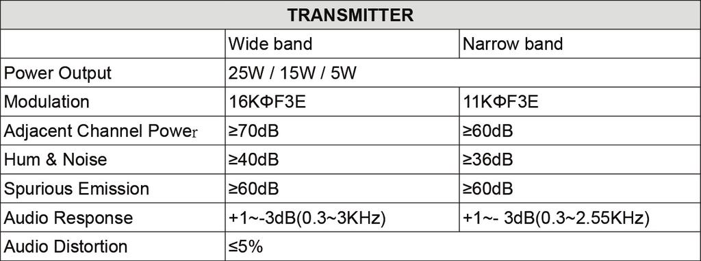
33 SPECIFICATIONS page 33
34 CTCSS TONE FREQUENCY CHART (HZ) No. Freq. (Hz) No. Freq. (Hz) No. Freq. (Hz) No. Freq. (Hz) No. Freq. (Hz) user defined page 34
35 DCS CODES FREQUENCY CHART Code No. DSC Code (Octal) No. DSC Code (Octal) No. DSC Code (Octal) No. DSC Code (Octal) No. DSC Code (Octal) No. DSC Code (Octal) No. DSC Code (Octal) No DSC (Octal) page 35
36 page 36
37 FCC WARNINGS AND STATEMENTS IMPORTANT! MIDLAND RADIO CORPORATION makes no warranty or claim regarding any modification to your DBR2500 not fully authorized by MIDLAND RADIO CORPORATION, nor any change in operability, performance, or regulatory compliance arising therefrom. You are solely responsible for operating your DBR2500 in accordance with the law. This device complies with Part 15 of the FCC Rules. Operation is subject to the following two conditions; (1) this device does not cause any harmful interference, and (2) this radio must accept any interference thay may cause undesired operations page 37
38 LIMITED WARRANTY (United States and Canada) Subject to the exclusions set forth below, Midland Radio Corporation will repair or replace, at its option without charge, any Midland UHF transceiver which fails due to a defect in material or workmanship within One Year following the initial consumer purchase. This warranty does not apply to water damage, battery leak, abuse or misuse of unauthorized accessories, unauthorized service or modification or altered products. Accessories have a 90 day warranty from date of purchase, including any antennas or chargers that are included with the unit. ANY IMPLIED WARRANTIES, INCLUDING, WITHOUT LIMITATION THE IMPLIED WARRANTIES OF MERCHANTABILITY AND FITNESS FOR A PARTICULAR PURPOSE, SHALL BE LIMITED AS SET FORTH HEREIN AND TO THE DURATION OF THE LIMITED WARRANTY, OTHERWISE THE REPAIR OR REPLACEMENT AS PROVIDED UNDER THIS EXPRESS LIMITED WARRANTY IS THE EXCLUSIVE REMEDY OF THE CONSUMER AND IS PROVIDED IN LIEU OF ALL OTHER WARRANTIES, EXPRESS OR IMPLIED. IN NO EVENT SHALL MIDLAND BE LIABLE, WHETHER IN CONTRACT OR TORT (INCLUDING BUT NOT LIMITED TO NEGLIGENCE, GROSS NEGLIGENCE, BODILY INJURY, PROPERTY DAMAGE AND DEATH) FOR DAMAGES IN EXCESS OF THE PURCHASE PRICE OF THE PRODUCT OR ACCESSORY, OR FOR ANY INDIRECT, INCIDENTAL, SPECIAL OR CONSEQUENTIAL DAMAGES OF ANY KIND, OR LOSS OF REVENUE OR PROFITS, LOSS OF BUSINESS, LOSS OF INFORMATION OR DATA OR OTHER FINANCIAL LOSS ARISING OUT OF OR IN CONNECTION WITH THE ABILITY OR INABILITY TO USE THE PRODUCTS OR ACCESSORIES TO THE FULL EXTENT THESE DAMAGES MAY BE DISCLAIMED BY LAW. For Product Purchased in the USA: Performance of any obligation under this warranty may be obtained by returning the warranted product, prepaid freight, along with proof of purchase to: Midland Radio Corporation Warranty Service Department 5900 Parretta Drive Kansas City, MO This warranty gives you specific legal rights, and you may also have other rights, which vary from state to state. NOTE: The above warranty applies only to merchandise purchased in the United States of America or any of the territories or possessions thereof, or from a U.S. Military exchange. page 38

39 page 39

40 5900 Parretta Drive Kansas City, MO Call We d love to hear from you! Let us know what you think of your new Midland product at or by visiting us at Note: Features & Specifications are subject to change without notice. MIDLAND is not responsible for unintentional errors or omissions on its packaging. page 40
INSTRUCTION MANUAL VHF FM TRANSCEIVER TK-190 KENWOOD CORPORATION B (K)
") INSTRUCTION MANUAL VHF FM TRANSCEIVER TK-190 KENWOOD CORPORATION B62-1175-00 (K) 09 08 07 06 05 04 03 02 01 00 THANK YOU We are grateful you chose KENWOOD for your land mobile radio applications. We believe
INSTRUCTION MANUAL VHF FM TRANSCEIVER TK-190 KENWOOD CORPORATION B62-1175-00 (K) 09 08 07 06 05 04 03 02 01 00 THANK YOU We are grateful you chose KENWOOD for your land mobile radio applications. We believe
ir3 INSTRUCTION MANUAL COMMUNICATIONS RECEIVER
 INSTRUCTION MANUAL COMMUNICATIONS RECEIVER ir3 This device complies with Part 15 of the FCC rules. Operation is subject to the following two conditions: (1) This device may not cause harmful interference,
Cellular Signal Booster
 Drive G-M Cellular Signal Booster THE ALUMINUM CASING OF YOUR SIGNAL BOOSTER!! WILL ADJUST TO THE TEMPERATURE OF ITS ENVIRONMENT, BUT IS DESIGNED TO PROTECT THE SIGNAL BOOSTER TECHNOLOGY. FOR EXAMPLE,
CAUTION RISK OF ELECTRIC SHOCK NO NOT OPEN
 Evolution Digital HD Set-Top Box Important Safety Instructions 1. Read these instructions. 2. Keep these instructions. 3. Heed all warnings. 4. Follow all instructions. 5. Do not use this apparatus near
PLL2210MW LED Monitor
 PLL2210MW LED Monitor USER'S GUIDE www.planar.com Content Operation Instructions...1 Safety Precautions...2 First Setup...3 Front View of the Product...4 Rear View of the Product...5 Quick Installation...6
Be sure to run the vehicle engine while using this unit to avoid battery exhaustion.
 CAUTION: TO REDUCE THE RISK OF ELECTRIC SHOCK DO NOT REMOVE COVER (OR BACK) NO USER-SERVICEABLE PARTS INSIDE REFER SERVICING TO QUALIFIED SERVICE PERSONNE; Please Read all of these instructions regarding
VNS2200 Amplifier & Controller Installation Guide
 VNS2200 Amplifier & Controller Installation Guide VNS2200 Amplifier & Controller Installation 1. Determine the installation location for the VNS2200 device. Consider the following when determining the
DDW36C Advanced Wireless Gateway - Safety and Installation Product Insert. Federal Communications Commission (FCC) Interference Statement
 Interference Statement") DDW36C Advanced Wireless Gateway - Safety and Installation Product Insert Federal Communications Commission (FCC) Interference Statement This equipment has been tested and found to comply with the limits
DDW36C Advanced Wireless Gateway - Safety and Installation Product Insert Federal Communications Commission (FCC) Interference Statement This equipment has been tested and found to comply with the limits
Automotive 72 Exterior Smart Lighting Kit
 PACKAGE CONTENTS Automotive 72 Exterior Smart Lighting Kit 36 36 8 x Wire Mounting Bracket 16 x Screws 60" Extension Cable 24 ON / OFF 60 Exterior Kit can also function as interior lighting Instruction
17 19 PROFESSIONAL LCD COLOUR MONITOR ART
 17 19 PROFESSIONAL LCD COLOUR MONITOR ART. 41657-41659 Via Don Arrigoni, 5 24020 Rovetta S. Lorenzo (Bergamo) http://www.comelit.eu e-mail:export.department@comelit.it WARNING: TO REDUCE THE RISK OF FIRE
PLL1920M LED LCD Monitor
 PLL1920M LED LCD Monitor USER'S GUIDE www.planar.com Content Operation Instructions...1 Safety Precautions...2 First Setup...3 Front View of the Product...4 Rear View of the Product...5 Installation...6
PL2410W LCD Monitor USER'S GUIDE.
 PL2410W LCD Monitor USER'S GUIDE www.planar.com Content Operation Instructions...1 Safety Precautions...2 First Setup...3 Front View of the Product...4 Rear View of the Product...5 Quick Installation...6
USER MANUAL. 27 Full HD Widescreen LED Monitor L27ADS
 USER MANUAL 27 Full HD Widescreen LED Monitor L27ADS TABLE OF CONTENTS 1 Getting Started 2 Control Panel/ Back Panel 3 On Screen Display 4 Technical Specs 5 Care & Maintenance 6 Troubleshooting 7 Safety
Instruction Guide. The TV Jockey Computer Monitor TV Tuner with Remote COMP2VGATVGB. The Professionals Source For Hard-to-Find Computer Parts
 VIDEO ADAPTER The TV Jockey Computer Monitor TV Tuner with Remote COMP2VGATVGB Instruction Guide * Actual product may vary from photo The Professionals Source For Hard-to-Find Computer Parts FCC COMPLIANCE
USER MANUAL. 22" Class Slim HD Widescreen Monitor L215DS
 USER MANUAL 22" Class Slim HD Widescreen Monitor L215DS TABLE OF CONTENTS 1 Getting Started Package Includes Installation 2 Control Panel / Back Panel Control Panel Back Panel 3 On Screen Display 4 Technical
User Manual MODEL: KKF1500-PCAP. True FLAT P-CAP LCD Monitor. Installation Guide. 15 True FLAT P-CAP Touch LCD Monitor
 True FLAT P-CAP LCD Monitor User Manual Installation Guide 15 True FLAT P-CAP Touch LCD Monitor MODEL: KKF1500-PCAP i-tech Company LLC TOLL FREE: (888) 483-2418 EMAIL: info@itechlcd.com WEB: www.itechlcd.com
2.0 Wall Mount TV Soundbar Instruction Manual
 8010275 2.0 Wall Mount TV Soundbar Instruction Manual Read all of the instructions before using this soundbar and keep the manual in a safe place for future reference. Safety Information CA UT IO N RISK
Documentation on all Paxton products can be found on our web site -
 11/05/2012 Ins-30202-US Net2 Entry - Monitor Paxton Technical Support 1.800.672.7298 supportus@paxton-access.com Technical help is available: Monday - Friday from 02:00 AM - 8:00 PM (EST) Documentation
CGA0101 Wireless Cable Gateway Quick Installation Guide
 Package Contents CGA0101 cable modem * 1 Quick Installation Guide * 1 RJ-45 CAT 5e cable * 1 Rear Panel and Hardware Connection 12 V/1.5 A Power Adaptor * 1 Telephone cord * 1 This chapter describes the
Evolution Digital HD Set-Top Box Important Safety Instructions
 Evolution Digital HD Set-Top Box Important Safety Instructions 1. Read these instructions. 2. Keep these instructions. 3. Heed all warnings. 4. Follow all instructions. 5. Do not use this apparatus near
Register your product and get support at SDV5122/27. EN User manual
 Register your product and get support at www.philips.com/welcome SDV5122/27 User manual Contents 1 Important 4 Safety 4 Notice for USA 5 Notice for Canada 5 Recycling 6 English 2 Your SDV5122 7 Overview
Hi-Vision TV Box. High Resolution TV BOX with PIP feature Model:174190
 Operational Manual Hi-Vision TV Box High Resolution TV BOX with PIP feature Model:174190 Thanks for your purchasing this product. Please read the Manual carefully before using it, and keep this manual
Scoreboard Operator s Instructions MPCX SCD / DGT / Pitch Time Control
 Scoreboard Operator s Instructions MPCX SCD / DGT / Pitch Time Control Since 1934 Retain this manual in your permanent files Rev. 2/3/2012 135-0136 These Instructions are for the Following Models: LED
Before you can install your LCD TV on the wall, you must fi rst remove the base using the steps below:
 Quick Start Guide English CONTENTS INSTALLING LCD TV ON THE WALL.. TV CHANNEL INSTALLATION........ PRESENTATION OF THE LCD TV...... ACCESSORIES.................... BATTERY INSTALLATION............ REMOTE
TMX-R1000 (USA and JAPAN) TMX-R1000P (EUROPE)
 TMX-R1000P (EUROPE)") ALPINE ELECTRONICS, INC. TMX-R1000 (USA and JAPAN) TMX-R1000P (EUROPE) VGA MOBILE CINEMA MONITOR OWNER S MANUAL Features 10.2 inch Wide VGA TFT Active Matrix Color LCD (800 x 480) 3 AUX In / 1 AUX Out
ALPINE ELECTRONICS, INC. TMX-R1000 (USA and JAPAN) TMX-R1000P (EUROPE) VGA MOBILE CINEMA MONITOR OWNER S MANUAL Features 10.2 inch Wide VGA TFT Active Matrix Color LCD (800 x 480) 3 AUX In / 1 AUX Out
User Manual MODEL: KK1500-TR. Touch Display LCD Monitor. Installation Guide. 15 Resistive Touch LCD Monitor
 Touch Display LCD Monitor User Manual Installation Guide 15 Resistive Touch LCD Monitor MODEL: KK1500-TR i-tech Company LLC TOLL FREE: (888) 483-2418 EMAIL: info@itechlcd.com WEB: www.itechlcd.com User
USER MANUAL. 28" 4K Ultra HD Monitor L28TN4K
 USER MANUAL 28" 4K Ultra HD Monitor L28TN4K TABLE OF CONTENTS 1 Getting Started 2 Control Panel/ Back Panel 3 On Screen Display 4 Technical Specs 5 Care & Maintenance 6 Troubleshooting 7 Safety Info &
17" & 19" Color TFT LCD Monitor
 17" & 19" Color TFT LCD Monitor KMC-17B & KMC-19B User's Manual for Operation and installation Screen Size : KMC-17B (17" inch TFT LCD) KMC-19B (19" inch TFT LCD) Display Size : KMC-17B (337.920mm X 270.336mm)
MONOPRICE. BitPath AV HDMI Extender over Single Cat6 Cable, 120m. User's Manual P/N 16228
 MONOPRICE BitPath AV HDMI Extender over Single Cat6 Cable, 120m P/N 16228 User's Manual SAFETY WARNINGS AND GUIDELINES Please read this entire manual before using this device, paying extra attention to
HD Digital Set-Top Box Quick Start Guide
 HD Digital Set-Top Box Quick Start Guide Eagle Communications HD Digital Set-Top Box Important Safety Instructions WARNING TO REDUCE THE RISK OF FIRE OR ELECTRIC SHOCK, DO NOT EXPOSE THIS PRODUCT TO RAIN
OWNER S MANUAL MOTORIZED 7 WIDE TFT LCD COLOR MONITOR CNT-701
 OWNER S MANUAL PW MOTORIZED 7 WIDE TFT LCD COLOR MONITOR CNT-701 ANY CHANGES OR MODIFICATIONS IN CONSTRUCTION OF THIS UNIT DEVICE WHICH IS NOT APPROVED BY THE PARTY RESPONSIBLE FOR COMPLIACE COULD VOID
HD Digital MPEG2 Encoder / QAM Modulator
 HD Digital MPEG2 Encoder / QAM Modulator HDMI In QAM Out series Get Going Guide ZvPro 800 Series is a one or two-channel unencrypted HDMI-to-QAM MPEG 2 Encoder / QAM Modulator, all in a compact package
TV Connector user guide
 TV Connector user guide Thank you Thank you for choosing the TV Connector. The intended use of the TV Connector is to connect your hearing aids directly to your TV or audio source. Your TV Connector Hearing
USER MANUAL. 27" 2K QHD LED Monitor L27HAS2K
 USER MANUAL 27" 2K QHD LED Monitor L27HAS2K TABLE OF CONTENTS 1 Getting Started 2 Control Panel/ Back Panel 3 On Screen Display 4 Technical Specs 5 Troubleshooting 6 Safety Info & FCC warning 1 GETTING
Inside the Box. Touchscreen LCD 1 WAN 2 LAN. Reset Button. Power Connector. Stylus
 Inside the Box Touchscreen LCD 1 WAN 2 LAN Reset Button Power Connector Stylus 12V, 1A Power Adapter Ethernet Cable The setup process consists of a few simple steps: 1) Connect Almond to the Internet in
Wireless Sound Bar *MFL * SIMPLE MANUAL
 ENGLISH SIMPLE MANUAL Wireless Sound Bar To view the instructions of advanced features, visit http://www.lg.com and then download Owner s Manual. Some of the content in this manual may differ from your
UNFOLD THE BASE. Quick Start Guide CONTENTS INSTALLING LCD TV ON THE WALL
 Quick Start Guide English CONTENTS INSTALLING LCD TV ON THE WALL.. UNFOLD THE BASE............... TV CHANNEL INSTALLATION........ PRESENTATION OF THE LCD TV..... ACCESSORIES.................... BATTERY
2.4GHz Digital Wireless Video Door Phone User Manual
 2.4GHz Digital Wireless Video Door Phone User Manual Thank you for purchasing our product. For better taking advantage of the prior functions please carefully read user manual for correct installation
 Register your product and get support at www.philips.com/welcome SDV5222T/27 User manual Contents 1 Important 4 Safety 4 Notice for USA 4 Notice for Canada 5 Recycling 5 English 2 Your SDV5222T 6 Overview
CINEGEARS MULTI AXIS FOLLOW FOCUS KIT V3 MANUAL BOOK Cine Gears INC. All Rights Reserved.
 CINEGEARS MULTI AXIS FOLLOW FOCUS KIT V3 MANUAL BOOK Statement of Conditions In the interest of improving internal design, operational function, and/or reliability, Cine Gears Inc. reserves the right to
LCD VALUE SERIES (32 inches)
") LCD VALUE SERIES (32 inches) http://www.orionimages.com All contents of this document may change without prior notice, and actual product appearance may differ from that depicted herein 1. SAFETY INSTRUCTION
LCD VALUE SERIES (32 inches) http://www.orionimages.com All contents of this document may change without prior notice, and actual product appearance may differ from that depicted herein 1. SAFETY INSTRUCTION
TFT LCD MONITOR USER MANUAL. L80AP and L101AP
 TFT LCD MONITOR USER MANUAL L80AP - 8.0 and L101AP - 10.1 Table Of Contents Table of contents/ Warning.... 2 Precautions...3 About this user manual and products / Items included in the delivery..... 4
PXL2760MW LED LCD Monitor
 PXL2760MW LED LCD Monitor USER'S GUIDE www.planar.com Content Operation Instructions...1 Safety Precautions...2 Package Overview...3 First Setup...4 Front View of the Product...5 Rear View of the Product...6
Scoreboard Operator s Instructions MPCX Volleyball Control
 Scoreboard Operator s Instructions MPCX Volleyball Control Since 1934 Retain this manual in your permanent files Rev. 2/3/2012 135-0137 These Instructions are for the Following Models: LED models: Incandescent
MONOPRICE. BitPath AV SDI Extender over Single Cat6 Cable, 120m. User's Manual P/N 16227
 MONOPRICE BitPath AV SDI Extender over Single Cat6 Cable, 120m P/N 16227 User's Manual SAFETY WARNINGS AND GUIDELINES Please read this entire manual before using this device, paying extra attention to
USER MANUAL Full HD Widescreen LED Monitor L215IPS
 USER MANUAL 21.5 Full HD Widescreen LED Monitor L215IPS TABLE OF CONTENTS 1 Getting Started 2 Control Panel/ Back Panel 3 On Screen Display 4 Technical Specs 5 Care & Maintenance 6 Troubleshooting 7 Safety
User s Guide. 5.8GHz Wireless A/V Signal Sender
 1500332 User s Guide 5.8GHz Wireless A/V Signal Sender Thank you for purchasing your A/V Signal Sender from RadioShack. Please read this user s guide before installing, setting up, and using your new sender.
FD Trinitron Colour Television
 R 4-205-569-32(1) FD Trinitron Television Instruction Manual GB KV-14LM1U 2000 by Sony Corporation NOTICE FOR CUSTOMERS IN THE UNITED KINGDOM A moulded plug complying with BS1363 is fitted to this equipment
Ambient Weather WS-01 Intelligent Color Changing Temperature Night Light with Ambient Backlight User Manual
 Ambient Weather WS-01 Intelligent Color Changing Temperature Night Light with Ambient Backlight User Manual Table of Contents 1 Introduction... 1 2 Warnings... 2 3 Getting Started... 2 3.1 Parts List...
Satellite Radio. Expand Your Factory Radio ISSR bit & 29-bit LAN. Owner s Manual Gateway. add. Harness Connection USB. Port 1 Port.
 Expand Your Factory Radio Harness Connection add Satellite Radio Dip Switches Port 1 Port 2 (See Manual) USB GM 11-bit & 29-bit LAN Owner s Manual Gateway ISSR12 Table of Contents 1. Introduction 2. Precautions
In-Line or 75 Ohm In-Line
 or 5 Ohm 1dB Adjustable Gain 800/1900 Smart Technology Contents: Quick Install Overview.... 2 Installation Diagram.... Understanding the Lights... 9 Warnings and Recommendations....11 Appearance of device
Owner's Manual DIGITAL TO ANALOG BROADCAST CONVERTER WITH REMOTE CONTROL. Model: CVD508 PLEASE READ BEFORE OPERATING THIS EQUIPMENT.
 Size: 148.5(W) x 210(H)mm (A5) DIGITAL TO ANALOG BROADCAST CONVERTER WITH REMOTE CONTROL Owner's Manual PLEASE READ BEFORE OPERATING THIS EQUIPMENT. Model: CVD508 FCC NOTICE: To assure continued compliance,
PLL2710W LED LCD Monitor
 PLL2710W LED LCD Monitor USER'S GUIDE www.planar.com Content Operation Instructions...1 Safety Precautions...2 Package Overview...3 First Setup...4 Front View of the Product...5 Rear View of the Product...6
Rain+Birdt. Landscape Irrigation & Maintenance Remote System. Quick Start Guide 4.00 F G H K 9X. c n. System Components
 Rain+Birdt Landscape Irrigation & Maintenance Remote System Quick Start Guide 4.00 D System Components A Transmitter (TX) B Receiver (RX) C Quick Connect (QC) 6-Pin Quick Connect (QC) for use with ESP-Modular
HD Digital MPEG2 Encoder / QAM Modulator
 HD Digital MPEG2 Encoder / QAM Modulator YPrPb VGA In QAM Out series Get Going Guide ZvPro 600 Series is a one or two-channel Component or VGA-to-QAM MPEG 2 Encoder/ Modulator, all in a compact package
Expand Your Factory Radio add Satellite Radio Harness Connection
 Expand Your Factory Radio Harness Connection add Satellite Radio Dip Switches Port 1 Port 2 (See Manual) USB Honda/Acura Owner s Manual GateWay Owner s Manual Media ISSR12 GateWay PXAMG 01-22-13 Table
USER MANUAL Full HD Widescreen LED Monitor L215ADS
 USER MANUAL 21.5 Full HD Widescreen LED Monitor L215ADS TABLE OF CONTENTS 1 Getting Started 2 Control Panel/ Back Panel 3 On Screen Display 4 Technical Specs 5 Care & Maintenance 6 Troubleshooting 7 Safety
Welcome to NEED HELP? DIRECTV offers the best entertainment experience. Use this guide to make the most of it LKR FCC ID : ORS
 NEED HELP? Important Tips Do not unplug your receiver If you unplug it you may miss the most recent updates that improve our service. The DIRECTV receiver is designed to consume very little energy while
SIR-GM1 GM CLASS-2 BUS COMPATIBLE SIRIUS SATELLITE RADIO TUNER
 SIR-GM1 GM CLASS-2 BUS COMPATIBLE SIRIUS SATELLITE RADIO TUNER Installation Guide Congratulations on your purchase of the SIR-GM1 the GM Compatible SIRIUS Satellite Radio Tuner! Your SIR-GM1 is designed
USER MANUAL. 27 Full HD Widescreen LED Monitor L270E
 USER MANUAL 27 Full HD Widescreen LED Monitor L270E TABLE OF CONTENTS 1 Getting Started 2 Control Panel/ Back Panel 3 On Screen Display 4 Technical Specs 5 Care & Maintenance 6 Troubleshooting 7 Safety
USER MANUAL Full HD Widescreen LED Monitor L236VA
 USER MANUAL 23.6 Full HD Widescreen LED Monitor L236VA TABLE OF CONTENTS 1 Getting Started 2 Control Panel/ Back Panel 3 On Screen Display 4 Technical Specs 5 Care & Maintenance 6 Troubleshooting 7 Safety
MONOPRICE. BitPath AV VGA Extender over Single Cat6 Cable, 120m. User's Manual P/N 16226
 MONOPRICE BitPath AV VGA Extender over Single Cat6 Cable, 120m P/N 16226 User's Manual SAFETY WARNINGS AND GUIDELINES Please read this entire manual before using this device, paying extra attention to
CONTENTS 8 ACCESSORIES 13 9 TROUBLE SHOOTING AND ADVICE SPECIFICATIONS BATTERY USAGE CAUTION 13
 CONTENTS 1 PREFACE 2 2 SAFETY PRECAUTIONS 2 3 FRONT & BACK VIEW, REAR CONNECTION OF LCD 3 4 TV INSTALLATION DRAWINGS 4 4.1 ANTENNA CONNECTION 4 4.2 AV1 INPUT CONNECTION 4 4.3 AV2 INPUT CONNECTION 4 4.4
Connevans.info. DeafEquipment.co.uk. This product may be purchased from Connevans Limited secure online store at
 Connevans.info Solutions to improve the quality of life Offering you choice Helping you choose This product may be purchased from Connevans Limited secure online store at www.deafequipment.co.uk DeafEquipment.co.uk
Cellular Signal Booster
 Drive 4G-X Cellular Signal Booster THE ALUMINUM CASING OF YOUR SIGNAL BOOSTER!! WILL ADJUST TO THE TEMPERATURE OF ITS ENVIRONMENT, BUT IS DESIGNED TO PROTECT THE SIGNAL BOOSTER TECHNOLOGY. FOR EXAMPLE,
IPSTB1200 /IPC3200 Media Client User guide
 IPSTB1200 /IPC3200 Media Client User guide Safety/Compliance Important Safety Instructions Please carefully read these safety and compliance instructions and this entire user guide. Follow all instructions
MODEL HA07 - MASTER CONTROLLER INSTRUCTIONS
 Thank you for purchasing Intermatic s Home Settings devices. With these products you can reliably and remotely control lighting and appliances. The outstanding features of the Home Settings program include:
PREPROGRAMMED FOR YOUR SET-TOP BOX
 New Knoxville Telephone NKTELCO, Inc. Goldstar Communications 301 W. South Street PO Box 219 New Knoxville, OH 45871 PREPROGRAMMED FOR YOUR SET-TOP BOX ADB Remote Functions 1 New Knoxville Telephone 301
TV CHANNEL INSTALLATION
 LCD TV TV CHANNEL ATION Immediately after unpacking and plugging in your new television, run the auto program function to set up the TV for the broadcast or cable channels available in your area. If you
DCL9AW. User Manual. English
 DCL9AW User Manual English PRECAUTIONS Information for users applicable in European Union countries 1 Information for users applicable in United States of America 1 Installation 1 Power connection 1 Maintenance
PXL2470MW LED LCD Monitor
 PXL2470MW LED LCD Monitor USER'S GUIDE www.planar.com Content Operation Instructions...1 Unpacking Instructions...2 Safety Precautions...2 Package Overview...3 First Setup...4 Front View of the Product...5
TV Connector user guide
 TV Connector user guide Thank you Thank you for choosing the TV Connector. The intended use of the TV Connector is to connect your hearing aids directly to your TV or audio source. Your TV Connector Hearing
Introduction. Important Safety Instructions
 Introduction Congratulations on purchasing your Eviant Portable Digital TV. On June 12, 2009 the conversion to digital television broadcasting will be complete all throughout the United States and Puerto
InnoMedia ESBC B. Quick Install Guide. 1
 InnoMedia ESBC 9528-4B Quick Install Guide www.innomedia.com 1 Table of Contents Introduction 3 Package Contents 3 CAUTION 3 Installation 4 Wall-Mounting Instructions 6 Troubleshooting 7 Appendix A. LED
It will cause malfunction if the monitor is operating with unspecified power supply
 User Manual / Installation Guide Model No. PTM-1525R/RT Warning! It will cause malfunction if the monitor is operating with unspecified power supply unit or incorrect power voltage. Do not exposure this
Monochrome Video Monitors
 Instructions for Use Monochrome Video Monitors En F D E NL I LTC 2009 LTC 2012 LTC 2017 Philips Communication & Security Systems GB F D E NL I Instructions for Use...1.1 Mode d emploi...2.1 Bedienungsanleitung...3.1
User Manual MODEL: KKW700V. Non-Touch True Display LCD Monitor. Installation Guide. 7 True Display LCD Monitor (VGA Interface)
") Non-Touch True Display LCD Monitor User Manual Installation Guide 7 True Display LCD Monitor (VGA Interface) MODEL: KKW700V i-tech Company LLC TOLL FREE: (888) 483-2418 EMAIL: info@itechlcd.com WEB: www.itechlcd.com
Non-Touch True Display LCD Monitor User Manual Installation Guide 7 True Display LCD Monitor (VGA Interface) MODEL: KKW700V i-tech Company LLC TOLL FREE: (888) 483-2418 EMAIL: info@itechlcd.com WEB: www.itechlcd.com
Always there to help you. Register your product and get support at SRP5018. Question? Contact Philips.
 Always there to help you Register your product and get support at www.philips.com/support Question? Contact Philips SRP5018 User manual Contents 1 Your universal remote 2 Introduction 2 Overview of the
In-Ceiling Electric Motorized Front Projection Screen Evanesce Series. User s Guide
 In-Ceiling Electric Motorized Front Projection Screen Evanesce Series User s Guide Important Safety & Warning Precautions Make sure to read this user s guide and follow the procedures below. Caution: The
Interactive Satellite Terminal Installation / Validation Manual
 Installation / Validation Manual Version October 5, 2016 Index INTERACTIVE SATELLITE TERMINAL 1. FCC COMPLIANCE... 3 2. TECHNICAL FEATURES...4 3. GENERAL DESCRIPTION...5 4. ELEMENTS CONTAINED IN THE TERMINAL...6
NMS ETA TM Stereo Advanced Digital TV Set-top Box
 Digital TV HD Set-top Box STB2-T2 NMS ETA TM Stereo Advanced Digital TV Set-top Box User Guide CONTENTS Safety Information... 3 Introduction... 4 Set-top Box Front Panel... 4 Set-top Box Back Panel...
2.4 GHz WIRELESS VIDEO SENDER SYSTEM MODEL: VS6234
 2.4 GHz WIRELESS VIDEO SENDER SYSTEM MODEL: VS6234 Please read this manual thoroughly before operating this system OPERATING INSTRUCTIONS 03/02 1 SAFETY INSTRUCTIONS CAUTION! RISK OF ELECTRIC SHOCK. DO
ZXV10 B760H ZXV10 B760E RichMedia Box User Guide
 ZTE CORPORATION NO.55,Hi-techRoadSouth,ShenZhen,P.R.China Postcode:518057 Tel: (86) 755 26771900 800-9830-9830 Fax: (86) 755 26772236 URL: http://support.zte.com.cn E-mail: doc@zte.com.cn ZXV10 B760H ZXV10
Reference WIRING THE SYSTEM TOGETHER. Page 4-1 TWO OR MORE RECEIVERS
 4 Reference WIRING THE SYSTEM TOGETHER TWO OR MORE RECEIVERS Each output on the LNBF can support a single receiver. You cannot connect two receivers to the same output (for example, by using a line splitter),
Wireless 5.8GHz AV Sender With Built in Remote Control Extender
 Wireless 5.8GHz AV Sender With Built in Remote Control Extender AR-1913 User Manual TABLE OF CONTENTS Box Contents..................2 User Guide.............3 Installation............4 Trouble Shooting............
Check our knowledge base at
 USER MANUAL Check our knowledge base at www.paralinx.net/support Copyright 2015 Paralinx LLC All Rights Reserved TABLE OF CONTENTS 1 Important Notice 10 LCD Screen 2 Safety Instructions 11 Indicators 3
2. only. INTRODUCTION...3. Do SPECIFICATION...3 SYSTEM SETTINGS...7. Installation. Troubleshooting. OVERVIEW Important Information
 www.switronix.com Troubleshooting Installation Important Information Read Step1: REC this user s REC X5TX manual X5TX carefully before transmitter: use. It contains important information notes regarding
USER GUIDE. DM Engineering Multi Station Relay Adapter (MSRA and MSRA-RM) Version DM Engineering
 Version DM Engineering") USER GUIDE DM Engineering Multi Station Relay Adapter (MSRA and MSRA-RM) Version 1.35 DM Engineering 2174 Chandler St. Camarillo, CA 91345-4611 805-987-7881 800-249-0487 www.dmengineering.com Overview:
USER GUIDE DM Engineering Multi Station Relay Adapter (MSRA and MSRA-RM) Version 1.35 DM Engineering 2174 Chandler St. Camarillo, CA 91345-4611 805-987-7881 800-249-0487 www.dmengineering.com Overview:
ANALOGUE DEMODULATOR OWNERS MANUAL
 ANALOGUE DEMODULATOR OWNERS MANUAL TABLE OF CONTENTS Package Content.... 1 About The ADM5... 2 Front & Rear Panels.. 3 Illustration of Basic Connection... 4 Procedure of Set Up... 5-7 Remote Controller
Safety Information. Camera System. If you back up while looking only at the monitor, you may cause damage or injury. Always back up slowly.
 Table of Contents Introduction...3 Safety Information...4-6 Before Beginning Installation...7 Installation Guide...8 Wiring Camera & Monitor...9-10 Replacement Installation Diagram...11 Clip-On Installation
ZvBox 150. HD video distribution over COAX Get Going Guide
 ZvBox 150 HD video distribution over COAX Get Going Guide ZvBox 150 is an HD MPEG 2 Encoder and frequency agile QAM Modulator. It allows you to convert any HD video source, Component or RGB (VGA), in real
 Register your product and get support at www.philips.com/welcome SDV8625T/27 User manual Contents 1 Important 4 Safety 4 For indoor use 4 For outdoor use 4 Notice for USA 4 Notice for Canada 5 Recycling
ROUGH DRAFT. Guide. Installation. Signal Booster. Wilson. AG Pro 75 Smart Technology In-Building Wireless 800/1900 Signal Booster.
 Signal Booster Installation Guide Contents: AG Pro 75 Smart Technology In-Building Wireless 800/1900 Signal Booster Before Getting Started.... 1 Antenna Options & Accessories.................... 1 Easy
MP-7424 Football Scoreboard with MP5000 Console
 MP-7424 Football Scoreboard with MP5000 Console With additional instructions for Track and Soccer Operator s Manual Volume VII Rev. 10/17/07 Table of Contents Table of Contents...2 1.0 Keypad Console...3
RA-RS232, RB-RS232. Setup and Installation Guide Addendum For RadioRA RS232 Interface
 RA-RS232, RB-RS232 Setup and Installation Guide Addendum For RadioRA RS232 Interface A Comprehensive Step-by-Step Guide for Programming and Operating the Lutron RadioRA RS232 Interface Note: Please leave
Instruction Manual Digital Wireless Intercom SAMCOM FTAN20AA
 Instruction Manual Digital Wireless Intercom SAMCOM FTAN20AA Features of Model FTAN20AA Simple to use" Instant" Intercom system. Individually call and Group call function. Connect ability to other hand
DISTRIBUTION AMPLIFIER
 MANUAL PART NUMBER: 400-0045-005 DA1907SX 1-IN, 2-OUT VGA/SVGA/XGA/UXGA DISTRIBUTION AMPLIFIER USER S GUIDE TABLE OF CONTENTS Page PRECAUTIONS / SAFETY WARNINGS... 2 GENERAL...2 GUIDELINES FOR RACK-MOUNTING...2
 Register your product and get support at www.philips.com/welcome SWS3435S/27 SWS3435H/37 EN User manual Contents 1 Important 4 Safety 4 English 2 Your SWS3435 6 Overview 6 3 Installation 7 Connect the
Satellite Radio. Owner s Manual. Expand Your Factory Radio. Honda/Acura PXAMG. GateWay. add
 Expand Your Factory Radio Harness Connection add Satellite Radio Dip Switches Port 1 Port 2 (See Manual) USB Honda/Acura Owner s Manual GateWay Owner s Manual Media ISSR12 GateWay PXAMG isimple A Division
THD601DC Set-top box
 THD601DC Set-top box Contents 1. Safety... 1 2. Appearance... 2 3. Rear Panel Connection... 3 4. Remote... 4 5 First Time Set-Up... 7 6. Network Settings... 8 6.1 Available Networks and Checking Current