Signaling with CATS & JMRI
|
|
|
- Duane Booker
- 6 years ago
- Views:
Transcription

1 Signaling with CATS & JMRI Dick Johannes & the HUB Division Signal Committee May /15/2016 1


2 The HUB Division Signal Committee Members 5/15/2016 2
3 Hoosac, Upton & Boston RR Now over 65 members Dick Ball is the current Superintendent Very large setups including the annual Amherst Railway Society Show & our New England Model Train Expo Annual displays at Children s Hospital Boston & the National Heritage Museum in Lexington, MA Shown internationally: Canada, Germany, Netherlands Very early adopter of DCC (after all, Stan and Debbie Ames are members) Has always been Lenz driven 1 st Place awards at NMRA Nationals both in individual modules and modular railroad categories. 5/15/2016 3
4 Goals & Rationale Increase the knowledge and curiosity in signaling within HUB Division members Add a new level of operating interest to the modular layout Enhance the viewing experience for spectators of the layout Sounded like fun!! 5/15/2016 4
5 Key historical events 1840: Ball signals: LTC Rolt 1841: Semaphore Charles Gregory 1851:Telegraph Chas Minot 1870: Track Circuit William Robinson 1871: Disk (Banjo) Signal Thomas Hall 1904: Color light signals William Churchill 1915: Position-light signals Arthur Rudd 1920: Searchlight Signals Hall Signal Co. 1924: Color Position signals Frank Patenall 1925: Tri-color (G type) signals - GRS 5/15/2016 5
6 Two types of regions Interlockings (Junctions & Sidings) Block A Block B Block C Block D Block E Block F Block G Linear Blocks 5/15/2016 6
7 The Distinctions Linear blocks Unsupervised (e.g. totally automated) Default is clear or green ABS (Automatic Block Signaling) APB (Absolute Permissive Block) Interlockings (Junctions & Sidings) Supervised (e.g. human controlled) Default is stop or red Mechanical interlocks US&S panels Computerized CTC 5/15/2016 7
8 Aspects: NORAC* Rule: 281 Name: Clear Indication: Proceed not exceeding Normal Speed Rule: 281c Name: Limited Clear Indication: Proceed at Limited Speed until entire train clears all interlocking or spring switches Rule: 281a Name: Cab Speed Indication: Proceed in accordance with cab signal indication Rule: 282 Name: Approach Medium Indication: Proceed approaching the next signal at Medium Speed 5/15/2016 Rule: 281b Name: Approach Limited Indication: Proceed approaching the next signal at Limited Speed * 9 th Edition, Flashing Rule: 282a Name: Advance Approach Indication: Proceed prepared to stop at the second signal. Trains exceeding Limited Speed must reduce to Limited Speed as engine passed the signal 8
9 Aspects: NORAC* (cont) Rule: 283 Name: Medium-Clear Indication: Proceed at Medium Speed until entire train clears all interlocking or spring switches, then proceed at Normal Speed Rule: 283a Name: Medium Approach Medium Indication: Proceed at Medium Speed until entire train clears all interlocking or spring switches, then approach next signal at Medium Speed Rule: 284 Name: Approach Slow Indication: Proceed approaching the next signal at Slow Speed Rule: 285 Name: Approach Indication: Proceed prepared to stop at the next signal. Reduce to Medium Speed as engine passes signal Rule: 286 Name: Medium Approach Indication: Proceed prepared to stop at the next signal. Reduce to Medium Speed as soon as signal is clearly visible Rule: 287 Name: Slow Clear Indication: Proceed at Slow Speed until entire train clears all interlocking or spring switches, then proceed at Normal Speed * 9 th Edition, Flashing 5/15/2016 9
10 We Built 5 Test Modules Two were passive (e.g. do not have a signaling card) No detection No signals These represented unchanged modules Three were active modules (e.g. have a signaling card) These 3 modules all contained signals Each module used a different type of signal 1 used G-type, 1 used Searchlight, 1 used D-type All wired as common anode NCE AIU & DB20s used for detection, Oaktree signal boards Wiring strategy: Inner main supplies power & detection to the left Outer main supplies power & detection to the right 5/15/


11 The Test Modules Three Active Modules CTC OS Module CTC Crossover Module Straight Module 5/15/

12 The Six Permutations 5/15/
13 Permutation of Module Order 5/15/

14 US&S CTC Panels Screen shot from Dick Bronson s Hartford National Clinics 5/15/
15 But There Was Interest in a Modern CRT-based Panel We looked at the Layout Editor Using the JMRI Website, we found CATS (Computer Automated Traffic System) Open Source JAVA software layered atop PanelPro Written by Rodney Black. Like JMRI, it has an online user forum Based upon prototype Digicon system 5/15/
16 CATS Suite is 3 Programs DESIGNER Used to describe the panel (e.g. track, turnouts & signals) Creates a permanent stored XML file Detector and signal definitions & address mapping Many display options CATS The runtime application Many runtime controls and display options TRAINSTAT Tool to allow documenting train location and time (either real time or fast clock) Can be stored to file for archiving 5/15/
17 CATS Several outstanding features Uses all the debugging tools in JMRI Great benefits even without signals Signaling based on 4 track speed / 2 or 3 block rules Pre-programmed signal logic CTC signals are visible whereas intermediate signals can be invisible on the dispatcher panel Can grant track authority Can take track out of service Allows train tracking by train symbol or locomotive # Well written online manuals 5/15/
18 CATS & Arbitrary Module Order How does one swap module order and preserve signal logic? The File Import function File->Import reads in a saved layout (a library) without erasing any existing work. It is a way to merge multiple layouts together, add some pre-canned design elements to the existing layout, insert existing signal definitions, etc. When a file is selected, designer will grab the track plan from the file and insert the upper grid corner of the trackplan at the grid cursor location. It will expand the layout in the horizontal and vertical directions as needed. Note that the library is not inserted, but replaces existing track; thus, preserving any track not overlaid Tracks, information associated with tracks (e.g. Block definitions), Stations, Signals, etc. will be added to the existing work. File->Import will also merge any Devices (Section 8) defined in the file, but not any Appearances (Section 14.1), Trains (Section 10), Crew (Section 12), or Jobs (Section 11). Merging is defined as if something in the file does not exist in the current trackplan, it is added. This means that things in the library file will not replace things with the same name in the trackplan. 5/15/
19 Insertion Demonstration 5/15/


20 Architecture JMRI & CATS WIFI WIFI WiThrottle and Engine Commander Lenz LAN/USB RS 485 Cable C/MRI Outputs XpressNet Command Station DCCOD C/MRI Net Booster 1 Occupancy Feedback DCC Track Power Point Feedback Booster 2 DCC Accessory Power Stationary Decoder Turnout Motor

21 Screenshot: the Digicon Prototype 5/15/

22 CATS Rendering of the Prototype 5/15/
23 Locks Route Locking: Prevents realigning a turnout while a selected route is occupied Indication Locking: Prevents realigning a turnout or clearing a conflicting signal when a signal for entry into the route has been cleared Time Locking: Prevents realigning a turnout or clearing a conflicting signal for a period of time after the dispatcher has knocked down a cleared signal 5/15/
24 Speed 1. Maximum authorized (Normal) 2. Limited 45 mph 3. Medium 30 mph 4. Slow 20 mph Prototypical Frog Number Typical Model Frog Number Typical Usage model & prototype Typical Prescribed speed for model (scale mph) 8 4 Tight yard & industrial tracks Moderate yards & industrial tracks Broad yard, branch lines & Main track slow speed turnout Main track medium speed turnout Main track limited speed turnout 45 5/15/


25 Speed vs. Route Signaling Fundamentally, there are two different schools of thought regarding how Route prototype signal aspects should Speed be used for controlling Signaling train movements through interlocking Signaling controlled turnouts. The first, called Speed Signaling, uses aspects to define the specific speed that a train may travel through an interlocking plant. The second, called Route Signaling, simply uses aspects to define that a train is set up to take the diverging route through the interlocking plant. -Dr. Bruce Chubb, MRC February 2016 Dr. Bruce Chubb RMC, Mar 2016 Dr. Bruce Chubb RMC, Feb /15/
 5/15/2016")
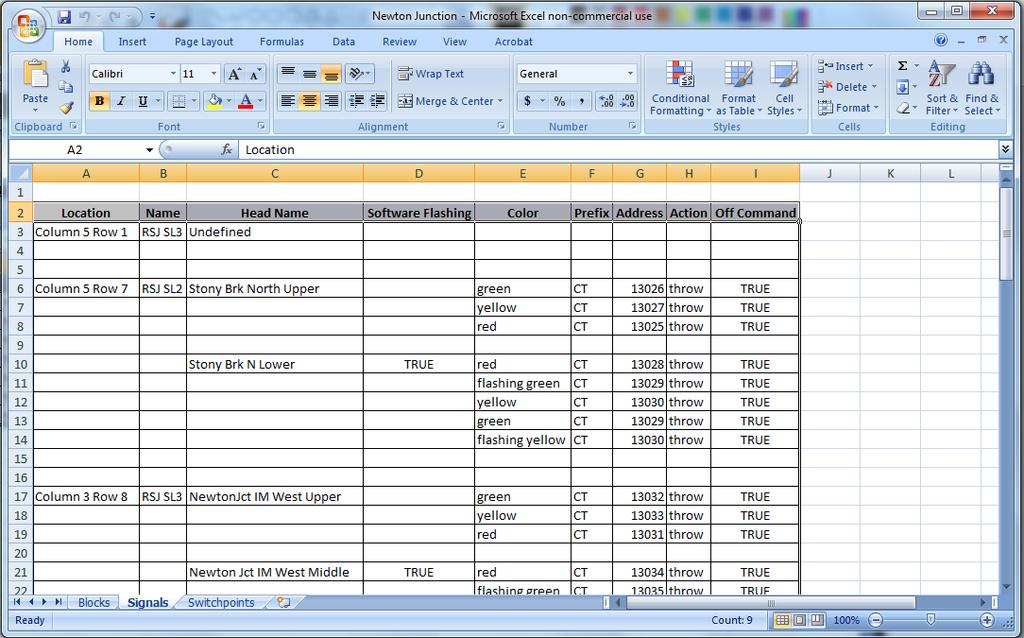
26 The Signal Template (Defaults) 5/15/

27 Define Your Signal Rules 5/15/
28 The Signal Template (HUB Edited) 5/15/
29 References (Books) Railroad Signaling. Brian Soloman, MBI Publishing How to operate your model railroad. Bruce A Chubb, 2 nd Edition, Kalmbach, Realistic Model Railroad Operation. Tony Koester. Kalmbach The Model Railroaders Guide to Junctions. Jeff Wilson. Kalmbach Railroader's C/MRI Applications Handbook V3.0 (Volumes 1,2,&3 Especially Vol 2). Bruce Chubb. Available through JLC Enterprises. Railroad Operation and Railway Signaling. Edmund J Phillips. Simmons-Boardman 1942 Compendium of Signals. Roger F.R Karl. Boynton, All About Signals. John Armstrong, Kalmbach, New Electronic Projects for Model Railroaders. Peter J Thorne, Kalmbach, /15/
30 References (Journals) Operating signals with software. Model Railroader, October 2007, page 50. The Computer/Model Railroad Interface - A Case Study. Model Railroading, December 1999/January 2000, page 32. Using State-of-the-art Electronics to Enhance Operation. NMRA Bulletin, March 2007 page 38. Where to place trackside signals. Model Railroader, October 2007, page 52. Signaling: by Bruce Chubb (n-part article). Railroad Model Craftsman, December 2015-May? Absolute-Permissive Block Signals (3 part article). Model Railroader, November 1991 page 128. Centralized traffic control for the Cat Mountain Line. Model Railroader, May 1984, page 74. 5/15/
31 References (Web Sites) Carsten Lundstens site: Norac Simulator: Railroad Signals: Railroad Signals of the US: JMRI: CATS: CMRI: Custom Signals: ISS: Signals by Spreadsheet: Railroad Circuits: Logic Rail: 5/15/
32 New Challenges Detection sensitivity & universal use of resisted wheelsets Compatibility with other modular groups Discipline of Dispatcher Control Approaches to removable signals Track complexity Wiring track power The bridge module has become the draw bridge module Linearize the signal bus 5/15/

33 HUB Division Website 5/15/

34 The Testing Environment 2. CATS Runtime 4, JMRI Signal Head Table 5, The System Monitor 3, JMRI Sensor Table 1, JMRI (simulator) 5/15/

35 THANK YOU! 5/15/

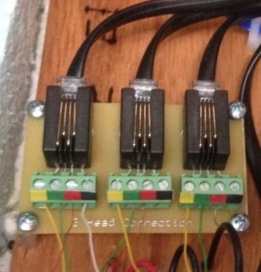
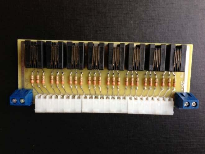
36 Wiring Scheme 5/15/
37 Current MU-ing Existing Newly Added 5/15/

38 Terminal Strip Color Conventions 5/15/
39 Wiring scheme WEST EAST 5/15/
40 Mainline Wiring 5/15/
41 Outer Main Detail 1. PASSIVE End Segment 3. ACTIVE End Segment 2. INTERMEDIATE TRACK 5/15/


42 Simple Oval 5/15/

43 Splicing in Active Modules 5/15/

44 Turnout Wiring 5/15/

45 New Kids on the Block cpnode Arduino based 16 Configurable ports Configurable node address Configurable baud rate Behaves like an SMINI Small: 3 x 2 ½ inches Low cost Built-in Turnout control Expandable 5v DC C/RMInet USB 5/15/
46 Summary Signaling a modular layouts can be done without constraining either the sequence of modules or limiting the function of the signaling system Can run with or without a dispatcher Pre-setup: Create linear list of modules importing the layout plan for that particular setup into CATS Setup = 1) Link the physical modules 2) Load the CATS equivalent 3) Run HUB modular railroad uses: 1. Lenz DCC with a LAN-USB connection 2. C/MRI SMINI boards + (cpnodes & SMicros) 3. C/MRI DCCOD occupancy detectors 4. JMRI & CATS software 5/15/


47 Clearance Form A This is the form that makes a train a train We use it to fill in the needed info for train tracking 5/15/
48 Manual Documentation 5/15/

49 CatNip 5/15/


50 CHUBB to HUB 5/15/
51 Aspect Combinatorics & (NORAC) UPPER HEAD LOWER HEAD Signal RULE (Aspect) GREEN GREEN 281 GREEN YELLOW Not Used GREEN RED 281 YELLOW GREEN 282 YELLOW YELLOW 284 YELLOW RED 285 RED GREEN 283 RED YELLOW 290 RED RED 291
Bruce Chubb s Computer/Model Railroad Interface (C/MRI) 101- The Basics
 101- The Basics") Bruce Chubb s Computer/Model Railroad Interface (C/MRI) 101- The Basics By Jay Beckham http://jaysoscalelayout.blogspot.com/ james@thebeckhams.us Visit the layout Sunday Afternoon 1 My presentation is
Bruce Chubb s Computer/Model Railroad Interface (C/MRI) 101- The Basics By Jay Beckham http://jaysoscalelayout.blogspot.com/ james@thebeckhams.us Visit the layout Sunday Afternoon 1 My presentation is
HUB CATS File Development Documentation
 I. Terminology HUB CATS File Development Documentation Recommended Practices for Computer-Aided Track Signal (CATS) File Development Version 3.0 February 14, 2015 1. Active Module is a module that has
SIGNALING PRACTICES ON PROTOTYPE AND MODEL RAILROADS
 SIGNALING PRACTICES ON PROTOTYPE AND MODEL RAILROADS Bill Ataras September 30, 2013 PROTOTYPE SIGNALING PRACTICE 1. Many different types of signals A. Block signals B. Interlocking signals C. Whistles
Layout Design For Signaling
 Layout Design For Signaling 2 0 1 5, Ro d n e y B l a c k N o v e m b e r 1 5, 2 0 1 5 11/15/2015 1 Download This Presentation 11/15/2015 Layout Design for Signaling 2 Outline 1. Why Signal a Layout 2.
Introduction to Layout Control with JMRI/PanelPro. Create a Detailed CTC Machine Model with JMRI/PanelPro
 Add Signals to your Layout with JMRI/PanelPro Dick Bronson - R R -C irk its, I n c. Other Clinics in this series: Introduction to Layout Control with JMRI/PanelPro 8:30 PM, Sunday, July 13th Create a Detailed
Layout Design For Signaling
 Layout Design For Signaling 2014, Rodney Black h t t p : / / h o m e.c o mca st.n e t / ~ kb 0o ys June 29, 2014 7/5/2014 1 Download 7/5/2014 Layout Design for Signaling 2 Outline 1. Why Signal a Layout
NMRA 2013 Peachtree Express Control Panel Editor - B
 NMRA 2013 Peachtree Express Control Panel Editor - B Dick Bronson RR-CirKits, Inc. JMRI Control Panel Editor for Automatic Train Running Using Warrants Items Portal Table The 'Portal Table' is part of
Simplified Signaling for Modelers
 Simplified Signaling for Modelers Rule 281 Clear 1 Author: Gary Evans North Central Region, Division 3 garytrain47@frontier.com Revision: May 05, 2014 Handout: NORAC Signal Aspects Sheet 2 Introduction
Introduction to Aspect Signaling with JMRI/PanelPro
 Introduction to Aspect Signaling with JMRI/PanelPro Dick Bronson - RR CirKits, Inc. Clinics in this series: Introduction to Aspect Signaling with JMRI/PanelPro 4:00 PM, Wednesday, July 6th Aspect Based
Azatrax Model Railroad Track Signal Control - Single Track
 Installation Guide Azatrax Model Railroad Track Signal Control - Single Track TS2 What it is: The TS2 operates one or two trackside block signals (one in each direction) on one track to simulate the block
Signalist SC1. DCC signal controller user manual Covers configuration for UK signals
 Signalist SC1 DCC signal controller user manual Covers configuration for UK signals 1 Contents Overview... 3 Connections... 3 Ribbon cable connection... 3 DCC track connection... 5 2-aspect signal connections...
Signal Logic Example
 CPL Example Signal Logic Example Block Detect Occupancy Mast Turnout Position Norm/Rev Next From Next Signal Logic Rules Rule to Aspect This Appearance Lamps Effects To previous Signal Drivers With the
Introduction to Aspect Signaling with JMRI/PanelPro
 The Internals of Aspect Signaling with JMRI/PanelPro Dick Bronson - RR CirKits, Inc. Clinics in this series: Introduction to Aspect Signaling with JMRI/PanelPro 4:00 PM, Wednesday, July 6th The Internals
MODULAR RAILROAD SPECIFICATIONS FAQ
 Amherst Belt Lines Modular Railway System Amherst Railway Society Amherst, MA MODULAR RAILROAD SPECIFICATIONS FAQ January 2017 edition January 18, 2017 Amherst Belt Lines Modular Railway System Contents
Visit the Abrams Railroad Empire at
 1 Visit the Abrams Railroad Empire at http://mywebpages.comcast.net/abrams_railroad/ About Dwarf Signals Definitions A ground mounted signal A low home signal (protecting the entrance of a route or block
MSS-CASCADE User Manual
 MSS-CASCADE User Manual Overview The MSS-CASCADE module is designed to provide basic ABS signaling functionality at a block boundary as part of a Modular Signal System implementation ( http://modularsignalsystem.info/
MRC DISPATCHER TRACKSIDE DECODER
 MRC DISPATCHER TRACKSIDE DECODER (Item AD360) Congratulations!! You have just purchased an advanced DCC accessory decoder. Combined with the MRC PRODIGY DCC system or any manufacturer s DCC system, the
Transportation Engineering - II Dr. Rajat Rastogi Department of Civil Engineering Indian Institute of Technology - Roorkee
 Transportation Engineering - II Dr. Rajat Rastogi Department of Civil Engineering Indian Institute of Technology - Roorkee Lecture 25 Interlocking of Track Dear students, welcome you back to the lecture
MRC Prodigy Advance 2. User s Manual
 MRC Prodigy Advance 2 User s Manual T A B L E O F C O N T E N T S 1 Getting Started Introduction... 1-1 DCC Basic Background... 1-1 Specifications and Features... 1-2 System Menu Summary Chart... 1-2 2
GK/GN0658. Guidance on Lineside Signal Aspect and Indication Requirements. Rail Industry Guidance Note for GK/RT0058
 GN This document contains one or more pages which contain colour Published by: Block 2 Angel Square 1 Torrens Street London EC1V 1NY Copyright 2014 Rail Safety and Standards Board Limited GK/GN0658 Issue
Information LG100 Brake Module
 LG100 Braking Module 1 The LG100 is used to send stop commands to NMRA DCC locomotive decoders for the purpose of automatically stopping decoder equipped locomotives. The LG100 is compatible with all NMRA
Push Button Control for a Hidden Reverse Loop and Staging Area
 Push Button Control for a Hidden Reverse Loop and Staging Area With off the shelf components! Presented by Chuck Thomas NMRA Metro-North Division, Northeast Region November 14, 2015 chuckthomas350@gmail.com
Running Signals ANSG 600. Applicability. Publication Requirement. Document Status NSW SMS. External Only October 2015.
 Applicability NSW SMS Publication Requirement External Only Document Status Issue/Revision # Effective from 3.0 11 October 2015 Australian Rail Track Corporation Limited (ARTC) Disclaimer This document
"Sophisticated Model Railroad Electronics"
 LOGIC RAIL TM "Sophisticated Model Railroad Electronics" TECHNOLOGIES 21175 Tomball Pkwy Phone: (281) 251-5813 Suite 287 email: info@logicrailtech.com Houston, TX 77070 http://www.logicrailtech.com Block
Scale Track System. 21 Century y Signal System 2-Rail Manual
 Scale Track System st 21 Century y Signal System 2-Rail Manual TABLE OF CONTENTS Introduction...2-3 Road Signal Board Diagram and Definitions...4-6 Tips for Handling the Circuit Board...6 2-Rail Detector
Be a Digital Professional! Set-Up of TrainController 8.0 Gold for the TurnTable- Decoder TT-DEC-R with Roco H0 Turntable 42615
 LDT Digital-Compendium (TT-DEC-R-TC-001_12_EN) Littfinski DatenTechnik (LDT) Be a Digital Professional! Set-Up of TrainController 8.0 Gold for the TurnTable- Decoder TT-DEC-R with Roco H0 Turntable 42615
Light-It Decoder p/n Lighting decoder w/built-in white LED
 Description of configuration variables (CVs) The factory default value is in parenthesis after the description Decoder Reset CV CV128 Setting this CV to a value of 170 will reset the decoder to factory
British Signalling What the driver sees
 Railway Technical Website Background Paper No. 1 One of a series of papers originally published as pages on RTWP and updated for RTW. Introduction British Signalling What the driver sees by Piers Connor
LE1014W & LE1014MP Ultra-Thin Drive-Select DCC Decoder Art. No Version 4.6 April 2003
 Locomotive decoder LE1014 1 The DIGITAL plus locomotive decoder LE1014 is suitable for all DC motors in HO scale locomotives with continuous current draw of 1.0 Amp. or less. The characteristics of the
With Export all setting information (preferences, user setttings) can be exported into a text file.
 can be exported into a text file.") Release Notes 1 Release Notes What s new in release 1.6 Version 1.6 contains many new functions that make it easier to work with the program and more powerful for users. 1. Preferences Export Menu: Info
Release Notes 1 Release Notes What s new in release 1.6 Version 1.6 contains many new functions that make it easier to work with the program and more powerful for users. 1. Preferences Export Menu: Info
Complete Train Control. Run Your Trains, Not Your Track!
 DN166I1C Features: FX3 Function outputs for prototypical lighting effects and on/off control: Digitrax Program 2 Basic, SuperSonic Direct Decoder Transponder Motor Automatic Decoder Digitrax Complete Train
Lineside Signal Aspect and Indication Requirements
 Lineside Signal Aspect and Indication Requirements Synopsis This document mandates the appearance of lineside signalling system displays and the information they convey. This document contains one or more
Pricelist No. 1/2017 (Validity from 1. February 2017)
") Kleiner Ring 9 D-25492 Heist/Germany Phone: 0049 4122 / 977 381 Fax: Pricelist No. 1/2017 (Validity from 1. February 2017) Order code Description Price per item in incl. German VAT. 4-fold turnout decoder
Kleiner Ring 9 D-25492 Heist/Germany Phone: 0049 4122 / 977 381 Fax: Pricelist No. 1/2017 (Validity from 1. February 2017) Order code Description Price per item in incl. German VAT. 4-fold turnout decoder
To be a Digital-Professional! Digital driving and switching of dual-coil drives with RedBox and 2-rails conductor
 LDT Digital-Compendium (RedBox-DC-001_10_en) To be a Digital-Professional! Digital driving and switching of dual-coil drives with RedBox and 2-rails conductor The main focus of this chapter shall cover
Division Seven Roles
 The NEW extra From the Editor... A er numerous requests we are running the Decoder Pro Clinic again. IT will be held in Berowra same place as the conven on a few years ago. It will take most of Saturday
Lineside Signal Aspects and Indications
 Supersedes Iss 1 (to correct formatting) and supersedes Lineside Signal Aspects and Indications Synopsis This document specifies the appearance of lineside signal aspects and s and the information they
Preventing Fieldbus Physical Layer Problems
 Preventing Fieldbus Physical Layer Problems 1 Introduction Foundation Fieldbus is highly reliable when correctly installed and maintained. The key is in knowing what must be done to start with and to maintain
ECoS - Just Play ESU LLC
 ESU LLC 1 2 ECoS ECoS - Just Play We are proud to present to you our ECoS Digital Central Unit. ECoS is not just another Digital Central Unit on the market: ECoS is the first stepping stone to a comprehensive
Test Division Straight Line Diagram, Block Detection, Transponding, and Simple Signal Logic with JMRI
 http://www.trainweb.org/nrmrc Test Division Straight Line Diagram, Block Detection, Transponding, and Simple Signal Logic with JMRI By: David McDowell, John Wallis and Dave Thompson Version 2/11/2009 http://jmri.sourceforge.net
DR4018 DIGISWITCH HANDLEIDING / MANUAL BEDIENUNGSANLEITUNG / MANUEL. DR4018 DIGISWITCH (v1.2) V1.2 ( )
 V1.2 ( )") DR4018 DIGISWITCH HANDLEIDING / MANUAL BEDIENUNGSANLEITUNG / MANUEL V1.2 (05-02-2012) Copyright 2005 2012 digirails, the Netherlands. All rights reserved. No information, images or any part of this document
DR4018 DIGISWITCH HANDLEIDING / MANUAL BEDIENUNGSANLEITUNG / MANUEL V1.2 (05-02-2012) Copyright 2005 2012 digirails, the Netherlands. All rights reserved. No information, images or any part of this document
Complete Train Control. Run Your Trains, Not Your Track!
 DZ146IN Fits Many N and HO Locomotives.386 x.559 x.137 9.8mm x 14.2mm x 3.48mm Features: FX3 Function outputs for prototypical lighting effects and on/off control: Digitrax Program 2 Basic, SuperSonic
Combo Board.
 Combo Board www.matrixtsl.com EB083 Contents About This Document 2 General Information 3 Board Layout 4 Testing This Product 5 Circuit Diagram 6 Liquid Crystal Display 7 Sensors 9 Circuit Diagram 10 About
Dear Railway Modeller,
 1721_Betra_21_6915_0101.qxd 27.09.2007 12:15 Uhr Seite 25 6915 TURN-CONTROL Turntable Controller Contents Operating instructions GB Page 1. Safety Warnings and Advice on Use 26 1.2. Components, operational
N+1 Redundancy with the VCom HD4040 Upconverter
 N+1 Redundancy with the VCom HD4040 Upconverter Document ID: 47164 Contents Introduction Prerequisites Requirements Components Used Conventions Set Up Communication with the Upconverter VCom Dual4040D
LE062XF DCC Decoder for Atlas N Scale Locomotives
 Locomotive decoder LE062XF 1 The LE062XF DCC decoder is designed to fit specific Atlas N scale locomotives, including the SD50, SD-60, and SD-60M. The characteristics of this decoder are: Provides 0.5
LEVEL CROSSING MODULE FOR LED SIGNALS LCS2
 LEVEL CROSSING MODULE FOR LED SIGNALS LCS2 Fully Flexible Controller for Common-Anode LED signals Automatically detects trains using an infra-red sensor mounted below the track bed Operates attached yellow
A View from the Tower
 A View from the Tower The Fab Lab of The Three Lakes Model Railroad Club along with the Demmer, WI Library hosted a Maker Camp for local area students; Tuesday, August 9 and Wednesday, August 10 2016.
BLINKIN LED DRIVER USER'S MANUAL. REV UM-0 Copyright 2018 REV Robotics, LLC 1
 fg BLINKIN LED DRIVER USER'S MANUAL REV-11-1105-UM-0 Copyright 2018 REV Robotics, LLC 1 TABLE OF CONTENTS 1 OVERVIEW... 3 1.1 CONNECTIONS... 3 1.2 KIT CONTENTS... 3 1.3 ELECTRICAL RATINGS... 3 1.4 SUPPORTED
21-Pin Connector. Dimensions: 1.28 x.69 x.22 or 32.5mm x 17.5mm x 5.6mm
 Our Famous GOOF PROOF NO Questions Asked Warranty TM 21-Pin Connector Scale Functions Function Rating Continuous/Peak HO 8 100 ma 1.3 /2.0 Amp Dimensions: 1.28 x.69 x.22 or 32.5mm x 17.5mm x 5.6mm Main
Lineside Signals, Indicators and Layout of Signals
 To be part superseded by GKRT0045 Iss 4, GKRT0057 Iss 1 and GKRT0058 Iss 1 published on 06/12/2014 Lineside Signals, Indicators and Layout of Signals Synopsis This document defines the format, presentation
DN163K0b. N Scale. Mobile Decoder DCC Plug N Play 1.0 Amp/2.0 Amp Peak 6 FX 3 Functions, 0.5 Amp. Fits Kato N-F3 A&B and Other Locomotives
 Digitrax Command Control Run Your Trains, Not Your Track! DN163K0b Fits Kato N-F3 A&B and Other Locomotives N Scale Mobile Decoder DCC Plug N Play 1.0 Amp/2.0 Amp Peak 6 FX 3 Functions, 0.5 Amp Features:
Turnout Decoder TD Maxi. User Manual - version 0.1.6
 Turnout Decoder TD Maxi - version by Copyright 2013 Tehnologistic SRL All rights reserved No part of this publication may be reproduced or transmitted in any form or by any means, electronic or mechanical,
Chapter 23 Dimmer monitoring
 Chapter 23 Dimmer monitoring ETC consoles may be connected to ETC Sensor dimming systems via the ETCLink communication protocol. In this configuration, the console operates a dimmer monitoring system that
Complete Train Control. Run Your Trains, Not Your Track!
 DN166I0 Features: FX3 Function outputs for prototypical lighting effects and on/off control: Digitrax Complete Train Control Run Your Trains, Not Your Track! Fits InterMountain N-Scale SD40T-2/ SD45T-2
Ground Frames and Shunters Releases
 Ground Frames and Shunters Synopsis This document mandates the interface requirements for ground frames and shunters releases that may be operated by railway undertaking personnel. Copyright in the s is
SIGM20 LED Signal Controller. User Manual
 Sig-naTrak Model railway electronics by GFB Designs SIGM20 LED Signal Controller User Manual Controls up to 8 4 Aspect LED Colour Light Signals with Track Occupancy Detection Logic Sig-naTrak by GFB Designs
GAUGEMASTER PRODIGY EXPRESS
 GAUGEMASTER PRODIGY EXPRESS DCC01 USER MANUAL Version 1.2 2014 1 T A B L E O F C O N T E N T S 1 Getting Started Introduction Specifications and Features Quick Start Connecting to Your Layout Running a
"Sophisticated Model Railroad Electronics"
 LOGIC RAIL TM "Sophisticated Model Railroad Electronics" TECHNOLOGIES 21175 Tomball Pkwy Phone: (281) 251-5813 Suite 287 email: info@logicrailtech.com Houston, TX 77070 http://www.logicrailtech.com Block
RAILWAY INVESTIGATION REPORT R12D0063 UNPROTECTED OVERLAP OF AUTHORITY
 RAILWAY INVESTIGATION REPORT R12D0063 UNPROTECTED OVERLAP OF AUTHORITY AGENCE MÉTROPOLITAINE DE TRANSPORT TRAINS AMT 94 AND AMT 93 MILE 40.8, ADIRONDACK SUBDIVISION ADIRONDACK JUNCTION MONTRÉAL, QUEBEC
17.2 Setting the slow speed Important advice on ABC Push-pull (shuttle) train control Push-pull operation without
 train control Push-pull operation without") 2 Contents 1 Preface...4 2 Important advice, please read first!...5 3 The GOLD series at a glance...6 3.1 Features of the GOLD decoder...6 4 Setting (programming) the decoder...9 4.1 Variable decoder features
2 Contents 1 Preface...4 2 Important advice, please read first!...5 3 The GOLD series at a glance...6 3.1 Features of the GOLD decoder...6 4 Setting (programming) the decoder...9 4.1 Variable decoder features
Block System Interface Requirements
 Block System Interface Requirements Synopsis This document mandates the requirements for block systems interfaces between signalling infrastructure and railway operations. Copyright in the s is owned by
LF101XF Six Function DCC Function Only Decoder Art. No February 2007
 LF101XF function decoder 1 The DIGITAL plus by Lenz LF101XF function decoder is suitable for use in all scales. Features include: Six function outputs rated at 200mA each with advanced function mapping.
Fixed Signals - Rules 1 to 23
 Applicability VIC Publication Requirement External Only Document Status Issue/Revision # Effective from 1 07 August 2011 0 04 October 2015 1 01 July 2018 Australian Rail Track Corporation Limited (ARTC)
2 WIRE - LOOP POWERED TRANSMITTER FOR PT100 AND NI100 PROBES
 EN K20RTD 2 WIRE - LOOP POWERED TRANSMITTER FOR PT00 AND NI00 PROBES General Description The K20RTD instrument converts a temperature signal read by a PT00 (EN 60 75) or NI00 probe with connection by 2,
USER GUIDE. DM Engineering Multi Station Relay Adapter (MSRA and MSRA-RM) Version DM Engineering
 Version DM Engineering") USER GUIDE DM Engineering Multi Station Relay Adapter (MSRA and MSRA-RM) Version 1.35 DM Engineering 2174 Chandler St. Camarillo, CA 91345-4611 805-987-7881 800-249-0487 www.dmengineering.com Overview:
USER GUIDE DM Engineering Multi Station Relay Adapter (MSRA and MSRA-RM) Version 1.35 DM Engineering 2174 Chandler St. Camarillo, CA 91345-4611 805-987-7881 800-249-0487 www.dmengineering.com Overview:
Main Features of this Decoder
 Our Famous GOOF PROOF NO Questions Asked Warranty TM Scale Functions Function Rating Continuous/Peak S/O/G 8 1A 5/10 Amp Dimensions: 3 x 1.41 x.54 or 76.2mm x 36.83mm x 13.716mm Main Features of this Decoder
Headend Systems. Series 9900 RF Signal Manager Modules. Introduction. Description
 Headend Systems Series 9900 RF Signal Manager Modules Introduction Advanced HFC networks now include numerous 2-way interactive services that offer significant new sources of revenue for the system operator.
TRIMBLE GPS / 10MHz REFERENCE MONITOR DISPLAY V January 2015
 TRIMBLE GPS / 10MHz REFERENCE MONITOR DISPLAY V1.2-1.4 January 2015 A display and command module for the Trimble Thunderbolt GPS with 10MHz reference oscillator. by Hubbatech Software Revision Notes: 1.2-2014
100Gb/s Single-lane SERDES Discussion. Phil Sun, Credo Semiconductor IEEE New Ethernet Applications Ad Hoc May 24, 2017
 100Gb/s Single-lane SERDES Discussion Phil Sun, Credo Semiconductor IEEE 802.3 New Ethernet Applications Ad Hoc May 24, 2017 Introduction This contribution tries to share thoughts on 100Gb/s single-lane
HO-Scale Athearn DCC Sound Conversion Kit
 Our Famous WOWKit Compatibility for HO-Scale Bachmann Locomotives Consolidation 2-8-0 WSK-BAC-1 Heavy 4-8-2 WSK-BAC-2 J Class Steam WSK-BAC-3 Alt. for Richmond 4-4-0 WSK-BAC-4 2-8-2 WSK-BAC-5 Richmond
Dimensions: 1.2 x 2.30 x..375 inches 31 x 59 x 9.5 mm Decoder version 3.5 $ This decoder is rated at 4 Amps
 D0SR Amp Decoder Dimensions:. x.30 x..375 inches 3 x 59 x 9.5 mm Decoder version 3.5 $9.95 This decoder is rated at Amps This is an EPF (extended packet format) decoder supporting: Silent Running TM High
Yosemite in HO FROM HALFDOME TO CAMP CURRY
 Yosemite in HO FROM HALFDOME TO CAMP CURRY Don Evans 6x9 layout 07/11/2008 What is it? This document describes a 6-foot by 9-foot HO scale model railroad layout, created in the single car garage walled
Lineside Signals, Indicators and Layout of Signals
 Lineside Signals, Indicators and Layout of Signals Synopsis This document defines the format, presentation and layout of lineside signalling equipment that is used to display movement authority information
VNS2200 Amplifier & Controller Installation Guide
 VNS2200 Amplifier & Controller Installation Guide VNS2200 Amplifier & Controller Installation 1. Determine the installation location for the VNS2200 device. Consider the following when determining the
GAUGEMASTER PRODIGY ADVANCE --- WIRELESS ---
 GAUGEMASTER PRODIGY ADVANCE --- WIRELESS --- DCC04 USER MANUAL Version 1.1 2016 Quick Start diagram 1. Plug the POWER SUPPLY into the BASE UNIT. 2. Plug the AC lead into your wall socket. 3. Using a small
JAMAR TRAX RD Detector Package Power Requirements Installation Setting Up The Unit
 JAMAR TRAX RD The TRAX RD is an automatic traffic recorder designed and built by JAMAR Technologies, Inc. Since the unit is a Raw Data unit, it records a time stamp of every sensor hit that occurs during
POINTS POSITION INDICATOR PPI4
 POINTS POSITION INDICATOR PPI4 Monitors the brief positive operating voltage across points motors when they are switched Lights a corresponding led on a control panel to show the last operation of each
Network Safeworking Rules and Procedures
 Network Safeworking Rules and Procedures Fixed Signals Rule Number: 6005 Version 1.0, 31 March 2016 Fixed Signals Rule Number: 6005 Document Control Identification Document title Number Version Date 6005
APM CALIBRATION PROCEDURE Rev. A June 3, 2015
 APM CALIBRATION PROCEDURE Rev. A June 3, 2015 Calibration of the APM allows system parameters such as coupler coupling values, interconnecting cable losses and system feeder losses to be programmed into
N14IP Decoder. $29.95 Decoder version 3.5. Direct plug in for Con Cor N-Scale PA1, and other locomotives with DCC 8 pin socket
 N4IP Decoder $29.95 Decoder version 3.5 Direct plug in for Con Cor N-Scale PA, 4-8-4 and other locomotives with DCC 8 pin socket This is an EPF (extended packet format) decoder supporting: Silent Running
V pro8 QUICK START GUIDE
 QUICK START GUIDE Welcome to your V pro8 FIRST STEPS POWERING ON CONNECTING YOUR COMPUTER Thank you for buying the Lawo V pro8, a true high-quality product developed and manufactured in Rastatt, Germany.
Kramer Electronics, Ltd. USER MANUAL. Model: VS x 1 Sequential Video Audio Switcher
 Kramer Electronics, Ltd. USER MANUAL Model: VS-120 20 x 1 Sequential Video Audio Switcher Contents Contents 1 Introduction 1 2 Getting Started 1 2.1 Quick Start 2 3 Overview 3 4 Installing the VS-120 in
Responding to Signals and Signs
 Applicability NSW SMS Publication Requirement External Only Document Status Issue/Revision # Effective from 4.0 11 October 2015 Australian Rail Track Corporation Limited (ARTC) Disclaimer This document
DLP600M 6+1 Relay Module for Heating and Cooling Plants
 Product Sheet TH6.25 Thermostat Type DLP600M DLP600M 6+1 Relay Module for Heating and Cooling Plants The DLP 600 M is a relay module for activation of loads (namely thermal actuators or circulators) in
Complete Train Control. Run Your Trains, Not Your Track!
 DH166PS Fits Many DCC-Ready HO Locomotives.672 x 1.074 x.259 17.08mm x 27.28mm x 6.6mm Features: FX3 Function outputs for prototypical lighting effects and on/off control: Digitrax Complete Train Control
ENGR 1000, Introduction to Engineering Design
 ENGR 1000, Introduction to Engineering Design Unit 2: Data Acquisition and Control Technology Lesson 2.4: Programming Digital Ports Hardware: 12 VDC power supply Several lengths of wire NI-USB 6008 Device
Decoder version 3.5. Plug and play decoder for N-Scale Atlas Classic Series GP7, GP9, GP30, GP35
 NA Function Decoder $9.95 Decoder version 3.5 Plug and play decoder for N-Scale Atlas Classic Series GP7, GP9, GP30, GP35 This is an EPF (extended packet format) decoder supporting : Silent Running TM
Manual for the NMRA compatible DCCaccessory
 Manual for the NMRA compatible DCCaccessory decoder Assembled WDECN-TN Parts Kit WDECN-TN-B 1.1 Properties 2006 Gerard Clemens This model railroad accessory decoder is based on the ATMEL ATTiny2313 microcontroller.
ORANGE COUNTY MODULE RAILROADERS, INC. MODULE STANDARDS
 ORANGE COUNTY MODULE RAILROADERS, INC. MODULE STANDARDS The purpose of these Module Standards is to establish a minimum set of specifications that will enable a club member to construct a module that is
Gigabit Multi-mode SX to Single Mode LX Converter. User s Manual NGF-728 Series. Warning COPYRIGHT
 COPYRIGHT Gigabit Multi-mode SX to Single Mode LX Converter User s Manual NGF-728 Series All rights reserved. No part of this publication may be reproduced, stored in a retrieval system, or transmitted
To be a Digital-Professional! American Color Light signals digital controlled by the Light-Signal Decoder LS-DEC-USA
 To be a DigitalProfessional! American Color Light sials digital controlled by the LightSial Decoder LSDECUSA Detailed constructed light sials with a realistic digital control are a real eyecatcher not
FS3. Quick Start Guide. Overview. FS3 Control
 FS3 Quick Start Guide Overview The new FS3 combines AJA's industry-proven frame synchronization with high-quality 4K up-conversion technology to seamlessly integrate SD and HD signals into 4K workflows.
Video Extender DS128 DSRXL. Instruction Manual. 8-Port Cat5 VGA Digital Signage Broadcaster with RS232 and Audio
 DS128 DSRXL Instruction Manual Video Extender 8-Port Cat5 VGA Digital Signage Broadcaster with RS232 and Audio Cat5 VGA Digital Signage Receiver with RS232 and Audio FCC Compliance Statement This equipment
Aurora Grid-Tie Installation Instructions (Model Number: PVI-3.0-OUTD-US-W) Revision 4.1
 Revision 4.1") Aurora Grid-Tie Installation Instructions (Model Number: PVI-3.0-OUTD-US-W) Revision 4.1 Contents 1) Grid-Tie Installation Block Diagram... 3 2) Installation Steps.... 4 2.1) Initial Setup.... 4 2.1.1)
Aurora Grid-Tie Installation Instructions (Model Number: PVI-3.0-OUTD-US-W) Revision 4.1 Contents 1) Grid-Tie Installation Block Diagram... 3 2) Installation Steps.... 4 2.1) Initial Setup.... 4 2.1.1)
EEG A1452 SCTE-104 Inserter Frame Card
 EEG A1452 SCTE-104 Inserter Frame Card Product Manual EEG Enterprises, Inc. 586 Main Street Farmingdale, New York 11735 TEL: (516) 293-7472 FAX: (516) 293-7417 Copyright EEG Enterprises, Inc. 2017 All
Micro-DCI 53ML5100 Manual Loader
 Micro-DCI 53ML5100 Manual Loader Two process variable inputs Two manually controlled current outputs Multiple Display Formats: Dual Channel Manual Loader, Single Channel Manual Loader, Manual Loader with
(Skip to step 11 if you are already familiar with connecting to the Tribot)
") LEGO MINDSTORMS NXT Lab 5 Remember back in Lab 2 when the Tribot was commanded to drive in a specific pattern that had the shape of a bow tie? Specific commands were passed to the motors to command how
LEGO MINDSTORMS NXT Lab 5 Remember back in Lab 2 when the Tribot was commanded to drive in a specific pattern that had the shape of a bow tie? Specific commands were passed to the motors to command how
Guidance on Lineside Signals, Indicators and Layout of Signals. Rail Industry Guidance Note for GK/RT0045
 GN Published by Block 2 Angel Square 1 Torrens Street London EC1V 1NY Copyright 2012 Rail Safety and Standards Board Limited GK/GN0645 Issue Two: March 2012 Rail Industry Guidance Note for GK/RT0045 Issue
Noise Detector ND-1 Operating Manual
 Noise Detector ND-1 Operating Manual SPECTRADYNAMICS, INC 1849 Cherry St. Unit 2 Louisville, CO 80027 Phone: (303) 665-1852 Fax: (303) 604-6088 Table of Contents ND-1 Description...... 3 Safety and Preparation
The Haply Development Kit
 The Haply Development Kit Introduction The Haply development kit is a robust and adaptable open-source hardware development platform for haptic applications. Designed to be accessible to novices and experts